enhancing the structural behavior of wide beams through
TRANSCRIPT
The Egyptian International Journal of
Engineering Sciences and Technology
Vol. 31 (2020) 10–18
https://eijest.journals.ekb.eg/
________ * Corresponding author. Tel. +0201098907072.
E-mail address: [email protected]
Enhancing the Structural Behavior of Wide Beams Through Reinforcement
Schemes
Mohamed Husaina, Mahmoud A. Khater
b, Basma E. Helal
c*
aProf of Concrete Structures, Faculty of Engineering, Zagazig University, Zagazig, Egypt bLecturer Structural Engineering Department, Faculty of Engineering, Zagazig University, Zagazig, Egypt
cB.sc Structural Engineering, Faculty of Engineering, Zagazig University, Zagazig, Egypt
A R T I C L E I N F O A B S T R A C T
Keywords: Reinforced Concrete
Beam-Column Connection Computational Simulations
In this paper, numerical analysis of wide beams was presented. The proposed models were
loaded with a static seismic load. Diverse models of reinforced concrete wide beams were
studied numerically by ANSYS platform, and a parametric study was conducted. The studied
parameters were web reinforcement percentage, tensile reinforcement percentage, and
compressive reinforcement percentage. The values of tensile reinforcement percentage were
(1.5%, 1%, 0.7%, 0.3%) of cross-section area, compressive reinforcement percentage were
(0.8,0.6,0.5,0.4) of the tensile reinforcement ratio and web reinforcement percentage were
(0.13%, 0.067%). The influence of these parameters was studied on ductility, dissipation,
toughness, stiffness and over strength. The results demonstrated that the studied parameters
affected all these properties, and the smallest ductility was noticed in the wide beam (B7)
which has a value of 1.1.
1. Introduction
The width of R.C wide beams is bigger than that of the
supporting columns, its structural behavior (shear and flexure)
normally varies than that of the dropped beams. Stirrups
configuration in R.C wide beams may influence its
contribution to shear resistance as a ratio of the nominal shear
stirrup strength. The deflection of the R.C wide beams is
more than that of the dropped beams due to the variation of
their inertia. Reinforced concrete structures with wide shallow
beams supply various advantages and needs from
construction and architectural points of view. A wide shallow
beams system may decrease the amount of formwork through
repetition and then the construction cost can be greatly
decreased and the construction works can be simplified.
ACI-ASCE committee 352 [1] recommended that wide
beam column connections not to be used when designing to
afford seismic forces. The committee has suggested that such
connections should be estimated experimentally so that the
code provisions can be advanced for their use in seismic
zones. Unlike to the committee 352 recommendations, the
ACI Building code does allow the use of wide beam-column
connections in seismic zones ACI Committee 318 [2]. On this
code the width of wide beam should not exceed the column
breadth plus 1.5 times the depth of the wide beam.
Some researchers examined Wide Beam-Column
Connections Under Earthquake Form Loading, Gentry,T.R.
and Wight,J.K [3] studied four specimens experimentally
(exterior wide beam-column connections) and the influence
the following parameter on this specimens, beam width to
column width ratio / (2.43, 2.14, 2.43, 2.43), fraction of
the longitudinal reinforcement anchored in the column core,
the column moment to beam moment ratio Mr (1.46, 1.64,
1.5, 1.17) , =4000 psi, all steel =60 for all specimens and
stirrups =48ksi and hook distance was increased beyond the
ACI requirements of 6 . Four specimens were tested in
fixture with pin connections and the column exposed to a 20-
kip axial compressive load to avoid tension in the column
through testing. It was subjected to increasing cyclic
displacements of 0.5% to 5% equivalent story drift. The
behavior noted in the test specimens specified that exterior
wide beam-column connections will be better if the transverse
beam was not to a big extent cracked in torsion.
Recently, some researchers directed their efforts to study
shear behavior of wide shallow beam. Ibrahim et el [4]
10

Mohamed Husain, et.al / Enhancing The Strucuture Behavior Of Wide Beams Through Reinforcement Schemes
studied four specimens experimentally. The dimensions of the
specimens were width= 560 mm, depth= 215 mm, length=
1800 mm and shear span depth ratio a/d =4.52 these were
reinforced with congruent longitudinal steel with ten bars of
diameter= 16 mm. Specimen B4 reinforced with stirrups but
other specimens no reinforced with stirrups. Specimen B1
includes a vertical solid steel plates on longitudinal, B2
includes a vertical steel plates with hollow on longitudinal
and B3 includes a vertical steel plates with hollow on width
of the beam. Steel plates with thickness = 4 mm, = 45
N/ . Deformed steel bars were used in this work with
diameters of (16mm) for longitudinal reinforcement in
tension side with 100mm length hanging at both ends using
90° standard hook. While deformed steel bars (12mm) were
used as web reinforcement in specimen B4. All specimens
were tested using a hydraulic universal testing machine of
(2000kN capacity) under monotonic loads up to ultimate load.
Cracking behavior for all specimens, specimens were free of
cracks in the early stages of loading. All specimens failed in
shear and shear cracks traversed the compression region of
specimen section. For specimens B1, B2 and B4, the shear
cracks began without the occurrence of flexural cracks. For
specimen B3, it was observed that the first early cracks were
vertical flexural cracks and increasing the applied load, a
series of flexural cracks were shaped at the bottom in the
shear span zone and gradually spread toward the loading
point while no crack had been observed at beam ends. The
crushing of concrete in the strut region was caused by
reaching the compressive stress in concrete to its ultimate
value before yielding or rupturing these gagger plates were
clear.
The objective of the study is to investigate the effect of
different reinforcement configurations (web reinforcement,
long reinforcement, compression reinforcement) on the
reinforcement concrete wide beam structural behavior.
2. Verification
2.1 Specimens dimensions and material properties
A shallow beam from literature Tested by (Shuraim,
was studied used numerical analysis via ANSYS software.
Dimension of the tested beams were 700 mm, 3000 mm, 180
mm width, span, depth, respectively. The column cross
section had dimensions B =140 mm, t =200 mm. Reinforced
steel for beam (Compressive steel = 7ϕ14, Tensile steel =
7ϕ16, Horizontal transverse steel = 6ϕ12 @ 150mm,Stirrups
of the beam = 9ϕ16/m) . The reinforcement steel for the
column was (Longitudinal rebars = 8ϕ16, stirrup 1ϕ8 for four
leg configurations as shown Fig (1). The material properties
were, = 580 MPa for longitudinal and horizontal transverse
rebars of the beam, = 465 MPa for stirrups of the beam.
The concrete compressive strength was applied the load over
the full-width of plates situated at the middle of each span.
Each specimen was loaded with several load increments up to
failure using displacement control scheme, as shown Fig (2).
The wide beam of (Shuraim, ) were modeled by
using ANSYS platform as shown Fig (3) and compared
results with experimental results.
Fig (1) Details of tested beams (Shuraim, .
Fig (2) Test setup used by (Shuraim, .
11
EIJEST Vol. 31 (2020) 10–18
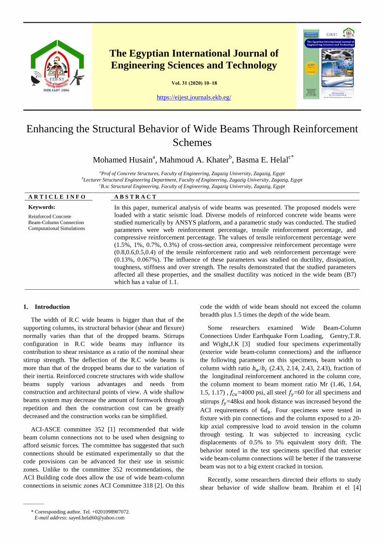
Fig (3) Finite element model details of studied beams
2.2 comparison between experimental and numerical
program results
The results of proposed model were compared to
experimental results carried out by (Shuraim, .The
comparison showed good agreement between the results. The
comparison depended mainly on the ultimate load and failure
pattern of the studied specimen. The finite element model
showed a failure load of 830 kN which is about 92% of the
experimental result recorded by (Shuraim, ,which
was about 893 kN. The failure was noticed in both specimens
near to the intermediate support as shown in Fig (4), at which
the concrete reached its maximum stress value. The
longitudinal steel reinforcement bars reached their yield stress
value at the same position as shown in Fig (5). The deflection
value was compared with that calculated manually and
showed good agreement as well, as shown in Fig (6). The
cracks shown in the proposed model agreement as well with
the tested specimens, as shown in Fig (7) and (8).
Fig (4) Stress in concrete
Fig (5) Stress in steel reinforcement
Fig (6) deflection of studied beam
Solid 65
Solid 185
Bottom rebars
Top rebars
Horizontal transverse rebars
Link 180
12
Mohamed Husain, et.al / Enhancing The Strucuture Behavior Of Wide Beams Through Reinforcement Schemes
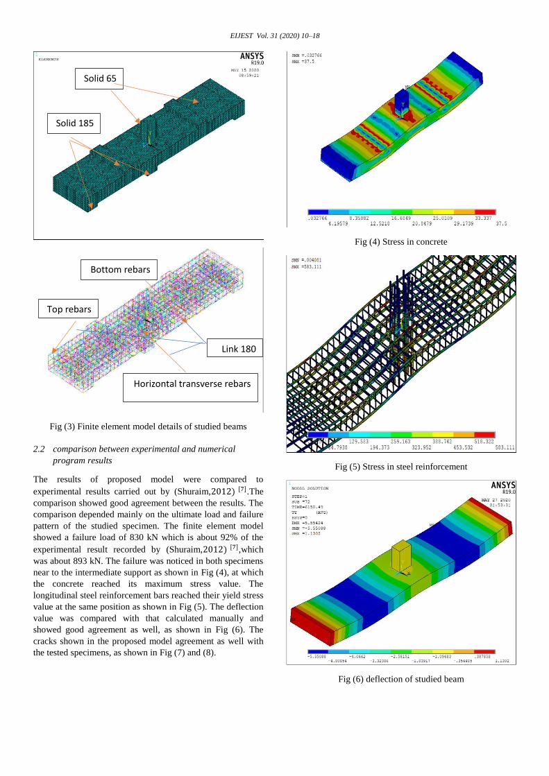
Fig (7) Crack pattern in finite element model
Fig (8) Cracks pattern for experimental from [7].
3. Numerical analysis (ANSYS)
3.1 Model Discretization
An eight-node solid element, Solid65, was used to model
the concrete. The solid element has eight nodes with three
degrees of freedom at each node – translations in the nodal x,
y, and z directions. The element is able to plastic deformation,
cracking in three perpendicular directions, and crushing. The
beam and column are modeled using 3D solid 65 as illustrated
Fig (9), A Link180 element was used to model the steel
reinforcement. Two points are required for this element. Each
point has three degrees of freedom, – translations in the nodal
x, y, and z directions. Compressive, tensile steel, longitudinal
steel column and stirrups was modeled using link 180 as
shown Fig (10). In ANSYS the load can be applied in steps.
Each load step is separated to load increments. The size of the
load increments was chosen to achieve convergence and at
the same time attains an adequate level of accuracy, the
maximum chosen mesh dimension was 150 X 150 mm.
3.2 Details of models
The proposed specimens were large scale and represent
columns connected to a wide beam at the middle. The
dimension of proposed model were 1500mm, 300mm, 6000mm
width, depth, span respectively and column cross sections =
500*500 mm, column height=1500mm, as illustrated
Fig(11), =360 N/ for Tensile, compressive steel,
column longitudinal and stirrups, =280 N/ for Stirrups
of beam , =30 N/ for beams and =45N/ for
column, s modulus of concrete was taken 2.9 X
MPa from the slope of the stress-strain curve Fig (12), the
Poison's ratio was assumed 0.2. The variations in the studied
models (B1 to B8) was in tensile reinforcement ratio (1.5%,
1%, 0.7%, 0.3%) of cross section area, compressive
reinforcement percentage (0.8, 0.6, 0.5, 0.4) of tensile
reinforcement ratio and web reinforcement ratio (0.13%,
0.067%) as illustrate in table 1. Diameter of longitudinal bars
for column were 25 . The boundary conditions of the
finite element models were shown in Fig (13). The supports
were restrained in all directions (Z, X and Y). Horizontal force
was applied at top of the column. The proposed models were
loaded with a static seismic load The loading steps in the sub-
steps should be very small to avoid converging problem.
Fig (10) Modelling reinforcement steel
Fig (9) Modelling concrete
Cracks
13

EIJEST Vol. 31 (2020) 10–18
Fig (12) Stress-Strain Curve for Concrete
Fig (13) Applied loads and Boundary conditions.
Table 1: Reinforcement details of studied models
Beams
web
reinforcement
ratio
Tensile
reinforcement ratio
(As)
Compressive
reinforcement
ratio
B1 0.067 1.5% Ac 0.8As
B2 0.13 1.5% Ac 0.8As
B3 0.067 1.0% Ac 0.6As
B4 0.13 1.0% Ac 0.6As
B5 0.067 0.7% Ac 0.5As
B6 0.13 0.7% Ac 0.5As
B7 0.067 0.3% Ac 0.4As
B8 0.13 0.3% Ac 0.4As
4. Results
4.1 Force-Displacement Curve
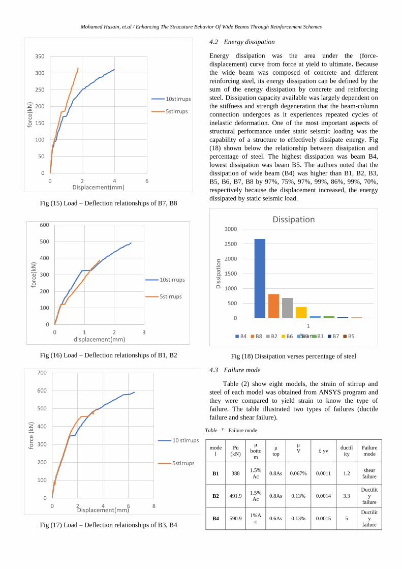
The curves shown below illustrate the relationship
between the force in y-direction and displacement in x-
direction for eight wide shallow beams (B1, B2, B3, B4, B5,
B6, B7, B8). Fig (14) shows a comparison between the load-
deflection curves expected numerically for wide beam (B5)
and wide beam(B6). The authors noted that wide beam (B5)
collapsed at ultimate load 300kN before wide beam (B6) at
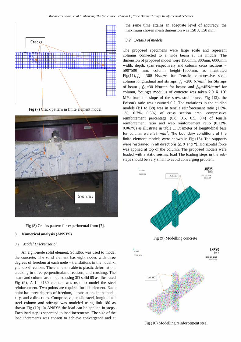
ultimate load 400kN. The authors noted that wide beam (B7)
collapsed at ultimate load 330kN before wide beam (B8) at
ultimate load 340kN as shown Fig (15), wide beam (B1) at
ultimate load 400 kN failed before wide beam(B2) at ultimate
load 500 kN as shown Fig (16), wide beam (B3) at ultimate
load 500 kN failed before wide beam(B4) at ultimate load 600
kN, displacement=1.1, 2.7, 1.8, 4, 1.5, 3, 3.5, 6.5 mm for B5,
B6, B7, B8, B1, B2, B3, B4 respectively. The beams
reinforced by five stirrups per meter collapsed before the
beams reinforced by ten stirrups per meter, this may be due to
the small number of stirrups per meter.
Fig (14) Load – Deflection relationships of B5, B6
0
5
10
15
20
25
30
35
0 0.001 0.002 0.003 0.004
Stress-StrainCurve
0
50
100
150
200
250
300
350
400
0 1 2 3
forc
e (k
N)
Displacement(mm)
10stirrups
5stirrups
Fig (11) Beam and column Dimension
Applied Load
Boundary Conditions
14
Mohamed Husain, et.al / Enhancing The Strucuture Behavior Of Wide Beams Through Reinforcement Schemes
Fig (15) Load – Deflection relationships of B7, B8
Fig (16) Load – Deflection relationships of B1, B2
Fig (17) Load – Deflection relationships of B3, B4
4.2 Energy dissipation
Energy dissipation was the area under the (force-
displacement) curve from force at yield to ultimate. Because
the wide beam was composed of concrete and different
reinforcing steel, its energy dissipation can be defined by the
sum of the energy dissipation by concrete and reinforcing
steel. Dissipation capacity available was largely dependent on
the stiffness and strength degeneration that the beam-column
connection undergoes as it experiences repeated cycles of
inelastic deformation. One of the most important aspects of
structural performance under static seismic loading was the
capability of a structure to effectively dissipate energy. Fig
(18) shown below the relationship between dissipation and
percentage of steel. The highest dissipation was beam B4,
lowest dissipation was beam B5. The authors noted that the
dissipation of wide beam (B4) was higher than B1, B2, B3,
B5, B6, B7, B8 by 97%, 75%, 97%, 99%, 86%, 99%, 70%,
respectively because the displacement increased, the energy
dissipated by static seismic load.
Fig (18) Dissipation verses percentage of steel
4.3 Failure mode
Table (2) show eight models, the strain of stirrup and
steel of each model was obtained from ANSYS program and
they were compared to yield strain to know the type of
failure. The table illustrated two types of failures (ductile
failure and shear failure).
Table :2 Failure mode
mode
l
Pu
(kN)
µ
bottom
µ
top
µ
V
£ yv ductil
ity
Failure
mode
B1 388 1.5%
Ac 0.8As 0.067% 0.0011 1.2
shear
failure
B2 491.9 1.5%
Ac 0.8As 0.13% 0.0014 3.3
Ductilit
y failure
B4 590.9 1%A
c 0.6As 0.13% 0.0015 5
Ductility
failure
0
50
100
150
200
250
300
350
0 2 4 6
forc
e(kN
)
Displacement(mm)
10stirrups
5stirrups
0
100
200
300
400
500
600
0 1 2 3
forc
e(kN
)
displacement(mm)
10stirrups
5stirrups
0
100
200
300
400
500
600
700
0 2 4 6 8
forc
e (k
N)
Displacement(mm)
10 stirrups
5stirrups
0
500
1000
1500
2000
2500
3000
1
Dis
sip
atio
n
Beams
Dissipation
B4 B8 B2 B6 B3 B1 B7 B5
15

EIJEST Vol. 31 (2020) 10–18
B6 380.7 0.7%
Ac 0.5As 0.13% 0.0014 1.6
Ductility
failure
B8 311.3 0.3%
Ac 0.4As 0.13% 0.0015 2.6
Ductility
failure
B3 496.4 1%A
c 0.6As 0.067% 0.0013 1.1
shear
failure
B5 286.4 0.7%
Ac 0.5As 0.067% 0.0007 1.1
shear
failure
B7 315.7 0.3%Ac
0.4As 0.067% 0.0001 1.1 shear
failure
Where:
Ac=B*T B=1500 mm T=300 mm
As=µbottom *Ac, µbottom is the ratio of the reinforcement in the
concrete section
µv = (n*A) \ (B*S), µv is percentage of stirrups per meter
n=no of branches
S= Distance between stirrups
A= area of bar
B=width of beam
4.4 Over strength factor(Ω)
Overstrength was ratio between yield-ultimate tangent
stiffness to Initial stiffness. The authors noted that the highest
over strength was wide beam with reinforcement 1% Ac in
tensile and 0.6As in compression, ten stirrups per meter with
value 5.6. The outhers noted that the beam B4 was higher
than the B1, B2, B3, B5, B6, B7, B8 by 84% ,39%, 41%,
96%, 45%, 93%, 38% respectively. Fig (19) shown below the
relationship between over strength and percentage of steel.
Fig (19) over strength
4.5 Stiffness
It was ability of the body to resist the deformation by an
applied force. It was the ratio of yield force to the yield
displacement. Fig (20) demonstrates the relationship between
initial stiffness and percentage of steel for various specimens.
The highest stiffness was beam B2, lowest stiffness was beam
B3. The authors noted that the beam B2 was higher than the
B1, B3, B4, B5, B6, B7, B8 by 27%, 58%, 25%, 40%, 43%,
52%, 52% respectively.
Fig (20) Stiffness
4.6 Crack and crushing
Fig (21, 22, 23,24) shown below cracks and crushing at
ultimate load of various specimens. Cracks that happened
in the following specimens were shear cracks which may
be due to that the bent bars and stirrups were inadequate
to withstand the shear force or the impact of loading on it
was more than the load can be sustained by the flexure
cracks were due to over Load or the reinforcement was
not enough to resist the stress. Inclined cracks and
vertical cracks represented shear cracks.
0
1
2
3
4
5
6
Ove
r St
ren
gth
Beams
Over strength
B2
B1
B4
B3
B6
B5
B8
B7
0
50
100
150
200
250
300
350
400
Stif
fnes
s (K
N/m
m)
Beams
Initial stiffness(kN)
B2 B1 B6 B5 B4 B3 B8 B7
16

Mohamed Husain, et.al / Enhancing The Strucuture Behavior Of Wide Beams Through Reinforcement Schemes
Fig (21) Cracks at Pu=400 kN for beam B1
Fig (22) Cracks at Pu=500 kN for beam B2
Fig (23) Cracks at Pu=500 kN for beam B3
Fig (24) Cracks at Pu=600 kN for beam B4
5. Conclusion
1. The biggest dissipation occurred at beam (B4) with
reinforcement (1.0% Ac, 0.6As, 10 stirrups per meter)
and the smallest dissipation occurred at beam (B5) with
reinforcement (0.7% Ac, 0.5As, 5 stirrups per meter).
2. Stiffness for beam B2 with reinforcement (1.5% Ac,
0.8As, 10 stirrups per meter) was the highest and the
beam B3 with reinforcement (1.0% Ac, 0.6As, 5 stirrups
per meter) was the lowest.
3. Overstrength for beam B2 with reinforcement (1.5% Ac,
0.8As, 10 stirrups per meter) is bigger than that the beam
B1 with reinforcement (1.5% Ac, 0.8As, 5 stirrups per
meter) which is about 74%.
4. The maximum deflection for wide beam B5 with
reinforcement (0.7% Ac, 0.5As, 5 stirrups per meter) and
wide beam B6 with reinforcement (0.7% Ac, 0.5As, 10
stirrups per meter) were 1.1 mm and 2.7 mm
respectively. 5. The beam B4 with reinforcement (1.0% Ac, 0.6As, 10
stirrups per meter) is the best for ductility, toughness,
Shear.
Reference:
[1] ACI-ASCE Committee 352"Recommendations for Design of Beam-
Column Joints in Monolithic Reinforced concrete structures, "ACI Journal, Vol. 82. No 3, May-JUNE 1985, pp. 266-283.
www.doi.org/10.14359/10333
17

EIJEST Vol. 31 (2020) 10–18
[2] ACI Committee 318 “building code requirements for reinforced concrete” (ACI 318-89), American concrete institute, Detroit, Michigan,
1989.
[3] T. R. Gentry, and J. K. Wight, "Reinforced Concrete Wide Beam-
Column Connections Under Earthquake-Type Loading, "Report No.
UMCEE 92-12, Department of Civil and Environmental Engineering,
University of Michigan, Ann Arbor, Michigan, 1992. [4] A. M. Ibrahim and W. D. Salman,“Effect of Steel Plates on Shear
Strength of Wide Reinforced Concrete Beams” on College of Eng.,
Diyala University (2015). [5] S.H. LUK and J.S. KUANG, “Seismic Behavior of RC Exterior Wide
Beam-Column Joints”, The Hong Kong University of Science and
Technology, Hong Kong, 2012. [6] T. Elrakeeb, E. I. Ismail, A. I. Arfa and K. Z. Soliman ,“Validation of
FE Modeling for Shallow Reinforced Concrete Beams”, Housing and
Building National Research Center, Cairo, Egypt, July 2018. [7] A. B. Shuraim and A.M. ASCE1 ,“Transverse Stirrup Configurations in
RC Wide Shallow Beams Supported on Narrow Columns”, 2012.
https://doi.org/10.1061/(ASCE)ST.1943-541X.0000408
[8] E. C. Bentz (2005), “Empirical modeling of reinforced concrete shear strength size effect for members without stirrups.” ACI Struct. J.,
102(2), 232–241. https://doi.org/ 10.14359/14274
[9] A. Benavent-Climent, “Seismic behavior of RC wide beam-column
connections under dynamic loading”. J Earthquake Eng. 2007; 11:493–
511. https://doi.org/10.1080/13632460601064814
[10] H. Behnam, J.S. Kaung and R.Y.C. Huang, “Exterior wide beam-column connections: effect of beam width ratio on seismic behaviour”.
https://doi.org/10.1016/j.engstruct.2017.05.044
[11] M.J. Davey, K. Abdouka and R. Al-Mahaidi, “Exterior post-tensioned band beam to column connections under earthquake loading”. Aust J
Struct Eng 2016;17 (1):14–27.
https://doi.org/10.1080/13287982.2015.1116179 [12] D. Angelakos, E.C. Bentz. and M. P. Collins, ”Effect of Concrete
Strength and Minimum Stirrups on Shear Strength of Large Members”.
ACI Structural Journal, V. 98, No. 3, May-June 2001, pp. 291-300. https://doi.org/10.14359/10220
18