behavior of high strength reinforced concrete wide beams
TRANSCRIPT

Civil and Environmental Research www.iiste.org
ISSN 2224-5790 (Paper) ISSN 2225-0514 (Online)
Vol.12, No.12, 2020
32
Behavior of High Strength Reinforced Concrete Wide Beams Under Bending and Torsion Effects
Dr. Wisam Hulail Sultan
Lecturer, Civil Engineering Department, Al-Mustansiriyah University, Baghdad, Iraq
Abstract The research includes experimental study for behavior of HSC wide beams under bending and torsion moments. Nine beams of 1200×220×110 mm were tested. Parameters of the study were torque to bending moments ratio (T / M), longitudinal and transverse reinforcement ratios (ρL & ρ t). The results indicated that presence of torsion combined with bending moment significantly reduces the ultimate moment capacity (Mu) and results in changing beam failure from flexural mode to torsional or flexural-torsional mode. Also torsion effect results in reducing cracking moment capacity and propagation of inclined cracks combined to vertical cracks. These influences for torsion increase with increasing T / M ratio and ρL and with decreasing ρt. Increasing ρL results in significant increase in Mu especially when T / M decreases, while increasing ρt results in slight increase in Mu and its effect decay as T / M decreases. Increasing T / M ratio makes Moment-deflection response softer especially in case of high ρL. Increasing ρL makes this response stiffer especially in case of pure bending whereas increasing ρt slightly stiffens this response in advanced loading stages for high values of T / M. Torque-rotation response is stiffer as T / M ratio increases. Also, increasing ρL makes the responses stiffer for all values of T / M while increasing ρt makes it slightly stiffer in advanced loading stages. Mathematical expression for calculation of ultimate moment capacity for this type of beams was proposed and give results that have good agreement with experimental results. Keywords: wide beam, high strength concrete, bending, torsion, deflection, rotation. DOI: 10.7176/CER/12-12-05 Publication date: December 31st 2020 1. Introduction Wide beams (thick slabs) are characterized by their large width which approximately equivalent to twice of their total depth or more (Haido & Musa 2013). The use of wide-shallow beams is becoming popular in one-way reinforced concrete joist floors for constructional and architectural advantages (Shuraim & Al-negheimish 2011). They are frequently used as economical transfer elements where the total structural depth must be kept to a minimum. The wide beams may be used to carry direct forces, or to serve as primary transfer elements (Said & Elrakib 2013). The use of reinforced concrete wide beams is advantageous for many reasons. In buildings such as warehouses, commercial buildings, parking garages, and office buildings, reinforced concrete wide beams with a width-depth ratio of at least 2 are used to reduce floor height and facilitate the run of services under the floor (Mohammadyan –Yasouj et al. 2015). When thick slabs are used, the time savings in construction due to the simplicity of formwork, reinforcement placement, and access by following trades can significantly enhance the cost effectiveness of the overall project (Sherwood et al. 2006). Also, wide beams are useful to reduce congestion of the reinforcement in column strip of flat slab system and for more controlling on deflection and cracking requirements in addition to their role in provision appropriate punching shear strength for this system without using drop panel nor increasing slab thickness. 2. Research Significant Most researches that concern to this topic were concentrated on shear capacity of wide beams through determination the effective width used in calculation of their shear strength and role of web reinforcement in their shear strength because the failure of this type of beams is mostly governed by shear (Said & Elrakib 2013 , Mohammadyan –Yasouj et al. 2015 , Sherwood et al. 2006 , Lotfy et al. 2014 & Lantsoght et al. 2014). Therefore, this work tries the investigation on another behavior for this type of beams through study their behavior when they subjected to combined effect of torsion and bending. The work involves studying case of application of pure bending moment loading and case of application of loading combined from torsion and bending moments with different values of torque to bending moments ratios (T / M). In ordinary beams, the bending moments are applied about strong axis of the beam, while in wide beams the bending moments are applied about weak axis. This may make the behavior of wide beams subjected to both bending and torsional moments differs from the behavior of ordinary beams subjected to the same type of loading.
Irrespectively shear effect, interior concrete beams are generally subjected to pure bending or small ratio of torque to bending moments due to inequality of slabs spans on two sides of the beam or due to non-corresponding of the loading on the beam sides. While the edge beams are ordinary subjected to both effects of bending and torsion with different ratios between their moments. Thus, the study adopt different values of (T / M).
It is useful using high strength concrete in casting this type of beams to control on serviceability requirements

Civil and Environmental Research www.iiste.org
ISSN 2224-5790 (Paper) ISSN 2225-0514 (Online)
Vol.12, No.12, 2020
33
(deflection and cracking), and increasing shear strength of them to avoid the shear failure without using web reinforcement. Therefore, this type of concrete was adopted in this study for all wide beams. Also, the study takes into account the variation in longitudinal and transversal reinforcement and their effects on behavior and capacity of this type of beams under these types of loading effects. 3. Experimental Program The experimental program consists of testing nine simply supported high strength reinforced concrete beams . All beams have an overall length of 1200 mm, a width of 220 mm and a depth of 110 mm (effective depth equals 90 mm). The parameters of the study are ratio of torque moment to bending moment (T / M), bottom longitudinal reinforcement ratio (ρL) and transverse reinforcement ratio (ρt). Also the beams were longitudinally reinforced by top layer bars so that the ratio between top reinforcement area to bottom reinforcement area is constant value (0.36) for all beams. All beams are reinforced by stirrups of φ 5 mm at 30 mm on sides of beams or at shear zones (out of bending – torsion zone) to prevent occurrence the shear failure. Details of these beams and parameters of the study are illustrated in Table 1.
Table 1. Parameters of the study for the tested beams
Beam Name
Bottom Longitudinal Reinforcement
ρL bottom
Top Longitudinal Reinforcement
Transverse Reinforcement
ρt
T / M
A1 2 φ 10 mm 0.008 2 φ 6 mm φ 5 / 100 mm 0.0045 0
A2 2 φ 10 mm 0.008 2 φ 6 mm φ 5 / 100 mm 0.0045 0.5
A3 2 φ 10 mm 0.008 2 φ 6 mm φ 5 / 100 mm 0.0045 1.5
B1 4 φ 10 mm 0.016 4 φ 6 mm φ 5 / 100 mm 0.0045 0
B2 4 φ 10 mm 0.016 4 φ 6 mm φ 5 / 100 mm 0.0045 0.5
B3 4 φ 10 mm 0.016 4 φ 6 mm φ 5 / 100 mm 0.0045 1.5
C1 2 φ 10 mm 0.008 2 φ 6 mm φ 5 / 50 mm 0.009 0
C2 2 φ 10 mm 0.008 2 φ 6 mm φ 5 / 50 mm 0.009 0.5
C3 2 φ 10 mm 0.008 2 φ 6 mm φ 5 / 50 mm 0.009 1.5
4. Materials and Mix Proportions: Ordinary Portland Cement (type I) and natural fine aggregate (sand) with 4.75 mm maximum size and crushed coarse aggregate (gravel) with 10 mm maximum size are used to production of the concrete used for casting specimens of the study. Also, superplasticizer admixture were used to reduce water to cement ratio, then to get high strength concrete. Table 2 shows quantities for used materials by weight for production of one cubic meter of concrete. These quantities were taken from some previous works (Kheder et al 2005) with slight modifications.
Table 2. Quantities of materials for one cubic meter of concrete Material Cement Sand Gravel Water superplasticizer Quantity 550 kg 700 kg 1000 kg 155 liter 10 liter
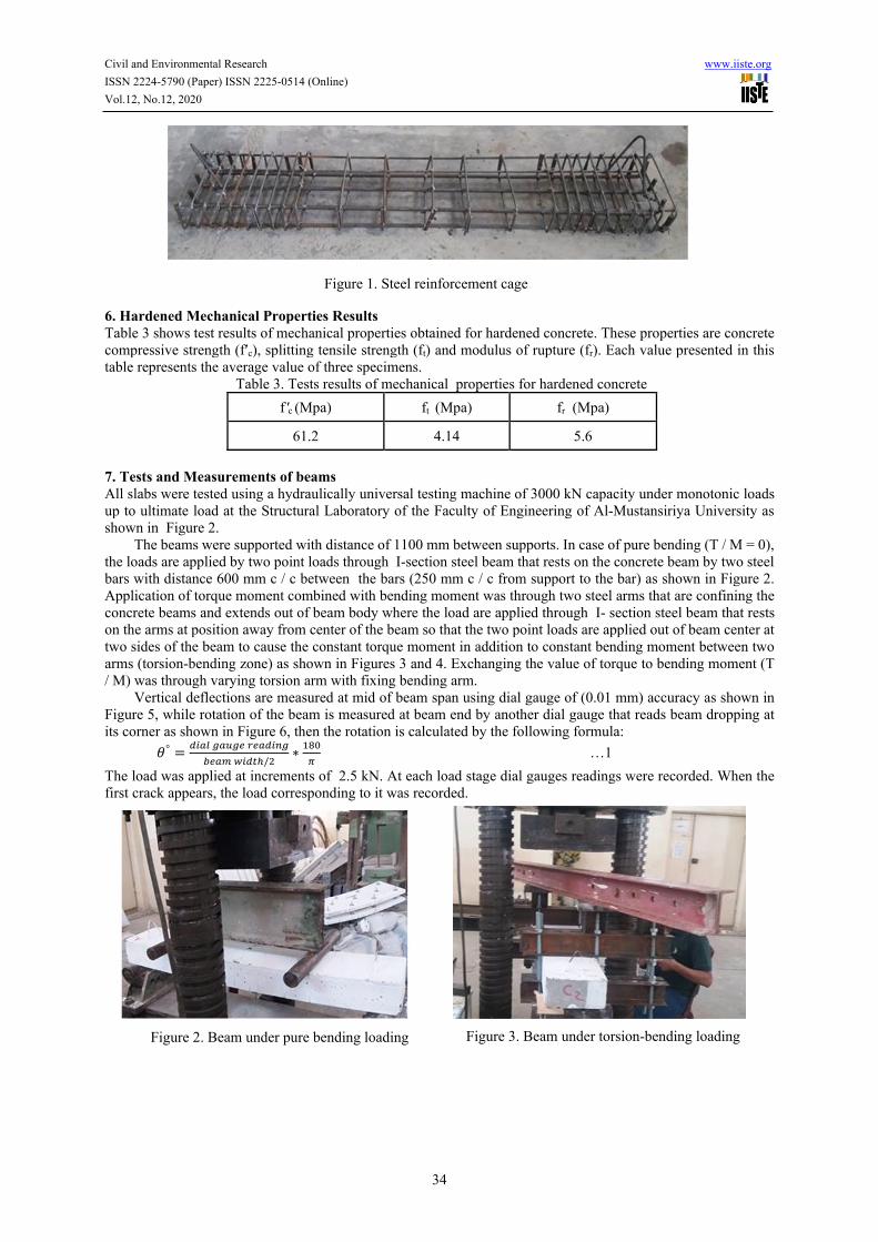
5.Steel Reinforcing Bars Deformed steel bars are used in this work with nominal diameters of 10 mm for longitudinal reinforcement in tension side (bottom side) and bars of diameter 6 mm are used for longitudinal reinforcement in compression side (top side) with stirrups of 5 mm with amounts detailed in Table 1. Longitudinal and transverse reinforcement are connected to make cages of the specimens as shown in Figure 1. The concrete cover for reinforced bars was 10 mm from all sides. The laboratory tensile tests on bars showed that the average yield stresses were 607 Mpa for 5 mm bars, 595 Mpa for 6 mm bars and 576 Mpa for 10 mm bars.
Civil and Environmental Research www.iiste.org
ISSN 2224-5790 (Paper) ISSN 2225-0514 (Online)
Vol.12, No.12, 2020
34
6. Hardened Mechanical Properties Results Table 3 shows test results of mechanical properties obtained for hardened concrete. These properties are concrete compressive strength (fʹc), splitting tensile strength (ft) and modulus of rupture (fr). Each value presented in this table represents the average value of three specimens.
Table 3. Tests results of mechanical properties for hardened concrete
fr (Mpa) ft (Mpa) f c (Mpa)
5.6 4.14 61.2
7. Tests and Measurements of beams All slabs were tested using a hydraulically universal testing machine of 3000 kN capacity under monotonic loads up to ultimate load at the Structural Laboratory of the Faculty of Engineering of Al-Mustansiriya University as shown in Figure 2.
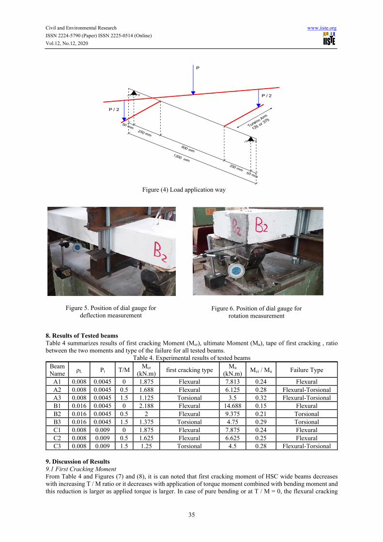
The beams were supported with distance of 1100 mm between supports. In case of pure bending (T / M = 0), the loads are applied by two point loads through I-section steel beam that rests on the concrete beam by two steel bars with distance 600 mm c / c between the bars (250 mm c / c from support to the bar) as shown in Figure 2. Application of torque moment combined with bending moment was through two steel arms that are confining the concrete beams and extends out of beam body where the load are applied through I- section steel beam that rests on the arms at position away from center of the beam so that the two point loads are applied out of beam center at two sides of the beam to cause the constant torque moment in addition to constant bending moment between two arms (torsion-bending zone) as shown in Figures 3 and 4. Exchanging the value of torque to bending moment (T / M) was through varying torsion arm with fixing bending arm.
Vertical deflections are measured at mid of beam span using dial gauge of (0.01 mm) accuracy as shown in Figure 5, while rotation of the beam is measured at beam end by another dial gauge that reads beam dropping at its corner as shown in Figure 6, then the rotation is calculated by the following formula:
𝜃°
/∗ …1
The load was applied at increments of 2.5 kN. At each load stage dial gauges readings were recorded. When the first crack appears, the load corresponding to it was recorded.
Figure 1. Steel reinforcement cage
Figure 2. Beam under pure bending loading
Figure 3. Beam under torsion-bending loading
Civil and Environmental Research www.iiste.org
ISSN 2224-5790 (Paper) ISSN 2225-0514 (Online)
Vol.12, No.12, 2020
35
8. Results of Tested beams Table 4 summarizes results of first cracking Moment (Mcr), ultimate Moment (Mu), tape of first cracking , ratio between the two moments and type of the failure for all tested beams.
Table 4. Experimental results of tested beams Beam Name
ρL Ρt T/M Mcr
(kN.m) first cracking type
Mu
(kN.m) Mcr / Mu Failure Type
A1 0.008 0.0045 0 1.875 Flexural 7.813 0.24 Flexural A2 0.008 0.0045 0.5 1.688 Flexural 6.125 0.28 Flexural-Torsional A3 0.008 0.0045 1.5 1.125 Torsional 3.5 0.32 Flexural-Torsional B1 0.016 0.0045 0 2.188 Flexural 14.688 0.15 Flexural B2 0.016 0.0045 0.5 2 Flexural 9.375 0.21 Torsional B3 0.016 0.0045 1.5 1.375 Torsional 4.75 0.29 Torsional C1 0.008 0.009 0 1.875 Flexural 7.875 0.24 Flexural C2 0.008 0.009 0.5 1.625 Flexural 6.625 0.25 Flexural C3 0.008 0.009 1.5 1.25 Torsional 4.5 0.28 Flexural-Torsional
9. Discussion of Results 9.1 First Cracking Moment From Table 4 and Figures (7) and (8), it is can noted that first cracking moment of HSC wide beams decreases with increasing T / M ratio or it decreases with application of torque moment combined with bending moment and this reduction is larger as applied torque is larger. In case of pure bending or at T / M = 0, the flexural cracking
Figure (4) Load application way
Figure 5. Position of dial gauge for deflection measurement
Figure 6. Position of dial gauge for rotation measurement

Civil and Environmental Research www.iiste.org
ISSN 2224-5790 (Paper) ISSN 2225-0514 (Online)
Vol.12, No.12, 2020
36
takes place before torsional cracking, whereas at T / M = 1.5, the torsional cracking takes place before flexural cracking. Maximum reduction in cracking moment was 40 % in case of beams has ρLn = 0.008 and ρt = 0.0045 when T / M varies from 0 to 1.5. Increasing longitudinal reinforcement ratio (ρL) slightly increases cracking moment capacity for all values of T / M as shown in Figure 6, while the transverse reinforcement ratio (ρt) approximately has not effect on cracking moment capacity as shown in Figure 7. 9.2 Ultimate Moments From Table 4, it can be noted that ultimate moment capacity (Mu) of HSC wide beams decreases with increasing T / M ratio or it decreases with application of torque moment combined with bending moment and this reduction is larger as applied torque is larger. This effect for torque or T / M ratio in reducing Mu is larger as longitudinal reinforcement ratio is larger and as transverse reinforcement ratio is smaller as shown in Figures 9 and 10.
From Figures 11 and 12 it is concluded that the relation between bending and torque moments is reversal, i.e as applied torque increases the bending moment capacity of the beam decreases and as bending moment increases the torsional capacity of the beam decreases. The slope of this relation is larger with increasing ρL and with decreasing ρt. This means that maximum beam capacity for bending moment is in case of pure bending (no torsion). 9.3 Cracking to Ultimate Moments Ratio From Table 4 it is seemed that cracking to ultimate moments ratio increases with increasing T / M ratio or with application torque moment combined with bending moment. This because of that the effect of torsion on ultimate moment capacity is larger than its effect on cracking moment capacity. This ratio decreases with increasing ρL and this decreasing is more pronounced when T / M ratio equals 0. Also, this ratio slightly decreases with increasing ρt and this decreasing is more pronounced when T / M ratio equals 1.5.
Figure 7. Effect of T / M ratio on
Mcr with varying ρL
Figure 8. Effect of T / M ratio on
Mcr with varying ρt
Figure 9. Effect of T / M ratio on
Mu with varying ρL
Figure 10. Effect of T / M ratio on
Mu with varying ρt

Civil and Environmental Research www.iiste.org
ISSN 2224-5790 (Paper) ISSN 2225-0514 (Online)
Vol.12, No.12, 2020
37
9.4 Failure Modes All beams subjected to pure bending moments (A1, B1 and C1) were failed by flexural mode. Although the beam (C2) was subjected to torque moment combined to bending moment (T / M = 0.5) but it was failed by flexural mode because of high transverse reinforcement ratio (ρt = 0.009) that increased torsional capacity for the beam and prevented torsional failure to happen.
The beam (C3) has the same ratio of transverse reinforcement for the beam (C2) but is failed by flexural-torsional mode that is combined of flexural failure and torsional failure. This type of failure was accident because of high applied torque moment value (T / M =1.5).
Also, Beams (A2 and A3) were failed by the flexural-torsional mode for the same reason especially that the transverse reinforcement ratio was not high (ρt = 0.0045) for them. Beams (B2 and B3) were failed by torsional mode due to high value of longitudinal reinforcement ratio (ρL = 0.016) that prevented incidence the flexural failure due to high flexural capacity of these beams especially that the transverse reinforcement ratio was not high (ρt = 0.0045). This failure type is more pronounced when ratio of T / M equals 1.5 as in beam (B3). These types of failures can be obviously marked from pictures of failed beams in Figure 13. 9.5 Crack Pattern Figure 13 shows the crack pattern for tested beams. In beams failed by flexural mode, the cracks are perpendicular to bending direction (vertical cracks). While the beams failed by torsional mode, the major cracks are inclined approximately by 45o with some vertical cracks due to flexural effects. The beams failed by flexural-torsional mode have both inclined cracks with degrees smaller than 45o and vertical cracks. The inclination of cracks increases with increasing T / M ratio. 9.6 Effect of Longitudinal Reinforcement Ratio (ρL) Figure 14 shows effect of increasing longitudinal reinforcement ratio (ρL) from 0.008 to 0.016 on bending moment capacity of HSC wide beams with varying T / M ratio. From this figure, it is noted that this increasing results in increasing in bending moment capacity (Mu) for all values of T / M. This effect is larger as T / M is smaller. Maximum increasing in (Mu) was in case of pure bending (T / M = 0) where it equals 88 %. While the smaller increasing was in case of high torque to moments ratio (T / M = 1.5) where it is equals 36 %.
Figure 11. Relation between bending and torque moments with ρL
Figure 12. Relation between bending and torque moments with ρt
i

Civil and Environmental Research www.iiste.org
ISSN 2224-5790 (Paper) ISSN 2225-0514 (Online)
Vol.12, No.12, 2020
38
9.7 Effect of Transverse Reinforcement Ratio (ρt) Figure 15 shows effect of increasing transverse reinforcement ratio (ρt) from 0.0045 to 0.009 on bending moment capacity of HSC wide beams with varying T / M ratio. From this figure, it is noted that this increasing does not affect the bending moment capacity (Mu) in case of pure bending (T / M = 0) where the resulting increase
Figure 13. Pictures of crack pattern for all tested wide beams Lift side pictures: Top and side faces of the beams
Right side pictures: Bottom faces of the beams

Civil and Environmental Research www.iiste.org
ISSN 2224-5790 (Paper) ISSN 2225-0514 (Online)
Vol.12, No.12, 2020
39
was about 1 %. This effect appears when torque moment are applied with bending moment ( T / M > 0) . This effect is larger as T / M is larger where maximum increasing in (Mu) was in case of T / M = 1.5 where it equals 29 %.
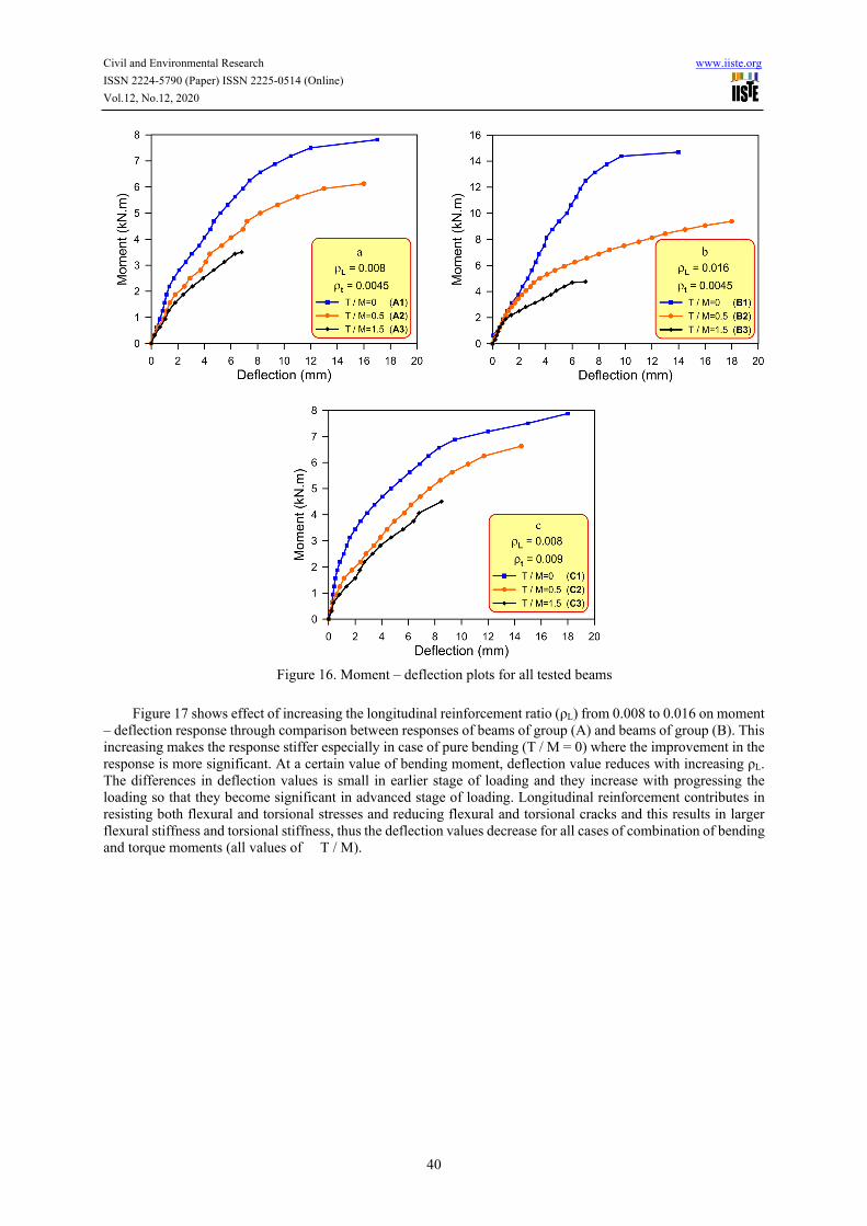
9.8 Moment – Deflection Response Figure 16 shows moment – deflection responses for all tested beams through three plots where each plot concerns to one group of these beams (Plot (a) for Group A, Plot (b) for Group B and Plot (c) for Group C). From plots of this figure one can note that the response is softer as T / M increases for all groups especially for beams of group B that have high longitudinal reinforcement ratio (ρL = 0.016). At a certain value of moment, deflection value increases with increasing T / M ratio. The differences in deflection values is small in earlier stage of loading and they increase with progressing the loading so that they become significant in advanced stage of loading. This behavior is due to application of torque moment combined with bending moment where the torque moment cause torsional cracks that increases with progressing the loading. The torsional cracks, allowance to flexural cracks, weaken beam stiffness and that makes the beam exhibits higher deflection values.
Figure 14. Effect of (ρL) on ultimate moment capacity (Mu)
Figure 15. Effect of (ρt) on ultimate moment capacity (Mu)
Civil and Environmental Research www.iiste.org
ISSN 2224-5790 (Paper) ISSN 2225-0514 (Online)
Vol.12, No.12, 2020
40
Figure 17 shows effect of increasing the longitudinal reinforcement ratio (ρL) from 0.008 to 0.016 on moment
– deflection response through comparison between responses of beams of group (A) and beams of group (B). This increasing makes the response stiffer especially in case of pure bending (T / M = 0) where the improvement in the response is more significant. At a certain value of bending moment, deflection value reduces with increasing ρL. The differences in deflection values is small in earlier stage of loading and they increase with progressing the loading so that they become significant in advanced stage of loading. Longitudinal reinforcement contributes in resisting both flexural and torsional stresses and reducing flexural and torsional cracks and this results in larger flexural stiffness and torsional stiffness, thus the deflection values decrease for all cases of combination of bending and torque moments (all values of T / M).
Figure 16. Moment – deflection plots for all tested beams
Civil and Environmental Research www.iiste.org
ISSN 2224-5790 (Paper) ISSN 2225-0514 (Online)
Vol.12, No.12, 2020
41
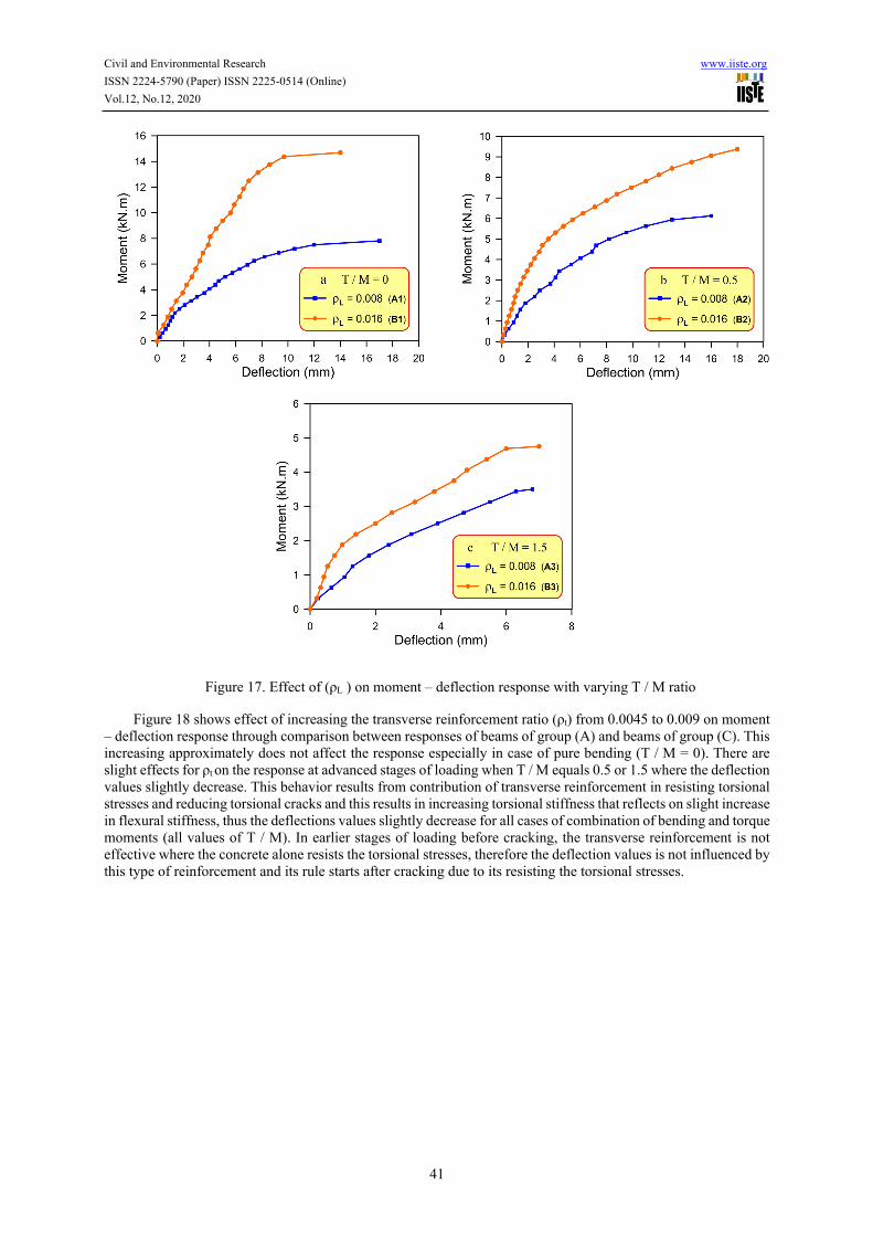
Figure 18 shows effect of increasing the transverse reinforcement ratio (ρt) from 0.0045 to 0.009 on moment
– deflection response through comparison between responses of beams of group (A) and beams of group (C). This increasing approximately does not affect the response especially in case of pure bending (T / M = 0). There are slight effects for ρt on the response at advanced stages of loading when T / M equals 0.5 or 1.5 where the deflection values slightly decrease. This behavior results from contribution of transverse reinforcement in resisting torsional stresses and reducing torsional cracks and this results in increasing torsional stiffness that reflects on slight increase in flexural stiffness, thus the deflections values slightly decrease for all cases of combination of bending and torque moments (all values of T / M). In earlier stages of loading before cracking, the transverse reinforcement is not effective where the concrete alone resists the torsional stresses, therefore the deflection values is not influenced by this type of reinforcement and its rule starts after cracking due to its resisting the torsional stresses.
Figure 17. Effect of (ρL ) on moment – deflection response with varying T / M ratio

Civil and Environmental Research www.iiste.org
ISSN 2224-5790 (Paper) ISSN 2225-0514 (Online)
Vol.12, No.12, 2020
42
9.9 Torque- Rotation Response Figure 19 shows Torque – rotation responses for beams subjected to torque moment combined with bending moment where each plot concern to one group of these beams (Plot (a) for Group A, Plot (b) for Group B and Plot (c) for Group C). From plots of this figure one can note that the response is stiffer as T / M increases for all groups especially for beams of group A that have smaller ratios of longitudinal and transvers reinforcement. At a certain value of Torque, rotation value increases with decreasing T / M ratio. The differences in rotation values are small in earlier stage of loading and they increase with progressing the loading so that they become significant in advanced stage of loading. With decreasing T / M ratio, bending moment is larger and this results in more flexural cracks that weaken beam flexural stiffness that reflects on decrease in torsional stiffness and this makes the beam exhibits higher rotation values.
Figure 20 shows effect of increasing the longitudinal reinforcement ratio (ρL) from 0.008 to 0.016 on torque – rotation response through comparison between responses of beams of group (A) and beams of group (B). This increasing makes the response stiffer for all values of T / M. At a certain value of torque, rotation value reduces with increasing ρL. The differences in rotation values are small in earlier stage of loading and they increase with progressing the loading so that they become significant in advanced stage of loading.
Figure 18. Effect of (ρt ) on moment – deflection response with varying T / M ratio

Civil and Environmental Research www.iiste.org
ISSN 2224-5790 (Paper) ISSN 2225-0514 (Online)
Vol.12, No.12, 2020
43
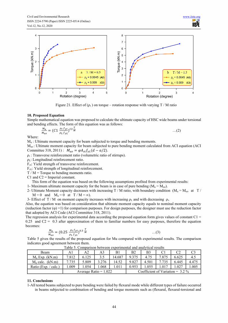
Figure 21 shows effect of increasing the transverse reinforcement ratio (ρt) from 0.0045 to 0.009 on torque –
rotation response through comparison between responses of beams of group (A) and beams of group (C). This increasing makes the response stiffer for both values of T / M. At a certain value of torque, rotation value reduces with increasing ρt. The differences in rotation values are very small in earlier stage of loading and they increase with progressing the loading so that they become significant in advanced stage of loading. From comparison between Figure 20 and Figure 21 it is noted that effect of longitudinal reinforcement on torque – rotation response is larger than effect of transverse reinforcement on this response for the adopted range of T / M ratios.
Figure 19. Torque – rotation plots for beams subjected to torque moment combined with bending moment
Figure 20. Effect of (ρL ) on Torque – rotation response with varying T / M ratio
Civil and Environmental Research www.iiste.org
ISSN 2224-5790 (Paper) ISSN 2225-0514 (Online)
Vol.12, No.12, 2020
44
10. Proposed Equation Simple mathematical equation was proposed to calculate the ultimate capacity of HSC wide beams under torsional and bending effects. The form of this equation was as follows:
𝐶1
…(2)
Where: Mu : Ultimate moment capacity for beam subjected to torque and bending moments. Muo : Ultimate moment capacity for beam subjected to pure bending moment calculated from ACI equation (ACI Committee 318, 2011) : 𝑀 𝜑𝐴 𝑓 𝑑 𝑎/2 . ρt : Transverse reinforcement ratio (volumetric ratio of stirrups). ρL: Longitudinal reinforcement ratio. Fyt: Yield strength of transverse reinforcement. FyL: Yield strength of longitudinal reinforcement. T / M = Torque to bending moments ratio. C1 and C2 = Imperial constant. This form of the equation was based on the following assumptions profited from experimental results: 1- Maximum ultimate moment capacity for the beam is in case of pure bending (Mu = Muo). 2- Ultimate Moment capacity decreases with increasing T / M ratio, with boundary condition (Mu = Muo at T /
M = 0 and Mu = 0 at T / M = ∞). 3- Effect of T / M on moment capacity increases with increasing ρL and with decreasing ρt.
Also, the equation was based on consideration that ultimate moment capacity equals to nominal moment capacity (reduction factor (φ) =1) for comparison purposes. For design purposes, the designer must use the reduction factor that adopted by ACI Code (ACI Committee 318, 2011). The regression analysis for experimental data according the proposed equation form gives values of constant C1 = 0.25 and C2 = 0.3 after approximation of them to familiar numbers for easy purposes, therefore the equation becomes:
0.25
. …(3)
Table 5 gives the results of the proposed equation for Mu compared with experimental results. The comparison indicates good agreement between them.
Table 5. Comparison between experimental and analytical results Beam A1 A2 A3 B1 B2 B3 C1 C2 C3
Mu Exp. (kN.m) 7.812 6.125 3.5 14.687 9.375 4.75 7.875 6.625 4.5 Mu calc. (kN.m) 7.735 5.809 3.276 14.52 9.827 4.501 7.735 6.445 4.475
Ratio (Exp. / calc.) 1.009 1.054 1.068 1.011 0.953 1.055 1.017 1.027 1.005 Average Ratio = 1.022 Coefficient of Variation = 3.2 %
11. Conclusions 1-All tested beams subjected to pure bending were failed by flexural mode while different types of failure occurred
in beams subjected to combination of bending and torque moments such as (flexural, flexural-torsional and
Figure 21. Effect of (ρt ) on torque – rotation response with varying T / M ratio
Civil and Environmental Research www.iiste.org
ISSN 2224-5790 (Paper) ISSN 2225-0514 (Online)
Vol.12, No.12, 2020
45
torsional modes). Failure of the beams tends to move from flexural mode into torsional mode as T / M increases, as longitudinal reinforcement ratio (ρL) increases and as transverse reinforcement ratio (ρt) decreases.
2- Crack pattern develops in vertical manner in case of pure bending. Presence of torque moment combined to bending moment causes some inclined cracks. As T / M ratio increases number of inclined cracks is larger and their inclination is larger.
3- First cracking moment decreases with increasing T / M ratio and slightly increases with increasing (ρL), while it does not influenced by increasing (ρt).
4- Ultimate moment capacity significantly decreases with increasing T / M ratio. This effect for T / M ratio is larger with increasing (ρL) and is smaller with increasing (ρt).
5- The relation between bending and torque moments is reversal. The slope of this relation is steeper with increasing (ρL) and with decreasing (ρt).
6- Increasing (ρL) from 0.008 to 0.016 causes significant increase in ultimate moment capacity. This effect is larger as T / M decreases with maximum increasing (88 %) in case of pure bending.
7- Increasing (ρt) from 0.0045 to 0.009 does not affect ultimate moment capacity in case of pure bending but its effect appears in case of combination of bending and torque moments. This effect is larger as T / M increases with maximum increasing (29 %) when T / M = 1.5.
8- Moment-deflection response is softer as T / M increases especially in case of high longitudinal reinforcement ratio (ρL = 0.016). The differences in deflection values larger with progressing the loading. Increasing (ρL) makes this response stiffer especially in case of pure bending whereas increasing (ρt) slightly stiffens this response in advanced loading stages for high values of T / M.
9- Torque-rotation response is stiffer as T / M increases. In earlier loading stages the rotation differences are very small but they become large in advanced stages of loading. Also increasing (ρL) make the responses stiffer for all values of T / M and increasing (ρt) make it slightly stiffer in advanced loading stages.
10- The proposed empirical expression for calculation of ultimate moment capacity of HSC wide beams has good agreement with experimental results with average equals 1.022 and COV equals 3.2 %.
References ACI Committee 318, 2011, “Building Code Requirements for Structural Concrete, (ACI 318M-11) and
commentary (318R-11),” American Concrete Institute, Farmington Hills, Michigan, USA, 503 pp. Haido, J. H. and Musa, I.H., 2013, “Cracking Strength of Steel Fiber Reinforced Concrete Shallow Wide Beams
Under Impact Actions,” International Journal of Scientific & Engineering Research. ,Vol.4, Issue 4, April, pp. 464-472.
Kheder, G.F., Waryosh, W.A., and Rashid, A.F., 2005, “Bond Behaviour for Normal and High Strength Concrete,” Journal of Engineering and Development, Vol.9, No.4, December, pp.99-119.
Lantsoght, E. O. L., Veen, C. V. D., Boer, A. D. and Walrvan, J. C., 2014, “Influence of Width on Shear Capacity of Reinforced Concrete Members,” ACI Structural Journal, Vol. 111, NO.6, pp. 1441-1450.
Lotfy, E. M., Mohamadien, H. A. and Hassan, H. M., 2014, “Effect of Web reinforcement on Shear Strength of Shallow Wide Beams,” International Journal of Engineering and Technical Research, Vol. 2, Issue 11, pp. 98-107.
Mohammadyan –Yasouj, S. E., Marsono, A. K., Abdulah, R. and Moghadasi, M., 2015, “Wide Beam Shear Behavior with Diverse Types of Reinforcement,” ACI Structural Journal, Vol. 112, NO.2, pp. 199-208.
Said, M. and Elrakib, T.M., 2013, “Enhancement of Shear Strength and Ductility for Reinforced Concrete Wide Beams Due to Web Reinforcement,” HBRC Journal, No.9, pp. 235-242.
Sherwood, E. G., Lubell, A. S., Bentz, E.C. and Collins, M.P., 2006, “One-Way Shear Strength of Thick Slabs and Wide Beams,” ACI Structural Journal, Vol. 103, NO.6, pp. 794-802.
Shuraim, A. B. and Al-negheimish, A. I., 2011, “Design Consideration for Joist Floor with Wide – Shallow Beams,” ACI Structural Journal, Vol. 108, NO.2, pp. 188-196.