enhancing the performance of piezoelectric mems · pdf file · 2017-04-04enhancing...
TRANSCRIPT

Enhancing the Performance of Piezoelectric MEMS Accelerometer
For
Professor D. Prescott Associate Professor
American University of Sharjah Sharjah, UAE
by Saeed Nusri Walid Diab
Shaikha Al Kendi Basel Zam
January 13, 2011

PiezoelectricMEMSAccelerometer 2
Executive Summary
This report examines the drawbacks of a conventional Piezoelectric MEMS
Accelerometer and proposes ideas about how its design can be improved to increase its
efficiency and broaden its potential range of applications. The report also covers a brief
background about accelerometer, including its operation and applications.
The current accelerometer contains certain problems that have been discussed in this
report. These problems include the current spring design, the weakness of the piezoelectric signal
and the noise incurrence due to temperature variations and vibrations.
Correspondingly, five solutions have been proposed that will enhance the performance of
the Piezoelectric MEMS Accelerometer. Four of these include the choice of piezoelectric
ceramics, a new spring design called the fold spring, the use of rubber coated ceramics as
housing, the addition of a Whetstone Bridge and a filter to reduce temperature and vibration
effects and the use of amplifiers to amplify the piezoelectric charge. Additionally, the
implementation of software programming called Very Long Instruction Word (VLIW) that aims
to reduce the response time has been discussed.
The proposed solutions are evaluated, while paying close attention to cost effectiveness.
This evaluation is included as a separate section of this report. The report concludes with
recommendation that will enhance the performance of the Piezoelectric MEMS Accelerometer in
an approach that is practical and cost effective.
PiezoelectricMEMSAccelerometer 3
TableofContents
ExecutiveSummary......................................................................................................................................2
ListofFigures...............................................................................................................................................4
ListofTables.................................................................................................................................................4
1.0 Introduction......................................................................................................................................5
1.1 Purpose of the Report.........................................................................................................................5
1.2 General Introduction...........................................................................................................................5
1.3 Situation.............................................................................................................................................7
2.0 Problem Statements and Solutions...................................................................................................7
2.1 Piezoelectric Material.........................................................................................................................7
2.2Theuseofsprings...............................................................................................................................8
2.3 Environmental Factors.....................................................................................................................12
2.4NoiseSegregation.............................................................................................................................14
2.5 Application of Amplifiers.................................................................................................................16
2.6 Software Implementation.................................................................................................................17
3.0 Evaluation.......................................................................................................................................20
4.0 Conclusion......................................................................................................................................21
5.0 Recommendations.........................................................................................................................22
6.0 References......................................................................................................................................23
7.0 Appendices.....................................................................................................................................25

PiezoelectricMEMSAccelerometer 4
List of Figures
Figure Name Page 1 Bending Spring 8 2 Torsion Spring 8 3 Tensile Spring 8 4 Bending Spring Equation 9 5 Torsion Spring Equation 10 6 Tensile Spring Equation 10 7 Fold Spring 11 8 Fold Spring Equation 11 9 Natural Frequency Equation 12 10 Wheatstone Bridge 13 11 Active filter output voltage 14 12 Amplifier 15 13 DAC 16 14 Processing using VLIW 17
List of Tables
Table Name Page
1 Modulus of Elasticity 9
2 Equation Notations 10

PiezoelectricMEMSAccelerometer 5
1.0 Introduction
1.1 Purpose of the Report
This report examines the basic problems of a conventional Piezoelectric MEMS
accelerometer and how its design can be improved to increase its efficiency and broaden its
potential range of applications. The problems discussed in this report relate to the current spring
design, the weakness of the piezoelectric signal and noise incurrence that occurs due to
temperature variation and vibration.
Correspondingly, the proposed solutions are; the choice of piezoelectric ceramics, the
new spring design called the fold spring, the use of rubber coated ceramic for the housing, the
Whetstone Bridge and filter addition to reduce the temperature and vibration effect, the use of
amplifier to amplify the piezoelectric charge and the software implementation of Very Long
Instruction Word programming technique to reduce the response time.
1.2 General Introduction
Micro electro mechanicals systems (MEMS) are devices that consist of components that
measure between 1 to 100 micrometers in size. These micro systems, which are produced using
state of the art technique of micro fabrication, consist of two basic components: an actuating or a
sensing element and a processing unit. According to Dr. Hsu [1] of Jan Jose University, the small
size of these micro systems not only reduces their cost of production but also makes them less
viable to problems caused by thermal distortion and vibration. Also, the effect of gravity and
inertia is no longer important because of their negligible mass. These features endlessly increase
PiezoelectricMEMSAccelerometer 6
the potential of MEMS technology and place them at the pinnacle of modern industrial
applications.
Piezoelectric MEMS accelerometer is a micro scale sensor that is used to measure
acceleration. In general, micro sensors are built to sense the existence and the intensity of a
certain physical, chemical or biological quantities such as temperature, pressure force, sound,
light, nuclear radiation, magnetic flux and chemical compositions [1]. In this case, the sensor is
designated to measure acceleration forces. These forces can either be static, like the gravitational
acceleration force, or dynamic such as the forces exerted by a moving or a vibrating body [2].
The accelerometer appears in daily commercial products. A common example would be
its use in smart phones where accelerometer measures the movement of the device relative to the
gravitational acceleration and rotate the display of the screen to the convenience of the user. It is
also used in still cameras for image stabilization and anti blur capturing. By detecting the
movement of the camera it prevents the CCD shutter from snapping to prevent blur. Another use
of accelerometer appears in a device called foot pod, which athletes use to measure their speed of
travel of the distance they have covered [3].
The core of a MEMS accelerometer consists of a central mass that moves in response to
its acceleration. This inertial mass is mounted on a cantilever spring that limits its movements
and returns to its central position when it is at rest. A single piezoelectric crystal, which
characteristically produces a voltage under pressure, is attached at the end of the cantilever
spring such that when the mass moves the crystal compresses producing the voltage accordingly.
The force caused by vibration or a change in motion causes the mass to compress the
piezoelectric material which produces an electrical charge that is proportional to the force

PiezoelectricMEMSAccelerometer 7
exerted upon it. Since the charge is proportional to the force, and the mass is constant, then the
charge is proportional to the acceleration. This charge is collected as a voltage by the
measurement instrument and the required output is generated [4].
The use of MEMS accelerometer in the deployment of airbags in modern vehicles can be
used to illustrate this entire operation. In a vehicle crash situation, there is a sudden change in the
acceleration of the vehicle. This unsafe deceleration is detected by the component of the
accelerometer and signal collected by measurement instrument is processed and the air bags are
deployed. The whole process takes only a fraction of second. Earlier systems needed many
mechanical and electrical components that had to be located throughout an automobile for
measuring same data. But MEMS accelerometer, which consists of only microscopic chips, has
efficiently and cost effectively replaced these systems [4].
1.3 Situation
Since Piezoelectric MEMS Accelerometer is a recent engineering innovation it has a
wide scope of improvement in its design for achieving optimum efficiency and broadening its
range of applications. This report discusses the issues of a conventional Piezoelectric MEMS
Accelerometer and how its design can be improved for optimum performance.
2.0 Problem Statements and Solutions
2.1 Piezoelectric Material
The choice of piezoelectric material is the most integral step in the design the
accelerometer because it is the core element that produces the input signal. There are two main
categories of piezoelectric material. The first is the single crystal material which is usually

PiezoelectricMEMSAccelerometer 8
quartz. These crystals have a long life span in terms of sensitivity, but they are generally less
sensitive than the other category, the piezoelectric ceramic. Piezoelectric ceramic have a high
sensitivity and are inexpensive to produce than the crystal derivatives. Compounds such barium
titinate, lead zirconate, lead titanate and lead metabionate are mixed in various compositions to
produce the piezoelectric ceramic [5].
The conventional accelerometer uses either of the two categories. But considering that
response time is one of the main factors that determine the efficiency of the accelerometer, using
piezoelectric ceramic would be more feasible, since they are more sensitive than piezoelectric
crystal. Moreover, due to their lower cost of production they are much more cost effective.
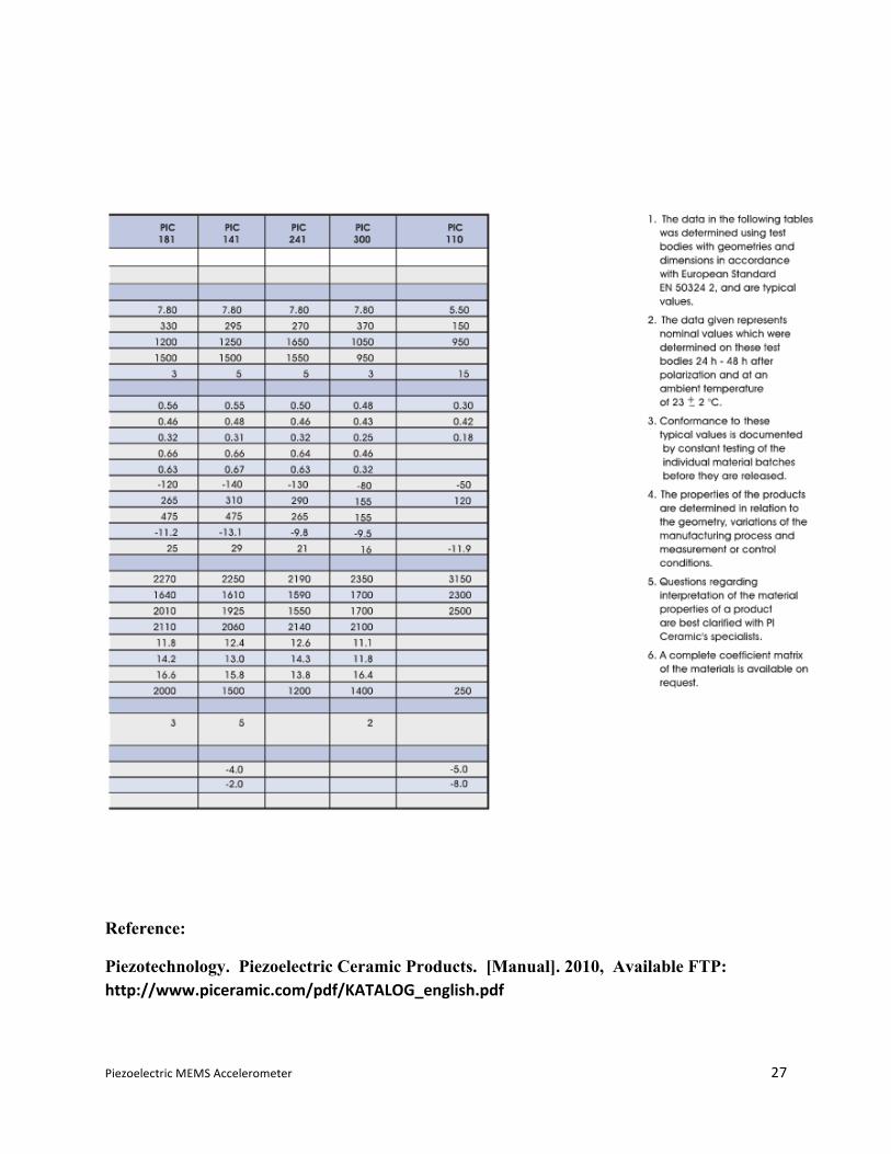
Piezoelectric ceramic materials can appear in a wide range of selections, based on the
composition of lead zirconate titinate (PZT) and barium titanate. By combining these compounds
in the right proportion, a piezoelectric ceramic material can be produced that would best suited
for its application in the accelerometer (See Appendix A for properties of different piezoelectric
ceramic materials).
2.2Theuseofsprings
Typically, the term conventional spring depicts the picture of a helical kind that is often
used in vehicles, as shock absorbers, and in mattresses. However, engineers have a much broader
definition of conventional springs which includes various types suited for different applications.
These types of springs, including the helical one, can be simply listed as the bending type, the
torsion type and the tensile type. All these categories follow the basic principle of a spring,
which is to store mechanical energy. However, the main difference between these springs comes

PiezoelectricMEMSAccelerometer 9
in the direction of their deformation that determines their function and application. For example,
in bending springs, the force applied at the far end of the fulcrum causes it to deform
perpendicularly to the longitudinal axis. In torsion springs, the applied force causes a rotational
deformation (twist) to the spring while in tensile springs it causes lateral deformation in the axial
direction [6].
Figures 1-3 illustrate the different types of springs and their direction of deformation.
F
F F
Figure 1: Bending Spring [7]
Figure 2: Torsion Spring [8]
Figure 3: Tensile Spring [9]

PiezoelectricMEMSAccelerometer 10
Several factors have to be considered while selecting the spring so that it is best suited for
the required application. One of these factors is the spring stiffness, which is symbolized by the
letter ‘K’. The spring stiffness correspondingly depends on other variables, such as the length,
the orientation, the geometry and the elasticity of the material. Another property, the modulus of
elasticity, represents the ability of the material to maintain its rigidity and structure without
permanent deformation. Modulus of elasticity is denoted by the letter ‘E’. The following table
illustrates the empirical values of modulus of elasticity for different metals.
Metal GPa Aluminum 69
Brass 97 Copper 110
Magnesium 45 Nickel 207 Steel 207
Titanium 107 Tungsten 407
Table 1: Modulus of Elasticity [10]
Figures 4-6 illustrate the equations that are used for calculating the spring stiffness for the
different types of springs previously mentioned. Respectively, Table 2 illustrates the notations
used in each equation.
K = 3 ∗ E ∗ IL!
Figure 4: Bending Spring Equation [6]

PiezoelectricMEMSAccelerometer 11
𝐾 = 𝐺 ∗ ℎ ∗ 𝑏!
𝐿 ∗ 13− 0.21 ∗
𝑏ℎ 1−
𝑏!
12 ∗ ℎ!
Figure 5: Torsion Spring Equation [6]
K = E ∗ b ∗ h
L
Figure 6: Tensile Spring Equation [6]
Table 2 - Equation notation [6]
The current design of the Piezoelectric MEMS Accelerometer uses a bending spring to
measure the acceleration of the system. However, using this type of spring induces errors,
causing the piezoelectric material to produce a false signal that does not correspond to the real
acceleration that takes place. Therefore, a new spring design has been proposed that uniquely
combines all three of the previously mentioned categories of springs. The new design will be
E = Modulus of Elasticity
I =
! ∗ !!
!"
G =
A material property that is related to the stress resulting from the applied force (Published in Tables) [1]
b = Geometrical Base
h
= Geometrical Height
L = Length
K = Spring Stiffness

PiezoelectricMEMSAccelerometer 12
able to efficiently measure the system’s actual acceleration and transfer it to the piezoelectric
material. [6]
The new spring design is called the fold spring. This spring, counter acts in the direction
in which the acceleration is applied, as illustrated in Figure 7.
Figure 7: Fold Spring [6]
in which the stiffness of elasticity is given by the equation in figure 8.
K = 12 ∗ E ∗ I
L!
Figure 8: Fold Spring Equation. [6]
2.3 Environmental Factors
The Piezoelectric MEMS Accelerometer experiences a number of environmental factors
that affect its performance and life span. The first factor is the variation in temperature from the
surrounding medium. The presence of this factor, affects both the functionality and sensitivity of
the piezoelectric material which causes it to produce redundant error in the output signal. This
PiezoelectricMEMSAccelerometer 13
can be misinterpreted by the integrated circuit as an actual acceleration, when, in reality, no
physical acceleration takes place [11].
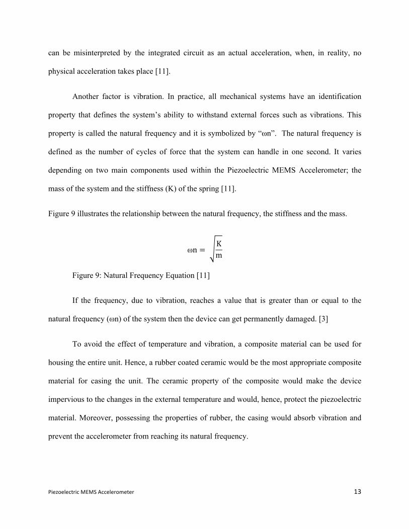
Another factor is vibration. In practice, all mechanical systems have an identification
property that defines the system’s ability to withstand external forces such as vibrations. This
property is called the natural frequency and it is symbolized by “ωn”. The natural frequency is
defined as the number of cycles of force that the system can handle in one second. It varies
depending on two main components used within the Piezoelectric MEMS Accelerometer; the
mass of the system and the stiffness (K) of the spring [11].
Figure 9 illustrates the relationship between the natural frequency, the stiffness and the mass.
ωn = Km
Figure 9: Natural Frequency Equation [11]
If the frequency, due to vibration, reaches a value that is greater than or equal to the
natural frequency (ωn) of the system then the device can get permanently damaged. [3]
To avoid the effect of temperature and vibration, a composite material can be used for
housing the entire unit. Hence, a rubber coated ceramic would be the most appropriate composite
material for casing the unit. The ceramic property of the composite would make the device
impervious to the changes in the external temperature and would, hence, protect the piezoelectric
material. Moreover, possessing the properties of rubber, the casing would absorb vibration and
prevent the accelerometer from reaching its natural frequency.

PiezoelectricMEMSAccelerometer 14
2.4NoiseSegregation
When the piezoelectric material compresses under the force of the mass, it produces a
charge or a voltage which is registered by the integrated circuit as a signal. Sometimes, this
signal can incur noise which can lead to a false response by the system. For instance,
accelerometers used in vehicles can deploy airbags without any accident actually occurring
because of noise. Hence, noise has to be eliminated.
Noise can be introduced in the signal by many external factors, like temperature variation
and vibration. The noise causes distortion in such a way that false harmonics get introduced and
eventually become part of the desired signal. This means that if the signal is altered due to noise,
the system will return a faulty response. Moreover, the noise incurred by the signal is inversely
proportional to its strength, such that weaker signal is more prone to carry noise than a stronger
one. To overcome this issue, a Wheatstone Bridge along with active filters can be used.
Wheatstone Bridge is widely used in monitoring sensing devices. In Piezoelectric
MEMS Accelerometer it can be used for eliminating temperature variation. The circuit
configuration of Wheatstone Bridge is
shown in Figure 10.
Figure 10: Wheatstone Bridge[12].

PiezoelectricMEMSAccelerometer 15
The Wheatstone Bridge consists of two parallel branches that have two resistors in series.
The output voltage is taken from two nodes in the middle of the two adjacent resistors in both
sides. Whereas the input signal is fed to the circuit from the top node, and the bottom one is
grounded. This diamond shape configuration allows the Wheatstone Bridge to change its internal
resistance according to a specific level of temperature. Therefore, it serves as a balancer and
minimizes the deviation of the input signal from the signal produced by the piezoelectric material
[13].
To prevent the noise caused by vibration, an active filter can be used to purify the desired
signal. A filter is a device that passes electric signals at a certain range of frequencies while
preventing the remaining frequencies to pass.
A typical output voltage signal from an active filter is shown in Figure11.
Figure 11: Active filter output voltage [14]
PiezoelectricMEMSAccelerometer 16
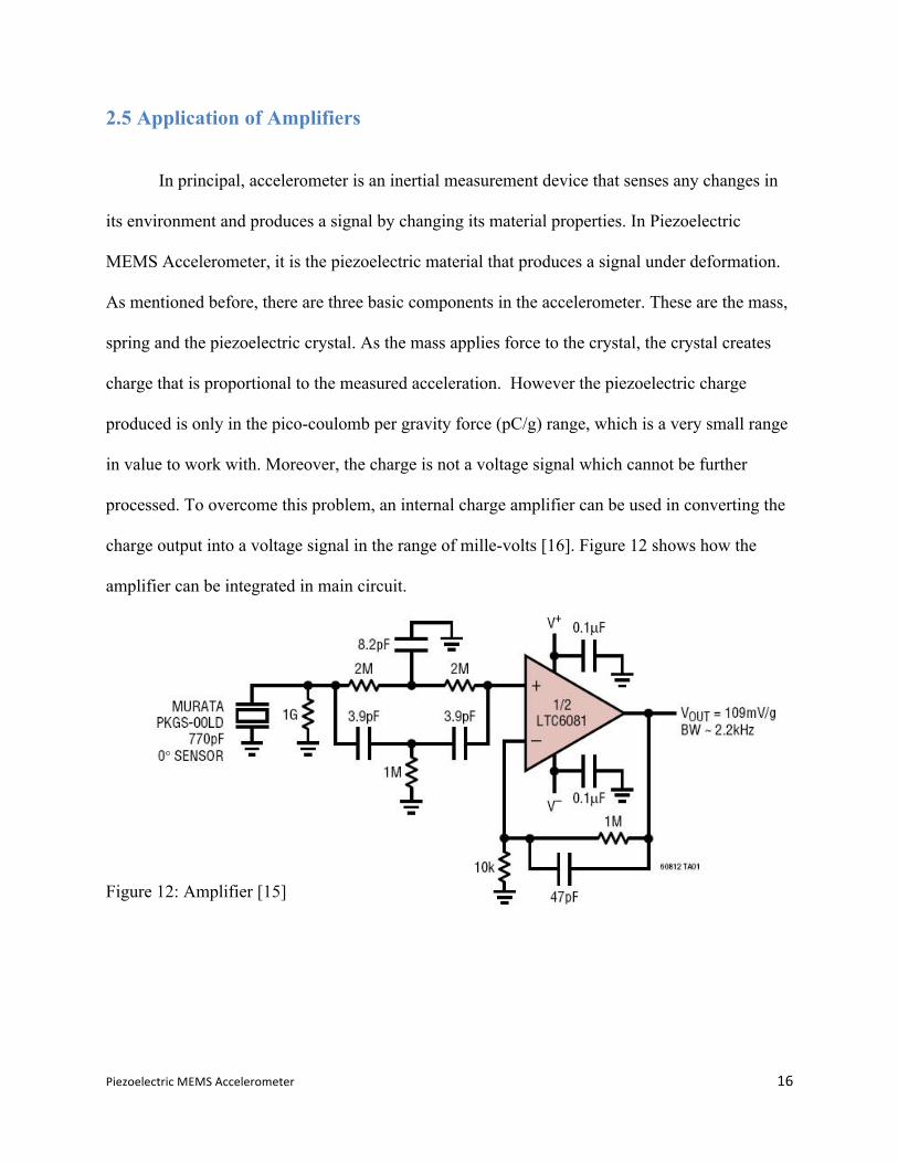
2.5 Application of Amplifiers
In principal, accelerometer is an inertial measurement device that senses any changes in
its environment and produces a signal by changing its material properties. In Piezoelectric
MEMS Accelerometer, it is the piezoelectric material that produces a signal under deformation.
As mentioned before, there are three basic components in the accelerometer. These are the mass,
spring and the piezoelectric crystal. As the mass applies force to the crystal, the crystal creates
charge that is proportional to the measured acceleration. However the piezoelectric charge
produced is only in the pico-coulomb per gravity force (pC/g) range, which is a very small range
in value to work with. Moreover, the charge is not a voltage signal which cannot be further
processed. To overcome this problem, an internal charge amplifier can be used in converting the
charge output into a voltage signal in the range of mille-volts [16]. Figure 12 shows how the
amplifier can be integrated in main circuit.
Figure 12: Amplifier [15]

PiezoelectricMEMSAccelerometer 17
2.6 Software Implementation
Execution of a large number of operations in the central processing requires more
performance and time.The time needed for the processor to complete executing its instructions
increases the response time for the output to be generated at the required time. This causes delay
in the entire system. Using a Digital Signal Processor (DSP) is a suitable solution when a set of
mathematical operations requires efficient execution. Usually the purpose of DSP is to filter and
calculate the analog signal. It receives an analog signal from the sensor and converts it into
digital signal using analog-to-digital convertor (ADC). The central processing unit will be able
then to process the digital data before converting it again into an analog signal using a digital to
analog convertor (DAC), as depicted by Figure 13. However, the DSP is not efficient in term of
executing large number of instructions because it executes them sequentially. As a result, the
processor will use its resources inefficiently leading to poor performance.
Figure 13: DAC [17]
Before executing, the processor must check for independency of every instruction and
confirm that there are no independent instructions in the program. For example, an instruction’s
output is used as an input for the next instruction. Logically, these instructions cannot be
executed at the same time, and the first instruction must get executed first. The scheduling
hardware of the processor handles the determination of interdependencies and the arrangement of
instructions.

PiezoelectricMEMSAccelerometer 18
There are two main methods of scheduling. A sequential scheduler receives a list of
sequential instructions and then it makes the decision of which instruction can get executed in
the functional unit of the processor at any instant. Actually, this method works fine, but it
requires the processor to do huge scheduling work. As a sequence, the processor’s scheduler
will require more transistors to handle the scheduling task which goes against the purpose of
integrating the circuits of the processor to get higher speed.
The performance of the DSP can be improved by using a technique called Very Long
Instruction Word (VLIW) where the processor executes different sub-steps of sequential
instructions simultaneously rather than sequentially. In the A VLIW processor, the task of
instruction reordering and scheduling is assigned to the compiler, a software that translates a
program written in a high-level programming language, like C/C++, COBOL, into machine
language [18] . The processor will then execute instruction it receives from the compiler as fast
as possible (See Appendix B for examples of VLIW software architecture). In other words, a
VLIW compiler groups the instructions and sends them to the processor as fixed-length packets.
This process is illustrated by Figure 14.
Figure 14: Processing using VLIW [19]
PiezoelectricMEMSAccelerometer 19
The essential advantage of using VLIW is that the processor doesn't have to consume
its hardware power on instructions scheduling and arrangement. VLIW simply reduces the
complexity of the hardware and increases the complexity of software. Actually, this trade-off has
a significant benefit because the compiler can be rewritten instead of redesigning the chip
therefore; the complexity is paid for only once. One of the available advantages is having smaller
chips, which leads to higher profits for the producers and cheaper prices for the users. Dealing
with complexity in a software design is much easier than in a hardware design, therefore, the
chip costs less to design, is faster to design, and requires less debugging, checking for errors,
which make the design process cheaper. Also, the compiler can be improved after the chip has
been made-up [20]
However, the problem with this technique is that it can cause a significant code bloat, is the
production of code that is perceived as unnecessarily long, slow, or otherwise wasteful of
resources [18]. In a the VLIW structure, the instruction packets are a fixed size, therefore when
there is no enough instructions to fill up the packets, the compiler inserts NOPS, an assembly
language instruction, sequence of programming language statements, or computer protocol
command that does nothing at all [18], in the empty spots of the packet.
A solution of this problem is encoding fewer operations than the number of available
functional units in the processor. For example a VLIW machine with ten execution units but only
5 operations can described in these units. Each operation will have unit number to specify the
execution unit that the operation should be sent to. As a result, of that the processor will use its
resources efficiently. However, this solution prevent the processor from maximizing the number
the operation that the processor can execute. To prevent the problem of limiting performance, the

PiezoelectricMEMSAccelerometer 20
number of the operation allowed to be executed can be decided based on analysis of program
behavior [20]
3.0 Evaluation
The use of piezoelectric ceramic as previously proposed is a more feasible solution than
the piezoelectric crystal because the ceramic materials are more sensitive and cost effective.
However, their life span is much less than piezoelectric crystal which makes them ineffective in
applications which are long-lasting. For example, airbag deployment system that uses a
piezoelectric crystal in its accelerometer would be more dependable than the one that uses the
piezoelectric ceramic, provided that both the vehicles are of equally old.
The implementation of the new spring design, which was discussed earlier, is neither
time efficient nor cost effective. However, the fold spring does significantly increase the
performance of the system. The compromise between the performance enhancement and the
price of the device depends on the application. For example in aircrafts, high performance is
required to measure the acceleration precisely and this incurs high cost.
While considering the solutions proposed for noise segregation, it should be noted that
active filters are difficult to implement. Low noise segregation is a sensitive procedure and any
factor that affects the process cannot be excluded. Moreover, since it is time consuming to
determine the criteria that are desired for the choice of appropriate active filters, the solution is
likely to incur high implicit cost of time. However, the implementation is necessary to minimize
noise while maintaining the highest accuracy in the shortest response time. On the other hand,
the use of the Wheatstone Bridge and the amplifier, are both cost effective. Their cost might

PiezoelectricMEMSAccelerometer 21
increase depending on fabrication and size; the smaller the size of the accelerometer the higher
the cost.
The employment of rubber coated ceramics that are used for housing the accelerometer,
is indeed a highly cost effective method of shedding the effect of temperature variations and
vibrations. However, it is not as efficient as the implementation of the Wheatstone Bridge and
the active filters. Hence, the utilization of rubber coated ceramics can be excluded from the
design for cost reduction.
Finally, according to Dr. Gad-el-Hak [21], a professor at the Virginia Commonwealth
University, “Three primary areas that are considered in micro machined devise applications
include packaged volume or size, system cost and performance often these three drivers cannot
be met in a single technology choice”. This highlights that tradeoffs would have to be made in
size and cost while decreasing the efficiency of the accelerometer.
4.0 Conclusion
Overall, this report covers brief background information on accelerometers that explains
its fundamental operation and how it is being extensively used in daily products. Next, the report
states the situation which stimulates the need for a better and a more efficient design of
accelerometers. Then, the problems and respective solutions have been discussed. These
solutions include the choice of piezoelectric ceramic, the new spring design, the design of the
casing, the method of noise segregation, the application of filters and software implementation.
Finally, the solutions have been evaluated based on their feasibility and cost effectiveness.

PiezoelectricMEMSAccelerometer 22
5.0 Recommendations
1. The new design of Piezoelectric MEMS Accelerometer should include piezoelectric
ceramic instead of a single crystal piezoelectric crystal. This recommendation is
supported by the assumption that most applications of accelerometers do not live
long enough to drastically affect the sensitivity of the ceramic.
2. Fold spring should be included in the new design because it significantly enhances
the efficiency of the accelerometer, which outweighs the additional implementation
cost.
3. Though active filters involve high implicit cost of time, they should be present in the
design because of their importance in the noise segregation process.
4. Wheatstone Bridge and amplifiers are necessary for noise reduction due to
temperature variations and vibrations and should be present in the design, especially
if the rubber coated ceramic housing is not being included for cost reduction.
5. A DSP should be designed with VLIW technique where encoded functions are less
than the number of available functional units in the processor. Also the number of the
operation allowed to be executed can be decided based on analysis of program
behavior.

PiezoelectricMEMSAccelerometer 23
6.0 References
[1] T. R. Hsu. MEMS & Microsystems: Design and Manufacture. Avenue of the Americas, NY: McGraw-Hill Companies Inc., 2002.
[2] Texas Instrument. Accelerometers And How They Work. [Presentation]. 2005, Available FTP: http://www2.usfirst.org/2005comp/Manuals/Acceler1.pdf
[3] Wikipedia, "Accelerometer," n.d., http://www.useit.com/papers/heuristic/heuristic_list.html.
[4] MEMS Industry Group, An Introduction To MEMS. [Documentary]. Available FTP: http://www.youtube.com/watch?v=CNmk-SeM0ZI
[5] A. Safari and K. Akdogan, Piezoelectric and Acoustic Materials for Transducer Application. Spring Street, NY: Springer Science + Business Media LLC., 2008. [E-book] Available: SpringerLink e-book.
[6] V. Kaajakari, Practical MEMS. Las Vegas, NV: Small Gear Publishing, 2009.
[7] S.Z. Elgun, “Modulus of Elasticity Experiment,”2000, http://info.lu.farmingdale.edu/depts/met/met206/modulus.html
[8] S. J. Record, “The Mechanical Properties of Wood,” 1914, http://chestofbooks.com/home-improvement/woodworking/Mechanical-Properties-of-Wood/Toughness-Torsion.html
[9] WEAVE, “Module 2: Tensile Test,” 2003, http://dolbow.cee.duke.edu/TENSILE/
[10] W.D. Callister.Jr, Materials Science and Engineering an Introduction. Third Avenue, NY: John Wiley & Sons, 2007.
[11] S. Beeby, G. Ensell, M. Kraft, N. White, MEMS Mechanical Sensor. Norwood, MA: Artech House Inc, 2004.
PiezoelectricMEMSAccelerometer 24
[12] Analog Devices, “Piezoresistive Sensing ICs in Portable Infusion Pumps,” 2007, http://www.analog.com/static/imported-files/solutions_bulletins/medical04-08/medical12.html
[13] T. Bartelt, “Wheatstone Bridge Application,” 2010, http://www.wisc-online.com/objects/ViewObject.aspx?ID=DCE4403
[14] Abyss Web Server, “noise2.gif,” 2000, http://lorien.ncl.ac.uk/ming/infer/noise2.gif
[15] Linear Technology Circuit Collection, “Shock Sensor Amplifier (Accelerometer),” 2010, http://circuits.linear.com/27
[16] P. A. Wlodkowski, K. Deng, M. Kahn, “The development of high-sensitivity, low-noise accelerometers utilizing single crystal piezoelectric materials” Sensors and Actuators A: Physical, pp. 125-131, May 2001. [Online]. Available: ScienceDirect, http://www.sciencedirect.com.ezproxy.aus.edu/. [Accessed November 10, 2010].
[17] Wikipedia, “Digital Signal Processor,” (n.d), http://en.wikipedia.org/wiki/Digital_signal_processor.
[18] PCMAG, “Definition of Compiler,”, 2008, http://www.pcmag.com/encyclopedia_term/0,2542,t=compiler&i=40105,00.asp.
[19] Berkeley Design Technology, “VLIW Architecture for DSP,”1999, http://www.bdti.com/MyBDTI/pubs/vliw_icspat99.pdf .
[20] Philips, “An Introduction to Very Long Instruction Word Computer Architecture,” 1995, http://www.nxp.com/acrobat_download2/other/vliw-wp.pdf
[21] M.Gad-el-Hak, The MEMS Handbook: MEMS Applications. Boca Raton, FL: Taylor & Francis Group, 2006

PiezoelectricMEMSAccelerometer 25
7.0 Appendices
AppendixA
Propertiesofdifferentpiezoelectricceramicmaterials

PiezoelectricMEMSAccelerometer 26
PiezoelectricMEMSAccelerometer 27
Reference:
Piezotechnology. Piezoelectric Ceramic Products. [Manual]. 2010, Available FTP: http://www.piceramic.com/pdf/KATALOG_english.pdf

PiezoelectricMEMSAccelerometer 28
AppendixB
ExampleofVLIWsoftwarearchitecture
PiezoelectricMEMSAccelerometer 29
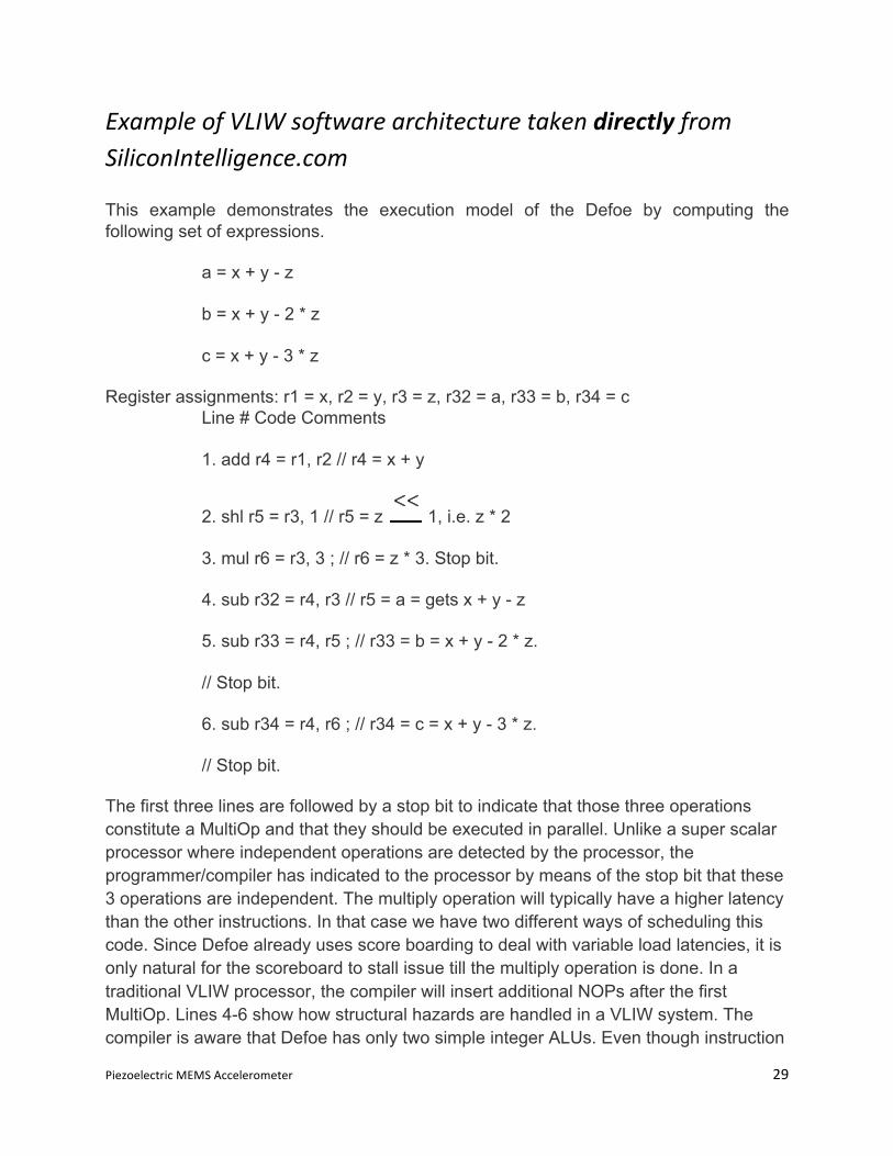
ExampleofVLIWsoftwarearchitecturetakendirectlyfromSiliconIntelligence.com
This example demonstrates the execution model of the Defoe by computing the following set of expressions.
a = x + y - z
b = x + y - 2 * z
c = x + y - 3 * z
Register assignments: r1 = x, r2 = y, r3 = z, r32 = a, r33 = b, r34 = c Line # Code Comments
1. add r4 = r1, r2 // r4 = x + y
2. shl r5 = r3, 1 // r5 = z 1, i.e. z * 2
3. mul r6 = r3, 3 ; // r6 = z * 3. Stop bit.
4. sub r32 = r4, r3 // r5 = a = gets x + y - z
5. sub r33 = r4, r5 ; // r33 = b = x + y - 2 * z.
// Stop bit.
6. sub r34 = r4, r6 ; // r34 = c = x + y - 3 * z.
// Stop bit.
The first three lines are followed by a stop bit to indicate that those three operations constitute a MultiOp and that they should be executed in parallel. Unlike a super scalar processor where independent operations are detected by the processor, the programmer/compiler has indicated to the processor by means of the stop bit that these 3 operations are independent. The multiply operation will typically have a higher latency than the other instructions. In that case we have two different ways of scheduling this code. Since Defoe already uses score boarding to deal with variable load latencies, it is only natural for the scoreboard to stall issue till the multiply operation is done. In a traditional VLIW processor, the compiler will insert additional NOPs after the first MultiOp. Lines 4-6 show how structural hazards are handled in a VLIW system. The compiler is aware that Defoe has only two simple integer ALUs. Even though instruction

PiezoelectricMEMSAccelerometer 30
6 is independent of instructions 4 and 5, because of the unavailability of a suitable function unit, instruction 6 is issued as a separate MultiOp, one cycle after its two predecessors. In a super scalar processor, this decision will be handled at run-time by the hardware.
Reference: B. K. Mathew, “Very Long Instruction Word Architectures (VLIW Processors and Trace Scheduling),” 2006, http://www.siliconintelligence.com/people/binu/coursework/686_vliw/node12.html