enhancement of power quality using self ... papers/ijmtarc-170620.pdfto improve power quality is the...
TRANSCRIPT

INTERNATIONAL JOURNAL OF MERGING TECHNOLOGY AND ADVANCED RESEARCH IN COMPUTING
IJMTARC – VOLUME – V – ISSUE - 18 – JUNE , 2017 ISSN: 2320-1363
1
ENHANCEMENT OF POWER QUALITY USING SELF SUPPORTED DVR
1. KALYADAPU RAJASHEKAR 2. RAMAVATH SHANKAR NAIK
1.Pg Scholar, Department of EEE, SLC's Institute of Engineering and Technology,Hyderabad.
2.Associate Professor& HOD, Department Of EEE, SLC's Institute of Engineering and Technology, Hyderabad
Abstract: In this project, different voltage injection schemes for dynamic voltage restorers (DVRs) are analyzed with particular
focus on a new method used to minimize the rating of the voltage source converter (VSC) used in DVR. One of the best solutions
to improve power quality is the dynamic voltage restorer (DVR). DVR is a kind of custom power devices that can inject
active/reactive power to the power grids. This can protect loads from disturbances such as sag and swell. Usually DVR installed
between sensitive loads feeder and source in distribution system. Its features include lower cost, smaller size, and its fast dynamic
response to the disturbance a new control technique is proposed to control the capacitor-supported DVR. The control of a DVR is
demonstrated with a reduced-rating VSC. The reference load voltage is estimated using the unit vectors. The synchronous
reference frame theory is used for the conversion of voltages from rotating vectors to the stationary frame. The compensation of
the voltage sag, swell, and harmonics is demonstrated using a reduced-rating DVR. This project presents the simulation of DVR
system using MATLAB/SIMULINK.
Keywords: Dynamic Voltage Restorer (DVR), Power Quality, Unit Vector, Voltage Harmonics, Voltage Sag, Voltage
Swell.
I. INTRODUCTION
Dynamic voltage restores (DVRs) are now becoming
more established in industry to reduce the impact of voltage
dips on sensitive loads. A voltage dip is commonly defined as
any low voltage drop event between 10% and 90% of the
nominal RMS voltage, lasting between 0.5 cycles and 1 min.
In comparison with interruptions, voltage dips affect a large
number of customers and for some cases may cause
extremely serious problems. Voltage dips are one of the most
occurring power quality problems. They occur more often
and cause severe problems and economical losses. There are
different ways to mitigate voltage dips, swells and
interruptions in transmission and distribution systems. At
present, a wide range of very flexible controllers which
capitalize on newly available power electronics components
are emerging for custom power applications. Among these,
the distribution static compensator and the dynamic voltage
restorer are the most effective devices; both of them based on
the voltage source converter (SVC) principle. Fig.1 shows a
typical DVR series connected topology. The DVR essentially
consists of a series inverter (VSI), inverter output filter and
an energy storage device connected to the DC link. The basic
operation principle of the DVR is to inject an appropriate
voltage in series with the supply through injection
transformer whenever voltage sag or voltage swell is
detected. In addition to voltage sags and swells
compensation, DVR can also perform other tasks such as
harmonic compensation and Power Factor correction.
Compared to the other Custom Power devices, the DVR
clearly provides the best economic solution for its size and
capabilities. This research introduced Dynamic Voltage
Restorer (DVR) and its voltage compensation methods. At
the end, simulation results using MATLAB were illustrated
and discussed.
Fig.1. DVR Series Connected Topology.
II. DYNAMIC VOLTAGE RESTORER (DVR)
Among the different power quality problems voltage sags,
swells and harmonics creates the losses and tripping at the
consumer side. In order to overcome the problems the
concept of custom power devices emerged into the


distributions system. One of the most efficient and effective
modern custom power devices is DVR. A DVR is a series
connected solid state device that injects the voltage into the
system to order to regulate the load terminal voltage. The
primary function is to boost up the load side voltage rapidly
during voltage sag or swell in order to avoid any disruption
on load side voltage. With various topologies and various
controlling schemes DVR is used to improve power quality
problems, other than that DVR having special features as line
voltage harmonic compensation, reduction of transients in
voltage and fault current limitations.
A. Components of DVR
There are five important components of DVR as shown in
Fig.2
Fig.2. Components of DVR.
1. Voltage source PWM Inverter: It is a power electronic
system consisting of switching devices like MOSFET (Metal
Oxide Semiconductor Field Effect Transistor), GTO (Gate
Turn-Off Thyristor), IGBT (Insulated Gate Bipolar
Transistors) and IGCT (Insulated Gate Commutated
Thyristors), which can generate sinusoidal voltage at any
required frequency, magnitude and phase angle. The VSC is
used to either completely replace the supply voltage or to the
inject the missing voltage which is the difference between the
nominal voltage and the actual voltage. Usually VSC is not
only used for mitigation of voltages but also for the power
quality issues like flickers and harmonics.
2. Injection Transformer: It is used to connect the DVR
circuit to the distribution system. Transformer transforms and
couples the injected voltages generated by the VSC to the
incoming supply voltage. Low voltage windings are
connected to the DVR circuit and High voltage windings are
connected to the distribution system at the Point of Common
Coupling (PCC). In this work three single-phase transformer
or three-phase transformer may be used.
3. Storage Unit: It supplies the required energy to the VSC
via DC link for the generation of injected voltage in case of
sags or swells.
4. DC charging Circuit: The DC charging circuit performs
the following tasks. Firstly, it charges the energy source after
the compensation of sag/swell event. And secondly, it
maintains the DC link voltage at the nominal value.
5. Filter: It is used to maintain the low level harmonic
content generated by the VSC to the acceptable level.
B. Operation of DVR
The schematic diagram of DVR is as shown in Fig.3.
Three phase source voltages Vsa, Vsb and Vsc are connected
to the three-phase critical load through series impedance Za,
Zb and Zc and an injection transformer in each phase.
Because of the power quality problems the source voltages
become terminal voltages as Vta, Vtb and Vtc. To get
undistorted and balanced load voltages VLa, VLb and VLc,
DVR injects compensating voltages VCa, VCb and VCc
through the injection transformer. DVR is used three leg
VSC with IGBTs along with a DC capacitor or a Battery
energy storage system. A ripple filter (Lr, Cr) is used to filter
out the switching ripple in the injected voltage by the VSC.
Fig.3. Operation of DVR.
The operation of DVR for the compensation of sag and
swell in the supply voltage is shown in figure 3 with the help
of the phasor diagrams. Before sag the load voltages is
indicated as VL (pre-sag) and current as Isa’ in case of both
sag and swell operation. After the sag event, the terminal
voltage (Vta) is gets lowered in magnitude and lags the pre-
sag voltage by some angle. When DVR injects compensating
voltage VCa to maintain the load voltage VL at the rated
magnitude VCa is splited into two components VCad and
VCaq. The voltage in-phase with the current VCad is
required to regulate the DC bus voltage and also to meet the
power losses in the VSC of the DVR and an injection
transformer. The voltage in quadrature with the current VCaq
is required to regulate the load voltage VL at constant
magnitude. During Swell event, the injected voltage VCa is
such that the load voltage lies on the locus of the circle as
shown Fig.4b.

Fig.4. Phasor Diagram, 4(a) Voltage Sag, 4(b) Voltage
Swell.
C. Voltage Injection Schemes
Depending upon the phase angle and magnitude
differences in the terminal voltage DVR injects the voltage to
maintain the balanced load voltages. Injection schemes
depend on several limiting factors such as DVR power rating,
load conditions and voltage sag type. Therefore the control
strategies to be applied depend upon the load characteristics.
There are four different methods of DVR voltage injection
schemes.
Scheme-1: Pre-Sag Compensation Method: It tracks the
supply voltage continuously and if it detects any disturbance
in that voltage it will inject the difference voltage between
the sag or voltage at the PCC and the ideal pre-fault
condition. In this way, the load voltage can be restored back
to the pre-fault condition. Compensation of voltage sags in
both phase angle and an amplitude sensitive load has to be
achieved by the pre-sag compensation method as shown in
Fig.5. In this method, the active power injected by the DVR
cannot be controlled and it is determined by external
conditions such as the type of faults and the loading
conditions.
Fig.5.Single phase vector diagram of Pre-Sag compensation
method.
Scheme-2: In-Phase Compensation Method: It is the most
straight forward method. In this method the injected voltage
is in-phase with the PCC voltage regardless of the load
current and pre-fault voltage. The phase angles of the pre-sag
and load voltage are different but the attention is placed on
maintaining a constant voltage magnitude on the load. One of
the advantages of this method is that the amplitude of DVR
injection voltage is minimum for certain voltage sag in
comparison with other schemes. In practical applications the
loads which are not sensitive to phase angle jumps are
applicable for this method. Fig.6 is single-phase vector
diagram.
Fig.6. Single phase vector diagram of In-Phase
compensation method
Scheme-3: In-Phase Advance Compensation Method: In
this compensation method the real power used by DVR is
minimized by decreasing the power angle between the sag
voltage and the load current. In the above two cases active
power is injected into the system by the DVR during
disturbances. Moreover, the active power supplied is limit to
the stored energy in the DC link and this part is most
expensive part in the system. The minimization of injected
energy is achieved by making the injection voltage phasor
perpendicular to the load current phasor. In this method the
values of load current and voltage are fixed in the system so
one can change only the phase of the sag voltage. This
method is suitable for limited sag ranges. As shown in Fig.7.
Fig.7. Single phase vector diagram of In-phase advance
compensation method.
Scheme-4: Minimum Energy Injection Method: Generally
voltage magnitudes between 90-110% of the nominal voltage
and phase angle variations between 5-10% of the normal
state will not disturb the operation characteristics of loads.
This compensation method will maintain the load voltage
within the tolerance area with small change of voltage
magnitudes as shown in Fig.8.
Fig.8. Single phase vector diagram of Minimum energy
compensation method.
III. SIMULATION CIRCUIT RESULTS
In order to show the performance of the DVR in voltage
sags and swells mitigation, a simple distribution network was
simulated using MATLAB (Fig.9) and its final results A
DVR was connected to the system through a series
transformer with a capability to insert a maximum voltage of
50% of the phase to ground system nominal voltage. In this
simulation the In-Phase Compensation (IPC) method was
used. The load considered in the study is a 5.5 MVA capacity
with 0.92 p.f, lagging. Voltage sags: A case of Three-phase
voltage sag was simulated and the results are shown in
Fig.10a
Fig.9. matlab/simulink diagram of proposed DVR system
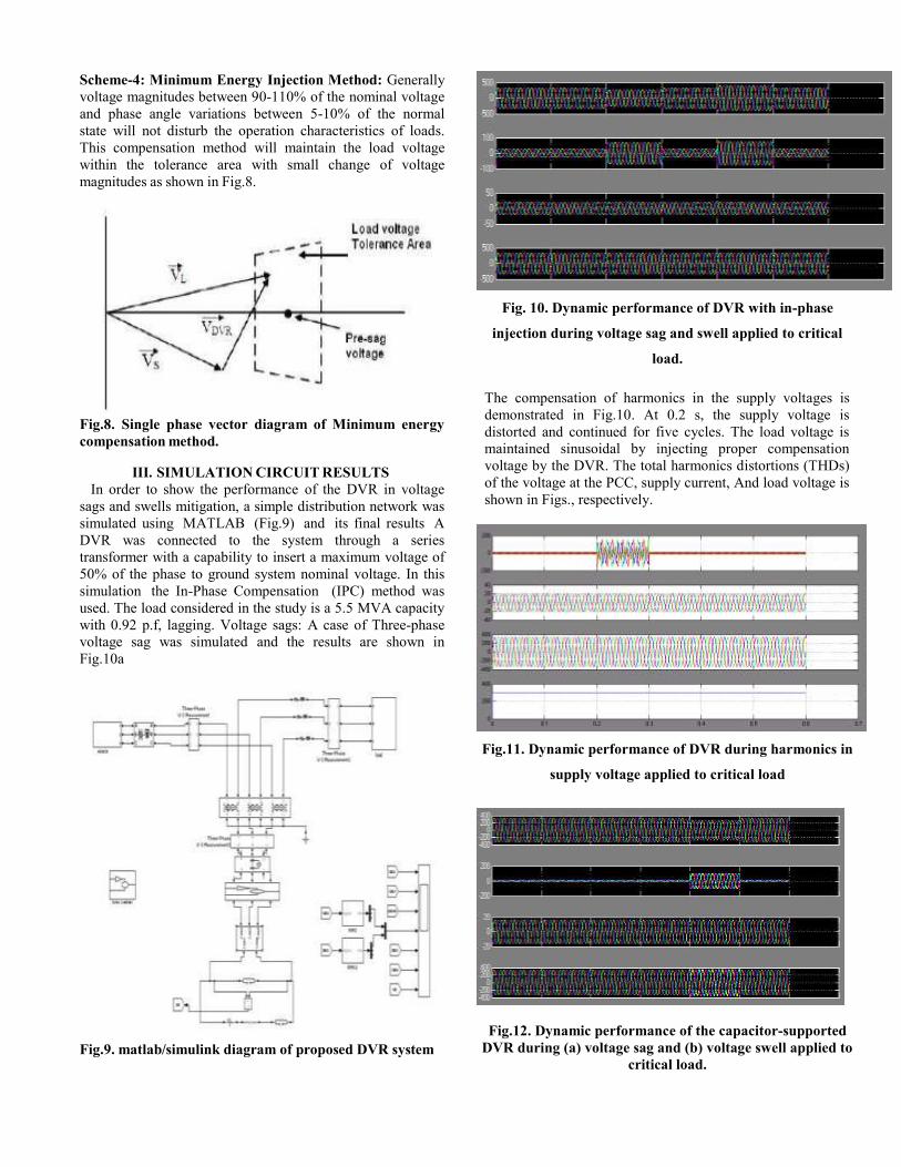
Fig. 10. Dynamic performance of DVR with in-phase
injection during voltage sag and swell applied to critical
load.
The compensation of harmonics in the supply voltages is
demonstrated in Fig.10. At 0.2 s, the supply voltage is
distorted and continued for five cycles. The load voltage is
maintained sinusoidal by injecting proper compensation
voltage by the DVR. The total harmonics distortions (THDs)
of the voltage at the PCC, supply current, And load voltage is
shown in Figs., respectively.
Fig.11. Dynamic performance of DVR during harmonics in
supply voltage applied to critical load
Fig.12. Dynamic performance of the capacitor-supported
DVR during (a) voltage sag and (b) voltage swell applied to
critical load.

IV.CONCLUSION
In this work the operation of DVR with different
voltage injections method are explained using SRF Theory.
For different types of power quality issues control schemes
varies. A new control technique is adopted to reduce the
rating of Voltage Source Converter. During in-phase voltage
injection scheme the rating of VSC is minimized, but affects
its cost on DC voltage source. Self supported DVR is widely
used as a consequence of modest cost with fewer components
for any type of Power quality problems. Simulation results
demonstrate about DVR with different control schemes and
successfully protect the sensitive loads without any power
quality issues.
V.REFERENCES
[1] Pychadathil Jayaprakash, Member, IEEE, Bhim
Singh, Fellow, IEEE, D. P. Kothari, Fellow, IEEE,
Ambrish Chandra, Senior Member, IEEE, and Kamal Al-
Haddad, Fellow, IEEE, ―Control of Reduced-Rating
Dynamic Voltage Restorer With a Battery Energy Storage
System‖, IEEE Transactions on Industry Applications,
Vol. 50, No. 2, March/April 2014.
[2] M. H. J. Bollen, Understanding Power Quality
Problems—Voltage Sags and Interruptions. New York, NY,
USA: IEEE Press, 2000.
[3] A. Ghosh and G. Ledwich, Power Quality Enhancement
Using Custom Power Devices. London, U.K.: Kluwer, 2002.
[4] M. H. J. Bollen and I. Gu, Signal Processing of Power
Quality Disturbances. Hoboken, NJ, USA: Wiley-IEEE
Press, 2006.
[5] R. C. Dugan, M. F. McGranaghan, and H. W. Beaty,
Electric Power Systems Quality, 2nd ed. New York, NY,
USA: McGraw-Hill, 2006.
[6] A. Moreno-Munoz, Power Quality: Mitigation
Technologies in a Distributed Environment. London, U.K.:
Springer-Verlag, 2007.
[7] K. R. Padiyar, FACTS Controllers in Transmission and
Distribution. New Delhi, India: New Age Int., 2007.
[8] IEEE Recommended Practices and Recommendations for
Harmonics Control in Electric Power Systems, IEEE Std.
519, 1992.
[9] V. B. Bhavraju and P. N. Enjeti, ―An active line
conditioner to balance voltages in a three phase system,‖
IEEE Trans. Ind. Appl., vol. 32, no. 2, pp. 287–292,
Mar./Apr. 1996.
[10] S. Middlekauff and E. Collins, ―System and customer
impact,‖ IEEE Trans. Power Del., vol. 13, no. 1, pp. 278–
282, Jan. 1998.
[11] M. Vilathgamuwa, R. Perera, S. Choi, and K. Tseng,
―Control of energy optimized dynamic voltage restorer,‖ in
Proc. IEEE IECON, 1999, vol. 2, pp. 873–878.
[12] J. G. Nielsen, F. Blaabjerg, and N.Mohan, ―Control
strategies for dynamic voltage restorer compensating voltage
sags with phase jump,‖ in Proc. IEEE APEC, 2001, vol. 2,
pp. 1267–1273.
AUTHOR’S PROFILE:
KALYADAPU
RAJASHEKAR received the B.Tech degree in
Electrical & Electronics Engineering from
Joginpallybasker engineering college in 2015 from
JNTU, Hyderabad, Telangana, India and He is
pursuing M.Tech in Electrical Power System(EPS) as
specialization in the Department of Electrical &
Electronics Engineering, SLC’s Institute of
Engineering and Technology, Affiliated to JNTU
Hyderabad, Telangana, India. His research area of
interests is Power system operation and control,
Power quality improvement.
E-mail id:[email protected]
Ramavath Shankar Naik received the B.Tech degree in Electrical Engineering from Vignan’s Engineering College, Vadlamudi, Guntur, India, in 2006. He Completed M.E in Electrical Engineering with Power system Automation as specialization in the Department of Electrical Engineering, Andhra University College of Engineering (Autonomous), Visakhapatnam, He is currently an Associate Professor with the Department of Electrical &Electronic Engineering at SLC College Jntu University, Hyderabad, Telangana, India. His area of interest lies in Power system operation and control, optimal operation of power systems, and FACTS. E-mail id: [email protected]