english - solar-bazaar.com · steca was quick to recognise the opportunities of a ... dormer cast...
TRANSCRIPT

www.steca.com
„PV Grid Connected – Power from the sun for everyday use.“
english
PV Grid Connected

Co
nte
nt
Co
nte
nt
�|
Steca Elektronik GmbH | 87700 Memmingen | Germany | Fon +49 (0) 8331 8558-0 | Fax +49 (0) 8331 8558-132 | www.steca.com
|�
Content
Commercial systems for agriculture and industry and ground-mounted installations
Steca – specialist in "difficult roofs"
CompanyResidential systems: single-family houses, apartment buildings, carports and garages
PV Grid Connected – Power from the sun ... 4
Residential systems 6Overview of devices 7
Commercial systems 8Overview of devices 9
Steca – specialist in "difficult roofs" 10Overview of devices 11
Yield analysis 128.2 % more profit ...
Steca Solsafe 14Overview of devices 15
Product information inverter systems 16
StecaGrid 300 and StecaGrid 500StecaGrid 300 and StecaGrid 500 20StecaGrid 300 Best in Test! 21StecaGrid ENS26 22StecaGrid ALD1 23DC circuit breaker 23
StecaGrid 1900, StecaGrid 2000+, StecaGrid 2010+StecaGrid 1900 24StecaGrid 2000+ 26StecaGrid 2010+ 28DC circuit breaker 30StecaGrid Connect PC network interface 31
StecaGrid 9000 3ph, StecaGrid 10 000 3phStecaGrid 9000 3ph 32StecaGrid 10 000 3ph 34Meteocontrol WEB‘log for remote monitoring 36StecaGrid Vision 37
Software for professional system dimensioning StecaGrid Configurator 3.0 38
Service informationfor StecaGrid inverter 39
Environmental protection in series 40
Steca product ranges 42
Room for notes 45
Symbols 47

Steca Helix 1100 dating to 1996
PV G
rid
Co
nn
ecte
d
PV G
rid
Co
nn
ecte
d
4|
Steca Elektronik GmbH | 87700 Memmingen | Germany | Fon +49 (0) 8331 8558-0 | Fax +49 (0) 8331 8558-132 | www.steca.com
|5
Residential systems
Commercial systems
Steca – specialist in "difficult roofs"
Product informationinverter systems
Software for professional system dimensioning
Service information
Steca was quick to recognise the opportunities of a boom in the making: The company has become syno-ny mous all over the world with vision, innovation, and initiative in the name of solar power. Steca is a recognised specialist in the development of high-performance systems which turn light into electricity before feeding it into the public grid.
30 years of experience
And not without reason: ever since the company was founded in 1976 – over �0 years ago, that is – Steca has developed inverter technologies and power elec-tronics for heavy-duty operating conditions.
Thus, when the German federal government initi-ated the 1,000 Roofs Programme in the early 1990s, which supported photovoltaic systems nationwide for the first time in Germany, it was easy for the company to make a significant contribution: the majority of the inverters installed at that time came from Steca.
The energy sources of the future are renewable.
In one hour, the amount of energy radiated to the earth by the sun exceeds the annual energy require-ment of the world population. Making use of this inexhaustible energy source for our everyday electri-city requirement is the great challenge of the present and the future.
The energy crises of the 197�s and a general grow-ing environmental awareness has also motivated politicians to push ahead with efforts to tap into the sun as an inexhaustible energy source and (as with-out financial incentives, it just won't work) to make this economically beneficial.
Power from the sun ...
... for everyday use.

Res
iden
tial
Sys
tem
s
Res
iden
tial
Sys
tem
s
A
F
C
BD
G
E
StecaGrid 300 and StecaGrid 500Grid inverter�00 W - �,600 W(page 20)
6|
Steca Elektronik GmbH | 87700 Memmingen | Germany | Fon +49 (0) 8331 8558-0 | Fax +49 (0) 8331 8558-132 | www.steca.com
|7
Overview of devices:
Solar power provides independence
Independence from the pricing arrangements of the large energy producers. Independence from energy policy in crisis countries, for instance in the Middle East. And last but not least: independence from the power outage risk of large electricity suppliers.
Key:
A Solar modulesB Grid inverterC Grid-feed electricity meterD House connection pointE Public electricity networkF Consumption electricity meterG Electrical load
It is now common knowledge that photovolta-ics help preserve the climate and the environment. However, there are additional, far more decisive ad-vantages which speak in favour of the installation of a PV system.
Photovoltaics are decentralised
Solar power is generated right where it is needed. This means: no energy losses and no costs for trans-mission and distribution.
Residential systemsfor single-family houses, apartment buildings, carports and garages.
Simply generate electricity yourself!
Residential systems: in this market segment, photo-voltaic systems are typically installed on single-family houses. But garages, carports and the roofs of apart-ment buildings are also suitable for electricity gener-ation. The electricity is distributed locally throughout the settlement via the low voltage grid.
Here, there is a need for solutions adapted to the individual situation. Optimal yield with easy care and handling are criteria which count for the operators.
StecaGrid 2010+Grid inverter�,000 W up to several 10,000 W(page 28)
not shown:
StecaGrid 2000+ (page 26)
StecaGrid 1900 (page 24)
StecaGrid 2010+StecaGrid 300 and

Co
mm
erci
al S
yste
ms
Co
mm
erci
al S
yste
ms
A
C
B
DE
StecaGrid 10000 3phGrid inverter 10,000 W up to several 100,000 W(page 34)
not shown:StecaGrid 9000 3ph(page 32)
Meteocontrol WEB’logfor remote monitoring(page 32)
StecaGrid Vision Display unit(page 37)
8|
Steca Elektronik GmbH | 87700 Memmingen | Germany | Fon +49 (0) 8331 8558-0 | Fax +49 (0) 8331 8558-132 | www.steca.com
|9
Overview of devices:
Key:
A Solar modulesB Grid inverterC Grid-feed electricity meterD House connection pointE Public electricity network
Commercial systemsfor agriculture and industry and ground-mounted installations.
Solar energy systems are not only ecologically worth-while and financially profitable – thanks to the feed-in tariffs which are legally guaranteed in numerous countries, they are one of the most secure capital investments worldwide: thus, an ever-increasing number of systems are being realised by commercial investors and investment funds.
Your yield always in view
Systems in this segment are installed on commercial buildings, agricultural buildings, or on the ground.
In such cases, however, the system operator is often not the owner of the roof or surface. This in turn calls for professional remote system monitoring. In the event of a fault, an automatic alarm must imme-diately notify the system operator and possibly the installer as well.
First choice for thin-film modules
The occurrence of discharge current in a PV system is unavoidable. In the case of thin-film modules, this can lead to long-term damage and efficiency losses.
The solution to this problem is an inverter with an in-tegrated transformer: StecaGrid �000+ with in-built transformer offers security at 95 % efficiency!
StecaGrid 2010+Grid inverter �,000 W up to several 10,000 W(page 28)
not shown:
StecaGrid 2000+ (page 26)
StecaGrid 1900 (page 24)
StecaGrid 10000 3ph StecaGrid Vision

Spec
iali
st i
n D
iffi
cult
Ro
ofs
Spec
iali
st i
n D
iffi
cult
Ro
ofs
A
F
C
BD
G
E
10|
Steca Elektronik GmbH | 87700 Memmingen | Germany | Fon +49 (0) 8331 8558-0 | Fax +49 (0) 8331 8558-132 | www.steca.com
|11
Overview of devices:
Shadows waste money
As the weakest solar cell determines the total out-put of a whole module, even the shadow of a roof antenna can reduce the yield of a PV system by up to �0 percent!
Thus, before installation, it is important to ascertain what objects in the system's surroundings can cause shading and to dimension the system accordingly.
As a specialist in situations of this kind, Steca devel-ops individual solutions.
Key:
A Solar modulesB Grid inverterC Grid-feed electricity meterD House connection pointE Public electricity networkF Consumption electricity meterG Electrical load
What is the point of having the largest, south-facing, optimally inclined �0° roof surface, if a neighbouring building, a tree, a street lamp, or even the roof's own chimney casts its shadow on the new solar energy system? That's like driving with the handbrake on!
Specialist in difficult roofsSystems for shading and differently aligned roof surfaces.
StecaGrid 300 and StecaGrid 500Grid inverter �00 W - �,600 W(page 20)
StecaGrid 2010+Grid inverter �,000 W up to several 10,000 W(page 28)
not shown:
StecaGrid 2000+ (page 26)
StecaGrid 1900 (page 24)
StecaGrid 2010+StecaGrid 300 and
Yie
ld A
nal
ysis
Yie
ld A
nal
ysis
1�|
Steca Elektronik GmbH | 87700 Memmingen | Germany | Fon +49 (0) 8331 8558-0 | Fax +49 (0) 8331 8558-132 | www.steca.com
|1�
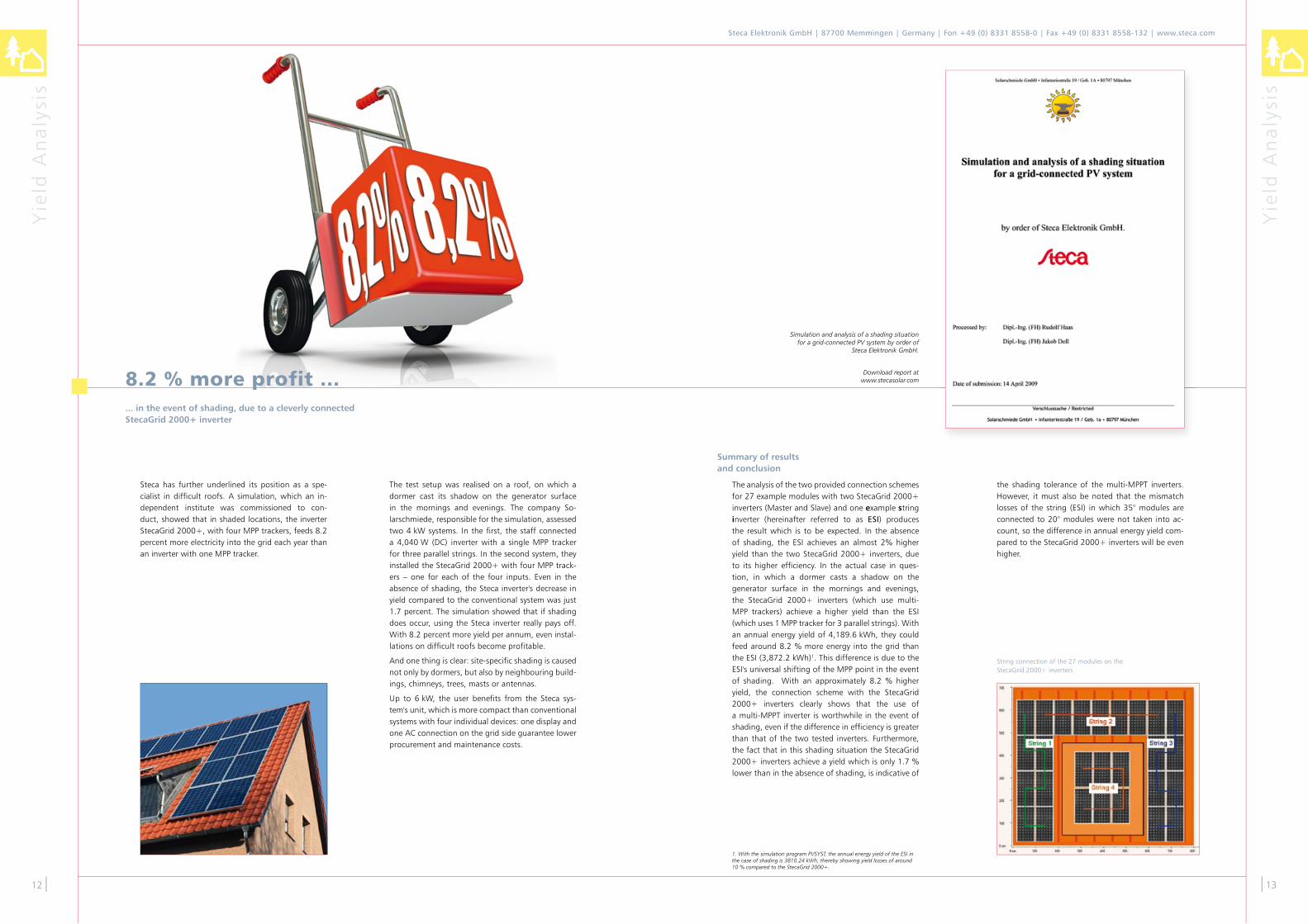
Steca has further underlined its position as a spe-cialist in difficult roofs. A simulation, which an in-dependent institute was commissioned to con-duct, showed that in shaded locations, the inverter StecaGrid �000+, with four MPP trackers, feeds 8.� percent more electricity into the grid each year than an inverter with one MPP tracker.
The test setup was realised on a roof, on which a dormer cast its shadow on the generator surface in the mornings and evenings. The company So-larschmiede, responsible for the simulation, assessed two 4 kW systems. In the first, the staff connected a 4,040 W (DC) inverter with a single MPP tracker for three parallel strings. In the second system, they installed the StecaGrid �000+ with four MPP track-ers – one for each of the four inputs. Even in the absence of shading, the Steca inverter's decrease in yield compared to the conventional system was just 1.7 percent. The simulation showed that if shading does occur, using the Steca inverter really pays off. With 8.� percent more yield per annum, even instal-lations on difficult roofs become profitable.
And one thing is clear: site-specific shading is caused not only by dormers, but also by neighbouring build-ings, chimneys, trees, masts or antennas.
Up to 6 kW, the user benefits from the Steca sys-tem's unit, which is more compact than conventional systems with four individual devices: one display and one AC connection on the grid side guarantee lower procurement and maintenance costs.
8.2 % more profit ...... in the event of shading, due to a cleverly connected StecaGrid 2000+ inverter
Simulation and analysis of a shading situation for a grid-connected PV system by order of
Steca Elektronik GmbH.
Download report at www.stecasolar.com
String connection of the �7 modules on the StecaGrid �000+ inverters
Summary of results and conclusion
The analysis of the two provided connection schemes for �7 example modules with two StecaGrid �000+ inverters (Master and Slave) and one example string inverter (hereinafter referred to as ESI) produces the result which is to be expected. In the absence of shading, the ESI achieves an almost �% higher yield than the two StecaGrid �000+ inverters, due to its higher efficiency. In the actual case in ques-tion, in which a dormer casts a shadow on the generator surface in the mornings and evenings, the StecaGrid �000+ inverters (which use multi-MPP trackers) achieve a higher yield than the ESI (which uses 1 MPP tracker for � parallel strings). With an annual energy yield of 4,189.6 kWh, they could feed around 8.� % more energy into the grid than the ESI (�,87�.� kWh)1. This difference is due to the ESI's universal shifting of the MPP point in the event of shading. With an approximately 8.� % higher yield, the connection scheme with the StecaGrid �000+ inverters clearly shows that the use of a multi-MPPT inverter is worthwhile in the event of shading, even if the difference in efficiency is greater than that of the two tested inverters. Furthermore, the fact that in this shading situation the StecaGrid �000+ inverters achieve a yield which is only 1.7 % lower than in the absence of shading, is indicative of
the shading tolerance of the multi-MPPT inverters. However, it must also be noted that the mismatch losses of the string (ESI) in which �5° modules are connected to �0° modules were not taken into ac-count, so the difference in annual energy yield com-pared to the StecaGrid �000+ inverters will be even higher.
1. With the simulation program PVSYST, the annual energy yield of the ESI in the case of shading is 3810.24 kWh, thereby showing yield losses of around 10 % compared to the StecaGrid 2000+.

Sols
afe
Tech
no
log
y
Sols
afe
Tech
no
log
y
AC
AC
AC
DC
DC
A
D
C
B
EF
G
H
Steca CompactSine wave inverter1,600 W - 4,000 W(Steca PV Off Grid)
Steca Compact ARM-01Relay module for Steca sine wave inverter
StecaGrid 10000 3ph Grid inverter10,000 W up to several 100,000 W(page 34)
not shown:
StecaGrid 9000 3ph(page 32)
StecaGrid 10000 3ph Steca Xtender XTHSine wave inverter�,000 W - 7�,000 W(Steca PV Off Grid)
Steca Xtender XTMSine wave inverter1,500 W - �6,000 W(Steca PV Off Grid)
Steca Xtender XTM
Solasafe S-Box Anti-blackout system for Steca sine wave inverter
Steca XPC Sine wave inverter1,400 W - �,�00 W(Steca PV Off Grid)
Steca XPC
StecaGrid 2010+Grid inverter�,000 W up to several 10,000 W(page 28)
not shown:
StecaGrid 2000+ (page 26)StecaGrid 1900 (page 24)
Steca HPCSine wave inverter�,800 W - 8,000 W(Steca PV Off Grid)
StecaGrid 300 and StecaGrid 500Grid inverter�00 W - �,600 W(page 20)
StecaGrid 300 and
14|
Steca Elektronik GmbH | 87700 Memmingen | Germany | Fon +49 (0) 8331 8558-0 | Fax +49 (0) 8331 8558-132 | www.steca.com
|15
Why choose Steca Solsafe? It allows great system flexibility. The grid inverter is designed according to the PV generator, and the sine wave inverter according to the desired emergency power supply.
The PV system’s output and operating voltage can be freely selected, and do not depend on the size and battery voltage of the emergency power supply.It should be noted, however, that the AC output of the grid inverter may never be greater than the rated output of the sine wave inverter.
The PV voltage of the grid inverter does not depend on the battery voltage.
Existing grid-connected solar power systems can be fitted with Steca Solsafe without alterations of any kind.
The available PV capacity is added to that of the sine wave inverter in the event of a power outage, or the solar power is stored in the battery.
Overview of devices:
Large-scale power supply failures are beco-ming increasingly common. With emergency systems such as generators or uninterruptib-le power supplies (UPS), the power supply can be assured.
Yet, in the event of a power outage, the grid-con-nected PV system also stops working. This means that although power may be available, it cannot be used. The Solsafe system offers a simple, efficient and cost-effective solution to this problem.
Installing one of our combined inverters Steca XPC, Steca Compact, Steca HPC, Steca Xtender XTM or Steca Xtender XTH with the supplementary ARM-01 relay module and a battery system turns any grid-connected PV system into an emergency power sup-ply in the event of a power outage. If the public grid is available, the electrical output generated by the solar modules is fed directly into the grid by the grid inverter (B) and the grid-feed electricity meter (D). In parallel to this, the unsupplied loads (H) receive power directly from the grid, via the consumption electricity meter (E). The batteries are kept fully char-ged from the public grid via the hybrid system inver-ter (F), and, if necessary, they are recharged. Further-more, the supplied loads (G) receive power from the public grid during transfer mode.
If there is a grid outage, the hybrid system inver-ter automatically switches mode to operate as a sine wave inverter, and continues to feed power to the supplied loads (G) without any interruption. Because the grid inverter can no longer supply power to the grid, its output is channelled directly to the supplied loads (G) by the ARM-01 relay module (C). In this way, the loads can receive power directly from the grid inverter of the solar modules. At the same ti-me, the battery can be recharged with the available solar energy, which increases the length of time for which the supplied loads can receive power during the night.
With this set-up, the capacity of the battery can be kept small, allowing for an optimal design of system costs.
The Solsafe system is fully automatic, and can be in-tegrated into any new or existing PV system.
Solsafe ensures the power supply, and furthermore al-lows the solar energy to be fully utilised.
Key:
A Solar modulesB Grid inverterC Relay module ARM-01D Grid-feed electricity meterE Consumption electricity meterF Sine wave inverter G Supplied loadsH Unsupplied loads
Steca SolsafeBlackout - and yet it stays light!

Pro
du
ct I
nfo
rmat
ion
Pro
du
ct I
nfo
rmat
ion
16|
Steca Elektronik GmbH | 87700 Memmingen | Germany | Fon +49 (0) 8331 8558-0 | Fax +49 (0) 8331 8558-132 | www.steca.com
|17
Together with their range of accessories, the Steca- Grid inverters represent an innovative family of in-verter solutions for grid-connected solar power sys-tems.
The modular concept offers you over 100 different possibilities for designing an inverter system tailored to your individual needs. With MiniString, DualSt-ring, or UniString inverters, Steca always offers you the optimal inverter for your system.
Maximum flexibility for maximum results
To achieve this, Steca has developed modular com-ponents which offer made-to-measure solutions for the widest range of household sizes and demands. Whether being used in a small solar power system for a single-family house or an elaborate combined solution for an industrial complex, Steca grid-feed inverters all have one thing in common: They offer the highest performance along with maximum flexi-bility and ease of use.
Every roof is unique ...
This calls for individual solutions.
... modular and flexible.The StecaGrid �00 and StecaGrid 500 inverters are perfectly suited to smaller solar power systems start-ing at �00 W. Thanks to the modularity, this is the inverter of choice in systems with differently aligned or partially shaded roofs, and on smaller surfaces (garage roofs, summer houses).
The inverters StecaGrid �00 and StecaGrid 500 were developed to make the use of solar energy as simple as possible. They are simple to install, easy to ex-pand, and can be optimally adjusted to suit the local irradiation conditions.
StecaGrid 300/500
Pro
du
ct I
nfo
rmat
ion
Pro
du
ct I
nfo
rmat
ion
18|
Steca Elektronik GmbH | 87700 Memmingen | Germany | Fon +49 (0) 8331 8558-0 | Fax +49 (0) 8331 8558-132 | www.steca.com
|19
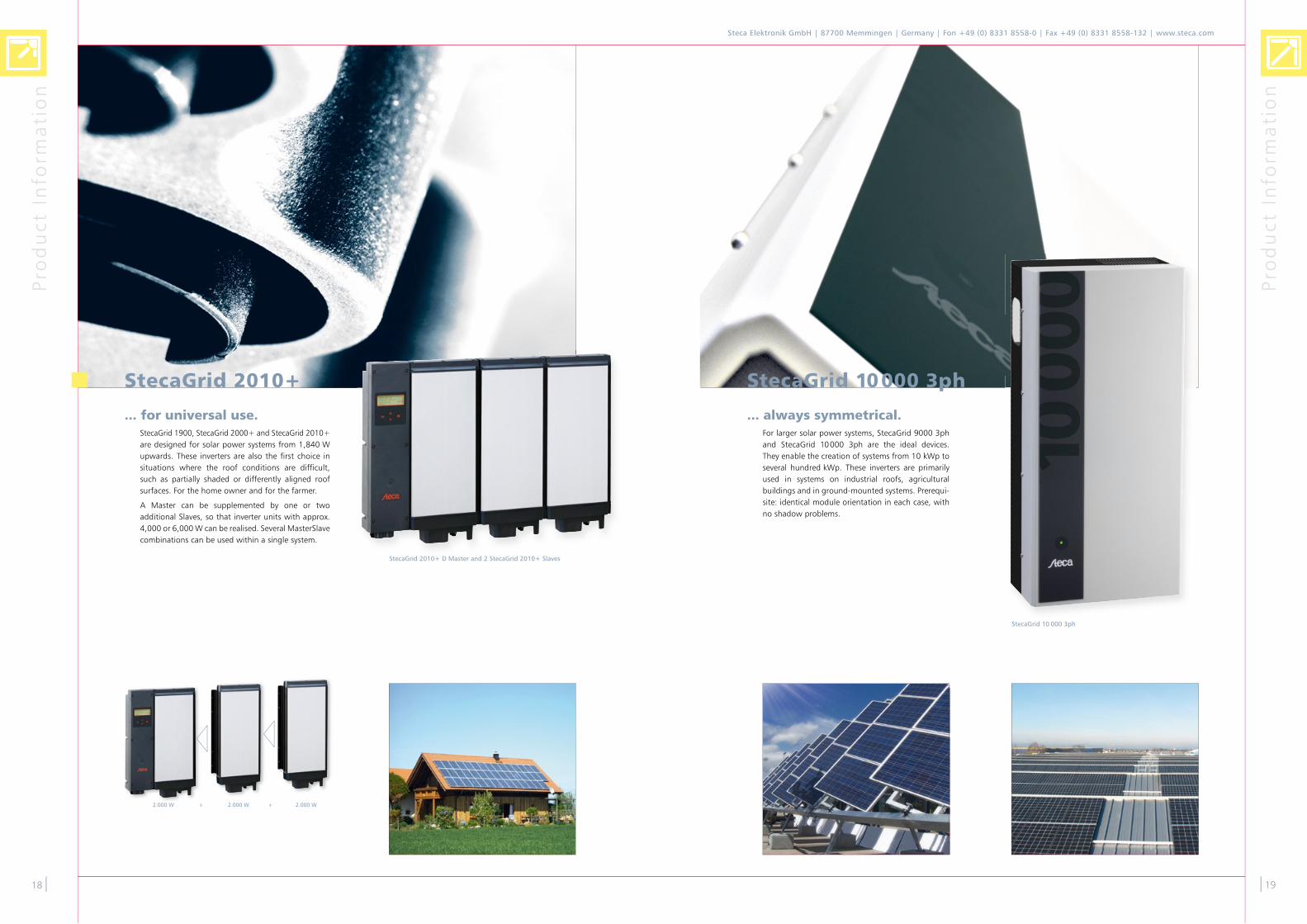
StecaGrid 10 000 3ph
2.000 W + 2.000 W + 2.000 W
... always symmetrical. For larger solar power systems, StecaGrid 9000 �ph and StecaGrid 10000 �ph are the ideal devices. They enable the creation of systems from 10 kWp to several hundred kWp. These inverters are primarily used in systems on industrial roofs, agricultural buildings and in ground-mounted systems. Prerequi-site: identical module orientation in each case, with no shadow problems.
... for universal use.StecaGrid 1900, StecaGrid �000+ and StecaGrid �010+ are designed for solar power systems from 1,840 W upwards. These inverters are also the first choice in situations where the roof conditions are difficult, such as partially shaded or differently aligned roof surfaces. For the home owner and for the farmer.
A Master can be supplemented by one or two additional Slaves, so that inverter units with approx. 4,000 or 6,000 W can be realised. Several Master Slave com binations can be used within a single system.
StecaGrid 10000 3phStecaGrid 2010+
StecaGrid 2010+ D Master and 2 StecaGrid 2010+ Slaves

71 176
243
Stec
aGri
d �
00
an
d 5
00
Stec
aGri
d �
00
an
d 5
00
�0|
Steca Elektronik GmbH | 87700 Memmingen | Germany | Fon +49 (0) 8331 8558-0 | Fax +49 (0) 8331 8558-132 | www.steca.com
|�1
StecaGrid 300 and StecaGrid 500The MiniString inverter series comprises the StecaGrid �00 and StecaGrid 500 inverters, with rated outputs of �00 W and 500 W, respectively.
StecaGrid �00 and StecaGrid 500 are built in a modular man-ner, and simple to install. With distribution over three phas-es, the system can at any time be expanded as desired, and thus flexibly adapts to your solar power system investment. StecaGrid �00 and StecaGrid 500 have an independent MPP tracker and achieve a very high efficiency of up to 95.8 %.
Product featuresFlexible and expandable
High efficiency
MiniString concept
Low weight
Simple installation
Wall-mounting with top-hat rail
Electronic protection functionsIntegrated temperature monitoring with output derating
DisplaysMulti-coloured LED shows operating status
OptionsUnited Kingdom variants as per G8� available
StecaGrid 300 StecaGrid 500
DC input side (PV-generator)
Maximum start voltage 100 V 170 V
Maximum input voltage 1�5 V ��0 V
Minimum input voltage 45 V 75 V
Minimum input voltage for rated output
64 V 106 V
MPP voltage 45 V ... 100 V 75 V ... 170 V
Maximum input current 5 A
Maximum input power ��0 W 5�0 W
Maximum recommended PV power
�75 Wp 6�5 Wp
Derating / limiting automatic when- input power is higher- the device is not cooled sufficiently- input currents > 5 A(higher currents are limited by the equipment and therefore will not damage the inverter)
AC output side (Grid connection)
Grid voltage �07 V … �5� V [other values are possible]
Rated grid voltage ��0 V
Maximum output current 1.5 A �.5 A
Maximum output power �00 W 500 W
Rated power �00 W 500 W
Rated frequency 50 Hz
Frequency 48 Hz … 5� Hz [other values are possible]
Night-time power loss < 0.1 W
Feeding phases single-phase
Power factor > 0.95
Distortion factor < 6 % (max. power) < 5 % (max. power)
Characterisation of the operating performance
Maximum efficiency 94.8 % 95.8 %
European efficiency 9�.4 % 94.5 %
MPP efficiency 99 %
Power derating at full power from 40 °C
Switch-on power � W
Standby power 0 W
StecaGrid 300 StecaGrid 500
Safety
Isolation principle no galvanic isolation, transformerless
Grid monitoring optional via StecaGrid ENS �6
Operating conditions
Area of application indoor rooms, with or without air conditioning
Ambient temperature -�0 °C ... +45 °C
Relative humidity 0 % ... 95 %
Noise emission < �� dBA
Fitting and construction
Degree of protection IP �0
DC Input side connection MultiContact MC �, MC 4
AC output side connection Wieland Electric GST 18i�V plug
Dimensions (X x Y x Z) 176 x �4� x 71 mm
Weight 1.4 kg
DC circuit breaker no
Cooling principle natural convection
Test certificate CE mark, DK 5940
[a reas of appl i cat ion]
StecaGrid 300 Best in Test !Most efficient inverter
The StecaGrid �00 inverter was the top performer in a test of small grid-connected inverters and solar modules conducted by the renowned Paul Scherrer Institut in Switzerland. The testers determined that the test winner from the Memmin-gen-based Steca solar electronic company was the most ef-ficient in its class. According to study data, the efficiency of the StecaGrid �00 rises relatively quickly and remains at a constantly high level. It won the top spot among the tested devices with 9�.5 per cent.
BEST IN TEST
The StecaGrid 500 was also awarded high marks in the test. This was confirmed in a report by the Swiss trade journal „Erneuerbare Energien“ („Renewable Energy“) on the effi-ciency of solar power systems. In the December �007 issue the journal came to the conclusion that „according to our measurements the StecaGrid inverters were clearly the best performers.“ The test report of the Paul Scherrer Institut can be downloaded at http://tpv-pv.web.psi.ch/grid_pv.pdf The StecaGrid �00 and 500 have not just proved to be particular-ly efficient; they also stand out with their flexibility. The mo-dularity of MiniString inverters makes them ideal for garages, carports, terraced and single-family houses. Moreover, due to the short strings and numerous MPP trackers, they are very well suited for small-section or partially shaded roofs.

Stec
aGri
d �
00
an
d 5
00
Stec
aGri
d �
00
an
d 5
00
��|
Steca Elektronik GmbH | 87700 Memmingen | Germany | Fon +49 (0) 8331 8558-0 | Fax +49 (0) 8331 8558-132 | www.steca.com
|��
DC circuit breaker for StecaGrid 300 and StecaGrid 500
250 V DC, 6 A DC, 6-pole
One DC circuit breaker can be used for one to three inverters. If the inputs are single-phased, up to six inverters can be con-nected via one DC circuit breaker.
CertificatesCompliant with DIN VDE 0100-71�
DC circuit breaker for StecaGrid 300 and StecaGrid 500
DC input side (PV-generator)
Maximum input voltage �50 V
Maximum input current 6 A per contact
Operating conditions
Area of application indoor rooms, with or without air conditioning, outdoors with or
without protection
Ambient temperature -40 °C … +60 °C
Relative humidity 0 % ... 95 %
Fitting and construction
Degree of protection IP 65
Terminal (fine / single wire) 10 mm� / 16 mm�
Dimensions (X x Y x Z) 1�5 x �00 x 1�� mm
Weight 1.� kg
Test certificate CE mark Wiring information for the DC circuit breaker can be
found on our website (www.steca.com).
[areas of appl i cat ion] [areas of appl i cat ion]
StecaGrid ENS26
AC output side (Grid connection)
Rated grid voltage ��0 V
Rated frequency 50 Hz
Characterisation of the operating performance
Switched power < 5,750 W
Rated current of power feeder < �5 A
Own consumption 1.5 W
Safety
Grid monitoring compliant with DIN VDE 01�6-1-1
Overvoltage (fast shutdown) > �00 V (response time 0.0� s)
Overvoltage > �64 V (response time 0.� s)
Overvoltage ��0 V +10 % over 10 min.
Undervoltage (fast shutdown) < 1�0 V (response time 0.0� s)
Undervoltage < 185 V (response time 0.� s)
Frequency deviation +0.� Hz / -�.5 Hz (response time 0.� s)
Rate of Change of Frequency (RoCoF) > 1 Hz / s
Impedance jump detection > 0.5 Ohm (response time 0.5 s)
Operating conditions
Ambient temperature -�0 °C … +40 °C
Relative humidity 10 % … 90 %, non-condensating
Fitting and construction
Dimensions (X x Y x Z) 146 x 111 x 80 mm
Test certificate certificate of compliance, CE mark
StecaGrid ALD1
AC output side (Grid connection)
Rated grid voltage ��0 V (-�0 % / +15 %)
Rated frequency 50 Hz
Rated current 5 A
Measurement current �� A
Starting current �0 mA
Minimum current 0.�5 A
Power consumption active 0.4 W
Characterisation of the operating performance
Accuracy class 1 (1 %) as per IEC 6� 05�-�1 or B in accordance with EN 50 470-� (devices in accordance with MID)
Measurement direct
Safety
Protection class II
Insulation characteristics 4 kV / 50 Hz test in accordance with VDE 04�56 kV 1.� / 50 µs surge voltage in accordance with
IEC �55-4
Operating conditions
Ambient temperature -10 °C … +55 °C
Storage temperature -�0 °C … +85 °C
Relative humidity 95 % at �5 °C … 40 °C, non-condensating
Fitting and construction
Terminal (fine / single wire)
primary circuit: max. 6 mm�
impulse output: max. �,5 mm�
Dimensions (X x Y x Z) 17.5 x 89.� x 6�.4 mm
S0 output optocoupler max. �0 V / �0 mA and min. 5 V, impedance 100 Ω, impulse range 50 ms,
transmission distance max.1,000 m (at �0 V / �0 mA)
Pulses per kWh �,000 (LC display), 1,000 (S0 output)
Test certificate CE mark
StecaGrid ALD1Digital energy meter
Product featuresWall-mounting with top-hat rail
DisplaysLCD display with backlight, digits 5 mm high
StecaGrid ENS26The automatic, one-phase isolation unit is an automatic swit-ching unit used to connect decentralised power generators safely to the public electricity supply.
The StecaGrid ENS�6 isolation unit has been conceived as an independent unit for monitoring one-phase power feeding systems. It prevents uncontrolled island effects following failure or shutdown of the public electricity supply.
The StecaGrid ENS�6 complies with DIN VDE 01�6-1-1 and is approved as a substitute for manual isolation devices up to a 5.75 kW feeding power.
The StecaGrid ENS�6 automatic isolation unit continually monitors
– overvoltage and undervoltage
– frequency deviation
– impedance jumps
in the public electricity supply.
In the event of faults in the mains supply, the StecaGrid ENS�6 interrupts the feeding of electricity in the mains to prevent island effects.
The disconnection of L and N is accomplished by two relays. Each relay is specified for a switching current of �5 A.
The contact distance within the relay is in accordance to the overvoltage category � at �50 V AC.
The safety functions are executed in a dual channel system, whereby each channel monitors the proper function of the other channel. In case of a failure the channels disconnect independently from each other.
The channels monitor each other mutually (refer to the error protection in accordance with DIN VDE 01�6) to increase er-ror protection.

Stec
aGri
d 1
90
0 /
�0
00
+ /
�0
10
+
Stec
aGri
d 1
90
0 /
�0
00
+ /
�0
10
+
StecaGrid 1900 SlaveStecaGrid 1900 D Master
127
224
226
535
StecaGrid 1900 Slave
351
542
535
127
StecaGrid 1900 D Master
�4|
Steca Elektronik GmbH | 87700 Memmingen | Germany | Fon +49 (0) 8331 8558-0 | Fax +49 (0) 8331 8558-132 | www.steca.com
|�5
StecaGrid 19001,840 W up to several 10,000 W
The DualString product range consists of masters and slaves. Like the slaves, the master includes an inverter, but it also pro-vides additional functions: a four-line display, a data logger for storing the yield values, country-specific grid moni toring of the alternating current output, and optional use of an inter-face card.
Flexible system design
The StecaGrid 1900 uses the DualString concept. This means that every inverter (master or slave) has two inputs, with each input having its own MPP tracker. One module string can be connected to each input. If required, the inputs can also be connected in parallel.
The advantage of such a system is the low sensitivity to ne-gative influences such as (e.g.) partial shadowing, functional faults, or the dropout of a string. The use of several decen-tralised master-slave combinations reduces the cost of DC cabling, and minimises electrical losses.
Galvanic isolation
DualString inverters from Steca are equipped with a high-fre-quency transformer, and are thus galvanically isolated. This enables unrestricted use of thin-film modules. Nevertheless, high efficiency of up to 95 % is achieved.
Diverse application situations
StecaGrid inverters offer constant high-power capability over a wide range of ambient temperatures. This is supported by maintenance-free, natural convection via the large-dimension cooling fins. Since no fans are used, the inverters work in virtual silence. Thanks to the high degree of protection, Steca-Grid DualString inverters are also suitable for outdoor instal-lation.
StecaGrid 1900 D Master can be combined with StecaGrid �000+ Slave and StecaGrid �010+ Slave.
Product featuresTwo Maximum Power Point Trackers (MPP tracker) per device
Flexible and expandable
High efficiency
DualString concept
Low weight
Simple installation
MasterSlave concept
Suitable for outdoor installation
Fanless and maintenance-free
Integrated data logger
Wall-mounting with steel wall bracket for very easy installation
Electronic protection functionsIntegrated temperature monitoring with output derating
DisplaysText LCD display
for current output, energy yields, operating parameters, date, time, service information
Multi-coloured LED shows operating states
OperationMultilingual menu navigation
Four cursor buttons for menu selection
—
StecaGrid 1900 D Master StecaGrid 1900 Slave
DC input side (PV-generator)
Maximum start voltage 410 V
Maximum input voltage 450 V (higher voltages can damage the device)
Minimum input voltage 80 V
Minimum input voltage for rated output 1�� V
MPP voltage 80 V … 400 V
Maximum input current � x 8 A [current limited by inverter] or 1 x 16 A [parallel inputs]
Maximum input power 1,000 W [per input] or �,000 W [� parallel inputs]
Maximum recommended PV power �,�00 Wp
Derating / limiting automatic when - input power is higher (> 1,000 W / input)- the device is not cooled sufficiently- input currents > � x 8 A or 1 x 16 A (parallel inputs))(higher currents are limited by the equipment and therefore will not damage the inverter)
AC output side (Grid connection)
Grid voltage 190 V ... �65 V [depending on regional settings]
Rated grid voltage ��0 V
Maximum output current 10 A
Maximum output power 1,840 W
Rated power 1,840 W
Rated frequency 50 Hz
Frequency 47.5 Hz ... 5� Hz [depending on regional settings]
Night-time power loss 1.� W 0 W
Feeding phases single-phase
Power factor > 0.95
Distortion factor < 5 % (max. power)
Characterisation of the operating performance
Maximum efficiency 95 %
European efficiency 9�.� % 9�.5 %
MPP efficiency > 99 %
Power derating at full power from 45 °C (Tamb)
Switch-on power �0 W
Standby power � W
Safety
Isolation principle HF-transformer with galvanic separation and amplified isolation
Grid monitoring MSD, compliant with DIN VDE 01�6-1-1 via master
Selectable parameter settings Greece, France, Spain, Portugal, Italy, Great Britain via master
Operating conditions
Area of application indoor rooms with or without air conditioning, outdoors with or without protection
Ambient temperature -�5 °C ... +60 °C
Relative humidity 0 % ... 95 %
Noise emission < �� dBA
Fitting and construction
Degree of protection IP 65
DC Input side connection MultiContact MC 4
AC output side connection WAGO �.5 mm� ... 6 mm² via master
Dimensions (X x Y x Z) �51 x 54� x 140* mm ��6 x 5�5 x 140* mm
Weight approx. 11 kg approx. 9 kg
Communication interface optional StecaGrid Connect with Ethernet interface
DC circuit breaker no
Cooling principle natural convection
Test certificate certificate of compliance, CE mark
*incl. mounting plate
[a reas of appl i cat ion]
1,840 W + 1,840 W + 1,840 W StecaGrid 1900 D Master and 2 StecaGrid 1900 Slaves
StecaGrid 1900: Master-Slave combination

Stec
aGri
d 1
90
0 /
�0
00
+ /
�0
10
+
Stec
aGri
d 1
90
0 /
�0
00
+ /
�0
10
+
StecaGrid 2000+ SlaveStecaGrid 2000+ Master
127
224
226
535
StecaGrid 2000+ Slave
351
542
535
127
StecaGrid 2000+ Master
�6|
Steca Elektronik GmbH | 87700 Memmingen | Germany | Fon +49 (0) 8331 8558-0 | Fax +49 (0) 8331 8558-132 | www.steca.com
|�7
StecaGrid 2000+2,000 W up to several 10,000 W
The DualString product range consists of masters and slaves. Like the slaves, the master includes an inverter, but it also pro-vides additional functions: a four-line display, a data logger for storing the yield values, country-specific grid monitoring of the alternating current output, and optional use of an in-terface card.
Flexible system design
The StecaGrid �000+ uses the DualString concept. This means that every inverter (master or slave) has two inputs, with each input having its own MPP tracker. One module st-ring can be connected to each input. If required, the inputs can also be connected in parallel.
The advantage of such a system is the low sensitivity to ne-gative influences such as (e.g.) partial shadowing, functional faults, or the dropout of a string. The use of several decen-tralised master-slave combinations reduces the cost of DC cabling, and minimises electrical losses.
Galvanic isolation
DualString inverters from Steca are equipped with a high-fre-quency transformer, and are thus galvanically isolated. This enables unrestricted use of thin-film modules. Nevertheless, high efficiency of up to 95 % is achieved.
Diverse application situations
StecaGrid inverters offer constant high-power capability over a wide range of ambient temperatures. This is supported by maintenance-free, natural convection via the large-dimensi-on cooling fins. Since no fans are used, the inverters work in virtual silence. Thanks to the high degree of protection, StecaGrid DualString inverters are also suitable for outdoor installation.
StecaGrid �000+ D Master and StecaGrid �000+ Master can be combined with StecaGrid 1900 Slave and StecaGrid �010+ Slave.
Product featuresTwo Maximum Power Point Trackers (MPP tracker) per device
Flexible and expandable
High efficiency
DualString concept
Low weight
Simple installation
MasterSlave concept
Suitable for outdoor installation
Fanless and maintenance-free
Integrated data logger
Wall-mounting with steel wall bracket for very easy installation
Electronic protection functionsIntegrated temperature monitoring with output derating
DisplaysText LCD display
for current output, energy yields, operating parameters, date, time, service information
Multi-coloured LED shows operating states
OperationMultilingual menu navigation
Four cursor buttons for menu selection
OptionsType with ��0 V / 60 Hz
—
[a reas of appl i cat ion]
StecaGrid 2000+ D Master StecaGrid 2000+ Master StecaGrid 2000+ Slave
DC input side (PV-generator)
Maximum start voltage 410 V
Maximum input voltage 450 V (higher voltages can damage the device)
Minimum input voltage 80 V
Minimum input voltage for rated output 1�� V
MPP voltage 80 V … 400 V
Maximum input current � x 8 A [current limited by inverter] or 1 x 16 A [parallel inputs]
Maximum input power 1,075 W [per input] or �,150 W [� parallel inputs]
Maximum recommended PV power �,400 Wp
Derating / limiting automatic when - input power is higher (> 1,075 W / input)- the device is not cooled sufficiently- input currents > � x 8 A or 1 x 16 A (parallel inputs))(higher currents are limited by the equipment and therefore will not damage the inverter)
AC output side (Grid connection)
Grid voltage 190 V ... �65 V [depending on regional settings]
Rated grid voltage ��0 V
Maximum output current 10 A
Maximum output power �,000 W
Rated power �,000 W
Rated frequency 50 Hz, optional 60 Hz
Frequency 47.5 Hz ... 5� Hz [depending on regional settings]
Night-time power loss 1.� W 1.0 W 0 W
Feeding phases single-phase
Power factor > 0.95
Distortion factor < 5 % (max. power)
Characterisation of the operating performance
Maximum efficiency 95 %
European efficiency 9�.� % 9�.5 %
MPP efficiency > 99 %
Power derating at full power from 40 °C (Tamb)
Switch-on power �0 W
Standby power � W
Safety
Isolation principle HF-transformer with galvanic separation and amplified isolation
Grid monitoring MSD, compliant with DIN VDE 01�6-1-1
see table of countries via master
Selectable parameter settings Netherlands, Belgium, France, Spain, Great Britain, Germany (Type with 60 Hz: DOM-TOM, Costa Rica)
via master
Operating conditions
Area of application indoor rooms with or without air conditioning, outdoors with or without protection
Ambient temperature -�5 °C ... +60 °C
Relative humidity 0 % ... 95 %
Noise emission < �� dBA
Fitting and construction
Degree of protection IP 65
DC Input side connection MultiContact MC 4
AC output side connection WAGO �.5 mm� ... 6 mm² via master
Dimensions (X x Y x Z) �51 x 54� x 140* mm ��6 x 5�5 x 140* mm
Weight approx. 11 kg approx. 9 kg
Communication interface optional StecaGrid Connect with Ethernet interface
DC circuit breaker no
Cooling principle natural convection
Test certificate certificate of compliance, CE mark
*incl. mounting plate
2.000 W + 2.000 W + 2.000 W StecaGrid 2000+ Master and 2 StecaGrid 2000+ Slaves
StecaGrid 2000+: Master-Slave combination

Stec
aGri
d 1
90
0 /
�0
00
+ /
�0
10
+
Stec
aGri
d 1
90
0 /
�0
00
+ /
�0
10
+
127
226
558
127
StecaGrid 2010+ Slave
351
542
558
127
StecaGrid 2010+ Master
StecaGrid 2010+ SlaveStecaGrid 2010+ MasterStecaGrid 2010+ Master
�8|
Steca Elektronik GmbH | 87700 Memmingen | Germany | Fon +49 (0) 8331 8558-0 | Fax +49 (0) 8331 8558-132 | www.steca.com
|�9
StecaGrid 2010+2,000 W up to several 10,000 W
The DualString product range consists of masters and slaves. Like the slaves, the master includes an inverter, but it also pro-vides additional functions: a four-line display, a data logger for storing the yield values, country-specific grid monitoring of the alternating current output, and optional use of an in-terface card.
Flexible system design
The StecaGrid �010+ uses the DualString concept. This means that every inverter (master or slave) has two inputs, with each input having its own MPP tracker. One module st-ring can be connected to each input. If required, the inputs can also be connected in parallel.
The advantage of such a system is the low sensitivity to ne-gative influences such as (e.g.) partial shadowing, functional faults, or the dropout of a string. The use of several decen-tralised master-slave combinations reduces the cost of DC cabling, and minimises electrical losses.
Galvanic isolation
DualString inverters from Steca are equipped with a high-fre-quency transformer, and are thus galvanically isolated. This enables unrestricted use of thin-film modules. Nevertheless, high efficiency of up to 95 % is achieved.
Diverse application situations
StecaGrid inverters offer constant high-power capability over a wide range of ambient temperatures. This is supported by maintenance-free, natural convection via the large-dimensi-on cooling fins. Since no fans are used, the inverters work in virtual silence. Thanks to the high degree of protection, StecaGrid DualString inverters are also suitable for outdoor installation.
Integrated DC circuit breaker
To reduce the installation time, the StecaGrid �010+ inverter has an integrated DC circuit breaker. For safety reasons, the cable cover located above the DC connector can only be re-moved when the DC circuit breaker is switched off.
StecaGrid �010+ D Master and StecaGrid �010+ Master can be combined with StecaGrid 1900 Slave and StecaGrid �000+ Slave.
Product featuresTwo Maximum Power Point Trackers (MPP tracker) per device
Flexible and expandable
High efficiency
DualString concept
Low weight
Simple installation
MasterSlave concept
Suitable for outdoor installation
Fanless and maintenance-free
Integrated data logger
Wall-mounting with steel wall bracket for very easy installation
Electronic protection functionsIntegrated temperature monitoring with output derating
DisplaysText LCD display
for current output, energy yields, operating parameters, date, time, service information
Multi-coloured LED shows operating states
OperationMultilingual menu navigation
Four cursor buttons for menu selection
—
[a reas of appl i cat ion]
StecaGrid 2010+ D Master StecaGrid 2010+ Master StecaGrid 2010+ Slave
DC input side (PV-generator)
Maximum start voltage 410 V
Maximum input voltage 450 V (higher voltages can damage the device)
Minimum input voltage 80 V
Minimum input voltage for rated output 1�� V
MPP voltage 80 V … 400 V
Maximum input current � x 8 A [current limited by inverter] or 1 x 16 A [parallel inputs]
Maximum input power 1,075 W [per input] or �,150 W [� parallel inputs]
Maximum recommended PV power �,400 Wp
Grounding internal function grounding of the negative input for connecting amorphous and micromorphic thin-film modules
Derating / limiting automatic when - input power is higher (> 1,075 W / input)- the device is not cooled sufficiently- input currents > � x 8 A or 1 x 16 A (parallel inputs))(higher currents are limited by the equipment and therefore will not damage the inverter)
AC output side (Grid connection)
Grid voltage 190 V ... �65 V [depending on regional settings]
Rated grid voltage ��0 V
Maximum output current 10 A
Maximum output power �,000 W
Rated power �,000 W
Rated frequency 50 Hz, optional 60 Hz
Frequency 47.5 Hz ... 5� Hz [depending on regional settings]
Night-time power loss 1.� W 1.0 W 0 W
Feeding phases single-phase
Power factor > 0.95
Distortion factor < 5 % (max. power)
Characterisation of the operating performance
Maximum efficiency 95 %
European efficiency 9�.� % 9�.5 %
MPP efficiency > 99 %
Power derating at full power from 40 °C (Tamb)
Switch-on power �0 W
Standby power � W
Safety
Isolation principle HF-transformer with galvanic separation and amplified isolation
Grid monitoring MSD, compliant with DIN VDE 01�6-1-1
see table of countries via master
Selectable parameter settings Netherlands, Belgium, France, Spain, Great Britain, Germany via master
Operating conditions
Area of application indoor rooms with or without air conditioning, outdoors with or without protection
Ambient temperature -�5 °C ... +60 °C
Relative humidity 0 % ... 95 %
Noise emission < �� dBA
Fitting and construction
Degree of protection IP 65
DC Input side connection MultiContact MC 4
AC output side connection WAGO �.5 mm� ... 6 mm² via master
Dimensions (X x Y x Z) �51 x 558 x 140* mm ��6 x 558 x 140* mm
Weight approx. 11 kg approx. 9 kg
Communication interface optional StecaGrid Connect with Ethernet interface
DC circuit breaker yes, compliant with VDE 0100-71�
Cooling principle natural convection
Test certificate certificate of compliance, CE mark
*incl. mounting plate
StecaGrid 2010+ Master and 2 StecaGrid 2010+ Slaves
StecaGrid 2010+: Master-Slave combination
2.000 W + 2.000 W + 2.000 W StecaGrid 2010+ Master and 2 StecaGrid 2010+ Slaves
Stec
aGri
d 1
90
0 /
�0
00
+ /
�0
10
+
Stec
aGri
d 1
90
0 /
�0
00
+ /
�0
10
+
�0|
Steca Elektronik GmbH | 87700 Memmingen | Germany | Fon +49 (0) 8331 8558-0 | Fax +49 (0) 8331 8558-132 | www.steca.com
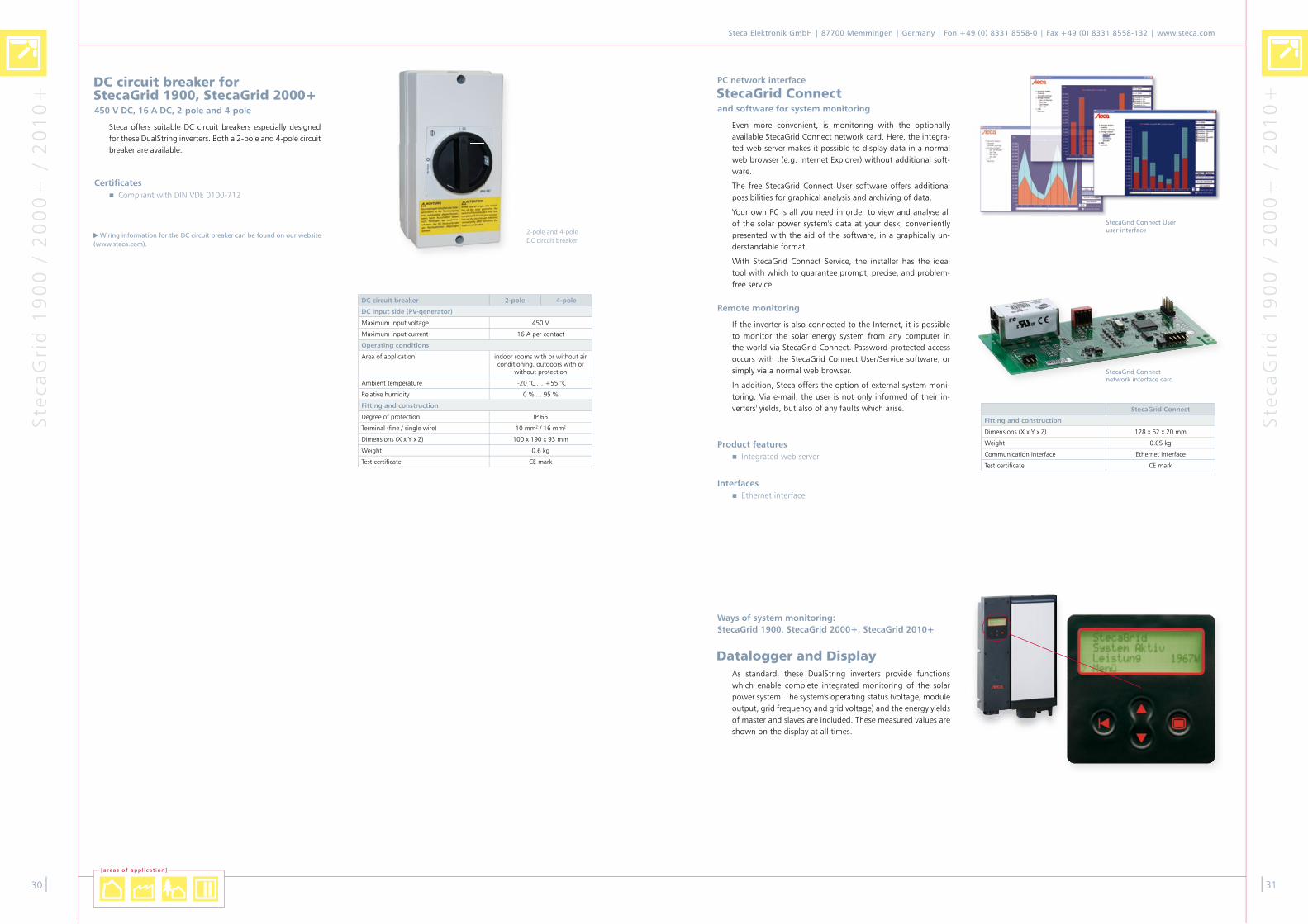
StecaGrid Connect User user interface
PC network interface
StecaGrid Connect and software for system monitoring
Even more convenient, is monitoring with the optionally available StecaGrid Connect network card. Here, the integra-ted web server makes it possible to display data in a normal web browser (e.g. Internet Explorer) without additional soft-ware.
The free StecaGrid Connect User software offers additional possibilities for graphical analysis and archiving of data.
Your own PC is all you need in order to view and analyse all of the solar power system's data at your desk, conveniently presented with the aid of the software, in a graphically un-derstandable format.
With StecaGrid Connect Service, the installer has the ideal tool with which to guarantee prompt, precise, and problem-free service.
Remote monitoring
If the inverter is also connected to the Internet, it is possible to monitor the solar energy system from any computer in the world via StecaGrid Connect. Password-protected access occurs with the StecaGrid Connect User/Service software, or simply via a normal web browser.
In addition, Steca offers the option of external system moni-toring. Via e-mail, the user is not only informed of their in-verters' yields, but also of any faults which arise.
StecaGrid Connect network interface card
StecaGrid Connect
Fitting and construction
Dimensions (X x Y x Z) 1�8 x 6� x �0 mm
Weight 0.05 kg
Communication interface Ethernet interface
Test certificate CE mark
Product featuresIntegrated web server
InterfacesEthernet interface
|�1
Ways of system monitoring: StecaGrid 1900, StecaGrid 2000+, StecaGrid 2010+
Datalogger and DisplayAs standard, these DualString inverters provide functions which enable complete integrated monitoring of the solar power system. The system's operating status (voltage, module output, grid frequency and grid voltage) and the energy yields of master and slaves are included. These measured values are shown on the display at all times.
DC circuit breaker for StecaGrid 1900, StecaGrid 2000+450 V DC, 16 A DC, 2-pole and 4-pole
Steca offers suitable DC circuit breakers especially designed for these DualString inverters. Both a �-pole and 4-pole circuit breaker are available.
DC circuit breaker 2-pole 4-pole
DC input side (PV-generator)
Maximum input voltage 450 V
Maximum input current 16 A per contact
Operating conditions
Area of application indoor rooms with or without air conditioning, outdoors with or
without protection
Ambient temperature -�0 °C … +55 °C
Relative humidity 0 % ... 95 %
Fitting and construction
Degree of protection IP 66
Terminal (fine / single wire) 10 mm� / 16 mm�
Dimensions (X x Y x Z) 100 x 190 x 9� mm
Weight 0.6 kg
Test certificate CE mark
Wiring information for the DC circuit breaker can be found on our website (www.steca.com).
�-pole and 4-pole DC circuit breaker
[a reas of appl i cat ion]
CertificatesCompliant with DIN VDE 0100-71�

400
225
847
Stec
aGri
d 9
00
0 �
ph
/ 1
00
00
�p
h
Stec
aGri
d 9
00
0 �
ph
/ 1
00
00
�p
h
��|
Steca Elektronik GmbH | 87700 Memmingen | Germany | Fon +49 (0) 8331 8558-0 | Fax +49 (0) 8331 8558-132 | www.steca.com
|��
StecaGrid 9000 3ph
DC input side (PV-generator)
Maximum start voltage 8�0 V
Maximum input voltage 8�0 V
Minimum input voltage �50 V
Minimum input voltage for rated output
�50 V
MPP voltage �50 V … 680 V
Maximum input current �� A
Maximum input power 10,500 W
Maximum recommended PV power 1�,000 Wp
Derating / limiting automatic when- input power is higher- the device is not cooled sufficiently- input currents > ��A(higher currents are limited by the equipment and therefore will not damage the inverter)
AC output side (Grid connection)
Grid voltage �60 V … 440 V
Rated grid voltage 400 V
Maximum output current 17 A
Maximum output power 9,900 W
Rated power 9,000 W
Rated frequency 50 Hz
Frequency 47.5 Hz ... 50.� Hz
Night-time power loss < 1 W
Feeding phases three-phase
Distortion factor < 5 % (max. power)
Characterisation of the operating performance
Maximum efficiency 96.� %
European efficiency 95.� %
MPP efficiency > 99 %
Power derating at full power from 50 °C (Tamb)
Switch-on power �0 W
Standby power 9 W
Safety
Isolation principle no galvanic isolation, transformerless
Operating conditions
Area of application indoor rooms with or without air conditioning, outdoors with protection
Ambient temperature -�0 °C … +60 °C
Relative humidity 0 % … 95 %
Noise emission < 60 dBA
Fitting and construction
Degree of protection IP 54
DC Input side connection MultiContact MC4 (5 pairs)
AC output side connection Wieland RST�5i5 plug
Dimensions (X x Y x Z) 400 x 847 x ��5 mm
Weight 4� kg
Communication interface RS485 to Meteocontrol WEB‘log
DC circuit breaker yes
Cooling principle temperature-controlled fan
Test certificate CE mark, DK 5940
Advantage of three-phase feedingPower curve P shows the power fed in to the public electricity grid. The grey shaded area shows the energyto be stored in the inverter. The advantage of three-phase feeding is plain to see.
P
U1
U2U3
PU
P
U1
U2U3
PU
Single-phase feeding
Three-phase feeding
StecaGrid 9000 3ph Always symmetrical
The advantage of three-phase feeding is that the produced solar capacity is always symmetrically distributed on all three power conductors to the public power grid. This is the case across the whole output range offered by StecaGrid 9000 �ph. When designing a system, the laborious avoidance of an asymmetry of more than 4.6 kW through the appropriate selection of separate inverters is thus dispensed with. Sym-metrical feeding is greatly in the interests of energy supply companies. Lengthy discussions with such companies are therefore a thing of the past.
Long service live
While the voltage passes through zero on the grid-feeding phase, single-phase inverters must temporarily accommodate all energy supplied by the solar modules within the device. This is usually realised by electrolytic capacitors. These com-ponents influence the service life of an electronic device, due to the possibility of drying out.
With three-phase inverters, energy is fed into the grid on at least two phases at all times. Thus, the necessity of interme-diate storage of energy in the device is greatly reduced, which is of benefit to the system operator with regard to a longer service life (see figure on right hand side).
Flexible connection
Due to the wide input voltage range of �50 V to 800 V, and a maximum input current of �� A, all commonly available crystalline solar modules can be connected to the StecaGrid 9000 �ph in various configurations. Beyond this, the system is also approved for use with CdTe and CIS / CIGS thin-film modules. Five plug/socket pairs are available for flexible, me-chanical DC connection.
Easy handling
Despite its high output, the StecaGrid 9000 �ph is a wall-mounted device. Thanks to the high degree of protection, this inverter can be installed indoors or outdoors. Due to the integrated DC circuit breaker, installation work is made easier, and the installation time is reduced. It is not necessary to open the StecaGrid 9000 �ph during installation.
Product featuresHigh efficiency
UniString concept
Wide input voltage range
Three-phase, symmetrical grid feeding
Low DC discharge currents due to special switching concept
Integrated DC circuit breaker
Robust metal casing
Suitable for outdoor installation
Wall-mounting with steel wall bracket for very easy installation
[areas of application]
Electronic protection functionsIntegrated temperature monitoring with output derating
DisplaysMulti-coloured LED shows operating states
OptionsSystem monitoring with WEB’log data loggers

225
847
400
Stec
aGri
d 9
00
0 �
ph
/ 1
00
00
�p
h
Stec
aGri
d 9
00
0 �
ph
/ 1
00
00
�p
h
�4|
Steca Elektronik GmbH | 87700 Memmingen | Germany | Fon +49 (0) 8331 8558-0 | Fax +49 (0) 8331 8558-132 | www.steca.com
|�5
StecaGrid 10 000 3phStecaGrid 10 000 3ph Always symmetrical
The advantage of three-phase feeding is that the produced solar capacity is always symmetrically distributed on all three power conductors to the public power grid. This is the case across the whole output range offered by StecaGrid 10 000 �ph. When designing a system, the laborious avoidance of an asymmetry of more than 4.6 kW through the appropriate selection of separate inverters is thus dispensed with. Sym-metrical feeding is greatly in the interests of energy supply companies. Lengthy discussions with such companies are therefore a thing of the past.
Long service live
While the voltage passes through zero on the grid-feeding phase, single-phase inverters must temporarily accommodate all energy supplied by the solar modules within the device. This is usually realised by electrolytic capacitors. These com-ponents influence the service life of an electronic device, due to the possibility of drying out.
With three-phase inverters, energy is fed into the grid on at least two phases at all times. Thus, the necessity of interme-diate storage of energy in the device is greatly reduced, which is of benefit to the system operator with regard to a longer service life (see figure on right hand side).
Flexible connection
Due to the wide input voltage range of �50 V to 845 V, and a maximum input current of �� A, all commonly available crystalline solar modules can be connected to the StecaGrid 10 000 �ph in various configurations. Beyond this, the system is also approved for use with CdTe and CIS / CIGS thin-film modules. Five plug/socket pairs are available for flexible, me-chanical DC connection.
Easy handling
Despite its high output, the StecaGrid 10 000 �ph is a wall-mounted device. Thanks to the high degree of protection, this inverter can be installed indoors or outdoors. Due to the integrated DC circuit breaker, installation work is made easier, and the installation time is reduced. It is not necessary to open the StecaGrid 10 000 �ph during installation.
Product featuresHigh efficiency
UniString concept
Wide input voltage range
Three-phase, symmetrical grid feeding
Low DC discharge currents due to special switching concept
Integrated DC circuit breaker
Robust metal casing
Suitable for outdoor installation
Wall-mounting with steel wall bracket for very easy installation
[e insatzbere iche]
Advantage of three-phase feedingPower curve P shows the power fed in to the public electricity grid. The grey shaded area shows the energyto be stored in the inverter. The advantage of three-phase feeding is plain to see.
P
U1
U2U3
PU
P
U1
U2U3
PU
Single-phase feeding
Three-phase feeding
DC input side (PV-generator)
Maximum start voltage 845 V
Maximum input voltage 845 V
Minimum input voltage �50 V
Minimum input voltage for rated output
�50 V
MPP voltage �50 V … 700 V
Maximum input current �� A
Maximum input power 10,800 W
Maximum recommended PV power 1�,500 Wp
Derating / limiting automatic when- input power is higher- the device is not cooled sufficiently- input currents > ��A(higher currents are limited by the equipment and therefore will not damage the inverter)
AC output side (Grid connection)
Grid voltage ��0 V … 480 V[depending on the regional settings]
Rated grid voltage 400 V
Maximum output current 17.7 A
Maximum output power 10,�00 W
Rated power 9,500 W
Rated frequency 50 Hz
Frequency 47.5 Hz ... 5� Hz [depending on regional settings]
Night-time power loss < 1 W
Feeding phases three-phase
Distortion factor < 5 % (max. power)
Characterisation of the operating performance
Maximum efficiency 96.� %
European efficiency 95.4 %
MPP efficiency > 99 %
Power derating at full power from 50 °C (Tamb)
Switch-on power �0 W
Standby power 9 W
Safety
Isolation principle no galvanic isolation, transformerless
Grid monitoring MSD compliant with DIN VDE 01�6-1-1
Operating conditions
Area of application indoor rooms with or without air conditioning, outdoors with protection
Ambient temperature -�0 °C … +60 °C
Relative humidity 0 % … 95 %
Noise emission < 60 dBA
Fitting and construction
Degree of protection IP 54
DC Input side connection MultiContact MC4 (5 pairs)
AC output side connection Wieland RST�5i5 plug
Dimensions (X x Y x Z) 400 x 847 x ��5 mm
Weight 4� kg
Communication interface RS485, USB
DC circuit breaker yes
Cooling principle temperature-controlled fan
Test certificate CE mark
Electronic protection functionsIntegrated temperature monitoring with output derating
DisplaysMulti-coloured LED shows operating states
OptionsCan be connected to the StecaGrid Vision display unit
System monitoring with WEB’log data loggers

Professional remote monitoring with
meteocontrol WEB‘logExperience gained from 480 MWp monitored systems
Area of applicationRemote monitoring of photovoltaic systems
Product featuresSolar management
Web portal in several languagesConvenient evaluation of measurement dataHigh-performance report generatorTarget/actual comparison of energy yieldOnline values
Safer‘Sun info
Access to your system via your own homepageAdministration and allocation of guest accessYou can integrate evaluations and diagrams in your website
Safer‘Sun portal
The Safer‘Sun portal can be adapted to your own corporate designCustom-made to your wishes and requirements
AdvantagesBest energy yield
Innovative and intelligent technology
Maximum safety
Guaranteed pay-back!
—
—
—
—
—
—
—
—
—
—
Functional principle of meteocontrol WEB‘log
Stec
aGri
d 9
00
0 �
ph
/ 1
00
00
�p
h
Stec
aGri
d 9
00
0 �
ph
/ 1
00
00
�p
h
�6|
Steca Elektronik GmbH | 87700 Memmingen | Germany | Fon +49 (0) 8331 8558-0 | Fax +49 (0) 8331 8558-132 | www.steca.com
|�7
Meteocontrol WEB‘log
StecaGrid 9000 3ph
StecaGrid 9000 3ph
StecaGrid 9000 3ph++
StecaGrid Vision Display unit
One photovoltaic system – one display
The philosophy behind the StecaGrid Vision display unit is to provide the system operator with a representation of the entire system's data. In the default display, the output and yields of all connected StecaGrid 9000 �ph devices are shown as combined totals. Thus, the operator does not need to go from one inverter to the next, reading out the values individu-ally and adding them up themselves. Naturally, it is also pos-sible to view and compare data from individual inverters.
Up to 20 inverters can be connected
One to �0 StecaGrid 9000 �ph inverters can be connected to the optional StecaGrid Vision display unit. The wired con-nections between the inverters and to the display unit are realised via Steca's own communication bus.
Easy to operate
The StecaGrid Vision impresses with its design. It is operated by means of four modern capacitive buttons. Graphic curves show the energy yields from the system as a whole, and from individual inverters, thus providing information at a glance, regarding the performance over the course of the day. In ad-dition, StecaGrid Vision has a data logging function, which also enables querying of historical data. Error messages re-garding the system as a whole, as well as individual inverters, are shown in plain text.
Product featuresIntegrated data logger
DisplayMultifunction graphic LCD display with backlighting
for current output, energy yields, operating parameters, date, time, service information
Animated representation of yield
OperationMultilingual menu navigation
—
Interconnection
StecaGrid 10 000 3ph UniString inverters and StecaGrid Vision display unit:
StecaGrid Vision
StecaGrid 10 000 3ph
StecaGrid 10 000 3ph
StecaGrid 10 000 3ph
... max. 20 x StecaGrid 10 000 3ph
++
58.8
180
24063.8
StecaGrid Vision
Application conditions
Area of application indoor rooms, with or without air conditioning
Interface to StecaGrid 10 000 �ph Steca bus with max. 1,000 m cable length
Ambient temperature -�0 °C ... +45 °C
Humidity 0 % ... 95 %
Noise emissions in standard operating conditions
silent
Equipment and design
Protection class IP �0
Dimensions (X x Y x Z) �40 x 180 x 6�,8 mm
Weight 450 g
Power supply ��0 V mains adapter plug (included in delivery)
Communication interface USB, optional ethernet
Range 1,000 m
Test certificate CE mark

Serv
ice
Soft
war
e
�8|
Steca Elektronik GmbH | 87700 Memmingen | Germany | Fon +49 (0) 8331 8558-0 | Fax +49 (0) 8331 8558-132 | www.steca.com
|�9
Service-Information for StecaGrid inverters
Naturally we will provide you with our expert advice and sup-port after your purchase, during installation, and during the long years of operation of your PV system.
Replacement service
The modular design of the StecaGrid system, along with our rapid replacement service, ensure that your solar power sys-tem feeds the grid with maximum yields. In case of a Ste-caGrid inverter malfunctioning, it will be exchanged with a corresponding replacement device as quickly as possible by Steca or a Steca service partner (‚advance replacement‘). In this way, any loss of grid-feed remuneration is kept to a mini-mum if servicing is required.
Manufacturer’s guarantee
Our StecaGrid products come with a 5-year commercial gua-rantee as standard. Furthermore, we offer the system opera-tor the chance to take out an extended guarantee of 10 years. You will find the extended guarantee with each product.
Replacement devices after the guarantee period
Even after the guarantee period is over, with our replacement devices at low inclusive prices, we help to ensure the continu-ed economic efficiency of your solar power system
Monitoring
If your solar power system is equipped with the relevant com-munication devices, it is possible to monitor your system re-motely. Just ask for further information.
Training
According to your requirements, and upon consultation, we can offer you training on our StecaGrid products, system con-figuration, or data communication
The dates of upcoming training sessions for installers can be found on our website.
Contact
In addition to the contact details you have, our hotline is available to you:
– Fon: +49 (0) 700 StecaGrid +49 (0) 700 78���474�
– Fax: +49 (0) 8��1 8558-1��
– E-Mail: [email protected]
Here you can get support without delay.
Service
Professional system dimensioning ... with StecaGrid Configurator 3.0
The update version of the StecaGrid Configurator makes it possible to plan a photovoltaic system in an even more professional manner. It offers a wealth of improvements compared to its forerunner, the �.� version.
This version is self-contained and functions indepen-dently of Microsoft Excel, offering a convenient user interface. There are four different options for deter-mining the size of a photovoltaic system after selec-ting a module type. In addition, modules stored in a large database can be filtered according to specific criteria. This is followed by the selection of MiniSt-ring, DualString and UniString inverters according to a range of specifications, for example the installa-tion site and rated AC or DC power. The calculated cost of generating electricity is taken as the standard selection criterion. To help with the specifications, the programme includes different values for the cost of systems planning as well as for modules, wiring, installation systems, etc. The installing company can provide their client data and company logo, which will appear on the printouts. A total of �0 locations throughout Germany offer irradiation data to help predict annual energy yield.
The predicted annual energy yield and the similarly editable values for the discount factor and operating time together allow the exact calculation in cents per kilowatt hour of the costs incurred by a system in producing electricity. On the basis of the electrici-ty generation costs, it is possible to ascertain at a glance whether it would be more efficient to use the inverter with one more solar module, or one fewer. A list of required parts, the connection diagram and a summary of the project data all guarantee professio-nal preparation for sales meetings with customers.
The software is available free of charge at www.steca.com.
40|
Steca Elektronik GmbH | 87700 Memmingen | Germany | Fon +49 (0) 8331 8558-0 | Fax +49 (0) 8331 8558-132 | www.steca.com
|41
"From the assembly of the compo-nents to the finished device – from the development to the
after-sales service."
Not without reason is Steca listed as an authority for energy generation in the German federal government's environmental technology atlas “Green Tech made in Germany”. Products in the area of solar electronics facilitate environmentally-friend-ly use of clean and free solar energy. Today, in the photovoltaic and solar thermal energy sectors, over 1.5 million controllers manage and control solar energy systems around the world.
The company contributes to energy savings with the millions of electronic components it produces for devices classified in energy efficiency class A++, such as motion detectors or network circuit brea-kers. Devices for water and weather measuring technology facilitate further research into our envi-ronment. Electronics utilised in the fields of medi-cine and industry regulate analysis and production processes and thereby save energy and materials. Further examples include photovoltaic controllers for improving the energy balance in automobile appli-cations. All battery-operated devices are developed for minimum electricity consumption with maximum output.
Steca environmental policy is based on sustainabili-ty and environmental compatibility, with a view to providing services and producing products for an ecological future. The company takes account of the whole value-added chain and involves suppliers and customers. Steca is certified in accordance with ISO 14001:�004 and organised in accordance with the EU Environmental Management and Audit Scheme.
Environmental protection in series We are thinking of tomorrow
For Steca, there are many aspects to environmental and climate protection and the resultant reduction in CO� and environmental poisons.
With Steca charging technology, the devices in batte-ry charging systems use the maximum energy storage potential and treat damaged or totally discharged batteries. Complete management systems for bus maintenance facilities help prevent environmental pollution by reducing cold-run phases.
In addition to the obvious need to apply environ-mentally-friendly processes, electronic products from Steca contribute both to reducing energy consump-tion and environmental pollution around the world, as well as to spreading the use of regenerative ener-gy sources by means of solar technology.
Sola
r Th
erm
al
PV O
ff G
rid
Modem Modem
4�|
Steca Elektronik GmbH | 87700 Memmingen | Germany | Fon +49 (0) 8331 8558-0 | Fax +49 (0) 8331 8558-132 | www.steca.com
|4�
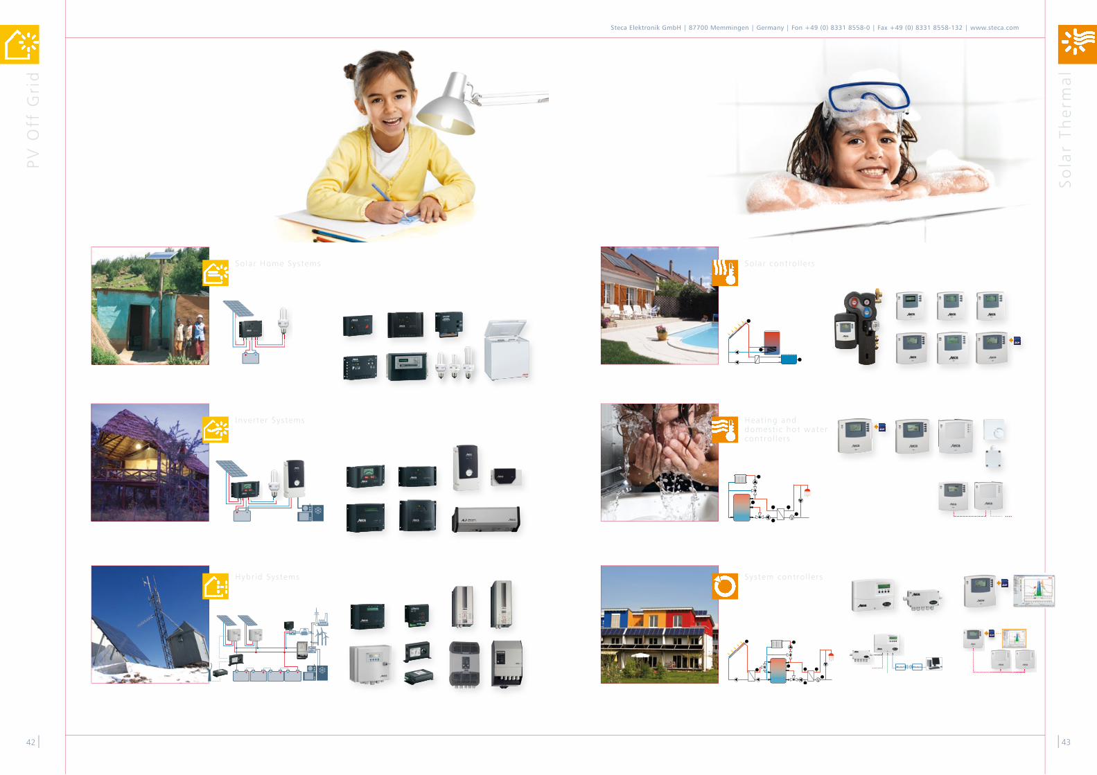
Solar control lers
Heat ing and domest ic hot water control lers
System control lers
Solar Home Systems
Inverter Systems
Hybr id Systems

Ro
om
fo
r N
ote
s
Bat
tery
Ch
arg
ing
Co
ntr
oll
ers
44|
Steca Elektronik GmbH | 87700 Memmingen | Germany | Fon +49 (0) 8331 8558-0 | Fax +49 (0) 8331 8558-132 | www.steca.com
|45
Mobi le Use
Stat ionary Use
Equipment

Sym
bo
ls
Ro
om
fo
r N
ote
s
46|
Steca Elektronik GmbH | 87700 Memmingen | Germany | Fon +49 (0) 8331 8558-0 | Fax +49 (0) 8331 8558-132 | www.steca.com
|47
Symbols
PV Grid Connected
Inverter with low power
UniString inverterinverter with one MPP tracker per device
Inverter with average power
Inverter with high power
MiniString inverterinverter for small strings with one MPP tracker per device
DualString inverterinverter with two MPP trackers per device
Softwarefor system dimensioning
Exclusion of liability
Steca Elektronik GmbH reserves the right to supplement and change the product range offered in the catalogue, or to remove products from the range. Please contact Steca if you require additional or more up-to-date product information. The information in this catalogue is not exhaustive. We compiled this information with care. In spite of this, it may not have been updated or may no longer be applicable in individual cases. We accept no liability for imprecise or missing information in this catalogue.
Copyright Steca Elektronik GmbH ("Steca"). Steca is a protected trademark of Steca Elektronik GmbH. This trademark may only be used by third parties with our express prior permission. The sole owner of the rights to the images and logos and texts is Steca. Steca allows the free use of product pictures and graphics in the context of the presentation of its own products, as long as neither product pictures nor graphics are altered or edited, in particular with regard to cropping, modification, distortion or other deformations. The permission of Steca must always be gained for any other commercial use. "Steca Elektronik GmbH" must always be indicated as the source of the images. In return for the provision of the pictures free of charge, Steca requests a sample copy when they are used in print media, and a brief notification when they are used in film and electronic media. You agree that this agreement does not require a signature in order to become valid. The pertinent laws of the Federal Republic of Germany apply for the use of this catalogue by third parties and the use of the corres-ponding terms and conditions.
Images from Steca, www.burger-fotodesign.de, www.photocase.com and www.marx-studios.de and www.fotolia.com.
Information
Specialist in "difficult roofs"Systems for shading and differently aligned roof surfaces
Commercial systemsfor agriculture and industry and ground-mounted installation
Residential systemssingle-family houses, apartment buildings, carports and garages

english
www.steca.com
„PV Grid Connected – Power from the sun for everyday use.“
Steca Elektronik GmbHMammostraße 1
87700 MemmingenGermany
Fon +49 (0) 8331 8558-0Fax +49 (0) 8331 8558-132
PV Grid Connected732.677 | 14.2010© by Steca
www.steca.com