english simovert p 6se21 series inverters operating ... · pdf filesimovert p 6se21 series...
TRANSCRIPT

SIMOVERT P 6SE21 Series Inverters
English
Operating Instructions
Siemens plc 1995 G85139–A1615–U156–A02.95
3
Contents Page
Warning and Caution Notes . . . . . . . . . . . . . . . . . . . . . . . . . . . . . . . . . . . . . . . . . . . . . . . . . . . . . . . . . . . . . . . . . . . . 5
1. DESCRIPTION . . . . . . . . . . . . . . . . . . . . . . . . . . . . . . . . . . . . . . . . . . . . . . . . . . . . . . . . . . . . . . . . . . . . . . . . . . . . 7
1.1 Introduction . . . . . . . . . . . . . . . . . . . . . . . . . . . . . . . . . . . . . . . . . . . . . . . . . . . . . . . . . . . . . . . . . . . . . . . . . . . . 1.2 Control Facilities . . . . . . . . . . . . . . . . . . . . . . . . . . . . . . . . . . . . . . . . . . . . . . . . . . . . . . . . . . . . . . . . . . . . . . . . 1.3 Monitoring Facilities . . . . . . . . . . . . . . . . . . . . . . . . . . . . . . . . . . . . . . . . . . . . . . . . . . . . . . . . . . . . . . . . . . . . . 1.4 Motor Characteristics . . . . . . . . . . . . . . . . . . . . . . . . . . . . . . . . . . . . . . . . . . . . . . . . . . . . . . . . . . . . . . . . . . . . 1.4.1 Voltage/Frequency Characteristic . . . . . . . . . . . . . . . . . . . . . . . . . . . . . . . . . . . . . . . . . . . . . . . . . . . . . . 1.4.2 Low Frequency Voltage Boost (Ku) . . . . . . . . . . . . . . . . . . . . . . . . . . . . . . . . . . . . . . . . . . . . . . . . . . . . 1.4.3 Current Limit . . . . . . . . . . . . . . . . . . . . . . . . . . . . . . . . . . . . . . . . . . . . . . . . . . . . . . . . . . . . . . . . . . . . . . . . 1.5 Options . . . . . . . . . . . . . . . . . . . . . . . . . . . . . . . . . . . . . . . . . . . . . . . . . . . . . . . . . . . . . . . . . . . . . . . . . . . . . . . .
78999
101010
2. TECHNICAL DATA . . . . . . . . . . . . . . . . . . . . . . . . . . . . . . . . . . . . . . . . . . . . . . . . . . . . . . . . . . . . . . . . . . . . . . . . . 11
2.1 Equipment Ratings Table . . . . . . . . . . . . . . . . . . . . . . . . . . . . . . . . . . . . . . . . . . . . . . . . . . . . . . . . . . . . . . . . . 2.2 Cable Lengths . . . . . . . . . . . . . . . . . . . . . . . . . . . . . . . . . . . . . . . . . . . . . . . . . . . . . . . . . . . . . . . . . . . . . . . . . .
1111
3. MECHANICAL INSTALLATION . . . . . . . . . . . . . . . . . . . . . . . . . . . . . . . . . . . . . . . . . . . . . . . . . . . . . . . . . . . . . . 12
4. ELECTRICAL INSTALLATION . . . . . . . . . . . . . . . . . . . . . . . . . . . . . . . . . . . . . . . . . . . . . . . . . . . . . . . . . . . . . . . 14
4.1 Mains Input / Motor Connections . . . . . . . . . . . . . . . . . . . . . . . . . . . . . . . . . . . . . . . . . . . . . . . . . . . . . . . . . . 4.2 Control Connections . . . . . . . . . . . . . . . . . . . . . . . . . . . . . . . . . . . . . . . . . . . . . . . . . . . . . . . . . . . . . . . . . . . . .
1416
5. COMMISSIONING . . . . . . . . . . . . . . . . . . . . . . . . . . . . . . . . . . . . . . . . . . . . . . . . . . . . . . . . . . . . . . . . . . . . . . . . . . 18
5.1 Preparation for Switch–On . . . . . . . . . . . . . . . . . . . . . . . . . . . . . . . . . . . . . . . . . . . . . . . . . . . . . . . . . . . . . . . 5.1.1 Starting and Stopping the Inverter . . . . . . . . . . . . . . . . . . . . . . . . . . . . . . . . . . . . . . . . . . . . . . . . . . . . . 5.1.2 Direction of Rotation . . . . . . . . . . . . . . . . . . . . . . . . . . . . . . . . . . . . . . . . . . . . . . . . . . . . . . . . . . . . . . . . . 5.1.3 Jog Feature . . . . . . . . . . . . . . . . . . . . . . . . . . . . . . . . . . . . . . . . . . . . . . . . . . . . . . . . . . . . . . . . . . . . . . . . 5.1.4 Speed Control . . . . . . . . . . . . . . . . . . . . . . . . . . . . . . . . . . . . . . . . . . . . . . . . . . . . . . . . . . . . . . . . . . . . . . 5.2 First Switch–On . . . . . . . . . . . . . . . . . . . . . . . . . . . . . . . . . . . . . . . . . . . . . . . . . . . . . . . . . . . . . . . . . . . . . . . . . 5.3 Parameterisation . . . . . . . . . . . . . . . . . . . . . . . . . . . . . . . . . . . . . . . . . . . . . . . . . . . . . . . . . . . . . . . . . . . . . . . . 5.3.1 Changing Parameter Settings . . . . . . . . . . . . . . . . . . . . . . . . . . . . . . . . . . . . . . . . . . . . . . . . . . . . . . . . . 5.3.2 Parameter Descriptions . . . . . . . . . . . . . . . . . . . . . . . . . . . . . . . . . . . . . . . . . . . . . . . . . . . . . . . . . . . . . . 5.4 Fault Indications . . . . . . . . . . . . . . . . . . . . . . . . . . . . . . . . . . . . . . . . . . . . . . . . . . . . . . . . . . . . . . . . . . . . . . . . 5.5 Fault Relay . . . . . . . . . . . . . . . . . . . . . . . . . . . . . . . . . . . . . . . . . . . . . . . . . . . . . . . . . . . . . . . . . . . . . . . . . . . . .
1818202020202121223031
6. USING CLOSED LOOP SPEED CONTROL . . . . . . . . . . . . . . . . . . . . . . . . . . . . . . . . . . . . . . . . . . . . . . . . . . . 32
6.1 Introduction . . . . . . . . . . . . . . . . . . . . . . . . . . . . . . . . . . . . . . . . . . . . . . . . . . . . . . . . . . . . . . . . . . . . . . . . . . . . 6.2 Installation of Control Loop Speed Control . . . . . . . . . . . . . . . . . . . . . . . . . . . . . . . . . . . . . . . . . . . . . . . . . . 6.2.1 Scaling Factor of ‘Actual Speed’ . . . . . . . . . . . . . . . . . . . . . . . . . . . . . . . . . . . . . . . . . . . . . . . . . . . . . . . 6.2.2 Speed Control Operation . . . . . . . . . . . . . . . . . . . . . . . . . . . . . . . . . . . . . . . . . . . . . . . . . . . . . . . . . . . . . 6.2.3 Speed Control Optimisation . . . . . . . . . . . . . . . . . . . . . . . . . . . . . . . . . . . . . . . . . . . . . . . . . . . . . . . . . . . 6.2.4 Slip Limit (P35) . . . . . . . . . . . . . . . . . . . . . . . . . . . . . . . . . . . . . . . . . . . . . . . . . . . . . . . . . . . . . . . . . . . . . . 6.2.5 Sample Rate (P36) . . . . . . . . . . . . . . . . . . . . . . . . . . . . . . . . . . . . . . . . . . . . . . . . . . . . . . . . . . . . . . . . . .
32323233333333
7. QUICK REFERENCE GUIDE . . . . . . . . . . . . . . . . . . . . . . . . . . . . . . . . . . . . . . . . . . . . . . . . . . . . . . . . . . . . . . . . 34
7.1 Connections . . . . . . . . . . . . . . . . . . . . . . . . . . . . . . . . . . . . . . . . . . . . . . . . . . . . . . . . . . . . . . . . . . . . . . . . . . . . 7.2 Parameter List . . . . . . . . . . . . . . . . . . . . . . . . . . . . . . . . . . . . . . . . . . . . . . . . . . . . . . . . . . . . . . . . . . . . . . . . . . 7.3 Fault Codes . . . . . . . . . . . . . . . . . . . . . . . . . . . . . . . . . . . . . . . . . . . . . . . . . . . . . . . . . . . . . . . . . . . . . . . . . . . .
343535
SIMOVERT P 6SE21 Series Inverters
English
Operating Instructions
Siemens plc 1995G85139–A1615–U156–A02.95
4
Contents (continued) Page
Figures
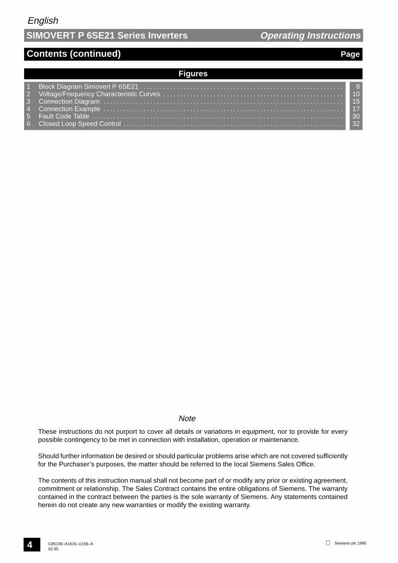
1 Block Diagram Simovert P 6SE21 . . . . . . . . . . . . . . . . . . . . . . . . . . . . . . . . . . . . . . . . . . . . . . . . . . . . . . . . . . . . 2 Voltage/Frequency Characteristic Curves . . . . . . . . . . . . . . . . . . . . . . . . . . . . . . . . . . . . . . . . . . . . . . . . . . . . . . 3 Connection Diagram . . . . . . . . . . . . . . . . . . . . . . . . . . . . . . . . . . . . . . . . . . . . . . . . . . . . . . . . . . . . . . . . . . . . . . . . 4 Connection Example . . . . . . . . . . . . . . . . . . . . . . . . . . . . . . . . . . . . . . . . . . . . . . . . . . . . . . . . . . . . . . . . . . . . . . . . 5 Fault Code Table . . . . . . . . . . . . . . . . . . . . . . . . . . . . . . . . . . . . . . . . . . . . . . . . . . . . . . . . . . . . . . . . . . . . . . . . . . . 6 Closed Loop Speed Control . . . . . . . . . . . . . . . . . . . . . . . . . . . . . . . . . . . . . . . . . . . . . . . . . . . . . . . . . . . . . . . . . .
81015173032
Note
These instructions do not purport to cover all details or variations in equipment, nor to provide for everypossible contingency to be met in connection with installation, operation or maintenance.
Should further information be desired or should particular problems arise which are not covered sufficientlyfor the Purchaser’s purposes, the matter should be referred to the local Siemens Sales Office.
The contents of this instruction manual shall not become part of or modify any prior or existing agreement,commitment or relationship. The Sales Contract contains the entire obligations of Siemens. The warrantycontained in the contract between the parties is the sole warranty of Siemens. Any statements containedherein do not create any new warranties or modify the existing warranty.

SIMOVERT P 6SE21 Series Inverters
English
Operating Instructions
Siemens plc 1995 G85139–A1615–U156–A02.95
5
Warning and Caution Notes
This equipment contains hazardous voltages and controls hazardous rotating mechanical parts. Lossof life, severe personal injury or property damage can result if instructions contained in this manualare not followed.
Only suitable qualified personnel should work on this equipment, and only after becoming familiar withall safety notices, installation, operation and maintenance procedures contained in this manual. Thesuccessful and safe operation of this equipment is dependent upon its proper handling, installation,operation and maintenance.
WARNING
Definitions
• Qualified Person
For the purposes of this manual and product labels, a qualified person is one who is familiar with the installation,construction, operation and maintenance of this equipment and with the hazards involved. In addition, the person mustbe:
(1) Trained and authorised to energise, de–energise, clear, ground and tag circuits and equipment inaccordance with established safety practices.
(2) Trained in the proper care and use of protective equipment in accordance with established safetypractices.
(3) Trained in rendering first aid.
• DANGER
For the purposes of this manual and product labels, DANGER indicates that loss of life, severe personal injury orsubstantial property damage WILL result if proper precautions are not taken.
• WARNING
For the purposes of this manual and product labels, WARNING indicates that loss of life, severe personal injury orsubstantial property damage CAN result if proper precautions are not taken.
• CAUTION
For the purposes of this manual and product labels, CAUTION indicates that minor personal injury or property damageCAN result if proper precautions are not taken.
• Note
For the purposes of this manual and product labels, Notes merely call attention to information that is especiallysignificant in understanding and operating the drive.

SIMOVERT P 6SE21 Series Inverters
English
Operating Instructions
Siemens plc 1995G85139–A1615–U156–A02.95
6
Hot LineSiemens operates a telephone ‘hot line’ for users of their 6SE21 range of
inverters. This service is available during normal working hours, Monday toFriday. If you require assistance, contact our customer support personnel
on the following number:
Tel: (49) 9131 7 23212Fax: (49) 9131 7 29900
Please have the following information available before dialling:• inverter model number
• hardware type (stored in P49)• software version (stored in P50)

SIMOVERT P 6SE21 Series Inverters
English
Operating Instructions
Siemens plc 1995 G85139–A1615–U156–A02.95
7
1. DESCRIPTION
SIMOVERT P transistorised voltage–source inverters operate with high voltages.
Connection, commissioning and fault–finding should only be carried out by qualified personnel whoare fully conversant with the relevant documentation, installation regulations, etc.
Only permanently–wired input power connections are allowed. This equipment must be grounded(IEC 536 Class 1, NEC and other applicable standards).
Safety Note:Do not apply input power to the equipment when the plastic cover has been removed. Dangerousvoltages are present within the equipment which could cause serious injury or death if touched. Afterremoving mains power, always allow a minimum of five minutes for the internal capacitors todischarge before removing the cover.
When the 3–phase mains input is protected by a current–operated earth–leakage breaker, the inputto the inverter must be isolated from the mains if the earth–leakage breaker is to operate effectively.
The dc–link capacitors remain charged to dangerous voltages for up to five minutes after the incomingpower has been switched off.
When the motor is not running, dangerous voltages are still present on the power input terminals ANDmotor output terminals and also on the dc–link terminals.
Under certain set–up conditions, the inverter may restart automatically after an input power failure.
WARNING
1.1 IntroductionSIMOVERT P inverters of the 6SE21 series are designed for low–loss speed control of three–phase motors. This isachieved by rectifying input voltage to establish a dc link voltage, and modulating this link voltage with a three–phasetransistor bridge to produce a Pulse–Width Modulated (PWM) three–phase output voltage (see Figure 1). Theinductance of the motor windings converts this PWM voltage to a sinusoidal motor current. By varying the frequency ofthis sinusoidal current, the rotational speed of the motor is controlled without significantly affecting the losses in themotor. The output frequency can be adjusted between 0 and 400 Hz.

SIMOVERT P 6SE21 Series Inverters
English
Operating Instructions
Siemens plc 1995G85139–A1615–U156–A02.95
8
Block Diagram – SIMOVERT P 6SE21Figure 1:
3
M
PWM
SE
PROM
CPUA/D
D/A
SV
SI
GR
ZK
WR
Run/Stop
0 – 10 V0 – 20 mA4 – 20 mA
BUS
+
Power Supply
Mains Fuse(s)DC LinkPower SupplyMicroprocessorAnalog/Digital ConverterBus Connector
GR RectifierWR InverterSE Current MonitoringPWM Pulse Width ModulatorD/A Digital/Analog ConverterR/L Clockwise/Counter–clockwise
Frequency, Current Indicator
Jog
FRONTPANEL
Fu/Iu
PROM
Fault
Trip
Tacho
Fu/Iu
P
RS485
X11 X1
X1
ZK
CPUA/DBUS
+15 V
+10 V
2
3
4
1367
9
12
11
161718
1920
21
1415
SI
SV
R/L 5
1.2 Control Facilities
The inverter can be started/stopped by any of the following means (see parameter P05 in section 5.3.2 and also Figure3):
(1) Connection of a latching switch to the run/stop input (terminals X11.2/3).
(2) Applying a rising edge (i.e. momentary push–button) to the Run/Stop input (terminals X11.2/3) and a fallingedge to the trip input terminal X11.2/4.
(3) Connection of a voltage level of 7 – 33 V to the Run/Stop input (terminals X11.3/1).
(4) Automatic starting on application of input power (shorting link terminals X11.2/3).
(5) Connection of a voltage level of 7 – 33 V to the jog input (terminal X11.13/1).
(6) Control via the serial I/O connections.

SIMOVERT P 6SE21 Series Inverters
English
Operating Instructions
Siemens plc 1995 G85139–A1615–U156–A02.95
9
The output frequency of the inverter, and hence the speed of the motor, can be controlled by any of the following means(see 5.3.2, parameter P04 and also Figure 3):
(1) Connection of 0–10 V control voltage (terminals X11.7/8).
(2) Connection of a 0–20 mA current loop control input (terminals X11.9/10).
(3) Connection of a 4–20 mA current loop control input (terminals X11.9/10).
(4) Connection of a 5 kΩ control potentiometer (terminals X11.6/7/8).
(5) By digital parameterisation via the push–buttons fitted to the inverter, or via equivalent external push–buttonsconnected to terminals X11.17 and X11.18.
(6) Via the serial I/O connection.
1.3 Monitoring FacilitiesThe following monitoring facilities are available:
(1) Seven–segment display for output frequency, output current, fault indication or parameterisation. This isviewed through a window in the cover.
(2) A 0–10 V analogue signal, proportional to output frequency or output current.
(3) A changeover relay, normally energised when the drive is connected to a suitable input supply. The relay isde–energised when a fault is indicated (see section 5.5).
(4) The drive may be interrogated via the serial I/O connection.
1.4 Motor CharacteristicsThe inverter can be adjusted to suit individual motor characteristics in the ways described in 1.4.1 and 1.4.2.
1.4.1 Voltage/Frequency Characteristic
Six voltage/frequency characteristic curves are available plus one programmable curve (see Figure 2). They areintended for the following applications:
Curve 0: VN/50 Hz (constant torque)For standard 50 Hz induction motors with linear speed/torque characteristics.
Curve 1: VN/60 Hz (constant torque)For standard 60 Hz induction motors with linear speed/torque characteristics.
Curve 2: VN/87 Hz (constant torque)For delta–connection of standard induction motors designed for star–connection of 50 Hz input voltage.This increases the speed range over which constant motor torque can be achieved.
Curve 3: VN/120 Hz (constant torque)For applications where a constant torque is required over the full operating speed range 0.1 to 120 Hz.
Curve 4*: VN/50 Hz (torque proportional to speed 1.5)For operation of 50 Hz motors driving loads where torque is proportional to (speed)1.5. Typical examplesof such loads are fans and pumps.
Curve 5*: VN/60 Hz (torque proportional to speed 1.5)For operation of 60 Hz motors driving loads where torque is proportional to (speed)1.5.
Curve 6*: Programmable (not shown in Figure 2)The curve type and corner frequency may be selected by the user.
* Curves 4 and 5 allow variable torque output current values (see section 2.1) to be loaded into parameter P17. Curve6 may allow variable torque output currents depending on the user–defined curve specified.

SIMOVERT P 6SE21 Series Inverters
English
Operating Instructions
Siemens plc 1995G85139–A1615–U156–A02.95
10
Figure 2: Voltage/Frequency Characteristic Curves
0 10 20 30 40 50 60 70 80 90 100 110 120
10
20
30
40
50
60
70
80
90
100
Voltage
%
Frequency
0
1 2 3
4
5
BoostKu
400
1.4.2 Low Frequency V oltage Boost (Ku)
The output voltage can be boosted in 0.1% steps up to 30% for low frequencies from 0 Hz. This may be required to giveadditional starting torque in some applications. The amount of voltage boost decreases linearly until 100% voltage isachieved.
If required, automatic boost may be used (see section 5.3.2, Parameter P19). This measures the motor characteristicsand selects a suitable boost voltage at first switch–on.
1.4.3 Current Limit
The maximum output current available from the inverter can be adjusted to provide thermal protection of the motorand/or limit the maximum motor torque (see section 5.3.2, parameters P17 and P18).
1.5 OptionsThe following options are available for use with 6SE21 inverters:
Sinewave Filter Module Part No. 6SE2100–1FC51/53/55NAMUR Interface Module Part No. 6SE2100–1FC50/52/54Relay Module * Part No. 6SE2100–1GA00Tachometer Interface Unit * Part No. 6SE2100–1DA00Clear Text Operator Panel * Part No. 6SE2100–1CA00
* These options cannot be fitted in combination with each other.

SIMOVERT P 6SE21 Series Inverters
English
Operating Instructions
Siemens plc 1995 G85139–A1615–U156–A02.95
11
2. TECHNICAL DATA
Rated supply voltage: Models 6SE21**–1AA11Models 6SE21**–3AA21
** – May be any number
1 AC 50/60 Hz +/–1%, 220 – 240 V +/–10%3 AC 50/60 Hz +/–1%, 380 – 500 V +/–10%
Output voltage 0 V – rated supply voltageOutput frequency 0.0 – 400 Hz
Efficiency ≥ 0.94Motor power factor ≤ 0.9 lagging/inductive
Ambient operating temperature(unit must not be exposed to direct sunlight)
0 – 40oC
Storage/transport temperature –30 – +85oCDegree of protection IP21 (NEMA 1)
Humidity 0 – 95% at 25oC
Frequency stability at Tmax 10oC referred to fmax Analogue setpoint 1%Digital setpoint 0.01%
Frequency resolution 0.1 Hz
Overload rating 1.5 x rated current for up to 60 seconds
2.1 Equipment Ratings T able
Model
6SE21..
InputVoltageRange
Max.Cont.Input
Current
CircuitBreaker
Constant TorqueOutput
Variable TorqueOutput **
Variable TorqueOutput **
460 V (USA)
Variable TorqueOutput **
500 V OverloadCurrentModel
6SE21..
VoltageRange
InputCurrent
BreakerContinuous
CurrentMotor
Rating *Continuous
CurrentMotor
Rating *Continuous
CurrentMotor
Rating *Continuous
CurrentMotor
Rating *
Current
01–1AA11198–264 V
1 phase
9.8 A 16.0 A 2.8 A .55 kW 3.9 A .75 kW – – – – 4.2 A
02–1AA11198–264 V
1 phase 13.5 A 16.0 A 3.9 A .75 kW 4.8 A 1.1 kW – – – – 5.8 A
03–1AA111 phase
26.5 A 32.0 A 6.8 A 1.5 kW 10.0 A 2.2 kW – – – – 10.2 A
03–3AA21 5.5 A 10.0 A 4.0 A 1.5 kW 5.5 A 2.2 kW 4.8 A 3 hp 4.8 A 2.2 kW 6.0 A
05–3AA21 10.0 A 16.0 A 7.6 A 3.0 kW 9.5 A 4.0 kW 8.1 A 5 hp 8.1 A 4.0 kW 11.4 A
08–3AA21 17.0 A 20.0 A 12.0 A 5.5 kW 17.0 A 7.5 kW 14.0 A 10 hp 12.0 A 7.5 kW 18.0 A
13–3AA21 342–550 V3 phase
28.0 A 32.0 A 19.0 A 7.5 kW 23.0 A 11.0 kW 21.0 A 15 hp 19.0 A 11.0 kW 28.5 A
17–3AA21342–550 V
3 phase 38.0 A 40.0 A 25.0 A 11.0 kW 32.0 A 15.0 kW 27.0 A 20 hp 25.0 A 15.0 kW 37.5 A
22–3AA21 40.0 A 50.0 A 32.0 A 15.0 kW 38.0 A 18.5 kW 34.0 A 25 hp 32.0 A 18.5 kW 48.0 A
27–3AA21 48.0 A 63.0 A 38.0 A 18.5 kW 46.0 A 22.0 kW 40.0 A 30 hp 38.0 A 22.0 kW 57.0 A
33–3AA21 70.0 A 80.0 A 46.0 A 22.0 kW 60.0 A 30.0 kW 52.0 A 40 hp 46.0 A 30.0 kW 69.0 A
42–3AA21 87.0 A 100.0 A 60.0 A 30.0 kW 75.0 A 37.0 kW 65.0 A 50 hp 60.0 A 37.0 kW 90.0 A
* Siemens 4–pole motor, 1LA5 series or equivalent.** Automatically selected on voltage/frequency curve types 4 and 5 (see section 1.4.1).
2.2 Cable LengthsThe inverters will operate satisfactorily with unscreened cables of up to 150 m in length and screened or armouredcable of up to 50 m in length. For applications where longer cables are required, inductors must be fitted to reducecapacitive currents.
NoteIf long cables are used, it may be necessary to change the value of parameter P52 to compensate for anyinaccuracies in the output current reading.
The following chokes are suitable for applications where up to 100/200 m screened/unscreened cables are required:
Model No. Choke Type6SE210*–1AA11 & 6SE2103–3AA21 4EP3601–8DB6SE2105–/6SE2108–3AA21 4EP3801–4DB6SE2113–/6SE2117–/6SE2122–3AA21 4EP3800–4DB6SE2127–/6SE2133–3AA21 4EP4002–1DB6SE2142–3AA21 4EU2421–8AA00

SIMOVERT P 6SE21 Series Inverters
English
Operating Instructions
Siemens plc 1995G85139–A1615–U156–A02.95
12
3. MECHANICAL INSTALLATION
High voltages are generated within this equipment. It must only be installed and operated by qualifiedpersonnel who are familiar with the equipment, its operating requirements and instructions.
The User is responsible for installation of the motor, drive controller, transformer and other devicesin accordance with regulations and local safety codes which may apply.
Adequate protective clothing (e.g. safety gloves, goggles, etc.) should be worn by the personinstalling this equipment.
Failure to observe the appropriate warnings and regulations may result in serious injury or death.
WARNING
The inverter must be installed in a vertical position and fixed to a solid surface via its four mounting holes. It is suitablefor wall–mounting or installation within a cubicle.
All inverter variants are air–cooled. Ensure that a free space of at least 100 mm (4 in.) is left both aboveand below the unit to allow an unimpeded air flow.
Avoid subjecting the inverter to excessive shock and vibration.
CAUTION
Installation drawings for the inverters are shown on the next page.

SIMOVERT P 6SE21 Series Inverters
English
Operating Instructions
Siemens plc 1995 G85139–A1615–U156–A02.95
13
Dimension Drawings
SIEMENS SIMOVERT
A
B
Control T erminals X1 1
Mains Input/Motor T erminals X1
All dimensions in millimetres
185
209197
144
257
197
293
SIEMENS SIMOVERT
A
B
375
325
225
249237
411
162
SIEMENS SIMOVERT
Exhaust Air
COOLING FAN
258
258
225
249237
172
561
667
190
A
SIEMENS SIMOVERT
258
258
225
249237
561
667
315
250
6SE2101–1AA116SE2102–1AA116SE2103–1AA11
6SE2103–3AA216SE2105–3AA216SE2108–3AA21
6SE2113–3AA216SE2117–3AA216SE2122–3AA216SE2127–3AA21
6SE2133–3AA216SE2142–3AA21
Notes:
A
B
B
A
B

SIMOVERT P 6SE21 Series Inverters
English
Operating Instructions
Siemens plc 1995G85139–A1615–U156–A02.95
14
4. ELECTRICAL INSTALLATION
Hazardous voltages of over 750 V are used in the operation of this equipment and can cause severepersonal injury or loss of life. The following precautions must be observed to reduce risk of injury ordeath:
• Only qualified service technicians should be allowed to test and repair the equipment or partsthereof.
• Keep all covers in place during normal operation.
• Defective discharge resistors of the dc–link circuit capacitors cause hazardous voltages toremain in the unit for some time. Make sure that the voltage has dropped below 50 V beforetouching any electrical contacts. Non–observance can lead to severe or fatal injury.
• During commissioning, should it be necessary to make measurements with the power turned on,do not touch any electrical contacts during such work and keep one hand completely free andoutside the electrical circuitry.
• Ensure that test equipment is in good and safe operating condition.
• Stand on an ESD–approved insulated surface while performing commissioning work with thepower on, being sure not to be grounded.
• When working on the connected motor or motor supply cable, ensure that the input power switchof the equipment for the external feed breaker is padlocked in the OFF position.
• All work on the equipment and its installation must be carried out in accordance with the locallyapplicable electrical wiring regulations. This includes proper grounding to ensure that noaccessible part of the equipment is at line or any other hazardous potential.
• The User is responsible for installation of the motor, drive controller, transformer and otherdevices in accordance with regulations and local safety codes which may apply. Pay specialattention to proper conductor sizing, fusing, grounding, isolating and disconnecting means andto overcurrent protection.
• Failure to ground the inverter properly can result in the surface of the equipment carryinghazardous voltages which may cause severe injury, loss of life or considerable damage toproperty.
WARNING
4.1 Mains Input / Motor Connections
Only qualified personnel who are familiar with the equipment, its operating instructions andrequirements should be allowed to install and operate this equipment.
Incorrect connection of the mains and motor leads (such as connecting the input to the output orconnecting excessive supply voltages to the input) will result in damage to the inverter.
WARNING
First, ensure that an input power supply of the correct voltage and current rating is available – see section 2. Next,ensure that the specified current rating fuse/overload circuit–breaker is connected between the input power sourceand the inverter.
The power inputs should be connected to X1 on the lower printed circuit board using a three or four–core cable and themotor should be connected using a four–core cable, both suitable for the currents specified in section 2.1. To connectthe cable, first remove the plastic cover of the drive by undoing the retaining screws or by levering the retaining clipsinwards with a screwdriver. Next, connect the cable to the terminal block X1 as shown in Figure 3.

SIMOVERT P 6SE21 Series Inverters
English
Operating Instructions
Siemens plc 1995 G85139–A1615–U156–A02.95
15
POWER TERMINALS: TERMINAL BLOCK X1
Single Phase Input Units:
ConnectionTerminalLabelling Function, Data, Notes
U1 X1.L1 MainsN1 X1.NPE X1. Ground
PE X1. GroundU2V2W2
X1.UX1.VX1.W
Motor connection 3AC 0 V ... Line voltage0.0 ... 400 Hz
M3
Three Phase Input Units:U1 X1.L1V1W1PE
X1.L2X1.L3X1. Ground
Mains connection 3AC 380 – 500 V +/–10%50/60 Hz
PE X1. GroundU2V2W2
X1.UX1.VX1.W
Motor connection0.0 ... 400 Hz
M
CONTROL TERMINALS: TERMINAL BLOCK X11
X11.1
X11.2
X11.3
X11.4
X11.5
X11.6
X11.7X11.8
X11.9
X11.10X11.11
X11.12
=+
24 V0 V 100 k connection to ground
Run/Stop Level or edge–triggered (P05)
+15 V
Forward/Reverse Closed = reverse
+10 V Ref. Reference voltage for potentiometer
0...10 V Frequency setpoint (voltage) (P04)0 V
0 (4)...20 mA Frequency setpoint (current) (P04)
0 V0...10 V Frequency/Output current indication
0...50 V Tachometer input
1AC 220 – 240 V +/–10% 50/60 Hz
5 k
=+
–
Tacho
3
Figure 3: Connection Diagram
X11.13 Jog Jog speed set by parameter P12
Ω
DC – Output X1.– Connections for Braking Module (EBM)DC + Output X1.+
Trip Can be used in conjunction with Run/Stopand with PTC
X11.14
X11.15X11.16X11.17
ARS485 Serial I/O connection
B‘P’ Button connection‘ ’ Button connection
X11.18 ‘ ’ Button connection
X11.2
X11.19
X11.20X11.21X11.22
NO Fault indication
COMNC0 V
(energised during normal operation)
3AC 0 V ... Line voltage
X11.2
Use Class 1 60/75oC copper wire only. The tightening torque for field wiring terminals is 1.5 Nm (M4).
max. load 5 mA (10 V fmax/Imax)
SIMOVERT P 6SE21 Series Inverters
English
Operating Instructions
Siemens plc 1995G85139–A1615–U156–A02.95
16
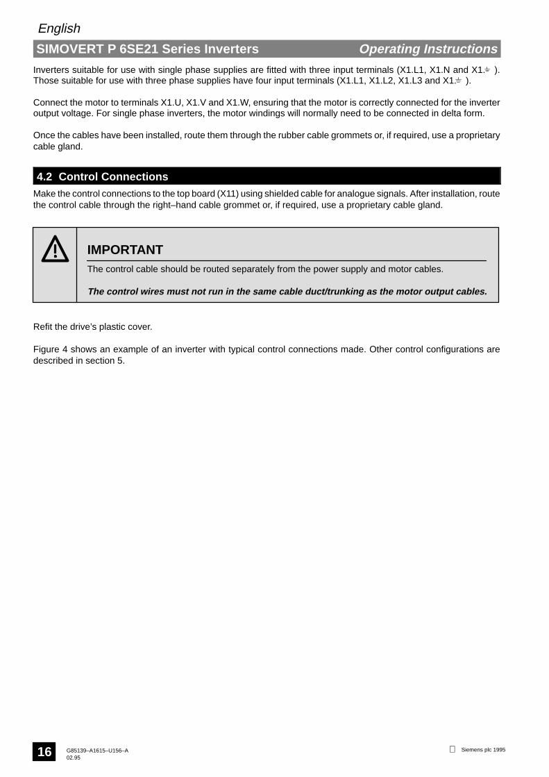
Inverters suitable for use with single phase supplies are fitted with three input terminals (X1.L1, X1.N and X1. ).Those suitable for use with three phase supplies have four input terminals (X1.L1, X1.L2, X1.L3 and X1. ).
Connect the motor to terminals X1.U, X1.V and X1.W, ensuring that the motor is correctly connected for the inverteroutput voltage. For single phase inverters, the motor windings will normally need to be connected in delta form.
Once the cables have been installed, route them through the rubber cable grommets or, if required, use a proprietarycable gland.
4.2 Control ConnectionsMake the control connections to the top board (X11) using shielded cable for analogue signals. After installation, routethe control cable through the right–hand cable grommet or, if required, use a proprietary cable gland.
The control cable should be routed separately from the power supply and motor cables.
The control wires must not run in the same cable duct/trunking as the motor output cables.
IMPORTANT
Refit the drive’s plastic cover.
Figure 4 shows an example of an inverter with typical control connections made. Other control configurations aredescribed in section 5.

SIMOVERT P 6SE21 Series Inverters
English
Operating Instructions
Siemens plc 1995 G85139–A1615–U156–A02.95
17
P
SIMOVERT P
N
L1
1
3
2
5
W
V
U
12
10
11
9
6
7
8
X1 X1
L1
N
PE
Input
1AC 220 – 240 V, 50/60 Hz
L3
L2
X1
L1
L1L2L3PE
Input
3AC 380 – 500 V, 50/60 Hz
Motor
Tachometer
Frequency/Output Current Indicator
Essential
Optional
OR
X11X11
0..10 V
0..20 mA4..20 mA
Frequency setpoint(analogue)
RUN
Forward/Reverse
+
+
Figure 4: Connection Example
13Jog
2021
19Fault Indication to
External Alarm17
18
16P
14
15
Serial CommsRS485
4Trip
PTC
+
RUN
OR
OR
0 V
R/S
+15 V
M3
Power
Power

SIMOVERT P 6SE21 Series Inverters
English
Operating Instructions
Siemens plc 1995G85139–A1615–U156–A02.95
18
5. COMMISSIONING
Hazardous voltages of over 750 V are used in the operation of this equipment.
Read the Warning Notice given at the start of section 4 before proceeding further.
WARNING
The factory setting of 6SE21–series inverters allows them to be used immediately in many applications. However,matching to specific applications can be accomplished easily by using the wide range of digital parameter settingsprovided (see section 5.3).
5.1 Preparation for Switch–On
All the features of the 6SE21 inverter may be controlled via the RS485 serial interface. If this is howthe inverter is to be used, remember that it may start and stop without warning. Appropriateprecautions must be taken to prevent accidents from occurring while the inverter is being controlledin this manner.
If the inverter is to be operated by external remote controls connected via terminal block X11, disablethe integral controls to avoid misleading operation and possible damage to the inverter.
CAUTION
Ensure that the cover is fitted correctly before switching on the inverter.
Wait at least five minutes after switching off before attempting to remove the plastic cover and workon the equipment. This will allow time for the capacitors within the unit to discharge to a safe level.
Failure to observe these precautions may result in serious injury or death.
WARNING
5.1.1 Starting and Stopping the Inverter
This equipment uses dangerous voltages and controls rotating mechanical machinery.
Dangerous voltages are present on the equipment even after switching off. Isolate elsewhere beforeattempting to work on the equipment.
Under certain operating conditions the inverter can restart automatically after an input power failure.Ensure that no one is close to machinery controlled by the inverter when such conditions prevail.
DEATH or SERIOUS INJURY can result if the above precautions are not observed.
WARNING
The method of starting and stopping the inverter depends on the setting of parameter P05. One of three differentmethods of control may be used in conjunction with one of two different run–down modes. An additional run–downmode which uses dc injection braking may be enabled by adjusting parameter P11.

SIMOVERT P 6SE21 Series Inverters
English
Operating Instructions
Siemens plc 1995 G85139–A1615–U156–A02.95
19
Typical Configuration Comments
2
3
1
3
7 – 33 VSimple control.Does not restart after mainsbreak.
Simple control.Restarts after mains break.
OR
2
3
1
3
7 – 33 VOR
2
3
4
Run/StopControl
Rampsdown at
a rate setby P03
Edge–triggered,Terminal X11.3.Trip Inactive.
Level–triggered,Terminal X11.3.Trip Inactive.
Run–DownMode Free runs
to astandstill
000(FactorySetting)
002
001 003
PTC
2
3
4
OR
Simple Run/Stop control asabove, but high impedance >2 kΩ X11.2 to X11.4 trips drive &indicates F11.
Edge–triggered,Terminal X11.3.Trip active.
004 005
2
3
4
PTC
2
3
4
OR
Simple Run/Stop control.Restarts after mains break.High impedance > 2 kΩ X11.2 toX11.4 trips drive & indicates F11.
Level–triggered,Terminal X11.3.Trip active.
006 007
2
3
4
2
3
4
ORRUN RUN
STOP STOP
Inverter starts when RUN buttonis pressed (momentary action).inverter stops when STOP buttonpressed (momentary action,normally closed). PTC may alsobe used, but no fault will beindicated.
Push–buttoncontrols 008 009
P05 Setting
Do not restart the inverter or reconnect it to a motor which is already running. Wait for the motor tostop and the inverter to reach zero output frequency before attempting to run the motor/invertercombination again.
If required, a running restart facility is provided by parameter P42 (see section 5.3.2).
CAUTION
The three run–down modes operate as follows:
Ramp–Down (P05 = 000, 004, 006 or 008)The inverter output frequency will ramp–down at a rate set by parameter P03 until the minimum outputfrequency (set by P07) is reached. At this point the inverter stops with no output.
Free Run (P05 = 002, 003, 005, 007 or 009)The inverter output stops immediately, allowing the motor to ‘freewheel’ to a standstill or to be stopped by othermeans.
DC Injection BrakeDC injection braking is selected by setting parameter P11 to a value greater than zero. The inverter injects dcinto the motor for a period equivalent to the ramp–down time set by P03 plus one second.

SIMOVERT P 6SE21 Series Inverters
English
Operating Instructions
Siemens plc 1995G85139–A1615–U156–A02.95
20
5.1.2 Direction of Rotation
The direction of motor rotation can be reversed by applying a voltage level of greater than +7 V to terminal 5 of thecontrol board. This can be achieved by connecting a short–circuit between terminals 2 and 5 on the control board orapplying an external control voltage of 7 – 33 V. If no connection is made, the output phase rotation will be clockwise.
5.1.3 Jog Feature
The inverter may be run up to a predetermined frequency (set via parameter P12) by applying an external controlvoltage of 7 – 33 V to terminal 13 on the control board, or by connecting a push–button between terminals 2 and 13 onthe control board. The motor will only run while this voltage is applied, and the input is only active when the drive isstopped.
The jog feature may be used for fine adjustment or ‘inching’ of equipment.
5.1.4 Speed Control
The motor speed is adjusted by the frequency setpoint. This can be adjusted by analogue means (0 –10 V on terminalX11.7 or 0 – 20 mA / 4 – 20 mA on terminal X11.9) or digitally by the push–buttons located behind the front panel accessclip. These push–buttons may be duplicated by connecting push–buttons to terminals X11.16, X11.17 and X11.18 (seeFigure 4). A 10 V reference output is provided on terminal X11.6 so that an external potentiometer can be used. Certainfixed frequency modes may also be selected (see section 5.3.2).
5.2 First Switch–OnNoteRefer to section 6 if the inverter is to be used in conjunction with tachometer feedback. Refer to document no.6SE2100–0A64 if the inverter is to be controlled via the serial interface.
(1) Check input power and connections (see section 4).
(2) Switch on input power. The display should illuminate and read 00.0. It will then alternate between 00.0 and thefrequency to which the drive will ramp up when started.
(3) Set the parameters required (see 5.3).
(4) Set the frequency setpoint. Adjust the analogue setpoint to 0, or set digitally to minimum frequency via P09.(Also see section 5.3.2 for digital frequency setpoint and skip mode operation.)
(5) Select parameter P00, and then press ‘P’. The display should read 00.0.The display will then alternatebetween 00.0 and the frequency to which the drive will ramp up when started.
(6) Switch on the inverter at the run/stop input (see section 5.1.1). The inverter runs to the minimum frequency setby P07, or to the digital frequency setpoint (P09).
Note that if automatic boost operation has been selected (see section 5.3.2), the inverter will measure motorcharacteristics and startup will be delayed for several seconds. This only occurs at first start up following achange (other than a change to zero) of parameter P19.
(7) Adjust the low frequency voltage boost (P01) to suit the motor. If required, automatic boost may be usedinstead (see section 5.3.2). Reset to frequency indication by selecting P00 and pressing ‘P’.
(8) Adjust the motor speed to the required value as shown by the front panel indicator.
(9) To reverse the direction of rotation of the motor, apply a voltage to the FORWARD/REVERSE input via anexternal switch. The front panel display and the motor should decelerate through 0 Hz and re–accelerate to theset frequency using ramp values set by P02 and P03.
(10) To stop the motor, apply a stop signal (see section 5.1.1) or turn off the input power. The motor will run down asdefined by parameter P05 (or P11) until the display reads 00.0.

SIMOVERT P 6SE21 Series Inverters
English
Operating Instructions
Siemens plc 1995 G85139–A1615–U156–A02.95
21
5.3 Parameterisation
5.3.1 Changing Parameter Settings
Various digital parameters can be adjusted to match the inverter to a particular motor/installation. The procedure foradjustment is described below:
Remove the small cover directly below the LED viewing window by inserting a small blade screwdriver into the slotprovided and levering the cover upwards. This will reveal the parameterisation push–buttons:
P Parameter push–button
Raise
Lower
Carry out parameterisation with mains power applied to the inverter. Some parameters can be adjusted while the driveis running (see 5.3.2). If adjustment of a parameter is not permitted, the display will flash when the buttons are pressed.
The parameter number mode is obtained by pressing the parameter (P) push–button once. This results in the displayshowing P00. The desired parameter can then be selected using the raise and lower push–buttons.
When the parameter push–button is pressed again, the contents of the selected parameter memory is displayed. Thevalue can then be adjusted using the raise and lower push–buttons. When the desired value has been selected,pushing the parameter button again loads the new value into non–volatile memory and the display once again showsthe parameter number.
When all the required parameter settings have been loaded in, return to normal operating mode by selecting P00 andthen pressing P. The display will then revert to its normal frequency/output current or fault code indication.
NoteIf necessary, all parameters can be reset to the factory default settings. The procedure for this is as follows:
(1) Press P (P00 displayed).
(2) Press ∧ until P41 is displayed.
(3) Press P to view the contents of P41 (000 for Europe, 001 for North America).
(4) Press ∧ to change 000 to 001 (Europe), or ∨ to change 001 to 000 (North America).
(5) Press P to load the new setting into memory.
(6) Press P again.
(7) Press ∨ to change 001 back to 000 (Europe), or ∧ to change 000 back to 001 (North America).
(8) Press P.
(9) Press ∨ until P00 is displayed.
(10) Press P to return to the normal display.

SIMOVERT P 6SE21 Series Inverters
English
Operating Instructions
Siemens plc 1995G85139–A1615–U156–A02.95
22
5.3.2 Parameter Descriptions
Note: Parameters marked with a ‘• ’ may be adjusted during operation.
ParameterNumber
DescriptionDisplaySetting
(Default)Notes
P00 • Frequency, output current or faultcode
P01 • Low frequency voltage boost (%)
VOLTAGE
FREQUENCY
100%
Boost0–30%
00.0 –30.0
(00.0)
The inverter output voltage can be raised to improve the motor torque atlow speeds.
If the inverter trips and displays F00 when the RUN switch is operated,the low frequency voltage boost should be adjusted upwards in 0.1%increments until the motor starts without tripping. Note that excessiveboost can also cause tripping or motor overheating due to the motorcurrent being too high. (Adjustable while the motor is running.)
The boost may also be set using the automatic boost feature, set byP19.
Note that P01 cannot be adjusted manually when automatic boost isenabled.
P02 Ramp up time to maximum frequency(seconds)
00.0 –400
(10.0)
Short ramp up times will result in high motor currents being drawnduring start–up which can cause the inverter to trip (F00).
P03 Ramp down time from maximumfrequency (seconds)
00.0 –400
(10.0)
Short ramp down times will result in voltage regeneration from thestored mechanical energy in the motor which may cause the inverter totrip (F00).
P04 Frequency control mode selection:
Analogue Inputs
0 – 10 V input (X11.7)0 – 20 mA input (X11.9)4 – 20 mA input (X11.9)
Digital Adjustment
Analogue Inputs
0 – 10 V input (X11.7)0 – 20 mA input (X11.9)4 – 20 mA input (X11.9)
000001002
003
004
005
006
007008009
(000)
0 V = 0 Hz, 10 V = max. frequency P08.0 mA = 0 Hz, 20 mA = max. frequency P08.4 mA = 0 Hz, 20 mA = max. frequency P08.
The frequency of the inverter can be adjusted upwards or downwardsusing the ∧ ∨ keys. However, when the inverter is stopped andrestarted, it will always run to the frequency stored in parameter P09.
As 003 but the rate of change of the frequency is fixed (i.e. does notincrease after a few seconds). The feature may be useful in someautomated control functions.
As 003 but parameter P09 is updated (after a delay of about 3 s) to thenew adjusted value. In this case, when the inverter is stopped andrestarted, it will run to the new frequency stored in parameter P09.
As 004 but incorporates the P09 update feature of 005.
0 V = min. frequency P07, 10 V = max. frequency P08.0 mA = min. frequency P07, 20 mA = max. frequency P08.4 mA = min. frequency P07, 20 mA = max. frequency P08.
Note: Additional fixed frequencies are programmable usingparameter P24, which overrides this operating mode.

SIMOVERT P 6SE21 Series Inverters
English
Operating Instructions
Siemens plc 1995 G85139–A1615–U156–A02.95
23
ParameterNumber
DescriptionDisplaySetting
(Default)Notes
P05 RUN/STOP mode(see section 5.1.1 for detailedexplanation)
000
001
002
003
004
005
006
007
008
009
(000)
Ramp down; edge–triggered; trip inactive.
Ramp down; level–triggered; trip inactive.
Free run; edge–triggered; trip inactive.
Free run; level–triggered; trip inactive.
Ramp down; edge–triggered; trip active.
Free run; edge–triggered; trip active.
Ramp down; level–triggered; trip active.
Free run; level–triggered; trip active.
Ramp down; push–button control.
Free run; push–button control.
P06 Voltage to frequency curve selection
VOLTAGE
FREQUENCY50
100
400
VOLTAGE
FREQUENCY60
100
400
VOLTAGE
87
100
FREQUENCY400
VOLTAGE
60
100
VOLTAGE100
VOLTAGE
50
100
FREQUENCY400
FREQUENCY
FREQUENCY400
400
VOLTAGE
Knee Point
100
FREQUENCY400
P15
Curve typeP16
120
000
001
002
003
004
005
006
(000)[001]
Linear 0 – 50 Hz100% 50 – 400 Hz
Linear 0 – 60 Hz100% 60 – 400 Hz
Linear 0 – 87 Hz100% 87 – 400 Hz
Linear 0 – 120 Hz100% 120 – 400 Hz
Voltage ∝ (frequency)1.5 0 – 50 Hz100% 50 – 400 Hz(Suitable for use with pumps and fans.)
Voltage ∝ (frequency)1.5 0 – 60 Hz100% 60 – 400 Hz(Suitable for use with pumps and fans.)
User–defined curve.
When this curve is selected, the ‘knee–point’ and curve type must beselected using parameters P15 and P16.

SIMOVERT P 6SE21 Series Inverters
English
Operating Instructions
Siemens plc 1995G85139–A1615–U156–A02.95
24
ParameterNumber
DescriptionDisplaySetting
(Default)Notes
P07 Minimum frequency (Hz) 00.0 –399
(00.1)
Sets the minimum selectable operating frequency. This is temporarilyoverridden while starting or stopping the motor.
The jog frequency may also be set below P07.
Notes : (1) With Tacho Mode (P30) = 001 or 003, the inverter willstop under closed loop control until P37 < P07 + 0.5 Hz.
(2) When the inverter ramps down due to current overload,it will trip with F00 when the output frequency reachesP07.
P08 Maximum frequency (Hz) 00.1 –400
(50.0)[60.0]
Sets the required maximum frequency limit. Note that the setting of thisparameter will affect the scaling of the analogue control input (P04),ramp rates P02 and P03, and the USS protocol’s 100% frequency.
P09 Digital frequency setpoint adjustment(Hz)
00.0 –400
(50.0)[60.0]
This parameter sets the frequency to which the inverter will run atstartup when parameter P04 has been set to 003, 004, 005 or 006. Thisvalue may be updated automatically during operation in certainoperating modes selected via P04.
P10 • Analogue frequency setpointadjustment (%)
080 –240
(100)
This parameter allows the output frequency at a given control voltage/current input to be trimmed. Adjusting this parameter from 100(%) to080(%) will reduce the frequency corresponding to an analogue inputvoltage of 10 V (or 20 mA) by a factor of 0.8. Setting the parameter to240(%) will increase the frequency by a factor of 2.4.
P11 DC injection braking (%) 00.0 –20.0
(00.0)
Sets the dc injection voltage as a percentage of the mains voltage. Theoptimum setting is dependent on motor type and inertia. Too high alevel will result in overcurrent and tripping of the drive (F00). Too low alevel will result in longer than necessary stopping times. DC injectionbraking is enabled automatically when P11 is set to a non–zero value.
P12 Jog (Hz) 00.1 –400
(05.0)
Sets the inverter frequency reached when the jog control input is active.Overrides the minimum frequency setting.
P13 • Slip compensation (Hz) 00.0 –20.0
(00.0)
Sets the amount of slip compensation (Hz) added to the outputfrequency when a current equal to the current limit (set via P17) issupplying the motor.
Note that excessive slip compensation will cause the motor to increasespeed above that equivalent to the original set output frequency andoverloading may result.
i.e.foutput = fset + (P13 x measured load current/P17)
P14 • Display status / Analogue output000001002003
(000)
Display Analogue OutputOutput frequency X11.11 indicates frequencyOutput frequency X11.11 indicates currentOutput current X11.11 indicates frequencyOutput current X11.11 indicates current
(Except during parameterisation or fault conditions.)
SIMOVERT P 6SE21 Series Inverters
English
Operating Instructions
Siemens plc 1995 G85139–A1615–U156–A02.95
25
ParameterNumber
DescriptionDisplaySetting
(Default)Notes
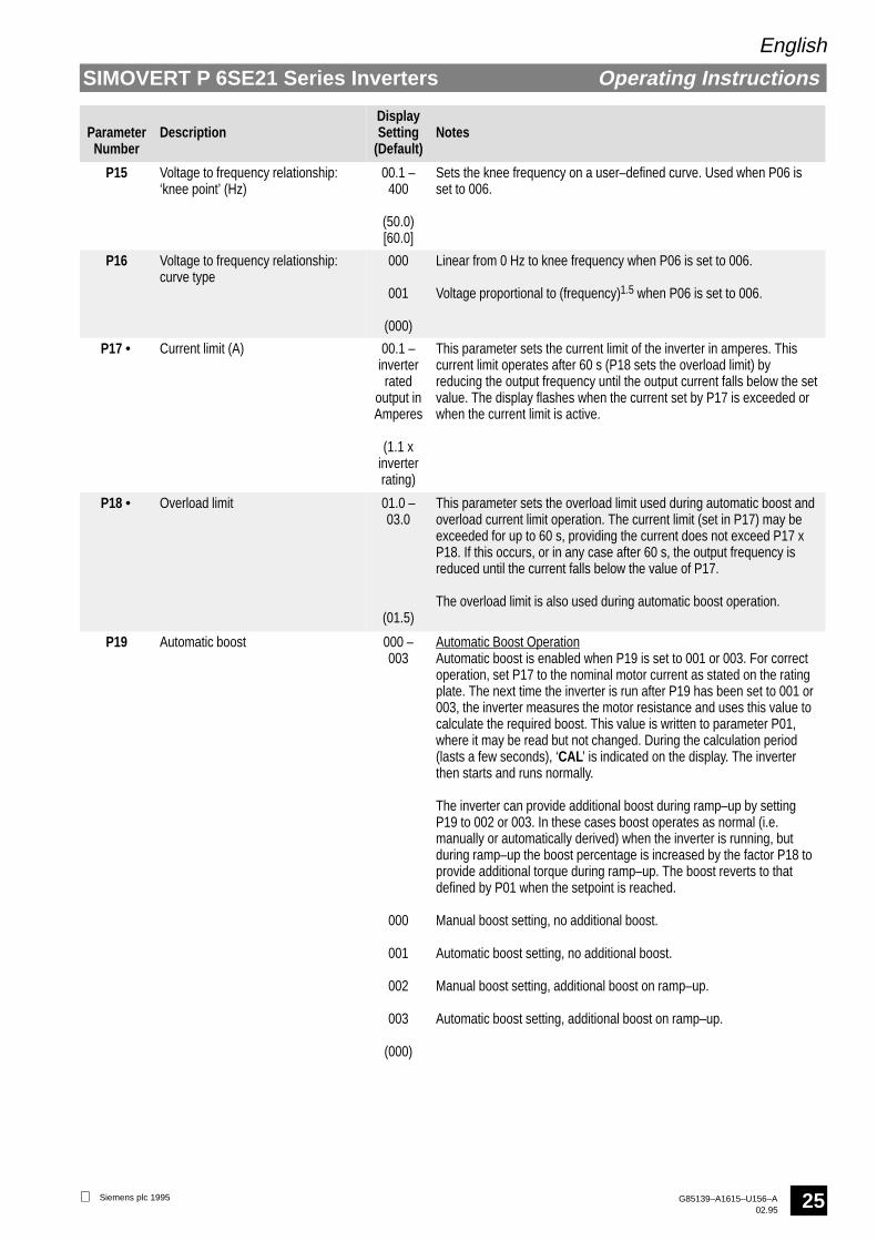
P15 Voltage to frequency relationship:‘knee point’ (Hz)
00.1 –400
(50.0)[60.0]
Sets the knee frequency on a user–defined curve. Used when P06 isset to 006.
P16 Voltage to frequency relationship:curve type
000
001
(000)
Linear from 0 Hz to knee frequency when P06 is set to 006.
Voltage proportional to (frequency)1.5 when P06 is set to 006.
P17 • Current limit (A) 00.1 –inverterrated
output inAmperes
(1.1 xinverterrating)
This parameter sets the current limit of the inverter in amperes. Thiscurrent limit operates after 60 s (P18 sets the overload limit) byreducing the output frequency until the output current falls below the setvalue. The display flashes when the current set by P17 is exceeded orwhen the current limit is active.
P18 • Overload limit 01.0 –03.0
(01.5)
This parameter sets the overload limit used during automatic boost andoverload current limit operation. The current limit (set in P17) may beexceeded for up to 60 s, providing the current does not exceed P17 xP18. If this occurs, or in any case after 60 s, the output frequency isreduced until the current falls below the value of P17.
The overload limit is also used during automatic boost operation.
P19 Automatic boost 000 –003
000
001
002
003
(000)
Automatic Boost OperationAutomatic boost is enabled when P19 is set to 001 or 003. For correctoperation, set P17 to the nominal motor current as stated on the ratingplate. The next time the inverter is run after P19 has been set to 001 or003, the inverter measures the motor resistance and uses this value tocalculate the required boost. This value is written to parameter P01,where it may be read but not changed. During the calculation period(lasts a few seconds), ‘CAL’ is indicated on the display. The inverterthen starts and runs normally.
The inverter can provide additional boost during ramp–up by settingP19 to 002 or 003. In these cases boost operates as normal (i.e.manually or automatically derived) when the inverter is running, butduring ramp–up the boost percentage is increased by the factor P18 toprovide additional torque during ramp–up. The boost reverts to thatdefined by P01 when the setpoint is reached.
Manual boost setting, no additional boost.
Automatic boost setting, no additional boost.
Manual boost setting, additional boost on ramp–up.
Automatic boost setting, additional boost on ramp–up.
SIMOVERT P 6SE21 Series Inverters
English
Operating Instructions
Siemens plc 1995G85139–A1615–U156–A02.95
26
ParameterNumber
DescriptionDisplaySetting
(Default)Notes
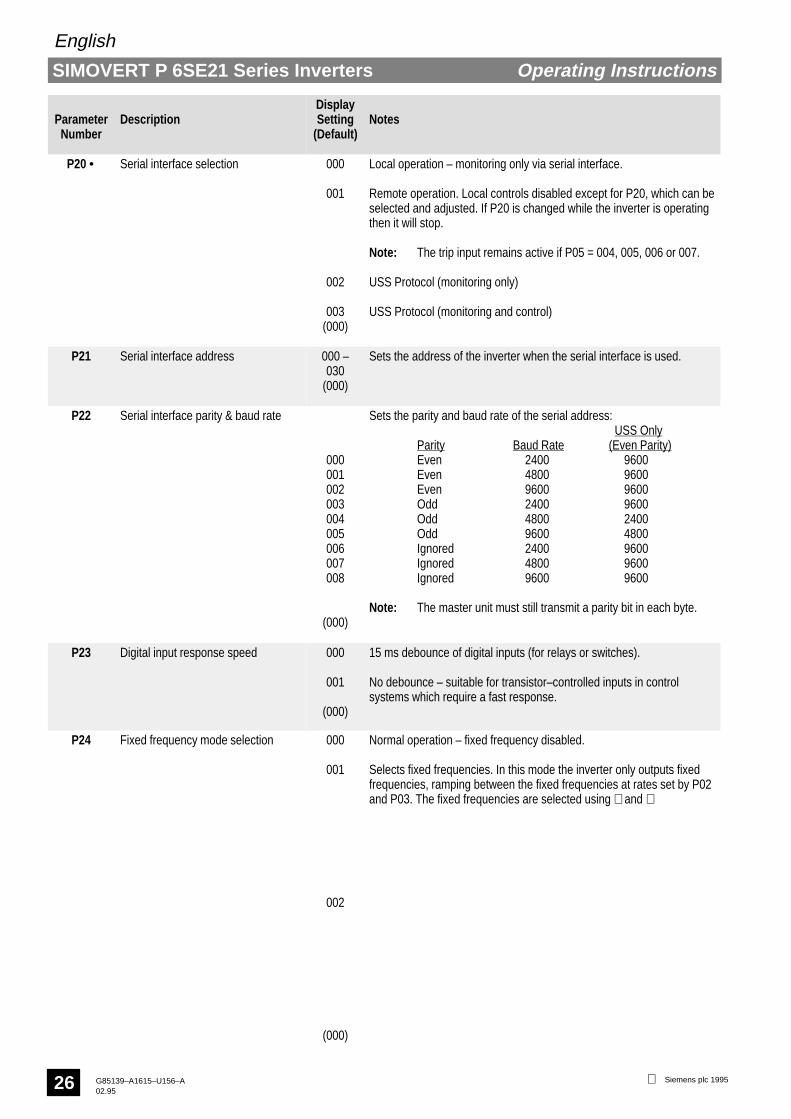
P20 • Serial interface selection 000
001
002
003(000)
Local operation – monitoring only via serial interface.
Remote operation. Local controls disabled except for P20, which can beselected and adjusted. If P20 is changed while the inverter is operatingthen it will stop.
Note: The trip input remains active if P05 = 004, 005, 006 or 007.
USS Protocol (monitoring only)
USS Protocol (monitoring and control)
P21 Serial interface address 000 –030
(000)
Sets the address of the inverter when the serial interface is used.
P22 Serial interface parity & baud rate
000001002003004005006007008
(000)
Sets the parity and baud rate of the serial address: USS Only
Parity Baud Rate (Even Parity)Even 2400 9600Even 4800 9600Even 9600 9600Odd 2400 9600Odd 4800 2400Odd 9600 4800Ignored 2400 9600Ignored 4800 9600Ignored 9600 9600
Note: The master unit must still transmit a parity bit in each byte.
P23 Digital input response speed 000
001
(000)
15 ms debounce of digital inputs (for relays or switches).
No debounce – suitable for transistor–controlled inputs in controlsystems which require a fast response.
P24 Fixed frequency mode selection 000
001
002
(000)
Normal operation – fixed frequency disabled.
Selects fixed frequencies. In this mode the inverter only outputs fixedfrequencies, ramping between the fixed frequencies at rates set by P02and P03. The fixed frequencies are selected using ∧ and ∨ (terminalsX11.17 and X11.18) in accordance with the following table:
Allows three fixed frequencies (P26, P27 & P28) and one analoguesetpoint in accordance with the following table:
Note: 002 is only valid if P04 is set to 000, 001, 002, 007, 008 or009.
Freq1
Freq2
Freq3
Freq4
(1 = 7 – 33 V)(0 = < 7 V)
00
10
01
11
AnalogueFreq
Freq2
Freq3
Freq4
00
01
10
11

SIMOVERT P 6SE21 Series Inverters
English
Operating Instructions
Siemens plc 1995 G85139–A1615–U156–A02.95
27
ParameterNumber
DescriptionDisplaySetting
(Default)Notes
P25 First fixed frequency (Hz) 00.0 –400
(00.0)
Fixed frequency.
P26 Second fixed frequency (Hz) 00.0 –400
(00.0)
Fixed frequency.
P27 Third fixed frequency (Hz) 00.0 –400
(00.0)
Fixed frequency.
P28 Fourth fixed frequency (Hz) 00.0 –400
(00.0)
Fixed frequency.
P29 Skip frequency (Hz) 00.0 –400
(00.0)
This parameter allows a skip frequency to be selected. Operation of theinverter will be inhibited over the range (skip frequency – 2 Hz) to (skipfrequency + 2 Hz). If a frequency in this range is selected, the lower orhigher frequency will be selected and displayed. Note that duringramping the frequency output will ramp continuously and not ‘step’through the skip range.
P30 Tachometer mode
000
001
002
003
004
(000)
This parameter enables the tachometer input and selects thetachometer calculation rate. See section 6 for further details oftachometer applications.
Tachometer input disabled.
Normal feedback.
Feedback control suspended during ramping.
As 001, except output disabled when frequency falls to P07 (minimumfrequency).
As 002, except output disabled when frequency falls to P07 (minimumfrequency).
P31 • Tachometer scale factor 00.0 –999
(50.0)
Frequency at 50 V tacho input. See section 6 for further details.
P32 • Feedback compensation:proportional term (%)
000 –999
(050)
See section 6 for further details.
P33 • Feedback compensation:integral term (%)
000 –250
(000)
See section 6 for further details.
P34 • Feedback compensation:differential term (%)
000 –250
(000)
See section 6 for further details.
P35 • Tachometer slip limit (Hz) 00.0 –20.0
(05.0)
See section 6 for further details.
P36 • Tachometer sample rate 001 –200
(001)
n x 30 ms. See section 6 for further details.

SIMOVERT P 6SE21 Series Inverters
English
Operating Instructions
Siemens plc 1995G85139–A1615–U156–A02.95
28
ParameterNumber
DescriptionDisplaySetting
(Default)Notes
P37 Display tachometer frequencyreading
000 –400
Read only.
P40 Switching frequency select 000
001
002
(002)
19.2 kHz for single phase units.9.6 kHz for three phase units
max. load current for 6SE2108–3AA21 is reduced to 10 Amax. load current for 6SE2133–3AA21 is reduced to 25 Amax. load current for 6SE2142–3AA21 is reduced to 31 A
19.2 kHz for single phase units.19.2 kHz for three phase units except 6SE2133–3AA21 and
6SE2142–3AA21max. load current for 6SE2108–3AA21 is reduced to 8 A
9.6 kHz for 6SE2133–3AA21 and 6SE2142–3AA21max. load current for 6SE2133–3AA21 is reduced to 25 Amax. load current for 6SE2142–3AA21 is reduced to 31 A
19.2 kHz for single phase units.4.8 kHz for three phase units.
Note: Use switching frequencies above the factory settings onlywhen accoustic noise generation is critical. If long motorcables (> 30 m) are being used, set the switching frequencyto the minimum value.
P41 Parameter default values 000
001
(000)
Selects European default values – shown in parentheses ( ).
Selects North American default values – shown in square brackets [ ]where different.
Note: Reading the value of P41 does not change parametersettings. To reinstall factory settings, the value of P41 mustbe changed (e.g. 000 to 001, P, P, 001 to 000).
P42 Auto reset mode 000
001
002
(000)
Auto reset disabled.
Enables auto reset of fault indications. The unit will attempt to reset faultconditions up to five times within one minute. If the fault conditionpersists after one minute the display will show the last fault code.
Running restart.When enabled, the inverter starts up at the setpoint frequency andincreases its output voltage gradually until it reaches its full operatingvalue. To restart automatically in this way following a line voltageinterruption, operate the RUN/STOP signal in level–triggered mode (i.e.P05 set to 001, 003, 006 or 007) and set terminal X11.3 to a voltage >7 V at power–up. This can be achieved by linking between X11.2(+15 V) and X11.3.
Note: If P005 is set to ‘006’ or ‘007’ (PTC active), connect 7 V orgreater to X11.4.
P43 Ramp smoothing (%) 000
001 –100
(000)
Linear ramp up / ramp down.
Ramp rates reduced as frequency approaches the setpoint. Theparameter value corresponds to the percentage of the ramp curve thatis rounded. i.e.:
Note:Total ramp up / rampdown times areextended as thisparameter isincreased.
f
t
100%
100%x
x = % value of P43

SIMOVERT P 6SE21 Series Inverters
English
Operating Instructions
Siemens plc 1995 G85139–A1615–U156–A02.95
29
ParameterNumber
DescriptionDisplaySetting
(Default)Notes
P44 Tachometer interface unit 000
001
002
003
004
(000)
Tachometer interface unit not supported.
Tachometer interface unit Mode 1.
Tachometer interface unit Mode 2.
Tachometer interface unit Mode 3.
Tachometer interface unit Mode 4.
P45 Clear text operator panel language 000
001
English.
German.
P48 Fault code 000 –011
Stores the last recorded fault code.
P49 Hardware type Factory set – cannot be changed.
P50 Software version Factory set – cannot be changed.
P51 Customer–specific variants 000 –255
(000)
Do not adjust.
P52 Current monitor scaling factor (%) 001 –200
(100)
Allows compensation to be made for inaccuracies associated with theuse of long output cables.

SIMOVERT P 6SE21 Series Inverters
English
Operating Instructions
Siemens plc 1995G85139–A1615–U156–A02.95
30
5.4 Fault Indications
In the event of a fault condition arising, the inverter will stop and the display will indicate F, followed by a two–digit code(see Figure 5 below).
Fault Code Cause Corrective Action
Excessive load current
orExcessive link voltage
orLow line voltage(models 6SE21**–3AA21 only).
Ensure rating plate on motor corresponds with inverter rating (see section 2.1).
A low frequency voltage boost may be required to start the motor (refer to section5.3.2, P01).
The characteristic voltage/frequency curve of the inverter may not match thatrequired by the motor (refer to section 5.3.2, P06).
The acceleration time for the motor may be too short (refer to section 5.3.2, P02).
Check whether the motor has stalled or is overloaded.
Check for short–circuits or ground faults on the output leads.
Ensure line voltage is within the limits specified on the inverter rating plate.
The deceleration time of the motor may be too short (refer to section 5.3.2, P03).
Check that the voltage of all three input power phases is within the limits specifiedon the inverter rating plate.
Excessive heatsink temperature. Check that the unit has been installed with at least 100 mm clear space above itfor exhaust air and that the air inlet at the bottom of the unit is not obstructed.
Check that the ambient temperature is below 40oC.
Check that the steady motor current is not above the limit specified on the ratingplate.
Corruption of parameterisation datain the non–volatile memory.
Reset all parameters (see section 5.3). Recalibrate the current monitor byremoving power from the inverter, pressing all three parameterisation buttonssimultaneously while applying power to the inverter. The display will indicate ‘CAL’for several seconds while it recalibrates the monitor circuit.
Faulty operation of theanalogue–to–digital converter.
Excessive tachometer feedbackvoltage.
Check that the analogue input voltage on terminal X11.7 is less than +12 V andgreater than –0.5 V.
If operating in current loop control, check that the current entering control terminalX11.9 is less than 25 mA and greater than –1 mA.
Ensure tachometer output does not exceed 50 V at terminal X11.12.
The minimum frequency parameter(P07) has been set to a highervalue than the maximum frequencyparameter (P08).
Reset parameter P07 or P08.
The fixed frequency parameter(P09) has been set outside theminimum/maximum frequencylimits set by parameters P07 &P08. Note that this fault indicatorwill only be enabled if P04 is set to003.
Reset parameter P07, P08 or P09.
Figure 5: Fault Code Table (Sheet 1 of 2)

SIMOVERT P 6SE21 Series Inverters
English
Operating Instructions
Siemens plc 1995 G85139–A1615–U156–A02.95
31
Fault Code Cause Corrective Action
Control board fault. Disconnect the inverter from the input power supply and then reconnect.
Parameter P25 set abovemaximum frequency P08 or belowminimum frequency P07.
Change parameter P25, P08 or P07.
Parameter P26 set abovemaximum frequency P08 or belowminimum frequency P07.
Change parameter P26, P08 or P07.
Parameter P27 set abovemaximum frequency P08 or belowminimum frequency P07.
Change parameter P27, P08 or P07.
Parameter P28 set abovemaximum frequency P08 or belowminimum frequency P07.
Change parameter P28, P08 or P07.
Inverter externally tripped via X11.4input.
Clear external trip on X11.4 and restart the inverter.
Figure 5: Fault Code Table (Sheet 2 of 2)
If a fault indication has been observed and the corrective action implemented, the inverter can be reset by applying aSTOP (low) signal to the run/stop input (terminal X11.3) followed by a RUN (high) signal to the same input.Alternatively, the incoming mains voltage can be switched off and then switched on again.
5.5 Fault RelayA single pole changeover relay is provided to indicate a fault. It is normally energised when the inverter is powered andoperating or stopped. If a fault condition occurs, the relay will be de–energised. The contacts of the relay are connectedto terminals X11.19 (normally open, de–energised), X11.20 (common) and X11.21 (normally closed, de–energised) onthe control board.
SIMOVERT P 6SE21 Series Inverters
English
Operating Instructions
Siemens plc 1995G85139–A1615–U156–A02.95
32
6. USING CLOSED LOOP SPEED CONTROL
6.1 Introduction
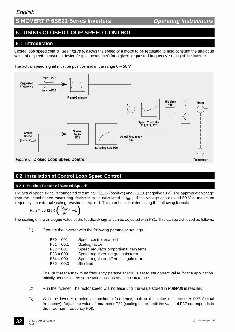
Closed loop speed control (see Figure 6) allows the speed of a motor to be regulated to hold constant the analoguevalue of a speed measuring device (e.g. a tachometer) for a given ‘requested frequency’ setting of the inverter.
The actual speed signal must be positive and in the range 0 – 50 V.
f
tfmax – P08
fmin – P07
Ramp Generator
RequestedFrequency
ScalingActualSpeed Factor
P31
Sampling Rate P36
f
Slip Limit
Speed ControllerP32, P33, P34
P35
Actual FrequencyP37
+
–
Figure 6: Closed Loop Speed Control
Motor
Tachometer
(0 – 50 Vmax)
6.2 Installation of Control Loop Speed Control
6.2.1 Scaling Factor of ‘Actual Speed’
The actual speed signal is connected to terminal X11.12 (positive) and X11.10 (negative / 0 V). The appropriate voltagefrom the actual speed measuring device is to be calculated at fmax. If the voltage can exceed 50 V at maximumfrequency, an external scaling resistor is required. This can be calculated using the following formula:
Rext = 50 kΩ x –1Vmax
50( )The scaling of the analogue value of the feedback signal can be adjusted with P31. This can be achieved as follows:
(1) Operate the inverter with the following parameter settings:
P30 = 001 Speed control enabledP31 = 00.1 Scaling factorP32 = 001 Speed regulator proportional gain termP33 = 000 Speed regulator integral gain termP34 = 000 Speed regulator differential gain termP35 = 00.0 Slip limit
Ensure that the maximum frequency parameter P08 is set to the correct value for the application.Initially set P09 to the same value as P08 and set P04 to 003.
(2) Run the inverter. The motor speed will increase until the value stored in P08/P09 is reached.
(3) With the inverter running at maximum frequency, look at the value of parameter P37 (actualfrequency). Adjust the value of parameter P31 (scaling factor) until the value of P37 corresponds tothe maximum frequency P08.

SIMOVERT P 6SE21 Series Inverters
English
Operating Instructions
Siemens plc 1995 G85139–A1615–U156–A02.95
33
Once steps (1) to (3) have been performed, P04 can be changed to match the requirements of the application.
NoteSpeed control only operates in one direction of rotation – negative values of the actual speed feedback signal onterminal X11.12 are not permitted.
6.2.2 Speed Control Operation
Stop the inverter and adjust the slip limit (P35) to 10.0 (unless the application requires the slip to be limited to a lowervalue). Set the required frequency to a value in the middle of the operating range (i.e. approximately half way betweenthe minimum and maximum frequencies required in operation). Set the inverter to run and increase the setting of P32gradually until the motor speed starts to oscillate. Reduce the value of P32 until a stable speed is obtained.
6.2.3 Speed Control Optimisation
If it is not possible to achieve stable operation with P32 set to a value of greater than 10, there must be excessive noiseon the feedback signal. It may be possible to filter out this noise by increasing the setting of the sampling rate parameter(P36). If this fails then the feedback signal should be shielded and, in extreme cases, smoothed using suitablecapacitors.
Check the performance of the speed regulation. If the speed regulation is satisfactory when the load on the motorchanges then no further adjustments are required. However, the integral term and differential term parameters (P33and P34 respectively) allow further adjustments to be made to the control loop to compensate for delay and/or leadterms in the motor and its associated speed sensor. This can provide better speed regulation in certain systems.
Reducing the value of the proportional gain term will normally give more stable operation but with slightly degradedspeed–holding performance.
The slip limit parameter (P35) can be used to limit the maximum permissible deviation between the instantaneousvalue of actual frequency and the output frequency.
6.2.4 Slip Limit (P35)
The slip limit parameter (P35) allows the difference between the actual frequency (from the tachometer) and theinverter output frequency to be limited to a maximum level. This may be used to prevent motor stalling under overloadconditions.
6.2.5 Sample Rate (P36)
This parameter allows the rate at which the actual frequency value used by the speed regulator is updated to bechanged in 30 ms increments. When P36 is set to 001, the value is updated every 30 ms; when it is set to 002 it isupdated every 60 ms, etc.
Longer sample rates may be required in applications where electrical noise is present on the analogue feedback signalor where the value of the analogue signal only responds slowly to changes in inverter/motor frequency.

SIMOVERT P 6SE21 Series Inverters
English
Operating Instructions
Siemens plc 1995G85139–A1615–U156–A02.95
34
7. QUICK REFERENCE GUIDE
7.1 Connections
Function
0 V Connection+15 VRun ConnectionTripForward / Reverse10 VFrequency Adjust Voltage0 VFrequency Adjust Current0 VFrequency / Current IndicationTachometerJogABP∧∨Fault Indication NOFault Indication CommonFault Indication NC0 V
P
SIMOVERT P
N
L1
1
3
2
5
W
V
U
12
10
11
9
6
7
8
X1 X1
L1
N
PE
Mains
L3
L2
X1
L1
L1L2L3PE
Mains
Motor
Tachometer
Frequency/Output Current Indicator
Essential
Optional
OR
X11
X11
0..10 V
0..20 mA4..20 mA
Frequency setpoint(analogue)
RUN
Forward/Reverse
+
+13Jog
2021
19Fault Indication to
External Alarm17
18
16P
1415
SerialCommsRS485
4Trip
PTC
+
RUN
OR
OR
0 V
R/S
+15 V
M3
Terminal
12345678910111213141516171819202122
Remarks
Apply voltage or connect to +15 V to runNormally closed trip input when P05 = 4, etc.Apply voltage or connect to +15 V to reverse
0 – 20 mA or 4 – 20 mA input
Output for frequency (Fmax) or current (Imax) monitorAnalogue tachometer or sensor inputExternal jog button connection
RS485 serial connection
Push–button connections
Fault relay output
10kTypical frequencycontrol arrangement
1AC 220 – 240 V, 50/60 Hz
3AC 380 – 500 V, 50/60 Hz

SIMOVERT P 6SE21 Series Inverters
English
Operating Instructions
Siemens plc 1995 G85139–A1615–U156–A02.95
35
7.2 Parameter ListParameter Description Value Range Default Settings
[ ] – N. America OnlyP00 Frequency, output current or fault codeP01 Low frequency voltage boost 00.0 – 30.0% 00.0P02 Ramp–up time to maximum frequency 00.0 – 400 s 10.0P03 Ramp–down time from maximum frequency 00.0 – 400 s 10.0P04 Frequency control mode selection 000 – 009 000P05 RUN/STOP mode 000 – 009 000P06 Voltage to frequency curve selection 000 – 006 000 [001]P07 Minimum frequency 00.0 – 399 Hz 00.1P08 Maximum frequency 00.1 – 400 Hz 50.0 [60.0]P09 Digital frequency setpoint adjustment 00.0 – 400 Hz 50.0 [60.0]P10 Analogue frequency setpoint adjustment 080 – 240% 100P11 DC injection braking 00.0 – 20.0% 00.0P12 Jog 00.1 – 400 Hz 05.0P13 Slip compensation 00.0 – 20.0 00.0P14 Display status / Analogue output 000 – 003 000P15 Voltage to frequency relationship: knee point 00.1 – 400 Hz 50.0 [60.0]P16 Voltage to frequency relationship: curve type 000 or 001 000P17 Current limit 00.1 – rated output 1.1 xP18 Overload limit 01.0 – 03.0 01.5P19 Automatic boost 000 – 003 000P20 Serial interface selection 000 – 003 000P21 Serial interface address 000 – 030 000P22 Serial interface parity and baud rate 000 – 008 000P23 Digital input response speed 000 or 001 000P24 Fixed frequency mode selection 000 – 002 000P25 First fixed frequency 00.0 – 400 00.0P26 Second fixed frequency 00.0 – 400 00.0P27 Third fixed frequency 00.0 – 400 00.0P28 Fourth fixed frequency 00.0 – 400 00.0P29 Skip frequency 00.0 – 400 00.0P30 Tachometer mode 000 – 004 000P31 Tachometer scale factor 00.1 – 999 50.0P32 Feedback compensation: proportional term 000 – 999% 050P33 Feedback compensation: integral term 000 – 250% 000P34 Feedback compensation: differential term 000 – 250% 000P35 Tachometer slip limit 00.0 – 20.0 Hz 05.0P36 Tachometer sample rate 001 – 200 001P37 Display tachometer frequency reading 000 – 400 n/aP40 Switching frequency select 000 – 002 002P41 Parameter default values 000 or 001 000 [001]P42 Auto reset mode 000 – 002 000P43 Ramp smoothing 000 – 100% 000P44 Tachometer Interface Unit 000 – 004 000P45 Clear Text Operator Panel language 000 or 001 n/aP48 Fault code 000 – 011 n/aP49 Hardware typeP50 Software versionP51 Customer–specific variants 000 – 255 000P52 Current monitor scaling factor 001 – 200% 100
7.3 Fault CodesCode MeaningF00 Excessive load current or excessive link voltage. Low line voltage (6SE21**–3AA21 only).F01 Excessive heatsink temperature.F02 Corruption of parameterisation data in the non–volatile memory.F03 Faulty operation of A–D converter or excessive tachometer feedback voltage.F04 P07 set to a higher value than P08.F05 P09 outside the limits set by P07 and P08.F06 Fault on control board.F07 Value of P25 > P08 setting or < P07 setting.F08 Value of P26 > P08 setting or < P07 setting.F09 Value of P27 > P08 setting or < P07 setting.F10 Value of P28 > P08 setting or < P07 setting.F11 Inverter tripped externally via X11.4 input.

SIMOVERT P 6SE21 Series Inverters
English
Operating Instructions
Siemens plc 1995G85139–A1615–U156–A02.95
36
This page is intentionally blank