english deutsch español français easy aimer · i mmmmm table of contents table of contents...
TRANSCRIPT

Instruction Manual February 2005
MODELS 2 · 304easy aimer
English
Deutsch
Español
Français

© Siemens Milltronics Process Instruments Inc. 2004
Safety Guidelines: Warning notices must be observed to ensure personal safety as well as that of
others, and to protect the product and the connected equipment. These warning notices are
accompanied by a clarification of the level of caution to be observed.
Qualified Personnel: This device/system may only be set up and operated in conjunction with this
manual. Qualified personnel are only authorized to install and operate this equipment in accordance with
established safety practices and standards.
Unit Repair and Excluded Liability:
• The user is responsible for all changes and repairs made to the device by the user or the user’s
agent.
• All new components are to be provided by Siemens Milltronics Process Instruments Inc.
• Restrict repair to faulty components only.
• Do not reuse faulty components.
Warning: This product can only function properly and safely if it is correctly transported, stored,
installed, set up, operated, and maintained.
Note: Always use product in accordance with specifications.
Copyright Siemens Milltronics Process Instruments Inc. 2004. All Rights Reserved
Disclaimer of Liability
This document is available in bound version and in
electronic version. We encourage users to purchase
authorized bound manuals, or to view electronic versions
as designed and authored by Siemens Milltronics Process
Instruments Inc. Siemens Milltronics Process Instruments
Inc. will not be responsible for the contents of partial or
whole reproductions of either bound or electronic
versions.
While we have verified the contents of this
manual for agreement with the
instrumentation described, variations
remain possible. Thus we cannot
guarantee full agreement. The contents of
this manual are regularly reviewed and
corrections are included in subsequent
editions. We welcome all suggestions for
improvement.
Technical data subject to change.
MILLTRONICS®is a registered trademark of Siemens Milltronics Process Instruments Inc.
Contact SMPI Technical Publications at the following address:
Technical Publications
Siemens Milltronics Process Instruments Inc.
1954 Technology Drive, P.O. Box 4225
Peterborough, Ontario, Canada, K9J 7B1
Email: [email protected]
• For a selection of Siemens Milltronics level measurement manuals, go to:
www. siemens.com/processautomation. Under Process Instrumentation, select Level
Measurement and then go to the manual archive listed under the product family.
• For a selection of Siemens Milltronics weighing manuals, go to:
www. siemens.com/processautomation. Under Weighing Technology, select Continuous
Weighing Systems and then go to the manual archive listed under the product family.
i
mm
mm
m
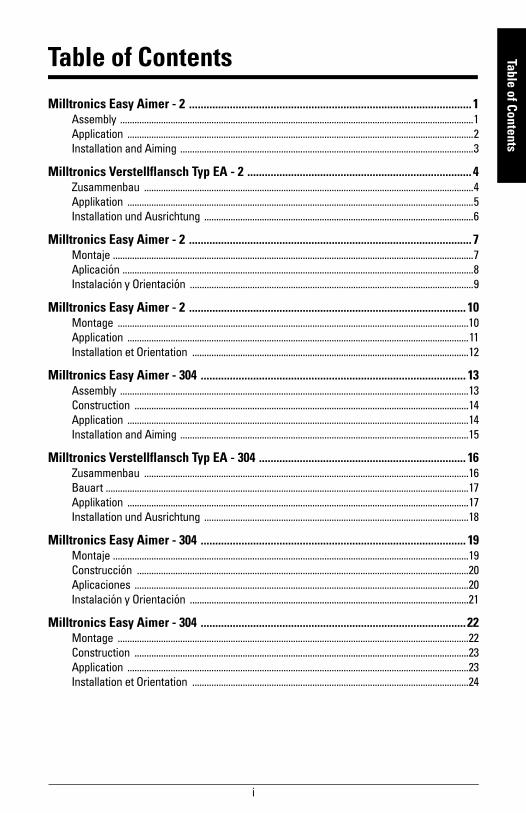
Table of Contents
Table of Contents
Milltronics Easy Aimer - 2 ................................................................................................. 1Assembly ...................................................................................................................................................1
Application ................................................................................................................................................2
Installation and Aiming ..........................................................................................................................3
Milltronics Verstellflansch Typ EA - 2 ............................................................................. 4Zusammenbau .........................................................................................................................................4
Applikation ................................................................................................................................................5
Installation und Ausrichtung ................................................................................................................6
Milltronics Easy Aimer - 2 ................................................................................................. 7Montaje ......................................................................................................................................................7
Aplicación ..................................................................................................................................................8
Instalación y Orientación ......................................................................................................................9
Milltronics Easy Aimer - 2 ............................................................................................... 10Montage ..................................................................................................................................................10
Application ..............................................................................................................................................11
Installation et Orientation ...................................................................................................................12
Milltronics Easy Aimer - 304 ........................................................................................... 13Assembly .................................................................................................................................................13
Construction ...........................................................................................................................................14
Application ..............................................................................................................................................14
Installation and Aiming ........................................................................................................................15
Milltronics Verstellflansch Typ EA - 304 ....................................................................... 16Zusammenbau .......................................................................................................................................16
Bauart .......................................................................................................................................................17
Applikation ..............................................................................................................................................17
Installation und Ausrichtung ..............................................................................................................18
Milltronics Easy Aimer - 304 ........................................................................................... 19Montaje ....................................................................................................................................................19
Construcción ..........................................................................................................................................20
Aplicaciones ...........................................................................................................................................20
Instalación y Orientación ....................................................................................................................21
Milltronics Easy Aimer - 304 ...........................................................................................22Montage ..................................................................................................................................................22
Construction ...........................................................................................................................................23
Application ..............................................................................................................................................23
Installation et Orientation ...................................................................................................................24

ii
mm
mm
m
Tabl
e of
Con
tent
s
7ML19985HG62 Easy Aimer 2 – INSTRUCTION MANUAL Page 1
mm
mm
m
EA 2 – English
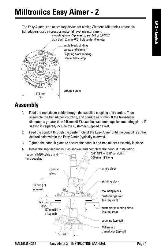
Milltronics Easy Aimer - 2
The Easy Aimer is an accessory device for aiming Siemens Milltronics ultrasonic
transducers used in process material level measurement.
Assembly1. Feed the transducer cable through the supplied coupling and conduit. Then
assemble the transducer, coupling, and conduit as shown. If the transducer
diameter is greater than 148 mm (5.8"), use the customer supplied mounting plate. If
sealing is required, include the customer supplied gasket.
2. Feed the conduit through the center hole of the Easy Aimer until the conduit is at the
desired point within the Easy Aimer (typically midway).
3. Tighten the conduit gland to secure the conduit and transducer assembly in place.
4. Install the supplied locknut as shown, and complete the conduit installation.
EASY
AIMER II
MILLTRONICS
mounting hole - 3 places, to suit M8 or 3/8”, 120°
apart on 157 mm (6.2") bolt center diameter
angle block binding
screw and clamp
sighting block binding
screw and clamp
ground screw178 mm
(7")
3/4” NPT or BSP conduit x
300 mm (12") long
mounting block
customer gasket
(as required)
customer mounting plate
(as required)
coupling (typical)
Milltronics
transducer (typical)20°
76 mm (3")
nominal
127 mm (5")
ø (typical)
12.7 mm
(0.5")
sighting block
conduit
gland
angle block
optional M20 cable gland
and coupling
Page 2 Easy Aimer 2 – INSTRUCTION MANUAL 7ML19985HG62
mm
mm
m
EA 2
– E
nglis
h
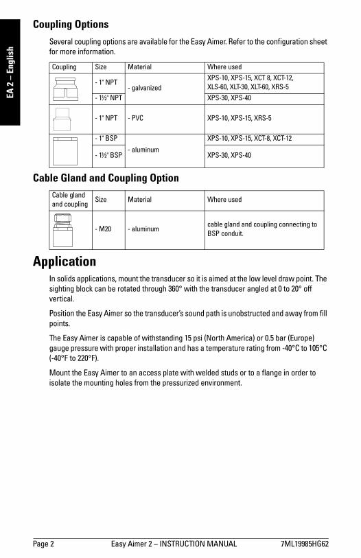
Coupling OptionsSeveral coupling options are available for the Easy Aimer. Refer to the configuration sheet
for more information.
Cable Gland and Coupling Option
ApplicationIn solids applications, mount the transducer so it is aimed at the low level draw point. The
sighting block can be rotated through 360° with the transducer angled at 0 to 20° off
vertical.
Position the Easy Aimer so the transducer’s sound path is unobstructed and away from fill
points.
The Easy Aimer is capable of withstanding 15 psi (North America) or 0.5 bar (Europe)
gauge pressure with proper installation and has a temperature rating from -40°C to 105°C
(-40°F to 220°F).
Mount the Easy Aimer to an access plate with welded studs or to a flange in order to
isolate the mounting holes from the pressurized environment.
Coupling Size Material Where used
- 1" NPT- galvanized
XPS-10, XPS-15, XCT 8, XCT-12,
XLS-60, XLT-30, XLT-60, XRS-5
- 1½" NPT XPS-30, XPS-40
- 1" NPT - PVC XPS-10, XPS-15, XRS-5
- 1" BSP
- aluminum
XPS-10, XPS-15, XCT-8, XCT-12
- 1½" BSP XPS-30, XPS-40
Cable gland
and couplingSize Material Where used
- M20 - aluminumcable gland and coupling connecting to
BSP conduit.

7ML19985HG62 Easy Aimer 2 – INSTRUCTION MANUAL Page 3
mm
mm
m
EA 2 – English
Installation and Aiming1. Install the Easy Aimer and transducer assembly by bolting the mounting block
directly to the bin or via a mounting plate.
2. Leaving the sighting block binding screws fastened and loosen the angle block
binding screws. Rotate the angle block until the transducer is pointing at the desired
angle. Refasten angle block binding screws.
3. Loosen the sighting block binding screws and rotate sighting block until the
transducer is pointing in the desired direction. Sighting reference graduations on
the mounting block are 30° apart. Refasten sighting block binding screws.
mounting plate
and hardware
(customer
supplied)
sighting adjustment
angle adjustment
conduit gland
tighten to 95 N-m
(70 ft lb) of torque
mounting
hardware,
3 places, tighten
to 8 N-m
(6 ft lb) of torque
basic installation
mounting plate with
welded studs
(customer supplied)
recommended gasket
thickness 1.5-1.8 mm
(0.06"-0.07”)
(customer supplied)
block binding
screws, 6 places,
tighten to 3 N-m
(25 in lb) of torque
sealed installation
Seite 4 Verstellflansch Typ EA - 2 – BETRIEBSANLEITUNG 7ML19985HG62
mm
mm
m
EA 2
– D
euts
ch
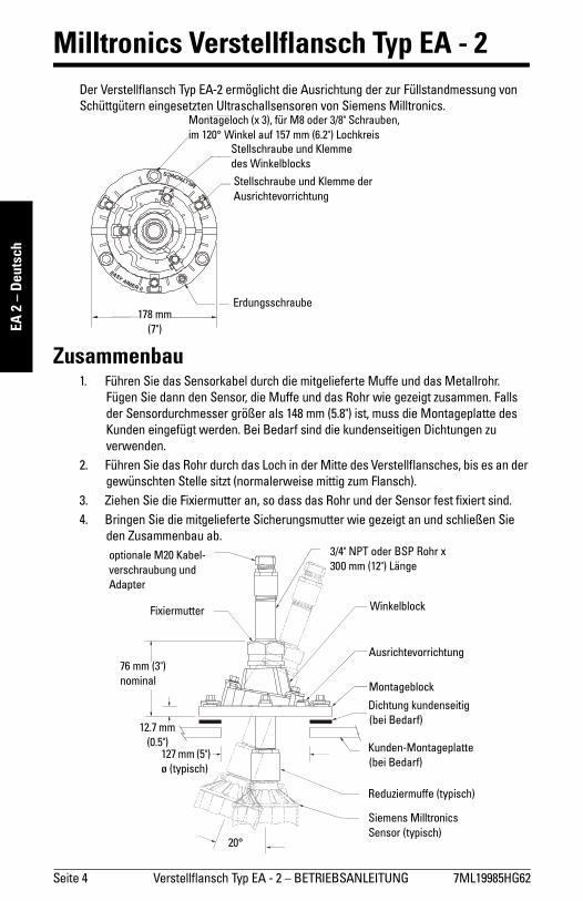
Milltronics Verstellflansch Typ EA - 2Der Verstellflansch Typ EA-2 ermöglicht die Ausrichtung der zur Füllstandmessung von
Schüttgütern eingesetzten Ultraschallsensoren von Siemens Milltronics.
Zusammenbau1. Führen Sie das Sensorkabel durch die mitgelieferte Muffe und das Metallrohr.
Fügen Sie dann den Sensor, die Muffe und das Rohr wie gezeigt zusammen. Falls
der Sensordurchmesser größer als 148 mm (5.8") ist, muss die Montageplatte des
Kunden eingefügt werden. Bei Bedarf sind die kundenseitigen Dichtungen zu
verwenden.
2. Führen Sie das Rohr durch das Loch in der Mitte des Verstellflansches, bis es an der
gewünschten Stelle sitzt (normalerweise mittig zum Flansch).
3. Ziehen Sie die Fixiermutter an, so dass das Rohr und der Sensor fest fixiert sind.
4. Bringen Sie die mitgelieferte Sicherungsmutter wie gezeigt an und schließen Sie
den Zusammenbau ab.
EASY
AIMER II
MILLTRONICS
Montageloch (x 3), für M8 oder 3/8" Schrauben,
im 120° Winkel auf 157 mm (6.2") Lochkreis
Stellschraube und Klemme
des Winkelblocks
Stellschraube und Klemme der
Ausrichtevorrichtung
Erdungsschraube178 mm
(7")
3/4" NPT oder BSP Rohr x
300 mm (12") Länge
Montageblock
Dichtung kundenseitig
(bei Bedarf)
Kunden-Montageplatte
(bei Bedarf)
Reduziermuffe (typisch)
Siemens Milltronics
Sensor (typisch)20°
76 mm (3")
nominal
127 mm (5")
ø (typisch)
12.7 mm
(0.5")
Ausrichtevorrichtung
Fixiermutter Winkelblock
optionale M20 Kabel-
verschraubung und
Adapter

7ML19985HG62 Verstellflansch Typ EA - 2 – BETRIEBSANLEITUNG Seite 5
mm
mm
m
EA 2 –Deutsch
Optionen ReduziermuffeFür die Reduziermuffe des Verstellflansches stehen mehrere Optionen zur Verfügung.
Weitere Angaben finden Sie auf dem Konfigurationsblatt.
Option Kabelverschraubung und Adapter
ApplikationBei Applikationen mit Schüttgütern ist der Ultraschallsensor im Allgemeinen auf den
Abzugspunkt im Behälter auszurichten. Der Drehblock lässt sich um 360° drehen, wobei
die Sensorneigung 0 bis 20° von der Vertikalen betragen kann.
Der Verstellflansch muss so montiert werden, dass der Schallkegel von der Befüllung
entfernt ist und nicht durch interne Einbauten behindert wird.
Bei korrekter Installation ist der Verstellflansch Typ EA-2 bis 0,5 bar (Europa) oder 15 psi
(Nordamerika) druckbeständig. Der zugelassene Temperaturbereich beträgt -40°C bis
105°C (-40°F bis 220°F).
Die Montage erfolgt über eine Montageplatte mit angeschweißtem Gewindebolzen oder
einen Flansch, um die Montagebohrungen von der unter Druck stehenden Umgebung zu
isolieren.
Reduziermuffe Größe Material Verwendung mit
- 1" NPT- verzinkt
XPS-10, XPS-15, XCT 8, XCT-12,
XLS-60, XLT-30, XLT-60, XRS-5
- 1½" NPT XPS-30, XPS-40
- 1" NPT - PVC XPS-10, XPS-15, XRS-5
- 1" BSP
- Aluminium
XPS-10, XPS-15, XCT-8, XCT-12
- 1½" BSP XPS-30, XPS-40
Kabelverschraubung
und AdapterGröße Material Verwendung mit
- M20 - AluminiumKabelverschraubung und Adapter mit
Anschluss an BSP Rohr
Seite 6 Verstellflansch Typ EA - 2 – BETRIEBSANLEITUNG 7ML19985HG62
mm
mm
m
EA 2
– D
euts
ch
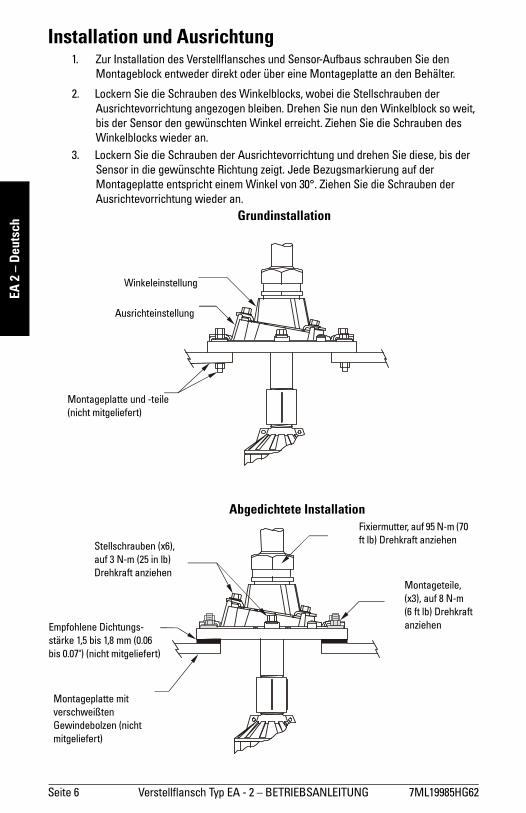
Installation und Ausrichtung 1. Zur Installation des Verstellflansches und Sensor-Aufbaus schrauben Sie den
Montageblock entweder direkt oder über eine Montageplatte an den Behälter.
2. Lockern Sie die Schrauben des Winkelblocks, wobei die Stellschrauben der
Ausrichtevorrichtung angezogen bleiben. Drehen Sie nun den Winkelblock so weit,
bis der Sensor den gewünschten Winkel erreicht. Ziehen Sie die Schrauben des
Winkelblocks wieder an.
3. Lockern Sie die Schrauben der Ausrichtevorrichtung und drehen Sie diese, bis der
Sensor in die gewünschte Richtung zeigt. Jede Bezugsmarkierung auf der
Montageplatte entspricht einem Winkel von 30°. Ziehen Sie die Schrauben der
Ausrichtevorrichtung wieder an.
Montageplatte und -teile
(nicht mitgeliefert)
Ausrichteinstellung
Winkeleinstellung
Fixiermutter, auf 95 N-m (70
ft lb) Drehkraft anziehen
Montageteile,
(x3), auf 8 N-m
(6 ft lb) Drehkraft
anziehen
Grundinstallation
Montageplatte mit
verschweißten
Gewindebolzen (nicht
mitgeliefert)
Empfohlene Dichtungs-
stärke 1,5 bis 1,8 mm (0.06
bis 0.07") (nicht mitgeliefert)
Stellschrauben (x6),
auf 3 N-m (25 in lb)
Drehkraft anziehen
Abgedichtete Installation
7ML19985HG62 Easy Aimer 2 – INSTRUCCIONES DE USO Page 7
mm
mm
m
EA 2 – Español
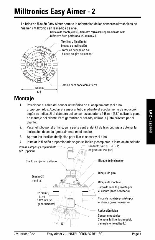
Milltronics Easy Aimer - 2La brida de fijación Easy Aimer permite la orientación de los sensores ultrasónicos de
Siemens Milltronics en la medida de nivel.
Montaje1. Posicionar el cable del sensor ultrasónico en el acoplamiento y el tubo
proporcionados. Acoplar el sensor al tubo mediante el acoplamiento de reducción
según se indica. Si el diámetro del sensor es superior a 148 mm (5,8") utilizar la placa
de montaje del cliente. Para garantizar el sellado, utilizar la junta provista por el
cliente.
2. Pasar el tubo por el orificio, en la parte central del kit de fijación, hasta obtener la
inclinación deseada (generalmente en el medio).
3. Apretar los tornillos de fijación para fijar el sensor y el tubo.
4. Instalar la fijación proporcionada según se indica y completar la instalación del tubo.
EASY
AIMER II
MILLTRONICS
Orificio de montaje (x 3), diámetro M8 ó 3/8”, separación de 120°
Diámetro área perforada 157 mm (6,2")
Tornillos y fijación del
bloque de inclinación
Tornillos de fijación del
bloque de giro del sensor
Tornillo para conexión a tierra178 mm
(7")
Conducto 3/4” NPT ó BSP,
longitud 300 mm (12")
Bloque de montaje
Junta de sellado provista por
el cliente (si es necesario)
Placa de montaje provista por
el cliente (si es necesario)
Reducción típica
Sensor ultrasónico
Siemens Milltronics (modelo
generalmente utilizado)20°
76 mm (3")
nominal
ø 127 mm (5")
(generalmente)
12.7 mm
(0,5")
Bloque de giro
Cuello de fijación del tubo Bloque de inclinación
Prensa estopas y acoplamiento
M20 (opción)
Page 8 Easy Aimer 2 – INSTRUCCIONES DE USO 7ML19985HG62
mm
mm
m
EA 2
– E
spañ
ol
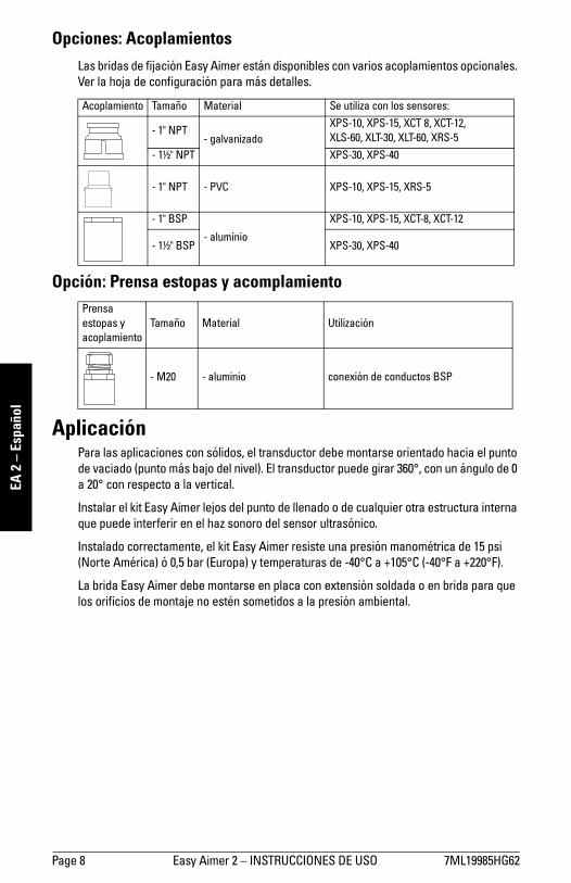
Opciones: AcoplamientosLas bridas de fijación Easy Aimer están disponibles con varios acoplamientos opcionales. Ver la hoja de configuración para más detalles.
Opción: Prensa estopas y acomplamiento
AplicaciónPara las aplicaciones con sólidos, el transductor debe montarse orientado hacia el punto
de vaciado (punto más bajo del nivel). El transductor puede girar 360°, con un ángulo de 0 a 20° con respecto a la vertical.
Instalar el kit Easy Aimer lejos del punto de llenado o de cualquier otra estructura interna que puede interferir en el haz sonoro del sensor ultrasónico.
Instalado correctamente, el kit Easy Aimer resiste una presión manométrica de 15 psi (Norte América) ó 0,5 bar (Europa) y temperaturas de -40°C a +105°C (-40°F a +220°F).
La brida Easy Aimer debe montarse en placa con extensión soldada o en brida para que los orificios de montaje no estén sometidos a la presión ambiental.
Acoplamiento Tamaño Material Se utiliza con los sensores:
- 1" NPT- galvanizado
XPS-10, XPS-15, XCT 8, XCT-12,
XLS-60, XLT-30, XLT-60, XRS-5
- 1½" NPT XPS-30, XPS-40
- 1" NPT - PVC XPS-10, XPS-15, XRS-5
- 1" BSP
- aluminio
XPS-10, XPS-15, XCT-8, XCT-12
- 1½" BSP XPS-30, XPS-40
Prensa
estopas y
acoplamiento
Tamaño Material Utilización
- M20 - aluminio conexión de conductos BSP

7ML19985HG62 Easy Aimer 2 – INSTRUCCIONES DE USO Page 9
mm
mm
m
EA 2 – Español
Instalación y Orientación1. Instalar el kit Easy Aimer y el sensor utrasónico atornillando directamente el bloque
de montaje o una placa de montaje en el depósito.
2. Aflojar los tornillos del bloque de inclinación sin desatornillar los tornillos del bloque
de giro. Girar el bloque de hasta obtener el ángulo de inclinación deseado. Apretar los tornillos del bloque de inclinación.
3. Aflojar los tornillos del bloque de giro y girar el bloque hasta que el sensor apunte en la dirección deseada. Las graduaciones de referencia en el bloque de montaje son de 30°. Apretar los tornillos de sujeción para fijar la orientación del sensor.
Placa y material
de montaje
(provistos por el
cliente)
Ajuste de la dirección
Ajuste del ángulo
Cuello de fijación,
apretar a máx.
95 N-m (70 ft lb)
Material de
montaje (x 3),
apretar a máx.
8 N-m (6 ft lb)
Instalación básica
Placa de montaje, con
extensión soldada
(provista por el cliente)
Espesor recomendado
de la junta de sellado
(provista por el cliente)
1,5-1,8 mm (0,06"-0,07”)
Tornillo de fijación (x 6).
Apretar a máx. 3 N-m
(25 in lb)
Instalación hermética
Page 10 Easy Aimer 2 – INSTRUCTIONS D’UTILISATION 7ML19985HG62
mm
mm
m
EA 2
– F
ranç
ais
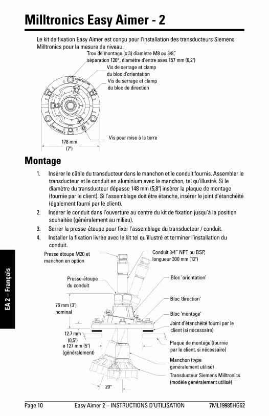
Milltronics Easy Aimer - 2Le kit de fixation Easy Aimer est conçu pour l’installation des transducteurs Siemens Milltronics pour la mesure de niveau.
Montage1. Insérer le câble du transducteur dans le manchon et le conduit fournis. Assembler le
transducteur et le conduit en aluminium avec le manchon, tel qu’illustré. Si le diamètre du transducteur dépasse 148 mm (5,8") insérer la plaque de montage
(fournie par le client). Si l’assemblage doit être étanche, insérer le joint d’étanchéité (également fourni par le client).
2. Insérer le conduit dans l’ouverture au centre du kit de fixation jusqu’à la position souhaitée (généralement au milieu).
3. Serrer la presse-étoupe pour fixer l’assemblage du transducteur / conduit.
4. Installer la fixation livrée avec le kit tel qu’illustré et terminer l’installation du
conduit.
EASY
AIMER II
MILLTRONICS
Trou de montage (x 3) diamètre M8 ou 3/8”,
séparation 120°, diamètre d’entre axes 157 mm (6,2")
Vis de serrage et clamp
du bloc d’orientation
Vis de serrage et clamp
du bloc de direction
Vis pour mise à la terre178 mm
(7")
Conduit 3/4” NPT ou BSP,
longueur 300 mm (12")
Bloc ’montage’
Joint d’étanchéité fourni par le
client (si nécessaire)
Plaque de montage (fournie
par le client, si nécessaire)
Manchon (type
généralement utilisé)
Transducteur Siemens Milltronics
(modèle généralement utilisé)20°
76 mm (3")
nominal
ø 127 mm (5")
(généralement)
12.7 mm
(0,5")
Bloc ’direction’
Presse-étoupe
du conduit
Bloc ’orientation’
Presse étoupe M20 et
manchon en option
7ML19985HG62 Easy Aimer 2 – INSTRUCTIONS D’UTILISATION Page 11
mm
mm
m
EA 2 – Français
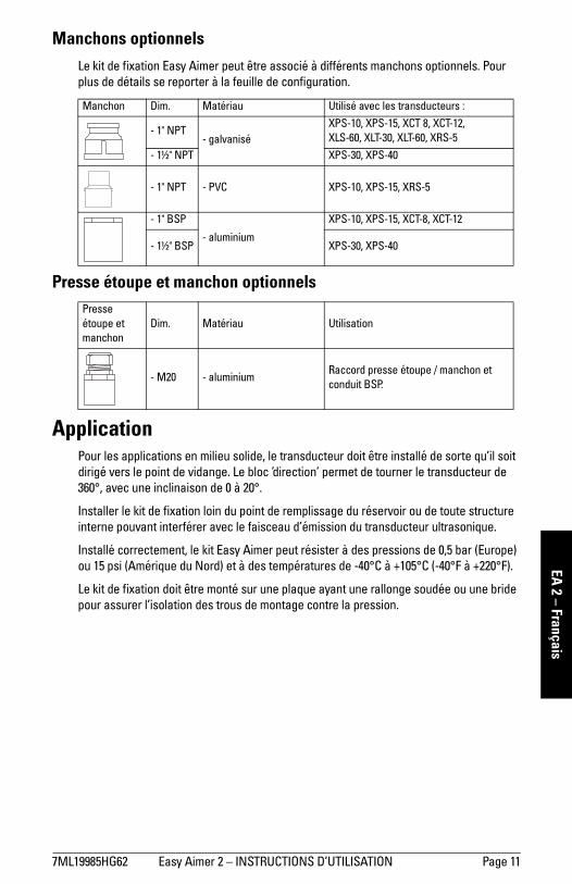
Manchons optionnelsLe kit de fixation Easy Aimer peut être associé à différents manchons optionnels. Pour plus de détails se reporter à la feuille de configuration.
Presse étoupe et manchon optionnels
ApplicationPour les applications en milieu solide, le transducteur doit être installé de sorte qu’il soit dirigé vers le point de vidange. Le bloc ’direction’ permet de tourner le transducteur de 360°, avec une inclinaison de 0 à 20°.
Installer le kit de fixation loin du point de remplissage du réservoir ou de toute structure interne pouvant interférer avec le faisceau d’émission du transducteur ultrasonique.
Installé correctement, le kit Easy Aimer peut résister à des pressions de 0,5 bar (Europe) ou 15 psi (Amérique du Nord) et à des températures de -40°C à +105°C (-40°F à +220°F).
Le kit de fixation doit être monté sur une plaque ayant une rallonge soudée ou une bride pour assurer l’isolation des trous de montage contre la pression.
Manchon Dim. Matériau Utilisé avec les transducteurs :
- 1" NPT- galvanisé
XPS-10, XPS-15, XCT 8, XCT-12,
XLS-60, XLT-30, XLT-60, XRS-5
- 1½" NPT XPS-30, XPS-40
- 1" NPT - PVC XPS-10, XPS-15, XRS-5
- 1" BSP
- aluminium
XPS-10, XPS-15, XCT-8, XCT-12
- 1½" BSP XPS-30, XPS-40
Presse
étoupe et
manchon
Dim. Matériau Utilisation
- M20 - aluminiumRaccord presse étoupe / manchon et
conduit BSP.

Page 12 Easy Aimer 2 – INSTRUCTIONS D’UTILISATION 7ML19985HG62
mm
mm
m
EA 2
– F
ranç
ais
Installation et Orientation1. Pour installer l’assemblage kit Easy Aimer / transducteur, boulonner le bloc
’montage’ directement sur le silo, ou utiliser une plaque de montage.
2. Sans serrer les vis du bloc ’direction’, déserrer les vis du bloc ’orientation’. Pivoter le bloc orientation jusqu’à atteindre la position souhaitée pour le transducteur. Serrer les vis de fixation du bloc ’orientation’ du transducteur.
3. Desserrer les vis du bloc ’direction’ et tourner le bloc pour orienter le transducteur vers le point souhaité. Le kit comporte des graduations sur le bloc ’montage’.
Chaque graduation correspond à un angle de 30°. Serrer les vis de fixation du bloc ’direction’.
Plaque et matériel de
montage (fournis par
le client)
Réglage de la direction]
Réglage de l’angle
Presse-étoupe,
couple recommandé
95 N-m (70 ft lb)
Matériel de montage
(x 3), couple
recommandé
8 N-m (6 ft lb)
Installation de base
Plaque de montage
avec rallonge soudée
(fournie par le client)
Epaisseur recommandée
pour le joint d’étanchéité
1,5-1,8 mm (0,06"-0,07”)
Vis de fixation du bloc (x 6).
Couple recommandé
3 N-m (25 in lb)
Installation hermétique
7ML19985HG62 Easy Aimer 304 – INSTRUCTION MANUAL Page 13
mm
mm
m
EA 304 – English
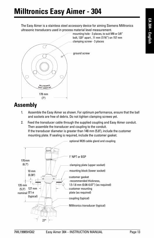
Milltronics Easy Aimer - 304
The Easy Aimer is a stainless steel accessory device for aiming Siemens Milltronics
ultrasonic transducers used in process material level measurement.
Assembly1. Assemble the Easy Aimer as shown. For optimum performance, ensure that the ball
and sockets are free of debris. Do not tighten clamping screws yet.
2. Feed the transducer cable through the supplied coupling and Easy Aimer conduit. Then assemble the transducer and coupling to the conduit.
If the transducer diameter is greater than 148 mm (5.8"), include the customer mounting plate. If sealing is required, include the customer gasket.
mounting hole - 3 places, to suit M8 or 3/8”
bolt, 120° apart , 11 mm (7/16”) on 157 mm
clamping screw - 3 places
ground screw
178 mm
(7")
1" NPT or BSP
clamping plate (upper socket)
mounting block (lower socket)
customer gasket
-recommended thickness,
1.5-1.8 mm (0.06-0.07”) (as required)
customer mounting
plate (as required)
coupling (typical)
Milltronics transducer (typical)
27°
135 mm
(5.3")
nominal
127 mm
(5") ø
(typical)
10 mm
(0.38")
170 mm
(6.7")
optional M20 cable gland and coupling
Page 14 Easy Aimer 304 – INSTRUCTION MANUAL 7ML19985HG62
mm
mm
m
EA 3
04 –
Eng
lish
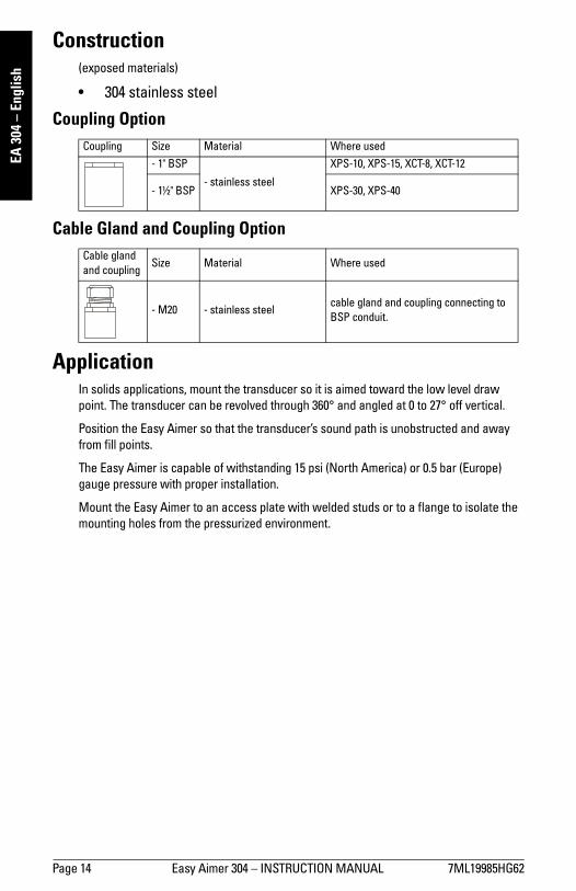
Construction(exposed materials)
• 304 stainless steel
Coupling Option
Cable Gland and Coupling Option
ApplicationIn solids applications, mount the transducer so it is aimed toward the low level draw
point. The transducer can be revolved through 360° and angled at 0 to 27° off vertical.
Position the Easy Aimer so that the transducer’s sound path is unobstructed and away
from fill points.
The Easy Aimer is capable of withstanding 15 psi (North America) or 0.5 bar (Europe)
gauge pressure with proper installation.
Mount the Easy Aimer to an access plate with welded studs or to a flange to isolate the
mounting holes from the pressurized environment.
Coupling Size Material Where used
- 1" BSP
- stainless steel
XPS-10, XPS-15, XCT-8, XCT-12
- 1½" BSP XPS-30, XPS-40
Cable gland
and couplingSize Material Where used
- M20 - stainless steelcable gland and coupling connecting to
BSP conduit.
7ML19985HG62 Easy Aimer 304 – INSTRUCTION MANUAL Page 15
mm
mm
m
EA 304 – English
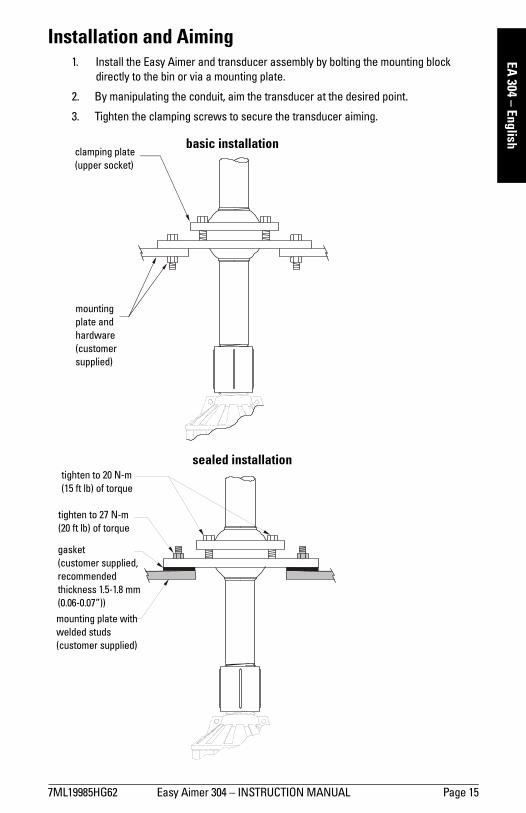
Installation and Aiming1. Install the Easy Aimer and transducer assembly by bolting the mounting block
directly to the bin or via a mounting plate.
2. By manipulating the conduit, aim the transducer at the desired point.
3. Tighten the clamping screws to secure the transducer aiming.
clamping plate
(upper socket)
mounting
plate and
hardware
(customer
supplied)
mounting plate with
welded studs
(customer supplied)
gasket
(customer supplied,
recommended
thickness 1.5-1.8 mm
(0.06-0.07”))
tighten to 27 N-m
(20 ft lb) of torque
tighten to 20 N-m
(15 ft lb) of torque
basic installation
sealed installation
Seite 16 Verstellflansch Typ EA - 304 – BETRIEBSANLEITUNG 7ML19985HG62
mm
mm
m
EA 3
04 –
Deu
tsch
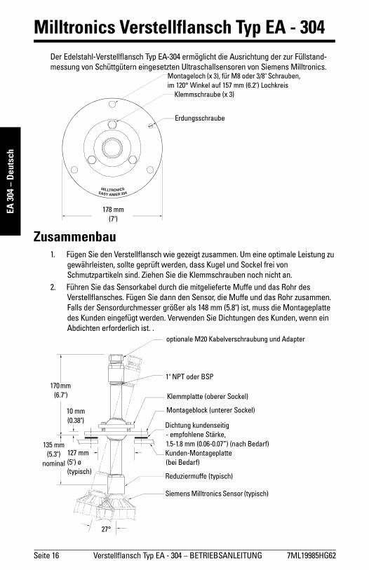
Milltronics Verstellflansch Typ EA - 304Der Edelstahl-Verstellflansch Typ EA-304 ermöglicht die Ausrichtung der zur Füllstand-messung von Schüttgütern eingesetzten Ultraschallsensoren von Siemens Milltronics.
Zusammenbau1. Fügen Sie den Verstellflansch wie gezeigt zusammen. Um eine optimale Leistung zu
gewährleisten, sollte geprüft werden, dass Kugel und Sockel frei von Schmutzpartikeln sind. Ziehen Sie die Klemmschrauben noch nicht an.
2. Führen Sie das Sensorkabel durch die mitgelieferte Muffe und das Rohr des Verstellflansches. Fügen Sie dann den Sensor, die Muffe und das Rohr zusammen. Falls der Sensordurchmesser größer als 148 mm (5.8") ist, muss die Montageplatte
des Kunden eingefügt werden. Verwenden Sie Dichtungen des Kunden, wenn ein Abdichten erforderlich ist. .
Montageloch (x 3), für M8 oder 3/8" Schrauben,
im 120° Winkel auf 157 mm (6.2") Lochkreis
Klemmschraube (x 3)
Erdungsschraube
178 mm
(7")
1" NPT oder BSP
Klemmplatte (oberer Sockel)
Montageblock (unterer Sockel)
Dichtung kundenseitig
- empfohlene Stärke,
1.5-1.8 mm (0.06-0.07”) (nach Bedarf)
Kunden-Montageplatte
(bei Bedarf)
Reduziermuffe (typisch)
Siemens Milltronics Sensor (typisch)
27°
135 mm
(5.3")
nominal
127 mm
(5") ø
(typisch)
10 mm
(0.38")
170 mm
(6.7")
optionale M20 Kabelverschraubung und Adapter

7ML19985HG62 Verstellflansch Typ EA - 304 – BETRIEBSANLEITUNG Seite 17
mm
mm
m
EA 304 – Deutsch
Bauart(dem Prozess ausgesetzte Materialien)
• Edelstahl 1.4301 / 304
Option Reduziermuffe
Option Kabelverschraubung und Adapter
ApplikationBei Applikationen mit Schüttgütern ist der Ultraschallsensor im Allgemeinen auf den Abzugspunkt im Behälter auszurichten. Der Drehblock lässt sich um 360° drehen, wobei die Sensorneigung 0 bis 27° von der Vertikalen betragen kann.
Der Verstellflansch muss so montiert werden, dass der Schallkegel von der Befüllung entfernt ist und nicht durch interne Einbauten behindert wird.
Bei korrekter Installation ist der Verstellflansch Typ EA-304 bis 0,5 bar (Europa) oder 15 psi (Nordamerika) druckbeständig. Die Montage erfolgt über eine Montageplatte mit
angeschweißtem Gewindebolzen oder einen Flansch, um die Montagebohrungen von der unter Druck stehenden Umgebung zu isolieren.
Reduziermuffe Größe Material Verwendung mit
- 1" BSP
- Edelstahl
XPS-10, XPS-15, XCT-8, XCT-12
- 1½" BSP XPS-30, XPS-40
Kabelverschraubung
und AdapterGröße Material Verwendung mit
- M20 - EdelstahlKabelverschraubung und Adapter mit
Anschluss an BSP Rohr
Seite 18 Verstellflansch Typ EA - 304 – BETRIEBSANLEITUNG 7ML19985HG62
mm
mm
m
EA 3
04 –
Deu
tsch
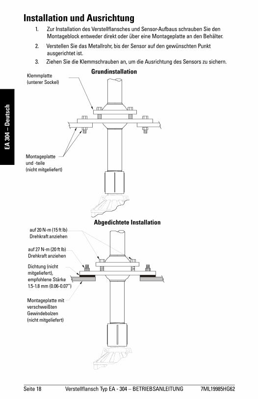
Installation und Ausrichtung 1. Zur Installation des Verstellflansches und Sensor-Aufbaus schrauben Sie den
Montageblock entweder direkt oder über eine Montageplatte an den Behälter.
2. Verstellen Sie das Metallrohr, bis der Sensor auf den gewünschten Punkt
ausgerichtet ist.
3. Ziehen Sie die Klemmschrauben an, um die Ausrichtung des Sensors zu sichern.
Klemmplatte
(unterer Sockel)
Montageplatte
und -teile
(nicht mitgeliefert)
Montageplatte mit
verschweißten
Gewindebolzen
(nicht mitgeliefert)
Dichtung (nicht
mitgeliefert),
empfohlene Stärke
1.5-1.8 mm (0.06-0.07”)
auf 27 N-m (20 ft lb)
Drehkraft anziehen
auf 20 N-m (15 ft lb)
Drehkraft anziehen
Grundinstallation
Abgedichtete Installation

7ML19985HG62 Easy Aimer 304 – INSTRUCCIONES DE USO Page 19
mm
mm
m
EA 304 – Español
Milltronics Easy Aimer - 304La brida de fijación Easy Aimer de acero inoxidable permite la orientación de los sensores ultrasónicos de Siemens Milltronics en la medida de nivel.
Montaje1. Preparar el kit de fijación Easy Aimer según se indica. Para obtener los mejores
resultados, eliminar cualquier polvo presente en el pivote esférico. No apriete los tornillos de fijación.
2. Posicionar el cable del transductor en el acoplamiento y el tubo proporcionados. Acoplar el sensor ultrasónico al tubo de mediante el acoplamiento de reducción. Si el
diámetro del transductor es superior a 148 mm (5,8"), utilizar la placa de montaje del cliente. Para garantizar el sellado, utilizar la junta de sellado del cliente.
Orificio de montaje (x 3), diámetro 11 mm (7/16”) para M8
ó 3/8” . Separación de 120°, diámetro central 157 mm
Tornillos de fijación (x 3)
Tornillo para conexión a tierra
178 mm
(7")
1" NPT ó BSP
Placa de fijación (parte superior)
Bloque de montaje (parte inferior)
Junta de sellado del cliente,
espesor recomendado 1,5-1,8 mm
(0,06-0,07”) (si necesario)
Placa de montaje del
cliente (si necesario)
Acoplamiento típico
Sensor ultrasónico
Siemens Milltronics (modelo
generalmente utilizado)
27°
135 mm (5,3")
nominal
ø 127 mm (5") (general-mente)
10 mm
(0,38")
170 mm
(6,7")
Prensa estopas y acomplamiento M20 (opción)
Page 20 Easy Aimer 304 – INSTRUCCIONES DE USO 7ML19985HG62
mm
mm
m
EA 3
04 –
Esp
añol
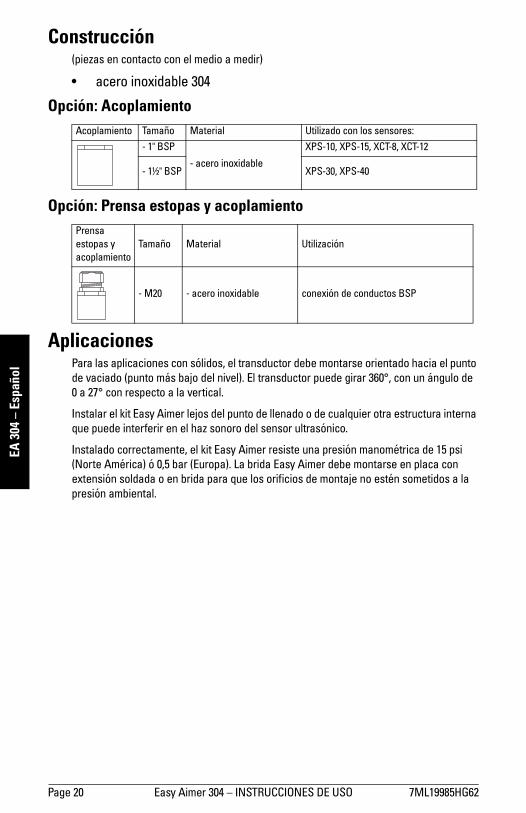
Construcción(piezas en contacto con el medio a medir)
• acero inoxidable 304
Opción: Acoplamiento
Opción: Prensa estopas y acoplamiento
AplicacionesPara las aplicaciones con sólidos, el transductor debe montarse orientado hacia el punto
de vaciado (punto más bajo del nivel). El transductor puede girar 360°, con un ángulo de 0 a 27° con respecto a la vertical.
Instalar el kit Easy Aimer lejos del punto de llenado o de cualquier otra estructura interna que puede interferir en el haz sonoro del sensor ultrasónico.
Instalado correctamente, el kit Easy Aimer resiste una presión manométrica de 15 psi (Norte América) ó 0,5 bar (Europa). La brida Easy Aimer debe montarse en placa con extensión soldada o en brida para que los orificios de montaje no estén sometidos a la
presión ambiental.
Acoplamiento Tamaño Material Utilizado con los sensores:
- 1" BSP
- acero inoxidable
XPS-10, XPS-15, XCT-8, XCT-12
- 1½" BSP XPS-30, XPS-40
Prensa
estopas y
acoplamiento
Tamaño Material Utilización
- M20 - acero inoxidable conexión de conductos BSP
7ML19985HG62 Easy Aimer 304 – INSTRUCCIONES DE USO Page 21
mm
mm
m
EA 304 – Español
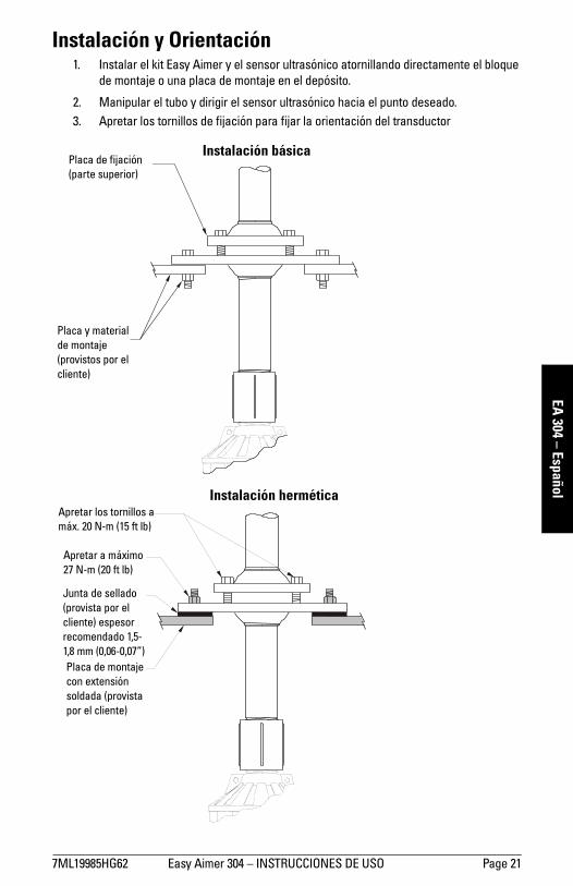
Instalación y Orientación1. Instalar el kit Easy Aimer y el sensor ultrasónico atornillando directamente el bloque
de montaje o una placa de montaje en el depósito.
2. Manipular el tubo y dirigir el sensor ultrasónico hacia el punto deseado.
3. Apretar los tornillos de fijación para fijar la orientación del transductor
Placa de fijación
(parte superior)
Placa y material
de montaje
(provistos por el
cliente)
Placa de montaje
con extensión
soldada (provista
por el cliente)
Junta de sellado
(provista por el
cliente) espesor
recomendado 1,5-
1,8 mm (0,06-0,07”)
Apretar a máximo
27 N-m (20 ft lb)
Apretar los tornillos a
máx. 20 N-m (15 ft lb)
Instalación básica
Instalación hermética
Page 22 Easy Aimer 304 – INSTRUCTIONS D’UTILISATION 7ML19985HG62
mm
mm
m
EA 3
04 –
Fra
nçai
s
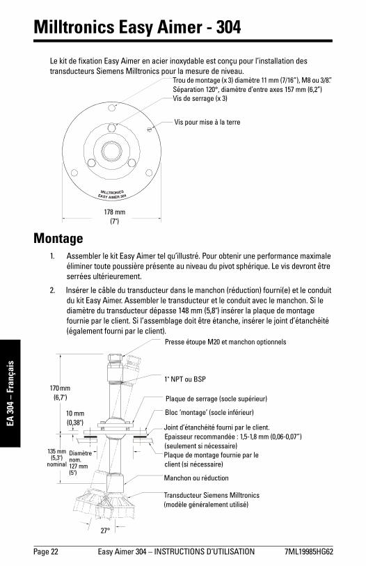
Milltronics Easy Aimer - 304
Le kit de fixation Easy Aimer en acier inoxydable est conçu pour l’installation des
transducteurs Siemens Milltronics pour la mesure de niveau.
Montage1. Assembler le kit Easy Aimer tel qu’illustré. Pour obtenir une performance maximale
éliminer toute poussière présente au niveau du pivot sphérique. Le vis devront être serrées ultérieurement.
2. Insérer le câble du transducteur dans le manchon (réduction) fourni(e) et le conduit
du kit Easy Aimer. Assembler le transducteur et le conduit avec le manchon. Si le diamètre du transducteur dépasse 148 mm (5,8") insérer la plaque de montage fournie par le client. Si l’assemblage doit être étanche, insérer le joint d’étanchéité
(également fourni par le client).
Trou de montage (x 3) diamètre 11 mm (7/16”), M8 ou 3/8”.
Séparation 120°, diamètre d’entre axes 157 mm (6,2’’)
Vis de serrage (x 3)
Vis pour mise à la terre
178 mm
(7")
1" NPT ou BSP
Plaque de serrage (socle supérieur)
Bloc ’montage’ (socle inférieur)
Joint d’étanchéité fourni par le client.
Epaisseur recommandée : 1,5-1,8 mm (0,06-0,07”)
(seulement si nécessaire)
Plaque de montage fournie par le
client (si nécessaire)
Manchon ou réduction
Transducteur Siemens Milltronics
(modèle généralement utilisé)
27°
135 mm (5,3")
nominal
Diamètre nom. 127 mm (5")
10 mm
(0,38")
170 mm
(6,7")
Presse étoupe M20 et manchon optionnels

7ML19985HG62 Easy Aimer 304 – INSTRUCTIONS D’UTILISATION Page 23
mm
mm
m
EA 304 – Français
Construction(pièces en contact avec le produit mesuré)
• acier inoxydable 304
Manchon optionnel
Presse étoupe et manchon optionnels
ApplicationPour les applications en milieu solide, le transducteur doit être installé de sorte qu’il soit dirigé vers le point de vidange. Le kit de fixation permet de tourner le transducteur de
360°, avec une inclinaison de 0 à 27°.
Installer le kit de fixation loin du point de remplissage du réservoir ou de toute structure
interne pouvant interférer avec le faisceau d’émission du transducteur ultrasonique.
Installé correctement, le kit Easy Aimer peut résister à des pressions de 0,5 bar (Europe)
ou 15 psi (Amérique du Nord).
Le kit de fixation doit être monté sur une plaque ayant une rallonge soudée ou une bride
pour assurer l’isolation des trous de montage contre la pression.
Manchon Dim. Matériau Utilisé avec les transducteurs :
- 1" BSP
- acier inoxydable
XPS-10, XPS-15, XCT-8, XCT-12
- 1½" BSP XPS-30, XPS-40
Presse
étoupe eet
manchon
Dim. Matériau Utilisation
- M20 - stainless steelRaccord presse étoupe / manchon et
conduit BSP.
Page 24 Easy Aimer 304 – INSTRUCTIONS D’UTILISATION 7ML19985HG62
mm
mm
m
EA 3
04 –
Fra
nçai
s
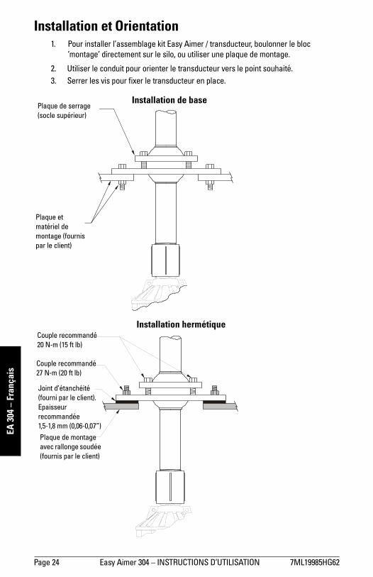
Installation et Orientation1. Pour installer l’assemblage kit Easy Aimer / transducteur, boulonner le bloc
’montage’ directement sur le silo, ou utiliser une plaque de montage.
2. Utiliser le conduit pour orienter le transducteur vers le point souhaité.
3. Serrer les vis pour fixer le transducteur en place.
Plaque de serrage
(socle supérieur)
Plaque et
matériel de
montage (fournis
par le client)
Plaque de montage
avec rallonge soudée
(fournis par le client)
Joint d’étanchéité
(fourni par le client).
Epaisseur
recommandée
1,5-1,8 mm (0,06-0,07”)
Couple recommandé
27 N-m (20 ft lb)
Couple recommandé
20 N-m (15 ft lb)
Installation de base
Installation hermétique

Notes
Notes.fm Page 1 Thursday, October 11, 2001 8:48 AM

Notes
Notes.fm Page 1 Thursday, October 11, 2001 8:48 AM

IQ300IX.fm Page 5 Tuesday, October 2, 2001 1:43 PM

*7ml19985hg02*Rev. 2.0
www.siemens.com/processautomation
Siemens Milltronics Process Instruments Inc.1954Technology Drive, P.O. Box 4225Peterborough, ON, Canada K9J 7B1Tel: (705) 745-2431 Fax: (705) 741-0466Email: [email protected]
Siemens Milltronics Process Instruments Inc. 2005Subject to change without prior notice
Printed in Canada