engineers manual - classeq
TRANSCRIPT

Engineers manual Under counter machines

Engineers manual Under counter machines
Page 1
Table of Contents
1. INTRODUCTION ........................................................................................................................................... 3
INSTALLATION AND COMMISSIONING ............................................................................................................... 3 1.1
SERVICE AND REPAIRS .................................................................................................................................. 3 1.2
MODIFICATION .............................................................................................................................................. 3 1.3
2. EXPLANATION OF SYMBOLS USED ......................................................................................................... 3
3. WARNING AND SAFETY INFORMATION .................................................................................................. 3
DANGER WARNINGS ...................................................................................................................................... 3 3.1
WARNINGS ................................................................................................................................................... 3 3.2
CAUTIONS .................................................................................................................................................... 3 3.3
4. MACHINE SPECIFICATIONS ...................................................................................................................... 4
SYSTEMS MATRIX ......................................................................................................................................... 4 4.1
MECHANICAL SPECIFICATIONS AND SITE REQUIREMENTS ................................................................................. 4 4.2
WIRING ........................................................................................................................................................ 4 4.3
COMPONENTS .............................................................................................................................................. 5 4.4
4.4.1 Pump wiring ........................................................................................................................................ 6 4.4.2 Winding legend ................................................................................................................................... 6
5. WATER PATHS ............................................................................................................................................ 7
PRESSURISED SYSTEM.................................................................................................................................. 7 5.1
UNPRESSURISED SYSTEM ............................................................................................................................. 8 5.2
WATER SOFTENER SYSTEM ........................................................................................................................... 9 5.3
WATER SOFTENER UNIT .............................................................................................................................. 10 5.4
WATER WAYS LEGEND ................................................................................................................................ 11 5.5
6. LOGIC ......................................................................................................................................................... 12
INDICATOR LOGIC ........................................................................................................................................ 12 6.1
6.1.1 Heating indicator .............................................................................................................................. 12 6.1.2 Cycle indicator .................................................................................................................................. 12 FILL AND HEAT ............................................................................................................................................ 13 6.2
6.2.1 Pressurised fill and heat ................................................................................................................... 13 6.2.2 Unpressurised fill and heat ............................................................................................................... 14 STANDBY ................................................................................................................................................... 15 6.3
WASH AND RINSE ........................................................................................................................................ 16 6.4
DRAIN ........................................................................................................................................................ 17 6.5
CHEMICAL DOSING ...................................................................................................................................... 18 6.6
WATER SOFTENER UNIT .............................................................................................................................. 18 6.7
7. COMMISSIONING/SERVICE MODES ....................................................................................................... 19
COMMISSIONING/SERVICE INTERFACE .......................................................................................................... 19 7.1
COMMISSIONING MODE ............................................................................................................................... 19 7.2
SETTING CHEMICAL DOSAGE ....................................................................................................................... 20 7.3
PRIMING CHEMICALS ................................................................................................................................... 20 7.4
INTEGRAL WATER SOFTENER (IF FITTED) ...................................................................................................... 20 7.5
7.5.1 Commissioning the water softener unit ............................................................................................ 20 7.5.2 Setting the water softener ................................................................................................................ 21 7.5.3 Water softener settings .................................................................................................................... 21 WASH AND RINSE TANK TEMPERATURES ...................................................................................................... 21 7.6
SERVICE MODE ........................................................................................................................................... 22 7.7
7.7.1 Program value .................................................................................................................................. 22 7.7.2 Loads ................................................................................................................................................ 23 7.7.3 Errors ................................................................................................................................................ 24 7.7.4 Statistics ........................................................................................................................................... 26

Engineers manual Under counter machines
Page 2
8. CONTROL UNIT ......................................................................................................................................... 27
INPUTS AND OUTPUTS ................................................................................................................................. 27 8.1
8.1.1 Main board ....................................................................................................................................... 27 8.1.2 Water softener board........................................................................................................................ 28 BOARD SETUP ............................................................................................................................................ 29 8.2
9. TOOL LIST .................................................................................................................................................. 30
10. NOTES ........................................................................................................................................................ 30
11. QUICK REFERENCE .................................................................................................................................. 31

Engineers manual Under counter machines
Page 3
1. Introduction
Prior to reading this manual it is essential that you are familiar with the contents and subject matter covered by the “Installation and Operation manual”.
Installation and commissioning 1.1
Installation and commissioning instructions are detailed in the “Installation and Operation manual” and should always be followed. Incorrect installation may invalidate any warranties.
Service and repairs 1.2
Repairs to the machine should only be carried out by a Classeq approved/trained technician using genuine Classeq parts. Failure to do so may invalidate any warranties.
Modification 1.3
Classeq reserves the right to modify the machine or the contents of this manual without notice.
2. Explanation of symbols used
DANGER!
Warning against potentially
serious or fatal injuries to persons
if the described precautionary
measures are not taken.
► This symbol refers to a chapter with more detailed information
Warning!
Warning against potentially minor
injuries to persons or material
damage if the described
precautionary measures are not
taken
1 Refer to foot note at bottom of page
Caution
Warning against defects in or
destruction of the product if the
described precautionary
measures are not taken.
Recycle
3. Warning and safety information
Danger warnings 3.1
Unless the machine has been isolated from the supply there will always be potential for mains voltage to any components in the machine. (►8)
Warnings 3.2
DO NOT run the machine if there is no salt in the salt reservoir, as this will allow lime scale to build up, also any lime scale will invalidate your warranty.
DO NOT add any chemicals, such as detergent or rinse aid to the reservoir. These will cause damage to the machine. (►7.5)
Cautions 3.3
Only use granulated salt (max. grain size 5 – 7 mm). Salt tablets are not suitable.
If the reservoir cap is not properly secured, water and/or chemicals can leak in or out of the unit causing damage to the machine. (►7.5)
Repairs to the machine should only be done with the mains supply isolated. (►8)
Any changes made to will not be saved if power to the machine is disrupted before completely exiting service mode. (►8.2)

Engineers manual Under counter machines
Page 4
4. Machine specifications
Systems matrix 4.1
Below is a table describing the various systems available for the different machine types.
Machine type
13A (11A1)
28A 3 Phase Rinse
booster pump
WRAS approved
air gap
Water softener
Drain pump
Gravity drain
900002872 ● ○ ○ ○ ○ ○ ◐ ●
900002883 ● ○ ○ ○ ○ ○ ◐ ●
900002894 ◐ ● ◐ ● ● ◐ ● ◐
900002905 ◐ ● ◐ ○ ○ ○ ● ◐
900002916 ◐ ● ◐ ● ● ◐ ● ◐
● - Standard
◐ - Optional
○ – Not available
Mechanical specifications and site requirements 4.2
For details on machine dimensions and site requirements refer to the “Installation and Operation manual” for the machine.
Wiring 4.3
For detailed wiring information refer to the relevant wiring diagram for the machine.
1 In machines with this as an option only 1 leg of the 6kW rinse element will be used.
2 G350
3 G400; D400
4 G400 DUO, D400 DUO, G400 DUO WS; D400 DUO WS
5 G500; D500
6 G500 DUO; D500DUO; G500DUO WS; D500 DUO WS

Engineers manual Under counter machines
Page 5
Components 4.4
The table below indicates the electrical components in the machines and their electrical specifications
Component Voltage
range (V) Frequency
(Hz) Current
(A) Power (W) Resistance (Ω)
Inlet solenoid 220-240 50/60 0.026 6 4110
Rinse element
2600 220-240 50/60
5.65 2 x 1300 41.95
6000 8.68 3 x 2000 27.25
Rinse pump
Small7
220-240 50 0.45 100 M – 41.9
A – 67.6
220-240 60 0.47 105 M – 39
A – 56
Large
220-240 50 0.7 190 M – 32.2
A – 43.3
220-240 60 0.66 146 M – 26.78
A – 34.8
Wash element 220-240 50/60 8.7 2000 27.3
Wash pump
Small
220-240 50 1.2 250 M – 22.76
A – 54.1
220-240 60 1.25 255 M – 17.3
A – 42.1
Large8
220-240 50 2.55 580 M – 9.52
A – 18.97
220-240 60 2.42 550 M – 8.06
A – 16.11
Drain pump 220-240 50 0.2 30 145.1
208-240 60 0.15 32 76
Contactors 1 Pole9 220-240 50/60 0.005 1.2 11030
3 Pole10 220-240 50/60 0.006 1.3 6760
Detergent pump 220-240 50/60 0.03 8 3180
Rinse aid pump 220-240 50/60 0.03 8 3180
7 400mm machines only
8 500mm machines only
9 2600W rinse element machines only
10 6000W rinse element machines only

Engineers manual Under counter machines
Page 6
4.4.1 Pump wiring
The windings of the wash and rinse pumps are wired to the plug as below:
4.4.2 Winding legend
Key Description
M Main winding
A Auxiliary winding
PE Earth wire (Green and Yellow)
BU Blue wire
BK Black wire

Engineers manual Under counter machines
Page 7
5. Water paths
Pressurised system 5.1
Engineers manual Under counter machines
Page 8
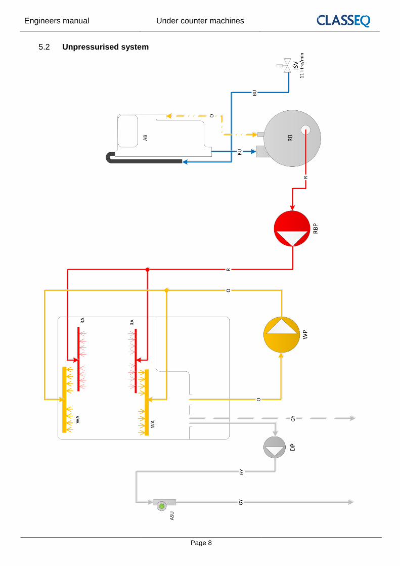
Unpressurised system 5.2

Engineers manual Under counter machines
Page 9
Water softener system 5.3

Engineers manual Under counter machines
Page 10
Water softener unit 5.4

Engineers manual Under counter machines
Page 11
Water ways legend 5.5
Key Description
ISV Inlet solenoid valve
LCV Lateral check valve
AB WRAS approved type AB air gap
RB Rinse tank
RBP Rinse booster pump
WP Wash pump
DP Drain pump
RA Rinse arm
WA Wash arm
WSU Water softener unit
NRV Non-return valve
ASU Anti-syphon unit
SR Salt reservoir
Res Resin chamber
Solenoid valve
Paddle sensor
Ball valve
Air gap
Switching valve
Non return ball valve
BU Incoming water
GR Softened water
R Rinse water
O Wash water
GY Waste water – Pumped drain
GY Waste water – Gravity drain
P Waste water – Water softener
O Breather
Engineers manual Under counter machines
Page 12
6. Logic
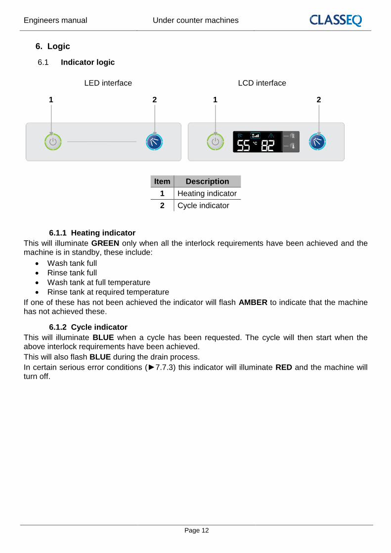
Indicator logic 6.1
LED interface LCD interface
Item Description
1 Heating indicator
2 Cycle indicator
6.1.1 Heating indicator
This will illuminate GREEN only when all the interlock requirements have been achieved and the machine is in standby, these include:
Wash tank full
Rinse tank full
Wash tank at full temperature
Rinse tank at required temperature
If one of these has not been achieved the indicator will flash AMBER to indicate that the machine has not achieved these.
6.1.2 Cycle indicator
This will illuminate BLUE when a cycle has been requested. The cycle will then start when the above interlock requirements have been achieved.
This will also flash BLUE during the drain process.
In certain serious error conditions (►7.7.3) this indicator will illuminate RED and the machine will turn off.
1 2 1 2

Engineers manual Under counter machines
Page 13
Fill and heat 6.2
6.2.1 Pressurised fill and heat
Pressurised machines fill and rinse using the solenoid valve and site water pressure. These machines will fill in the following manner:
1) Activate solenoid valve until the wash air pressure sensor reads a minimum level. 2) Heat the rinse tank to a specified transfer temperature; this is lower than the rinse
temperature to ensure that the wash tank is not too hot after the fill cycle. 3) Activate the solenoid valve to transfer water through the rinse tank to the wash tank for a
specified time. 4) Repeat steps 1 to 3 until the wash tank is full. 5) The machine will continue to heat until the rinse boiler and wash tank have both reached
the specified temperatures.
Below is a flow diagram to represent this.
Engineers manual Under counter machines
Page 14
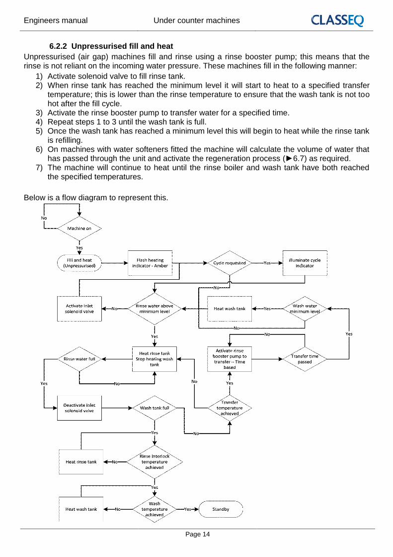
6.2.2 Unpressurised fill and heat
Unpressurised (air gap) machines fill and rinse using a rinse booster pump; this means that the rinse is not reliant on the incoming water pressure. These machines fill in the following manner:
1) Activate solenoid valve to fill rinse tank. 2) When rinse tank has reached the minimum level it will start to heat to a specified transfer
temperature; this is lower than the rinse temperature to ensure that the wash tank is not too hot after the fill cycle.
3) Activate the rinse booster pump to transfer water for a specified time. 4) Repeat steps 1 to 3 until the wash tank is full. 5) Once the wash tank has reached a minimum level this will begin to heat while the rinse tank
is refilling. 6) On machines with water softeners fitted the machine will calculate the volume of water that
has passed through the unit and activate the regeneration process (►6.7) as required. 7) The machine will continue to heat until the rinse boiler and wash tank have both reached
the specified temperatures.
Below is a flow diagram to represent this.

Engineers manual Under counter machines
Page 15
Standby 6.3
While the machine is in standby it will monitor the wash and rinse temperatures and levels and maintain these as required.
Below is a flow diagram to represent this.

Engineers manual Under counter machines
Page 16
Wash and rinse 6.4
If a cycle is requested when the machine is in standby the wash and rinse, process on all machines, follow the below procedure:
1) Illuminate indicator 2) Start wash cycle and heat rinse tank to full temperature. 3) Once the rinse has achieved the required temperature and the wash time has elapsed there
is a pause to allow the water to drip down. If the rinse temperature is not achieved the wash cycle is extended up to a maximum time out.
4) Start rinse cycle for the specified time. 5) There is a short pause after the rinse to allow water to drip down then the cycle indicator
will turn off.
Below is a flow diagram to represent this.

Engineers manual Under counter machines
Page 17
Drain 6.5
The drain of the machine functions in two ways:
1. It monitors the water level in the wash tank and drains away any excess water at any time. 2. If the machine is turned off and the drain cycle is selected, this function will follow the below
process: a. Start draining the machine. b. Once the water reaches the minimum level in the wash tank an “Assisted clean”
function will transfer water from the rinse boiler in the same fashion as it fills (►6.2) while continuing to drain (If the door is open at this time the “Assisted clean” will be cancelled).
c. Once the wash tank reaches a minimum level again it activates a timer to drain out the remaining water.
Below is a flow diagram to represent this.

Engineers manual Under counter machines
Page 18
Chemical dosing 6.6
The machine doses chemical at two different stages:
1. While filling the machine: a. The detergent is dosed into the wash tank with each transfer. At the end of the fill the
rinse aid is dosed into the rinse tank. 2. While cycling the machine:
a. When a cycle is selected the detergent will dose into the wash tank. This will not occur on the first cycle after filling the machine.
b. After each cycle the rinse aid is dosed into the rinse boiler for the amount of water used.
Water softener unit 6.7
On machines with the integral water softener fitted the machine will monitor the amount of water passing through the resin of the softener unit and regenerate at intervals required by the water hardness setting (►7.5.3).
The regeneration process passes salt water into the resin, allows a contact period for the salt to ‘scrub’ the resin then flushes this salt water out the waste.
Below is the timing for this function of the water softener unit.
Function Rinse
until resin exhausted
Pause Salt to resin
Pause Pressurise Regen
(Contact) Pause Flush Pause
Time 3s 25s 3s 1.5s 20s 3s 12s 3s
ISV (O8)
WS salt valve (O11)
WS waste valve (O12)

Engineers manual Under counter machines
Page 19
7. Commissioning/service modes
Commissioning/service interface 7.1
Item Description
1 Exit button
2 Enter button
3 Cycle indicator
4 Display
5 Up button
6 Down button
Commissioning mode 7.2
With the machine turned on at the mains electrical supply but off at the display, press and hold the Exit (1) and Enter (2) buttons for 3sec. the display (4) will show the first menu item and the cycle indicator (3) will illuminate red.
If no buttons have been pressed for a period of time the machine will cancel this mode and return to the off state.
Below is the complete menu list.
Display Description Units
** Rinse aid setting (e.g. = 1.5mL/L) 0.1 x mL/L
Rinse aid prime 0 = Off
= On
** Detergent setting (e.g. = 3.3mL/L) 0.1 x mL/L
Detergent prime 0 = Off
= On
** Water softener setting (if fitted) °dH
** Refers to the setting of the chemical dosing. For example the default setting for rinse aid is 1ml of chemical per litre of water this will be displayed as ‘ ’ the default setting for detergent is 3ml of chemical per litre of water this will be displayed as ‘ ’
1 4 5 2
6 3
LED interface
1 4 5 2
6 3
LCD interface

Engineers manual Under counter machines
Page 20
Setting chemical dosage 7.3
1. Enter commissioning mode (►7.2). 2. Using the up and down keys (5 & 6), scroll to the rinse aid setting menu item ( **) and
press enter (2). 3. The display will flash. 4. Use the up and down keys (5 & 6) to scroll to the required setting and press enter (2). 5. Using the up and down keys (5 & 6), scroll to the detergent setting menu item ( **) and
press enter (2). 6. The display will flash. 7. Use the up and down keys (5 & 6) to scroll to the required setting and press enter (2). 8. Press exit (1) until you are out of commissioning mode.
Priming chemicals 7.4
Before the machine can be used the chemical tubes will need to be filled with chemicals, in order to do this you will need to follow the below instructions to prime the chemical pumps.
1. Enter commissioning mode (►7.2). 2. Using the up and down keys (5 & 6), scroll to the rinse aid prime menu item ( ) and
press enter (2) 3. The display will flash and will change to . 4. This will continually run the rinse aid pump for a maximum of 12 minutes and draw
chemicals into the machine. When the chemicals have reached the back of the machine press enter (2) again to stop the pump.
5. The display will stop flashing and return to . 6. Using the up and down keys (5 & 6), scroll to the detergent prime menu item ( ) and
press enter (2) 7. The display will flash and will change to . 8. This will continually run the detergent pump for a maximum of 2 minutes and draw
chemicals into the machine. When the chemicals have reached the back of the machine press enter (2) again to stop the pump.
9. The display will stop flashing and return to . 10. Press exit (1) until you are out of commissioning mode.
Integral water softener (if fitted) 7.5
7.5.1 Commissioning the water softener unit
To commission the water softener unit follow the instructions below:
1. Open the door to the machine. 2. Remove the right hand basket ramp. 3. Open the salt reservoir cap at the back right hand corner of the wash tank. 4. Fill the reservoir with fresh water. 5. Using the salt funnel supplied fill the reservoir with approximately 1.5kg of granulated salt. 6. Wipe away any excess or spilt salt from the cabinet and the reservoir opening. 7. Refit the cap to the reservoir, ensure that the cap is fitted flat and secure.

Engineers manual Under counter machines
Page 21
Warning
DO NOT run the machine if there is no salt in the salt reservoir, as this will allow lime scale to build up, also any lime scale will invalidate your warranty.
DO NOT add any chemicals, such as detergent or rinse aid to the reservoir. These will cause damage to the machine.
Caution
Only use granulated salt (max. grain size 5 – 7 mm). Salt tablets are not suitable.
If the reservoir cap in not properly secured, water and/or chemicals can leak in or out of the unit causing damage to the machine.
7.5.2 Setting the water softener
Check the water hardness of your water supply (°d). Once you have this data follow the steps below.
1. Refer to Appendix A to find the setting required for your water hardness (►7.5.3). 2. Enter commissioning mode (►7.2) 3. Using the up and down keys (5 & 6), scroll to the water hardness menu item ( **) and press
enter (2). 4. The display will flash. 5. Use the up and down keys (5 & 6) to scroll to the setting you require and press enter (2). 6. Press exit (1) until you are out of commissioning mode.
7.5.3 Water softener settings Water softener setting °dH °e / °clark °fH ppm Water volume No of cycles
Deactivated 1 0.8 0.6 18 48.1 L 16
2 1.6 1.1 36 45.7 L 15
3 2.4 1.7 54 43.4 L 14
4 3.2 2.2 71 41.2 L 14
5 4.0 2.8 89 39.0 L 13
6 4.8 3.4 107 36.9 L 12
7 5.6 3.9 125 34.9 L 12
8 6.4 4.5 143 32.9 L 11
9 7.2 5.0 161 31.0 L 10
10 8.0 5.6 179 29.2 L 10
11 8.8 6.2 196 27.4 L 9
12 9.6 6.7 214 25.7 L 9
13 10.4 7.3 232 24.1 L 8
14 11.2 7.8 250 22.5 L 7
15 12.0 8.4 268 21.0 L 7
16 12.8 9.0 286 19.5 L 7
17 13.6 9.5 303 18.2 L 6
18 14.4 10.1 321 16.9 L 6
19 15.2 10.6 339 15.9 L 5
20 16.0 11.2 357 14.4 L 5
21 16.8 11.8 375 13.3 L 4
22 17.6 12.3 393 12.3 L 4
23 18.4 12.9 411 11.3 L 4
24 19.2 13.4 428 10.4 L 3
25 20.0 14.0 446 9.6 L 3
26 20.8 14.6 464 8.8 L 3
27 21.6 15.1 482 8.1 L 3
28 22.4 15.7 500 7.4 L 2
29 23.2 16.2 518 6.8 L 2
30 24.0 16.8 536 6.3 L 2
Engineers manual Under counter machines
Page 22
Wash and rinse tank temperatures 7.6The wash and rinse boiler temperatures have been pre-set to temperatures that comply with
environmental health standards and cannot be adjusted.
Service mode 7.7
With the machine turned on at the mains electrical supply but off at the display, press and hold the Exit (1) and Enter (2) buttons for 6sec. the display (4) will show the first menu item and the cycle indicator (3) will illuminate red.
If no buttons have been pressed for a period of time the machine will cancel this mode and return to the off state.
Below is the complete menu list.
Display Description
Program values
L Loads
Errors
Statistics
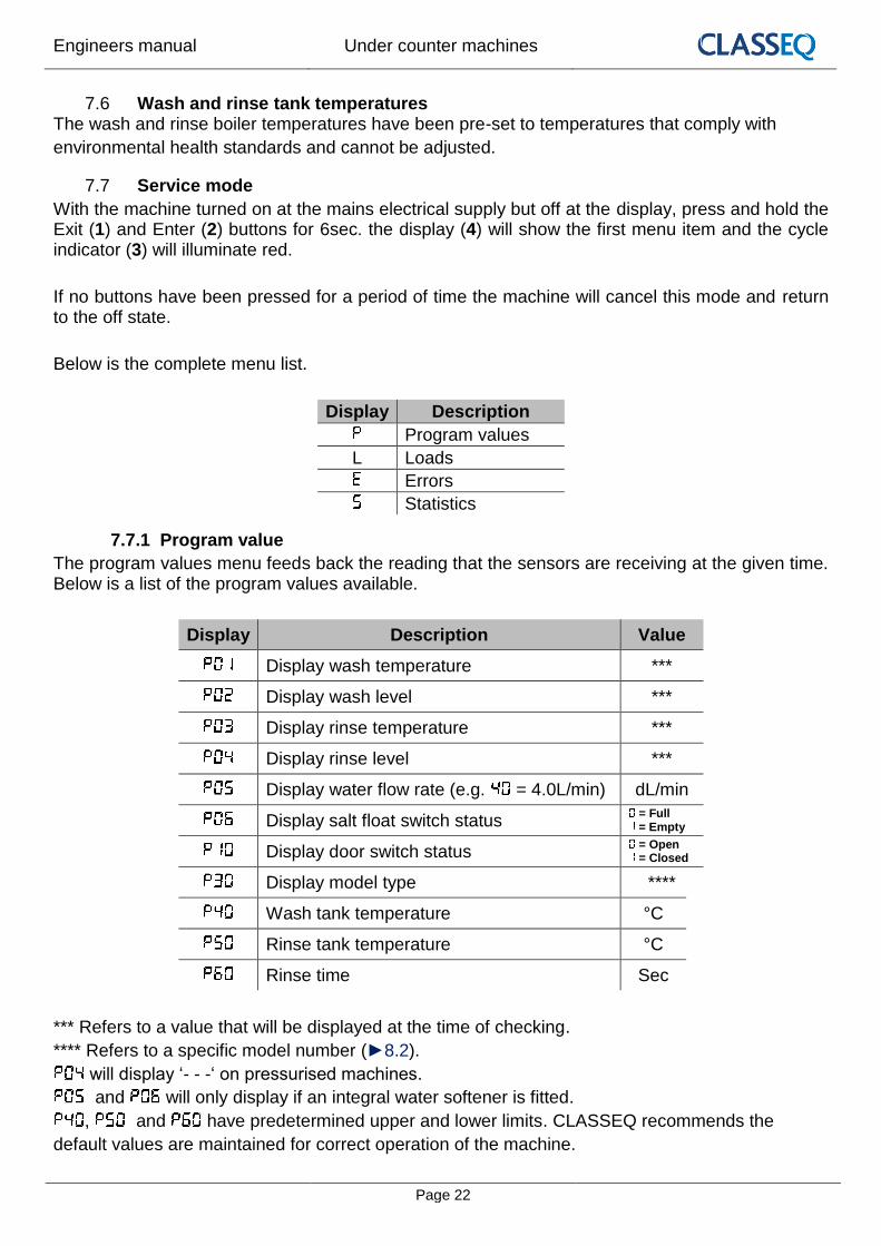
7.7.1 Program value
The program values menu feeds back the reading that the sensors are receiving at the given time. Below is a list of the program values available.
Display Description Value
Display wash temperature ***
Display wash level ***
Display rinse temperature ***
Display rinse level ***
Display water flow rate (e.g. = 4.0L/min) dL/min
Display salt float switch status = Full = Empty
Display door switch status = Open = Closed
Display model type ****
Wash tank temperature °C
Rinse tank temperature °C
Rinse time Sec
*** Refers to a value that will be displayed at the time of checking.
**** Refers to a specific model number (►8.2).
will display ‘- - -‘ on pressurised machines.
and will only display if an integral water softener is fitted.
, and have predetermined upper and lower limits. CLASSEQ recommends the
default values are maintained for correct operation of the machine.

Engineers manual Under counter machines
Page 23
7.7.2 Loads
The loads menu allows activation of specific loads within the machine in order to test their function. Some loads have safety criteria that need to be achieved before the load can be activated, if the component does not activate when the load is activated first check the continuity or resistance of the component through the harness.
Below is a list of loads that can be activated, via the up and down keys (5 & 6), and their required criteria. Each of the loads has a safety timeout applied to reduce the risk of wear on the components.
Display Description Value Safety criteria
Wash pump = Off = On
Wash water level above minimum level and door closed.
Wash pump + soft start = Off = On
Wash water level above minimum level and door closed.
Wash tank heat element = Off = On
Wash water level above minimum level.
Detergent pump = Off = On
Rinse pump = Off = On
Rinse aid pump = Off = On
Wash tank heat element - Spare = Off = On
Wash water level above minimum level.
Rinse tank heat element = Off = On
Rinse water level above minimum level and door closed.
Inlet solenoid valve = Off = On
Drain pump = Off = On
WS Salt valve = Off = On
WS Waste valve = Off = On
WS Waste valve + inlet valve = Off = On
will display ‘- - -‘ on pressurised machines.
and will display if an integral water softener is fitted.

Engineers manual Under counter machines
Page 24
7.7.3 Errors
The errors menu feeds back the last 40 errors on the machine in order to help identify the fault. Use the up (5) and down (6) keys to cycle through the list, the list does not roll over and will always start on the most recent error.
Below is a list of error codes and their possible cause. These are given as an aid only; all other possible causes of faults should be investigated before repair is carried out.
Display Title Description Possible cause
New day Displays each time the machine is switched on.
Wash tank pressure sensor
Invalid signal from the wash pressure sensor.
Wash tank pressure sensor faulty or disconnected.
Wash tank temperature sensor
Invalid signal from the wash temperature sensor.
Wash tank temperature sensor faulty.
Rinse tank pressure sensor
Invalid signal from the rinse pressure sensor.
Rinse tank pressure sensor faulty or disconnected.
Rinse tank temperature sensor
Invalid signal from the rinse temperature sensor.
Rinse tank temperature sensor faulty.
Wash water level unchanged during cycle.
Wash tank level not changed after soft start, repeated 3 times before error logged.
Wash pump blocked. Wash arm blocked. Wash pump capacitor failed. Wash pump failed. Board output relay failed.
Rinse water level unchanged during rinse.
Rinse tank level not changed when starting the rinse pump.
Rinse arm blocked. Rinse pump blocked. Rinse pump capacitor failed. Rinse pump failed. Board output relay failed.
Rinse tank temperature not achieved.
Rinse tank has not reached the target temperature within 60 minutes.
Rinse tank over heat thermostat tripped. Rinse tank heating element failed. Rinse tank element contactor failed. Board output relay failed.
Wash tank temperature not achieved.
Wash tank has not reached the target temperature within 60 minutes.
Wash tank over heat thermostat tripped. Wash tank heating element failed. Board output relay failed.
Wash water level unchanged during soft start.
Wash tank level not changed during soft start.
Wash pump blocked. Wash arm blocked. Wash pump capacitor failed. Wash pump failed. Board triac failed.

Engineers manual Under counter machines
Page 25
Salt missing
Only in machines with water softener fitted. Salt level in reservoir is low for 30 seconds.
No salt in reservoir. Salt reed switch failed.
Display communication failure
No signal from the user interface unit.
User interface not correctly connected. User interface failed.
Wash tank fill Wash tank has not filled within the required number of transfers.
Drain plug not inserted. Machine leaking. Very low water pressure (pressurised machines).
Rinse tank fill timeout
Rinse tank has not filled within 5 minutes.
Water supply not connected or turned on. Very low water pressure. Solenoid valve failed.
Door switch Door switch has not changed position for the past 20 cycles
Door switch failed.
Paddle flow sensor
Only in machines with water softener fitted. Paddle sensor in air gap is not responding during the fill stage.
No water supply. Paddle sensor failed. See to assist.
Wash tank overfill Wash tank has reached the flood risk level.
Site drain blocked. Machine waste hose blocked or kinked. Solenoid failed open. Drain pump failed.
Filter mesh blocked
Water level in wash tank has been reduced to below minimum required level during a wash cycle.
Wash arms blocked. Wash pump blocked. Wash filters blocked. Container in wash tank collecting water.
Rinse tank temperature exceeded
Rinse tank temperature has exceeded the safety limit.
Rinse tank temperature sensor disconnected. Rinse element relay fused. Main board relay fused. Rinse element wired incorrectly.
Wash tank temperature exceeded
Wash tank temperature has exceeded the safety limit.
Wash tank temperature sensor disconnected. Main board relay fused. Wash element wired incorrectly.
Power interruption Power to machine has been interrupted.
Machine isolated from power supply. Power failure.
EEPROM Error EEPROM failed Main board failed
Engineers manual Under counter machines
Page 26
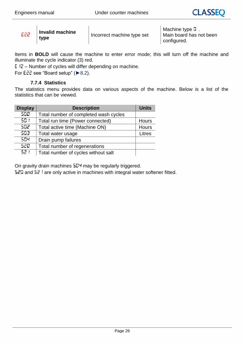
Invalid machine type
Incorrect machine type set Machine type Main board has not been configured.
Items in BOLD will cause the machine to enter error mode; this will turn off the machine and illuminate the cycle indicator (3) red.
– Number of cycles will differ depending on machine.
For see “Board setup” (►8.2).
7.7.4 Statistics
The statistics menu provides data on various aspects of the machine. Below is a list of the statistics that can be viewed.
Display Description Units
Total number of completed wash cycles
Total run time (Power connected) Hours
Total active time (Machine ON) Hours
Total water usage Litres
Drain pump failures
Total number of regenerations
Total number of cycles without salt
On gravity drain machines may be regularly triggered.
and are only active in machines with integral water softener fitted.

Engineers manual Under counter machines
Page 27
8. Control unit
DANGER!
Unless the machine has been isolated from the supply there will always be potential for mains voltage to any components in the machine.
Caution
Repairs to the machine should only be done with the mains supply isolated.
Inputs and outputs 8.1
8.1.1 Main board
Inputs
Label Device
I1 Wash temperature sensor
I2 Wash pressure sensor
I3 Rinse temperature sensor
I4 Rinse pressure sensor
I5 Water softener float switch
I6 Water softener paddle wheel
Bus User interface
Door Door reed switch
PC Production test port
LN Mains power from terminal block

Engineers manual Under counter machines
Page 28
Outputs
Label Load
O1 Wash pump
O2 Wash element
O3 Rinse aid pump
O4 Rinse booster pump
O5 Detergent pump
O6 Aux. wash contactor
O7 Rinse contactor
O8 Inlet solenoid valve
O9 Drain pump
O10 Not used
O11 WS board
O12 WS board
O13 Not used
I/O WS board power
8.1.2 Water softener board
Inputs
Label Device
WS I1 Main board O11 and O12
WS I/O Power from main board
Outputs
Label Load
WS O1 Water softener salt valve
WS O2 Water softener waste valve

Engineers manual Under counter machines
Page 29
Board setup 8.2
In the event of changing a control board the new board will need to be configured to the machine. The board will initially be set to Base set and will give and error and enter error mode if attempted to be turned on. In order to change the base set of the machine follow the instructions below:
Step Instruction
1 Enter service mode (►7.7).
2 Enter the “Program values” menu.
3 Scroll to using the up and down (5 and 6) keys and enter. The display (4) will start to flash.
4 Use the up and down keys (5 and 6) to select the correct base set for the machine.
5 Press enter to select (2).
6 Press exit (1) until completely out of the service mode.
Base set Description
G350
G400
G400 Duo
G400 Duo WS
D400
D400 Duo
D400 Duo WS
G500
G500 Duo
G500 Duo WS
D500
D500 Duo
D500 Duo WS
Caution
Any changes made to will not be saved if power to the machine is disrupted before completely exiting service mode.

Engineers manual Under counter machines
Page 30
9. Tool list
The below list of tools will allow access to all components within the machine:
Tool group Description
Spanner/nut runner/ratchet
5.5mm
7mm
8mm
13mm
Hex key
2mm
3mm
4mm
Posi screw driver No. 2
No. 3
Electrical testing
Ammeter (A)
Capacitance meter (µF)
Resistance meter (Ω)
Continuity ()
10. Notes

Engineers manual Under counter machines
Page 31
11. Quick reference
Dis
pla
yD
esc
rip
tio
nU
nit
sD
isp
lay
r**
Rin
se a
id s
etti
ng
(e.g
. 15
= 1
.5m
L/L)
0.1
x m
L/L
rP0
Rin
se a
id p
rim
e0 =
Off
1 =
On
d**
Det
erge
nt
sett
ing
(e.g
. 33
= 3
.3m
L/L)
0.1
x m
L/L
dP
0D
eter
gen
t p
rim
e0 =
Off
1 =
On
h**
Wat
er s
oft
ener
set
tin
g (i
f fi
tted
)°d
H
Dis
pla
yD
esc
rip
tio
nV
alu
eD
isp
lay
Titl
eD
isp
lay
De
scri
pti
on
Un
its
Dis
pla
y w
ash
tem
per
atu
re**
*N
ew d
ayTo
tal n
um
ber
of
com
ple
ted
was
h c
ycle
s
Dis
pla
y w
ash
leve
l**
*W
ash
tan
k p
ress
ure
se
nso
rTo
tal r
un
tim
e (P
ow
er c
on
nec
ted
)H
ou
rs
Dis
pla
y ri
nse
tem
per
atu
re**
*W
ash
tan
k te
mp
erat
ure
sen
sor
Tota
l act
ive
tim
e (M
ach
ine
ON
)H
ou
rs
Dis
pla
y ri
nse
leve
l**
*R
inse
tan
k p
ress
ure
se
nso
rTo
tal w
ater
usa
geLi
tres
Dis
pla
y w
ater
flo
w r
ate
(e.g
. 40
= 4
.0L/
min
)d
L/m
inR
inse
tan
k te
mp
erat
ure
sen
sor
Dra
in p
um
p f
ailu
res
Dis
pla
y sa
lt f
loat
sw
itch
sta
tus
0 =
Fu
ll
1 =
Em
pty
Was
h w
ater
leve
l un
chan
ged
du
rin
g cy
cle.
Tota
l nu
mb
er o
f re
gen
erat
ion
s
Dis
pla
y d
oo
r sw
itch
sta
tus
0 =
Op
en
1 =
Clo
sed
Rin
se w
ater
leve
l un
chan
ged
du
rin
g ri
nse
.To
tal n
um
ber
of
cycl
es w
ith
ou
t sa
lt
Dis
pla
y m
od
el t
ype
****
Rin
se t
ank
tem
per
atu
re n
ot
ach
ieve
d.
Was
h t
ank
tem
per
atu
re°C
Was
h t
ank
tem
per
atu
re n
ot
ach
ieve
d.
Bas
e s
et
Rin
se t
ank
tem
per
atu
re°C
Was
h w
ater
leve
l un
chan
ged
du
rin
g so
ft s
tart
.
Rin
se t
ime
Sec
Salt
mis
sin
g
Dis
pla
y co
mm
un
icat
ion
fai
lure
Was
h t
ank
fill
Dis
pla
yD
esc
rip
tio
nV
alu
eR
inse
tan
k fi
ll ti
me
ou
t
Was
h p
um
p0
= O
ff
1 =
On
Do
or
swit
ch
Was
h p
um
p +
so
ft s
tart
0 =
Off
1 =
On
Pad
dle
flo
w s
enso
r
Was
h t
ank
he
at e
lem
en
t 0
= O
ff
1 =
On
Was
h t
ank
ove
rfill
Det
erge
nt
pu
mp
0 =
Off
1 =
On
Filt
er m
esh
blo
cked
Rin
se p
um
p0
= O
ff
1 =
On
Rin
se t
ank
tem
pe
ratu
re e
xce
ed
ed
Rin
se a
id p
um
p0 =
Off
1 =
On
Was
h t
ank
tem
pe
ratu
re e
xce
ed
ed
Was
h t
ank
he
at e
lem
en
t -
Spar
e
0 =
Off
1 =
On
Po
wer
inte
rru
pti
on
Rin
se t
ank
he
at e
lem
en
t 0
= O
ff
1 =
On
EEP
RO
M E
rro
r
Inle
t so
len
oid
val
ve0 =
Off
1 =
On
Inva
lid m
ach
ine
typ
e
Dra
in p
um
p0 =
Off
1 =
On
WS
Salt
val
ve0 =
Off
1 =
On
WS
Was
te v
alve
0 =
Off
1 =
On
WS
Was
te v
alve
+ in
let
valv
e0 =
Off
1 =
On
Load
s -
Co
mm
issi
on
ing
me
nu
- P
ress
an
d h
old
3 s
eco
nd
sIm
po
rtan
t n
oti
ceSe
rvic
e m
en
u -
Pre
ss a
nd
ho
ld 6
se
con
ds
Re
fer
to E
ngi
ne
ers
man
ual
10
02
13
64
fo
r fu
rth
er
de
tails
LED
Inte
rfac
eG
ener
al f
un
ctio
ns
LCD
Inte
rfac
e
BO
LD -
Saf
ety
inte
rlo
ck a
pp
lies
D5
00
Du
o W
S
Pro
gram
val
ue
s -
Erro
rs -
(l
ast
39
logg
ed
)St
atis
tics
-
BO
LD -
On
un
pre
ssu
rise
d m
ach
ines
on
ly
D5
00
G4
00
Du
o W
S
D4
00
D4
00
Du
o
D4
00
Du
o W
S
G5
00
G5
00
Du
o
G5
00
Du
o W
S
De
scri
pti
on
Mac
hin
e b
ase
se
ts
De
scri
pti
on
Ch
ange
s O
NLY
sav
ed
wh
en
me
nu
exi
ted
D5
00
Du
o
Pro
gram
val
ues
Load
s
Erro
rs
Stat
isti
cs
G3
50
G4
00
G4
00
Du
o
BO
LD -
th
e m
ach
ine
will
en
ter
erro
r m
od
e; t
his
will
tu
rn o
ff
the
mac
hin
e an
d il
lum
inat
e th
e cy
cle
ind
icat
or
red
.
Item
s m
arke
d w
ith
bac
kgro
un
ds
are
on
ly p
rese
nt
in m
ach
ines
wit
h
wat
er s
oft
ener
s fi
tted
.
Document number: 10021364
Revision: Rev A
Date: 05/01/2017
Language: English
Original instructions