resident engineers manual | st. louis county, mo
TRANSCRIPT

Original: 1/3/1994 1 Revised: 8/15/2017
RESIDENT ENGINEERS’ MANUAL
St. Louis County Department of Transportation
Construction Division
August 15, 2017

Original: 1/3/1994 2 Revised: 8/15/2017
(This Page Intentionally Left Blank)

Original: 1/3/1994 3 Revised: 8/15/2017
TABLE OF CONTENTS TABLE OF CONTENTS ........................................................................................................................ 3
TABLE OF ILLUSTRATIONS & TABLES ........................................................................................... 14
TABLE OF FORMULAS ...................................................................................................................... 15
SECTION 100 PRE-CONSTRUCTION PHASE ............................................................... 17
101 GENERAL ............................................................................................................................. 17
102 CONSTRUCTION CONTRACT AND SPECIFICATIONS ...................................................... 17
103 CONSTRUCTION PLANS ..................................................................................................... 18
103.1 TITLE SHEET ............................................................................................................... 18 103.2 "A" AND "B" SHEETS ................................................................................................. 19 103.3 STANDARD DRAWINGS.............................................................................................. 20 103.4 DETOURS ..................................................................................................................... 20 103.5 CROSS SECTIONS ...................................................................................................... 20 104 FIELD CHECK ....................................................................................................................... 21
105 DIGITAL RECORD OF PRE EXISTING JOB SITE ................................................................ 22
106 UTILITY RELOCATION ......................................................................................................... 22
107 CONSTRUCTION STAKING ................................................................................................. 23
107.1 MATERIALS FURNISHED BY CONTRACTOR ............................................................ 23 107.2 PRECONSTRUCTION LAYOUT ................................................................................... 23 107.3 CLEARING LIMITS ....................................................................................................... 24 107.4 SITE BENCHMARKS .................................................................................................... 24 107.5 PROPERTY CORNERS AND MONUMENTATION ....................................................... 24 107.6 USGS, MSD AND OTHER BENCH MARKS ................................................................. 24 108 FIELD MEETING PRIOR TO PRECONSTRUCTION CONFERENCE ................................... 25
109 PRECONSTRUCTION CONFERENCE ................................................................................. 25
109.1 SPECIAL ITEMS ........................................................................................................... 32 110 RELATED PROJECT CORRESPONDENCE ........................................................................ 33
110.1 TEMPORARY EROSION AND SEDIMENT CONTROL ................................................ 33 110.2 SUBCONTRACTOR APPROVAL REQUEST ............................................................... 33 110.3 MATERIAL SUPPLIER APPROVAL REQUEST .......................................................... 34 110.4 SUPERINTENDENT ...................................................................................................... 34 110.5 BAR CHART FOR CONSTRUCTION SCHEDULE ....................................................... 34 110.6 EQUAL EMPLOYMENT OPPORTUNITY ..................................................................... 35 110.7 NON-DISCRIMINATION................................................................................................ 35 111 NOTICE TO PROCEED ......................................................................................................... 35
112 NOTICE TO PROPERTY OWNERS ...................................................................................... 36

Original: 1/3/1994 4 Revised: 8/15/2017
113 WASTE DISPOSAL SITES AND BORROW AREAS ............................................................ 36
SECTION 200 EARTHWORK AND EXCAVATION ..................................................... 37
201 CONSTRUCTION STAKING ................................................................................................. 37
201.1 MATERIALS FURNISHED BY CONTRACTOR ............................................................ 37 202 CONSTRUCTION LAYOUT ................................................................................................... 37
202.1 CLEARING LIMITS ....................................................................................................... 38 202.2 BENCHMARKS ............................................................................................................ 38 202.3 SLOPE STAKES ........................................................................................................... 38 202.4 CROSS SECTIONS ...................................................................................................... 39 202.5 ROCK SECTIONS......................................................................................................... 40 203 DETERMINING QUANTITY ................................................................................................... 40
204 WASTE DISPOSAL SITES AND BORROW AREAS ............................................................ 40
205 MISCELLANEOUS ITEMS .................................................................................................... 40
206 SUBGRADE .......................................................................................................................... 40
206.1 DIRT SUBGRADE (CONCRETE) ................................................................................. 40 206.2 DIRT SUBGRADE (ASPHALT)..................................................................................... 42 207 EXCAVATION FOR BRIDGES .............................................................................................. 42
207.1 CLASS 1 EXCAVATION ............................................................................................... 42 207.2 CLASS 2 EXCAVATION ............................................................................................... 43 207.3 INSPECTION OF EXCAVATIONS ................................................................................ 44 208 EXCAVATION FOR BOX CULVERT ..................................................................................... 45
SECTION 300 AGGREGATE BASES ................................................................................. 47
301 CONSTRUCTION STAKING ................................................................................................. 47
302 SUBGRADE PLANER ........................................................................................................... 47
303 AGGREGATE SUBGRADE ................................................................................................... 47
304 FORM PAVING ...................................................................................................................... 48
305 FIELD MEASURMENT .......................................................................................................... 49
306 CHECK LIST - AGGREGATE BASE ..................................................................................... 49
SECTION 400 FLEXIBLE PAVEMENT ............................................................................ 51
401 GENERAL ............................................................................................................................. 51
402 CONSTRUCTION LAYOUT ................................................................................................... 51
402.1 SUBGRADE PREPARATION (OVERLAY) ................................................................... 51 403 PAVING FABRICS ................................................................................................................ 52
403.1 SURFACE PREPARATION .......................................................................................... 52 403.2 FABRIC PLACEMENT .................................................................................................. 52 404 EQUIPMENT .......................................................................................................................... 52

Original: 1/3/1994 5 Revised: 8/15/2017
404.1 DISTRIBUTOR SYSTEMS ............................................................................................ 52 404.2 HAULING EQUIPMENT ................................................................................................ 54 404.3 ROLLERS ..................................................................................................................... 54 404.4 BOX SPREADER .......................................................................................................... 55 404.5 ASPHALT PAVER ........................................................................................................ 56 404.6 AUTOMATIC SCREED CONTROL ............................................................................... 57 405 MATERIALS .......................................................................................................................... 57
405.1 PRIME AND TACK COATS .......................................................................................... 57 405.2 ASPHALT ..................................................................................................................... 58 406 ON-SITE INSPECTION PROCEDURES (ASSOCIATED ITEMS) .......................................... 58
406.1 PERSONNEL ................................................................................................................ 58 406.2 TEMPERATURE RESTRICTIONS ................................................................................ 59 406.3 MATERIAL SUPPLIERS (24-HOUR NOTICE) .............................................................. 59 406.4 TEMPORARY STRIPING .............................................................................................. 59 406.5 LOOP DETECTORS ..................................................................................................... 60 406.6 UTILITY ADJUSTMENTS ............................................................................................. 60 406.7 MANHOLE ADJUSTMENT RINGS ............................................................................... 61 406.8 DRIVEWAYS AND STREET INTERSECTIONS ........................................................... 62 406.9 SIGNING ....................................................................................................................... 62 406.10 MISCELLANEOUS ..................................................................................................... 63 407 TACK AND PRIME APPLICATION ....................................................................................... 65
408 PAVING OPERATION ........................................................................................................... 67
408.1 UTILIZING THE VARIOUS SCREED CONTROLS ....................................................... 67 408.2 WEDGE COURSE......................................................................................................... 68 408.3 MAIN LINE CONSTRUCTION PROCEDURES ............................................................. 68 408.4 BUTT JOINTS ............................................................................................................... 69 408.5 TRANSITIONAL JOINTS .............................................................................................. 69 408.6 CONSTRUCTION JOINTS ............................................................................................ 70 408.7 LONGITUDINAL JOINTS .............................................................................................. 70 408.8 COMPACTION REQUIREMENTS ................................................................................ 70 408.9 ROLLING ...................................................................................................................... 70 409 SEAL COAT .......................................................................................................................... 71
409.1 AGGREGATE SPREADER ........................................................................................... 71 410 PAVEMENT SURFACER ...................................................................................................... 73
411 TESTING ............................................................................................................................... 74
412 CHECK LIST - FLEXIBLE PAVEMENT ................................................................................. 75

Original: 1/3/1994 6 Revised: 8/15/2017
SECTION 500 RIGID PAVEMENT ...................................................................................... 78
501 CONSTRUCTION STAKING ................................................................................................. 78
502 SLIP FORM PAVING ............................................................................................................. 79
503 FORMS .................................................................................................................................. 79
504 PAVING ACCESSORIES ...................................................................................................... 80
504.1 KEYWAY ...................................................................................................................... 80 504.2 BENT BARS ................................................................................................................. 81 504.3 CONTRACTION JOINTS .............................................................................................. 81 504.4 EXPANSION JOINTS ................................................................................................... 82 504.5 CONSTRUCTION JOINTS ............................................................................................ 82 504.6 OTHER APPURTENANCES ......................................................................................... 82 504.7 DOWEL BARS FOR CURB .......................................................................................... 82 505 JOINT DETAILS .................................................................................................................... 82
506 CONCRETE PAVING EQUIPMENT ...................................................................................... 83
506.1 VIBRATORY SCREED ................................................................................................. 83 506.2 RAIL FINISHING MACHINE ......................................................................................... 84 506.3 SUBGRADE PLANER .................................................................................................. 85 506.4 CONCRETE SPREADER.............................................................................................. 85 506.5 SLIP FORM PAVINIG EQUIPMENT ............................................................................. 85 507 CONCRETE DELIVERY ........................................................................................................ 86
507.1 NON-AGITATING TRUCKS .......................................................................................... 86 507.2 TRUCK MIXED ............................................................................................................. 87 507.3 AGITATING TRUCKS ................................................................................................... 87 507.4 MATERIAL .................................................................................................................... 87 508 PAVING OPERATION ........................................................................................................... 88
508.1 PERSONNEL ................................................................................................................ 88 509 PAVING PROCEDURES ....................................................................................................... 89
509.1 PAVEMENT DEPTH CHECK ........................................................................................ 89 509.2 BEGINNING THE POUR ............................................................................................... 89 509.3 DURING THE POUR ..................................................................................................... 90 509.4 INTERRUPTION OF THE POUR .................................................................................. 90 509.5 SURFACE TEXTURE ................................................................................................... 90 510 CURING METHODS .............................................................................................................. 91
511 SAWING AND SEALING JOINTS ......................................................................................... 92
512 OPENING TO TRAFFIC ........................................................................................................ 92
513 COLD WEATHER CONCRETE ............................................................................................. 93

Original: 1/3/1994 7 Revised: 8/15/2017
513.1 TEMPERATURE ........................................................................................................... 93 514 CONCRETE REPLACEMENT (MAINTENANCE) CONTRACTS........................................... 94
514.1 PRELIMINARY WORK PRIOR TO AWARD OF CONTRACT ...................................... 94 514.2 PRE-CONSTRUCTION CONFERENCE ....................................................................... 95 514.3 CONSTRUCTION PROCEDURES ................................................................................ 95 514.4 CLOSURE OF PAVEMENT SLABS ............................................................................. 96 514.5 SIGNS, BARRICADES AND FLAGGER ....................................................................... 96 514.6 INSPECTOR'S WORKSHEETS .................................................................................... 96 514.7 BACKFILL .................................................................................................................... 96 514.8 JOINT SEALING MATERIAL ........................................................................................ 96 514.9 RESIDENT ENGINEER'S DUTIES ................................................................................ 97 515 CHECK LIST - RIGID PAVEMENT ........................................................................................ 97
SECTION 600 DRAINAGE CONSTRUCTION .............................................................. 100
601 GENERAL ........................................................................................................................... 100
601.1 RIGHT-OF-WAY EASEMENTS ................................................................................... 100 602 CONSTRUCTION STAKING ............................................................................................... 100
602.1 LASER METHOD ........................................................................................................ 101
602.2 STRUCTURES ............................................................................................................ 101 603 MATERIALS ........................................................................................................................ 104
603.1 PIPE ............................................................................................................................ 104 603.2 JOINT SEALING (WITH MSD APPROVAL) ............................................................... 104 603.3 GASKET JOINTS (MSD TYPE A THRU D) ................................................................ 104 604 EXCAVATION ..................................................................................................................... 104
604.1 EXISTING UTILITIES .................................................................................................. 105 604.2 BRACING AND SHORING ......................................................................................... 105 604.3 ROCK CUT ................................................................................................................. 105 604.4 UNSTABLE AREAS ................................................................................................... 105 604.5 TRENCH WIDTH ......................................................................................................... 105 604.6 TRENCH LENGTH ...................................................................................................... 106 604.7 INSPECTION OF EXCAVATION ................................................................................ 106 605 PIPE BEDDING ................................................................................................................... 106
606 EXCESSIVE GRADES ......................................................................................................... 107
606.1 CONCRETE CRADLE ................................................................................................ 107 606.2 BEDDING FOR EXCESSIVE GRADE (CAP) .............................................................. 108 607 PIPE PLACEMENT .............................................................................................................. 108
607.1 UTILITY CONFLICT DURING SEWER INSTALLATION ............................................ 109

Original: 1/3/1994 8 Revised: 8/15/2017
607.2 CONCRETE ENCASEMENT ...................................................................................... 109 607.3 HEADWALLS AND TOE WALLS ............................................................................... 110 607.4 PIPE COLLARS .......................................................................................................... 110 607.5 INSPECTION OF PIPE LAYING ................................................................................. 110 608 BACKFILL ........................................................................................................................... 111
608.1 GRANULAR BACKFILL ............................................................................................. 111 609 BORING .............................................................................................................................. 111
610 GROUTING .......................................................................................................................... 112
611 FIELD MEASUREMENT ...................................................................................................... 112
612 STRUCTURES..................................................................................................................... 112
612.1 VERTICAL ALIGNMENT OF STRUCTURES ............................................................. 112 612.2 CONCRETE BASES ................................................................................................... 112 612.3 BRICK ......................................................................................................................... 113 612.4 STEPS ........................................................................................................................ 113 612.5 TRANSITIONS ............................................................................................................ 113 612.6 INVERTS ..................................................................................................................... 114 612.7 INSIDE DROP STRUCTURES .................................................................................... 114 612.8 REINFORCED STRUCTURES AND DROP STRUCTURES ....................................... 114 612.9 INSPECTION OF STRUCTURES ............................................................................... 115 612.10 TUCKPOINTING AND PLASTERING EXISTING DRAINAGE STRUCTURES ........ 116 613 MANHOLE FRAMES AND COVERS .................................................................................. 116 614 INLETS ................................................................................................................................ 116
614.1 INLET COVERS .......................................................................................................... 116 614.2 GRATED INLETS ....................................................................................................... 116 614.3 SIDE INTAKE UNITS .................................................................................................. 117 614.4 STREET INLETS ........................................................................................................ 117 614.5 INSPECTION OF INLETS ........................................................................................... 117 615 PRECAST AND CAST-IN-PLACE CONCRETE STRUCTURES ......................................... 117
615.1 INSPECTION OF CAST-IN-PLACE CONCRETE STRUCTURES .............................. 118 616 PRECAST CONCRETE BOX CULVERTS .......................................................................... 118
617 STRUCTURES BUILT ON MoDOT RIGHT-OF-WAY .......................................................... 119
618 EXISTING STRUCTURES ................................................................................................... 119
619 FIELD MEASUREMENTS ................................................................................................... 119
619.1 BASIS OF PAYMENT ................................................................................................. 119 620 GABION WALL INSULATION ............................................................................................. 120
620.1 CONSTRUCTION STAKING ....................................................................................... 120

Original: 1/3/1994 9 Revised: 8/15/2017
620.2 MATERIALS ............................................................................................................... 120 620.3 CONSTRUCTION REQUIREMENTS .......................................................................... 120 620.4 BASIS OF PAYMENT ................................................................................................. 121 621 SINKHOLE AREAS ............................................................................................................. 121
SECTION 700 STRUCTURES .............................................................................................. 123
701 GENERAL ........................................................................................................................... 123
702 SURVEY LAYOUT PRINCIPLES ........................................................................................ 123
702.1 BRIDGES .................................................................................................................... 123 702.2 BOX CULVERTS ........................................................................................................ 125 702.3 RETAINING WALLS ................................................................................................... 126 702.4 HAUNCHING .............................................................................................................. 126 703 SHEET PILING .................................................................................................................... 126 704 FOUNDATIONS ................................................................................................................... 127
704.1 POURED IN PLACE FOUNDATION ........................................................................... 127 704.2 PEDESTAL PILING .................................................................................................... 127 705 BEARING PILE.................................................................................................................... 129
705.1 PILING MATERIAL ..................................................................................................... 129 705.2 PILING DRIVING EQUIPMENT................................................................................... 129 705.3 PILE DRIVING PROCEDURE REVIEW ...................................................................... 130 705.4 SPLICES ..................................................................................................................... 133 705.5 FALSEWORK PILING ................................................................................................ 133 705.6 PILE PAYMENT .......................................................................................................... 133 706 SUBSTRUCTURAL UNITS.................................................................................................. 134
706.1 FORMS ....................................................................................................................... 134 706.2 COLUMNS .................................................................................................................. 134 706.3 INSPECTION OF FOOTINGS AND COLUMNS .......................................................... 134 706.4 ABUTMENTS AND CAPS .......................................................................................... 134 706.5 FORMING ................................................................................................................... 135 706.6 BOX-OUTS ................................................................................................................. 136 706.7 WEEP HOLES ............................................................................................................ 136 707 REINFORCING STEEL ........................................................................................................ 136 707.1 INSPECTION .............................................................................................................. 140 708 PLACING SUBSTRUCTURE CONCRETE .......................................................................... 141
708.1 TEMPERATURE RESTRICTIONS .............................................................................. 141 708.2 FORMS AND CONCRETE .......................................................................................... 142 708.3 PUMPING ................................................................................................................... 143

Original: 1/3/1994 10 Revised: 8/15/2017
708.4 FORM REMOVAL ....................................................................................................... 144 709 TYPES OF STRUCTURES .................................................................................................. 144
709.1 STRUCTURAL STEEL GIRDERS .............................................................................. 144 709.2 PRESTRESSED CONCRETE I-GIRDERS .................................................................. 145 709.3 PRECAST BOX GIRDERS / BOX BEAMS ................................................................. 146 710 DECK FORMING ................................................................................................................. 147
710.1 HAUNCH ..................................................................................................................... 147 710.2 DECKING .................................................................................................................... 148 710.3 REINFORCING STEEL ............................................................................................... 149 710.4 BRIDGE CONDUIT SYSTEMS ................................................................................... 150 711 DECK POUR ....................................................................................................................... 151
711.1 BRIDGE DECK PRE-POUR CHECKLIST .................................................................. 151 711.2 FINISHING MACHINE ................................................................................................. 155 711.3 CONCRETE FINISHING ............................................................................................. 156 711.4 CONCRETE PLACEMENT ......................................................................................... 156 711.5 IRREGULAR DECK AREAS ....................................................................................... 157 711.6 CURING ...................................................................................................................... 157 711.7 WEATHER CONDITIONS ........................................................................................... 158 711.8 STRAIGHTEDGED ..................................................................................................... 158 712 BARRIER WALL, SIDEWALK AND PARAPET WALLS ..................................................... 158
712.1 RUBBING ................................................................................................................... 159 712.2 PLAQUE ..................................................................................................................... 160 713 SEALING ............................................................................................................................. 160
714 DAMPPROOFING ............................................................................................................... 160
715 BACKFILLING ..................................................................................................................... 160
716 APPROACH SLAB .............................................................................................................. 161
716.1 MUDJACKING HOLES ............................................................................................... 161 716.2 BARRIER WALL TRANSITION SECTION ................................................................. 161 717 PEDESTRIAN FENCE OR ALUMINUM HANDRAIL ........................................................... 162
718 WATERPROOFING ............................................................................................................. 164
719 TIMBER CONSTRUCTION .................................................................................................. 164
719.1 TIMBER RETAINING WALLS..................................................................................... 165 720 CRIB RETAINING WALLS .................................................................................................. 165
721 STRUCTURAL PLATE BRIDGE AND CULVERT CONSTRUCTION .................................. 166
721.1 STRUCTURAL PLATE PIPE AND PIPE ARCH CULVERT ........................................ 166 721.2 STRUCTURALLY REINFORCED PLATE ARCH AND PIPE ARCH .......................... 167

Original: 1/3/1994 11 Revised: 8/15/2017
721.3 PIPE ARCHES ............................................................................................................ 167 722 PAINTING ............................................................................................................................ 168
723 CHECK LIST – DECK POURS ............................................................................................ 171
SECTION 800 ROADSIDE DEVELOPMENT ................................................................ 175
801 PLANTING TREES, SHRUBS AND OTHER PLANTS ........................................................ 175
801.1 GENERAL ................................................................................................................... 175 802 PLANTING REQUIREMENTS ............................................................................................. 175
803 TREE STAKING .................................................................................................................. 175
804 INSPECTION REQUIRED ................................................................................................... 175
805 METHOD OF PAYMENT ..................................................................................................... 175
SECTION 900 TRAFFIC SIGNALS AND TRAFFIC CODE ..................................... 177
901 TRAFFIC SIGNALS IDENTIFICATION CODE..................................................................... 177
902 COORDINATION ................................................................................................................. 177
903 CONSTRUCTION REQUIREMENTS ................................................................................... 177
903.1 CONDUIT .................................................................................................................... 178 903.2 SIGNALS .................................................................................................................... 178 903.3 CABLES ..................................................................................................................... 179 904 SIGNAL OPERATION ......................................................................................................... 180
905 METHOD OF MEASUREMENT ........................................................................................... 181
906 TRAFFIC CONTROL ........................................................................................................... 182
906.1 GENERAL ................................................................................................................... 182 906.2 RESPONSIBILITY....................................................................................................... 182 906.3 FUNDAMENTAL PRINCIPLES AND PROCEDURES ................................................ 183 907 SIGNS .................................................................................................................................. 188
907.1 DESIGN ...................................................................................................................... 188 907.2 ILLUMINATION / REFLECTORIZATION .................................................................... 188 907.3 POSITION OF SIGNS ................................................................................................. 189 907.4 ERECTION OF SIGNS ................................................................................................ 190 908 TYPES OF SIGNS ............................................................................................................... 190
908.1 REGULATORY SIGNS ............................................................................................... 190 908.2 WARNING SIGNS ....................................................................................................... 191 908.3 ADVANCE WARNING SIGNS .................................................................................... 191 908.4 MAINTENANCE AND MINOR CONSTRUCTION WARNING SIGNS ......................... 192 908.5 WARNING SIGNS FOR BLASTING AREAS .............................................................. 193 908.6 GUIDE SIGNS ............................................................................................................. 193 909 CHANNELIZING DEVICES.................................................................................................. 194

Original: 1/3/1994 12 Revised: 8/15/2017
909.1 CONES ....................................................................................................................... 195 909.2 VERTICAL PANELS ................................................................................................... 195 909.3 CHANNELIZERS ........................................................................................................ 196 909.4 BARRICADES ............................................................................................................ 196 909.5 PORTABLE BARRIERS ............................................................................................. 197 910 MARKINGS ......................................................................................................................... 198
911 DELINEATORS ................................................................................................................... 199
912 LIGHTING DEVICES ........................................................................................................... 199
913 FLAGGING AND HAND SIGNAL PROCEDURES .............................................................. 200
SECTION 1000 MATERIALS TESTING ......................................................................... 201
1001 GENERAL ......................................................................................................................... 201
1002 FIELD TESTING ................................................................................................................ 201
1003 SOILS TESTING ................................................................................................................ 201
1003.1 EQUIPMENT REQUIRED ......................................................................................... 202 1003.2 FIELD DENSITY TEST BY SAND CONE METHOD ................................................. 203 1003.3 MOISTURE CONTENT DETERMINATION ............................................................... 205 1003.4 SIGNIFICANCE OF TESTS ...................................................................................... 206 1003.5 FREQUENCY OF TESTING ...................................................................................... 207 1004 CONCRETE TESTING ....................................................................................................... 207
1004.1 EQUIPMENT REQUIRED ......................................................................................... 207 1004.2 SLUMP TEST ............................................................................................................ 208 1004.3 AIR CONTENT TEST ................................................................................................ 209 1004.4 COMPRESSION CYLINDER TEST .......................................................................... 211 1004.5 SIGNIFICANCE OF TESTS ...................................................................................... 212 1004.6 FREQUENCY OF TESTING ...................................................................................... 212 1005 COUNTY LABORATORY SOILS TESTING ...................................................................... 212
1005.1 ATTERBERG LIMITS ............................................................................................... 212 1005.2 MOISTURE-DENSITY RELATION (PROCTOR TEST) ............................................. 213 1005.3 FREQUENCY OF TESTING ...................................................................................... 214 1006 COUNTY LABORATORY AGGREGATE TESTING .......................................................... 214
1006.1 ATTERBERG LIMITS ............................................................................................... 214 1006.2 MOISTURE – DENSITY RELATION ......................................................................... 215 1006.3 GRADATION TESTS ................................................................................................ 215 1006.4 FREQUENCY OF TESTING ...................................................................................... 215 1007 COUNTY LABORATORY BITUMINOUS MATERIALS TESTING ..................................... 215
1007.1 DENSITY DETERMINATIONS .................................................................................. 215

Original: 1/3/1994 13 Revised: 8/15/2017
1007.2 FREQUENCY OF TEST ............................................................................................ 216 1008 COUNTY LABORATORY LIQUID ASPHALT TESTING ................................................... 216
1008.1 EMULSIFIED ASPHALTS ......................................................................................... 216 1008.2 FREQUENCY OF TESTING ...................................................................................... 216 1009 PORTLAND CEMENT CONCRETE INSPECTION ............................................................ 216
1009.1 SAMPLING BY RESIDENT ENGINEER AND MATERIALS PERSONNEL .............. 217 1009.2 GRADATION CONTROL AND SIEVE ANALYSIS ................................................... 217 1009.3 MOISTURE CONTROL OF AGGREGATE ............................................................... 217 1009.4 YIELD TESTS ........................................................................................................... 217 1009.5 FREQUENCY OF TESTING ...................................................................................... 217 1010 INSPECTION OF DRAINAGE ITEMS ................................................................................ 218
1010.1 BRICK TESTING....................................................................................................... 218 1010.2 FREQUENCY OF TESTING BRICK.......................................................................... 218 1010.3 TESTING OF A PIPE ................................................................................................ 218 1011 TESTING METAL PRODUCTS AND MISCELLANEOUS ITEMS ...................................... 218
1011.1 SURFACE COATINGS ............................................................................................. 218 1012 REINFORCING STEEL ...................................................................................................... 219 1013 PRESTRESSED CONCRETE BEAM INSPECTION .......................................................... 219
1014 STRUCTURAL STEEL INSPECTION ................................................................................ 219
1015 CERTIFICATION REQUIREMENTS .................................................................................. 219
1016 RECORD TESTING ........................................................................................................... 220
1017 SMALL QUANTITY ACCEPTANCE .................................................................................. 220

Original: 1/3/1994 14 Revised: 8/15/2017
TABLE OF ILLUSTRATIONS & TABLES ILLUSTRATION 103.1 – SAMPLE TITLE SHEET .............................................................................. 18
ILLUSTRATION 103.2A – SAMPLE "A" SHEET ................................................................................ 19
ILLUSTRATION 103.2B – SAMPLE "B" SHEET ................................................................................ 19
ILLUSTRATION 103.5 – SAMPLE CROSS SECTION SHEET ........................................................... 20
ILLUSTRATION 202.3 – TYPICAL SLOPE STAKE INFORMATION .................................................. 39
ILLUSTRATION 501 – TYPICAL PAVEMENT & RADIUS STAKES ................................................... 78
ILLUSTRATION 602 – TYPICAL SEWER STAKING ........................................................................ 100
ILLUSTRATION 602.2A – TYPICAL INLET STAKING ..................................................................... 102
ILLUSTRATION 602.2B – TYPICAL FLARED END SECTION STAKING ........................................ 103
ILLUSTRATION 702.1 – TYPICAL BRIDGE STAKING PLAN ......................................................... 124
ILLUSTRATION 702.2 – TYPICAL BOX CULVERT STAKING PLAN .............................................. 125
ILLUSTRATION 702.3 – TYPICAL RETAINING WALLS STAKING PLAN ...................................... 126
TABLE 707 - DATA ON STANDARD DEFORMED BARS................................................................ 137
ILLUSTRATION 906.3A – TYPICAL ROAD CLOSURE PLAN ......................................................... 183
ILLUSTRATION 906.3B – WORKZONE COMPONENTS ................................................................. 184
ILLUSTRATION 906.3C – DELINEATION & CHANNELIZATION .................................................... 185
ILLUSTRATION 906.3D – EXAMPLE OF INAPPROPRIATE EXISTING
PAVEMENT MARKINGS............................................................... 185
ILLUSTRATION 906.3E – TYPICAL FLAGGING PROCEDURES .................................................... 186
ILLUSTRATION 906.3F – EXAMPLE OF FADED SHEETING &
CHIPPED/PEELING LETTERING ................................................. 187
ILLUSTRATION 906.3G – EXAMPLES OF IMPROPERLY INSTALLED AND/OR
MANIPULATED TRAFFIC CONTROL DEVICES .......................... 187
ILLUSTRATION 907.2A –REFLECTIVE SHEETING MATERIALS REFERENCE ............................ 188
ILLUSTRATION 907.2B – PROPER STORAGE OF WORKZONE SIGNAGE .................................. 189
ILLUSTRATION 907.3 – WORKZONE SIGNAGE POSITIONING .................................................... 189
ILLUSTRATION 908.1 – EXAMPLES OF REGULATORY SIGNAGE .............................................. 190
ILLUSTRATION 908.3 – EXAMPLES OF ADVANCED WARNING SIGNAGE ................................. 191
ILLUSTRATION 908.6A – EXAMPLE OF END CONSTRUCTION/END ROAD WORK SIGN .......... 193
ILLUSTRATION 908.6B – EXAMPLE OF DETOUR SIGNAGE ON BARRICADE ............................ 194
ILLUSTRATION 909.1 – TRAFFIC CONE DIMENSIONS ................................................................. 195
ILLUSTRATION 909.2 – VERTICAL CHANNELIZATION PANELS ................................................. 195
ILLUSTRATION 909.3 – EXAMPLES OF CHANNELIZER TYPES ................................................... 196

Original: 1/3/1994 15 Revised: 8/15/2017
ILLUSTRATION 909.4A – EXAMPLES OF TYPE I & II BARRICADES ............................................ 196
ILLUSTRATION 909.4B – EXAMPLE OF TYPE III BARRICADES ................................................... 197
ILLUSTRATION 909.5 – EXAMPLES OF TYPE PORTABLE BARRIERS ....................................... 198
ILLUSTRATION 910 – EXAMPLES OF TEMPORARY PAVEMENT MARKINGS ............................ 198
ILLUSTRATION 911 – EXAMPLES OF DELINEATORS .................................................................. 199
ILLUSTRATION 909.4A – FLAGGING & HAND SIGNAL PROCEDURES ....................................... 200
ILLUSTRATION 1003.1A – NUCLEAR DENSITY GUAGE ............................................................... 202
ILLUSTRATION 1003.1B – SAND CONE DENSITY TEST ............................................................... 202
TABLE 1005.2 – STANDARD RANGES FOR MOISTURE – DENSITY TEST (AASHTO T-99) ....... 214
TABLE 1006.1 – STANDARD ATTERBERG LIMITS VALUES ........................................................ 214
TABLE 1006.2 – ANTICIPATED AGGREGATE BASE MOISTURE – DENSITY RESULTS ............ 215
TABLE 1017A – SMALL QUANTITY ACCEPTANCE....................................................................... 221
TABLE 1017B – MINIMUM FIELD SCHEDULE FOR MATERIALS SAMPLING AND TESTING ..... 223
TABLE 1017C – OFF-SYSTEMS GUIDE SCHEDULE FOR FEDERAL-AID
ACCEPTANCE SAMPLING AND TESTING ................................. 231
TABLE 1017D – COMMON CONSTRUCTION MATERIALS REQUIRING CERTIFICATIONS ........ 234
TABLE OF FORMULAS
FORMULA 305.0 – CALCULATING AGGREGATE APROX. TONNAGE ........................................... 49
FORMULA 405.1 – LIQUID ASPHALT CORRECTION FACTOR ....................................................... 58
FORMULA 407.0 – CALCULATING APROX. LIQUID ASPHALT QUANTITIES ................................ 66
FORMULA 408.3 – CALCULATING APROX. ASPHALT TONNAGE ................................................. 69
FORMULA 507.4 - CALCULATING APROX. CONCRETE VOLUME ................................................. 88

Original: 1/3/1994 16 Revised: 8/15/2017
(This Page Intentionally Left Blank)

Original: 1/3/1994 17 Revised: 8/15/2017
SECTION 100 PRE-CONSTRUCTION PHASE 101 GENERAL - Prior to the letting of a contract, a set of Construction Plans and the Construction Contract and Specifications Book can be obtained from the Contracts Administrator at the Construction Division Office. These Construction Plans and Specifications should be evaluated as soon as possible to determine any errors or oversights. If any mistakes are found, they should be discussed with the Engineering Supervisor before the bid opening date.
102 CONSTRUCTION CONTRACT AND SPECIFICATIONS - The Specifications contained in the contract book are referred to as the Special Provisions. The Special Provisions contain requirements specific to the work which are not otherwise thoroughly detailed or set forth in the "St. Louis County Standard Specifications for Road and Bridge Construction". Whenever the Special Provisions are in conflict with the Specifications or the plans, the Special Provisions will prevail. The Special Provisions include, but are not limited to, the following information:
1) The working or calendar days allotted to the project. It is important that the RE review the number of days provided to complete the contract work and communicate concerns to the design engineer if appropriate.
2) The amount of liquidated damages charged for each calendar day or working day that all work remains incomplete. If the contract has a completion date established then the liquidated dames will apply after the contract end date has expired "and" pay item work still remains.
3) Amount of insurance coverage required.
4) ADA Checklist.
5) Work zone lane restrictions time limits. RE: should communicate with Operations, Traffic.
6) Personnel to see if the hours listed in the contract can and/or should be adjusted.
7) Items considered Specialty Items for the contract for subcontracting percent purposes.
8) Contingent items.
9) Hourly wage rates. The following link will take you to the MoDOT LPA quick links site:
http://epg.modot.org/index.php?title=136.14_Helpful_Information_and_ Links#136.12.3_Helpful_Information_and_Links
When the bid documents of the Construction Contract are executed, the Contract becomes a legal document. As a result, the Specifications and Special Provisions become a part of this legal document and are enforceable as such. The Design Division keeps an active data base of all Job Special Provisions that could appear in a contract, below is a link to that database. Contact the current Engineering Supervisor if changes are needed to the verbiage:
http://countynet.stlouisco.net/Departments/HwysPubWorks/HwyDesign/ JSP/Forms/AllItems.aspx

Original: 1/3/1994 18 Revised: 8/15/2017
The following information is contained in the contract: 1) The estimated quantities and the contract unit price bid for each item. These unit costs will be
used to pay the contractor for the work performed under the contract.
2) The Contract Bid Bond.
3) The Certificate of Insurance.
4) On the Job Training (OJT) Goal, if required by MoDOT on Federally funded jobs.
5) Contract DBE Goal, expressed as a percentage of the total contract, as well as list of the Disadvantaged Business Enterprises (DBE) employed by the Prime Contractor and a summation of their work expressed in dollars to show the contract goals are met. Example: If the total contract value is $1,000,000.00 and the DBE goal is 10% then the contract should include a list of DBE subcontractors who will perform work on this contract and a summation of their total expected value of work to meet or exceed:
$1,000,000.00 x 10% => $1000,000.00 in DBE subcontracted work. 103 CONSTRUCTION PLANS
103.1 TITLE SHEET - The Title Sheet contains the following:
1) Name of the project, 2) The county project number, 3) The federal project number, if applicable 4) Index of Sheets 5) Date of Approval 6) Project Limits 7) Project Location 8) Average Daily Traffic (ADT) 9) Legend of Symbols
ILLUSTRATION 103.1 - SAMPLE TITLE SHEET

Original: 1/3/1994 19 Revised: 8/15/2017
103.2 "A" AND "B" SHEETS - "A" Sheets are a summary of all quantities identified on each page of the Construction Plans. These quantities should be checked for accuracy in computation and compilation.
ILLUSTRATION 103.2A – SAMPLE "A" SHEET
"B" Sheets quantities reflect items of construction for a particular page of the Construction Plans. As part of the "B" Sheet, all storm and/or sanitary sewer data are shown in tabular form. Within this table, all information concerning the phase of construction depicted on this plan sheet can be found.
ILLUSTRATION 103.2B - SAMPLE "B" SHEET

Original: 1/3/1994 20 Revised: 8/15/2017
103.3 STANDARD DRAWINGS - Standard Drawings are included in the Construction Plans. These sheets should be checked for conformity with the current standard shown in the "Design Criteria for the Preparation of Improvement Plans" These sheets should also be checked for compliance with other adopted standards (i.e. Missouri Department of Transportation (MoDOT), if work is being performed in State Right-of-Way). Below is link to the current and approved Standard Drawings:
www.stlouisco.com/YourGovernment/CountyDepartments/Transportation/ TransportationPublicationsManuals/StandardDrawings
103.4 DETOURS - If detours are a part of the traffic handling on the project, care should be taken to follow the routing of the detours in relation to the construction of the items called for in the plans. Make sure adequate width of roadway, drainage, length of tapers, overhead clearance, detour construction quantities, detour signing and correlation of construction items all check. Special attention should be paid to existing utilities that could interfere with the detours. Check that adequate construction limits are provided to construct the detour. Review the adequacy of detours should be checked for both vehicular traffic as well as pedestrian traffic. Below is a link to the Manual on Uniform Traffic Control Devices:
http://mutcd.fhwa.dot.gov/ 103.5 CROSS SECTIONS - Cross sectional areas should be spot checked, and field investigation should provide comparison of existing contours with those on the plans. Any differences or other difficulties should be noted and discussed with your Engineering Supervisor. Below is an example of a Cross Section sheet from Conway Road, near Bridge #206:
ILLUSTRATION 103.5 – SAMPLE CROSS SECTION SHEET

Original: 1/3/1994 21 Revised: 8/15/2017
104 FIELD CHECK - An in-depth check of existing conditions should be made to determine the topographical accuracy of the Construction Plans and to predetermine problem areas prior to the start of construction. Assistance of the Survey Party may be required to field check various elevations. Most differences can be adjusted if discovered prior to construction. Items to be checked should include the following:
1) Existing drainage facilities to be used in conjunction with the new construction should be checked for deterioration, location, settlement, joint displacement, blockage, proper capacity and adjustment requirement.
2) The composition and makeup of existing roadways should be checked for deterioration,
areas of instability, width and proximity of structures and utilities to remain in place.
3) Existing water and gas services shutoff valves, meters and main shutoff and cathode boxes should be noted and tied by distance to objects with will remain in place during the course of construction. Each residential and commercial shutoff and meter box should be located and checked against plans. Forms for location tie-out are available at the Construction Office.
4) Topography, additions or removal of buildings, recent site grading, rock out crops, slope
instability, channel course changes or any addition of a permanent structure should be immediately brought to your Engineering Supervisor's attention.
5) Clearance of objects and structures to remain in place should be checked. Both vertical and
horizontal minimum clearances must be maintained.
6) Existing working septic systems and leach fields should be noted and immediately brought to your supervisor’s attention. Sinkholes and French drains should be checked to see if capacity is adequate for out fail drainage. Buildings and other improvements which are not shown on the plans should be noted and provisions should be made to connect them into the new sewer system.
7) The structural condition of bridges and box culverts to be used in place or as a part of a
detour should be checked. Needed maintenance or unsafe conditions should be noted and reported to your engineering supervisor.
8) The Resident Engineer should coordinate with their supervisor in notification to the local
municipalities, police, fire, school, and ambulance district offices prior to the start of construction concerning detours, road closings and anticipated work scheduling. Adequate notice should be provided to these agencies concerning the start of work.
9) Conditions of any existing improvements which the contractor could damage during his work
should be noted for future reference. These could include curbs, sidewalks, driveways, subdivision markers, etc. These items should also be covered in the project photographs taken prior to construction.
10) Check for sprinklers.
11) Construction limits should be checked to ensure that adequate area is provided to complete
various work under the contract, both permanent and temporary.
12) Review the Right-of-Way file at 1050 North Lindbergh, if available, to check if items agreed to in the negotiations are included on the plans or in Special Provisions.

Original: 1/3/1994 22 Revised: 8/15/2017
105 DIGITAL RECORD OF PRE EXISTING JOB SITE A Complete set of digital pictures, or video, shall be taken of all properties within the construction limits, existing project boundary’s, existing environmental conditions and any other preexisting condition that could be beneficial to reference at a later date. Before construction or utility relocation commences, a complete set of photographs, or recording, should be made showing the existing conditions on centerline throughout the project, each private or commercial entrance, exposed foundations, existing street approaches, markers, headstones, or entrance markers, and exiting damage or cracks in sidewalks, house foundation, entrance approaches or outbuildings. Trees, shrubs and vegetation to remain in place but in close proximity to grading areas should also be photographed in case of root damage or other damage which might kill the plant after an extended period of time. In areas where blasting or pile driving may occur, existing cracks in foundations, walkways and chimneys should be documented and periodically re-photographed to sustain or reject damage claims. In addition, any other item unique to the particular project which may be damaged by the contractor should be photographed. All digital photos should be stored on the computer, and on a separate CD or DVD and kept safe from scratches with the hard copy project folder. 106 UTILITY RELOCATION - The utility relocation may commence prior to or during construction by the contractor. This work will be in accordance with the Utility Relocation Plan as approved by the Department. The Utility Relocation Plan will contain plans of relocations to be made, existing facilities to remain in place or to be abandoned, and will be included in the Special Provisions in the contract. The RE should review the Utility Relocation Plan to ensure that it does not conflict with the project Construction Plans or with other Utility Relocation Plans. The RE is solely responsible for monitoring work being performed by utility companies in conjunction with the project. During the course of construction, it may be necessary to alter or revise the Utility Relocation Plan in regard to alignment or elevation of a particular utility to be adjusted or relocated. This change should be made only under the following criteria:
1) Any change should be discussed with the Engineering Supervisor and Utilities Coordinator.
2) Changes should only be made if they are in the best interest of St. Louis County and within the limits of good engineering practice.
3) Changes do not impose a penalty on other utilities or the contractor at a later date.
4) Changes do not represent a major departure from the scope or original intent of the Utility
Relocation Plan as approved. Any changes in alignment or elevation should be recorded by the Survey Party Chief and shown on the As-Built Plans, and the Engineering Supervisor and contractor should be notified. At the discretion of the Engineering Supervisor, any major change proposed may have to be approved by the Special Use Permit Section prior to commencement of the change.

Original: 1/3/1994 23 Revised: 8/15/2017
Utility relocations may be reimbursable, either totally or in part, to the utility involved. The Resident Engineer will keep records of labor, equipment and material used as a check on future billings from the utility. Reimbursable items should be noted on the Utility Relocation Plan. 107 CONSTRUCTION STAKING - The purpose of construction staking on the project is to establish alignment and elevation control for the construction of specific portions of the total improvement. The RE must be very familiar with the construction staking on the project, both as to theory and application. All construction staking will be performed by a County or consultant Survey Party under the direct supervision of a Party Chief who is responsible for the completion and accuracy of all staking performed. Construction staking performed by a consultant Survey Party will likely be done by a subcontractor. The Resident Engineer may not have direct access to such a Survey Party. Arrangements for construction staking shall be made with the general contractor’s site representative. Construction staking provided by County survey personnel shall be arranged with the Chief of Surveys. The party Chief is supervised by the Chief of Surveys who will coordinate work needed between several construction projects and other duties. Because of manpower limitations and variable workloads, the Resident Engineer should attempt to provide at least a 2 day notice of upcoming staking needs. To accomplish this, the contractor should be consulted as to staking needs for his own and subcontractor’s work on a daily basis. An awareness by the Resident Engineer and inspection personnel of the various construction elements performed and planned for implementation is imperative. The RE should pay close attention to work done by the Survey Party in an attempt to detect errors. Special attention should be paid to critical areas such as bridge alignment and construction. The RE is encouraged to request that the Party Chief provide the RE with cut sheets, bench marks, reference points, cross sections and level notes to aid in the construction of the project and provide a reference in the absence of the Party Chief.
107.1 MATERIALS FURNISHED BY CONTRACTOR - The contractor is charged with providing the materials necessary for the staking of the project. As a first order of business the necessary materials should be itemized as to specific item, size, brand designation and number required to aid the contractor in their acquisition. Prompt compliance with this itemized list is required. The Project Superintendent should be given the list which is prepared by the party Chief. 107.2 PRECONSTRUCTION LAYOUT - As a general rule, the following procedures and staking methods are utilized on all County projects: The preliminary layout work on construction projects is performed by County forces or, more often, by consultant engineers as a part of the development of Construction Plans and Right-of-Way acquisition Plans. The consultant engineer, through contractual arrangement, provides reference ties and other control devices for the project. This would include establishing the project centerline, baselines for ramps and detours, centerlines and working lines for structure, right-of-way corners and angle points and elevation control in the form of bench marks based on United States Geological Survey (USGS) datum. Prior to the start of construction, the Survey party will re-establish the construction centerline points of curvature, points of tangency, ramp baselines and centerlines of structures, as needed and determined by the RE. Centerlines and baselines will be staked in 100 foot intervals and at 50 foot intermediate points. These station points will provide the required alignment for utility relocation and serve to locate all items of construction of the project. (Note: As a general rule, stationing runs from south to north and from west to east.) Pay special attention to any equations in the centerline stationing (i.e. 105+25 Back = 105+35 Ahead).

Original: 1/3/1994 24 Revised: 8/15/2017
107.3 CLEARING LIMITS - Prior to the beginning of construction, the Survey Party may, if necessary, provide staking which will demarcate the right-of-way (commonly written as R/W) and establish clearing limits for tree and vegetation growth removal (commonly written C/L, not to be confused with Center Line). As a check, the clearing stake should fall at the toe or top of slopes and is shown on the plan sheets of the Construction Plans as a dotted line denoted with a C/L superscription. 107.4 SITE BENCH MARKS - Prior to the beginning of construction, the Survey Party will run an elevation circuit to establish the accuracy of all bench marks shown on the plans. Any variation in location or elevation should be shown on the plan sheets of the Construction Plans. It is very important that the Resident Engineer be familiar with the location of bench marks on the project, and it is essential that bench mark elevations be shown on the plans of the Resident Engineer and all construction inspectors. Bench marks established for elevation control at structures should meet the following criteria:
1) Only one bench mark should be set for each structure and only that bench mark should be referred to.
2) The elevation of the bench mark should be clearly marked so the elevation is readily
available to all participants in the construction process.
3) The bench mark should be a formidable object (i.e. a railroad spike or a square on existing headwall not easily moved or vandalized). The bench mark should be so situated as to allow ready access and direct backsights. The bench mark should be located on a solid, fixed object which will remain unmoved by vibration or adjacent construction.
4) Occasional checks by elevation circuit should be made by the Survey Party to verify the
constancy of the bench mark. Where structures are adjacent or visible, one to the other, the bench marks must be checked to assure compatibility for connecting roadways. Always be sure to check each unit of a structure for proper elevation. Then double check.
107.5 PROPERTY CORNERS AND MONUMENTATION - The policy of St. Louis County is not to stake any property corners for private or commercial properties. Normally, the settlement provided during R/W acquisition does include cost necessary to reestablish these corners. As required by St. Louis County Ordinance, the Survey Party will establish right-of-way limits at the end of the project by means of monuments. These monuments will establish the boundary of the road right-of-way and will establish points of curvature and tangency and angle points as shown on the plans. During the pre-construction investigation, any existing monuments or corners should be noted and the Party Chief notified to allow for reference ties to be placed. It is illegal to knowingly move, remove, deface or destroy any corner of the United States Public Land Survey System, property boundary marker, bench mark or horizontal control monument; therefore, care should be taken to notify the chief of Surveys when a corner is encountered. 107.6 USGS, MSD AND OTHER BENCHMARKS - Should USGS, St. Louis County or other benchmarks be destroyed during the construction of the roadway or the demolition of a bridge or box culvert, the Chief of Surveys must be notified immediately. It is the policy of St. Louis County not to reset USGS benchmarks but rather to set St. Louis County tablets in their place. This replacement tablet will be provided by the Chief of Surveys and should be poured in place at a site designated by him. As St. Louis County maintains a directory of benchmarks within St. Louis County, it is imperative to maintain all existing bench marks and establish new benchmarks to replace demolished ones.

Original: 1/3/1994 25 Revised: 8/15/2017
108 FIELD MEETING PRIOR TO PRECONSTRUCTION CONFERENCE - Prior to the Preconstruction Conference, the Resident Engineer and the Utility Coordinator will meet with the contractor’s representative and any affected utility companies at the job site to discuss any conflicts that will affect the contractor's scheduling of the project. The purpose of this meeting is to make all parties aware of these conflicts and to coordinate and discuss solutions prior to the Pre-Construction Conference. 109 PRECONSTRUCTION CONFERENCE - A Preconstruction Conference will be held prior to the start of construction on each project. The purpose of this conference is to discuss the implementation of temporary and permanent erosion control work, to discuss coordination efforts required for utility relocations, discuss logistics of construction phasing, discuss known plan and specification issues or known changes that will need to be made, provide contractor with additional sets of plans and specifications, discuss material concerns and discuss survey needs, as appropriate. Provided on the next six (6) pages, is an example Pre-construction Agenda, some parts may not be relevant for all types of projects, use only the sections relevant to your project during the meeting.

Original: 1/3/1994 26 Revised: 8/15/2017
Pre-Construction Conference Agenda AR/CR ####
Short Job Description Contract No.: Fed No.: Date: Time: Location:
(Note: "This meeting may being audio/video recorded
and will become part of the construction project records.")
Note: Any sections not needed for this project may be deleted.
Forms for Consultant and Contractor Staff are located at: http://www2.dot.state.fl.us/proceduraldocuments/forms/forms.asp
1. Introductions
A. Name, Company; B. Please make sure that everyone has signed the attendance list.
2. Description of Project
A. This project consists of: Contractor: __________________________ Total Contract Amount: $ __________________________ Contract Calendar Days: ________
3. Important Dates
A. Project Award: _________________ B. Execution: _________________ C. Notice to Proceed: _________________ D. First Chargeable Contract Day will be: _________________ E. Contractor’s anticipated start date: _________________
4. Delineation of Lines of Authority
A. Contacts:
City of / County NAME PHONE Agency Contact/Project Manager Project Administrator Inspectors
Office Specialist
CONTRACTOR NAME PHONE Project Manager Superintendent Forman QC Representatives

Original: 1/3/1994 27 Revised: 8/15/2017
EMERGENCY CONTACTS (DAY AND NIGHT)
NAME COMPANY PHONE
5. Progress Meetings
A. Agreed upon date, time and location (Utilities Meetings will be combined with Progress Meetings).
6. Project Bulletin Board
A. Location of Board – Needs to be permanently fixed where employees gather. B. Below is a link to the Project Bulletin Board Checklist:
http://epg.modot.mo.gov/forms/CM/27_Job_Site_Bulletin_Board_Checklist_fillable.pdf
7. Utilities
A. Utility company comments: 1) Status of each utility 2) Point of contact and phone number
B. Resident Utility Coordinator comments: 1) Review of Utility Issues
C. Contractor comments D. Excuse Utility Representatives
8. Construction Schedule / Progress Chart Submittals
A. "Submission of Work Schedule"-"Schedule Submissions" of the Special Provisions. 1) Submit to the engineer within 21 calendar days after execution of the Contract or at
the preconstruction conference, whichever is earlier. a) Monthly updates of the Contract Schedule are to be submitted within 7
calendar days before the monthly estimate cut-off date. B. Night work, Day Work C. Provide updated schedules at the progress meetings on monthly cutoff dates. D. Provide two-week look ahead schedules at the progress meetings. E. If the time granted by Supplemental Agreement is 15 days or greater a Revised Schedule is
required. 9. Maintenance of Traffic (plans review and discussion)
A. Lane Closure Restrictions B. Discussion of MOT Phasing C. MUTCD Material Quality requirements

Original: 1/3/1994 28 Revised: 8/15/2017
10. Review of Plans and Special Requirements A. Any errors or omissions noted by the contractor. B. Special Project Requirements
11. Bridge Work
A. Contractor's Quality Control (QC) Plan B. Pile Installation Plan C. Drilled Shaft Installation Plan D. Any rigging and/or shoring plans E. Schedule pre-work meetings that are pertinent to the project with all involved parties prior to
initial / major construction activities (i.e. "General Structural Concrete Pour", "Bridge Beam", "Bridge Deck Pour", etc.).
12. Asphalt Paving by: , Resident Asphalt Specialist
A. Pre-paving Meeting to be held B. 5 day minimum notice given to RE and Materials Engineer before any paving will be
allowed.
13. Materials A. Discuss materials precon package. B. Discuss time frame for submittal, review and approval. C. Discuss ordering procedures and how early to place orders D. How many plants will used and does the contractor have a backup plan in case a plant
breaks down?
14. Erosion Control and SW Pollution Prevention Plans A. Rules and rules, policies, guidelines and BMP's can be found in the "Sediment and Erosion
Control Manual" at:
www.stlouisco.com/Portals/8/docs/document%20library/highways/publications/ Sediment_and_Erosion_Control_Manual_St_Louis_County.pdf
B. If required, all permits must be posted
C. Contractor is required to inspect and maintain controls weekly and within 24 hours after a
rainstorm in excess of 0.50 inches. The contractor shall report all inspection findings and corrective actions taken as a result of the inspection. Rain event inspection forms will be completed by the Engineer and delivered to the Contractor for immediate maintenance of disturbed or failing BMP’s. Once a BMP repair need is identified and the site is accessible by contracting equipment, the contractor will have 5 working days to repair the deficiency.
D. Below is a link to the "Major Land Disturbance Special Inspector's Weekly Inspection Report":
www.stlouisco.com/Portals/8/docs/document%20library/public%20works/ code%20enforcement/permits/land-dist/Land-Dist-Spec-Insp-Wkly-Rpt.pdf

Original: 1/3/1994 29 Revised: 8/15/2017
15. Subletting Work/Rental Agreements/Purchase Orders/Letters of Entry
A. Have the certifications been submitted? B. Sublet work cannot exceed 50% of the total contract price. C. List of subcontractors. D. Procedures for Rental Agreements/Purchase Orders/Letters of Entry
(DOT Form 700-010-11). 16. Contract Time
A. Days B. Alternative Contract; review provision and incentive/disincentive bonus if applicable. C. Holidays. D. Weather Days – In accordance with Specification
One day of inclement weather = One day of time granted. 17. Requested Documentation from Contractor
A. The following documentation need to be submitted: 1) CPM Schedule(s) or work progress schedule as required by the contract.
2) List of subcontractors.
3) Shop Drawing Schedule of Submittals (w/in 60 days of contract start).
4) Lighting Plan showing the type and location of lights to be used for night work.
5) Erosion Control Plan.
6) Producer Supplier List.
7) All concrete and asphalt mix designs to be used on the project.
8) Maintenance of traffic plans.
9) Emergency phone list.
a) CC's on letters to law enforcement agencies and emergencies response agencies (such as fire department and ambulance service).
10) Letters to local police, fire and ambulance departments nearby the project. 11) Air Redosing Plan
12) Pile Installation Plan
13) Drilled Shaft Installation Plan
18. Estimates A. Provide Monthly Estimate Cut-Off dates to the contractor. Dates can also be found at the
following link:
https://fms.fdot.gov/Form?sort=number
B. Request for Partial Payment for Stockpiled Material
1) Request for Payment for Stockpiled Materials due with the required documentation At least 5 working days before a monthly cut off.

Original: 1/3/1994 30 Revised: 8/15/2017
19. Pre-Work Meetings A. Schedule meetings with all involved parties prior to initial / major construction activities.
Check off Agendas listed below that are pertinent to the project, and should have meetings scheduled.
B. Pre-Work Agendas
Utility Pre-Work Agenda
Earthwork Pre-Work Agenda
Drainage Pre-Work Agenda
Pre-Paving Conference Agenda
o Pre-Paving Conference Minutes Amendment
MSE Wall Pre-Work Agenda
General Structural Concrete Pour Pre-Work Agenda
Mass Concrete Pre-Work Agenda
Concrete Pavement Pre-Work Agenda
Concrete Bridge Deck Pre-Work Agenda
Drilled Shaft Pre-Work Agenda
Piling Pre-Work Agenda
Sheet Pile Pre-Work Agenda
Auger Cast Piling Pre-Work Agenda
Bridge Beam Pre-Work Agenda
Post-Tensioning & Grouting
Pavement Marking Pre-Work Agenda
Sign Installation Pre-Work Agenda
Signalization Pre-Work Agenda
Traffic Monitoring Site (TMS) Pre-Work Agenda
o TMS Handouts
• PTMS Checklist
• PTMS Testing Minimums
• PTMS & TTMS Inspection Sheet
Intelligent Transportation System (ITS) Pre-Work Agenda
Lighting Pre-Work Agenda
o Excuse Representatives not needed for EEO Meeting
20. General Discussion – Q&A
21. Meeting was adjourned at .

Original: 1/3/1994 31 Revised: 8/15/2017
SIGN-IN SHEET FOR PRE-CONSTRUCTION CONFERENCE (PLEASE PRINT)
NAME COMPANY E-MAIL PHONE

Original: 1/3/1994 32 Revised: 8/15/2017
109.1 SPECIAL ITEMS - The following should be provided by the RE for use at the preconstruction conference:
1) Anticipated relocation schedule of the various utilities, estimated projected start and completion dates and any conflict causing a delay in starting the project.
2) Particular interest should be paid to utility relocation. A notation of location from center line
for each utility versus proposed construction should be investigated with any conflicts noted for correction and/or possible adjustments.
3) A listing of required certifications of materials should be provided for the contractor at the
preconstruction conference.
4) Additional Contract Books The following items are to be submitted by the contractor and approved prior to commencement of work:
1) The contractor's schedule for the implementation of temporary erosion and sediment control work.
2) List of proposed subcontractors, item numbers from contract of work to be sublet and
contract prices of item. List of minority subcontractors with dollar amount sublet to ensure that proper percentages are met.
3) List of material suppliers and materials they will supply.
4) Proposed Project Superintendent (with resume).
5) Bar Chart of construction schedule.
6) Equal Employment Opportunity (EEO) policy statement and EEO officer.
7) Non-Discrimination Notice.
Items to be submitted during construction:
1) Certified payrolls for the prime contractor and the subcontractors (one for every week the prime or subcontractors are working). These are to be submitted weekly by the contractor and checked weekly by the RE. Early review of submitted payrolls will allow for timely corrections should any inconsistencies be found.
2) Material certifications are to be submitted prior to their use on the project.
3) Letters showing that the prime and subcontractors employ licensed personnel.
4) Copy of Permit from MSD for sewer work on the project (if necessary).
5) Bulletin Board information.
6) Certificates of Insurance for Subcontractor.
7) Shop drawings as required.

Original: 1/3/1994 33 Revised: 8/15/2017
8) Proposed location of waste disposal sites.
9) Letters of permission from any property owners near the project whose private property will be used to park equipment or store materials.
10) EEO form PR-1391 must be submitted during the first week of August for work completed in
the last pay period of July (Federal Projects). 110 RELATED PROJECT CORRESPONDENCE
110.1 TEMPORARY EROSION AND SEDIMENT CONTROL - Provisions requiring a specific temporary erosion and sediment control plan are incorporated in the Special Provisions of the contract. The contractor shall submit his schedules for the implementation of the temporary erosion and sediment control work for approval. No work shall be started until the erosion control sequences and method of operations have been approved. The RE may limit the amount of surface area of erodible earth material exposed by the construction until permanent or temporary pollution control measures are installed. Such work may involve the construction of temporary berms, dikes, sediment basins, slope drains and the use of temporary mulched seeding or other control devices or methods as necessary to control erosion. Be sure to check the contract as some items may be pay items. The following link provides Sediment and Erosion Control guidance.
www.stlouisco.com/Portals/8/docs/document%20library/highways/publications/ Sediment_and_Erosion_Control_Manual_St_Louis_County.pdf
110.2 SUBCONTRACTOR APPROVAL REQUEST - This correspondence is to be submitted by the prime contractor for each subcontractor utilized in the construction of the project. This submittal must be approved by the Department before any work can be performed by the designated subcontractor. Each subcontractor's approval will be based on past performance or, if insufficient information is available, a resume detailing previously completed projects, personnel, experience and equipment will be required. Approval of any subcontractor does not relieve the prime contractor of any direct or implied liability for compliance with the plans and Specification. Failure to provide quality construction, adequate on job safety precautions or compliance with EEO or other minority employment requirements may result in retraction of this stated approval. The letter requesting approval of a subcontractor should contain the following information:
1) Name of proposed subcontractor.
2) Item or items of work to be performed.
3) Contract unit price of each item (if other than plan unit price, also provide explanation for
partial payment).
Original: 1/3/1994 34 Revised: 8/15/2017
The Department will provide a letter of approval for the subcontractor to the prime contractor stating:
1) Line items the subcontractor is approved for.
2) List of approved specialty item.
3) Percentage of the project sublet (prime must perform at least 50%).
a) Items listed as specialty are not included in the subcontractor approval percentage. 110.3 MATERIAL SUPPLIER APPROVAL REQUEST - This correspondence is to be submitted by the prime contractor for each and every material item to be used in the construction of the project. This letter should be submitted prior to construction involving the particular item being requested for approval. Approval of any item for inclusion in the project is always tentative, dependent on continued compliance with the specified standards and the requirements of the specifications. Approval of any material supplier does not relieve the prime contractor of any requirements for independent testing, chemical analysis, certification, or on job sampling. The letter of request from the contractor for approval should contain the following:
1) The supplier's name, the specific plant or plants that the contract requests to use, the name of the item supplied, any pertinent information on any unused product specified for use in the contract Special Provisions
The letter of supplier approval from this Department should contain specific approval of the supplier per item, certain tentative approval contingent on specified reason and/or request for additional information. 110.4 SUPERINTENDENT - The prime contractor is responsible for all the work in progress, and the prime contractor will name a Project Superintendent. The Project Superintendent shall be a competent and reliable person who shall have final authority to act for the contractor. He is the counterpart of the Resident Engineer. The Project Superintendent must be present on the job site when all work by the prime contractor and/or subcontracts is being performed. The Project Superintendent is the contact person for all negotiations with the contractor. He is responsible for signing the Weekly Reports, Force Accounts and Change Orders, coordination of subcontractors and suppliers and all insurance claims and Safety matters. The name of the Project Superintendent and other designated corporation agents may be contained in the contract documents. These persons must be able to obligate the owner or corporation in binding legal manners. The letter requesting approval of a Project Superintendent should contain the name, work experience and personal resume. 110.5 BAR CHART FOR CONSTRUCTION SCHEDULE - This correspondence is to be submitted by the prime contractor prior to or at the Pre-Construction Conference. The Bar Chart should plot the prosed progress of the major items of the project vs the working days required for the construction of the project. It should also be tied into calendar days so that a completion date for the project is shown.

Original: 1/3/1994 35 Revised: 8/15/2017
Approval of the Bar Chart by this Department obligates the contractor to a schedule of manpower and equipment utilization which will closely compare to the proposed item completion dates enumerated. The RE should periodically check this production schedule against actual production. The contract should be advised of any substantial deviation from the production schedule. This information should also be given to the engineering supervisor. In general, failure by the contractor to remedy this imbalance will result in correspondence being directed to his attention from the Highway Construction Engineer with notification extended to the bonding company. 110.6 EQUAL EMPLOYMENT OPPORTUNITY - The contractor shall take specific affirmative action to ensure EEO as outlined in the contract. The contractor must adopt an EEO operation policy as stated in the contract, or one of equal coverage, and transmit a copy to this Department. The contractor shall designate a responsible official to monitor all employment related activity to ensure that the company EEO policy is being carried out. 110.7 NON-DISCRIMINATION - The contractor will not discriminate against any employee or applicant for employment because of race, color, religion, sex or national origin. A copy of the contractor’s Notice to the Unions regarding the contractor’s commitment shall be posted on the Bulletin Board and a copy furnished to the RE.
111 NOTICE TO PROCEED - The Notice to Proceed is a legal document which informs the contractor when he is to commence construction operations on the project. The Notice to Proceed date also establishes the start date from which working days will begin to be counted. Commencement of work on a project remains contingent on the following factors:
1) Approval of the prime contractor by the County Council and contract books signed by the County Executive and, if the project is federally foundered, by the Federal Highway Administration.
2) Award of the contract by the County, executed by the contractor and submitted to the County.
3) Filing by the contractor of the specified performance bond.
4) Approval of the contractor’s erosion control plan.
5) Filing of an adequate Certificate of Insurance policy for the prime contractor
6) Approval of the designated Project Superintendent.
7) Approval of any material supplier or subcontractor to be employed for work at this time.
8) Contractor obtaining permit from MSD for sewer work to be performed on the project (if
applicable)
9) Posting of Project Bulletin Board
10) Installation of office trailer by contractor where applicable.

Original: 1/3/1994 36 Revised: 8/15/2017
112 NOTICE TO PROPERTY OWNERS - Prior to the start of the construction, the RE will place a notice to Property Owners, indicating a contractor is about to start work, on the affected property owners door. This Notice to Property owners will not be placed in, on or around any mailboxes. The RE will supply the project information to the Construction Office and the Notice to Property Owners will be typed using this information. Plastic door bags are available at the Construction Office in which to place the Notice to Property owners. On multiple sites, the Notice to Property owners will have to be revised to keep the anticipated construction dates current. An example letter can be found on the Construction Division Team website using the following links:
http://countynet.stlouisco.net/Departments/HwysPubWorks/Construction/default.aspx?RootFolder=%2fDepartments%2fHwysPubWorks%2fConstruction%2fShared%20Documents%2fProjects%20%2d%20Jesse%20Jonas%2fProjects%202015%2f2015%20Concrete%20Replacement%20D%2c%20CR%2d1611%2fBag%20Letter&FolderCTID=&View=%7b239C8641%2dD177%2d49DB%2dA53D%2dC14AC1B8ABC1%7d
or
http://countynet.stlouisco.net/Departments/HwysPubWorks/Construction/Shared%20Documents/Forms/AllItems.aspx?RootFolder=%2fDepartments%2fHwysPubWorks%2fConstruction%2fShared%20Documents%2fQRG%5fForms%5fLinks%2fForms%2fCommon%20Forms&FolderCTID=&View=%7b530867D5%2d2971%2d4BFD%2d9859%2d8470EC9901E9%7d
113 WASTE DISPOSAL SITES AND BORROW AREAS - The contractor must submit a list of waste disposal sites for approval prior to their use. The request for approval shall include the location of the waste disposal site; property owner’s permission to place waste material on his property (which includes a statement that relieves St. Louis County of any liability for the placement of the material on this property) and the property owner's mailing address if different from the waste disposal site location. If the waste disposal site is located within the boundaries of a municipality, the contractor must also obtain permission form the municipality to use this site. The Mayor or City Administrator of the municipality in question must sign and approve the waste disposal site location. In addition, disposal sites shall not be located in floodplain areas, and proof that the site is not in a floodplain may be required. Locations of proposed borrow areas should also be submitted for approval with letters of permission from affected property owners. Borrow areas must be submitted for approval sufficiently ahead of time to allow for sampling by Materials Testing Laboratory personnel so that a proctor may be obtained.

Original: 1/3/1994 37 Revised: 8/15/2017
SECTION 200 EARTHWORK AND EXCAVATION 201 CONSTRUCTION STAKING - The purpose of construction staking on the project is to establish alignment and elevation control for the construction of specific portions of the total improvement. The RE must be very familiar with the construction staking on the project, both as to theory and application. All construction staking will be performed by a County or consultant Survey Party under the direct supervision of a Party Chief who is responsible for the completion and accuracy of all staking performed. Construction staking performed by a consultant Survey Party will likely be done by a subcontractor. The Resident Engineer may not have direct access to such a Survey Party. Arrangements for construction staking shall be made with the general contractor's site representative. Construction staking provided by County survey personnel shall be arranged with the Chief of Surveys. The party Chief is supervised by the Chief of Surveys who will coordinate work needed between several construction projects and other duties. Because of manpower limitations and variable workloads, the Resident Engineer should attempt to provide at least a 2 day notice of upcoming staking needs. To accomplish this, the contractor should be consulted as to staking needs for his own and subcontractor’s work on a daily basis. An awareness by the Resident Engineer and inspection personnel of the various construction elements performed and planned for implementation is imperative. The RE should pay close attention to work done by the Survey Party in an attempt to detect errors. Special attention should be paid to critical areas such as bridge alignment and construction. The RE is encouraged to request that the Party Chief provide the RE with cut sheets, bench marks, reference points, cross sections and level notes to aid in the construction of the project and provide a reference in the absence of the Party Chief.
201.1 MATERIALS FURNISHED BY CONTRACTOR The contractor is charged with providing the materials necessary for the staking of the project. As a first order of business the necessary materials should be itemized as to specific item, size, brand designation and number required to aid the contractor in their acquisition. Prompt compliance with this itemized list is required. The Project Superintendent should be given the list which is prepared by the party Chief.
202 CONSTRUCTION LAYOUT - As a general rule, the following procedures and staking methods are utilized on all County projects: The preliminary layout work on construction projects is performed by County forces or, more often, by consultant engineers as a part of the development of Construction Plans and Right-of-Way acquisition Plans. The consultant engineer, through contractual arrangement, provides reference ties and other control devices for the project. This would include establishing the project centerline, baselines for ramps and detours, centerlines and working lines for structure, right-of-way corners and angle points and elevation control in the form of bench marks based on United States Geological Survey (USGS) datum. Prior to the start of construction, the Survey party will reestablish the construction centerline points of curvature, points of tangency, ramp baselines and centerlines of structures, as needed and determined by the RE. Centerlines and baselines will be staked in 100 foot intervals and at 50 foot intermediate points. These station points will provide the required alignment for utility relocation and serve to locate all items of construction of the project. (Note: As a general rule, stationing runs from south to north and from west to east.) Pay special attention to any equations in the centerline stationing (i.e. 105+25 Back = 105+35 Ahead).

Original: 1/3/1994 38 Revised: 8/15/2017
202.1 CLEARING LIMITS - Prior to the beginning of construction, the Survey Party may, if necessary, provide staking which will demarcate the right-of-way (commonly written as R/W) and establish clearing limits for tree and vegetation growth removal (commonly written C/L, not to be confused with Center Line). As a check, the clearing stake should fall at the toe or top of slopes and is shown on the plan sheets of the Construction Plans as a dotted line denoted with a C/L superscription. 202.2 BENCHMARKS - Prior to the beginning of construction, the Survey Party will run an elevation circuit to establish the accuracy of all benchmarks shown on the plans. Any variation in location or elevation should be shown on the plan sheets of the Construction Plans. It is very important that the Resident Engineer be familiar with the location of benchmarks on the project, and it is essential that benchmark elevations be shown on the plans of the Resident Engineer and all construction inspectors. Benchmarks established for elevation control at structures should meet the following criteria:
1) Only one benchmark should be set for each structure and only that benchmark should be referred to.
2) The elevation of the benchmark should be clearly marked so the elevation is readily
available to all participants in the construction process.
3) The benchmark should be a formidable object (i.e. a railroad spike or a square on existing headwall not easily moved or vandalized). The benchmark should be so situated as to allow ready access and direct backsights. The benchmark should be located on a solid, fixed object which will remain unmoved by vibration or adjacent construction.
4) Occasional checks by elevation circuit should be made by the Survey Party to verify the
constancy of the benchmark. Where structures are adjacent or visible, one to the other, the benchmarks must be checked to assure compatibility for connecting roadways. Always be sure to check each unit of a structure for proper elevation. Then double check.
202.3 SLOPE STAKES - The slope stake is set to identify the point at which a roadway fill of a given height on a set slope will intercept the existing ground line. This point is called the toe of the slope. In contract, the slope stake is also set to identify the point at which a roadway cut of a given depth on a set slope will intercept the existing ground line. The point is called the top of slope. The slope stake is set to enable the contractor to perform rough grading operations on the project (rough grading being defined as + 0.3 foot). The slope stake is set by determining the shoulder point elevation in relation to the then existing ground elevation at the theoretical slope intercept. Knowing the centerline elevation, it is possible to determine the shoulder point elevation by observing the typical section cross slopes, curb sections and distances to the shoulder point. In portions of the roadway with a constant typical section, a constant shoulder point distance and elevation can be obtained. By knowing the desired slope of the cut or fill section, a distance and elevation to the intercept at the original ground line can be computed. By taking a trial ground shot at the computed distance, a determination of actual distance and elevation to the slope intercept point can be established. While setting the slope stakes, a cross section should be randomly taken to check the accuracy of the cross section shown on the plans. In areas which do not match the plan cross section, a new set of cross sections should be taken to provide accurate earthwork quantities. The typical slope stakes as set in the field will be of wood, 1 by 4 inches, 12 to 18 inches in length, with a sharpened point. The information contained on the slope stake will be as shown in illustration 202.3

Original: 1/3/1994 39 Revised: 8/15/2017
ILLUSTRATION 202.3 - TYPICAL SLOPE STAKE INFORMATION
The contractor should be cautioned to provide protection for these and all construction staking. The specifications provide action to be followed for failure to preserve and maintain these stakes. 202.4 CROSS SECTIONS - Cross sections are found in the project Construction Plans and are the basis of determination for all earthwork quantities. The purpose of the cross section is to provide an end view of the road way section. By an average summation of the end view surface areas of adjacent sections multiplied by the distance between adjacent sections, a volume of cut material or fill material can be computed. By compiling these volumes, a total volume of excavation or embankment quantity can be calculated. Cross sections show the original ground line as a dashed line in the sections and are normally taken every 100 feet and at 50 foot intermediate points. Additional cross sections are taken at drive approaches, street approaches, channels and other points of non-conformity compared to the typical end section for a normal 50 foot distance. Besides providing a means of earthwork computation, the cross section also provides a means of establishing a profile view of driveways and entrances intersecting the mainline. The cross section also shows the typical roadway section, right-of-way, approximate top of toe of slope and elevations at a particular point. When the Resident Engineer receives the Construction Plans for the project, the cross sections should be compared to the typical section to ascertain the accuracy of the one as opposed to the other. Centerline elevations should also be checked as opposed to profile grade on centerline. A visual check of the topography of the project as opposed to the cross sections in the plans should reveal any gross errors in the original ground line. With the establishment of slope stakes by the Survey Party, it will be possible to further check the accuracy of the original ground line. In any areas where the original cross sections prove to be inaccurate, off by 1 foot or more, a new set of cross sections should be made. These new sections should indicate the centerline elevation, gutter line, or should line elevations, top of slope or toe of slope elevation, ditch flow line elevation and all points of grade breaks or vertical offset in elevation. These new cross sections should be taken at the stationing point shown for the former section or at points of major elevation change not previously shown. The Resident Engineer is responsible for reducing the field notes, plotting and computing these cross section volumes.

Original: 1/3/1994 40 Revised: 8/15/2017
For ease of computation, cross sections should always be taken perpendicularly to the centerline or baseline and to a distance left or right of the centerline which will ensure a closed complete section. In the event two cross sections should overlap (i.e. mainline cross sections and channel cross sections), a common distance should be established to the point of intersection and a butt line established between the two sections to ensure accuracy in volume calculations. Care should be taken to ensure that all areas of possible excavation are covered by cross sections. Side streets and entrances with large side slopes should be cross sectioned separately and butt lines established to ensure accurate volume calculation. A 00 section should be established to demarcate the original ground conditions in an undisturbed state. The 00 section will always be required to begin or end a series of sections unless the beginning or ending section commences or ends at a butt line. The distance from the 00 section to the next section will not always be 50 feet but will reflect the distance from the section to undisturbed original ground. 202.5 ROCK SECTIONS - For sections to be taken in rock (of whatever classification), preliminary 3 point sections should be taken to determine the centerline elevation and shoulder elevations in relation to these elevations as shown on the plans. The contractor will schedule the determination of top of rock by drilling or spot excavation in advance of major excavation so that revisions in the slope stakes can be made based on the actual field elevations, not plan elevations. Any major discrepancy in the top of rock elevation (±1 foot) should be reported to your supervisor immediately.
203 DETERMINING QUANTITY - Intentionally left blank 204 WASTE DISPOSAL SITES AND BORROW AREAS - On the majority of projects, the volume of excavation or embankment will not balance and material will either have to be disposed of or borrowed off site. This situation is discussed in Section 100 and Special Provisions will be provided in your contract documents. Reference St Louis County's Sediment and Erosion Control Manual for inspection and monitoring requirements:
www.stlouisco.com/Portals/8/docs/document%20library/highways/publications/ Sediment_and_Erosion_Control_Manual_St_Louis_County.pdf
205 MISCELLANEOUS ITEMS - Prior to starting any grading operation, the Resident Engineer should be familiar with the appropriate items which can be found in the Specifications or the Special Provisions:
1) Clearing and grubbing.
2) Removal
3) Temporary erosion and sediment control
4) Borrow sites
5) Waste sites
6) Obtaining Proctor results for material testing 206 SUBGRADE
206.1 DIRT SUBGRADE (CONCRETE) - The inspection of concrete pavement begins with the proper preparation of the dirt subgrade. The major problem which will be encountered in preparation of the dirt subgrade will be soil stability. Compaction of the subgrade must be obtained in each lift of material placed. The degree of compaction is proportional to moisture content and soil classification as is stability. Any area of instability in the subgrade is to be removed and
Original: 1/3/1994 41 Revised: 8/15/2017
replaced with stable material. Material may be removed up to 24 inches in depth to obtain stability. In those areas where instability is caused by excessive moisture, aeration of the subgrade may be required to obtain the optimum moisture for compaction. Failure to provide natural drainage during grading operations at the end of the workday may cause ponding after a period of rain. Failure to pump or drain the area as soon as possible will cause wet or soft areas that will require replacement with dry dirt or other means at the expense of the contractor. Where excessive moisture is a result of subterranean drainage, a French drain or underdrain system may be required to remove excessive moisture form the grade. When instability is caused by soil classification (sands and organic silts), removal and replacement with rock backfill or other approved backfill is the best option. Subgrade preparation is crucial in preparing the subgrade to support the pavement uniformly. Pay particular attention to sections of the subgrade overlying culvert installations or any utility installation such as sewer, telephone cables, power conduits and water lines. Carelessness in backfilling utility trenches will cause troublesome soft spots in the subgrade. Also, density requirements vary near culvert and bridge structures. When a compacted, stable subgrade is obtained, the proper grade and cross slope must be developed. Paving grades will be established to produce the desired roadway alignment, elevation and configuration. Regardless of the method used to establish the final subgrade, the paving grade hubs will provide the only means of checking these items. A longitudinal string line should be set early to provide a check of the individual grade stakes that may have been disturbed or misread. Minor adjustments can be made to the string line to obtain a proper grade line, or the Survey Party may be needed to check any appreciable variances. Inspection of the subgrade will include:
1) Alignment - The roadway width will be determined from the offset distance stated on the paving grade stakes. Adequate width for form setting or for the travel width of slip form equipment must also be taken into account when establishing the graded width of the roadway. In cut areas or surcharged areas, care must be taken to lay slopes back sufficiently to clear the widest point on the paving equipment. (Also check for drainage structures and utility appurtenance clearance).
2) Elevation - The paving grade stakes will provide the finished pavement grade at the edge of pavement or centerline. The finish subgrade for dirt will be the pavement thickness plus the base course thickness (if required) subtracted from the pavement grade. This grade should be checked by string line and ruler at the indicated graded intervals (25 feet, 50 feet or odd stationed grade hubs). When conventional paving methods are used, a pin will be placed at edge of pavement and at centerline and graded in a accordance with the hub as established. The grade established on the pin will be finished pavement. By stretching the string line from the indicated grade on the pin on one edge of the roadway to the pin or poured abutting surface on the other side of the roadway, the depth of grading may be checked to establish the proper subgrade. When a mechanical subgrade planer is used to establish the dirt subgrade, a string line will be placed to control both alignment and elevation. Checking of this will be as previously discussed. When the dirt subgrade is at the proper elevation, a final rolling of the surface will be performed with a steel wheel roller weighing no less than 5 ton. Following this rolling, the final elevation check will be made for approval of the subgrade. A compaction test may be made to establish that the proper density is present before pavement or base courses are placed. This final subgrade check, as all previous checks, should be recorded in the

Original: 1/3/1994 42 Revised: 8/15/2017
Subgrade Book. A tolerance of ½ inch high will be allowed in each section checked, provided a trend is no established in the subgrade. While a roughly compensating section is acceptable, it is desirable to develop as smooth of a roadway subgrade as possible. Under no circumstance should a consistently ±½ inch subgrade be allowed. A fairly consistent low soil subgrade may be acceptable, at the contractor’s option, to save time or assure aggregate base thickness: however, no extra payment will be made for the additional aggregate base or concrete thickness. Document such areas with extreme care in both the Subgrade Book and Daily Diary. Base rock moisture and density should be recorded as well.
3) Configuration - When superelevation is added to a circular curve, a transition section must be incorporated into the subgrade. The beginning and end of this section should be staked by the Survey Party with intermediate stakes showing both grade and rate of change in transition which should be included in the plans. Aside from alignment and elevation considerations, these transition sections should present a smooth and consistent section between the graded check points. The same consideration should be given to the configuration when sharp vertical curves are present in the roadway. The rule to follow is "It can be wrong if it looks right, but it can't be right if it looks wrong." When making any adjustments to grade to satisfy the above, special attention to any drainage changes must be considered.
4) Density - The standard method of testing density is with a nuclear density gauge. A minimum of one compaction test should be completed for each day's work, or, a minimum of one compaction test per lift per 500 feet of placed fill. To assure uniformity in rolling, use a random number generator to determine the testing locations (both for longitudinal location and for lateral offset). Random location testing DOES NOT prohibit the engineer from testing visibly concerning areas at will. Areas that appear wet or exhibit excessive displacement should be tested for compliance and remediation, if necessary.
206.2 DIRT SUBGRADE (ASPHALT) - As with concrete pavement inspection, the inspection of bituminous pavement begins with the proper preparation of the dirt subgrade. The top 18 inches of subgrade should be thoroughly and uniformly compacted to a density of not less than 95 percent of the Standard Proctor. Compaction lifts below the top 18 inches need to achieve 90 percent of the Standard Proctor. Frequency of testing should follow the guidance established in 206.1 (4). In those areas of subgrade instability, undergrading should be performed to such a depth as is necessary to provide a stable base. In isolated areas, the undergraded area may be backfilled with dirt rock or base asphalt to obtain a stable base. In large areas of instability or saturated subgrade, aeration and recompacting of the subgrade material may be the best and most economical means of obtaining stability. Due to the nature of the proposed asphalt pavement, a stable, well compacted base is indispensable. Before any asphaltic material can be placed, the base must be rolled. Excessive rolling should be avoided, as it tends to bring moisture to the surface and affects stability. The elevation and alignment of the roadway will be determined from the offset stakes by use of a string line and ruler as enumerated in previous sections. Tolerances for grading on the prepared subgrade will be ±½ inches. The correct elevation of subgrade material must be closely controlled with checks made at not more than 50 foot intervals, and closer for superelevation transitions and sharp vertical curves. Results of subgrade checks should be recorded in the Subgrade Book. The width of the roadway should be the stated lane widths plus an additional width on each side to produce a side slope of 3:1
207 EXCAVATION FOR BRIDGES - Excavation for structural units is divided into two classifications, Class 1 and Class 2
207.1 CLASS 1 EXCAVATION - Class 1 Excavation will include all excavation within these established limits:
Original: 1/3/1994 43 Revised: 8/15/2017
1) The lower limit of Class 1 Excavation will be an elevation established in the plans. This elevation will clearly demarcate the lower limit of Class 1 Excavation and will also mark the upper limit of Class 2 Excavation.
2) The upper limit of Class 1 Excavation will be the existing ground line or lower limit of
roadway drainage or channel excavation including overbreak, if applicable.
3) The lateral limit of Class 1 Excavation will establish an area bounded by the perimeter of the structural unit plus an additional 18 inch width beyond the neat line of the footings, tie beams or superstructure overhangs. The additional 18 inches width is to allow for over digging and working room and should only be included for payment if actually removed. Where forming of footings or walls is not required and the structural unit is poured against the walls of the excavation, payment will be made on a computed basis and will not include any volume beyond the established neat lines of the unit.
Class 1 Excavation will be paid at all structures unless otherwise shown in the Special Provisions and in the following special conditions:
1) Class 1 Excavation will be allowed when roadway spill fills are placed and compacted prior to the construction of intermediate bents (not applicable for abutments). Measurements will be made from the roadway fill slope to the designated elevation.
2) Class 1 Excavation will be allowed for columns above pedestal piling. Limits will be the top
of pedestal elevation shown on the plans, the existing ground line or channel elevation and an 18 inches width greater than the perimeter of the column. No excavation quantity will be allowed for pedestal pile. Class 1 Excavation will normally be paid as the volume necessary to reach an elevation as established on the plans as the fixed plane; however, in some cases an additional depth of excavation will be necessary to obtain a stable footing condition.
When it becomes necessary to increase the depth of Class 1 Excavation, additional compensation in pay will be as follows:
1) Additional depth up to 8 feet below grade equals 125 percent of the Class 1 Excavation bid price. Additional depth beyond the initial 8 foot overage by Force Account.
207.2 CLASS 2 EXCAVATION - Class 2 Excavation will include the removal of all material, excluding water, bounded as follows:
1) The upper limit of Class 2 Excavation will be the elevation designated as the lower limit of Class 1 Excavation.
2) The lower limit of Class 2 Excavation will be the bottom of footings or seal courses or 18
inches below the bottom of the tie beams and overhands.
3) The lateral limits of Class 2 Excavation will be the same as for Class 1 Excavation. As with Class 1 Excavation, additional depth of excavation will involve additional compensations as follows:
1) Additional depth beyond bottom of footing up to an added 8 feet of excavation – 150 percent of the contract bid price. Added depth beyond the initial 8 foot extension by Force Account.

Original: 1/3/1994 44 Revised: 8/15/2017
207.3 INSPECTION OF EXCAVATIONS - Inspection of the excavation phase of a structure’s construction will first and foremost be concerned with the soundness of the underlying supportive material. If not included in the Special Provisions of the contract, a detailed requirement of the quality of this material will be available from the Bridge Engineer. (In most cases, a geotechnical report will have been submitted stating the structural requirements for the underlying strata.) As each structure is unique in design, these requirements will vary from structure to structure. The Resident Engineer will be responsible for determining the quality of the underlying material and its serviceability. Generally, the following areas of inspection will be observed in most construction procedures:
1) Regardless of the excavation method used, the contractor will be responsible for removing
the material in a manner which will maintain the stability of the material adjacent to the excavation. When not specified in the plans, the contractor will be responsible for placing sheet piling, cribbing or bracing as needed. This requirement should be enforced for each excavation method, especially when explosives are used. Unless approved by the Bridge Engineer, excavations by explosives should be stopped at an elevation of at least 1 to 1.5 feet above the top of footing.
2) The footing should be placed on undisturbed material free from loose, scaly or disintegrated
rock. When the footing is set on material other than rock, final grade will be obtained just prior to placing of the concrete for the substructure. If additional excavation is required to obtain a stable grade due to the contractor’s failure to follow this requirement, no payment should be made for additional excavation or concrete required.
3) When the foundation is to be set on piling, the footing area will be excavated to the
approximate final grade before piling is driven. After driving of piling is completed, the final grade will be obtained by handwork if necessary.
4) When the footing is to be keyed into the rock, a minimum depth of 6 inches must be
obtained in hard, solid rock and a minimum of not less than 18 inches in soft rock or shale. The keyed portion will be excavated to the dimensions of the footing with no allowance for overdig. Quantities for concrete will be computed for neat line dimensions only in this case.
5) If deemed necessary to aid in the determination of the soundness of the bearing material for
the footing, the Resident Engineer may require the contractor to drill pilot holes at state intervals and to state depths. The Resident Engineer will then be able to determine the number and width of seams in the underlying strata by using a feeler wire. Pilot holes will be paid as a contingent item at a stipulated price that is specified in the contract or the Special Provisions. The Bridge Engineer or the Geotechnical Report will establish criteria for acceptable seam thickness of rock below the footing to be tested. The Bridge Engineer should be consulted before any drilling or testing begins.
6) When cavities or crevices are encountered in the footing area at grade, the crevices will
often be cleaned and filled with Class B Concrete (as a contingent item at the stipulated price that is specified in the contract or Special Provisions). In cases of extensive crevice size or length, the Bridge Engineer may also direct that the crevice be spanned by a reinforced concrete beam. The Bridge Engineer should always be notified of potential problems relating to the bearing capacity of the underlying soil or rock.

Original: 1/3/1994 45 Revised: 8/15/2017
208 EXCAVATION FOR BOX CULVERT - Inspection of structural excavation for box culvert construction will include all of the above mentioned elements plus the following:
1) Undergrading required to stabilize the bottom of the channel below grade will be performed as directed by the Resident Engineer. Undergrading will normally involve the removal of 1 to 2 feet of unstable material as Class 2 Excavation and backfilling with 2 to 4 inches clean stone paid at an agreed price per ton. An acceptable alternate is to use a geotechnical fabric mat in combination with rock backfill. Payment will be included in the Special Provisions as a Contingent Item; if not, then payment will be made by agreed price.
2) The contractor will be responsible for pumping water at the excavation site and will be
responsible for providing reasonably dry foundation material for structural development.
3) When rock is encountered in the subgrade of a portion of the box culvert site, the rock will be removed for a depth of 6 inches below the bottom of the culver floor. The over excavated area will be backfilled with material present on site to provide uniform stability.
In all cases where Class 1 or Class 2 Excavations are included in the bid quantities, cross sections should be taken before construction begins to determine any changes in the existing ground line, roadway or channel limits. Since Class 1 and Class 2 Excavation quantities are established within specified limits, any additional excavation is to be considered unauthorized and a "No Pay" item. Quantities of excavation should be included as a part of the bridge book.

Original: 1/3/1994 46 Revised: 8/15/2017
(This Page Intentionally Left Blank)

Original: 1/3/1994 47 Revised: 8/15/2017
SECTION 300 AGGREGATE BASES 301 CONSTRUCTION STAKING - Paving grades will be set on offset stakes determined by the method of paving employed. The contractor should provide the offset distance required prior to any staking by the Survey Party. In general, the County will establish pavement grades, radius points, warp grades and flow line grades for gutters and curb and gutter sections. In all cases, a cut or fill stake will be provided to determine finished pavement grade or water line grades. "Blue tops" (hubs driven to grade) will not be provided by the Survey Party. Pavement grades will be established at 50 foot intermediate (25 foot on horizontal curves) and 100 foot stations. Upon completion of rough grading by the contractor, area of roadway should be staked to facilitate fine grading (as explained in Section 200), placing of aggregate base course or asphaltic concrete bases and paving forms. The contractor should request these areas be staked at least 24 hours prior to the expected work in preparation of the subgrade. The Party Chief should verify the proposed centerline profile grade and stake the roadway pavements in accordance with these grades and the typical section applicable as shown in the Construction Plans. By using the pavement grade stake at the individual offset, a parallel graded string line can be established. The string line must be set on both sides of the pavement. Care should be taken when transferring hub grades to the sting line as cut/fill grades will need to be projected to the string line. Once this graded string line has been established, the subgrade and base aggregate elevations can be established at any place by pulling a string line between the existing graded string line and measuring down the appropriate distance. The subgrade and base elevation should be measured at the centerline of the roadway, the center of each lane to be constructed and at the outside edges of the pavement. The difference in elevation due to the cross slope of the pavement must be taken into consideration when making these measurements. The final Measurements which are deemed acceptable for the construction of each lift of material should be recorded in the Subgrade Book. 302 SUBGRADE PLANER - Often the first machine involved in a paving operation is the subgrade planer. This machine is self-propelled; track mounted and designed to trim the aggregate or dirt subgrade for the paving operation. As this machine is designed to cut the subgrade, it will be necessary to have the initial grade higher than the proposed grade. It will also be necessary to make the subgrade wider than required to allow room for the travel of the slip form equipment. Excess aggregate materials from the subgrading process may be reused provided proper compactions are obtained. As with all electronic sensor equipment, the major area of inspection is the contact surface of the alignment and elevation sensor with the graded string line. If both front and rear sensors are parallel and in contact with the string line, the grade should be exact and require only supplemental checks by transverse string line across the grade. Excessive low or high spots will not be acceptable, and the planer must be backed to regrade such spots. 303 AGGREGATE SUBGRADE - When the dirt subgrade has been properly established and consolidated, the aggregate subgrade may be placed. Placing of aggregate materials will normally be done by truck and motor grader. When large loads of aggregate must be driven on the grade for deposition at the point inaccessible from the shoulder area, rutting may occur in the dirt subgrade. To limit or prevent this condition the spotter should be instructed to vary the path of the loaded trucks so as not to concentrate the load to a specific area of the roadbed. Any areas in the dirt subgrade which are made unusable should be removed and reworked. No payment should be made for this work.

Original: 1/3/1994 48 Revised: 8/15/2017
Subgrades and subbases affect the performance of the pavement appreciably, and care must be taken to ensure that they are adequately designed. Among other reasons, subbases are used under rigid pavements to control pumping, to control frost action, for drainage, to control highly compressible soils, to provide a work platform on which to place the concrete slab and to increase structural capacity. The subbase must be properly compacted so that settlement will not result. Uniformity of supporting material under a rigid slab is important. The aggregate surfacing should be of the type designated in the plans and should have sufficient moisture to allow proper compaction. When material from the quarry is moistened at the stockpile site or urn through a pugmill to add moisture, a check of moisture content should be maintained to keep the moisture content at or near the optimum moisture as established by the Materials Testing Laboratory. Materials which are below optimum moisture will require extensive compactive effort to obtain the required density as will material well in excess of optimum moisture. In hot weather conditions, moisture losses to the atmosphere and dirt subgrade may require addition of more than optimum moisture at the plant site or sprinkling of the subgrade and aggregate to obtain the required density. Stockpiling of aggregate in piles rather than spreading immediately may cause unequal drying and a non-uniform product. Generally, the weather and subgrade conditions will not adversely affect the density results to the degree that improper handling and compactive effort in establishing the aggregate subgrade will. Excessive grading will segregate the aggregate and reduce moisture content by aeration. Improper compactive effort is most often due to ineffective rolling techniques and/or improper compaction equipment. Lift thickness should be no more than 6 inches, with the most effective results occurring at 3 to 4 inches. The material, at or near optimum moisture, should be properly spread from the truck be and then graded to the proper thickness in as short a time as possible with minimum handling. This type of compactive effort will result in maximum density. When slip form paving methods are to be used, the width of aggregate subgrade will be increased to provide a 3 foot width outside the edge of the pavement being placed. Should segregation of the top of the aggregate base course occur, screenings may be placed by the contractor to fill the void areas. Compaction tests should not be made in such areas as the screening will raise the mass of the sample giving a higher result than is representative of the whole grade; also vibratory rollers have a tendency to bring excess moisture to the surface. When the aggregate subgrade is graded and compacted, the contractor should notify the RE so that compaction and thickness of material can be determined. Any areas which fail to have proper density must be removed or reworked. Prompt notification to the contractor of such areas is a must. All compaction tests should be recorded in the Subgrade Book with retests so marked and referenced to the previous failing test. The RE should notify the contractor that penalties will be assessed for inadequate pavement thickness. 304 FORM PAVING - Upon establishment of the aggregate subgrade, the next procedure involves bringing the aggregate subgrade to the proper elevation for paving. A one foot width beyond the edge of pavement is required in order to have a stable compacted base for the side forms. When conventional form paving is to be utilized, a mechanical form line graded will be used to grade the aggregate. The form line grader is the predecessor of the subgrade planer used in slip form construction. The mechanical form line grader is a steel wheeled tractor with offset guidance system equipped with an adjustable auger to cut grade and a guidance system which will control alignment and elevation. The tractor must be manually aligned, and corrections in alignment and elevation are manually controlled. As the aggregate subgrade is cut to grade, the rear wheel of the forming grader compacts the base for the width of the paving form.

Original: 1/3/1994 49 Revised: 8/15/2017
305 FIELD MEASURMENT - If the aggregate is paid for by the ton, the material will be paid for using the weight tickets. If the aggregate is paid for by the square yard, plan quantity will be used except for authorized changes made during construction. The revisions will be added to, or deleted from, the plan quantity. Also, when aggregate base is specified by the square yard, the plan thickness of the aggregate is the minimum thickness required. Thickness of aggregate should be monitored whether measurement is made by the ton or by the square yard. Calculating Quantities - It is important for the inspector to know how many tons of aggregate will be required to cover a given area. This quantity can be computed by using the formula:
FORMULA 305.0 – CALCULATING AGGREGATE APPROXIMATE TONNAGE
TONS = L*W*T (M) D 24,000
Where:
L = Length in feet W = Width in feet T = Compactive thickness in inches M = 1 + (the percent of moisture in decimals) D = Maximum dry density (from the Standard Proctor)
306 CHECK LIST - AGGREGATE BASE
FOUNDATION:
1) Sufficient density tests on earth subgrade.
2) Subgrade checked before laying base for conformance with allowable tolerances.
MATERIAL:
1) Adequate test of moisture content.
2) Proper moisture content for laying and compaction.
3) Check that minimum density requirements are met.
4) Uniform compactive efforts are made.
5) Proper weight/type roller for conditions.
MISCELLANEOUS:
1) Have an assistant run the physical tests whenever possible.
2) Most of the inspection time should be spent observing laying and compacting operations.
3) Inspect finished section and grade for conformance with acceptable tolerance.
4) All checks made and test results obtained are to be documented in appropriate inspection books.

Original: 1/3/1994 50 Revised: 8/15/2017
(This Page Intentionally Left Blank)

Original: 1/3/1994 51 Revised: 8/15/2017
SECTION 400 FLEXIBLE PAVEMENT 401 GENERAL - Asphalt paving equipment is designed to place, consolidate, shape and finish bituminous products as required by the Specifications. The major difference in paving equipment is the method of propulsion and the ability to provide the desired final product. Because of the variety of paving equipment manufacturers and the various modified equipment in use, this section will deal with general inspection procedures and methods. 402 CONSTRUCTION LAYOUT - Preliminary Items - Prior to the commencement of any paving operation, the Resident Engineer and contractor’s representative should establish a plan of paving operations in relation to lane widths, alignment and elevation control. When roadways are from 16 to 24 feet in width, the paving will be done in one half of the total width. The length will be one day’s paving per lane. The adjacent lane will be paved the next day to eliminate the vertical drop-off at centerline as soon as possible. For roadways of greater than 24 foot width, length will be limited to one day’s production of lanes of equal widths. Under normal construction procedures, full depth main line paving will consist of several layers of asphaltic concrete base material covered by a wearing surface; The base asphalt will be installed in lifts of not more than 4 inches nor less than 2 inches in compacted thickness (A 4-inch compacted thickness will require a loose mat thickness of 4½ inches). The wearing surface asphalt will be installed in a layer of not more than 2 inches compacted thickness. Succeeding layers of asphalt will be offset at the longitudinal joint produced in 6-inch increments, except for the joint in the wearing surface which will be placed on the lane line when possible. When necessary to control elevation of the finished product, the Resident Engineer will provide an established grade at centerline. This grade should be provided at a maximum of 50 foot intervals, or less if in a curve, a sharp parabolic curve or a superelevation. This grade should be used as an established grade reference by the contractor when paving commences and should supersede all other grade control methods except on the wearing surface application. Grade should be set as fills on centerline, preferably converted to inches for the convenience of the contractor.
1) Paving Procedure - Paving procedures may vary depending upon field conditions; however, under most conditions, the same equipment and procedures will apply. Under normal operating conditions a self-propelled paver, two steel wheel rollers and a pneumatic roller will be required to place main line pavements and overlays. In special conditions, which will require prior approval box spreaders, and motor graders, may be used to place the initial lift of base asphalt. These special areas are small irregular areas, shoulders, and entrances and side road connections.
402.1 SUBGRADE PREPARATION (OVERLAY) - When existing pavements are to be overlaid, the subgrade preparation will be performed to provide a sound foundation for the asphaltic concrete. On existing asphaltic and bituminous pavements, a wedge course may be required to reestablish both the profile and cross slope grades, or undergrading and base repair may be required to provide a sound, durable base. Pavement surfacing and texturing is also an often used method performed to reestablish cross slope and profile pavement grades. On existing reinforced and non-reinforced concrete pavements and base courses, partial or complete slab replacement may be required to establish a sound base foundation for asphalt overlay.

Original: 1/3/1994 52 Revised: 8/15/2017
Slab replacement should follow the below stated criteria and may be worked with pavement repair at joints to produce the required base foundation:
1) Extensive surface deterioration and erosion which has effectively reduced the slab thickness or exposed the slab reinforcing fabric to deterioration.
2) Structural failure in the slab caused by undermining or subgrade failure.
3) Differential settlement in the slab or between adjacent slabs which has produced a vertical
offset at random cracks or joints.
4) Moderately heaved slabs which produce a conditions that results in water ponding in gutter lines or on the slab itself.
5) Slabs which have major stress cracks resulting from utility access repairs.
These repairs to existing roadway surfaces will normally require lane closures and special materials.
403 PAVING FABRICS - Many overlay contracts specify the use of paving fabrics in the contract. This is the placement of a layer of fabric between the new lift of bituminous concrete and the existing pavement.
403.1 SURFACE PREPARATION - The paving surface must be prepared in the same manner as it would be for an overlay (roadway swept and dry, gutter line free of leaves, dirt, and other debris). Tack will be placed on the existing surface immediately in advance of the fabric placement operation. Since different paving fabrics have asphalt retention properties that vary, the application rate of tack coat should be specified by the fabric supplier. 403.2 FABRIC PLACEMENT - A tractor with a special adaptor can easily place a 12 foot width of fabric in advance of the paving operation. Fabric placement moves quickly and, normally, does not impede the paving operation. Since the work progresses rapidly, the inspection effort must not wane. Adjacent layers of fabric must be overlapped by 6 inches. Air pockets between the fabric and underlying pavement or creases and wrinkles in the textile must be eliminated before the fabric is overlaid. The in-place fabric will occasionally tear under stress from construction traffic. When this occurs, the damaged section must be patched with a minimum 6-inch overlap. Your Regional Project Engineer Supervisor, the fabric manufacturer's representative, or the Materials Engineer can be consulted to address concerns which may arise due to special field conditions.
404 EQUIPMENT
404.1 DISTRIBUTOR SYSTEMS - The most common distributer system in use for main line paving operations is the truck mounted, self-contained, pressurized distributer. This system utilizes a pressure pump which is operated by a PTO gearing capable of both circulating the onboard asphaltic material and providing the liquid asphalt material to the spray bar or hand spray at sufficient pressure to ensure a uniform spray of material onto the surface to be paved. The circulation system is used to evenly heat the asphaltic material to a temperature which will allow for distribution at the most uniform rate.

Original: 1/3/1994 53 Revised: 8/15/2017
This temperature is normally around 130°F for emulsified asphalt tack, 260°F to 325°F for asphalt cements and from 70°F to 180°F for liquid asphalt prime. The major safety consideration when heating these materials is overheating. Care should always be taken to operate at temperatures below the flash point. The heating system is controlled by a propane heating system located at the rear of the truck. By circulating the asphaltic liquid around heating tubes, the material may be heated and maintained near a specific temperature. A thermometer mounted on the driver's side of most trucks in the center of the storage tank is used to monitor the temperature of the heated liquid. The spray distribution system varies by manufacturer but generally is composed of a rear mounted spray bar which is equipped with a series of nozzles so that an application of material can be precisely placed in widths from 1 foot to 14 feet and in 1 inch increments. The nozzles area attached to the spray bar so as to be at a constant height above the pavement surface which will produce an overlapping triple fan spray. The nozzles should be set to 15 to 30 degrees from horizontal. Each nozzle is capable of independent combined operation by an on-off linkage which is controlled from the vehicle cab by the driver and is set by joining or releasing the nozzle linkages. Additional lengths of spray bar may be added for extended width of application. Overlapping or "double shooting" to achieve extended width of application should not be allowed. The amount of tack being placed is controlled by a Bitumeter System (gallons per square yard) which discharges the asphaltic material at a uniform rate through a calibrated system regulated from the vehicle cab and calibrated by using a measuring wheel mounted under the truck frame, usually directly behind the driver's door. Because of the subjective nature of application, a wide range of application rates is allowed by the Specifications. The truck should also be equipped with a hand spray wand for areas that cannot be done with the truck spray bar. The volume of material available in the truck-mounted tank can be determined by dipstick and conversion table or by a direct reading dial gauge mounted on the rear of the tank. In either case, a level parking area must be marked out so that initial and final daily readings may be taken. Areas of inspection for tack and prime coat placing should include the following:
1) Proper heating of the specified material together with initial volume reading in the tank.
2) Proper operation of the individual spray bar nozzles as to width (one foot wider than asphalt mat being placed), cut off and proper linkage connections on the spray bar and overlapping of the fan spray from all nozzles.
3) Maintenance of the 600 foot maximum distance of prepared surface in advance of the paver
with consideration given to traffic congestion and traffic flow in major intersections.
4) Straight application of the asphaltic material within the area to be paved so as not to infringe in designated travel areas or to overspray the curb or sidewalk. Note that in some cases it may be necessary to apply liquid asphalt products in the curb line at a slower than normal rate or with only the outside end of the spray bar being utilized. To avoid puddling or over spraying of material and to maintain proper PTO operation, a lower gearing, hand spray or, in some cases, gravity feed of asphaltic material may be necessary to produce the required results.
5) Wind direction and velocity should also be considered especially when placing prime coats,
as the material in a fine mist may be carried for some distance from the application site.
6) Uniform application of tack or prime coats should prohibit stringing, puddling, uncovered areas, overspray, and double shooting on the prepared surface. The application rate of asphaltic material must be rigidly tailored to the prevailing field conditions and must be varied as roadway surface conditions change. Maintenance conditions such as bleeding, mat slippage and wash boarding are the result of too much tack or prime, as delamination of paved surface is the result of too little tack or prime.

Original: 1/3/1994 54 Revised: 8/15/2017
404.2 HAULING EQUIPMENT - Trucks used to haul bituminous materials must be equipped as follows:
1) The bed of trucks used to haul asphalt must be clean, smooth, free of holes, made of metal treated with an approved material to prevent adhering of asphalt, and equipped with a will fitting tailgate and tailgate lip and insulated, if necessary to maintain the proposed heat range. Trucks should be clearly numbered and free of any hydraulic leaks.
2) The truck must be equipped with a covering for the entire bed. The covering must be
retractable and must be in place while the load is in transit and until placed in the paver hopper.
3) The truck must obey all load restrictions. Working on a County project does not circumvent
the law. Currently, the St. Louis County area is controlled by truck weight restrictions established for the interstate highway system, the commercial zone (often called heavy haul zone) and the posted bridge gross weight system. The interstate highway system imposes a maximum gross weight limit of 40,000 pounds. The commercial zone, comprised of most other routes, is limited to 22,400 pounds/axle maximum. The county posted bridge gross weight system specifies total gross vehicular height allowable per structure.
404.3 ROLLERS - Rollers used in connection with asphalt paving operations are of three types: steel wheel, pneumatic and vibratory. All rollers are to be self-propelled, capable of reversing directions without backlash, and have a water system which will moisten the roller or wheels. Steel wheel rollers are the most common type of roller and are commonly used for both asphaltic pavement and seal coat applications; however, rubber tired rollers are preferred on seal coat applications. Rolling speed should not exceed 3 mph. The steel wheel roller normally comes in 1, 5, and 10 ton sizes and is used for both initial and final rolling. Generally, the steel wheel roller will have a larger diameter drive wheel and a smaller split drum or dual drum steering wheel. The roller is equipped with a dual control directional system, a ballast system which doubles as a water reservoir for the roller moistening system, a scraper located on each roller to keep each roller clean and, in most cases, a scrubber composed of jute fiber on each roller for the purpose of cleaning the roller. Inspection of the steel wheel roller will include the following:
1) The water reservoir should be full and filled as necessary during the paving process.
2) All connecting hoses, pumps and spray bars used to moisten the roller should be checked for blockage to ensure a free flow of water to the rollers.
3) The scrapers and scrubbers should be free of built-up debris and mud. They should be in
full contact with the roller and should be cleaned periodically.
4) The face of the rollers should be checked for cuts or severe pitting which would adversely affect the surface smoothness off the pavement.
The pneumatic roller is to be self-propelled, oscillating type (wobble wheel) and equipped with smooth tires of equal size, diameter, ply rating and inflation pressure. The roller is also equipped with a water reservoir-ballast system which is designed to moisten each wheel and a scrubber mounted to clean each wheel.

Original: 1/3/1994 55 Revised: 8/15/2017
Inspection of the pneumatic roller will include the following:
1) The water moistening system should be thoroughly checked to ensure proper orientation for each wheel. The scrubber should be checked for full contact with the wheel and should be cleaned periodically.
2) Each wheel must be checked for equalized air pressure and bearing on the roadway
surface. A minimum of 80 psi contact pressure must be maintained for each wheel. The contact pressure will depend on the tire size, tire air pressure, and operating weight of the roller. The contractor must be able to confirm that the required contact pressure is being developed.
3) The bearing face of each wheel should be checked for smoothness and should be free from
cuts, breaks in the surface and major surface pitting.
The vibratory roller is a self-propelled steel wheel roller with an added vibratory system. Under normal conditions, the vibratory roller is not allowed as a roller for asphalt paving operations (such as thin overlays). When, by special permission, the vibratory roller is used, the following items should be inspected:
1) All areas of inspection enumerated for the steel wheel roller should be observed for the vibratory roller.
2) The vibratory system should be in good operating order. The degree of intensity of vibration
should be monitored to prevent a "wave" condition from appearing in the asphalt. Vibration frequency should be between 2,000 to 3,000 vibrations per minute. The roller should be equipped with an automatic cut off for vibration when the roller stops moving.
404.4 BOX SPREADER - The box spreader is a non-propelled asphalt paver of limited usage. The box spreader is used primarily for entrances, parking areas, shoulder areas, and areas of limited width (8 feet or less). The box spreader is propelled by attachment to the hauling equipment which supplies the asphaltic material. The box spreader is equipped with a hydraulic system which closes the hopper gate, locks the tow attachment to the wheels of the dump truck, raises the screed and, on some models, extends and retracts the strike-off extenders. Some models have a device to allow a crown to be placed in the screed. Inspection of the box spreader includes the following:
1) The screed and strike off on a box spreader are supported on four pneumatic tires. The air pressure in these tires should be checked and equalized.
2) The edge plate on the strike-off extenders and the hopper gate should completely shut off
the passage of asphaltic material when closed. Extra material on the pavement surface should be removed before rolling operations commence.
3) The screed should be checked by a string line before any asphalt placing commences.
Parabolic crown may be added to the screed once a true plane is obtained.
4) The hydraulic system should be checked for leakage and should be fully operational before any paving commences.
5) On box spreaders equipped with a screed heating device, all lines should be checked for
leakage and for even heat distribution on the screed.
6) The tow attachments should be checked on each hookup to ensure an even pull on the box spreader.

Original: 1/3/1994 56 Revised: 8/15/2017
404.5 ASPHALT PAVER - The asphalt paver is generally manufactured by Cedarapids, Blawknox and Barber-Greene Corporations. These pavers vary somewhat in attachments, electronics, and the method of asphalt placement; however, the basic mechanisms are comparable, and inspection of each machine will be similar. Bituminous pavers are self-propelled units, either track mounted or mounted on pneumatic tires and equipped with dual controls for the operation of all individual systems. The controls are affixed to an operating platform mounted to a carriage equipped with a hopper and distribution system, a fully activated screed or strike-off assembly, a screed heating system, a vibration system and a system of automatic screed and cross slope controls. Inspection of the paver and various component systems should include:
1) The carriage and operating platform are equipped with an engine and various hydraulic systems – these elements should be checked for leakage of petroleum based liquids. On some models, the carriage is equipped with a tow attachment similar to a box spreader which engages the rear wheels of the dump truck. When this tow attachment is in operation, a check should be made for a proper hookup and even pull on the paver. When non-track mounted pavers are in use, the pneumatic pressure of all tire should be checked for compliance with manufacturer's recommendations.
2) The hopper should be of such a capacity as to allow for a uniform spreading operation and
should be equipped with a hydraulic lift on each side of the hopper which will allow for the dumping of all asphaltic material into the conveyor system for distributing with minimal heat loss. The conveyor system is composed of two independent conveyors and augers which are designed to move the asphaltic material from the hopper to the front edge of the strike off or screed with as little segregation as possible. The augers are mounted so as to allow for the movement of the asphaltic material left or right to the end of the strike-off extender when fully extended. A pendulum-type sensor or infrared sensor is mounted to the carriage frame at the end of the conveyor and automatically controls the speed of the auger, thereby controlling the asphalt volume in front of the strike off. On many machines, a manual override is present for use when the strike off is at maximum extension.
3) The strike-off assembly or screed is mounted to the carriage by two hydraulically controlled
arms and is otherwise independent of the rest of the paver. The screed is further independent within this assembly, being adjustable in elevation by a screw gear apparatus on each side of the screed. The screed is also adjustable and should be checked for straightness before use. A crown section can also be placed in the screed by measuring offset distances from the string line to the screed. The hydraulic lift on the strike-off assembly should be checked periodically for leakage as the ability of the machine to carry a grade will depend on the integrity of the system. The elevation control on the screed should be well greased and free to turn. The elevation control should be centered whenever the strike-off extenders are hydraulically operated and usually have a manual control mounted to the outside of the operating platform, usually at the rear of the platform. They should be checked periodically for hydraulic fluid leakage.
4) The screed heating system and vibration systems are designed to enhance the finishing
ability of the screed. The screed is heated by two diesel fuel burners mounted within the screed. Most pavers have internal lighting mechanisms, and the amount of heat is controlled by dampers and blowers mounted in or on the screed. The burning and lighting mechanism must be in proper working order and must be controllable to prevent warping of the screed or possible explosion. The vibration system is composed of internal pan vibrators or a tamping bar system. The frequency of impulse of the vibrator is usually controllable, and a manual rheostat control is often mounted on the back of the operating platform. The tamping bars should be set to between 1⁄64 inch below to ⅛ inch above the screed plate.

Original: 1/3/1994 57 Revised: 8/15/2017
404.6 AUTOMATIC SCREED CONTROL - The automatic screed control is designed to control the cross slope of the pavement and maintain the elevation of the screed thereby producing a uniform surface of required typical section. The automatic controls are equipped with a manual override which will allow the operator to adjust or vary the slope for superelevated curves. There are three types of automatic screed controls.
1) The first type of automatic screed control utilizes a sensor which follows an established grade referenced or string line for alignment and elevation control. The string line sensor is applicable for use in placing the first two layers of asphaltic material or for placing overlays. Inspection procedures for paving with string line sensor are included in Section 500, Rigid Pavement; Section 502, Slip Form Paving.
2) The second type of automatic screed control utilizes a sensor which mounts to the carriage
of the paver and utilizes a shoe-type indicator to ride on top of an adjacent surface. The shoe travels on the adjacent surface the sensor establishes the grade control by reproducing the existing surface. This type of sensor is applicable for use only when the initial lift in overlays or leveling courses has been made but must be closely monitored for accurate reproduction of the desired surface.
3) The final type of automatic screed control is referred to as a “traveling reference” or ski pole.
The ski pole must be a minimum of 30 feet in length, is usually composed of aluminum and is attached to the carriage of the paver in such a manner as to run parallel with the paver on an adjacent surface. The ski pole is designed to reproduce an adjacent surface similar to the shoe-type sensor but, because of its length, remove abrupt changes in grade or elevation. The "traveling reference" is applicable for placing asphalt in all lifts except for the finish surface of full depth asphalt roadways.
Inspection of these automatic screed controls is mainly confined to checks for fully functioning electrical components, straight control or sensor arms and sound connections to the paving carriage. On older model pavers, the ski pole should be checked visually for straightness. Older model ski pole assemblies are also supported by a monofilament string framework which is subject to breakage with use.
405 MATERIALS 405.1 PRIME AND TACK COATS - Prior to the application of any asphaltic concrete pavement, the prepared subgrade will, in many cases, be prime coated or tack coated. In general, prime coats which consist of MC-30 Liquid Asphalt or tack coats which consist of SS1-H or Emulsified Asphalts will be used. Normally, County policy is to use prime coats on rock surfaces and emulsion tack coats on existing concrete or asphalt surfaces. Specific types and grades of material will be specified in the Special Provisions. The contractor shall provide sand of the proper type to be used as a blotter in traffic situation when required by the Resident Engineer. Payment for the use of blotter sand is usually specified in the Special Provisions. Because of the temperature range in which emulsion and liquid asphalt may be placed, pay quantities will be subject to a correction factor for volumetric expansion. The measurement will be based on a volume at 60°F and in an undiluted state (for emulsions).

Original: 1/3/1994 58 Revised: 8/15/2017
For liquid asphalts the correction factor will be:
FORMULA 405.1 – LIQUID ASPHALT CORRECTION FACTOR
Volume @ 60°F = Weight in pounds of Material Specific Gravity @ 60°F x 8.328
For emulsified asphalts the correction factor will be:
0.0003 gallons/degree F above or below 60°F
Both correction factors should be applied to the observed volume used and rounded to the nearest 10 gallons for payment. On site material testing of asphaltic materials will be limited to obtaining liquid products before application and visual inspection of each load of asphaltic material. An accurate temperature check of the delivered materials should also be made. 405.2 ASPHALT - Asphaltic concrete paving products will normally be labeled as Type X bituminous base for foundation or base courses and as Type C asphalt concrete or bituminous concrete for wedge and wearing courses. Type D asphalt will normally be considered as a drive approach wearing course to be placed by handwork methods. Special skid resistant asphalt wearing courses are produced by utilizing porphyry or slag components to augment the normal limestone aggregates. In all cases, these asphaltic paving products will be produced in accordance with a design mix prepared by the supplier and approved by the Materials Testing Engineer. Inspection of asphaltic paving products will be under the direction of the Materials Testing Laboratory personnel. The signature of the plant inspector will verify compliance with the design mixture in the production of asphaltic products. Visual inspection of asphaltic products will include verification of asphalt type and checking for aggregate segregation, uncoated aggregate or material with a burnt appearance for each load accepted in the field. Field verification of temperature compliance in the production of the asphaltic paving products is of paramount concern and must be closely monitored as compaction compliance is directly controlled by temperature. The asphaltic product temperature should be monitored in the paver hopper and immediately behind the paver screed with changes made by the Resident Engineer as required. Asphalt temperature for base courses and wearing courses should not exceed 350°F at point of origin and must be within a temperature range tolerance of +25°F of the temperature designated by the Resident Engineer. Current design mixes for wearing courses require a hopper heat of 325°F (+25°F) and a behind the screed heat of 300°F minimum for compaction; however, these requirements will vary from mix to mix. Base mixes require a minimum heat of 250°F. A copy of the mix design which notes the proper compacting temperature of the bituminous material can be obtained at the Materials Testing Laboratory.
406 ON-SITE INSPECTION PROCEDURES (ASSOCIATED ITEMS) 406.1 PERSONNEL - The actual paving operation should be inspected in the following manner:
1) Personnel – Main line paving and overlay will require a minimum of three inspection personnel. The least experienced inspector should be assigned to duties in advance of the paver. These duties should include control of tack coat in advance of the paver, arrangement of dump trucks for discharge at the paver, advance traffic control, temperature check, preliminary material inspection and collection of material delivery tickets. An

Original: 1/3/1994 59 Revised: 8/15/2017
experienced inspector should be assigned to duties behind the paver. These duties should include control of the rolling process, supervision of handwork in connection with seams and interruptions and opening of cooled pavement to traffic as the paving proceeds. The most experienced construction personnel should be assigned to inspection duties at the paver. The duties include supervision of the paving crew, check the operation of the paving equipment, control of lift thickness, lane width and all components of the placing operation.
By properly placing these personnel, the Resident Engineer will be free to oversee the entire operation and, in particular, control compaction, safety, and traffic control operations. 406.2 TEMPERATURE RESTRICTIONS - The placing of asphaltic pavement and overlays will in large part be controlled by weather conditions. Temperature restrictions in paving will, in general, be governed by the ambient and/or surface temperature. All asphalt courses, except the wearing course, may be placed when the ambient temperature is above 40°F. Wearing courses require an ambient and surface temperature of at least 50°F. See Special Provisions for each project. Asphaltic material may not be placed on a wet or frozen surface or when weather conditions would prevent the proper handling of the material. These guidelines are designated to provide adequate elapsed time for the rolling of the surface to obtain compaction vs. rate of cooling. Other factors which are not specifically enumerated here are wind direction and wind velocity. All of these factors will affect the rate of cooling and the time available for handling. Careful consideration should be given to all of these factors during marginal paving periods. 406.3 MATERIAL SUPPLIERS (24-HOUR NOTICE) - All materials used on the project must be inspected either at the point of origin or on the project site before inclusion into the project. Normally, products produced locally and on a daily basis will be inspected by Materials Testing Laboratory personnel. Other products may be inspected by professional testing facilities and certified as meeting St. Louis County requirements or by field personnel on site. When testing is to be performed by Materials Testing Laboratory personnel, a 24-hour notice from the contractor will be required. When testing is performed by other facilities, a certification and testing results should accompany the material. Material shipped to the project is subject to all pertinent laws and wright restrictions. Truck routes must be based on compliance with established weight limits. 406.4 TEMPORARY STRIPING - Tack coat and asphalt overlay techniques will in large part eliminate or render ineffective the existing pavement and striping and pavement markings on the project. During asphalt placing operations, traffic control is maintained by arrow panels, cones, channelizes, and signing; however, as the paving operations proceeds, temporary striping should be placed to (1) limit the distance closed to traffic and (2) provide a non-obstructive traffic control method until permanent pavement striping and markings are restored. Temporary striping in the form of a 4-inch wide adhesive backed tape of white or yellow color impregnated with reflective material should be placed on a daily basis in 4 foot strips at approximately 40 foot intervals for all pavement placed that day. This temporary tape may be replaced by standard paint striping for areas of pavement which have been surfaced and textured, wedged with asphalt or left in an uncompleted form (due to weather) for two weeks after completion.

Original: 1/3/1994 60 Revised: 8/15/2017
Because of the volume of traffic on most County roadways, particular attention to left turn lanes, right turn lanes, cross walks for pedestrians and similar intersection markings should be noted and, if possible, duplicated on a temporary basis to avoid congestion and inconvenience. Any question on proper utilization or placement of striping or pavement markings should be clarified by a member of the Traffic Division. In general, temporary striping will be a lump sum or lineal foot item or included in the cost of other items. 406.5 LOOP DETECTORS - Loop detectors are electrical wires placed in or under the pavement surface which, when energized, produce an electrical field and actuate when interrupted by a metallic object such as an automobile or motorcycle. This will signal the intersection controller and allow for traffic movement through the intersection. Loop detectors are in use for fully actuated intersection or for side street actuated intersection and are not present in pre-timed controller intersections. Loop detectors may be square or rectangular in shape and may or may not be visible in the surface of the roadway as the loop detectors work equally well exposed or under a 2 inch asphalt overlay. The location of loop detectors should be stated in the plans and must be verified with the Traffic Division. The contractor is required to give 2 days advance notice when these loop detectors are to be taken out of service, and service should be restored within 5 days if possible. This requires a coordination of pavement surfacing and asphalt overlay operations which must be overseen by the Resident Engineer in accordance with the various subcontractors, prime contractor, and Traffic Division representatives. Clean outs, which are brass capped cylindrical wire splice junction boxes, should be located and marked to prevent destruction during pavement surfacing operations or lost during overlay operations. Installation of loop detectors will be overseen by personnel of the Traffic Division who will lay out and inspect the installation. Work force, equipment, and material quantities will be provided by the Traffic Division personnel on a daily basis and, generally, will vary from the quantities anticipated by the plans due to relocation and resizing of the loop detectors. 406.6 UTILITY ADJUSTMENTS - Utility adjustments will occur on virtually every County roadway. Normally, the utility companies will work in close association with the contractors and County forces during overlay operations to adjust their facilities to grade of the new roadway. The County's Utility Coordinator will provide information to the utility companies at the Pre-Construction Meeting and afterward concerning scheduling and adjustment needs. The Resident Engineer should keep the Utility Coordinator abreast of ongoing operations and adjustment needs. Under normal conditions, the following procedures are observed by the various utility companies:
• Ameren Missouri (Union Electric Company) - Underground vault manhole entrances are adjusted by riser ring provided by the utility company and placed by utility or paving contractor personnel.
• AT&T Missouri (Southwestern Bell Telephone Company) - Manhole entrances to vaults are adjusted individually by brick and mortar by subcontractor or by adjustment ring provided by utility and installed by the utility company's personnel or by paving contractor personnel.
• Missouri-American Water Company (St. Louis County Water Company) - Valve adjustments are made by cast iron riser as paving operation occurs. All valves are located and adjusted by water company personnel.
• Spire (Laclede Gas Company) - All valves and gas drip boxes are located and marked by gas company personnel and may be adjusted during or after overlay procedures.
Original: 1/3/1994 61 Revised: 8/15/2017
As a matter of course, the utility companies maintain a large number of adjustment risers of various height. Most risers come in ¼ inch increments of height, and it is good practice to have a variety of heights available on the project. As a matter of practice, the roadway grade of asphaltic material being placed should not be altered to match a utility facility, the utility should be adjusted to match the new asphalt overlay grade. 406.7 MANHOLE ADJUSTMENT RINGS - Manholes within the right-of-way are generally a part of the Metropolitan St. Louis Sewer District (MSD) system of sanitary, combined or storm sewers. As MSD is a quasi-governmental agency, adjustment of their facilities is a pay item in St. Louis County contracts and is subject to MSD standard requirements and inspections. Adjustments of these facilities to new asphalt grade may be accomplished by using brick and mortar or by using and adjustment riser ring. Regardless of method to be employed, prior to the paving operation, each manhole lid should be marked with paint and paint mark placed on the curb or shoulder with distance to the lid. This will allow reestablishment of the manhole after the paver passes. Adjustment riser rings are both adjustable in height and expandable in diameter; they are to be of grey or ductile iron coated with black vinyl plastisol gasket for noise reduction and in 4 equally sized segments. The following two types of manhole risers are approved for use by MSD:
1) A 4 segmented base ring held together by 4 stud bolts with a U-shaped configuration into
which a 4 piece backplate may be adjusted in ⅜ inch increments. Elevation is controlled not only by the elevation placement of the backplate segments in the baseplate but also by the thickness of the baseplate itself. Cross slope is not readily adjustable using this device.
2) A 4 segmented combination base/backplate unit held together by 4 stud bolts and vertically
adjustable by a bolt in the baseplate of each segment. Because of the individual elevation bolts, and infinite number of height settings may be easily obtained as may varied cross slopes. This is the preferred adjustment riser; however, because of the lighter weight material, care must be taken not to bend the back plate.
Generally, installation of the manhole adjustment riser ring should be made after the paver has placed the asphalt mat and prior to the initial rolling. Installation in advance of the paver can produce bumps in the mat as rapid adjustment in the mat thickness to clear the riser may be necessary. The possibility of the screed striking the riser and pulling the riser from the manhole frame and filling the manhole with hot asphalt should preclude this method of adjustment. Installation following the paver also ensures the maintenance of the new roadway asphalt grade and accurate height adjustment of the riser prior to placing in final position. It should be noted that it is absolutely necessary for the asphalt mat to be even or slightly above the adjustment riser to avoid being struck by snow plows. The riser stud bolts should be adjusted in order to expand the adjustment riser to obtain a firm fit in the existing manhole frame. It is very important to obtain a snug fit as too loose or too tight fit can cause the adjustment riser to pop off the frame. It is very important to expand the base segments evenly to avoid an oval or warped shape which may break or pop out under traffic. Also important for stability is a lid of proper thickness and configuration. Proper thickness may be obtained by substituting lids or by placing a rubberized bituminous rope gasket under the existing lid. It should be noted that lock down type lids are no longer required by MSD standards, and as a special thin-walled socket is required to open the lock down device, they should not be replaced unless specified.

Original: 1/3/1994 62 Revised: 8/15/2017
MSD also requires that not more than 2 adjustment risers be stacked above the original manhole frame. Should this condition occur, it will be necessary to remove the existing adjustment rings and install taller adjustment risers or to adjust the manhole frame by brick and mortar methods. 406.8 DRIVEWAYS AND STREET INTERSECTIONS - Driveway and street intersections must be placed integrally with the main line asphaltic pavement. The purpose of placing a hot joint at these locations is to stop subsequent cracking, water infiltration and spalling at the joint interface between successive lanes of asphalt paving. Under normal conditions, this hot joint will be at the flow line of the roadway and is therefore more susceptible to water related damage. As driveway asphaltic material is of a finer graduation than main line material (Type D vs. Type C), the contractor must provide a crew in advance of the main line crew to install these driveways so that a hot joint may be obtained. This driveway crew's progress must be monitored so as to stay in advance of the main line crew without getting too far in front of the main line crew and voiding the hot joint by excessive cooling. The water line area will be a grade adjustment area where the main line overlay edge grade will intercept the driveway overlay grade. Under no circumstance should the main line edge grade be adjusted to match a driveway grade; to do so is to produce a dip or bump in the roadway mat and to alter the pavement edge flow line which could trap water. This grade adjustment can best be accomplished when both driveway and main line asphalt have sufficient heat. Compaction of driveway asphaltic material is usually obtained by using a 1 or 2 ton steel wheel roller which is very maneuverable due to its reduced size. A hand tamper may be necessary to remove roller marks around radii and other confined areas. Rolling should be continued until all roller marks are removed. Street intersections should be placed at the same time the main line roadway mat is placed and should be roller with the main line mat to avoid tearing, shoving and separation of the joint at the water line. There are a wide variety of ways to perform this operation and, because of traffic control within the intersection, no particular method should be considered the only way. Generally, however, the asphalt hauling trucks should be kept on the main line or ahead of the paver. The paver is vastly more maneuverable than the truck and should go to the truck when the hopper is empty. Paving should commence at a radii and proceed to the other side of the side street. When possible, it is best to pave away from the side street butt joint to produce a good grade adjustment at the water line and to avoid excessive handwork at the butt joint which produces bumps. It is important to set back on the main line mat behind where the paver picked up or intercepted the side street grade to reestablish the main line grade and remove the bump invariably produced when the paver stops. In large intersections, where traffic control will be a major consideration, it may be necessary to pave and open the side street in halves. Traffic control is best maintained by flaggers. Production in the paving process will be reduced as a large amount of handwork and traffic control will take a great deal of time. 406.9 SIGNING - Signing is the first indication of road construction ahead that the motorist will have before entering the project, and signing will successfully and safely guide the motorist through the project with a minimum of inconvenience and time delay. Signing should be concise, accurate and not too complex to be easily understood and followed. Advance construction signing is normally placed by St. Louis County Traffic Operations personnel at the request of the Resident Engineer. Signing on multiple projects should not be placed until construction is ready to proceed and should be removed only when all work on the project is completed. Normally, advance signing will consist of "Road Construction Ahead" and will be black letters on an orange background.
Original: 1/3/1994 63 Revised: 8/15/2017
All advisory or regulatory signing is to be provided and placed by the contractor. This signing should be erected either permanently and covered when not in use, or be on portable supports which, when erected and sandbagged will remain upright during the course of the work. One major problem in signing a project is not the availability of signing or information being conveyed but a flood of information placed on closely spaced signs which are undecipherable to the motorist. Signing should be placed well in advance of the start of construction (500 to 1,000 feet) and at intervals which allow motorists to comprehend the instruction being presented (200 to 300 feet intervals). Standard recommended spacing for signs and signs to be placed under common construction conditions are generally included in the details of the Construction Plans or on the Traffic Control Plan when detours and road closures are included in the project. All construction signs are black letters on an orange background. For convenience, certain advisory signs are almost always grouped together to conduct traffic through a construction zone. On two lane pavements, "Road Work Ahead" or "Road Construction Ahead" should be followed by "One Lane Road Ahead" and finally "Flagman Ahead"; on 4 lane pavements, "Road Work Ahead" or “Road Construction Ahead” should be followed by "Left (or Right) Lane Closed Ahead"; on multiple lanes or continuous turn lane pavements, the lane closed ahead sign contains information to show multiple lane closure or center lane closure; on pavements which have been surfaced and/or textured, "Rough Grooved Pavement" and "Uneven Pavement" signs are required. Other frequently used signs are "Bridge Work Ahead", "Bump", "Fresh Oil", arrows for direction guidance and regulatory speed limit signs. (Note: Speed limits can only be changed by County Council action - regulation is handled by local police). Probably the most important sign on any project is the handheld "Stop-Slow" sign used by the flagger. This sign cannot be used too much and should always be present and in use when traffic is slowed or stopped for any reason. When the frequent use of the handheld "Stop-Slow" sign is anticipated, the "Flagger Ahead" sign should be posted to help protect the flagger. "No Parking" signs are frequently used on asphalt overlay projects but are not enforceable unless posted the day before expected use with approval of the governing police organization. The signs should also be removed when paving is completed or suspended. 406.10 MISCELLANEOUS
1) Night Paving - As a general rule, the contractor may request to perform asphalt paving for overlays during non-peak evening and night hours. By so doing, the contractor can increase his available time to place asphalt, decrease inconvenience to the general public and have complete access to his production facilities. Negative aspects of night paving are an increased chance of accidents and personal injury to the working and inspection forces, noise ordinance violations (late at night), confusion of motorists in the work area and increased difficulty in inspecting the mat. Inspection of night paving requires a higher degree of intensity than needed in daylight hours due to the limited time available for inspection and the limited amount of light and lighted distance that can be observed. Proper inspection entails more than adequate safety precautions. Cones must have reflective tape attached, must be clean and of proper height and must be placed at the proper distance interval or closer. Arrow panels must be used, and all lights must be operational. In addition, all signs and tapers must be properly placed. All personnel must be equipped with reflective safety vests and reflective signing must be

Original: 1/3/1994 64 Revised: 8/15/2017
used for flagging operations. Trucks on the project should use all hazard lights possible, including curb mounted, high intensity, safety and directional light bars, and flashers. The paver and all rollers must have adequate lighting to provide for safety and illumination to perform the proper placing and compaction of the asphaltic mat. Auxiliary portable overhead lighting should be required and utilized when possible. Local police, when possible, should be requested to help control and direct vehicle traffic. Inspection of the actual pavement overlay operation will vary little from normal daylight operations. Placing speed of the paver must be monitored as the increased supply of asphaltic material to the paver may cause an overall speedup of the placing in excess of the speed at which the rollers may obtain compaction. Wedging and use of the automatic screed controls should be confined to daylight hours when possible. At night, placing should be controlled by thickness being placed or established grade reference. Handwork and rolling will require very close inspection as shadows will make the determination of the quality of the work performed very difficult. Many of the areas which are reworked at night are made to appear unacceptable by shadows and insufficient light. For this reason, the roller operators should be stopped and the area illuminated to obtain a clear picture of the area in question. Handwork at butt joints and transverse construction joints should be closely monitored to avoid irregular pavement at these locations.
2) Additional Paving Accessories - On older model pavers, the screed is fixed at 10 feet in length. In order to pave wider widths and maintain the quality of the asphalt mat being placed, a screed extension is required. Screed extensions come in 1 and 2 foot segments and bot directly to the main screed of the paver within the flow control gates. These extension segments provide for continuous vibration, heating and surface elevation of the screed for extended paving widths. The contactor will attempt to use the bottom edge of the flow control gate in place of the screed extension, but this practice should only be allowed in tapers or short irregular width areas. The flow control gates lack the weight of the screed extension, lack vibration transmission into the asphaltic mat and tend to ride up above the elevation of the asphaltic mat being placed by the main paver screed. When necessary to pave parking shoulders or lanes of less than 10 feet in width (standard screed length), the contractor may wish to employ cut-off shoe or plate. The cut off plate fits within the flow control gate and in advance of the front edge of the screed and cuts off the flow of asphaltic material to the screed. Various widths of cut-off shoes are available and generally bolt in place. As a general rule, cut-off shoes work quite well with problems arising only if the asphaltic material works itself under the bottom plate of the shoe, which will then ride up causing an irregular edge and surface elevation variation on the mat. Should this occur or should the screed have to be raised, it will be necessary to remove all the asphaltic material from around and over the cut-off plate to properly clean and realign the device. Another paving accessory which is becoming more common as newer pavers with extendable screeds replace older models is an adjustable screed end which can be depressed or elevated independent of the main paver screed. This device varies in design and length from company to company, but, in general, the outer 3 feet of the extendable screed rotates around an axis and can be controlled from the back of the screed to reduce or increase the cross slope or pavement thickness in the distance so angled. This change is cross slope allows the curb height above the asphaltic mat to be varied, thereby utilizing existing curb lines without replacing or burying them.

Original: 1/3/1994 65 Revised: 8/15/2017
When the roadway edge is to be beveled on a 1 to 3 slope, a slope plate is often attached to the outside edge of the screed. This plate bolts in place and serves as a strike off to produce the required beveled edge. Also used in combination with the slope plate is a weighted lawn type roller which mounts to the outside of the screed and is pulled along behind the beveled asphalt edge to provide compaction and a finished surface on the asphalt. Finally, most brands of pavers furnish an automatic cross slope or slope per foot meter which is capable of placing at a constant cross slope on the asphaltic mat being placed or can apply continuous adjustment, provide transitional sections for superelevated curves. The use of this item is usually limited to new construction, as extensive amounts of asphaltic material can be required to obtain a specific cross slope on an existing roadway. The constant slope will usually bury the curb line due to settlement in the existing roadway.
3) Automatic vs. Manual Screed Control - On new construction where the initial lift of asphaltic material has been placed by using an established grade reference system, the subsequent base lifts should be placed by using the traveling grade reference (ski pole) with the wearing course placed by established grade referenced and manual screed control. On wedge courses, established grade references should be used to reestablish the roadway centerline, edge lines for drainage and superelevations for curves and associated transitions. When wedge courses are placed to develop surface smoothness and correct base deficiencies, or in combination with roadway surfacing and texturing operations, the traveling grade reference should be used and overridden as needed for transitions or excessively long low areas (40 feet or more). On wearing course overlays, the traveling reference should be used unless preceded by a wedge course or precluded by traffic control problems due to narrow lane widths. Quantity overruns in asphaltic material can occur rapidly when grade control is left strictly to the automatic screed control devices. Plan quantity tonnages are based on an assumed nominal thickness which may or may not be attainable when the screed is controlled by an automatic device designated to average high and low areas in the existing pavement. Unless the surface being overlaid is correct for grade and cross slope, it is impossible to obtain both stated nominal thickness and automatic screed control. Manual Screed control is practical when qualified personnel are operating the screed ant eh paving speed of the paver is controlled so that observable elevation corrections can be made as the work progresses. The paver is equipped to carry a constant grade at the elevation set by the manual controls on the screed.
407 TACK AND PRIME APPLICATION - Weather conditions will, in large part, govern the paving operation, especially in the application of tack and prime coats. Both prime and tack coats cannot be placed when the ambient or surface temperature of the pavement is below 40°F or on any wet or frozen surface. The temperature restrictions may be waived by authorization from the Director. Before any prime or tack coat can be applied, the surface must be properly prepared. When the surface is existing asphaltic concrete or Portland cement concrete pavement, preparation will include sweeping, removal and repair of spalled joints, removal and repair of blowups and base failures. When the prepared surface is soil or compacted rock, it shall be proof rolled, conform to the proper cross section and be moistened slightly to control dust at time of application. Moisture content is to be controlled in aggregates so as not to exceed ⅔ of optimum moisture at the time of placing.
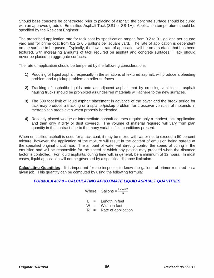
Original: 1/3/1994 66 Revised: 8/15/2017
Should base concrete be constructed prior to placing of asphalt, the concrete surface should be cured with an approved grade of Emulsified Asphalt Tack (SS1 or SS-1H). Application temperature should be specified by the Resident Engineer. The prescribed application rate for tack coat by specification ranges from 0.2 to 0.1 gallons per square yard and for prime coat from 0.2 to 0.5 gallons per square yard. The rate of application is dependent on the surface to be paved. Typically, the lowest rate of application will be on a surface that has been textured, with increasing amounts of tack required on asphalt and concrete surfaces. Tack should never be placed on aggregate surfaces. The rate of application should be tempered by the following considerations:
1) Puddling of liquid asphalt, especially in the striations of textured asphalt, will produce a bleeding problem and a pickup problem on roller surfaces.
2) Tracking of asphaltic liquids onto an adjacent asphalt mat by crossing vehicles or asphalt
hauling trucks should be prohibited as undesired materials will adhere to the new surfaces.
3) The 600 foot limit of liquid asphalt placement in advance of the paver and the break period for tack may produce a tracking or a splatter/pickup problem for crossover vehicles of motorists in metropolitan areas even when properly barricaded.
4) Recently placed wedge or intermediate asphalt courses require only a modest tack application
and then only if dirty or dust covered. The volume of material required will vary from plan quantity in the contract due to the many variable field conditions present.
When emulsified asphalt is used for a tack coat, it may be mixed with water not to exceed a 50 percent mixture; however, the application of the mixture will result in the content of emulsion being spread at the specified original uncut rate. The amount of water will directly control the speed of curing in the emulsion and will be responsible for the speed at which any paving may proceed when the distance factor is controlled. For liquid asphalts, curing time will, in general, be a minimum of 12 hours. In most cases, liquid application will not be governed by a specified distance limitation. Calculating Quantities - It is important for the inspector to know the gallons of primer required on a given job. This quantity can be computed by using the following formula:
FORMULA 407.0 – CALCULATING APROXIMATE LIQUID ASPHALT QUANTITIES
Where: Gallons = L×W×R9
L = Length in feet W = Width in feet R = Rate of application

Original: 1/3/1994 67 Revised: 8/15/2017
408 PAVING OPERATION
408.1 UTILIZING THE VARIOUS SCREED CONTROLS - Automatic screed control for full depth construction will be subject to the following: When placing full depth main line pavement without curb and gutter, and established grade reference will be required to properly establish the subgrade elevation and first lift. For paving conditions of multiple lane widths, the traveling reference may be used subsequent to the initial lane placing. As the other lanes will depend on the placing accuracy of the initial lane (when the traveling reference is uses in this application), care must be taken to ensure the accuracy of the asphalt application vs. the established grade reference. Any variation from the established grade will be justification for disqualification of the use of the traveling reference and required use of the established grade reference for each lane. The established grade reference is intended to provide an accurate longitudinal grade and proper cross slope in the first lift of material so that subsequent lifts may be placed with minimal adjustments in profile grade or cross slope. The idea that errors made in the initial lift can be corrected in the subsequent lifts is inaccurate. Proper inspection to obtain a correct first lift will make the rest of the placing a matter of course. The initial lane placing of the first lift on a roadway without curb and gutter should always be at centerline paving outward to the shoulder. When placing full depth main line pavement with curb and gutter, the established grade reference may be assumed to be the front line of the gutter section provided the curb and gutter section was poured on grade and in the proper alignment. When this is the case, the traveling reference may be used for the first lift placing with only a check at centerline being required to confirm a proper slope. Under these circumstances, the initial lane installation should be adjacent to the gutter line with paving proceeding to centerline. Again, the accuracy of placing of the first lift will control the ease of completion of the paving operation. The remaining layers of base asphalt will be merely reproducing the longitudinal grade and cross slope of the first lift placed. Should a base failure occur or an error exists in the first lift, corrective action is best accomplished by using an established grade reference. If removal of base material is required, be sure that portions of the first lift beyond the removal area are not disturbed or elevated. The reinstalled asphaltic concrete material used to correct a failure should be allowed to properly cool before the next lift is placed. The final lift of asphaltic concrete will be the wearing surface. The wearing surface will be placed without the use of the traveling reference but will take into consideration the established grade reference. The thickness of wearing surface will be adjusted to produce the smoothest possible riding surface which will correspond to the original established grade reference. In many cases, trades will have to be established which will check existing grade against the established grade reference to produce thickness dimensions at centerline for the contractor’s use. On roadways with curb and gutter, the asphalt lift for the wearing surface should be left ¼ to ⅜ inch higher than the matching gutter to allow for compression upon compaction. In flat areas where the wearing surface is placed to the curb face, a 4 foot level should be used to check drainage before any compactive effort is applied to the lift. The contractor should provide the necessary hand labor to lute the asphalt to establish a water line that will drain. The water line must be established before rolling occurs; it is almost impossible to rework compacted asphalt without producing a segregated, open surface. This method applies only to full depth construction with or without curbs.

Original: 1/3/1994 68 Revised: 8/15/2017
408.2 WEDGE COURSE - When the paving involves a wedge course and a wearing surface course, automatic screed control will be required as follows: In areas where the pavement surface is irregular, rutted, wash boarded, or where curves are improperly superelevated, a leveling course will be required. The purpose of a leveling course is to establish a smooth riding surface with the proper cross slope. In these instances, an established grade reference will be the easiest method of grade control. A traveling reference may be used in isolated areas; however, in extensive areas needing correction or in superelevation, the manual override of the automatic system will be required. When a leveling course is to be applied to obtain a constant desired cross slope, the traveling reference is best utilized. In this particular case, the thickness of the leveling course will be a major consideration. Because a uniform slope is being applied to a more or less parabolic surface, placing thickness will vary greatly from centerline to edge line. In order to obtain proper compaction and minimize the amount of asphaltic concrete required, a beginning trial thickness of one inch over the existing roadway high point should be used. The thickness can then be revised as required. Under no circumstance should the screed be allowed to drag the existing surface unless so agreed by your Regional Project Engineer Supervisor. When spot wedging of the surface is required, the traveling reference is best employed. Because of the small areas required to be wedged, featheredging of the asphalt placed will also be required. This featheredging and any handwork on asphalt edges should be accomplished with an asphalt rake or lute designed for use in this application. The method of featheredging involves tapering the lift thickness from full depth to zero in an area of several feet. By raking the material at the edge it is possible to segregate the larger aggregate from the mix, leaving the finer material to be compacted. In so doing, the lift can be tapered to prevent a bump. This practice should be used sparingly and not on the wearing surface as raveling may occur with traffic. When the wedge or leveling course has placed the roadway surface at the proper cross slope, the wearing course may be placed. The wearing course may be applied by using either the traveling reference or the shoe sensor (after the first lane has been applied using the traveling reference). The traveling reference is the preferred method of automatic screed control and may be required for screed widths in excess of one lane each direction. When the paving involves an overlay of the existing surface, a shoe type sensor may be used to place the asphalt material. Here again, manual override of the automatic screed control may be required to produce the best riding surface. For road widths greater than one lane in each direction, a traveling reference may be required. 408.3 MAIN LINE CONSTRUCTION PROCEDURES - The following procedures are accepted as standard operational procedure in this area when placing asphalt: Initial lift thickness for base courses, wearing courses and overlays is obtained by placing either an uncompacted leveled pad of asphalt or lumber of the proper thickness under the screed of the paver. The screed should be placed flat on the supporting surface, and the initial 5 to 10 feet of paving will require handwork to obtain the proper surface with a consistent cross slope and longitudinal grade. Normally, the screed will sink when paving begins until the automatic controls have an opportunity to establish the proposed grade. Adjustment to the screed, which overrides the automatic controls, will require 5 to 10 feet of machine movement to take effect.

Original: 1/3/1994 69 Revised: 8/15/2017
The beginning area of each lane for the length of the paver should be checked by string line to determine the accuracy of the paving. Handwork will be required as necessary to eliminate high and low areas. Once paving has begun, it should be kept on a continuous basis with as few stops as possible. The area where the screed begins to move after each stop should be reviewed for possible handwork required to maintain a uniform surface.
Calculating Quantities - It is important for the inspector to know the approximate tonnage of asphalt required on a given roadway. This quantity can be computed by using the following formula:
FORMULA 408.3 - CALCULATING APROXIMATE ASPHALT TONNAGE
Where: Tons = L×W×D×N18000
W = Width in feet
L = Length in feet
D (For compactive thickness of ½ inch) = 55 D (For compactive thickness of 1 inch) = 110 D (For compactive thickness of 2 inch) = 220 D (For compactive thickness of 3 inch) = 330 D (For compactive thickness of 4 inch) = 440
Type of Material Used
N ("X" & "C" Mix) = 1
N (Non-Skid Trap/Limestone) = 1 N (Non-Skid Slag/Limestone) = 1.12
408.4 BUTT JOINTS - In areas where butt joints have been provided or a solid vertical edge will bound the asphalt pavement, the uncompacted wearing course should be placed ¼ inch to ⅜ inch higher than the solid in-place surface. The solid surface asphalt surface interface may require handwork to assure an even juncture after compaction by the roller. Where butt joints are used, the course should be rolled transversely on the initial pass with the roller's weight equally borne by the solid surface and the asphalt surface. The subsequent roller passes should be longitudinal across the butt joint. Where curb and exposed gutter abutt the wearing course, the initial pass of the roller should bear on the gutter section and the asphalt paving; Joints at the curb and gutter should not be pinched by rolling at the interface surface on the wearing course, as low areas may develop at the front edge of the gutter which will not properly drain. It is acceptable for the pavement wearing surface to be slightly elevated above the gutter section at the interface. 408.5 TRANSITIONAL JOINTS - When no butt joint is provided, a transitional section will be necessary to proceed from the existing surface to the new wearing course. The transitional section will be produced by featheredging the asphaltic material as previously explained. Transitional sections should be a minimum of 5 feet in length to prevent an abrupt elevation change. Transitional sections will also be required where a wedge course is to be stopped short of a bridge. The transitional section should generally be stopped prior to the approach slab or a minimum of 30 feet.

Original: 1/3/1994 70 Revised: 8/15/2017
408.6 CONSTRUCTION JOINTS - At the end of each day's run, a transverse construction joint will be installed. This joint will be made vertical, true to grade and cross slope and densely compacted. Handwork at the joint will be held to a minimum. A hard, full depth edge board held in place will be required when rolling the joint. This will prevent rolling down the edge during compaction. Construction joints will not occur at the same location in succeeding layers but will be offset at least 20 feet from each other. When traffic is to use the asphaltic concrete for a driving surface before the entire project is completed, a paper joint will be installed at the end of each day's run and then removed before the paving is resumed. Paper joints are produced by placing roofers felt or any non-bituminous impregnated paper on the surface in advance of the joint. An approximately 6 foot length of paper will be required for the full width of the lane being placed. The paper should be placed so that ⅔ protrudes past the joint ahead and ⅓ rests on the newly placed asphalt. A full depth header (usually 2" x 4") is placed on the paper at the joint location and the trailing ⅓ of the paper is folded forward over the header. Asphaltic concrete is then placed atop the paper and header. The asphaltic material is transitioned to compensate for the elevation offset (on the paper) and then rolled. This procedure allows for rapid installation and removal and a vertical joint for resumed paving operations. 408.7 LONGITUDINAL JOINTS - Longitudinal joints will be produced while asphalt is being placed. The longitudinal joint to be produced on the outside edges of pavements without abutting cubs or curb and gutter sections will be created by an edging plate so set as to produce a 3 to 1 beveled edge to the surface of the roadway. The remaining longitudinal joints in the driving lanes will be vertical to the surface of the roadway. The remaining longitudinal joints in the driving lanes will be vertical to the surface of the roadway. If necessary, a lute or rake may be used to correct slumped areas. Longitudinal joints are expected to be straight and at the lane line. To produce a tight joint, prime or tack may be applied to the existing surface when adjacent lanes are placed. All such joints should be luted flush. The joint should be so rolled (pinched in) as to produce a level, well compacted, tightly fitted joint. When joints are run over or rounded off, it will be necessary to overlap, lute and handwork the joint to produce a smooth joint that will not separate or hold water. 408.8 COMPACTION REQUIREMENTS - Compaction in asphaltic paving is obtained by using a combination of self-propelled steel wheel rollers and self-propelled pneumatic rollers. Compaction requirements for base asphalt (Type X) are a minimum of 95 percent of the laboratory determined standard, a minimum density of 98 percent for wearing surfaces (Type C and D) and 96 percent for non-skid mixes. Density penalties may be assessed for insufficient compaction or, in some cases, the pavement will be removed and replaced. 408.9 ROLLING - A well-engineered and executed construction job employing the most advanced grading and leveling techniques and the best of materials and workmanship can be cancelled entirely by slipshod methods in rolling and finishing. Because of this, the value of an experienced rolling operator cannot be disputed. A definite rolling pattern should be established to assure a uniformly and correctly compacted mat.
The rolling sequence should be as follows:
1) Breakdown Rolling - Steel wheel rollers are designed to move in a slow, continuous manner with the drive wheel towards the paver. The initial rolling of the pavement will be made as soon as possible after placing by the paver. Rolling will always progress from the low side of superelevated curves toward the higher side. For pavement abutting curbs or curb and gutter sections, the rolling will proceed from the curb or from the edge of gutter toward the centerline (one lane each way). For pavement not abutting curbs or curb and gutter sections, the rolling will proceed from the curb or from the edge of gutter toward the centerline (one lane each way). For pavement not abutting curbs or curb and gutter sections or for additional lanes (two lanes each way or more), rolling will be at the abutting longitudinal joint first and then from the curb side toward centerline. Each pass of the roller should overlap the previous pass by one

Original: 1/3/1994 71 Revised: 8/15/2017
half the width of the drive wheel, and the change of direction at the end of each pass should be made without bringing the roller to a complete stop or spinning the drive wheel on the pavement. Under no circumstance should the roller be stopped and left in place on the hot asphalt. All abutting longitudinal joints should be pinched in by rolling on the previously compacted surface and the edge of the new mat. Any displacement in the asphalt surface caused by the action of the roller will be corrected by handwork in an acceptable manner. Pavement edges which are displaced by the rolling process will be immediately corrected by hand methods as required. Hand tamping of inlet throats or any inaccessible area, will be performed as soon as is possible after placing by the paver. Transverse rolling of the pavement will be required to remove high spots in the pavement at transverse construction joints and in intersections. Normally, rolling will be performed in straight lines parallel to centerline; however, rolling in intersections should follow the curb rounding or direction of travel of the automobile. Where drainage may be a problem, a check of the water line should be made after the initial rolling, and any hand tamping necessary to provide flow should be performed immediately. The termination of each pass by the roller should be staggered to prevent irregularities.
2) Compacting - After completion of the initial rolling, the pneumatic roller may be placed on the
new lift. The purpose of the pneumatic roller is to produce compaction in the freshly placed asphalt. In order to obtain maximum compaction without cracking or marking the pavement, rolling by the pneumatic roller must be closely controlled. Generally the asphaltic concrete must be between 275°F and 300°F to obtain maximum compaction. The best indication of proper rolling is to be able to place the pneumatic roller on the layer so that the surface is indented without cracks appearing in the surface. The newly placed lift should be rolled in a manner similar to the steel wheel roller method with emphasis placed on a uniform speed and equalized coverage of the roadway. Should marring or cracking of the pavement occur, the rolling should be discontinued temporarily. In critical temperature periods, ambient temperature, wind velocity and surface temperature will be major factors in determining when to roll with the pneumatic roller. Because of the narrow temperature range which restricts the ability to obtain the required compaction, this sequence of rolling will demand the most intense inspection.
3) Final Rolling - After the pneumatic rolling sequence is completed, the final rolling, with a steel
wheel roller, of the pavement may be commenced. As previously emphasized, temperature of the pavement will again be the controlling factor. The purpose of the final rolling is to remove all marks or marring of the surface and leave a uniform, compacted, impervious wearing layer. Temperature control is critical as a too hot surface will not properly seal and lose compaction and a too cold surface will have an open, rough, marred appearance. As a general rule of thumb, the asphalt should be sufficiently hot so as to produce steam from the moistened roller surface (220°F to 250°F). Rolling should be continued until all surface marks are removed. Upon completion of the rolling operations, pavement may be opened to traffic when the wearing course has cooled to the ambient temperature or until marring of the surface will not occur.
409 SEAL COAT 409.1 AGGREGATE SPREADER - The aggregate spreader is a self-propelled mechanical spreading unit which is capable of measuring and distributing rock chips for use in seal coating operations. The spreader is designed with a rear mounted hopper of variable capacity which is filled by direct discharge from a dump truck. The chips are conveyed to the discharge gates by means of a conveyor belt which is controllable by manual override or by automatic sensors mounted in the discharge gate area which monitors the volume of chips present at any time. The discharge gates vary from 6 to 12 inches in size with the smaller gates mounted on the outside. Each gate is independently adjustable as to the volume of aggregate chips being discharged.
Original: 1/3/1994 72 Revised: 8/15/2017
Inspection is limited to checking the gates for the proper amount of chips being discharged and the automatic load capacity sensor's operation. There are no automatic alignment or elevation controls. The hopper should also be periodically checked for deleterious material often present in stockpiled chips. Seal coats are normally used in shoulder areas adjacent to main line pavement areas and for wearing surfaces on existing concrete and asphaltic concrete streets. At a minimum, the following equipment will be required to place a seal coated surface: power distributer, rotary broom, 5 to 8 ton pneumatic roller and a self-propelled chip spreader. Seal coats may not be placed when the ambient temperature or surface temperature is below 70°F (unless authorized by the Director), when the surface is wet or frozen, or when weather conditions prevent proper handling of the material required. In addition, the surface to be covered by the seal coat must be swept and free of debris. The application of the bituminous material will be performed by a pressure distributor. The asphaltic material will be heated to a temperature specified by the Resident Engineer and within the range cited in the Specifications with the exception of asphalt cement which will be between 315°F and 350°F. The inspection of the application of bituminous material will include checking for cleanliness of the surface to be covered, uniform application of material, temperature of material being applied and traffic control. The surface must be cleaned and free from oil or grease concentrations. For shoulders, the rock grade must be thoroughly and completely compacted and leveled to the proposed grade. The moisture content restrictions for Type 1 aggregate will apply as for the asphaltic products. The grade of the bituminous material will be specified in the contract. The grade of the emulsified asphalt will be designated by the Specifications and will depend on the type of cover aggregate to be specified. The application rate will be established for asphalt cement are: 1.25 gallons RC-3000 equal 1 gallon asphalt cement, 1.25 gallons MC-3000 equal 1 gallon asphalt cement, 1.82 gallons RS1 equal 1 gallon asphalt cement, 1.67 gallons CRS1 equal 1 gallon asphalt cement, 1.54 gallons CRS2 equal 1 gallon asphalt cement. Normally, the straight application rate of base bituminous will range from 0.24 to 0.30 gallons per square yard, depending on the condition of the pavement surface. The material will be applied in a uniform, continuous spread without gaps or overlaps. The bituminous application will completely cover one lane to the lane line and will be placed at a speed which will not exceed that of the chip spreader capacity to place the chips. Placing of the aggregate chips will commence as soon as the bituminous material is placed and will continue at a rate equal to the bituminous placing rate. Normally, the cover aggregate will be placed within 2 minutes of the bituminous material. The cover aggregate will be uniformly spread by a mechanical spreader at a controlled rate established by the Resident Engineer (if not stated in the Specifications) varying from 18 to 25 pounds per square yard. Immediately after spreading, the surface will receive two complete passes by the pneumatic roller. After the embedded chips have become firmly set in the asphalt binder material, the surface will be lightly swept. The sweeping operation should take place the day following the application of the aggregate. The contractor is required to maintain the new surface for up to 4 days. Any areas of bleeding bituminous material will be rechipped and rolled as needed. The entire surface will be swept free of chips by the contractor as part of the contract. Inspection of the operation will be mainly concerned with the placing rate of chips, the condition of the chips and the degree of embedding. The chips should be surface dry for all applications except asphaltic emulsions when surface moisture is allowable and occasionally preferred (5 percent maximum by weight). The chips should be embedded in the bituminous material to a depth of ½ to ⅔ the size of the chip. Raveling will occur with too light an application of bituminous material, and excessive amounts will result in bleeding on the surface. The application rate must be field controlled by the Resident Engineer as work progresses. Traffic control during the placing operation will entail closing one lane to traffic and keeping it closed until all rolling is completed.

Original: 1/3/1994 73 Revised: 8/15/2017
The contractor will provide a pilot vehicle to control speed in the project area to a maximum of 20 mph for at least 2 hours after rolling is completed. When double seal coats are specified, they will be placed in a similar manner with the following exceptions: the first seal coat will be placed full width before any part of the second seal coat is placed; the second seal coat will be placed during the same day as the first seal coat, and the placing of the first seal coat will be limited as necessary to ensure compliance.
410 PAVEMENT SURFACER - In recent years, the pavement surfacer (also called Rotomill, Cold Planer) has been used with increasing regularity. The pavement surfacer has the advantage of being able to remove the surface irregularities in concrete and asphalt pavement and leave a textured, skid resistant surface. Two types of surfacer are in common use. The first is a small unit, non-propelled and usually attached to a motor patrol in place of the blade. The unit is hydraulically powered and is designed for use in small, isolated areas. The surfacer is incapable of loading reclaimable aggregate and is not used for most main line areas. The other type of pavement surfacer is self-propelled, either track mounted or mounted on pneumatic tires, equipped with automatic grade and cross slope control sensors and an integral loading, dust control and aggregate reclamation system. Inspection of the equipment includes the following:
1) The surfacer is equipped with a milling cutter head composed of carbide tipped teeth affixed to individual discs. The discs are mounted so as to provide a staggered cutting wheel with teeth on 6 inch centers around the circumferential surface of the milling head. The length of the teeth should be monitored for conformity around the milling head. Replacement teeth must be adjusted to conform in height to existing teeth.
2) The cutter head height controls the depth of cut performed by the machine. The depth of cut is
controlled by an automatic system which provides both profile grade and gross slope sensors. The profile grade is the most significant grade for material removal with the cross slopes being controlled as a constant grade set by the operator. The profile grade will normally be established by a 30 foot ski pole mounted to run adjacent to the machine which will provide longitudinal grade control in each driving lane. In certain areas, a string line may be required to obtain the grade required. In either case, the same procedures for inspection discussed for asphalt pavers will apply. A manual override of the automatic system must be functional at all times for grade adjustment.
3) The surfacer loading and reclamation system must be functional and in operation at all times. A
back up system must also be provided in case of breakdown. The system should remove and load all aggregate milled from the surface.
Inspection of pavement surfacing and texturing will mainly involve grade control, removal of all loose material and the smoothness of the surface obtained. The grade control will be set and controlled by a traveling reference used to guide the machine. The height of the cutter head will be controlled by the operator and will be a stated amount from the plan or as established by the Resident Engineer when deemed necessary. In areas of washboarded, depressed, elevated, or extremely irregular pavement sections, an independent grade control may be required. When necessary, the Resident Engineer will enumerate these areas to the contractor who will establish the independent grade control and maintain said grade in a satisfactory manner until the final desired grade is obtained.

Original: 1/3/1994 74 Revised: 8/15/2017
When removal of material will leave a vertical edge at the lane line in excess of 1¼ inches at centerline or 2 inches at the shoulder, the longitudinal face will be sloped so as not to present a hazard to traffic. Transverse beginning and ending joints will also be transitioned to provide a smooth ride. All loose material will be cleaned from the pavement on a concurrent basis and removed from the project. Before any texturing is performed, a dust control system must be in place and in working order on the equipment. Before any pavement is opened to traffic, it must be cleared or swept to remove any residual cuttings and dust. The contractor will be responsible for removal of all cuttings and debris from the project. The smoothness of the completed surface will be to within ¼ inch in 10 feet, and adjacent lanes will be within ⅛ inch of the same elevation (plus or minus) at the adjoining edges. 411 TESTING - In order to properly monitor the thickness and density of the asphaltic material being placed on the project, a variety of testing procedures will be implemented by personnel from the Materials Testing Laboratory. It will be necessary to schedule the required personnel and equipment to obtain the testing information needed on a daily basis (24-hour notice). Thickness and compaction results will be provided on the project, as paving proceeds, by personnel from the Materials Testing Laboratory utilizing the nuclear density gauge. Testing will normally be in 2,000 foot increments per lane will a series of test readings being taken in a small area to obtain an average result. In addition, individual or small groups of readings may be taken to obtain or modify the rolling pattern in use or provide information on air voids necessary to modify the mix design. It is often necessary to monitor compaction behind each roller to determine over rolling or under rolling which, when combined with the temperature of the asphalt mat, will provide the best roller pattern and time available to obtain maximum compaction. The contractor’s representative must be kept abreast of the results so obtained and should take appropriate action to rectify any problems or compaction deficiencies. Penalty payments will be assessed for insufficient compaction, and continuous compaction failure will be considered cause for a Stop Order and possible removal of the asphaltic material at the contractor’s cost. A graduated scale of penalty payments will be assessed in 500 foot intervals when encountered. These compaction results will be obtained by core sample taken from the newly placed asphalt mat. Penalties for inadequate compaction will always be based on results obtained from cored samples. Nuclear density testing will not be required on wedge courses unless a nominal thickness is specified. Base asphalt will, in general, be spot checked with the nuclear density gauge and cored to determine thickness and compaction. Surface smoothness will be tested by using a 10 foot straightedge parallel to centerline in each wheel lane. A maximum deviation of ⅛ inch in 10 feet will be allowed on the top layer of asphaltic material. At transverse construction joints, a maximum of ¼ inch in 10 feet will be the maximum deviation. Corrective action for non-compliance with the deviations established may include grinding and/or removal and replacement.
Original: 1/3/1994 75 Revised: 8/15/2017
412 CHECK LIST - FLEXIBLE PAVEMENT
COMPACTION OF FOUNDATION Have all courses of the foundation been compacted to required density?
OLD ASPHALT PAVEMENT Potholes patched?
Necessary patches made?
Loose material and "fat" patches removed?
Depressions filled and compacted?
Fog seal used on surface that has deteriorated from oxidation?
Emulsified asphalt slurry seal applied on old surfaces with extensive cracking?
RIGID TYPE PAVEMENT Pavement undersealed where necessary?
Pre-molded joint material and crack filler cleaned out?
All "fat" patches removed?
Severely broken pavement removed and patched?
Depressions filled and compacted?
INCIDENTAL TOOLS Incidental tools comply with Specifications?
Necessary tools on the job before work begins?
ENGINEER AND CONTRACTOR Engineer and his inspectors have held a preliminary conference with the appropriate
contractor personnel?
Continuity of operations planned?
Determined number of pavers to be used?
Determined number and type of rollers to be used?
Determined number of trucks to be used?
Width of spread in successive layers planned?
Is it understood who is to issue and who is to receive instructions?
Determined weighing procedure and number of load tickets to be prepared?
Procedures for investigation of mix agreed upon?
Method of handling traffic control established?
PREPARATION OF SURFACE All surfaces that will come into contact with the asphalt mix cleaned and coated with
asphalt?
Uniform tack coat of correct quantity applied?

Original: 1/3/1994 76 Revised: 8/15/2017
ASPHALT DISTRIBUTER Asphalt distributer complies with Specifications?
Heaters and pump in good working condition?
All gauges and measuring devices such as bitumeter, tachometer and measuring stick calibrated?
Spray bars and nozzles unclogged and set for proper application of asphalt?
HAULING EQUIPMENT Truck beds smooth and free from holes and depressions?
Trucks comply with Specifications?
Trucks equipped with properly attached tarpaulins?
For cold weather or long hauls - truck beds insulated?
Do trucks (when unloading) and paver operate together without interference?
Method of coating of contact surfaces of truck beds agreed upon?
Truck bed to be raised slowly to prevent segregation?
PAVER Paver comply with Specifications?
Governor on engine operating properly?
Slat feeders, hopper gates and spreader screws in good condition and adjustment?
Crawlers adjusted properly?
Pneumatic tires contain correct and uniform air pressure?
Screed heater working properly?
Tamper bars free of excessive wear?
Tamper bars correctly adjusted for stroke?
Tamper bars correctly adjusted for clearance between the back of the bar and the nose of the screed plate?
Surfaces of the screed plates true and in good condition?
Mat thickness and crown controls in good condition and adjustment?
Screed vibrators in good condition and adjustment?
Oscillating screed in proper position with respect to the vibrating compactor?
Automatic screed control in adjustment and correct sensor attached?
SPREADING Required number of pavers on job?
Mix of uniform texture?
General appearance of mix satisfactory?
Temperature of the mix uniform and satisfactory?
Mix satisfies the spreading requirements?

Original: 1/3/1994 77 Revised: 8/15/2017
Proper paver speed determined?
Surface tolerance checked and adhered to?
Depth of spread checked frequently?
Daily spread checked?
ROLLING Required number of rollers on the job?
Proper rolling procedure being followed?
Proper rolling pattern being followed?
Joints and edges being rolled properly?
MISCELLANEOUS All surface irregularities properly corrected?
Efficient control of traffic maintained?
Sufficient samples taken?
Are samples representative?
Assistant Inspectors properly instructed?
Inspection duties properly apportioned among assistants?
Records completed and up-to-date?
Safety measures observed?
Final cleanup and inspection made?
Rejected material tickets marked "Rejected" with reason and copies retained?

Original: 1/3/1994 78 Revised: 8/15/2017
SECTION 500 RIGID PAVEMENT 501 CONSTRUCTION STAKING - Paving grades will be set on offset stakes determined by the method of paving employed. The contractor should provide the offset distance required prior to any staking by the Survey Party. In general, the County will establish pavement grades, radius points, warp grades and flow line grades for gutters and curb and gutter sections. In all cases, a cut or fill stake will be provided to determine finished pavement grade or water line grades. "Bluetops" (hubs driven to grade) will not be provided by the Survey Party. Pavement grades will be established at 50 foot intermediate and 100 foot stations. Warp grades will be given at points on the radius as specified on the plans. Grades will also be given at radius points and, when required, at 25 foot intervals for sharp vertical curves or in areas where drainage is critical. Upon completion of rough grading by the contractor, areas of roadway should be staked to facilitate fine grading, placing of aggregate base courses or asphaltic concrete bases and paving forms. The contractor should request these areas be staked at least 24 hours prior to the expected work in preparation of the subgrade. The Party Chief should verify the proposed centerline profile grade and stake the roadway pavement in accordance with these grades and the typical section applicable as shown in the Construction Plans. The stake, as shown in Illustration 501A, would indicate the tack point on the hub is 4 feet from the edge of pavement (perpendicular on tangent, radially on a curve) at Station 28+00-left, and a cut of 0.33 feet would be required to reach finish pavement grade (measured level from the paving hub). Elevation will be taken from the highest point of the paving hub, not the tack point. Radius points are given to indicate the central point of a circle or circular arc employed to connect two tangent lines. Radius points are commonly placed at street intersections and to denote radii for drive approaches or sidewalks. The radius stake is accompanied by a hub containing a tack point to denote the center point. All radius hubs should show the distance of the radius from the tack point to the edge of pavement or back of curb as shown in Illustration 501B.
ILLUSTRATION 501 – TYPICAL PAVEMENT & RADIUS STAKES
While radius points for pavements are staked to denote edge of pavement or back of curb, care should be taken because radius points for medians or islands are staked and also marked to face of curb. Warp grades are provided on the plan sheets for drainage at intersection rounding's. These grades are mathematically interpolated and may need adjustment to maintain a constant slope in the water line at intersection rounding's. The staking required for warp grades is similar to the stakes as set for finish paving grades. An offset stake with cut or fill to water line and tacked hub is required at the staked spacing show on the plans.

Original: 1/3/1994 79 Revised: 8/15/2017
502 SLIP FORM PAVING - When slip form paving methods are employed for main line paving, inspection will involve the following items:
1) Subgrade Preparation - Subgrade preparation will be as described in the subgrade preparation established in Section 200. As previously explained, accuracy in establishing elevation and alignment control is dependent on the string line and the care taken in establishing it on the proper line and grade. The finished product in slip form paving is dependent on the string line and the accuracy with which it is set in place; therefore, all inspections should center around its placement and the reaction of the equipment’s guidance system in relationship to the established grade and alignment control.
2) Paving Procedure - The inspection will in large part be as described for stationary form paving
with a great deal of inspection emphasis placed on a consistent slump concrete. The paving accessory check will be the same with additional inspection emphasis focused on placing of the keyway and slumping at the edge of pavement. The finishing requirements will be the same in nature, and the straightedging of the pavement will be the major item of consideration. The requirements for surface texture, curing and sawing are discussed later in this section.
Regardless of the method of paving, weather must be considered on all main line pavement pours. In case of rain, each pavement pour will require a provision for covering pavement which has not reached its initial set. The contractor must have on hand at all times adequate waterproof sheeting to cover the full width of the new pavement for the length required. When required, the sheeting will be placed until the rain is over and then the surface of the pavement refloated and texturized as needed. In locations where storm water from higher elevations (pavement or other) is likely to run over the newly placed concrete, steps must be taken to deflect this water so it will not pass over this fresh concrete. Sandbags, lumber, plastic sheeting, etc. may be used as long as the do the job. It is best to have a plan and the proper material available at the high end of the pour. A surprising amount of water will flood the area after several minutes of rain. It is solely the contractor’s responsibility to assess the risk in paving when the possibility of rain exists and to provide the necessary precautions. 503 FORMS - When the forms are set for the conventional rail paving methods, the exact subgrade elevation must be obtained. Prior to utilizing the subgrade planer, the side forms must be secured and the aggregate surface under the form tamped to prevent settlement. A one foot width beyond the edge of pavement is provided in the aggregate plan quantities to allow for a stable compacted base for the side forms. In order to use the subgrade planer, the form line must be established to the exact finish grade of the proposed pavement and to the exact alignment. This is possible by the use of the offset distance and elevation information provided on the paving grade stakes. Normally, a graded string line is placed on line and graded, and the forms are set to this string line. After the string line is placed, a visual inspection check for alignment and elevation should be made by eye as well as by a level and ruler. The paving forms should be securely held in place by staking pins and should be interlocked before the subgrade planer is mounted on the forms. A minimum of 3 staking pins per 10 foot form should be used to hold it firmly in place. The subgrade planer used for conventional paving is mounted on wheels that ride on the side forms and is drawn by a tractor or high lift. The cutting edge is mounted to a transverse beam which is adjustable for depth below the top form. The cutting edge is composed of individually adjustable plates which should be checked for alignment by string line before each use. The subgrade planer is designed to remove small amounts of aggregate on each pass; therefore, the grade must be close to the proper grade before the subgrade planer can work effectively. The subgrade planer has the ability to bring the aggregate grade to within ⅛ inch of the proper elevation by making repeated passes over the compacted aggregate surface. A check of the required aggregate subgrade elevation may be made at any point on the roadway by pulling a taut string line from top of form and measuring down the

Original: 1/3/1994 80 Revised: 8/15/2017
thickness of the proposed pavement. This depth check should be recorded in the Subgrade Book. A check template may also be used to indicate the accuracy of the grading operation. Due to the penalty provisions provided in the Specifications, the aggregate subgrade must be established to an elevation no higher than ⅛ inch from the proper grade, the proper grade being the profile pavement grade minus the proposed pavement thickness. This requirement applies for the full width of the paving section - no compensating section can be allowed for the aggregate subgrade. Side forms serve two purposes, both of which are extremely important. First, they confine the wet concrete so that it is true to line and grade and has vertical edges or properly formed tongue-and-groove joints when finished. Second, they support the heavy construction equipment without settlement or lateral displacement since irregularities in forming, whether due to poor placement or to poor forms, are reflected in the riding qualities of the pavement. The side forms must meet the following requirements:
1) Paving forms are to be of metal with a base width equal to the height of the form except 10 inch forms may have 9 inch bases.
2) The form shall be straight with no more than ⅛ inch in 10 feet deviation from a straight plane on
the top or ¼ inch in 10 feet deviation on the face of the form. Forms should be checked by string line and rejected forms clearly marked with paint or other permanent marking substance.
3) When "built up" forms are allowed, only 20 percent of the form height may be wood. The wood
applied to the form must be at the base and must be wide enough to afford uniform bearing for the entire form. No "floating" or suspended forms with open spaces underneath will be allowed. Crushed stone pushed underneath the forms will not be acceptable. Forms must be full height and resting on compacted subgrade.
4) The form should be free of built up concrete, especially on the top finishing edge. The forms
should have attached pin pockets with pin locking devices located in at least three places per form. Each form should have an interlocking device at each end of the form to provide a positive means of joining the form line at the joints to provide a neat, tight joint. Bends or wrinkles in the end or wall of a side form are cause for rejection of the form. Wood forms for pieces less than standard form length will be kept to a minimum.
5) Pins for holding forms in place should be of sufficient diameter to be locked in the pin pocket by
the tapered locking device and of such length to prevent movement or overturning of the form. Pins should always be driven below the top of the form to allow clearance of the paving equipment wheels. Special attention should be made when driving pins at or near underground utilities to prevent damage to the utility or service lines.
6) Forms to be set in a curve (circular or spiral) will be straight steel forms of 10 feet or less for
curves of 200 feet radius or greater. Straight steel forms of 5 foot length may be used on curves of 100 feet or greater radius. Wood or steel forms may be used on curves of less than 200 feet radius with the exception that wood forms may not be used to support a mechanical paving train. Usually, straight steel forms are practical if the pavement is topped with dowel on curb. The back of curb is formed with wood and hides the broken form line of the steel forms.
504 PAVING ACCESSORIES - When the forms are properly set and the prepared subgrade is at the proper elevation, paving accessories will be placed within the form line.
504.1 KEYWAY - Keyway is used to provide a longitudinal joint at the edge of pavement where curb and gutter are to be poured. It also is used to provide a slip joint between adjacent lanes. The keyway acts to produce a barrier to vertical separation and a mechanism for expansion movement in the pavement.

Original: 1/3/1994 81 Revised: 8/15/2017
504.2 BENT BARS - Bent bars are often used in conjunction with the keyway, especially where a change in grade of the finished surface is involved. Bent bars are usually #5 deformed reinforcing steel bars cut in 30 inch lengths and bent at a 90 degree angle to allow placement of one leg within the keyway and the other leg to protrude into the pavement through the pre-drilled keyway. Bent bars are intended to prevent vertical or transverse displacement of the adjoining pavement surfaces on different profile grades. In general, all pavement should be held together with bars to prevent cracking because of movement due to expansion. When keyway and bent bars are used as a unit, care should be taken to ensure that the keyway is wedged tightly against the side form and that the bent bar remains inside the keyway during the pavement pour. The depth of the keyway in the pavement is controlled by support legs which come in variable heights. A minimum clearance of 2¼ inches should be maintained above the keyway. The bent bars are supported by staking pins and should have a minimum of 3¼ inches of cover above the top of the rod. Staking pins without supports are also used to hold the keyway tightly against the side form. The proper clearance on these items must also be maintained. In pavement sections where an existing keyway or keyway and bent bars have been previously included, care should be taken to completely remove any deleterious material or concrete from the keyway. The keyway should always be washed clean before and concrete is placed adjacent to it. 504.3 CONTRACTION JOINTS - Contraction joints in concrete are made either by sawing and cracking of the pavement or by using a grooving tool to form a joint that controls the cracking of the pavement. In either of the above cases, a load transfer device is placed on the subgrade for inclusion in the pavement. Load transfer devices are of two types, differing only in the method of bar support. Type A load transfer devices have longitudinal supports of 1 inch diameter (1¼ inch dowel bars required for 9 inch and 10 inch thick pavement) x 18 inch dowel bars. Type B load transfer devices have transverse bar supports at each 1 inch diameter x 18 inch dowel bar. Each bar within the devices will have a free and fixed end. The dowel assembly is so designed as to make the fixed and free ends of dowels alternate for the length of the assembly. Wire support stirrups maintain the rigidity of the assembly until ready for paving. It will be necessary to cut the wire braces after the dowel assembly has been installed and staked. The load transfer device should be designed so as to place the centerline of the dowel bars at the required height above subgrade. Unless otherwise shown on the Construction Plans, contraction joints will be placed at a maximum of 20 feet in non-reinforced pavement and will require a sawed joint to produce cracking. When possible, contraction joints should be placed at the centerline and at radius points of intersecting streets and driveway approaches, away from inlet sumps and to intersect manholes in the pavement. The load transfer device must rest on the top of the prepared subgrade and must be staked in place with 6 pins per assembly to prevent movement as concrete is placed. The staking pins used to hold the load transfer device in place should be driven full depth into the subgrade and should secure the bottom of the dowel support assembly. The dowel assemblies should be placed on the subgrade with a minimum of 6 inches clearance from the side form to the centerline of the first load transfer dowel. The location of the dowel assemblies will be established by measurement on centerline for spacing determination with all load transfer devices set at 90 degrees to the curb line form for tangent section and at curves to produce a radial line. The form line will be so marked as to indicate the center of the load transfer device for sawing following the paving operation. When the dowel assembly is in place, the free end of each dowel will be completely greased around the circumference for one-half of its length plus two inches with an approved grease, usually a lithium-base type containing graphite, and the supporting stirrups cut to allow free movement of the load transfer dowels.

Original: 1/3/1994 82 Revised: 8/15/2017
504.4 EXPANSION JOINTS - Expansion joints will be placed at areas designated on the plans, at all bridges and box culverts (where the top of the box is used as pavement) and in conjunction with bridge approach slabs. County expansion joints are either 2 inch thick bituminous treated expansion material (Type A2) or 1 inch thick bituminous treated material (Type A or AA). The joints will be full width and full depth of the pavement. The top of expansion joints will be filled with sealer as shown in the Standard Drawings. Expansion joints will be installed as shown in the Standard Drawings of the Construction Plans. 504.5 CONSTRUCTION JOINTS - Construction joints are used to stop a pavement pour at a location other than at a normally designated expansion or contraction joint. Construction joints can only be made at an established expansion or contraction joint or at a distance of not less than ten feet from these joints. Construction joints will utilize a header set so as to provide a bulkhead at the desired location. The header must be full depth and full width. A keyway with bent bars should be attached to the header for the full width of the pavement at a construction joint. Care must always be exercised at a construction joint to provide a smooth, true plane surface at the joint and at the adjoining pour after the header is removed. The header should be set by string line and checked both longitudinally and transversely with a straightedge after finishing operations are completed. 504.6 OTHER APPURTENANCES - Other appurtenances on the subgrade will also include:
1) Straight reinforcing steel bars supported by staking pins or paving chairs to create a Type B or Type F joint for longitudinal contraction joints.
2) False forms in the pavement for entrance connections where integral curb is used at the
edge of pavement. Usually a 6 inch wide box-out is formed for the length of the drive approach, radius point to radius point, with a keyway and bent bars provided for future connections.
3) Box-outs for paving at manholes. A full depth square, one foot wider than the outside flange
of the manhole frame unit, should be formed with a paving contraction joint established at the points of the square if possible. Expansion material should be placed around the perimeter of the box-out when the square is poured.
4) Throw-outs for ramps, left turn lanes and pavement widenings. Throw-outs or turn-outs from
main line pavement will require a two foot widening in a distance of 20 feet. The throw-out is required to prevent cracking and slab displacement on a narrow, tapered piece of pavement in a widening section which begins at a point and increases in width at a uniform rate. A throw-out will require a keyway and bent bars along the roadway fence and at the end form.
504.7 DOWEL BARS FOR CURB - Dowel bars for "doweled on curb" must be placed at the proper depth and spacing while the concrete is still plastic. The bars should not be driven in the concrete with a hammer after the concrete has attained its initial set. These bars are typically #4 bars placed on 24 inch centers with a length of 3 inches less than the pavement thickness plus curb height.
505 JOINT DETAILS - The joint spacing, including the required type of joint at each location, and the joint details can be found in the Standard Drawings. These standards are included in the Construction Plans. If this sheet is missing from the plans, these details are also available in the Design Criteria Book.

Original: 1/3/1994 83 Revised: 8/15/2017
506 CONCRETE PAVING EQUIPMENT - Concrete paving equipment is of two types, that which rides on stationary side forms and that which rides on the prepared base (slip form). The purpose of all mechanical paving equipment is to consolidate the pavement mass, to provide a finished surface at the proposed cross sectional template and to obtain the desired smoothness. Because of the variety of machine manufacturers and the various machine modifications possible, this section will deal with general inspection procedures and methods.
506.1 VIBRATORY SCREED - When hand finishing methods as defined in the Specifications are applicable, a vibratory screed may be used to finish pavement. The vibratory screed is basically a lightweight, non-selfpropelled finishing machine. The older versions of this machine are made with a 2 x 8 through 2 x 12 framework of wood with angle iron attached to the bottom edge of two parallel members to form a non-oscillating screed system. The machine is further equipped with an offset weight vibratory system powered by a small gasoline engine mounted directly to the framework. The entire framework is either cable drawn or pulled forward by workmen. The newer vibratory screeds are a lightweight, cable drawn, space frame truss. The screeds are parallel angle iron running the length of the interconnecting truss sections. These truss sections are jointed by adjustable threaded connectors which allow each section to be set at a specified cross slope. Vibration is obtained either by a gasoline powered offset weight vibratory system or by a series of pneumatic cylinders mounted directly to the truss and powered by compressed air.
Inspection of the vibratory screed will include the following:
1) The vibratory screed should be ling enough to allow a minimum of one foot of screed to ride
on the side rails or adjacent pavement.
2) The screeds should be adjusted to the desired cross slope by use of a taut sting line applied to each screed. When a crown or break in cross slope is to be placed in the screed, the screed should first be made straight and the machine set in place on the forms. The crown or break in grade should then be set in the machine while supporting its total weight on the forms.
3) The vibration system should be checked to make sure all components are in working order
and that a minimum frequency of 3600 impulses per minute is maintained. When pneumatic cylinders are used to provide vibration, an occasional check of each cylinder will be necessary in order to prevent sticking of the piston. Over vibration of the surface is to be avoided, and vibrations should be allowed only while the machine is in motion.
4) Consolidation and strike off of the concrete will be done by labor forces in advance of the
vibratory screed. Consolidation should be performed by hand held immersion type vibrators with a minimum frequency of 4500 impulses per minute. The strike off in advance of the vibratory screed should leave enough concrete to allow both front and back screeds to carry sufficient concrete to fill in all depressed areas. Occasional filling with fresh concrete between the screeds will be necessary to accomplish this.
5) A metal straightedge and string line should be used at varying intervals behind the screeds
to check for surface smoothness and desired cross slope. Because of the lightweight nature of the machine, it will tend to ride up over excessive concrete in the form line. When this occurs, the paving operation must be halted and the vibratory screed moved back beyond the bad area and rerun over the area until the proper cross sectional area is obtained.
6) When the vibratory screed is run partially or totally on the adjacent pavement, care must be
taken to match the existing edges. Care must also be taken to clean the adjacent pavement to prevent the screed riding up on the rock or debris. The direct application of weight on the outside ends of the screed is desirable to prevent these problems.

Original: 1/3/1994 84 Revised: 8/15/2017
7) Because these machines are cable drawn, care must be taken to keep the cable extended as far as possible in front of the machine to prevent tipping forward of the screeds due to too great an inclination angle of the pickup cable. The machine should be drawn forward equally on each side to keep the machine as perpendicular to the forms as possible.
8) In superelevated areas, the machine will have a tendency to migrate to the low side of the
formed area. Care must be taken to prevent the machine from slipping from the forms in these areas. Concrete may also have a tendency to migrate to the low side and this must be avoided or corrected immediately.
506.2 RAIL FINISHING MACHINE - This type of finishing machine is self-propelled and must be equipped with two oscillating-type transverse screeds. Each screed is composed of self-adjustable incremental plates or enclosed sections. These sections or plates can be adjusted to form a straight-edge, crown or other profile shape. The finishing machine should also contain vibrators. The following inspection procedure should be utilized prior to paving with the finishing machine:
1) Vibrators should be checked for frequency of impulses, side form clearance, depth of penetration, uniformity of vibration by area and use of vibrators only when paving train is in motion.
2) The alignment of the two oscillating screeds must be checked prior to any paving being
performed. The alignment should also be checked each time the finishing machine is moved from one paving site to another on the same project. Before the screeds can be set, all concrete debris must be removed from the screed and adjusting devices. The alignment can be accurately checked only when the machine is mounted on the forms.
3) The screeds should be checked independently and in the following manner:
a) Place several thicknesses of lumber (2" x 2" or surveying lath) on the side forms, being sure and equal height is used on each side. Run a string line under the back edge of the screed and pull very taut, lower the screed onto the wood on the side forms. Be sure the full weight of the screed rests on the wooden supports.
b) Lower or raise each incremental plate or section until the proper typical section is
obtained. Generally, all plates should be adjusted to a point above the string line and then adjusted down to the proper alignment. When adjustment involves a major movement of the plate (+½ inch), the plate should be tapped with a 2 pound hammer to ensure that the plate is not in a bind or blocked by concrete.
c) The oscillation of each screed should be checked for freedom of movement. The arms
should be straight, well-greased and unimpeded by any concrete or debris. The oscillation of each screed should carry the end well past the form line without making the screed end opposite enter past the outside form line edge. If a shoe is attached to the end of the screed, care should be taken to mount the bottom of the shoe so as to pass over the top of the form without snagging.
d) The elevation of the front screed should be such as to allow approximately ¼ inch of
material to pass to the back screed at all times. The back screed will be set exactly on grade. Concrete should be present in the form of a small roll in front of both screeds at all times to fill any depressions in the pavement surface. Should either screed lose the concrete in front of the screed edge, fresh concrete must immediately be placed or the finishing machine stopped, backed up and concrete added to obtain the proper section.

Original: 1/3/1994 85 Revised: 8/15/2017
4) The wheels on the carriage of the finishing machine should be checked for alignment as stated in the spreader section. The wheels should also be checked for contact with the form at all times. Excessive amounts of concrete in front of the screeds may cause the machine to ride up, or if excess concrete falls over the form line, the wheels may bind up or ride up.
5) The final check on the accuracy of the finishing machine in providing the desired product will
be with a 10 foot wide manual straightedge applied to the finished surface of the pavement. A cement mason should check the screeds performance as soon as possible once paving has commenced. The straightedge should be drawn across the pavement surface, and any repetitive error in surface finish should be corrected by adjusting the screed plate. A constant check with the manual straightedge is required to obtain a quality pavement surface. A string line may also be used to obtain the same check for accuracy of the screed alignment.
506.3 SUBGRADE PLANER - Often the first machine involved in a slip form paving operation is the subgrade planer. This machine is self-propelled, track mounted and designed to cut the aggregate or dirt subgrade for the paving operation. As this machine is designed to cut the subgrade, it will also be necessary to make the subgrade wider than required to allow room for the travel of the slip form equipment. Excess aggregate material from the subgrading process may be reused provided proper compaction is obtained. As with all slip form equipment, the major area of inspection is the contact surface of the alignment and elevation sensor with the graded string line. If both front and rear sensors are parallel and in contact with the string line, the grade should be exact and require only supplemental check by transverse sting line across the grade. 506.4 CONCRETE SPREADER - The next piece of equipment of the slip form paving train is the concrete spreader. The spreader usually contains a conveyor belt used to place the concrete transversely across the paving area and an auger or strike-off blade which will act to place the concrete to grade (+½ inch). This piece of equipment may on occasion be waved by written approval and the concrete placed on grade by hand methods. As with all slip form equipment, the alignment and elevation are controlled by graded string line and automatic sensor control mounted to the equipment. 506.5 SLIP FORM PAVINIG EQUIPMENT - In recent years, the slip form method of paving has been developed and is becoming more prevalent due to lower cost and labor requirements. The principal point of inspection for every operation in this method of paving is the electronic sensor string line which will establish both alignment and elevation. By using the pavement grade stake at the indicated offset and a standard distance above grade, it is possible to establish a parallel grade which the slip form equipment can follow while paving operations are underway. The sting line must be set on both sides of the pavement. Because the sensor will duplicate the string line in the pacing of pavement, it is imperative that the following items be inspected:
1) The string line is supported by an arm attached to a pin. The pin should be set plumb and at a distance which will establish the string line at the required offset distance for the sensor to establish the edge of the pavement. (This distance is variable from paver to paver but will be constant throughout each project.)
When paving adjacent to existing pavement precludes establishing vertical pins by driving them into the shoulder, pins in weighted containers may be used. Adequate weight will be required to prevent movement of the string line, and each pin should be checked in advance of the paver and monitored for movement as the paver proceeds.

Original: 1/3/1994 86 Revised: 8/15/2017
2) The arm on the pin is adjustable for elevation control and should be set perpendicular to the proposed edge of the pavement. By considering the pavement cut or fill in relation to the operational sensor height, the parallel grade of the string line may be established. The arm should conform to the standard shape and should be firmly mounted to the pin. The string line should be taught from arm to arm and should rest in the slotted tip of each arm.
The slip form paver is self-propelled, track mounted and designed to spread, consolidate, shape and finish the concrete pavement in one pass. The paver is equipped with an auger strike off system designed to spread and consolidate the concrete into the proper shape. The vibration system is composed either of immersion vibrators, pan or surface vibrators, tamping bars or a combination of all methods. The vibratory system should be checked for proper frequency of impulses. The vibration system should only be activated while the machine is in forward motion. The surface finishing system will be composed of an oscillating transverse belt or pan float system which will substantially complete the finishing of the pavement surface. In addition to these specified systems, a keyway placing system is also used in conjunction with the paver. The major items of inspection are the sensor system which follows the graded string line (as presented earlier) and the edge slump of the finished pavement. The sensor system will reproduce the string line for alignment and elevation. The potential for error is mainly in improperly set string line, improperly aligned sensors, loose connections and starting the paver (paver will tend to ride up). The edge slump of the finished pavement is controlled by the initial slump of the concrete and the length of trailing forms attached to the paver. No slumping of the concrete will be allowed 6 inches from the edge. No slump concrete is desirable, especially when pouring against an adjacent slab. Generally, both pan type and immersion type vibrators will be included in the vibration system of the paver. Surface type pan vibrators must be operated at a frequency not less than 3600 impulses per minute, and internal type immersion vibrators must be operated at a frequency not less than 4500 impulses per minute. Impulses may be checked with a tachometer as provided by your Regional Project Engineer Supervisor. The tachometer works on the principle of harmonic damping and should be used as follows:
1) The vibrating wand in the center of the tachometer should be fully exposed.
2) The tachometer should be placed adjacent to the vibrator head on a fixed surface and braced against the vibration.
3) The wand should be withdrawn into the body of the tachometer until the vibration of the
wand ceases. At this point, the scale on the case of the tachometer may be read to determine the frequency of impulses. This procedure should be repeated to obtain an average reading.
Specific areas of vibration are the areas just adjacent to the forms and at the screed. Care should be taken not to over vibrate the concrete (too much water coming to the top).
507 CONCRETE DELIVERY
507.1 NON-AGITATING TRUCKS - When wet mixed bathes of concrete are to be transported from an on-site batch plant in non-agitating trucks, the truck bed must be of a smooth metal, mortar tight design capable of discharge without segregation. If discharge is tilting the bed, baffles may be required to prevent segregation by slowing the rate of discharge. Discharge into an approved spreader at the paving site will negate the aforementioned requirements concerning segregation. Discharge of wet batched concrete from the batch truck must be completed within 30 minutes after mixing was initiated at the batch plant unless a longer period is designated by the Materials Engineer because of retarder or other additives that have been added to the mix.

Original: 1/3/1994 87 Revised: 8/15/2017
507.2 TRUCK MIXED - When central and truck mixed concrete is to be used on the paving project, the proportioning will be performed at a central plant. This proportioning will be inspected by the Materials Testing Section. Mixing trucks are required to have the following features:
1) Metal Rating Plate approved by NRMCA stating maximum capacity in terms of volume.
2) Manufacturer's Data Plate which states the actual capacity as an agitator and maximum/minimum mixing or agitating speed.
3) Water measuring devices to accurately determine added water.
4) A counter to determine revolutions of the mixing chamber.
5) Radio communications with the central plant site.
6) All above requirements to be verified at the plant site before loading or discharging truck at
the site. 507.3 AGITATING TRUCKS - Some batch trucks are equipped with agitating augers and water supply systems. Since these trucks are not true mixing trucks meeting all requirements of the Specifications, they should not be allowed at any time to add water to their concrete loads. 507.4 MATERIAL - The testing schedule established in Section 1000, Materials Testing, for concrete is a minimum testing schedule. As emphasized here and elsewhere, the testing of concrete is done mainly to ensure that a consistent product is being produced for inclusion in the project. When it is possible to verify a consistent slump and air content, the concrete testing should follow the proposed testing frequency; however, until this consistency can be ensured, testing of each truck should be performed. Rejection of material not suitable for use should only be made by the Resident Engineer or designated representative. The Resident Engineer should order changes in the concrete only after conferring with the Materials Engineer and/or the Materials Inspector at the plant. Under no circumstances should mix design changes be made without the approval of the Materials Engineer. It is imperative that the contractor’s representative be informed of the rejection of material, the reason for rejections and remedial action to be taken as these events take place. The contractor’s representative should be made aware that the paving procedure cannot proceed uninterrupted until a consistent product is being presented for use. Testing will be performed at a frequency necessary to ensure the quality of the material. The Resident Engineer and his technical support team should have a general knowledge of the design parameters and physical properties of the Portland cement concrete which is being incorporated into the paving project. A concrete mixture is designed by using the maximum water-cement ratio at which the concrete will obtain a desired strength. (A mix of cement, sand and coarse aggregate usually supplied in one compressive strength value of 4,500 pounds per square inch.) This allows for a working margin of error from the Department’s minimum compressive strength requirement for pavement of 4,000 pounds per square inch. Plant inspectors who monitor the production of the concrete determine the amount of free water contained in the coarse and fine aggregate in its natural state. This quantity of water is added to the amount of mixing water introduced into the concrete mixture at the plant and the sum (in gallons per cubic yard) is recorded on the first ticket as total water. The maximum amount of water allowed by the Specifications is also recorded as maximum water in units of gallons per cubic yard. The difference in these two numbers is the amount of water in gallons per cubic yard that can be added to the mix, provided that all additional construction parameters are satisfied. (Note: Never advise

Original: 1/3/1994 88 Revised: 8/15/2017
the contractor as to the amount of the water that he may add to the mixer. Inform him of slump requirements of the mixture and let him make the determination on the addition of water.) If concrete is delivered to the job in truck mixers, it is necessary for the drum to operate at agitating speed which is between 2 and 6 revolutions per minute. If it is necessary to add water to the load, the concrete should be mixed at mixing speed (4 to 12 revolutions per minute) for 30 revolutions. In addition to monitoring the water content of the mixture, continuous attention should be given to the following material specifications:
• Air-Entrainment - Between 4.0 and 7.0 percent.
• Consistency - Slump between 2 and 4 inches (3 inches maximum for slip form paving operations).
• Concrete Temperature - Shall be between 50°F and 80°F when a heated mixture is required.
The contractor may, under certain conditions, alter the physical properties of the plastic concrete by the use of chemical admixtures. Approval for the use of set retarders or accelerators, water reducers or plasticizers must be granted by the Materials Engineer prior to their use. Calculating Quantities - It is important for the inspector to know how many cubic yards of concrete will be needed to complete the pour. This quantity can be computed by using the following formula:
FORMULA 507.4 - CALCULATING APROXIMATE CONCRETE VOLUME
Where: Cubic Yards = L x W x T 324
Square Yards = L x W
9
L = Length in feet W = Width in feet T = Thickness in inches 508 PAVING OPERATION - When all appurtenances have been placed on the subgrade and for form line checked for alignment and elevation, the paving machine may be mounted on the forms. At this time, screed elevation, function and straightness should be checked. All mechanical equipment should be started and checked for proper function prior to the placing of any concrete.
508.1 PERSONNEL - In advance of the pour, arrange with your Regional Project Engineer Supervisor to have the necessary personnel available to properly inspect the pavement pour. Ideally, three inspection personnel will be available for the pour. One inspector should be in charge of material testing, obtaining material tickets and checking for compliance in discharging of concrete within the allotted time periods (1½ hours after batching begins, 15 minutes after discharge begins). Non-agitating equipment used for transporting concrete must be discharged within 30 minutes from the introduction of the mixing water. This inspector should also guide the contractor in mixing of the concrete, checking for compliance with the water-cement ratio and number of revolutions during mixing of added water (100 revolutions maximum). The inspector should never advise the contractor as to the amount of additional water to be introduced into a load of concrete. As this is a very responsible position, the best qualified inspector should be used and should check frequently with the Resident Engineer. The second inspector should stay in front of the paving train and assist the first inspector in performing testing procedures. The second inspector should inspect paving accessory placement, subgrade condition and moistening, machine operations (especially operation of the finishing machine), proper placement of joint materials and general organization

Original: 1/3/1994 89 Revised: 8/15/2017
and performance of the paving operation. The third inspector should inspect the straightedging of the pavement, float finishing, pavement texturizing and placing of curing compound on the finished product. By properly utilizing his personnel, the Resident Engineer can be free to oversee all phases of the paving operation.
509 PAVING PROCEDURES - When a consistent concrete product is being delivered to the project, the paving can proceed in a normal fashion. Inspection should include the following elements:
1) Concrete Delivery Vehicles - Under some circumstances, concrete may be discharged from the mixer directly onto the prepared subgrade. Before this can happen, the subgrade should be free of papers and debris, all appurtenances for joints should be in place and secured, the subgrade should be moistened utilizing water from the mixing vehicle, the load transfer devices should be lubricated properly and the restraining wires should be removed. The material ticket should be properly signed by the Materials Inspector at the concrete plant and contain time of batching, maximum amount of water per cubic yard allowable and actually amount of water per cubic yard added at the plant. Water should only be added to the concrete when ready to discharge, and a time check on discharge and age of the load should be kept. Attention should be paid when haulage routes are adjacent to the form line so that the forms are not disturbed or pumped up by subgrade failure. Trucks which do not properly mix the concrete should be barred from the pour by notifying the Materials Engineer. A designated wash out zone should be established by the prime contractor and used by the concrete producer; indiscriminate wash out points should be forbidden.
509.1 PAVEMENT DEPTH CHECK - The purpose of the depth check is to verify the actual depth of pavement being placed. After the finishing machine has completed the consolidation and finishing of the pavement, the depth check gauge is inserted into the concrete at the designated test site. It is important to check the pavement surface prior to taking the test and to insert the depth probe vertically. This check should be made on a regular basis and results recorded in the Grade Book. Areas of thin pavement should be reported to the contractor and, if necessary, the finishing machine screeds should be adjusted. Should the contractor fail to correct the problem, your Regional Project Engineer Supervisor should be contacted immediately and the area marked for core drilling at a later date. As depth of concrete is a major concern, this check should be done promptly after paving operations begin. Penalties for insufficient pavement thickness will be assessed. 509.2 BEGINNING THE POUR - The first major item of inspection after paving has commenced will also be one of the last major items when the pacing is completed (the finished surface at the header). Obtaining a smooth ride where paving sections abut, or will at some later time abut, requires establishing the proper cross section of pavement at the header. Inspection of the first and last 10 feet of pavement should be the most comprehensive inspection of the day. The header should be set to grade and checked after the paving equipment is beyond the first form or last form. Settlement of the header is common because of concentrated loads at the end of the form line. The concrete should be straightedged both longitudinally and transversely before float finishing is allowed. A check by string line will indicate the accuracy of the straightedging. Where the new pavement abuts existing pavement, a 2" x 4" makes a better strike off than the standard straightedge. To prevent a bump, the existing surface features must be incorporated into the new pavement and then transitioned to the new proposed pavement section. The 2" x 4" should be extended back onto the existing slab a minimum of 2 to 3 feet to reproduce the existing surface features.

Original: 1/3/1994 90 Revised: 8/15/2017
Unless the subgrade is damp when the concrete is deposited, it will absorb water from the concrete, and shrinkage cracks may form in the pavement. To prevent such absorption, a dry subgrade should be sprinkled immediately before placing the concrete. Bear in mind that the newly paced concrete must be prevented from drying out too quickly (which will seriously reduce ultimate strength). Moist curing is essential to reach the desired strength. Pre-sprinkling heavily the night before will afford a better condition in hot weather. This will not eliminate sprinkling at the time of the pour. 509.3 DURING THE POUR - After the paving train has been adjusted and is producing a consistent product, inspection will involve checking the equipment for continuity of performance, checking the concrete for consistency, checking for faulty forms or soft subgrade and checking the finished product for acceptability. When the equipment is performing properly, the cement masons should have to do very little corrective work to the pavement surface. If this is not the case, the contractor's representative should make the necessary adjustments in the paving train in order to obtain the best possible product. The cement masons should check each square foot of pavement for proper cross section by using the straightedge. The straightedge should be a minimum of 10 feet in length and should be straight (a large number are not). The straightedge should be checked by a string line drawn between the two ends and by a string line drawn across the pavement as a check. The straightedge should be placed on the concrete in the center of the slab and should be drawn to the side form. The next pass of the straightedge should overlap the first pass by 5 feet. As the straightedge is drawn to the side forms, low spots will appear as areas of discoloration and visible daylight will be seen under the straightedge; high spots will appear as roughened areas and will produce a roll of mortar in front of the straightedge. The straightedge is an indicator only and should not be used to cut out high areas in the concrete surface. It will also indicate an area requiring additional concrete to fill in low areas in the pavement surface. Checking the use of the straightedge by using a string line will tend to point out minor mistakes and keep everyone honest. (As a rule, cement masons will use the straightedge only when compelled to.) All pavement should be edged at the side forms with a ½ inch radius edging tool following the straightedging operation. 509.4 INTERRUPTION OF THE POUR - In the event of an emergency or mechanical breakdown which will stop the paving operation for a period of more than 30 minutes, a construction joint must be installed. Any excess concrete must be removed from the forms and, if possible, the pour should be stopped at a full joint or a 10 foot increment. A Type E joint should be used at this location. In hot weather or rain, it may be necessary to make provisions for removal of the paving train and finishing of the paving in advance of the 30 minute interval previously specified. Under no circumstance should the initial set of the concrete be disturbed in an effort to complete the finishing of the paving surface due to the failure of the contractor to act in a responsible manner. 509.5 SURFACE TEXTURE - After the pavement has been straightedged, it should be floated to produce a continuously smooth finished surface. The finished surface should be smooth, on grade and completely sealed, with no surface honeycomb or marring visible. As this will require a consistent effort on the part of the cement masons, the contractor’s representative should be cautioned when the paving train begins to leave large amounts of unfinished pavement. The paving operation should be stopped momentarily if the unfinished pavement begins to attain its initial set without being properly finished. The contractor's representative is responsible for the coordination of the paving train’s speed with the manual time required to complete the surface finishing. This coordination is most important and must be adequately monitored to obtain the best finished product. In most cases, the cement masons will request the use of water placed on the paved surface to facilitate the surface finishing procedure. This practice should not be allowed except in very hot weather and then only when the water is placed by a pressurized applicator which produces a fine mist of the pavement surface.

Original: 1/3/1994 91 Revised: 8/15/2017
After the finished surface has been allowed to lose surface moisture by evaporation but before the initial set is obtained, the finish surface texture should be applied. The first and most acceptable method is the wire comb. This method utilizes a tempered spring steel tined assembly, a minimum of 10 feet in length, with tines which extend a minimum of 3 inches beyond the head. The tines are to be spaced on ½ inch centers and should be rigidly mounted in the head. The head should have an adjustable swivel connection which will allow for the angle of the tines to be changed. With prior approval, the contractor may use a shorter width, hand operated comb for small pours. The wire broom should be placed at a centerline and drawn lightly to the side form to produce straight depressions in the surface of the pavement. The surface depressions in the pavement should be ⅛ inch to 3⁄16 inch in depth but should not dislodge any aggregate in the pavement surface. The depth of the depressions may be controlled by the angle of the tines and the speed with which the mechanism proceeds across the pavement. When mechanical equipment is used, these conditions can be more closely controlled than when done manually. Should the manual or mechanical broom produce undesirable results, the pavement surface should be refloated and, after a waiting period, the surface texture application attempted again. Surface depressions should not be overlapped and should proceed radially around curves so that vehicular traffic will always cross the depressions at right angle to the direction of travel. When manual methods of texturing are used, a 1 inch space should be allowed between adjacent passes of the wire comb.
510 CURING METHODS - Under no circumstances will pavement fail to receive a curing application nor will the pavement be left exposed for more than ½ hour between stages of curing or during the curing period. If side forms are removed before 72 hours have elapsed following the completion of the paving procedure, the edges of the pavement thus exposed will be coated with curing membrane. Hair checking may occur if curing membrane is not applied promptly. The wind and temperature are the two critical factors to be monitored in relation the placing the curing membrane. When the free water has left the surface of the pavement and the placing of curing materials will not mar the surface, one of the following methods of curing should be applied:
1) White pigmented membrane is the most often used method of pavement curing and is the
preferred method for main line pavement. The curing membrane should be applied at a rate of one gallon per 150 square feet, and the material should be undiluted (a common practice) with any petroleum product. Care should be taken to ensure that the curing material is properly stirred to suspend the solid coloration material in the vehicle. The material should be placed in an even application which will thoroughly cover the paved area. The wind direction should be checked when the membrane is being applied by pressure pump methods and, if necessary, the adjacent downwind traffic may be halted during spraying.
2) Should hair checking develop, curing of the affected area will be by wet burlap. When burlap is used for curing, it is wetted and placed on the hardened pavement. The burlap is then kept wet continuously until the final curing or sealing material is placed on the pavement. Curing material must be completely placed within ½ hour after the removal of the burlap. When burlap is used in combination with wetted straw, the wetted burlap will be applied first followed by an application of wet straw a minimum of 6 inches thick. The straw will be kept saturated for a minimum of 72 hours and then should be removed and disposed of.
3) Waterproof paper, polyethylene sheeting and polyethylene-burlap sheeting are used occasionally to cure pavement, particularly during adverse weather periods. When the pavement surface is sufficiently hard to prevent marring, the above mentioned sheets may be applied to the top of the pavement. Sheets should be lapped 18 inches at joints and should extend completely across the pavement and overhang the forms to allow for placing of weights. No weights should be placed directly on the newly poured pavement.
Original: 1/3/1994 92 Revised: 8/15/2017
When polyethylene sheeting is used for curing purposes, it must be white in color - not clear or black as is often used for surface protection during rain. If polyethylene burlap sheeting is used, the polyethylene shall be white in color and the burlap shall be dampened thoroughly before being placed (burlap side down) on the pavement. This curing method will be left in place for 72 hours before removal.
4) Less frequently used methods of pavement curing involve the use of wetted mats of cotton or jute placed on the pavement surface and kept damp for a 72 hour curing period.
511 SAWING AND SEALING JOINTS - After the pavement has been properly cured and the concrete has gained its initial set, all contraction joints, both longitudinal and transverse, should be sawed. Joint locations must be marked by the concrete pouring crew as the work progresses. The concrete must be set to the point that marring of the surface will not occur from the weight of the saw. Joints will be placed directly in the center of the load transfer device and at the edge of each pavement lane. Joints will be cut to the depth shown on the joint detail (minimum 1½ inch depth) and will be cut straight and in sequence. Sawing will not be performed if random cracks appear at or near the proposed joint location. Should cracking or excessive raveling in the sawed joint appear as the joint is sawed, work will be suspended until the concrete has hardened sufficiently to allow the sawing to continue. Joints will always be sawed at right angles to the side forms. In intersections, joints which would intersect the form line at a skewed angle will be stopped at approximately 3 feet from the side form and then turned to intersect the form line at right angles. All sawed joints and expansion joints must be sealed. Transverse contraction joints may be grooved in lieu of sawing. A suitable finishing tool must produce a 2 inch deep by ⅜ inch wide joint (for 6 inch pavement). All joints shall be straight, continuously uniform and neatly finished. Before the joints can be sealed, they should be clean and dry. Often pneumatic methods are used to accomplish this chore; wind direction should be noted and excessive dust prohibited in populated areas. The material used to seal the joints is hot poured into the joint and is prepared for placing in a double boiler equipped with a recirculating pump. The sealing material should not be heated beyond the manufacturer's recommendations or it will lose its elasticity. Material which has been overheated must be rejected. Caution should be exercised when near the double boiler as overheated units frequently explode and burn. The joint should be filled from the bottom up to the top with any excess material removed. The joint must be completely filled to the top before it is acceptable. If improperly cleaned or if wet, the joint material will not adhere to the side wall of the joint and can be stripped out by hand. Should this occur, the joint sealing operation should be suspended. No traffic, construction vehicles included, will be allowed on the pavement until properly sealed. 512 OPENING TO TRAFFIC - The surface testing and pavement cores should be made prior to opening of the pavement to traffic. As soon as possible after the pavement is completed, the riding surface should be checked for irregularities. Areas of surface irregularities greater than ⅛ inch in 10 feet should be marked and ground to remove the high areas. This requirement changes from time to time and should be discussed with your Regional Project Engineer Supervisor prior to performing the surface test. The apparatus used to determine the irregularities in the pavement areas is of two types:
1) The first type is a simple beam mounted between two wheels. The device is manually propelled, equipped with 3 adjustable length scratch indicators spaced at intervals along the span of the beam. The unit should be adjusted before each use by pulling a line tautly from wheel to wheel and adjusting the threaded scratch indicators to the proper height above the string line. The surface quality check should be run in each wheel lane of each driving lane.

Original: 1/3/1994 93 Revised: 8/15/2017
High areas will be marked by scratches in the pavement surfaces, and areas designated for grinding should be marked.
2) The other type of apparatus has an automatic marking system which is activated by a
movement detection system affixed to the beam which forms the chassis of the apparatus. This machine is also manually propelled, has some degree of steer-ability and can also detect surface depressions in the pavement. It should also be operated in the wheel lanes of each traffic lane on the pavement.
Cores will be scheduled to be taken from the pavement by the Materials Engineer and may or may not be taken prior to opening to traffic. A total of 10 cores per mile in each driving lane will be required to represent a standard sample. These cores will be made at random and at any location pinpointed by the Resident Engineer as possibly deficient. Deficient cores may require an adjustment in compensation or removal and replacement. Cores may also be used for the determination of compressive strength. Before a section of pavement can be opened to traffic, the following conditions and procedures must be met or followed:
1) Your Regional Project Engineer Supervisor must be informed at least 5 days in advance to arrange for a possible news release.
2) The concrete cylinder compressive strength test for 72 hours old (minimum time) pavement
must be at least 300 pounds per square inch for light traffic only. One hundred and twenty hour old pavement with 3,500 pounds per square inch compressive strength may be opened to all traffic. If high early strength concrete is used, a minimum compressive strength of 3,500 pounds per square inch will be required for opening.
3) All pavement to be opened to traffic must be cleaned either by sweeping, washing or a
combination of both. All potential roadside hazards (low shoulders, utility poles, etc.) must be addressed.
4) A Traffic Engineer should be contacted to coordinate striping, signing and traffic signal
implementation.
5) The contractor must provide adequate personnel and equipment to remove barricades and safety devices.
6) When the pavement is opened to traffic, the County Dispatcher, the Construction Office and
your immediate Regional Project Engineer Supervisor must be notified.
513 COLD WEATHER CONCRETE 513.1 TEMPERATURE - Another factor which will affect the pouring of main line pavement is temperature. Unless otherwise approved, no pavement may be poured when the on job ambient or prepared subgrade surface temperature is less than 40°F. Pavement may not be poured on saturated or frozen prepared subgrade. When, by prior approval, pavement is allowed to be placed when the temperature is below 40°F, the contractor is responsible for taking precautions to prevent freezing of the concrete mixture.

Original: 1/3/1994 94 Revised: 8/15/2017
This can be done in one of the following ways:
1) Heated mixing water.
2) Heated aggregate (not to exceed 150°F).
3) Heated mixer contents (not to exceed 100°F when cement is added). Regardless of method, on job temperature of the concrete shall be between 50°F and 80°F. When nighttime temperatures are expected to fall below freezing, the prepared subgrade can at times be protected by covering with polyethylene sheeting. When ambient temperatures are expected to fall to freezing or below, the pavement must be protected for a period of 5 days and until it has attained a compressive strength of 3,000 pounds per square inch. The following precautions are presented as a guide for protecting the pavement; however, the contractor shall assume all risks, and any frozen concrete shall be removed and replaced at his expense:
1) Temperatures from 30°F to 32°F require covering with one layer of polyethylene sheeting.
2) Temperatures from 28°F to 30°F require covering with two layers of polyethylene sheeting.
3) Temperatures below 28°F require covering with two layers of polyethylene sheeting with an
intermediate layer of 6 inches of straw. The above requirements can change from time to time and should be discussed with your Regional Project Engineer Supervisor prior to performing any cold weather concrete work.
514 CONCRETE REPLACEMENT (MAINTENANCE) CONTRACTS
514.1 PRELIMINARY WORK PRIOR TO AWARD OF CONTRACT - The Maintenance Division will forward maps to the Construction Division showing subdivisions and areas under consideration for a possible Concrete Replacement Program. Each map will be used to make a drive-through preliminary count of deficient concrete pavement, paved approaches and sidewalks for possible replacement. After the preliminary counts are completed, the maps will be forwarded to the Maintenance Division for evaluation. Maintenance will determine from the funds available, based on the preliminary estimate, which subdivision streets will be included in the replacement program. Maps of the subdivisions selected for the replacement program will be returned to the Construction Division for final measurement. All sections of concrete pavement, paved approaches and sidewalks will be measured to obtain square yards of removal and replacement. For future reference, small paint marks will be placed on the tops of the concrete curbs and around the perimeter of the pavement to be replaced. No paint marks will be placed on paved approaches and sidewalks at this time. The total measurements of all items for replacement will be returned to Maintenance so that the replacement contract can be finalized.

Original: 1/3/1994 95 Revised: 8/15/2017
514.2 PRE-CONSTRUCTION CONFERENCE - After the award of the contract, a PRE-Construction Conference will be scheduled. Attending will be representatives of all utilities, local government officials (municipalities), contractor, Utility Coordinator, Regional Project Engineer Supervisor and the Resident Engineer. The meeting is conducted by the Engineer of Construction. The utilities will receive maps of the contract area so they can indicate their facilities in the field in relation to the areas of replacement. The terms of the contract will be discussed with the contractor in regard to possible disposal areas, bar chart, erosion control, etc. as defined in the Special Provisions of the contract. A date for the work to proceed will be agreed upon. 514.3 CONSTRUCTION PROCEDURES - The contractor will designate the area where work will commence. The Resident Engineer and Inspectors will then mark the concrete pavement, paved approaches and sidewalks with arrows indicating the limits of removal. This advance marking should be limited, otherwise the marking may generate citizen complaints (i.e., "Why is my neighbor getting a new slab and I am not?". Deteriorated concrete pavement, paved approaches and sidewalks will be removed and disposed of at approved dump sites. Dump sites will be requested in writing by the contractor and will be inspected and approved. After the concrete pavement is removed, metal forms will be placed at the curb line and at the centerline in the overbreak area if the adjoining pavement is to be replaced. Form lines will be checked with a string line to assure proper alignment and grade. Generally, forms are steel of 6, 8 or 9 inches in height with a length of 10 feet. Wood forms may be used to complete the form line if less than 10 feet. Wood forms may also be used in radii where a smooth transition is required. The subgrade will be prepared by spreading a variable thickness of aggregate to attain the desired surface. Aggregate is used to fill the area between the subgrade and the bottom of the slab. Any undermining encountered is also filled with granular material. Excessive over digging which must be replaced with rock is not the intent of the contract, and the contractor should be advised that he will not be paid for the excessive expense caused by his poor workmanship. Generally, subgrade aggregate is spread by a tractor equipped with front bucket and back blade. Some handwork may be required before final rolling. The grade is checked by string line. Final rolling and compaction may be accomplished with a 1 ton vibrator steel wheel roller or equivalent. If unstable subgrade areas are encountered during rolling, they will be excavated and replaced with aggregate and recompacted. Paved approaches and sidewalks are prepared in a like manner as concrete pavement. Generally, grading will be done by hand. Six inch steel forms are utilized in the approaches and 4 inch steel forms are utilized for sidewalks. Wood forms may be incorporated where needed. When forming the sidewalk through an approach, the 5 feet of sidewalk adjacent to each side of the approach will be graded to a depth of 6 inches. Compaction will be attained by use of a vibratory plate compactor. Prior to pouring concrete pavement, keyway and bent bars will be placed along the forms at the centerline where the overbreak exists. If a concrete pour cannot be completed, a bulkhead will be installed. Bulkheads will be placed not less than 10 feet from a joint. All forms are to be oiled prior to placing concrete. Where a single section of concrete pavement is struck off by using a wood or metal straightedge, the concrete will be vibrated by using a handheld vibrator. Care is to be taken to ensure proper vibrating along form lines where keyways exist. When long pours are necessary, a vibratory screed will be required. The screed will rest on top of the curb form and on the existing concrete pavement or form line at the center of the street.

Original: 1/3/1994 96 Revised: 8/15/2017
Prior to the use of the screed, a string line will be placed along the bottom rail of the screed to check for proper alignment. After checking the alignment, the screed will be oiled. Concrete will be discharged from the truck in front of the screed and hand placed along the screed as it travels the form line. Cement masons using floats, hand floats and edgers will work behind the screed to attain the prescribed finish. After the concrete has set sufficiently, the surface will be textured, and curing compound will be sprayed on the pavement.
Concrete for approaches and sidewalks may be placed and spread manually. Expansion material will be placed along the back of curb where the approach joins it. Expansion material in sidewalk will be placed either against adjoining existing sidewalk or at 20 foot intervals in the poured sections. The finishing techniques are the same as for concrete pavement, with the exception of the curing compound, which does not have to be a white pigmented type. 514.4 CLOSURE OF PAVEMENT SLABS - Normally, the closure of pavement slabs for removal and replacement shall be limited to a maximum of 5 days with 3 days of curing inclusive in this closure time. The closure of any residential drive approach shall not exceed 5 days which shall include, at a minimum, 24 hours curing. Due to unforeseen circumstances encountered during construction, these closures may be extended by approval of the Residential Engineer. 514.5 SIGNS, BARRICADES AND FLAGGER - When concrete pavement, paved approaches or sidewalks have been removed, and prior to their replacement, reflectorized barricades or channelizers must be placed for protection. These barricades, placed at overbreaks and along the center of the street at 20 feet intervals, will be stabilized with sandbags placed on the lower part of the barricade and remain in place during the curing period and/or until the overbreak is poured. Barricades placed along the gutter and where approaches and sidewalks are to be poured do not require sandbags. When concrete pavement has cured sufficiently to be opened for traffic, barricades will be positioned on top of the curb until the area behind the curb is backfilled. Informational signing ("Road Construction Ahead", "One Lane Road Ahead", "Road Work Ahead", "Flagger Ahead", etc.) will be placed at the entrances of all subdivisions to inform motorists of operations within the area. These signs will require multiple sandbags on their bases to secure them. The contractor's labor force is instructed to assist motorists when they approach an area where dump trucks or concrete trucks are blocking a lane. 514.6 INSPECTOR'S WORKSHEETS - Each Inspector will fill out a Daily Worksheet which includes the contractor's work forces and equipment, the individual sites of concrete pavement, paved approaches and sidewalk pours with corresponding addresses and square yards poured. Events (broken utility lines, accidents, property damage, resident inquiries, etc.) will also be recorded on the Worksheet for the Resident Engineer Diary. 514.7 BACKFILL - The area adjacent to the back of curb, around paved approaches and along sidewalks will be backfilled within 15 days. Any debris such as wood stakes, wood forms, tree branches, trash, broken concrete or aggregate will be removed prior to placing backfill. The contractor shall not be paid for concrete that is poured until the backfill is completed satisfactorily. 514.8 JOINT SEALING MATERIAL - The sealing material shall not be placed on wet or unclean pavement joints. The Specifications or Special Provisions shall be referred to for the type of material and method of applications.

Original: 1/3/1994 97 Revised: 8/15/2017
514.9 RESIDENT ENGINEER'S DUTIES - In order to administer the project, the Resident Engineer will be required to:
1) Oversee and assist the inspectors in their duties. Coordinate work with the contractor's representatives.
2) Keep a Daily Diary of work performed; diaries for quantities will also be required.
3) A Weekly Progress Report is required at the Construction Office on Monday, signed by the
contractor or his designated representative.
4) Submit a semi-monthly payment estimate to the Construction Office on the 16th and/or 1st of each month
5) Inform the Materials Testing Laboratory no later than 2:30pm of the contractor's material
needs for the next day (so inspection can be provided).
6) Meet with residents to discuss complaints or answer questions concerning proposed work. He will also meet daily with the Regional Project Engineer Supervisor to keep him informed or to advise him of any problem encountered or any anticipated changes to the contract.
7) Be responsible for handing out notification packets to each resident of the subdivision prior
to the commencement of work on that street.
The Resident Engineer must realize that construction parameters for concrete replacement projects continue to change. The contract's Special Provisions should be reviewed carefully, and modifications to the program shall be discussed with your inspection team.
515 CHECK LIST - RIGID PAVEMENT
ENGINEER AND CONTRACTOR Engineer and his inspectors hold a preliminary conference with the appropriate contractor
personnel.
Continuity of operations planned.
Determine number of trucks to be used.
It is understood who is to issue and who is to receive instructions.
Method of handling traffic established.
COMPACTION OF FOUNDATION Condition of the subgrade checked.
Subgrade rolled.
Section has been checked and recorded.
Subgrade moistened.

Original: 1/3/1994 98 Revised: 8/15/2017
PAVING ACCESSORIES Dowel supporting assemblies (approved type).
Dowels securely fastened at proper location.
Dowels properly greased and wire removed from baskets.
Longitudinal dowels properly installed and/or supported and secured.
Existing keyways cleaned.
Dowel bars for curbs.
INCIDENTAL TOOLS Incidental tools comply with specifications.
Straightedge checked.
Side edge have proper radius.
Plastic or other material for cover in emergencies.
FINAL ALIGNMENT AND GRADE Grade and alignment forms.
Grade and alignment of string line.
Any obstruction (side clearance been checked for obstructions).
FINISHING MACHINE Sides vibrated along forms.
Tube or pan type vibrators working properly.
Concrete in front of screeds rolling, not sliding.
Check roll in front and rear screeds.
Surface texture of concrete behind finishing machine.
Measure depth of slab behind machine.
HAND FINISHING Draw straightedge.
Hand floats.
Final crown in surface checked.
Joints and sides edged.
Texture of surface.
Station numbers stenciled (even numbers on left hand side).
CURING Agent applied as soon as water sheen disappears from surface.
Apply curing material to sides when forms are pulled.
Rate of application checked and recorded.

Original: 1/3/1994 99 Revised: 8/15/2017
SAWING, CLEANING AND FILLING JOINTS Proper timing.
Sawing control joints.
Proper depth and width.
Sawed all the way to edge.
Cleaned on completion of sawing.
Fill joints as soon as joints are dry to prevent re-cleaning.
Joints filled flush with approved sealer.
FINAL STRAIGHTEDGING Record high spots and advise foreman.
Check elimination of high spots.
HAULING EQUIPMENT Counter working.
Water measuring device.
Concrete placed evenly over subgrade.
TESTING Any water added on job site recorded on ticket (mixing revolutions of drum monitored).
Time checked from loading to discharge (discharge time monitored).
Air tests made and recorded.
Slump tests made and recorded.
Cylinders cast (extra if early break requested).
Temperature of concrete checked.
Air temperature recorded.

Original: 1/3/1994 100 Revised: 8/15/2017
SECTION 600 DRAINAGE CONSTRUCTION 601 GENERAL - All storm, sanitary or combined sewer within the original and annexed Metropolitan St. Louis Sewer District (MSD) will be built to MSD specifications and inspected by an MSD inspector. The plans will have a "P" number on them, and an MSD permit will be required before the contactor can start work on any sewer construction. Grate inlets, grated trough and cross road culverts without a structure (not an enclosed system) are not inspected or maintained by MSD. MSD inspectors inspect only the pipe and the pipe bedding but do not inspect the trench backfill. Most often, the MSD inspector will not be able to inspect full time due to his work load; therefore, the pipe placement will have to be inspected by County forces. Storm and sanitary sewer beyond the annexed area will be specified as to County, private or MSD specifications.
601.1 RIGHT-OF-WAY EASEMENTS - All construction projects will be constructed in easements, public right-of-way or temporary construction licenses (TCL). No working room will be available outside the limits of easements or right-of-way unless otherwise stated in the plans, Specifications, or Special Provisions.
602 CONSTRUCTION STAKING - The purpose of sewer stakes is to provide alignment and elevation control for the installation of sanitary and storm pipe runs and structures along these pipe runs. When tying into an existing sanitary sewer line or storm sewer line, the line must be exposed to verify elevation, size and location before the new line can be staked. A cut sheet (computed by the Survey Party Chief and checked by the Resident Engineer) must be furnished to the MSD inspector. A sample cut sheet is included in Section 1200. The typical sewer stakes will show information as shown in Illustration 602. The staking required for the laser method requires wooden hubs offset a known distance from the center of the pipe run. A cut distance from the wooden hub to the flow line elevation of the pipe at a specific location is also marked on the stake. These elevations will be given at each structure and at intervals along the pipe run. The basic principle involved is to establish a line parallel to the flow line of the pipe run at a known distance above the flow line. It is then possible to measure from the hub to the flow line in order to install the sewer pipe on grade. Alignment is controlled by maintaining a parallel distance from the offset hubs. The sewer stakes will include an offset distance, station and a cut distance to the flow line.
ILLUSTRATION 602 – TYPICAL SEWER STAKING
Original: 1/3/1994 101 Revised: 8/15/2017
602.1 LASER METHOD - There are two basic methods of sewer pipe installation, batter boards and laser. The method currently employed by most contractors is the laser method. In this method, the basic procedure is to erect the laser at a given elevation at the center of the initial structure. The laser is then elevated to the given percentage of grade and the beam of light produced by the laser generates a line parallel to the flow line of the pipe. In order to double check the accuracy of the construction stake as placed, the following should be inspected:
1) A general check of all stakes should be made to determine if the hub and stakes have been
vandalized or tampered with.
2) A review of the sewer sheets in the plans will disclose flow line information at structure, percentage of slopes on sewer runs, total length of pipe run and finished top grade of structures.
3) A visual inspection of plan cut at structures (existing ground line vs. proposed flow line)
versus cut shown on stake.
4) The laser height should be double checked to determine a correct height for the produced parallel grade line.
5) The laser mounting post should be plumb and soundly set on line as determined by offset
stakes.
6) The correct elevation of the laser beam above the flow line must be determined and set, and the correct slope must be set into the beam projection system. A small angular mistake can produce a major error if not detected.
7) Grade and alignment checks should be made at half grade hubs and as often as possible.
Again, dirt subgrade, rock subgrade and flow line grade can be checked for each joint of pipe placed.
8) All pipe will be laid with the bell or hub upstream of the spigot. Care should be taken to
positively support the ends of the pipe projecting through the proposed sidewalls of all structures at the incoming and outfall points until the structure floor and invert are poured in placed.
602.2 STRUCTURES - The staking required for structures on storm lines will include inlets, sills, manholes, and flared end sections. Upon completion of the pipe laying process, the inlet will again have to be staked to ensure proper alignment of the sill. Only the sill of the main barrel will be staked (as shown in Illustration 602.2A where double, triple or multiple inlets are to be built.
1) Inlets will be staked during the pipe laying operation.
a) A stake and hub with cut (as shown in Illustration 602) will be set at the center of the
inlet.
b) A stake and hub will be set on a line perpendicular to the sill of the inlet and at intervals of 10 feet off and 20 feet off. These two stakes will serve to define the center of the inlet so that the inlet bottom can be poured after excavation has been completed.

Original: 1/3/1994 102 Revised: 8/15/2017
2) The sill will be staked as follows:
a) The center of the main barrel will be re-established and marked.
b) The new grade to the finished top grade of the inlet will be marked in the outgoing pipe flow line
c) A hub will be set in line with the sill of the structure and the offset (usually 10 feet)
marked on each side of the inlet.
d) A cut or fill will be established for the hub on each side of the structure that will provide the proper slope for the sill and top stone of the inlet. The sill should always be on the same slope as the adjacent centerline of roadway; the only exception being a low point inlet where the sill and top stone will be set level. The “face stakes” should always establish the top of stone at the face of stone.
e) Auxiliary units should always be constructed upstream of the main barrel and maintain
the same alignment for sill and stone as in the main barrel.
f) Where inlets are built on a skew, the same staking procedure will apply. The face and offset stakes should be marked skewed to avoid confusion.
g) For area inlets, the longest intake sill should be staked. Reference to the number of
sides open should be shown on the stakes to eliminate confusion.
ILLUSTRATION 602.2A - TYPICAL INLET STAKING

Original: 1/3/1994 103 Revised: 8/15/2017
3) Upon completion of the pipe laying procedure, the staking for manholes should be as follows:
a) The center of the manhole should be reestablished and marked.
b) The new grade to the finished top grade of the manhole will be marked in the outgoing
pipe flow line.
c) A hub and stake with cut or fill to finished top grade will be set on a stated offset. The grade shown will be to the center of the cover. The frame should be checked for proper cross slope when placed.
4) Flared end sections will be staked (as shown in Illustration 602.2B in accordance with the following procedure:
a) Offset stakes will be placed on each side of the flared end section at the upstream end
of the flared end section. The closet of these stakes on each side will be graded with the proposed flow line grade. A centerline of pipe stake is helpful in obtaining proper alignment.
ILLUSTRATION 602.2B – TYPICAL FLARED END SECTION STAKING

Original: 1/3/1994 104 Revised: 8/15/2017
603 MATERIALS 603.1 PIPE - The material used in the installation of storm and sanitary sewers will be randomly inspected by the Materials Laboratory Personnel. After it has arrived on the project, it should be inspected by the Resident Engineer and the MSD inspector and accepted or rejected at that time. Those sewer items which are accepted by the manufacturer’s certification or independent test results should not be placed until such requirements are on file at the Project Office. Concrete sewer items such as reinforced concrete pipe, concrete pipe and flared end sections may be rejected in the field for the following:
1) Cracks or fractures which pass through the wall of the pipe except for a single end crack that does not exceed the depth of the joint. Particular attention should be paid to circumferential cracks which develop after the pipe has been unloaded and allowed to sit for several days.
2) Surface defects such as honeycombed texture and/or defects which indicate imperfect
proportioning, mixing or molding.
3) Damaged or unsatisfactorily manufactured end which would prevent a satisfactory joint.
4) Strength class below that designated by the plans or Specifications. Rejected pipe sections should be clearly marked with either paint or kiel. These rejected pipe sections may be used for cut pieces or stub out from structures provided the unsatisfactory portion of the pipe is removed. 603.2 JOINT SEALING (WITH MSD APPROVAL) - Material used as a joint sealant should be pliable and free from any deleterious material. In cold weather, care should be taken in warming the sealant so as not to destroy the elasticity of the material. Some types of sealant are prepared in a summer and winter consistency for ease of application. Joint sealant should be placed on the spigot in such a quantity that will guarantee a completely watertight joint around the circumference of the pipe. The outside of the pipe should also be wiped with joint sealant to ensure a watertight joint. On those pipes which have a lift hole, a suitable plug of concrete as supplied by the pipe manufacturer should be sealed in place with the same joint sealant as used at the joint. Care should be taken to ensure that the plug does not extend beyond the wall of the pipe into the inside radius. 603.3 GASKET JOINTS (MSD TYPE A THRU D) - When slip-on joints, mechanical push joints or other gasket joints are used, care should be taken to ensure that the gasket is properly installed, straight and that contacts on all surfaces are water-tight. A commercial lubricant may be used to aid in compression of the gasket at the joint.
604 EXCAVATION - The contractor shall proceed with caution in any excavation and shall use every means to determine the exact location of underground structures, pipe lines, conduits, etc., prior to excavation in their immediate vicinity. When there is reason to believe that a utility conflict may exist, the contractor shall determine the plan and elevation location of the suspected utility in conflict prior to commencing work on reaches adjacent to the reach in which the utility conflict may occur. This will enable the Resident Engineer to evaluate field adjustments of lines or grade to avoid potential conflicts. This field verification of utility locations shall be accomplished at no additional cost and is the total responsibility of the contractor.

Original: 1/3/1994 105 Revised: 8/15/2017
604.1 EXISTING UTILITIES - During the excavation for each pipe run, all existing utilities should be exposed and checked for possible conflict due to elevation. When crossing existing sanitary lines, a check of elevation below grade should be made to determine if encasement is required (2 feet of separation minimum). When a connection to an existing pipe or structure is to be made, the existing facility should be exposed first to determine if the proposed connection is possible. When exposure is not possible at the exact site of connection, a grade above and below the point should be obtained and an elevation interpolated for the point as a check on the plan grade. 604.2 BRACING AND SHORING - The contractor shall furnish, place and maintain such sheeting, bracing, shoring, etc. as necessary or as may be required to support the sides of the excavation to protect workmen in the trench or channel and to prevent any earth movement which might in any way impair or delay the work, change the required width of the excavation or endanger adjacent pavement, utilities, sewers, buildings or other structures above or below the ground surface. Walers and other bracing shall be designed and installed so there are no obstructions to proper placement of the pipe, bedding, cradle or encasement; nor shall they interfere with the satisfactory laying and jointing of the pipe. Sheeting, bracing and shoring shall be withdrawn and removed as the backfill is being placed except there the Special Provisions provide sheeting, bracing or shoring to be left in place. Where the Resident Engineer permits the same to be left in place at the contractor's request, the contractor must cut off any such sheeting at least two feet below the surface and shall remove the cut off material from the excavation. All sheeting, bracing and shoring which is not left in place under the foregoing provisions shall be removed in a manner that will not endanger the completed work or other structures, utilities, sewers or property whether public or private. 604.3 ROCK CUT - When pipe is to be placed in a rock cut, a minimum of 4 inches of bedding material shall be placed to support the pipe. Six inches of bedding are required for pipe 60 inches in diameter and greater. Trench bottoms in rock shall be excavated to a depth below the outer pipe bottom as shown on the pipe details. The contractor may use explosives as long as he complies with all laws, rules and regulations of the Federal, State and local municipalities. If rock is encountered in the trench, there may be a pay item in the contract; otherwise it is covered in the Specifications. 604.4 UNSTABLE AREAS - Unstable areas in pipe trenches will be removed and backfilled to provide a firm foundation before any pipe is laid. The contractor is also responsible for pumping any water from the pipe trench and for maintaining a suitable foundation regardless of seepage or surrounding drainage conditions. Any material excavated that is not used for refilling the trench should be removed from the site and disposed of by the contractor at his expense. 604.5 TRENCH WIDTH - While excavation on the line is being made, the proper width must be maintained. The proper trench width is considered to be the outside pipe diameter plus 4 inches on each side of the pipe. This is a minimum width and is necessary to allow proper support to the haunches of the pipe. When rock is encountered or cradle or encasement concrete is to be used to support the pipe, a minimum pay width will be established for each size of pipe. In general, pay widths will exceed the minimum proper trench width. A table of trench pay widths will be contained in the Standard Drawings or in the "MSD Standard Construction Specifications".

Original: 1/3/1994 106 Revised: 8/15/2017
Sidewalls of the pipe trenches should be as vertical as safety considerations will permit. This may not be possible in unstable ground or extremely deep trenches but, when possible, sidewalls should be kept vertical and straight. These measures will ensure uniform compaction of backfill materials and stable support to the adjacent soil. The protecting of all pipes, conduits, culverts, ducts, utility poles, wires, fences, building and other public and private property adjacent to or in line of work is included in the contract unit price for pipe in place. 604.6 TRENCH LENGTH - The length of trench which may be opened in advance of the completed sewer shall be limited to 200 feet, except with permission of the Resident Engineer. In rock, the length shall be sufficient to protect the completed cover. The contractor is responsible for the protection of all open excavation made by his operation. 604.7 INSPECTION OF EXCAVATION - Excavation for storm and sanitary sewer runs will involve inspection of the following items:
1) Alignment - The alignment of each sewer run will be established from the sewer stakes set by the Survey Party. The offset distance at right angles from each hub will provide a point at the center of the pipe.
In most cases the contractor should provide a painted line from point to point to provide the operator with a reference while digging the trench. In all cases, an occasional check on alignment should be made to ensure a pipe run true to line.
2) Elevation - Elevation control will be established by the Survey Party and will establish the
flow line of the pipe at a point at right angles to the hub. Excavation to proper depth will require an allowance for bedding thickness and shell thickness of the pipe below the established flow line elevation. Shell thickness of various pipes can be found in the Specifications. Elevation is controlled by either batter boards or laser using a line established as parallel with the proposed flow line of the pipe run.
605 PIPE BEDDING - The plans and Specification shall indicate the specific type or types of bedding, cradling, or encasement required in various parts of the sanitary sewer construction if different than current "MSD Standard Construction Specifications". Granular backfill shall be required in all trench excavation within public (or private) street right-of-way or areas where a street right-of-way is anticipated. Special provisions shall be made for pipes laid under or over fills or embankments in shallow or partial trenches either by specifying extra strength pipe for the additional loads due to differential settlement or by special construction methods to prevent or to minimize such additional loads. Inspection will involve the following:
1) Adequate trench width to ensure passage of backfilling and bedding material around the circumference of the pipe.
2) Excavating and forming the bedding to correspond to the shape of the pipe to be laid.
3) Placing bedding to proper side height of pipe being placed and for length required.

Original: 1/3/1994 107 Revised: 8/15/2017
Class C Bedding consists of two very distinct types of construction procedures and material requirements. MSD specifies crushed limestone and screenings only.
1) When crushed rock and screenings are used as Class C Bedding, a minimum of 4 inches
should be placed under the pipe and shaped to support the pipe for its entire length not just at the bell spigot connection. The Specifications provide gradation for two types of rock bedding based on pipe size (inside diameter). A 6 inch minimum bedding is required for 60 inch diameter and larger reinforced concrete pipe.
The bedding should extend the full width of the trench and be continuous for the full length of the pipe run. When MSD specifications govern the work in progress, the following items should be inspected:
1) All pipe, except reinforced concrete pipe, is required to be placed on bedding which will extend to a height of 6 inches above the pipe. The gradation of the bedding is dependent on nominal inside pipe diameter with all pipe 27 inches or smaller being bedded on MSD 1 and all pipe 30 inches in diameter or larger bedded on MSD 2. MSD 1 and MSD 2 are not the same gradation as specified for County bedding but are used interchangeably.
2) Reinforced concrete pipe will be bedded on MSD 1 or MSD 2 as size dictates. The bedding will
extend to the spring line in height for the entire pipe run.
3) All MSD bedding will have a minimum thickness of 4 inches and a minimum width of 4 inches wider than the outside of the pipe diameter on each side.
606 EXCESSIVE GRADES
606.1 CONCRETE CRADLE - Bedding used for pipe may be of several types denoted as follows: Class A Bedding involves the use of concrete cradle to hold the pipe in place. Concrete cradle is used mainly with excessive grades. When the grade of a sewer is between 25 to 50 percent, a concrete cradle or collar is required. For grades exceeding 50 percent, a special design and specification will be required. Inspection involves:
1) Use of proper concrete (Class A).
2) Proper means of support for the pipe while concrete is being placed under and alongside pipe (concrete bricks or blocks).
3) Proper thickness of cradle under pipe (4 inch minimum - MSD, ¼ internal diameter
otherwise) and minimum width of cradle (4 inches beyond outside pipe diameter - MSD, 6 inch beyond outside diameter otherwise) and minimum height along pipe (spring line - MSD, ¼ outside diameter otherwise).
4) Opening of joints or sliding of pipe sections which displace or misalign pipe. (Note: Use of
vibrators shall not be permitted; concrete should be puddled and pushed under pipe).
5) For County Type 3 Step Cradle, individual level plateaus must be a minimum of 2 feet in length with a minimum bedding of 4 inches at the nearest point (6 inches of concrete for pipe 60 inches and larger).
For ease of placement, a bulkhead should be constructed at the downstream end of pipe and concrete poured uphill. Low slump, Class A, hand placed concrete is recommended. Backfill materials may not be placed above the concrete until it attains its initial set.

Original: 1/3/1994 108 Revised: 8/15/2017
606.2 BEDDING FOR EXCESSIVE GRADE (CAP) - Excavation and laying of Corrugated Aluminum Pipe (CAP):
1) Subgrade and backfill around CAP should be select and mechanically tamped dirt backfill.
2) Concrete should be placed on each side of flange to serve as both an anchor to hold the flange in place and to seal the joint where the two pipe join together. Concrete is to reach to the top of diaphragm on downstream side only.
3) The perpendicular trench for diaphragm should be cut into undisturbed earth only. It should
be one foot wide and as long as the diaphragm is beneath the pipe.
4) Structures joint to this pipe should have extra thick (10 inch) bottoms with tapered inverts to provide smooth flow of drainage with no angular flat spots through bottom.
607 PIPE PLACEMENT - Pipe used in sewer construction will normally be Reinforced Concrete Pipe (RCP), Vitrified Clay Pipe (VCP), Polyvinyl Chloride Pipe (PVC), High Density Polyethylene (HDPE), Polypropylene (PP), Ductile Iron Pipe (IP) and Corrugated Metal Pipe (CMP). The jointing of the pipe and the materials used are determined by the type of pipe used. Joint types shall be designated on the Construction Drawings. Care should be taken when placing each section of pipe to obtain a tight joint at the spigot-bell connection. This is best obtained by placing the upstream pipe utilizing a "pinch bar" to force the two pipe sections together. For straight alignment, the following maximum joint widths are allowed inside the pipe:
12 to 21 inches diameter - ¾ inch
24 to 45 inches diameter - 1 inch
48 inches & larger diameter - 1¼ inch For radius pipe, a 50 percent increase in these maximum tolerances will be allowed. Regardless of pipe class or type, the flow line should provide a straight, continuously uniform surface. This requirement should be checked several times during the placing of each pipe run. When pipe is to be laid on a flat grade (1 percent or less), each pipe section should be checked with a 4 foot carpenter's level to ensure fall in each pipe placed. Under no circumstance should any pipe be laid level. Minimum grade on normal sized pipe should not be less than 1 percent; however, MSD will allow grades of less than 1 percent for some sanitary lines or extremely large diameter pipe runs. After the pipe is in place in the trench and is at the proper elevation, alignment should be checked. This is best done when at least 3 joints of pipe have been laid but not backfilled. Alignment should be by eye with applicable distance from offset stakes checked when possible. As previously stated, the straight, continuously graded appearance of the flowline is the most important consideration in placing of sewer pipe. Before any backfill is placed, the pipe lift hole plugs should be placed and the exterior surface of the bell-spigot joint sealed with joint sealant. Backfill may then be placed as required with care being taken to fill around the haunches of the pipe (by hand if necessary) to lock the pipe run in place. Inlet and outlet pipes shall extend through the wall of the structure and shall be cut off flush with the inside surface of the wall.

Original: 1/3/1994 109 Revised: 8/15/2017
607.1 UTILITY CONFLICT DURING SEWER INSTALLATION - Conflict in elevation or alignment with existing utilities during sewer installation will occur on almost every project. Prior to the commencement of actual construction, field surveys of the pipe runs and structure locations should be made. Utilities shown on the plans should have had actual elevations shot during the design phase. Undiscovered utilities, not found until the construction begins, should be immediately shot to determine location and elevation and cross checked to see if a possible conflict does exist with the proposed work. Conflicts due to alignment may be corrected by redirecting sewer runs via installed manholes, increase or decrease in pipe run depth or utility relocation to avoid the conflict. When observed in advance of the proposed construction, the changes may be accomplished with minimum quantity changes and loss of time. A Change Order should normally be prepared for your Regional Project Engineer Supervisor along with a sketch of the proposed corrective action. Minor changes may be accomplished on verbal permission while major changes may require a redesign of the system with approval from other agencies required (MSD or the utility company). Always notify your Regional Project Engineer Supervisor with any conflicts. Conflicts due to elevation usually occur during the actual construction procedure. When they occur, it is very important to establish accurate elevation of the flow line of the proposed pipe at point of conflict and the elevation and diameter size of the utility in conflict. Ongoing work should be suspended until this determination of elevation can be made. Notify your Regional Project Engineer Supervisor of your problem and of your proposed corrective action. When the amount of conflict is determined from the outside of the proposed sewer pipe to the outside of the conflicting utility (plus an allowance for a bedding cushion between the pipes), a correction by changing the slope of the sewer may be contemplated. Because pipe is laid upgrade, it is usually possible to drip back in the pipe run and alter the proposed slope to clear above or under the conflict. It is necessary to review the effect on the hydraulics of the pipe run before proceeding with a slope change. Always wait for approval before such changes are made. A small uncomplicated change may be verbally approved and there may not be any additional cost to the County; however, changes involving addition of structures, redirection of the sewer run to gain elevation differentiation or major increase or decrease in flow line slope will require a Change Order, redesign and redesign approval. When this is clearly the outcome of the conflict, the contractor should be notified to suspend operations on this and adjacent pipe runs until such time as an approved course of action is determined. Always bear in mind that the normal minimum approval pipe slope is 1 percent. Pipes should not rest upon one another; a slight (1 to 3 inch) separation is desirable for bedding. Sanitary crossing with less than 2 feet vertical separation require encasement. The desire to obtain a quick solution to a temporary suspension of work will cause you to make simple mistakes in arithmetic. Always have your computations double checked. 607.2 CONCRETE ENCASEMENT - Concrete encasement is required when pipe runs will have insufficient cover to cushion the pipe or when one pipe may bear on a lower pipe either in parallel or crossing trench. MSD requires that all pipe with less than 3 feet of cover be encased. Also MSD requires encasement of VCP sewers when crossing pipe runs have less than 2 feet of separation. When a storm pipe crosses over a sanitary sewer and the vertical clearance is less than 2 feet, the sanitary sewer must be encased in concrete for 20 lineal feet or 10 feet each side of the crossing. Inspection involves:
1) Establishment of encasement limits, including location of existing sanitary sewers.
2) Proper blocking and support of each pipe section to allow free passage of concrete under and around pipe to be encased.

Original: 1/3/1994 110 Revised: 8/15/2017
3) Proper material in the form of concrete (Class C - County, Class A - MSD).
4) Minimum encasement of 6 inches of concrete completely around pipe on all faces. When VCP is being placed, the following items should be checked:
1) Proper pipe strength. Standard strength may be used unless extra strength is specified or pipe is placed under driving surface when extra strength is required.
2) A minimum of 4 inches of bedding must be placed before any pipe is laid.
3) Minimum trench depth will be one foot of trench height above the top of pipe. This may
require building a pipe pad in fill sections before pipe placement. 607.3 HEADWALLS AND TOE WALLS - Headwalls and toe walls are constructed on pipe to maintain the roadway embankment or to prevent undercutting and erosion of the pipe or flared end section. The fill face of headwalls should be staked with 10 foot and 20 foot offset stakes and graded hub for elevation control. Grade and line should only be provided for toe walls when precast units are to be employed. The toe wall should have a depth of 30 inches minimum unless rock is encountered with a minimum width of 12 inches. MSD substitutes grouted rock blanket in place of headwalls; 12 inches minimum above the pipe and sloped to match embankment slope. 607.4 PIPE COLLARS - Concrete pipe collars are used to extend existing pipe when a normal joint cannot be made to connect two pipes of different diameter or to connect corrugated metal pipe to concrete pipe. Pipe collars are designated as Type A and Type B. Type A collars are composed of MSD Class A concrete, reinforced and formed to specific dimensions for the size of pipe being joined as shown on the Detail Sheets. Type A collars are designed for use in joining pipes of different diameters of where normal joints cannot be made. Type B collars are composed of MSD Class A concrete; forming is not required, nor is reinforcing. Type B collars are used to joint corrugated metal pipe to concrete pipe, to waterproof and reinforce improper or separated pipe joints and to reinforce pipe connections to stubs or into existing structures. Type B collars are to be a minimum of 2 feet wide and a minimum of 6 inches wider than the outside pipe diameter around the circumference of the corrugated metal pipe atop the corrugations. (Note: Use of vibrators shall not be permitted; concrete should be puddled and pushed under the pipe.) 607.5 INSPECTION OF PIPE LAYING - Inspection of laying procedures on all types of pipe will include:
1) The bedding must be placed and formed so as to accept the pipe in the center of the pipe trench with a minimum of 4 inches clearance on each side. The bedding must be formed so as to uniformly support the pipe for its entire length, not just at the bell-spigot connection.
2) Joint sealant or gaskets should be installed before the pipe is placed in the trench. Joint
sealant or gaskets should be placed on the spigot in sufficient quantity to provide a complete seal around the circumference of the pipe.
Proper grade can be established by two methods, batter boards or laser.

Original: 1/3/1994 111 Revised: 8/15/2017
608 BACKFILL - No separate payment will be made for trench backfill, around manholes, inlet manholes, catch basins, inlets, junction chambers and other structures. No separate payment will be made for the placing of backfill (either dirt or granular) uncompacted or consolidated by jetting or mechanical means. Backfilling cost is included in the bid prices for pipe.
608.1 GRANULAR BACKFILL - Material used for granular backfill will be of a common type, generally designated as MSD 3 which is a ¾ inch minus crushed rock. Granular backfill is to be placed in not more than 6 inch thick lifts to no less than 90 percent compaction. Granular backfill is required to subgrade only when the trench will be within the pavement area, surfaced shoulders, paved approach areas and sidewalk areas. Generally, all such areas will be specified on the sewer sheets in the plans. When granular backfill is required, it will be placed so as to lock the pipe in place in the trench and provide a compacted base for paved surfaces. All trenches are to be backfilled to subgrade. When backfilling is done with earth, the earth will be placed and compacted as specified for granular backfill. Prior to placing any earth backfill, the pipe must be bedded with granular material as shown on the plans and compacted as required. The main elements of inspection pertaining to backfilling are as follows:
1) Proper backfilling material whether granular material or earth.
2) Care in placing to ensure no damage to the pipe (from large pieces of rock or concrete
dropped directly on the pipe) or displacement of the pipe (by failure to properly and evenly fill the space between the trench wall, pipe bedding and outside wall of pipe).
3) Granular backfill to the specified height or spring line when using earth for backfill or sanitary
sewer construction.
4) Proper lift thickness and compactive effort (including the addition of water if necessary).
5) Complete filling of the pipe trench of subgrade.
6) Jetting, when allowed, shall be a process by which the trench backfill shall be uniformly flooded and jetted with water and with care to avoid damage to the newly laid sewer. After the backfill in the trench has substantially dried and completed its settlement, any settlement below the finished grade shall be refilled with additional earth.
609 BORING - When permitted as an alternate method of construction by the plans and Specifications, or when permitted in writing (upon written request by the contractor in substitution for the method of construction shown on the plans), pipe sewers may be constructed in bored holes. The boring machine to be used shall be in good mechanical condition and capable of drilling the bore hole within the required limits of accuracy. A smooth liner of sufficient strength and a minimum of 2 feet in diameter shall be forced into the bored hole to give a tight fit against the earth sides of the bore hole and still provide a uniform clearance of at least two inches around the pipe flange to permit pressure grouting. The liner pipe shall be carefully inspected to ensure that the carrier pipe can be properly placed. The pipe to be placed in the bore hole shall be Ductile Iron Pipe of the required size and class. No plastic pipe shall be allowed. The mechanical or approved slip-joint connections between Ductile Iron Pipe lengths shall be made carefully in accordance with the manufacturer’s instructions. After placing the assembled pipe in the bore hole, the ends shall be blocked to secure the proper flow line elevations at each end and to ensure the placing of grout at the bottom and sides of the pipe. If necessary or required, a skid or shoe shall be provided for the pipe bell to permit flow of grout beneath the pipe and to prevent sagging and pockets along the pipe flow line. The assembled and jointed pipe shall be placed in the bore hole only by such method that will keep the joint in compression. Any method tending to up joint the pipe while being placed will not be permitted.

Original: 1/3/1994 112 Revised: 8/15/2017
The spaces between the liner and the outside of the pipe shall be filled solidly with grout placed under mechanical pressure. Before placing grout, the carrier pipe shall be carefully inspected for uniformity of grade along its alignment, and any required corrections made. Particular attention shall be given to ensuring that the pipe will be solidly supported by grout at its bottom and sides. The method of injection under mechanical pressure shall be approved prior to being used. Grout shall consist of an approved mix, and it shall be placed by inserting the grout pipe to its greater distance to ensure filling all spaces and then gradually withdrawing the pipe as filling proceeds. Manholes at the ends of a section of sewer, part or all of which is constructed in a bored hole, shall not be constructed until the bored section is completed in order to allow corrections for slight deviations in line and grade.
1) Alignment control must be constantly monitored while boring and installation of the casings are being performed. An inclinometer utilizing water in a stand pipe will be used while the boring and casing placement is in progress to maintain the proper grade. Tolerance in alignment is restricted to less than 1 percent of the total length of the bored hole. Tolerance in elevation is restricted to no more than 0.1 foot overall.
2) All joints must be tight when placed in the casing and must not be dislodged while being
inserted to a final position.
3) The sewer pipe must be securely supported and held in place while grout is being placed between the sewer pipe and casing.
4) Care must be taken to completely fill the void between the casing and sewer pipe. Grout must
be placed under pressure to ensure complete filling, and the hose used to fill the void must be withdrawn in stages to completely fill the space.
610 GROUTING - When required in the plans to fill an existing channel or sewer line, grouting shall be done by the contractor. Grout shall consist of a uniform mixture of Portland cement and sand. The use of special cements or admixtures will be specified in the contract, if required. All grouting equipment and appurtenance shall be in good mechanical working condition. Grout for filling voids or spaces shall be applied through a pipe or hose under adequate pressure and removed as grout fills the void. 611 FIELD MEASUREMENT - Field measurement will be made for completed pipe sewers, round or elliptical, for each size, kind and class of pipe laid. Measurement of rigid pipe, complete in place, will be made to the nearest linear foot along the geometrical centerline of the pipe. The length of pipe run to a structure may be increased by not more than three feet as necessary to avoid cutting a pipe. For sanitary sewers, combined sewers, storm sewers and other related pipe, measurement is to be from inside of structure wall to inside of structure wall at the next structure. Measurements shall be in accordance with the Specifications. 612 STRUCTURES
612.1 VERTICAL ALIGNMENT OF STRUCTURES - Structures shall not be out of plumb more than 1 foot in 30 feet in depth. 612.2 CONCRETE BASES - The base upon which the drainage facility is to be constructed will be MSD Class A concrete (Note: Only the base of multiple inlet auxiliary units may be constructed of monolithic brick in lieu of concrete). In either case, the concrete is required to produce a compressive strength of 3,500 pounds per square inch in 28 days. The Specifications require air entrained concrete placed, finished and cured as concrete masonry and inspected as stated below:
1) Reestablish the center of the structure after all excavation is completed. Make sure an adequate volume of material has been removed to allow drainage facility construction and backfilling (approximately 6 x 6 feet). Excavation for the base should extend to a minimum

Original: 1/3/1994 113 Revised: 8/15/2017
depth of 8 inches below the flow line of all incoming and outfall pipes and extend to at least the outside wall of the structure (Note: Additional width on structures is recommended to facilitate form placement and placing brickwork).
2) A keyway should be made at the center of the brickwork or formed wall completely around
the perimeter of the structure.
3) Structure bases must be constructed to the size and shape shown on the typical Detail Sheets included in the plans. When MSD structures are to be built, the shapes and dimensions should be as specified in the MSD Standards unless superseded by Standard Drawing or Special Provision.
612.3 BRICK - Brick for use in manholes and inlets shall be grade SM and will nominally be 8 inches in length, 3¾ inches in width and 2¼ inches in thickness with allowable variation of +¼ inch in width and thickness and +½ inch in length. The brick will be new, whole, of a uniform size and substantially true shape with square corners. The brick will be of a compact texture, completely fired, hard and free from injurious cracks and flaws. All brick not meeting these criteria will be culled on site. Brick masonry, plastering and mortar shall be protected against damage from freezing or lack of moisture. Brick masonry shall not be constructed when the temperature is 40°F or lower without adequate approved means for protecting against freezing. Brick masonry shall have sufficient moisture for proper curing and be protected from drying. Requirements for protection of brick masonry and masonry materials are the same as required for concrete structures. 612.4 STEPS - Steps for use in drainage facilities shall be of an approved type composed of either aluminum alloy, cast iron, or copolymer polypropylene plastic coated steel. The latter is approved for usage in precast manhole units (MSD) or manholes built to MHTD standard. MSD approved steps for concrete or brick structures are of two varieties; Type A steps are the most common and are rectangular in shape (12 x 10½ inches) and are intended to be used in structures on lines 54 inches in diameter or smaller. Type B steps are square in shape (14 x 14 inches), weighing 17 pounds and are intended for use in shafts or structures on lines 57 inches in diameter or larger. All steps in structures are to be 16 inch centers vertically. The first step in manholes will be a maximum of 31 inches maximum below the top grade of the manhole (or 24 inches below the manhole brickwork). In inlets, the first step will be 24 inches below the top of the inlet stone. Steps must protrude 4½ inches (MSD) beyond the interior wall of the structure and must be embedded a minimum of 6 inches in the sidewall. The Specifications require each step to carry a concentrated load of 300 pounds. Steps should be so located as to be on an unobstructed wall opposite of sills and outfall pipes. The bottom step shall be no more than 24 inches above the invert shelf in manholes or lower than 3 inches above the overflow water line in trapped inlets. 612.5 TRANSITIONS - Transitions in brick area inlets are for both shape and size. The transition in area inlets is from circular in the barrel of the structure (35 inches diameter) to rectangular at the sill opening (54 x 48 inches). The transition is to be made in a minimum vertical distance of 2 feet. Transitions in grate inlets are for size and shape modification. In grate inlets with side intake units, a transition is made from the brick barrel diameter of 35 inches to the precast grate inside dimension of 29¼ inches (for 2 grate units) in 30 inches (vertically) from the top grade of the grate to the inlet barrel. The same type of transitions as cited above prevail for 3 and 4 grate inlets without side intake units constructed of brick. Transitions for size to accommodate 6 and 8 grate inlets are made by constructing an auxiliary base, 8 inches in thickness, with 4 inches of fall from the face of wall opposite the main barrel into the main barrel. The auxiliary base is to begin 18 inches below the structure top grade and end at 25 inches below the top grade parallel to the flow line and also to begin at 18 inches below the structure top grade and end at 29 inches below the top grade perpendicular to the flow line.

Original: 1/3/1994 114 Revised: 8/15/2017
612.6 INVERTS - All structure bases must be sloped to drain or must be constructed with an invert. Manholes (lines 36 inches and smaller) will be constructed with a base sloping from flow line of incoming mainline to flow line of main outfall line. All additional incoming pipes will be built with an invert to reach from its flow line to the main flow line. Invert shelves will be constructed to channelize the flow in the structure and maintain a laminar flow condition in the main pipe line. The invert will be formed to one-half the inside diameter of the outfall pipe and will be sloped to drain. Manhole steps should be built over an invert shelf if possible. Terminal manholes are to have bases constructed with 3 inches of fall from inside walls to the flow line of the outfall pipe, unless house laterals are present which require an invert. Manholes on lines larger than 39 inches in diameter will not require inverts for incoming lines as all lines enter above the springline or require a junction chamber for connection. All single curb inlets (trapped or untrapped), grate inlets and single area inlets are to be constructed with 3 inches of fall from the wall to the center of the structure. Double inlets require a total of 3 inches of fall from the inside wall of the auxiliary unit at the center of the structure to the flow line of the outfall pipe with 1½ inches of fall in the main barrel. As in single units, the fall from the inside wall of the structure to the center of the unit will be 1½ inches. The main barrel base in a multiple inlet should be constructed as a single inlet base with the base in the auxiliary unit on a constant slope into the main barrel (6 inches in 54 inches). Inverts in multiple units and structures cast-in-place may be poured after the structure is placed. MHTD grate inlets also require an invert poured in place after the construction of a level base and sidewalls. 612.7 INSIDE DROP STRUCTURES - Inside drop structures require a 48 inch diameter manhole. The incoming pipe must be equipped with a water stop on brick structures or a compression joint on precast structures where it enters the manhole and must protrude 2 inches beyond the interior wall The drop pipe will be composed of an 8 inch PVC pipe and 90 degree elbow which will discharge the effluent at the flow line of the structure. The drop pipe will be attached to the structure sidewall by means of a ¾ inch diameter stainless steel band on 60 inch centers (minimum of two required) anchored by a wall bracket and two ⅜ x 3 inch stainless steel bolts. 612.8 REINFORCED STRUCTURES AND DROP STRUCTURES Reinforced or drop structures are required by MSD when the following occur:
1) In storm drainage facilities, incoming pipes of 21 inch diameter or larger which have
displaced flow line above the outfall lines require reinforced concrete base and sidewalls.
2) In sanitary or combined facilities, any incoming flow line which has a displaced flow line of more than 2 feet from the outfall line will require a drop structure.
Reinforced structures will be so designated on the sewer sheets, and a special detail will be provided to show base and wall thickness, reinforcing steel size and configuration and height of wall. Generally, only a portion of the entire structure will be reinforced. Drop structures are of two types, designated as outside drop or inside drop. Outside drop manholes are being phased out in lieu of inside drop structures due to cost and strength. Outside drop structures require a larger concrete base to support the drop portion of the incoming line and integrally constructed brick encasement of the drop pipe and an encasement of the over flow pipe, tee and incoming pipe a minimum of two feet beyond the first joint beyond the tee.

Original: 1/3/1994 115 Revised: 8/15/2017
612.9 INSPECTION OF STRUCTURES - The inspection of the brickwork on inlets and manholes should be in the following areas:
1) Reestablish the center of the structure (main barrel on multiple or double units). Establish a string line at roadway face of sill for alignment control. By taking given cut or fill into account, place alignment control string line on grade or a parallel grade above or below actual grade.
2) By utilizing the string line, an accurate check can be made to determine proper elevation
control on structures being constructed. Alignment control must be maintained by properly placing the sill or measuring from offsets to the center of the structure. Particular alignment control must be exercised on grate inlets with side intakes as the unit must fit precisely in the curb line. The string line will establish the back face of the curb line on grade to ensure the correct alignment and grade.
3) The following items of information will be necessary to properly construct the brickwork for
inlets and manholes: • Inlet stones are 54 x 48 x 5 inches • Auxiliary unit stones are 54 x 32 x 5 inches • Inlet sills are 8 inches high, 6 inches wide and 32, 38 or 54 inches long. • Divider blocks (double and multiple inlets) are 22 x 13¼ x 9 inches • Pillars (area inlets) are 8 x 8 x 5¼ inches in height • Divider Block (area inlets) is 36½ x 13¼ x 9 inches. • Standard inlet throat opening is 6 inches. (Opening for larger capacity requires safety bar). • Roadway face of inlet stone is set 1 inch behind roadway face of inlet sill. • Standard manhole frame is 71⁄16 inches in height. • Standard mortar bed is ¾ inches in thickness. • Standard barrel diameter on manhole is 42 inches inside. • Standard barrel diameter on brick inlet is 35 inches inside. • Standard barrel diameter on concrete inlet is 42 inches inside. • Standard barrel diameter on grate inlet is 35 inches inside. • Standard inlet set back behind curb is 24 inches (See Standard Drawings).
4) All pipe entering a structure must have a rowlock arch over the top of the pipe. This
requirement also applies to inlet pipes when connections to existing structures are made. Prior to construction of the rowlock arch, one layer of smooth roofing paper (55 pounds) or one coat of bituminous material should be placed on the pipe. When plastic (PVC) pipe is allowed, a water stop will be set in place around the circumference of the pipe. A double rowlock arch is required in structures containing pipes 39 inches or larger in diameter.
5) Transitions in shape and/or diameter are common in brick structures. In manhole
construction, a standard transition is required in each top section between the barrel diameter of 42 inches and the frame opening diameter of 26½ inches. The taper in diameter is to be constructed not less than 36 inches vertically for brick manholes and not less than 24 inches vertically for cast-in-place concrete manholes. Transitions in the bottom section of manholes on lines larger than 24 inches in diameter are to provide for changes in shape within the structure. The bottom sections of manholes on lines 27 thru 36 inches are to be square shaped and are to extend to a height of the diameter of the largest pipe plus 12 inches with a transition to round (42 inches diameter) a minimum of 36 inches below the top of brickwork for the manhole (43¾ inches below top grade). For cast-in-place concrete manholes on lines 27 thru 36 inches, the square shape is to extend 8 inches above the

Original: 1/3/1994 116 Revised: 8/15/2017
inside diameter at the top of the largest pipe and then change to round (42 inch diameter with no transition). Transitions in manholes on lines 39 thru 54 inches in diameter of brick construction are both for shape and diameter. The bottom section in brick manholes is to be rectangular from the base to the top of the double rowlock over the largest diameter pipe and then transition to round in 24 inches. The size of the manhole is to be transitioned from the size of the largest pipe inside diameter to 42 inches at the top of the transition from rectangular to round. Manholes on lines of this diameter which are constructed of cast-in-place of concrete are to be built rectangular in shape to a height of 8 inches above the inside diameter at the top of the largest pipe and then built round (42 inch diameter) with no transition.
612.10 TUCKPOINTING AND PLASTERING EXISTING DRAINAGE STRUCTURES - All existing drainage structures located within the right-of-way and easement area shall be inspected and treated as necessary. All existing structures are to be tuckpointed as needed and plastered as necessary in order to waterproof them and prevent ground water infiltration. The structures must be plastered with a ½ inch thick 1 to 3 mortar mix (by volume, Portland cement to masonry sand) on the inside surface. The Resident Engineer will inspect all the structures with the MSD inspector to make a determination of the repair work needed for each structure.
613 MANHOLE FRAMES AND COVERS - Manhole frames and covers are to be composed of cast iron. The manhole frame is to be nominally 37½ inches in diameter with an opening of 21⅜ inches in diameter for entry into the structure. This is the current standard for use on all manholes; however, in many of the older areas of the County, small frames were used. All castings shall be installed true to line and to the correct elevation upon a full bed of ¾ inch thick mortar. When replacement of the frame and cover is required or an overlay requires the use of a riser ring, a size determination must be made well in advance to allow for fabrication of the non-standard frame. The standard frame is 71⁄16 inches in height from the bottom of the base plate to the top of the cover and weighs 240 pounds. A coating of an asphaltic emulsion is placed on all frames and covers. The standard manhole cover (MSD Type A) is 23⅝ inches in diameter, weighs 196 pounds, is composed of cast iron and is coated with an asphaltic emulsion. These covers are cast with two lifting slots and have raised lettering around the obverse circumference stating "Metro St. Louis Sewer District Sewers". When permitted, slotted manhole covers (MSD Type B) may be used to intercept storm drainage. The slotted manhole cover is 23⅝ inches in diameter, weighs 152 pounds, is composed of cast iron and is coated and cast as the Type A cover described above. 614 INLETS
614.1 INLET COVERS - Inlet covers are two types. The standard (MSD) cast iron inlet cover weighs 85 pounds, is 24 inches in diameter, has one lifting notch and is cast with "Metro St. Louis Sewer District Sewers" around the circumference on the obverse side. This cover is also coated with an asphaltic emulsion. The alternate type of inlet cover is of precast reinforced 4 concrete and is 24¼ inches in diameter and 2 inches in thickness. Because of their size and thickness, these covers require modified inlet stone. 614.2 GRATED INLETS - Grated inlets are to be used only in those locations where standard curb inlets cannot be used or in paved traffic areas. The standard grate (MSD Type C) is rectangular in shape (30 x 15 inches), weighs 256 pounds, is composed of cast iron, is coated with an asphaltic emulsion and is cast with "Metro St. Louis Sewer District Sewers" on the cross bars of the grate. The grates are to be situated parallel with the water flow, with the 30 inch side parallel with the curb. An MSD alternate grate for use in these structures is composed of mile carbon steel designed to withstand a H20 loading condition, weighs a minimum of 65 pounds and is coated with asphaltic

Original: 1/3/1994 117 Revised: 8/15/2017
emulsion. County specifications require this alternate grate to be equipped with bicycle bars for safety. The grate inlet frame (MSD) is to be built of 2 x 3 x ⅜ inch steel angle which is anchored with a reinforced concrete base 8 inches wider than the clear opening of the grate. The following are frame and concrete base dimensions for the various grate inlets:
2 grate 30½ x 30½ inch frame 43¼ x 43¼ inch base
3 grate 30½ x 45½ inch frame 58½ x 43¼ inch base
4 grate 30½ x 60½ inch frame 73¾ x 43¼ inch base
6 grate 60½ x 45½ inch frame 58½ x 74 inch base
8 grate 60½ x 60½ inch frame 74 x 74 inch base
Two, 3 and 4 grate inlet bases are 8½ inches thick; 6 and 8 grate inlets bases are 13 inches thick. In 6 and 8 grate inlets, a center support 8123 beam is included (56 inches in length for 6 grate inlets and 72 inches in length for 8 grate inlets). Grates are to be coated, 10 mil thick, with an asphaltic emulsion (MSD) or galvanized (County). 614.3 SIDE INTAKE UNITS - Side intake units are designed for use in curb lines where standard curb inlet cannot be used or in areas of limited easement. The MSD standard side intake unit is composed of cast iron, weighs 249 pounds, is 34 inches in length, 19 inches in height, 6 inches in width at the top and 12 inches in width at the base. The unit is designed to sit directly in the curb line with the back of the hood and the back of curb on line. The structure must be built in such a manner as to provide exact elevation control for the side intake unit. This unit is coated with an asphaltic emulsion. 614.4 STREET INLETS - All street inlets which are built of brick are to be equipped with a transition from the round (35 inch diameter) barrel to a shape resembling a "horseshoe" to accommodate the inlet sill. This transition for shape is to be made in the top 14 inches of brickwork. On all brick inlets, minor transitions in shape and size are to be made from the top of the rowlock arch on the outfall pipe to the bottom of the sill. 614.5 INSPECTION OF INLETS - The major elements of inspection for all manhole and inlet construction are elevation control and correct sill or unit alignment which have been discussed at length in Structures - 602.2. That procedure can be used to inspect the drainage structure.
615 PRECAST AND CAST-IN-PLACE CONCRETE STRUCTURES - In most cases, precast concrete structures are not constructed on County projects. When by Special Provision precast units are allowed, a special Detail Drawing will be included in the Construction Plans. The major items of inspection on precast manholes are as follows;
1) Tight, waterproof joints with rubber gaskets in proper alignment.
2) Properly cast, graded and aligned openings for incoming pipes with proper compression type gasket joints.
3) Use of complete riser sections with final elevation adjustment made with brick. Elevation
adjustment is not to exceed 18 inches, including manhole frame.
4) Properly placed and compacted backfill placed evenly in circumferential lifts.

Original: 1/3/1994 118 Revised: 8/15/2017
Cast in place structures may, in most cases, be used as an alternate to brick structures (if approved by MSD). In most cases, construction requirements vary for concrete structures from brick structures in the following areas:
1) Manhole top section transitions are 2 feet in length vs. 3 feet for brick.
2) Concrete manholes and inlets do not require plastering on the outside surface for sanitary or combined units.
3) Shape transitions in manholes are not required. Rowlock arches are not required at pipe
openings.
4) All units must be 42 inches inside diameter.
5) Inlets require no shape transition to match sill.
6) Area inlets require a 58 x 58 x 8 inch concrete pad at sill grade.
615.1 INSPECTION OF CAST-IN-PLACE CONCRETE STRUCTURES - Inspection of cast-in-place concrete structures include the following elements:
1) Elevation and alignment control will be the same as outlined for brick structures. Care must be taken when setting forms to ensure plumb sidewalks are established on the base to allow an accurate grade transfer before pouring the structure and after pouring to allow a check on the grade.
2) Spreaders must be placed at intervals to ensure that forms do not move and that wall
thickness is maintained at a constant 8 inch width.
3) A check before and after pouring is necessary to ensure the proper barrel diameter and, in manholes, proper manhole frame opening and transition distance.
4) Care must be exercised when placing and vibrating concrete so as not to dislodge the wall
forms or "float" the forms from the pre-poured base.
5) Steps must be inserted to the proper depth after the concrete is poured but before initial set of the concrete begins.
6) Form removal must be performed with a degree of care to prevent possible cracking of the
structure. Forms should not be removed for 24 hours, and any honeycombed areas should be promptly patched. Excessive honeycomb is a cause for structure removal.
7) Inverts will be constructed after forms are removed.
616 PRECAST CONCRETE BOX CULVERTS - Precast concrete box sections may be specified in the plans and are an approved alternate when larger volumes of water exist.

Original: 1/3/1994 119 Revised: 8/15/2017
617 STRUCTURES BUILT ON MoDOT RIGHT-OF-WAY - Structures built on MoDOT right-of-way will, in general, be constructed to MoDOT standards. Most structures are cast-in-place or precast. As such, care must be taken to ensure compliance with these requirements. Major differences in construction procedures and requirements include:
1) Reinforced concrete sidewalks and bases of varying size and thickness.
2) Grate shape, material, and safety requirements and means of attachment to the frame and
structure.
3) Step layout and spacing.
4) Invert construction and plastering requirements. 618 EXISTING STRUCTURES - Existing drainage facilities are to be checked on each project and, where necessary, repaired to maintain their usefulness. Tuckpointing of existing brickwork is included in the bid items on most projects. Other repairs may be performed by Change Order or by MSD forces as directed by your Regional Project Engineer Supervisor. Connections to existing facilities will also require repairs to the structure as needed. The contractor should exercise care in breaking into existing structures as damage done to the structure as a result of his work will be his responsibility to repair. When grade adjustments to existing facilities are required, the brickwork or concrete must be removed past the top section transition and rebuilt. Alignment corrections to existing structures will also require removal of brickwork or concrete below the top section transition. Racking of the structure should not exceed 3 inches per foot with the wall opposite the transition remaining vertical. 619 FIELD MEASUREMENTS - Structures are to be paid on "per each" basis without consideration of depth or size. Structures as shown on the "B Sheet" and sewer sheets will give a top or sill grade and a flow line grade along with the information as to the construction of the unit (reinforced, side openings for area inlets, grate, etc.). In general, no additional compensation will be awarded to the contractor unless a change in overall depth of structure occurs which exceeds one foot. The revision of sill openings, size of structure or change of intended type of structure to be sued may be a basis for compensation to the contractor. Payment is for a complete structure in place; no payment should be made until covers, stones, backfill and frames are in place.
619.1 BASIS OF PAYMENT - The contractor shall not be entitled to receive additional compensation for anything furnished or work performed except for extra work authorized by Change Order or for which provision has been made in the Project Plans or Specifications which will state the method of measurement and basis of payment for any items of construction not covered by this section of the Specifications. Duplication of quantities, units or bid items will not be permitted even though the Project Plans or Specifications may, through error or oversight, allow such duplication. Unless otherwise provided in the specifications, no additional payment will be made for curved radius pipe which shall be measured and paid for in the same manner as described for straight pipe. Any additional costs for curved or radius pipe shall be included in the bid price per linear foot for pipe of the size, kind and class involved. Payment for tees, wyes, bends, stubs, slant and other appurtenance required by the Project Plans and Specifications will be at a bid price for each and in addition to the amount paid for the completed pipe sewer containing such appurtenances (except where the cost of the appurtenance is included in the lump sum bid price for a given item). The payment for any appurtenance shall include furnishing and installing of an approved stopper, cap or cover.
Original: 1/3/1994 120 Revised: 8/15/2017
Payment for pipe sewers will be made for completed pipe sewers, round or elliptical, for each size, kind and class of pipe laid at the respective bid price per lineal foot. The length for which payment will be made will be the measured horizontal distance for each along the centerline of the pipe, inclusive of the distance between the inside faces of each connected structure, sewer manhole, inlet manhole, inlet, junction chamber, transition section or other similar structures. The payments made shall include all costs of labor, materials, tools and equipment and shall be full payment for furnishing and installing pipe, joining materials, crushed limestone in replacement of overdig and furnishing, placing and compacting the bedding and backfill.
620 GABION WALL INSULATION - Gabion wall insulation shall consist of furnishing and filling open wire mesh wire mattresses with stone in accordance with the lines, grades and dimensions shown on the plans or as established by the Resident Engineer during construction.
620.1 CONSTRUCTION STAKING - The staking requirements for gabion walls are as follows:
1) From the plans, the toe elevation of the base of the wall will be determined and the alignment at various locations staked at an offset usually dependent on the wall height.
2) The wall batter, usually 1 foot vertical fall to 10 foot run toward back of wall (or as shown on
the plans) shall be written on back of the stake.
3) At this time, a spot check should be made to assure that field conditions are reasonably close to plan. If they are not, double check and inform your Regional Project Engineer Supervisor.
620.2 MATERIALS - The following materials for gabion basket construction (see contract book for specific items) should be inspected:
1) Gabion baskets shall be constructed of Hexagonal Triple Twist Mesh with heavily galvanized steel wire that meets or exceeds that for Series 300 Heavy Duty Gabion manufactured by Maccaferri USA Gabions.
2) Filter fabric shall be a woven polypropylene material that meets strength requirements as
specified in the Special Provisions.
3) Gabion Rock shall be 10 inch maximum size with 95 to 100 percent passing a 10 inch screen and 4 inch minimum size.
4) Crushed rock base with gradation and dimension shown on plans.
620.3 CONSTRUCTION REQUIREMENTS - The installation of gabion walls shall meet the following requirements:
1) The site shall be cleared and excavated. The crushed rock base or leveling concrete should
be placed. If rock is encountered, a 2 to 4 inch thick MSD Class A concrete leveling pad shall be placed.
2) While this is being performed, the baskets shall be assembled with close inspection of:
a) Fastener closure and splicing.
b) Proper diaphragm assembly for gabion baskets exceeding 4 feet in length.
c) Proper wire gauge.

Original: 1/3/1994 121 Revised: 8/15/2017
d) PVC coating of baskets on channel bottom and lowest 3 feet in height on the walls.
e) Properly squared assembly of baskets with the top of all panels even. All vertical edges of end and diaphragms shall be securely laced.
3) Set assembled gabion baskets in their proper location and lace the perimeters of all contact
surfaces. Gabion rock shall be placed in the baskets with rock at all exposed faces to be set by hand and to be placed in 1 foot lifts. Tension wires are then placed each foot in height. The gabion is then slightly overfilled for settlement (2 inch maximum), the lid folded down and secured with wire. It is important to keep tension in the wire while baskets are being filled and to maintain design batter. Baskets are to be placed so that the vertical joints are staggered.
4) Gabions may be cut to form curves or to allow pipe connections. Cut or bent edges of the
mesh shall be fastened securely to another part of the gabion structure by lacing with wire. Concrete pipe collar or encasement may also be required depending on field conditions.
5) Filter fabric shall be placed between gabions and earth on all exposed sides extending
completely beneath the base row of gabions and up the sides of the bottom mat. Seams between adjoining rolls of filter fabric shall be lapped 12 inches minimum and secured to baskets every 18 inches to ensure tightness. Fabric shall be cut even to top of wall.
6) Place and compact wall with approved backfill material with careful attention to backfill
method so that fabric or wall will not be damaged or moved out of place.
620.4 BASIS OF PAYMENT - Payment for gabions will be measured in their final position to the nearest cubic yard. The payment for crushed rock or leveling concrete will be either as a Bid Item or as a Contingent Item. Unless otherwise provided in the contract, no additional payment will be made for filter fabric material used for backfill or any reinforced geogrid that may be required in the crushed base. No attempt will be made to separate or classify excavation quantities for gabion construction. All excavation will be considered unclassified.
621 SINKHOLE AREAS - A sinkhole report will be required where improvements are proposed in any area identified as a sinkhole area. This report is to be prepared by a Professional Engineer, registered in the State of Missouri, with demonstrated expertise in geotechnical engineering and shall bear his or her seal. The sinkhole report shall verify the adaptability of grading and improvements with the soil and geologic conditions available in the sinkhole areas. Sinkholes shall be inspected to determine their functional capabilities with regard to handling drainage. The report shall contain provisions for the sinkholes to be utilized as follows:
1) All sinkhole crevices shall be located on the plan. Functioning sinkholes may be utilized as a point of drainage discharge by a standard drainage structure with a properly sized outfall pipe provided to an adequate natural discharge point, such as a ditch, creek, river, etc.
2) Non-functioning sinkholes and sinkholes under a proposed building may be capped.
3) Sinkholes that are left in their natural state will require a properly sized outfall pipe to an adequate natural discharge point.

Original: 1/3/1994 122 Revised: 8/15/2017
4) All sinkholes must be inspected by the Resident Engineer and the MSD inspector prior to treatment. Special siltation measures shall be installed during the excavation and grading operations of sinkholes to prevent siltation of the sinkhole crevice.
5) Excavation - Prior to a filling operation in the vicinity of a sinkhole, the earth in the bottom of the
depression will be excavated to expose the fissure(s) in the bedrock. The length of fissure exposed will vary, but must include all unfilled voids or fissure widths greater than ½ inch maximum dimensions which are not filled with plastic clay.
6) Closing Fissures - The fissure or void will be exposed until bedrock is encountered in its
natural attitude, form or state. The rock will be cleaned of loose material, the fissures will be hand-packed with quarry run rock of sufficient size to prevent entry of this rock into the fissures and all the voids between the hand-packed quarry run rock filled with smaller rock so as to prevent the overlying material’s entry into the fissures. For a large opening a structural (concrete) dome will be constructed with vents to permit the flow of groundwater.
7) Placing Filter Material - Approved material of various gradation will be placed on top of the
hand-packed rock with careful attention paid to the minimum thicknesses. The filter material must permit either upward or downward flow without loss of the overlying material.
The fill placed over the granular filter may include granular material consisting of clean (no screenings) crushed limestone from a 1 to 10 inch maximum size or an earth fill compacted to a minimum density of 90 percent as determined by ASTM D1557-64T .
8) Supervision - Periodic supervision of the cleaning of the rock fissures must be furnished by the Soils Engineer who prepared the Soil Report. Closure of the rock fissures will not be permitted until the cleaning has been inspected and approved by that soils Engineer, the MSD inspector or the Resident Engineer. Continuous visional supervision shall be required during the placement and compacting of earth fill over the filter. Earth fill densities will be determined during the placement and compaction of the fill.

Original: 1/3/1994 123 Revised: 8/15/2017
SECTION 700 STRUCTURES 701 GENERAL - Bridge and culvert inspection will require the most extensive effort of any inspection. Inexperienced personnel should not be placed in an inspection position on a structure. Tolerance for error will be, at most, the nearest ⅛ inch, and in some applications, no margin for error is allowed. A thorough knowledge of the plans, specifications and construction procedures is essential. 702 SURVEY LAYOUT PRINCIPLES
702.1 BRIDGES - The Resident Engineer should check the accuracy of the initial layout for location, correct stationing, alignment, offset distances, span lengths and benchmark elevation. All stakes should be clearly and concisely marked, and the location of all pertinent stakes should be known by the contractor's personnel and all inspection personnel. Inspection of the staking during the life of the bridge construction should include:
1) Establishment of one benchmark so located as to be visible form the entire structure, if
possible, tied to the elevation datum used to design the structure. This benchmark should be used to establish elevation on all elements of the structure. All elevations on the structure should be established by direct reading from this benchmark.
2) Centerline should be established in such a manner that it may quickly be replaced if
destroyed. Most important are points on tangent which are established at intervals from adjacent to the structure to several hundred feet away. These points will determine the accuracy of the bridge alignment and should be established at each abutment and should be checked for tampering or movement at frequent intervals. A minimum of 3 points on tangent should be set from each abutment. When offset or working lines are used in lieu of or in addition to centerline, they should be tied to centerline and set with visible points on tangent in a similar manner to permit accurate reestablishment on the line. If working lines or offset lines are used to establish alignment, they should be used exclusively during the construction process and not mixed with centerline measurements.
3) Fill face and centerline of bent stakes should be set at the intersection with centerline and
with working lines. Offset distances should be coordinated with the Contractor. One common mistake in these staking procedures is to confuse the line staked with the nomenclature on the stake. Coordinate with the Contractor on the preferred control line to be staked (i.e.: centerline line of abutment, center of bearing or fill face of abutment.) A close check by station should disclose the accuracy of the staking. At the intermediate piers, a common mistake is to confuse the centerline of bent with centerline of bearing. This can be checked again by stationing or by checking span lengths. (In some cases, centerline of bearing and centerline of bent may be the same line; a check of the plans will indicate proper location and stationing). Another common error is improperly turning the skew angle of each pier. Under normal circumstances, the abutments and intermediate bents will be on the same skew which will produce parallel lines. By measuring from these lines, a constant distance will appear along the length of the bent which will prove their parallelism. Another check is to compute the diagonal distance from end of one bent to the opposite end of the parallel bent. Since the bent length, span length and angle are known, the diagonal distance can be readily computed and measured. The measured distance must be equal for parallelism to exist. For bent which are not on the same skew or bents which will produce a horizontal curve in the structure, compute distances for span lengths should be provided in the bridge layout sheets. These distances should be closely checked at various locations for staking accuracy.

Original: 1/3/1994 124 Revised: 8/15/2017
4) Constant checks on alignment and elevation should reduce the chance for error greatly. The substructure units should be constructed in sequence assuming that the location of the first unit is correct and all other units are built in direct relation to it. Elevation control will be crucial at the beam seat elevation. Minor elevation differences can be corrected to this point.
These principal lines will provide all the alignment information necessary to construct the bridge. Additional staking may be required for the contractor to help facilitate their own or subcontractor operations, and this subsequent staking must be checked for accuracy as the work progresses. In all cases, the first substructure unit completed will be considered as monumental, and all span dimensions and future layout will be based on measurements from the working lines thus established. Elevation staking will be primarily a graded hub at a given offset with a cut or full to the desired elevation. As elevation of substructure units is a major source of error, all grades should be checked by sighting after the form work is in place. Care should be taken to double check all transferred grades. Precision elevations will be required for bridge beam seats where a bearing assembly is to be installed. In rare instances, triangulation will be necessary to establish working points and lines for substructure units. A base line for triangulation having a minimum length of twice the total span length of the structure on each side of the centerline will be required. The typical construction staking for a bridge is shown in Illustration 702.1:
(FUTURE ILLUSTRATION TO BE INSERTED)
ILLUSTRATION 702.1 - TYPICAL BRIDGE STAKING PLAN

Original: 1/3/1994 125 Revised: 8/15/2017
702.2 BOX CULVERTS - Box culverts will be staked in a similar manner with centerline of roadway, centerline of structure and fill face of headwalls being shown on offset stakes to establish working lines. Offset distances should be coordinated with the contractor to allow enough distance for removals and new construction. After the initial removals additional staking may be required in the creek channel for construction. Additional stakes may be requested by the contractor for the end of the floor of the box culvert or to aid in the alignment of long structures. Elevation staking will be primarily a graded hub at a given offset with a cut or fill to the desired elevation. Because of the unstable material occasionally encountered in creek bottoms, care should be taken to offset these grade stakes distant enough to assure they will remain undisturbed and accurate. Stakes similar to paving staking should be used for the floor of the box culvert. Care should be taken to establish a true grade and slope for the floor of the box culvert as the walls and top deck are built in a direct relationship to the floor elevations.
(FUTURE ILLUSTRATION TO BE INSERTED)
ILLUSTRATION 702.2 - TYPICAL BOX CULVERT STAKING PLAN
The headwall and/or wingwalls on the box culvert should be checked for proper elevation and slope in relation to the roadway and surrounding objects. The detail sections of the box culvert plans should provide a finish grade for the headwall and/or wingwalls which should maintain a constant height above or below the sidewalk or shoulder of the roadway. This grade should be checked to confirm a constant vertical height separation and parallel slopes on headwall and sidewalk. Headwalls which will be in the slope or are below the line of sight of the motorist will usually be built level. Where the top deck of the box culvert is a portion of the traveling surface of the roadway, care should be taken to check the grades of the culvert top deck as opposed to the proposed roadway grades. Checks on the survey layout of a box culvert are almost identical to that of a bridge. Elevation will be controlled by a single bench mark accessible from the total structure. Alignment will be controlled by centerline and points on tangent thereon. The fill face of the headwall on each side will be staked and should be checked for parallelism. Because of unstable soil conditions to box culvert sites, frequent checks on all survey stakes should be made to determine the accuracy of their placement.

Original: 1/3/1994 126 Revised: 8/15/2017
702.3 RETAINING WALLS - The staking requirements for the retaining wall are divided between the footing and the wall stem. The footing alignment should be staked at fill face of the wall stem or centerline of the footing. Alignment stakes should be set on stated offset and at each end of the footing as shown in Illustration 702.3. Elevation control should be but or fill tacked hubs set to finish top of footing grade. The wall stem should be staked for alignment by offset stake to top of wall at fill face. Care should be taken to provide an offset distance sufficient to allow for needed excavation. By staking fill face at top of wall, vertical wall places or battered walls planes may be provided for. Elevation control should be by cut or hub at a given offset to top of wall or by direct measurement from the top of footing to top of wall.
(FUTURE ILLUSTRATION TO BE INSERTED)
ILLUSTRATION 702.3 - TYPICAL RETAINING WALLS STAKING PLAN
702.4 HAUNCHING - After any beam is set in place on a bearing assembly, it will deflect due to its own weight. To counteract this deflection and the dead load deflection imposed by the weight of the deck, a specified camber is incorporated into the beam at the time of manufacture. Because the camber is based on theoretical computation, an actual field determination of deflection is required. In order to determine the elevation of the deflection points, an actual elevation must be taken at each point after the beam is set in position. The Resident Engineer should enlist the assistance of the contractor and the Survey Party to locate the deflection points and elevation at these points on the beams. Haunching determination should be provided to the contractor in inches for each deflection point per beam. Normally, grades are given at both centerlines of bearing, quarter points and at mid-span of each girder.
703 SHEET PILING - Sheet piling in many cases, will be required to stabilize the soil adjoining an open footing excavation to brace or support an existing roadway or to seal infiltration water from a footing site. Sheet piling will be laid out and driven to elevations shown on the plans or the approved shop drawings, if required. Sheet piling should be driven vertically and tightly connected between each section. Sheet piling will be removed upon completion of the footing construction unless it is approved or shown on the plans to be left in place. When sheet piling is removed, it may be necessary to excavate and recompact the adjacent soil on each side of the sheet piling to avoid a division line in the roadway embankment. Care should be taken when removing sheet piling to avoid undue vibration caused by the extractor and subsurface voids by working the sheets back and forth to ease removal.

Original: 1/3/1994 127 Revised: 8/15/2017
Pneumatic caissons are used when work is to be performed at extreme depth for foundations at major river crossings. Because this type of construction is infrequently performed, inspection procedures will be included in the Job Special Provisions. 704 FOUNDATIONS - Foundations for substructural units on bridges and retaining walls will be of three types of combinations of these types. The types of supporting units used in foundations are poured in place, pedestal piling and bearing piling. The method of construction will be different for each type of foundations and will require a variety of inspection techniques.
704.1 POURED IN PLACE FOUNDATION - Foundations which are cast in place on a stable soil or rock bearing material constitute a type of foundation system in use for structural applications. Normally, this foundation system is only employed when a stable soil or rock mass is available; for this reason it is important to establish the quality of the bearing material early in the construction process. In soil, this can be accomplished by obtaining a copy of the geotechnical report provided to the Bridge Engineer by the Consultant Engineer which will provide strata elevations of bearing soil, soil characteristics and boring reports for the foundation. In rock bearing footings, the quality of the bearing material can be determined by drilling pilot holes for subsurface investigation as explained in the section on pedestal pile. The most common problem to be encountered in the rock bearing footing will be crevices or solution channels in the rock at or below grade. When this problem occurs, fill concrete is often used to fill the void and provide adequate support. Payment for fill concrete as a Contingent Item is provided in the Standard Specifications. The excavation required for soil bearing footings will be more exacting than for other applications. The elevation will be rigidly controlled so as to produce an undisturbed surface on which the foundation may rest. When excavation is by rock blasting, techniques may be utilized to remove the overburden to a point 18 inches above the top of footing only. All other excavation should be by hand methods or by mechanical methods. Removal using explosives below this 18 inch limit must be approved by the Bridge Engineer. Normally, all footings in rock will be keyed in a minimum of 6 inches in sound limestone and a minimum of 18 inches in shale of sandstone. These keyed-in sections should be so produced as to have straight vertical sides, level bottoms and as few fractures in the rock as possible. Prior to commencement make sure all necessary approvals and permits for the rock blasting have been obtained per the Standard Specifications and any applicable Job Special Provisions. The final bearing surface produced in either material should be solidly intact, on grade, free of loose or scaly material and without obvious physical defects which would lower the bearing capacity of the soil or rock. Should these characteristics not be present, contact your Regional Project Engineer Supervisor or the Bridge Engineer immediately. 704.2 PEDESTAL PILING - Pedestal piling will be placed at the locations shown on the plans. This location will always be established from centerline, or a working line, and all pedestal piling in any one bent will be established on the same line from a common point of intersection. The elevation of the top and bottom of the pedestal pile will be established in the plans. The lower elevation of the pedestal pile will be set by the Resident Engineer after inspection of the quality of the material at the proposed elevation. If the pedestal is to be set into a rock strata for bearing, the final elevation will be dependent on the quality of the rock underlying the plan elevation. To determine the rock quality, pilot holes will be drilled and seam thickness and number will be determined and checked against the criteria established by the Bridge Engineer. In addition, cavities and crevices appearing in the side wall of the pedestal pile will be cleaned and measured for filling during this inspection procedure. When pedestal piling are used in stable soils and soft rock, inspection by the Resident Engineer of the bearing material, in light of the criteria established by the Bridge Engineer, will again determine the lower elevation for the piling. Pedestal piling in softer rock and stable soils are often belled at the bottom to expand the bearing area. This

Original: 1/3/1994 128 Revised: 8/15/2017
procedure will result in the need for hand cleaning in the widened area. Work requirements, restrictions, etc. including test holes should be shown on the plans or specified in a JSP. Equipment used in the construction of pedestal pile is usually confined to a truck mounted rotary drill and appurtenances. In most cases, the drill is mounted to an operating platform and can be tilted and moved horizontally and laterally for alignment purposes. When drilling in stable soil, an auger will be used to remove the material to be excavated for the pile. The auger must be the same diameter as that specified for the piling. When unstable material is to be removed or drilling is to extend into bed rock, a casing may be required to prevent caving of the soil sidewalls of the pedestal pile. When this procedure is applied, and oversized hole must be drilled to accommodate the casing. No additional payment will be made for additional excavation, use of casing, or additional concrete required to fill the increased volume. The added equipment necessary to complete the drilling of a pedestal pile will consist of a core barrel which is equipped with carbide tipped teeth used to drill into rock, a clean-out barrel which is designed to pick up loose rock and dirt for removal from the shaft and a "Kelly" bar used to break the rock into manageable sized pieces. When the pedestal pile has been inspected and approved for further construction, the reinforcing steel may be placed. The cage must be positively supported to obtain the required elevation for splice length into the column and must be properly aligned to implement extension of the reinforcing steel into the column and pier cap. It is most important to properly align the vertical bars to properly intersect the horizontal bars in the bottom of the pier cap. Because of the large bar diameters used in these two locations, proper alignment will be necessary to ensure clearance distances and bar placing at the required center distances. Positive supports and stand offs for the reinforcing steel will consist of bar legs attached to the cage, approved chairs or tipped stand offs and the supporting of the cage by a cable line from a crane. Inspection of the concrete pour will be hampered by a number of factors and conditions. Because the pour is confined to a small area with a number of simultaneous operations, working room will be cramped. In addition, the reinforcing steel will project from the pedestal shaft. Also, in most cases, the main cable on the drill derrick will be attached to the casing to be retracted and the whip line will be attached to a hopper-tremie system for conveying the concrete during the pour. Inspection of the pour should include:
1) The shaft should be dewatered by submersible pump until ready to pour when the pump will
be withdrawn. If the shaft cannot be dewatered, seal concrete may be placed in the water to a height of at least 2 feet above the bottom of the casting or higher, if necessary, to overcome the hydrostatic pressure. The pour will then be suspended until the concrete has cured sufficiently to allow the next pour to be placed in the dry shaft.
2) Concrete shall be vibrated as placed. The top elevation of the pedestal should be monitored
and the pour stopped on grade.
3) The reinforcing steel should be periodically checked for plumb. Correction for plumb should be made as the pour progresses. It is virtually impossible to plumb the reinforcing steel cage when the pedestal shaft is poured to grade. Also check alignment.
4) Upon completion of the pour, it will be useful to place a nail on line and at center of pile as a
future survey reference point before the concrete reaches its initial set.
5) Work on site closer than 20 feet which involves driving pile or drilling additional pedestals will be halted until the concrete has obtained a compressive strength of 1,500 pounds per square inch.
Final elevations should be recorded and shown on the as-built drawings.

Original: 1/3/1994 129 Revised: 8/15/2017
705 BEARING PILE - Bearing piles are of two distinct types, concrete and steel. Bearing pile foundations are based on a certain minimum penetration of the piling into the subsurface material and the attainment of a specified minimum bearing value per pile. In general, a minimum pile tip elevation will be shown in the Construction Plan, and all piling will be driven at a minimum to this elevation. This minimum tip elevation should always be obtained and, when required, exceeded to obtain the required bearing value per pile. In every case, the stated bearing value must be met before pile is considered completed. In the event of not being able to obtain the minimum piling length requirement, the Bridge Engineer and your Regional Project Supervisor should be contacted immediately. Under normal field conditions, the required bearing value per pile is evaluated as a function of penetration. Actual field bearing values may be obtained by static load testing (when required) or by utilizing the Dynamic Bearing Formula as enumerated in the Specifications. Values in terms of penetration per 10 to 20 blows may be used to measure field bearing. The contractor can supply all required information about the piling and driving hammer to make this determination by formula possibility. By using the penetration per blow method of determining bearing, a quantity defined as practical refusal may be obtained. Contact the Bridge Section to confirm the current Dynamic Bearing Formula to be used and have them double check your calculations in determining the minimum penetration per specified # of blows. Concrete pile will necessitate the use of a bearing value not to exceed 10 tons in excess of the design bearing value. In all cases, the design bearing value must be obtained for all pile types except structural steel which will be driven to practical refusal.
705.1 PILING MATERIAL - Precast concrete pile shall be manufactured to an approved section for shape. Driven metal shell for cast-in-place concrete pile shall be checked for distortion before any concrete is cast in the shell. The shell shall also be clean and uncontaminated by dirt or debris when the concrete casting takes place. Any ground water collecting in the shell prior to casting shall be removed. All piling should be moved carefully and placed on supports at the work site to properly support the piling’s length. Damage incurred during handling will be the sole responsibility of the contractor and may be a cause for rejection of the piling. Each pile should be inspected before placing in the leads for driving, and rejected piling should be marked and discarded. 705.2 PILING DRIVING EQUIPMENT - The power hammers used to drive piling are of two major types: diesel and pneumatic. The basic principles employed in the driving of the pile is of two classes. The first is defined as a single acting hammer in which gravity produces the power stroke and the external power source is used to raise the hammer between strokes. The second is defined as a double acting hammer in which the power stroke and return stroke are both powered by an external power source. When diesel powered hammers are to be used, the type of ram or striking part of the hammer will determine the energy rating of the hammer. For open rams, 75 percent of the manufacturer's stated energy rating will be allowed. For fully enclosed rams, the manufacturer’s evaluation charts and a bounce pressure gauge will be required to establish the equivalent manufacturer’s rated energy. The driving mandrel is composed of a cylindrical shoe which sits atop the pile (of whatever type) and a cylindrical holder into which the ram strikes. The holder contains jute mats or steel plates, or a combination of both, to center and transmit the power of each blow without bending, brooming or shattering the pile. Also integral in most power hammers is a trip lever which is adjustable to control the length of fall of the hammer. A kinetic hammer device is often used to remove piling after driving has been previously completed. The most common application of the kinetic hammer is in the removal of sheet pile.

Original: 1/3/1994 130 Revised: 8/15/2017
The power driven hammer is mounted within an assembly referred as the leads. The leads are composed of rail guides in which the hammer is free to move vertically and a framework composed of horizontal and vertical steel member and braces which constitute the positioning and driving platform for the piling operation. The lead assembly comes in variable lengths and must fully enclose the hammer and piling to work correctly and in a safe manner. The leads used for driving battered piling must be rigid and should be so constructed as to allow inclination as required to be the desired driving angle. Additional equipment used in connection with the lead assembly are water jets and followers. Water jets are used to aid in the driving of piling by loosening and eroding the soil adjacent to the piling as it is driven. The volume of pressure of the water must be regulated at the nozzles to achieve the desired results. When water jets are used, they should be discontinued above the tip elevation stated in the plans with a minimum of 2 feet of pile driven into the existing soil, if possible. Follows are in reality a pile extension which will allow the piling to be driven beyond the existing ground line at the work site with a splice being made at a later date. The most common application is with precast concrete pile. In addition to the above described equipment, the most important component to the pile driving operation is the crane. Normally, the crane will be track mounted with from 50 to 100 feet of main boom in position during the driving sequence. The crane must be of sufficient power and rated tonnage to lift and hold the lead-hammer assembly during the driving sequence. Normally, a 3 cable block rigging will be used during the driving operation with the main cable attached to the leads and the auxiliary cable used as a whip line to the piling. Additional equipment necessary to properly place piling is an electric welder and an acetylene torch. This equipment will be necessary to attain proper elevation on the driven pile for inclusion in the footing. 705.3 PILE DRIVING PROCEDURE REVIEW - Before any piling can be driven, the excavation for the footing must be substantially completed. Where piling is to be driven through more than 5 feet of compacted fill embankment, it will be necessary to pre-bore holes through the fill to the existing ground line to allow placing of the piling. The hole is to be backfilled and compacted with sand or other suitable material. The space around any type pile after it is driven shall be completely filled with a non-excavatable ready-mix flowable fill. No direct payment will be made for the pre-bored holes thru compacted embankment or the non-excavatable ready-mix flowable fill. When test piles are to be placed in a foundation, the above requirements will be waived. Test piles may be driven at a point where the excavation is within 2 feet of the proposed grade. When test piles are to be left in place as permanent piling, it will be necessary to designate the proper position of the pile within the footing. Test piles are the of the same material and size as the permanent pile and are to be driven full length, or to refusal, or to bearing value 50 percent greater than the required design bearing. In all cases, minimum tip elevation must be attained. When pile length are specified in the plan, the test pile provided will be at least 10 feet in length longer than specified length for permanent pile. Test pile will be paid to the nearest lineal foot for the length authorized and driven. When left as permanent pile, test pile will be paid as such. Before any permanent piling is driven, it will be necessary for the Resident Engineer to lay out the footing perimeter and the pile locations. The location of each pile should be shown by a hub placed at the center of pile. Battered piling should be so designated. Also a temporary bench mark should be set for piling cutoff elevation if the primary bridge bench mark is unobservable. Before the actual pile driving begins, the Resident Engineer should compute the penetration per 10 blows necessary to obtain the required bearing or practical refusal, whichever applies. The contractor must provide two copies of material certification for the piling provided. The certification should contain heat treatment numbers and the testing procedure designation (ASTM or ASE). Further, piling should be accurately measured and marked near the top with keil to show its heat number and original length prior to placing. All information pertaining to pile driving and the actual pile driving information

Original: 1/3/1994 131 Revised: 8/15/2017
should be recorded in a "Pile Driving Data" project file. This form is self-explanatory and should be completed as each pile is placed. Numbering of the piling in each footing should follow some logical sequence and be correlated to both measured pile length and specific heat treatment number. The numbering sequence should also be recorded in your pile driving data file and shown on the project as-built drawings. When the actual pile driving commences, the major item on the Resident Engineer’s mind should be the safety of the inspection personnel. Because of the nature of the work and the risk of injury, all possible precautions should be taken while working near this operation. Inspection personnel should wear hard hats, safety glasses and ear protection whenever near the site. If you or your inspection personnel feel that the field conditions are unsafe talk with the Contractor about corrective actions. If needed contact your Regional Project Supervisor and/or St. Louis County's Safety Division for assistance. DO NOT put your inspection personnel into a condition you feel is unsafe. The inspection personnel should learn hand signals for crane operations and should watch the pile driving foreman to determine what events are about to take place. In general, only one man will be required to observe the piling while being driven in the proximity of the leads. All other personnel should stay well back out of the way and away from the crane or piling stacked for use. Always watch what is going on, stay alert and out of the way as much as possible. It is also a good idea to wear old clothes or rain gear. Pile driving is a dirty, greasy business and you will ruin your clothing. In general, the actual pile driving sequence will begin by spotting the crane and leveling the treads. When the crane is placed on a bank above the footing site, periodic checks should be made for cracking in the vertical bank caused by vibration and for caving of large portions of the back into the footing area. Once the crane is set and the air lines are run to the crane and up the boom, the lead assembly will be raised and the hammer mounted in the leads. When pneumatic powered hammers are used, the main shutoff valve will always be just outside of the operator's compartment on the right side of the machine. On diesel powered hammers, the shutoff valve will be on the hammer itself and will be operated by a control lever with a pull rope. Normally, the leads will be suspended over the footing site close to the ground with a guide rope attached to the base of the lead assembly to prevent turning of the leads. The whip line will be attached to the pile at the stack by means of clevis and the pile raised into the leads and placed in driving position. The inspector at the driving site should be careful to keep the leads between himself and the pile stack while the pile is placed in the leads for driving. The whip line and clevis should be accessible from the front of the leads for removal during driving, and the whip line should be free of the leads. The next step in the driving sequence is most important from the inspection standpoint. The pile will be centered on the hub for driving by approximating the final location of the leads and setting the pile in place. Following this, the leads will be set in place, centered as much as possible on the pile and allowed to rest on the subgrade to provide a stable driving support. The leads and pile will then be plumbed as the pile is set under the driving mandrel. The pile can be moved so as to be "squared up" in the footing by a wrench maintained for this purpose in the hand tools of the crew. For vertical driven pile, the pile should again be checked for plumb and the weight of the hammer allowed to make the initial penetration of the pile into the soil. For the battered pile, the leads should be inclined to the proper slope and checked and the hammer weight allowed to come to rest on the pile. In order to facilitate the checking of battered pile for inclination, the contractor should be required to furnish a slope gauge which, when combined with a level, will indicate plumb at the proposed inclination. Once the initial weight of the hammer has been applied to the pile and the initial penetration has been obtained, the inspector may request that the pile and leads be re-plumbed before driving operations begin. Should an error be discovered, the piling can usually be brought into line by moving the leads. If moving the leads is unsuccessful, the piling will have to be withdrawn and reset.

Original: 1/3/1994 132 Revised: 8/15/2017
Before the actual driving begins, the inspector should take several safety precautions:
1) Make sure the alignment bars are in place on the lower part of the leads on each side of the piling. These alignment bars should be left in place during the entire operation.
2) Make sure the whip line is slack and not entangled in the leads.
3) Observe the wind direction and try to get upwind of the driving operation. Dirt, oil, grease,
etc. will be thrown by the hammer strike. Watch for falling debris.
4) Never get in front of the piling when driving has just commenced and stay out from in front of the piling until necessary to check penetration for bearing. Broken piling will fly out from the front openings of the leads when being driven.
As the pile driving proceeds, the inspector should observe the rate of penetration and the plumbness of the pile. In certain soils, and especially in creek bottoms with scattered boulders, the piling may slide or turn in the leads while being driven; should this occur, the driving should be stopped and alignment and plumbness correction made or the pile extracted and re-driven. Where thin layers of shale or limestone are to be encountered and penetrated, apparent practical refusal may be indicated but not really obtained. In such areas, a knowledge of rock strata and expected elevation of ledges to be encountered can be obtained from the boring logs usually contained in the Construction Plans. It is a good idea to be aware of the anticipated pile length for each location. When measuring the piling in the stack prior to placement mark the piling at 5 foot intervals (from the bottom) starting about the mid-point of the pile to aid in depth determination. Piling shall be driven to a tolerance equal to not more than ¼ inch per foot from vertical or the proposed batter alignment. The head of the pile in final position shall not vary from the plan location by more than 2 inches, except in footing entirely below the finish ground line where a maximum of 6 inches variation will be permitted. If any of these conditions occur contact the Bridge Section to discuss corrective actions, if any, to be taken. When the driving of the piling has reached the expected depth indicated by the minimum tip, elevation checks should be made for practical refusal. Normally, one of the pile drivers will assist you in the determination of this quantitative check. The normal procedure is to place a four foot level on a solid support at ground level (not your toe) and mark at the end of the level as it rests against the pile. By counting ten blows and remarking the pile, it is possible to measure the actual penetration and compare the results against expected values for practical refusal. In some cases, the pile driver will mark the side of the leads and the pile to determine penetration; this practice should not be used due to the inaccuracy caused by the oscillation of the leads caused by the hammer strikes. The tendency is to begin checking for practical refusal too early in the driving process. By observing the frequency of the hammer strike, the inspector can tell when little or no penetration is occurring. Another problem is to stop driving on a pile as soon as the penetration slows. Because of the varying uncharted geological conditions, the pile may appear to be at practical refusal when a few more blows may result in increased penetration and insufficient bearing if the driving was discontinued. In general, when bearing is being determined by penetration, it is prudent to allow a minimum of 20 to 30 blows (2 or 3 measurements) at what appears to be practical refusal to occur before discontinuing driving on the pile. Record the final 3 to 5 measurements in your pile driving data. If any doubt exists, have the pile foreman drive 10 more blows to ascertain the accuracy of your reading. A word of caution should be interjected at this point concerning overdriving the piling. Be aware that practical refusal may occur suddenly and when penetration is zero and absolute refusal has been obtained, continued driving may result in damage to the piling. This damage is characterized as follows: in concrete pile (cracking, splintering and broken pile); and in steel pile (buckling of the pile, turning of the pile in the leads and warping of the length of the pile projecting above the ground

Original: 1/3/1994 133 Revised: 8/15/2017
line). Caution should always be exercised in pile driving, and relative comparison in driven length to expected length of piling to be driven in the same locations. The length of piling required to obtain proper penetration and bearing is the responsibility of the contractor. The Bridge Engineer will authorize length for precast concrete pile with a one foot shorter pile allowed in length tolerance. Steel shell pile and structural steel pile length will be the contractor's responsibility. Under normal conditions, a small surplus length of pile can be expected in each length driven. This cutoff section will be removed by the contractor to the elevation designated by the Resident Engineer. All piling will be cut off square at the given elevation, No deduction will be made in payment for cutoffs on precast concrete pile. A deduction in length will be made for cutoff of steel shell for cast in place pile, structural steel pile and test pile and this cutoff length should be shown in the pile driving data file. Occasionally, the opposite condition will occur, and the piling will have to be extended to obtain the proposed bearing. When this condition happens, a splice will be required. Because of the undesirable nature of the splice in a bearing pile, this condition should be avoided and every attempt made to drive all piling full length. If necessary, the Resident Engineer should contact his Regional Project Engineer Supervisor if it appears that the pile length, as furnished, is insufficient, and the contractor will be required to provide a new length for use. 705.4 SPLICES - Additional spliced pile should be shown in the pile driving data file, as well as any resulting cutoff upon completion of pile driving. 705.5 FALSEWORK PILING - When falsework in involves placing piling, the piling must be driven to the required bearing. All requirements for pile bearing footings will apply. The actual placing of falsework will be done in accordance with the plans utilizing material which is both sound and adequately straight to hold the form work to the proposed line and grade with a minimum of shims or blocking. When camber is to be placed in a structure supported by falsework, care should be taken to maintain direct bearing at all points of loading. A minimum of ¼ inch compression can be expected when the structure is fully loaded, this should be incorporated in the camber when placed. In almost all cases, screw jacks or turnbuckles will be used to provide a means of adjustment for the maintenance of an established grade for the structure. When grade is a consideration in the final product, the contractor is required to incorporate a means of monitoring settlement in the structure and experienced personnel to monitor and correct for any resulting movement. Probably the simplest and most often used method is the "tattle tale". A "tattle tale" is a device composed of two vertical members, on affixed to the structure (usually at mid-span or a point of known elevation) and the other mounted to an unmoving object or the ground. The two members should be overlapped and separated horizontally by ⅛ to ¼ inch. A mark should be placed on the fixed member under unloaded conditions and checked periodically during the loading process. By monitoring the downward movement of the free member, an accurate determination of settlement can be determined and elevation adjustments can be made. The Resident Engineer should personally check these devices during and after a pour until the concrete has taken an initial set. When friction collars are used on columns, a mark at the base of the friction collar will indicate any movement in the device. 705.6 PILE PAYMENT - Payment for bearing pile of all types will be to the nearest foot, which means individual lengths should be recorded to the nearest tenth of a foot. Actual in place measurement will be made for all types of piling. When pile splices for precast concrete pile are allowed, and additional 8 feet of pile length will be paid per pile extended.

Original: 1/3/1994 134 Revised: 8/15/2017
706 SUBSTRUCTURAL UNITS - Because of the variety of substructural units constructed in relation to bridge and culvert construction, a generalized review of construction procedures and problems will be discussed. The Plans and Specifications will provide both specific and general requirements for construction. A very important source of information containing requirements for construction will be found in the construction notes incorporated in the Bridge and Culvert Plans. These notes will point to specific problem areas designated by the designer and provide acceptable solutions in the resolution of these areas. Deviation from the proposed method of construction outlined in the construction notes should not be allowed unless approved by your Regional Project Engineer Supervisor or the Bridge Engineer.
706.1 FORMS - All footings must be formed. Where footings are formed on cast in place piling, the pile must be at least 12 hours old. When footings are to be keyed in rock, the area below rock line may be neatly poured and need not be formed. All form lines are to be true to line and grade and are to be adequately braced. Simon or combination metal-wood forms may be used on footings which will not be exposed if approved by you Regional Project Engineer Supervisor. Quantities of concrete for payment will be determined by stated plan dimensions and not actually formed dimensions, unless and authorized dimension change has been made. 706.2 COLUMNS - Forms for columns in intermediate bents will usually be of metal or sonotube (fiber tube). When metal forms are used, adequate bracing will be most important. A means of adjustment must be incorporated into the bracing (turnbuckle, tension wire, etc.) to maintain the forms in plumb during and after the pour. When fiber tubes are used above ground line, they must be of waterproof construction and leave no seams in the finished surface. When fiber tube is used from 6 inches below ground line on down, they may leave seams on the finished surface. Fiber tube must be thoroughly braced to prevent distortion during the concrete placing. Alignment and plumb should be maintained at all times by adjustment devices on the bracing. 706.3 INSPECTION OF FOOTINGS AND COLUMNS - Footings should be checked for clean vertical form walls, soundly braced and on line. Center of footing should be marked by a nail in the end form and at intervals which can be checked by transit set on a control point establishing a true line to another control point. Elevation should be controlled by formed top edge set on grade or by chalk line or grade nail line to establish the desired elevation line. Columns should be checked for alignment both with the stationing of the bridge and at 90 degrees to the stationing. The exact placement of each column should be set by and checked with a transit sitting on a control point and shooting to a central point to produce a straight line. Vertical plumb should also be checked on each column. The best method to accomplish this checking is by attaching a plumb bob with a long string to a nail placed on line at the top of the form work. The plumb bob is then suspended to a hub or mark at the base of the column, also on line. Any variation from true alignment or plumb will be shown as the plumb bob strays from the nail or mark. By placing two plumb bobs at 90 degrees separation, the exact alignment and plumbness can be maintained for each column. 706.4 ABUTMENTS AND CAPS - The cap associated with round columns will probably incorporate the use of falsework as an integral part of the construction. Normally, friction collars will be installed on the completed column and will form the bearing-load transfer device for the cap form work. On those structures where falsework provides the structural support for the substructural or superstructural units (until a required compressive strength is obtained in the reinforced concrete), a detailed set of falsework plans signed and sealed by a Registered Professional Engineer, must be submitted approved before any work may commence. Special attention should be paid to any structural beams proposed for use. Adequate beam size, flange crippling and overturn of the beam are often neglected by the contractor in favor of utilizing available or salvaged materials.

Original: 1/3/1994 135 Revised: 8/15/2017
706.5 FORMING Material - Forms shall be composed of sound, durable lumber. Normally, all forms will be composed of 1 inch minimum thickness lumber or ⅝ inch minimum thickness plywood. Reuse of forms is totally dependent on the condition of the lumber and the location of the form work. Forms which will produce an exposed surface shall be free of open knotholes or other surface defects which will mar the finish of the concrete. All forms (except composite forms) shall be oiled before use with a clear paraffin base oil. Simon forms or combination forms must be lined when approved for use on exposed surfaces. Full 4 x 8 foot sheets of ⅜ inch minimum thickness plywood will be used. Cutting of full sheets will only be allowed when shape or size requirements dictate. For use on unexposed surfaces, these forms need not be lined. When Simon or combination forms are used for the interior barrel walls of box culvers, the lining requirement will be waived except for the first four feet inside of each headwall. When curved surfaces are incorporated into the structure, form liners will be required. The liner may be either ¼ inch minimum thickness plywood or composite board (Masonite) blocked as necessary to produce the proposed shape. All exposed edges on structures are to be constructed to produce a beveled surface. This is to be done by using ¾ inch beveled strips composed of wood or a rubber-based material (curved edges only) which is commercially available. These strips must be securely nailed to the forms and should be included in all construction joints. When used in conjunction with a construction joint, a doubled beveled strip will be required to produce a V-shaped indention into the two concrete masses. When a rustification joint (drip strip) or special details are to be incorporated into the finished surface, the necessary shape producing items will be firmly attached to the forms. Structural Adequacy - All forms are to be structurally sound, mortar-tight and properly braced to prevent distortion or bulging when concrete is placed. Various forming systems may be used on each project; however, in all cases the forms must be designed to maintain a fluid pressure of 150 pounds per cubic foot. In addition, a live load of 50 pounds per square foot for horizontal surfaces and 30 pounds per square foot for vertical surfaces (for impact and vibration) must be included in the design calculation. On very large retaining walls, abutments or other structures the contractor may be required to provide forming plans for review. Generally, forms will be made up as panels which will be held to the proper alignment and grade by a system of braces and walers utilizing a metal tie from form to form. The spacing of metal ties, the size of the walers and the spacing of walers and braces will all be determined by the contractor but should be checked by the Resident Engineer. The contractor should place additional bracing as requested by the Resident Engineer. In the event that a form should buckle or deflect, the pour should be stopped until such time as the affected area can be shored up with additional bracing to re-establish the proper alignment. Panels should not be held in place by devices which penetrate previously poured concrete or by kickers or braces which impose a load on other structural members. Metal ties and spreaders used to hold the forms to the correct alignment and the proper location should be of one piece construction, unless otherwise approved and so constructed as to be capable of being broken off a minimum of 1 inch below the surface (snap ties). Under no circumstance should wire ties or pipe spreaders be allowed in structural applications, nor should pull through systems be allowed which require removal of rods or bolts by pulling them through the concrete. Collar systems for cap construction which utilize other than friction or falsework properties should not be allowed (Axis Rod System). On massive abutments and retaining walls, a bolt through system may be used, if approved by the Bridge Engineer or your Regional Project Engineer Supervisor. Normally, this system will use bolts of various lengths which screw into a smooth extension rod which can be withdrawn after the concrete has attained the proper compressive strength. This system is secured by a camlock arrangement at the waler (she bolt and camlock system). The Snap Tie System mentioned above is secured by two methods. In the first, the snap tie protrudes between two walers and is held by a slotted wedge which secures the snap tie on each end. In the second

Original: 1/3/1994 136 Revised: 8/15/2017
method, the pencil rod is held on one side by a device called a cathead which secures the formed end of the device and the other end is secured to a vertical support (stiff back) by a clamping device called a rod tightener. With pencil rods, there is no break back; therefore, pencil rods are rarely allowed. All of these devices rely on tension to work properly and should be properly secured as concrete is placed in the forms. Temporary spreaders may be used to maintain the proper form width; however, they should be withdrawn as the concrete pour progresses. Care should be taken to ensure their removal during the pour. Under no circumstance should any solid wooden substance be left in the form work as the concrete is placed. Wood in concrete will swell and will crack the concrete before the required compressive strength is attained.
706.6 BOX-OUTS - When pipe openings or other box-outs must be placed in any form work, a Detail Drawing will usually be provided in the plans. This practice is common in box culvert and retaining wall construction. The box-outs must be firmly held in place and internally braced to withstand the required fluid pressure loading previously stated. Braces or struts which will extend through the exposed concrete will not be boxed out unless approved by your Regional Project Engineer Supervisor. This approval will also be required when the contractor requests the use of “windows” or closeable opening in the form work to aid in concrete placing on tall structures; however, clean out opening at the base of any form work will be allowed before the actual concrete placing commences. These openings will be firmly and completely closed and will present a smooth surface with the inside form work. Falsework and form removal will in most cases by governed by compressive strength requirements for the concrete placed with them. A table of compressive strength requirements for form removal is contained in the Specifications. Falsework and forms under substructural members should be released in such a manner as to permit the concrete to gradually and uniformly take the stress induced by its own weight. 706.7 WEEP HOLES - Weep holes should be of the size, shape and slope shown on the plans. A check should always be made to determine that the proposed weep hole elevations will, in fact, be above finish grade. Weep holes must be positively secured within the form work to ensure no movement or floating during the concrete pour.
707 REINFORCING STEEL - When the form work is in place, either completely or partially assembled, the reinforcing steel may be placed. Reinforcing steel will always be enumerated on the bill of reinforcing sheet, and the numbers of bars and locations will be shown on the structural plan sheets and structural cross sections. The bill of reinforcing steel sheets should contain the reference mark of the bar, bar location, number of bars required at that location, shape number or shape designation, bending dimensions and/or series cutting dimensions, nominal length, actual length and weight per bar type designation. In addition, general and specific bending notes and requirements should be shown. Some bill of reinforcing steel sheets may also contain specific detailing practices to be followed in the fabrication of the reinforcing steel along with shape details for specific applications and special notation for epoxy coated reinforcing steel.

Original: 1/3/1994 137 Revised: 8/15/2017
In general, the bar list will be divided into specific substructural units. Each bar designation should follow a logical sequence of numbering which will show bar size, bar designation and similarity of bars per structural unit.
Example: Bar Designation
6-A10 - #6 Bar Size, Location A, Unit 10
6-A11 - #6 Bar Size, Location A, Unit 11
4-A12 - #4 Bar Size, Location A, Unit 12 The designation shows that the bars in question are in different substructural units and differ in size but all appear in the same location within the footing. The shape of the various bars should be shown and should be checked for adequate bar laps, clearance and dimensioning. When a series of the same type of bar with uniformly increasing incremental length are specified for use, the beginning and ending lengths should be checked as well as the increment of increase in length per bar. For temperature bars, and unless otherwise shown on the plans, bar laps will be considered to extend 24 times the diameter of the reinforcing steel bar past the splice point. As a final point to be checked, the actual overall length of the bar, including all bending allowances and splice lengths (required in the plan only), should be calculated per each bar. By computing the bar lengths required, the individual, unit and total reinforcing steel weight for the substructure may be computed. As a theoretical weight, this computed number may vary from the actual scale weights the contractor may request payment for; however, payment is always made on the basis of the computed theoretical weight to the nearest 10 pounds. The weights per foot length can be obtained from a variety of sources; however, the attached ASTM bar weights and sizes are accepted as accurate.
TABLE 707 - DATA ON STANDARD DEFORMED BARS
Nominal Dimensions - Round Sections
Bar Designation Mass per Unit Length Nominal Diameter Nominal Area
Imperial Size
"Soft" Metric Size
(lb./ft.)
(kg/m)
(inch)
(mm)
(inch²)
(mm²)
#2 #6 0.167 0.249 0.250 6.350 0.05 32
#3 #10 0.376 0.561 0.375 9.525 0.11 71
#4 #13 0.668 0.996 0.500 12.700 0.20 129
#5 #16 1.043 1.556 0.625 15.875 0.31 200
#6 #19 1.502 2.240 0.750 19.050 0.44 284
#7 #22 2.044 3.049 0.875 22.225 0.60 387
#8 #25 2.670 3.982 1.000 25.400 0.79 509
#9 #29 3.400 5.071 1.128 28.650 1.00 645
#10 #32 4.303 6.418 1.270 32.260 1.27 819
#11 #36 5.313 7924 1.410 35.810 1.56 1006

Original: 1/3/1994 138 Revised: 8/15/2017
The following areas of inspection will be required for fabrication, storage and installation of reinforcing steel:
1) Fabrication - Reinforcing steel for use in structural applications will be either deformed Billet-
Steel (ASTM A615), (ASTM A616) or Axle-Steel, deformed, (ASTM A617). Normally, reinforcing steel for structural applications is of these three types (with a low alloy material being infrequently used but not adopted by the general specifications). Two grades of minimum yield strength steel are used in structural applications, namely Grade 40 and Grade 60. These grades will be specified in the Contract Bid Item and must be used in the indicated structural areas. Grade distinction is shown in one of two ways on the individual reinforcing steel bars. The line system incorporates an additional line called a grade mark adjacent to the identification code and through at least five deformations between the main ribs on the bar to indicate Grade 60 steel. In the number system, the Grade 60 steel is identified by the number "60" which appears as a grade mark in the identification code rolled into the individual bar’s surface. In either system, the absence of the grade mark will indicate Grade 40 steel. Regardless of grade, all reinforcing steel is required to carry an identification code on each bar which will indicate the following:
a) Production mill.
b) Type of steel used (-N- represents new billet, -A- represents axle, -I- represents
rail and -W- represents low alloy).
c) Grade mark (number system). A check of samples and field material should be periodically made for compliance and proper placing of required yield strength material. Fabrication of reinforcing steel is normally done at plants designed for this purpose. Bending of reinforcing steel should be done by mechanical means and without the use of heat. Field bending of reinforcing steel should be done only when approved and without heat. Cutting of reinforcing steel should also be limited.
2) Storage - On-site storage of reinforcing steel is a common requirement on most construction projects. While it may seem ridiculous to state, the reinforcing steel should be placed out of the way of other construction. Repeated moving of reinforcing steel will result in bent and unusable bars. The reinforcing steel should be clearly marked and securely bound into groups by reference mark as correlated to the bill of reinforcing. Reinforcing steel should be unloaded using slings and equipment with the capacity to lift and place the load as required. Under no condition should reinforcing steel be dropped or dumped from the transport truck. The reinforcing steel should be placed in a storage position off the ground, properly supported and arranged in sequence for use. Concentrated loading of falsework by spot placing of reinforcing steel should be avoided.
3) Installation - Reinforcing steel should be clean when placed. All mud, mortar, concrete and
heavy rust should be removed from the reinforcing steel before placing in the forms. Reinforcing steel should be securely held in place and solidly supported to prevent movement during the concrete pour. In substructural units, the reinforcing steel should be firmly secured by a wire tie at every other bar crossing or closer. This is often referred to as a "50 percent tie" and will be randomly done if inspection is lax. The intent is for a specific pattern of ties to be established with no two adjacent bars untied in any direction. In almost all application it will be necessary to support the reinforcing steel to obtain the proper clearance. In footing pours, metal legs, chairs or cement blocks may be used. If bar chairs or legs are used, they must be securely tied and must be structurally adequate to support the total weight of the reinforcing steel without spreading or otherwise being displaced. Cement bricks may also be used to support reinforcing steel, but wood, standard or ornamental brick should

Original: 1/3/1994 139 Revised: 8/15/2017
not be allowed for use. In columns, end bents and intermediate bents, reinforcing steel should be supported on bar chairs. In a bridge deck or box culvert pour chairs supporting the upper mat of reinforcing steel should not be allowed to be placed on the lower mat of reinforcing steel, but should be of proper size (height) to extend down to the framed decking. Chairs are made of heavy gauge wire or #3 and #4 reinforcing steel bars, and are normally placed a maximum of four foot on centers. Chairs are available in any height desired (usually ½ inch increments) and are plastic coated and tipped where the ends of the chairs will be exposed (as in intermediate cap). Larger chairs normally used in box culvert applications are often called standees and are fabricated as needed by the steel fabricator. As a result, the weight of the standee is often included in the delivered weight total of all the reinforcing steel which makes the contractor question the original computed weight total contained in the plan quantities. Since standees and chairs are "No Pay" item, no basis for payment exists. Chairs may also be used to obtain side clearance in intermediate caps or end bents, wingwalls, etc. As previously stated, when continuous reinforcing is place from the footings to the cap, care must be made to insure proper bar placement and alignment. Reinforcing steel placed in pedestal pile will often present this problem, and careful attention must be paid to alignment of the vertical bars where they intersect the horizontal reinforcing steel in the bottom of the cap. Each and every bar placed must be checked for correct size, spacing location and number required as well as grade required. It is safe to assume that all steel reinforcing will be improperly placed by the contractor unless the iron worker foreman can prove otherwise. Normally, the iron worker foreman will set up a template of bar locations on a major longitudinal bar which will span the length of the structural member. The location of all transverse bars will be marked on the template bar, and the work will proceed based on the assumption that the original template layout is correct. Should any error occur in the original layout, it will usually be faithfully reproduced in the completed work. For this reason, all layout work must be consistently and concisely checked in the following manner:
a) Clearance - Maintaining the proper clearance is always a major problem. Clearance is always assumed to be 2 inches otherwise shown on the plan and is always measured from exposed face of concrete to the front face of reinforcing steel.
When necessary, chairs or spreaders may be used to obtain the needed clearance; however, spreaders or blocking must be removed as the concrete is placed with no displacement of the steel occurring. Long diameter steel is especially hard to hold in place and should be checked often for displacement. A positive means of holding the reinforcing steel in place must be utilized for the following applications.
a) Tall walls or enclosed abutments.
b) Battered walls with battered reinforcing steel.
c) Curved ends on intermediate caps.
d) All columns.
Positive means of securing the reinforcing steel will include the following: a) Anchors and tiebacks to existing reinforcing steel.
b) Spreaders or wedges withdrawn as the concrete is placed.
c) Additional dowels for support and tie off.
d) Plastic tipped chairs.
e) Tie off to hoisting equipment.

Original: 1/3/1994 140 Revised: 8/15/2017
707.1 INSPECTION - As mentioned above, a template is normally used to position the reinforcing steel. The template should be marked with kiel to denote bar positions. Reinforcing steel bar locations should be measured and marked from a discernable reference point such as centerline or a working line. The entire length of the reinforcing steel in the structural member should be laid out with particular attention paid to bearing seat locations and to bar locations which will splice into another pour above a construction joint. Any adjustment in bar position or spacing should only be made by the Resident Engineer. Common errors and point of inspections are as follows:
1) Reinforcing steel in series may have incremental length changes which are only one to two
inches in variation. Such bars are often improperly installed. All bars in series should be laid in increasing length before installation begins to obtain the proper sequence of placing.
2) On abutments and intermediate bent caps, roadway cross slope is often obtained by placing
steps in the top surface of the structural member. When this is the case, these points of elevation change should be denoted and the reinforcing steel positioned in accordance with these elevations.
3) Reinforcing steel placed so as to protrude through a construction joint and into another pour
should be checked not only for the initial pour, but alignment should also be checked in the subsequent pour as well. When reinforcing steel is to be lapped for a splice at a construction joint, a check of elevation should be made to determine if the tails of the upper splice bars will protrude into the point below the construction joint. Should this be the case, the field splice will have to be made before the initial pour is made. In wingwalls, this may apply to horizontal reinforcing steel as well.
4) Where concrete beams are to be placed and poured into the backwall of the abutment, the
reinforcing steel should be checked for position to allow adequate room for the beam to be set in place. This is especially important when the beam is to be skewed to the abutment or bent. Reinforcing steel bars which will project into the backwall from a level below the construction joint at the bearing seat should be moved if necessary to provide adequate room for setting the beam in place. Care should also be made to properly align the reinforcing steel at the bearing seat to the proper skew and spacing to provide for an even loading at this point.
5) All reinforcing steel must be secured in place. Unsecured steel bars (floaters) are not to be
allowed in any construction. One area in which this commonly occurs is where the wingwall joins the abutment. Because of the eccentric loading in this particular area, additional reinforcing steel will follow the skew between the abutment and wingwall, and the spacing will often not match the spacing found in either the wingwall or abutment. When this occurs, additional steel bars may be required to support the designated reinforcing steel and provide a properly tied connection. (Note: It may be necessary to place these bars between the abutment and the wingwall as the steel for the abutment is being set but before it is securely tied in place.) Because of the unusual shape of these bars, they are often hard to place when the structural member is already tied together and the wingwall steel is being set.
6) When reinforcing steel is placed in a battered wall, it will be necessary to ensure that the
splice bars in the footing are set at the proper angel to provide the proposed batter. This check can best be accomplished by using a guide cut to the proposed inclination. The use of an acetylene torch to aid in bending the splice bars to proper angle shall not be allowed. A guide set at finish elevation of the footing should also be used to check for clearance when the forms are set in place.

Original: 1/3/1994 141 Revised: 8/15/2017
7) Often, when culvert walls are being poured, the reinforcing steel will be positioned by using an overhead template composed of a 2 x 4. When this method is used, the 2 x 4 should be soundly braced and so constructed as to be able to carry the weight of the reinforcing steel. All tie offs to the 2 x 4 should be made above the construction joints so as not to extend through the finish face of the wall.
8) When reinforcing steel rods are to project through a header, sufficient room should be
allowed for a splice, if necessary. The header should be sufficiently braced so as to hold the reinforcing steel at the proper elevation and alignment. Reinforcing steel rods and smooth slip dowels are not interchangeable.
9) Where splices are made in the horizontal reinforcing steel of retaining wall or box culverts,
they should be staggered as to not allow any two splices to be in the same vertical plane.
10) When snap ties or she bolts, etc. are used in forming for the structural member, alignment problems will occur. The reinforcing steel should not be moved to accommodate these forming devices, nor should the reinforcing steel be tied to or supported by these devices.
It is not uncommon on larger concrete pours for the Contractor to order additional reinforcing steel to be used as bracing and to facilitate in maintaining proper clearance. This extra reinforcing steel belongs to the contractor and should be disposed of at his cost. Only that reinforcing steel specifically called out on the plans and enumerated on the bill of reinforcing steel sheets should be included for payment.
708 PLACING SUBSTRUCTURE CONCRETE 708.1 TEMPERATURE RESTRICTIONS - Cold Weather Placement - Superstructure concrete is not ordinarily placed under winter conditions. Substructure units and superstructure units, if placed, must be protected by housing and heating or insulation. The principal inspection problem is to assure that uniform heat is maintained through the enclosure and that proper moisture is provided. Sometimes concrete is subjected to sub-freezing temperatures through failure of heating systems, wind damage to housing, etc. If there is any evidence that the surface of the concrete froze, the concrete should be rejected. Any violation of specification requirements should be documented, and the Resident Engineer and the Regional Project Engineer Supervisor should recommend appropriate action to the Highway Construction Engineer if the situation does not seem to justify outright rejection. The use of insulation with forms for the protection of concrete does not constitute a waiver of the requirements of the Specifications for protecting and curing concrete in structures. All concrete, such as wingwalls, backwalls, etc. having a thickness of 12 inches or less will require the addition of housing and heating to supplement the insulation in severely cold weather. In general, this sections for which insulation is not efficient are considered to be those which have less than 0.02 cubic yards per square foot of surface area. Securing the proper temperature in concrete is dependent on the ratio of the volume of concrete to its surface area and the differential in temperature between each side of the insulation.
Some important points to consider in the use of insulation are as follows:
1) The contractor should provide a sufficient number of thermometer wells to provide a check
on the concrete surface temperatures.
2) Concrete poured in moderately cool weather can develop excessive temperature, and it is occasionally necessary to loosen the insulation to balance the temperature rise.

Original: 1/3/1994 142 Revised: 8/15/2017
3) In severely cold weather, to prevent the conduction of cold by the protruding reinforcing steel, it may be necessary to provide supplemental heat at critical points.
4) Care should be taken to check the temperature periodically at critical points until the
concrete has reached its required strength.
5) The use of a maturity meter may help with access to areas without having to remove the insulation or housing and to record temperatures when inspection personnel are not able to be present. Check with the Materials Lab as to the availability and use of the maturity meters.
708.2 FORMS AND CONCRETE Before any concrete may be placed, the inside of the forms should be checked for debris. Mud, wood, wire, nails, etc. must be removed. On all faces, a final check for clearance should be made, and any tie wire protruding into the clearance zone should be removed or bent back beyond the two inch limit. The forms should again be checked for structural adequacy, tightness of joints, can't strip, etc. and, if approved, the concrete pour may commence. Concrete to be placed in a structural unit must be tested in accordance with the procedure outlined in the Section 1000, Material Testing, of this manual. No concrete may be deposited in the forms until the slump and air content are within the prescribed limits and a consistent product is being provided. Under normal conditions, concrete will be placed in dry forms with little or no water present; however, when permitted by the contract or approved by your Regional Engineer Supervisor, concrete may be placed under water. In order for this placing to occur, the following conditions must be met:
1) The water must be still, no visible current.
2) No vibration or moving of the concrete will be allowed.
3) Seal concrete will be used regardless of specified class of concrete and with 10 percent additional cement included in the mixture.
4) The concrete will be placed by either a tremie having a diameter of at least 10 inches or
bottom hump bucket with a minimum capacity of ⅓ cubic yard. Concrete will usually be placed in substructural units and inspected by the following procedures and in accordance with the following requirements:
1) Concrete will be placed on a firm, stable base in the footing. When deemed necessary, undergrading of the footing subgrade and backfilling with rock to re-establish the subgrade will be performed. Payments for this operation will be based on the prevailing conditions and whether the unusable subgrade was a direct result of the contractor’s negligence. When payment is to be allowed, the existing provisions for overrun in structural excavation as a Contract Item will apply. Should no structural excavation item appear in the contract, payment will be by agreed price. The quantity will be by measured volume. Backfill will be paid be agreed price or may be covered in the Job Special Provisions. When an extensive amount of undergrading and backfilling will be required, as a box culvert floor, an agreed price for Class III Excavation will be obtained as well as for backfill. In most cases, backfill will consist of 2 to 6 inches clean stone choked with a minus stone. The contractor always has the option to pour a concrete work pad at any abutment to avoid unstable subgrade conditions due to moisture.

Original: 1/3/1994 143 Revised: 8/15/2017
2) Concrete may be conveyed to the point of deposition in a variety of ways. The most common is the use of chutes to transport the mixture. Chutes used to convey concrete must be either metal or metal lined. Because of problems with segregation, concrete may not be dropped more than 5 feet vertically. This provision does not apply when concrete is being deposited in a pneumatic caisson. When long chutes are to be used and a velocity problem will occur at the point of deposition (which will place undue stress on the form work) the contractor must reduce the velocity of the concrete by using baffles, chokers or switchbacks in the chutes. When tremies are to be used to deposit concrete, they should be of a diameter which will convey the concrete away from the hopper at a sufficient rate to prevent backup and overflow problems. Increasing the slump of the concrete to increase the flow should be discouraged and prevented above the maximum slump or water cement ratio. When concrete is to be deposited using a vertical tremie, baffles should be placed in the tremie to reduce the rate of movement of the concrete.
708.3 PUMPING - To facilitate movement of the concrete, all tremies and chutes should be washed with water prior to placing any concrete. When concrete is to be placed by mechanically applied pressure (pumping), several factors must be considered. First, the Contractor needs to submit and have approval of a concrete mix design suitable for the pumping operations Secondly, the equipment must be checked for pumping capacity per hour and suitability for use on the project. Also a backup system must be provided in case of mechanical breakdown. During the actual pumping sequence, the following points of inspection will apply:
1) The initial material to be pumped through the machine and lines will be a cement slurry
which will prime the machine and lines. This slurry should be discharged outside the forms until fresh concrete has filled the system. The designated location for quality control sampling to determine air content and slump is the point of discharge from the end of the concrete pump. After the slurry is discharged enough concrete can be placed, as such, that it is accessible to the inspection personal for testing. The pumping operations shall not start until the concrete mix has been tested and approved by the Resident Engineer or other designated Inspection personal.
2) Material not having the correct slump may be washed from the pump but must not be placed
in the forms. Water added to the concrete and used for washing of the hopper should be strictly monitored and controlled.
3) As the pumping proceeds and a consistent concrete is being placed, the pumping pressure
should be refined to provide a laminar flow in the hoses without interruptions or air pockets. Too much pressure will result is segregation and scattering of the larger aggregate. Because many of the newer concrete pumps have articulated booms, it is possible to produce an airlock in the line which will stop the flow of concrete. This usually happens when the boom is elevated and concrete is allowed to gravitate backward in the hose when pumping is interrupted. When this occurs, the boom must be straightened and the vacuum removed. Any interruption which requires cleaning of the hoses should be done outside the form line, and the concrete discharged should be considered contaminated.
4) When delays in delivery of concrete exceed 45 minutes, the pump must be cleaned of all
concrete contained internally. The procedure is the same as at the end of the pour with the last concrete being placed so as not to cause contamination of segregation of the concrete mass. A sponge ball will be run through the evacuated lines and will expel all residue concrete. The operation should be done well away from the form to prevent splattering.

Original: 1/3/1994 144 Revised: 8/15/2017
Regardless of the method of delivery to the forms, concrete should be placed in a continuous operation and in such a manner as to uniformly load the falsework or form work. On large abutment and retaining wall pours, the level of the concrete in the forms should be brought up in controlled stages and should be kept roughly level as it is placed in the following manner:
1) Uniformly vibrated from bottom to top by submerging the vibrator vertically through the lift being placed and into the lift below to bond the interfacial surfaces.
2) The vibrator should be kept vertical while being moved from place to place in the forms, not
dragged around in the concrete.
3) The vibrator should not be left in one spot but moved continuously and should not be used to move concrete within the forms.
4) The vibrator should not be allowed to contact the reinforcing steel or the sides of the forms.
5) In corners and along the base of tall walls, vibration must be closely monitored to prevent
movement or bulging of the forms.
6) Vibrators used in structural pours should have a minimum frequency of 4,500 impulses per minute.
The Resident Engineer should personally check the forms periodically during the pour, specifically looking for movement of forms in corners, bulging of the forms, broken or cracked walers or loosened form ties. Should any indication of a potential weakening or giving way of the forms be found, the pour must be stopped until such time as the forms are strengthened to withstand the loading and the proper line and grade are reestablished. When alternating panels of a retaining wall are being poured, the Resident Engineer will also have to check on the proper positioning of water stop, weep holes and expansion material as the pour progresses. Water stop should be continuous and full length, firmly held in place and the prescribed shape should be maintained while the pour progresses. Gray sponge rubber expansion material should be full width with longitudinal splices secured with either 10 gauge copper wire or 12 gauge galvanized steel wire which should also project into the concrete and thereby provide a tight bond to the adjacent surface. 708.4 FORM REMOVAL - The final work to be performed on the substructural units following curing and form removal is the patching of tie holes. Following the removal of the tie appurtenances, the remaining hole should be filled with a 2 to 1 sand-cement grout mixture which has a non-shrink agent or has been allowed to stand for 45 minutes before placing to prevent shrinkage. This will only apply to tie cavities in exposed concrete surfaces. Cavities in backfill areas or unexposed areas may be sealed with a plastic mortar compound (Sewertite).
709 TYPES OF STRUCTURES - There are three types of bridge structures commonly built in St. Louis County. They are structural steel girders, prestressed concrete girders, precast box girder/box beam.
709.1 STRUCTURAL STEEL GIRDERS - The structural steel girder bridge is commonly used on spans greater than 100 feet in length or where limited height for the bridge is available. Its disadvantage includes higher cost than prestressed concrete in less than 100 foot spans and more required maintenance over the life of the bridge (painting).

Original: 1/3/1994 145 Revised: 8/15/2017
Deck forming methods used in association with structural steel superstructure systems include the use of needle beams, cribbing and jacks. Also in use are deck systems which employ a sheet metal flooring which welds to the beams and a concrete or composite concrete-steel mesh grid system. These systems are rarely designed or approved as an alternate method. Regardless of the system employed, a continuously sealed, tight form must be employed for the deck. As with other deck systems, haunching grades must be computed and formed into the deck to obtain the proper deck grades. The method used to obtain haunching will be discussed later. Bearing Areas - Before any beam is set, the bearing assembly must be placed. Bearing assemblies will be inspected for surface finish before shipment to the project. When lead plates or preformed fabric pads are used as a part of the bearing assembly, they shall be approximately ⅛ inch in thickness and ½ inch greater in perimeter dimensions than the bottom bearing plate. When in place, the bearing assembly should make full contact with the stringer or concrete surface. If the bearing assembly is not at the proper elevation, steel shims may be employed to effect minor elevation changes. Grouting will not be permitted. Shims will be full sized to match the bearing device and will be straightened to provide a plane surface. Anchor Bolts - The anchor bolts used to secure the bearing assembly may be poured monolithically with the bridge seat, drilled in place or set in bolt wells. The plans will normally denote which method is to be used. The diameter of the anchor bolt hole should be large enough for placing of the bolt, with adequate room for grouting or epoxy anchoring systems and centering of the bolts in the bearing assembly. When anchor bolts are employed, the hole will be centered around the bolt location and of a sufficient size to allow adequate grout to be placed to hold the bolt in the correct position and alignment. Shear Connectors - Inspection of the field welded studs will require the following:
1) Visual inspection for cracks or breaks at the welded area and 75 percent weld collar.
2) Corrected stud height after welding.
3) At least 10 studs, but not less than 3 percent of studs per beam, shall be checked by a bend
testing. This will require hammering the stud not less than 15 degrees from vertical lengthwise to the beam and then checking for failures and the weld areas. Test studs will be left in the bent position.
709.2 PRESTRESSED CONCRETE I-GIRDERS - The second form of bridge construction is the prestressed concrete I-Girder bridge which is the type most commonly built by St. Louis County. The reason for this is its economy, low maintenance and relative ease of construction. Precast prestressed concrete I-Girders are fabricated using the same requirements as specified in the precast box beams. Shop drawings are required and must be submitted by the contractor for approval prior to the fabrication of the I-Girders. The I-Girders are fabricated off site and inspected by the Materials Lab and shipped to the bridge site. I-Girders are checked during fabrication for dimensional tolerances and casting defects. The girders should be checked on the job for damage from handling and shipping (chipped corners or edges on the concrete and chipped off epoxy from the reinforcing steel). Cracks can sometimes be observed near the ends of the I-Girder; however, these cracks are to be considered normal and are not a cause for alarm. The sharp ends of the skewed deck beams sometimes break off during the stripping of forms and detensioning operations and may be considered acceptable. The prestressing cable strands are bent up and poured into the bridge superstructure. Girders will have a "Report on Precast Concrete" that confirms to the Resident Engineer that the girders were inspected. Girders will be numbered as shown on the framing plan. The I-Girders may have steel

Original: 1/3/1994 146 Revised: 8/15/2017
bearing plates embedded into the bearing areas. Smooth troweled areas on top of the I-Girders at the ends, center and quarter point are provided for taking grade shots for haunching. On longer girders, these areas may be at tenth points. Bearing Areas - The bearing area surface should be finished as specified in the Job Special Provisions or as shown on the plans; however, immediately prior to pouring the pile cap of abutment wall, the girder camber should be determined and compared to the theoretical camber shown on the plans. If there is a difference, it should be determined if the theoretical haunch height is large enough to prevent a negative haunch. If a negative haunch in anticipated, consult your Regional Project Engineer Supervisor prior to pouring the pile cap or abutment wall, for a possible need to adjust the bearing elevation. Always check the bearing area elevation prior to placing concrete. Either plain neoprene bearing pads or laminated neoprene bearing pads are normally used. Check the plans for locations where premolded joint filler is to be placed. Bearing pads and joint filler shall be adhered to the bearing seat, prior to the placement of the girders. Coil inserts are provided in the girders for the installation of the coil rods in the abutment, diaphragms and intermediate diaphragms. Holes will be formed through the web of the girders for the placement of steel diaphragms, if steel diaphragms are required. During the shop drawing approval process additional coil inserts may be approved for forming accessories, pipe hangers, conduits, drain systems, etc. A deck is then formed and poured on top of the girders according to the plans. 709.3 PRECAST BOX GIRDERS / BOX BEAMS - The third form of bridge construction is the precast unit. Shop drawings are required and must be submitted by the contractor for approval prior to the fabrication of the box beams. Precast prestressed box deck beams are fabricated off site and inspected by the Materials Lab and shipped to the bridge site. The shallower sections use round voids and the deeper sections have box-type voids. Drain holes are provided for the voids. Be sure to check that these holes are clear. The prestressing strands will generally be cut off flush at the beams ends at the fabricators, and the beam ends may be square or skewed. Bearing Areas - the bearing area surface should be finished as specified in the Job Special Provisions or as shown on the plans. The area should be checked for elevation, and the final finished surface should be obtained by grinding. Normally, neoprene bearing pads are placed under the bearing area, and the remainder of the bearing seat is filled in with premolded joint filler. These are adhered to the bearing seat, prior to the placement of the deck beam. There should be a fixed end and an expansion end of the bridge. The expansion end neoprene bearing pad should be thicker than the fixed end bearing pad. Beam Placement - Vertical holes are cast in each end to allow for fastening the beam to the abutment or cap, vertical holes are drilled after the beams are in place and anchor dowel rods installed. Dowel holes are filled with an approved non-shrink grout. When the girders are to be placed adjacent to each other from one side to the other there will be horizontal holes cast into the beam for a transverse rod assembly to tie the beams together. The size and location of the void through the beam for the transverse rods will be shown on the plans and approved shop drawings. The location is typically at the mid-span for the shorter beam spans and the ⅓ points (two locations per beam) on the longer beam spans. The size, length and steel grade of the transverse rods will be shown in the plans and specifications and the requirements for their installation will be covered

Original: 1/3/1994 147 Revised: 8/15/2017
under a Job Special Provision. For the inside beams there will be two voids (transverse rods) per location while the outside two beams will have one each. The placement of transverse rods will alternate voids which allow the second beam to beam secured to the first prior to setting the third beam, then then the third beam secured to the second beam prior to setting the forth beam, and so on until the last outside beam is set in place. Keyways will also be cast into the beams to allow for placement of non-shrink grout between the adjacent beams. Two lifting loops are installed at each end of the beam and should be removed after the beams are in their final locations. Beams may have a curb cast on them or may have inserts provided to bolt on fence posts, guardrail or forming accessories. A deck is then formed and poured or asphalt is placed on top of the deck beams according to the plans.
710 DECK FORMING
710.1 HAUNCH - The purpose of all deck forming systems is to provide a supportive form work which will allow for the construction of reinforced concrete pavement on grade and connected as a structural component to the bridge or box culvert being constructed. In bridges, this is performed by utilizing the haunch, the area directly over the beam, for connection and elevation compensation. The haunch serves these two requirements by performing the following functions:
1) All beams have the tendency to deflect under their own weight and from the load applied to
them. This deflection will vary from member to member depending on beam size, span length and dead load applied and can be readily computed for any point of the beam. Normally, the Construction Plans will contain a diagram of computed deflection at the quarter points of the beam. These computed deflections, when incorporated into the haunch, will theoretically produce the desired deck grade when poured. Because of imperfections in the beams and bearing assemblies, these deflection distances will not in reality provide the desired deck grade. For this reason, a computed adjustment based on field survey information must be made to the plan deflection distance.
2) Camber is incorporated into the beams as a way to counteract deflection. Camber is the
opposite of deflection but, because of many variable factors, cannot be assumed to eliminate deflection as the beam is set and loaded. Normally, only a percentage of the total deflection is removed by incorporating camber in the beam with the remaining percentage to be taken up in the haunching. Field survey checks of grade should be made on all cambered beams to determine the need for haunching.
3) Haunching also serves to rectify fabrication errors or extremes in tolerances for structural
items. On concrete precast beams, haunching is necessary because of tolerances of up to 1 inch in camber between adjacent beams and as much as ½ inch variation between actual and designed camber in the beam at time of release.
4) Haunching also provides a means for connecting the deck to the shear connector system of
the beam. As the haunching is directly over the beam, the added depth of concrete provides for clearance between the shear connectors and the bottom mat of the deck reinforcing steel.

Original: 1/3/1994 148 Revised: 8/15/2017
In order to compute the required depth of haunching for a steel girder or prestressed concrete girder, these steps must be followed:
1) The centerline of bearing, quarter points and mid-span point of each girder in each span must be marked and shot to determine the exact elevation at each point. (Check plans for required additional points.)
2) The profile grade and station of each point must be computed for each girder. When the
bridge is skewed, the stationing must include an angular correction for the skew.
3) The deck grade at the specific point must be computed taking cross slope and superelevation into account for each beam in each span.
4) The thickness of the deck should then be subtracted from the calculated top of deck grade
at each point to obtain the bottom of the deck grade.
5) The Theoretical Dead Load Deflection (given in the Bridge Construction Plan) should then be added to the bottom of deck grade to obtain the correct grade.
6) The actual top of girder grade should then be subtracted from the bottom of deck grade
corrected for dead load deflection to obtain the haunch at each point.
7) The haunch grade should then be marked on the girder at each point.
If a negative haunch is obtained, adjustment to the profile grade of the entire deck may be required. Check with your Regional Project Engineer Supervisor. A haunch of zero or greater is acceptable. The above calculations should also be checked by another person the help guard against errors. (Example: If the haunch condition indicates that a negative 0.03 is required, then 0.03 will have to added to every calculation for the entire deck.) With the haunching grade, the carpenter can set the form work for the deck to the exact grade at each point, and by using a string line, run from point to point, the form work can be set exactly on grade for the entire deck. These computations should be recorded in the Bridge files. 710.2 DECKING - Points of inspection for decking should include the following:
1) The decking must be positively anchored, free from dirt or surface defects. All knotholes
must be filled, all holes plugged.
2) The decking must be firmly supported with no sagging or excess flexibility present.
3) Where deck drains are to extend through the decking, additional bracing and stiffening of the area adjacent to the cutout will be required.
4) All decking should have tight joints (caulked if necessary).
5) Side and end forms must be cut full depth and to proper contour for roadway grade and
cross slope and must be plumb and securely braced.
6) Haunching grades must be set and the deck firmly blocked in position to stop all vertical movement.

Original: 1/3/1994 149 Revised: 8/15/2017
7) Tie inserts and supports for deck finish machine rail should be firmly set and positively supported.
8) Coil ties at end of deck should be set for timber guard at approach slab when specified.
Drip strips should be in place. All exposed edges should be beveled.
9) Have forms been oiled prior to placement of reinforcing steel.
10) Have headers been checked for line and grade?
11) Did the contractor follow falsework drawings? Is method of bracing forms at overhang satisfactory?
12) Will form ties break behind concrete surface?
710.3 REINFORCING STEEL - Reinforcing steel to be used in the deck of most bridge spans will be epoxy coated. The main points of inspection will be the use of plastic coated chairs of the proper height spaced to uniformly support the mat and correct bar spacing, 50 percent (every other crossing) ties in lower mats with 100 percent ties in all upper mats. Splices are to be avoided, except as shown on the plans, and are to be staggered. Reinforcing steel in poured diaphragms and end bents should be placed first for convenience. When epoxy coated steel is specified for use in the structure, care must be taken to ensure that all coated bars are delivered at the start of bar placing. Bars which project from the substructure into the abutment or diaphragms above the bearing seat must be placed using a coated tie wire and should be protected from scarring or splattering with concrete. Epoxy coated steel will be produced by placing an electrostatic spray or fluid coating on uncoated reinforcing steel. The uncoated steel will be inspected by heat number and bar size either at the point of origin prior to shipping, at the coating applicators prior to coating or in the field after coating, utilizing sample bars furnished for this requirement. When inspection is performed in the field, any bar failing to pass will result in the rejection of the entire lot of bars in that size. If retested, the same criteria will be used but double the quality of bars will be tested. Failure in any test will cause rejection of the whole lot of the same bar size. These inspections will be performed by the Materials Lab, The Contractor should be advised and should provide additional reinforcing steel, both plain or epoxy, for testing. The test bars should either be 2-three foot long or 1-six foot long bars and clearly marked for each size and heat number being delivered for the project. Regardless of inspection, the contractor shall furnish a manufacturer’s certification and certified test results performed by the applicator for quality assurance. Any material which is damaged beyond acceptable repair at the project site shall be replaced at no cost to the County. When shipped, handled or stored, the epoxy coating is to be maintained undamaged. In order to protect the coating, padded supports should be utilized during transport and storage. Cloth or padded slings should be used to load and unload the material. When placed, the reinforcing steel be set on plastic coated chairs and secured with plastic coated tie wire. Every effort should be made to prevent rubbing or scratching the coating especially at shear connector or deck drains. The entire surface of the in-place reinforcing steel should be inspected for breaks in the epoxy coating prior to concrete placing. Any and all breaks in the coating should be repaired with a suitable epoxy material furnished by the supplier. A red or other highly visual marker should be used by the Resident Engineer to mark all areas in need of repair. During concrete placing, care should be taken not to strike the epoxy coated steel with the concrete vibrator. Special rubber or foam rubber tipped vibrations are the used for this application.

Original: 1/3/1994 150 Revised: 8/15/2017
710.4 BRIDGE CONDUIT SYSTEMS - Bridge conduit systems are of two types - those which pass through the deck and those which are suspended from the deck. The through-the-deck system is usually composed of a PVC conduit as is commonly used for traffic signal installation. When poured in the deck the main points of inspection consist of properly supporting the conduit until the concrete is poured, maintaining alignment and elevation while the concrete is being poured and assuring access to the conduit by placing pull strings and installing mortar tight connections. Support for the conduit and alignment and elevation control are usually maintained by support chairs secured on line to the deck and spaced as required to provide the necessary support and freedom from sagging while the concrete is placed. Conduit should not be suspended from the deck reinforcing steel nor should the reinforcing steel be relocated to facilitate installation of the conduit. A minimum number of fittings for bends and conduit connections should be used. When used, the fitting should be either glued or threaded to provide a mortar tight joint. Pull wires and other means of access to the conduit should be placed as soon as possible after the concrete is poured. Alignment and freedom from mortar obstruction in the conduit can be checked by drawing a steel ball of smaller diameter through the conduit or by using compressed air to force a sponge ball through the embedded conduit. When required, junction boxes should be installed plumb and square whether in the deck or in the parapet wall. Junction boxes should be drilled and tapped for conduit connection and should contain waterproof gaskets in the door to maintain dry conditions in the box. Excess wire should be coiled in the junction box. Suspended conduit systems generally employ a threaded deck insert onto which a support bracket is attached. Points of inspection for such systems will entail checking for exact spacing and alignment of each insert. The insert must be firmly connected to the deck, and care should be taken when placing and vibrating concrete so as not to dislodge the insert. The female end of the insert, if not coated, should be greased to prevent mortar intrusion and build up in the threaded portion.

Original: 1/3/1994 151 Revised: 8/15/2017
711 DECK POUR
711.1 BRIDGE DECK PRE-POUR CHECKLIST
CHECKLIST FOR POURING BRIDGE SLAB
PRIOR TO POUR CONCRETE
Where is it to be obtained?
Is the calibration and verification of the plant up to date?
How many yards are in the pour?
Is all of the material to be used in the concrete certified (air-entraining agents, cements, stone)?
FALSEWORK AND FORMS Do we have falsework drawings?
Did the contractor follow these drawings?
Has splicing and blocking been kept to a minimum?
Is the falsework on sound footing?
Was acceptable form lumber used?
Will form ties break behind concrete surface?
Are all forms nailed down?
Do the forms fit tight?
Was a mill cut molding used for bevels?
Have the forms been oiled?
Is there an excess of oil on forms?
Is a method of checking settlement provided?
Has line and grade of forms been checked?
Are all jacks tight and secured?
Read specifications for all material and equipment requirements.
Have headers been checked for line and grade?
Has the header been provided with a key?
Are the end forms and ones for attaching temporary timber header in place?
Is the method of bracing forms of overhang satisfactory and has the grade been checked?
What is the sequence of falsework removal?
Is housing provided if heating is necessary

Original: 1/3/1994 152 Revised: 8/15/2017
REINFORCING STEEL Is reinforcing steel free of oil, rust, etc.?
Is all reinforcing steel in place?
Has it been checked against the bar bill and drawings?
Are bar chair supports of proper size and spaced correctly?
Was it checked for proper location?
Has it been properly tied?
Has the steel actually been measured by the inspector for location (horizontally and vertically)?
Be sure all steel is tied, do not stick any reinforcing.
FINISHING 1) How is the concrete placed?
Is the method satisfactory?
Has the contractor provided assurance that they can obtain specified rate of placement?
Have they demonstrated this season the ability to maintain the rate of placement?
Who is the inspector that will make the cylinders, slump, and air tests?
Do they know how to do these tasks?
2) Are the screed rails located out of the concrete?
Are they located to permit finishing the entire width of the pour?
Are they sturdy enough to hold the finishing machine?
Are they straight?
Has the grade of the rail been checked by the inspector?
Are the screed rail supports satisfactory (adjustable)?
3) Will the finishing machine move freely on the screed rails?
Has it been checked for the proper cross-section and grade?
Will it strike off the concrete uniformly?
Will it work up sufficient grout over the entire length to permit finishing?
Do we have sufficient and proper vibrators on hand for placing?
Do we have a supervisor for this phase of the work?
4) Do we have enough good bridges?
Do we have enough straightedges?
Do we have a texturing device?
Do we have the proper edging tools?
Do we have a competent finisher?
Are the mats on the job?

Original: 1/3/1994 153 Revised: 8/15/2017
Are they wet and ready for use?
Are soaker hoses or sprinklers available to keep the mats continuously wet?
Will the contractor's superintendent be on the job during the pour?
Is there burlap on the job for emergency use (rain, delay for finishing, etc.)?
DURING THE POUR Is concrete of proper consistency?
Run air tests and slump tests on first batch and at frequent intervals thereafter.
Is all equipment functioning properly?
Is minimum specified pour rate being maintained?
Make several passes with finishing machine. Use until there is no appearance of
irregularity in the slab surface.
Check straightedge operations to insure good riding surface.
Check surface with straightedge should be the last operation on the concrete surface
before texturing.
Check forms for settlement.
Check screed rail grades after forms are loaded (voided slab and box girders).
Check voids for location after pour.
Check finished concrete for time to texture, cure, etc.
Make the necessary cylinders.

Original: 1/3/1994 154 Revised: 8/15/2017
PRE-POUR MEETING TOPICS There are a few items that should be covered at the pre-pour meeting:
1) Make sure there are adequate walk bridges to perform finishing and curing activities
simultaneously.
2) Run a trial run of finishing machine to test for deck thickness and grade.
3) Make sure vibrators have rubber tips and are of adequate size and frequency.
4) Determine who is in charge so that the inspector has one source to go to in correcting deficiencies.
5) Remind contractor that rakes, shovels, etc. should not be hit on the green steel when excess concrete is removed.
6) Review the proper procedures expected on vibrating.
7) Make sure emergency header plan is thought out.
8) Check to see that duct tape does not run down the sides of slab drains.
9) A laborer should be dedicated to cleaning concrete splatters off of barrier wall steel. Wet burlap works well for this.
10) Place the burlap in a timely manner.
11) Burlap should be WET and clean before placing on fresh concrete.
12) The contractor should have a plan to check on the deck at intervals to assure it is fully saturated for the entire curing period.
13) DO NOT put water on the deck for finishing purposes. Excess water on the fresh concrete causes cracking. Make sure finishers understand this practice will not be tolerated.
14) If it is extremely windy, postponement of the deck paving should be considered.
15) The pump should be in good working order, and no huge losses of air and slump should occur. Testing at the truck and at the pump discharge should be made to evaluate the correlation.
16) The pump should be configured so that no great free fall should occur in the pump line (i.e.: The pump arm should not be straight up and down).

Original: 1/3/1994 155 Revised: 8/15/2017
711.2 FINISHING MACHINE - The deck finishing machine will, in general, be composed of a truss frame mounted on vertically adjustable leg supports which will be supported by flanged wheels designed to run on the guides or rails. Propulsion will be by electrically driven or hydraulically driven motors which are capable of advancing each side of the machine independently. The truss frame is composed of individual sections of various length which may be assembled to provide for various widths of paving. Because each section is independently added to the total machine length, it is possible to establish breaks in grade which will affect the inner carriage rail upon which the strike off and finishing mechanisms runs. This rail is adjustable in one foot increments for its entire length and must be set to identically match the cross slope conditions of the deck. Under normal conditions, setting of this inner rail will be accomplished after the machine is set on the deck rails or guides and at or near operating height. A parallel graded string line must be established uniformly above the inner rail (on some mechanisms, eyebolt will be in place in the machine truss end sections for this purpose) and should include any breaks in grade or parabolic rounding's. When the deck pour extends beyond the centerline crown, it may be necessary to break back the last truss section to obtain the desired cross slope past centerline. After setting the grade string a uniform distance above the inner rail, each segment of inner rail must be adjusted to provide a graded rail having the desired cross slope a uniform distance above the bottom of deck. When the pour width exceeds the centerline crown point, a parabolic crown will have to be placed on the inner rail as it is impossible to place a peak in the rail. Normally, this will involve a 4 foot increment of rail centered on the profile grade and set by hand to match the capabilities of the machine. When the rail is set, all securing nuts should be tightened and the machine truss section set in place. For the most part, these crowns are fixed and cannot be adjusted into or out of crown as the pour progresses. After the carriage is attached to the truss section by the inner rail, the machine should be adjusted to operating height above the bridge deck. A check of deck thickness from the finishing drums to the bottom of deck should be conducted at intervals across the entire deck surface. Particular attention must be paid to deck thickness at each end header to avoid striking or sticking on the header during paving operations. The easiest method employed for checking thickness is to cut a gauge exactly the thickness of the deck and place the gauge under the end of the finishing drum and deck. When properly adjusted, the gauge will tightly fit in this space between the deck and machine. Deck thickness should also be checked as the pour progresses to maintain required deck thickness. Tolerances on thickness should be zero on the minus side and no more than ¼ inch on the plus side. Because the finishing machine will travel longitudinally across the bridge deck, variations in thickness due to skew angle and superelevation may be expected but should be minimized. The finishing of the bridge deck will be performed by the oscillation of the carriage suspended from the inner rails as the machine moves forward on the deck. The length of oscillation is controlled by stops placed on the drive chain of the carriage, and the interval of forward travel is controlled from the operating platform, either manually or automatically. Forward travel should be in 3 to 6 inch increments depending on the elevations control of the concrete placed in advance of the machine. The actual finishing process is contained in the oscillating carriage. Deck elevation is obtained by single or double strike-off augers which are mounted on the front of the carriage. The rotation of the augers will effectively produce the desired finished grade for the deck provided excessive amounts of concrete do not accumulate in advance of the machine. The augers are adjustable vertically and should be set slightly higher (1⁄16 to ⅛ inch) than finish grade. Immediately behind the augers will be a single or double drum rotating float which will consolidate and finish the deck at final grade. In order to properly finish the bridge deck, the drum should maintain a slight volume of concrete or mortar in advance of the rotation. This is achieved by raising or lowering the strike-off augers as needed. When properly operating, the drums should produce a smooth surface sealed deck uniformly on grade. If this is not the case, immediate adjustments must be made to obtain the

Original: 1/3/1994 156 Revised: 8/15/2017
required result. Finally, attached to the carriage frame is a pan plate drag float used as a secondary float for surface sealing. 711.3 CONCRETE FINISHING - Under normal conditions, the finishing machine will make only one pass over the bridge deck; however, it will be standard procedure to check the bridge surface (full length) with a 10 foot wide Cleveland straightedge, and any areas requiring revision must be reworked with the finishing machine immediately. As in checking pavement, the straightedge will be applied in overlapping intervals but must be brought from edge to edge of the deck by using a work bridge which will span the pour. Following the straight edging operation, the surface will be manually floated with a standard bull float and the surface texture applied. Under normal conditions, a wire comb texture shall be applied. The striations should be impressed approximately 1⁄16 to ⅛ inch into the surface and should be uniformly applied with approximately 1 inch existing between passes. The surface texture must also be applied in a continuous movement from side to side of the deck pour, preferably from a work bridge. Edging of all exposed joints, including construction joints, will be required. Care should be taken to assure the proper deck grade and drainage when deck drains or scuppers are to be used in the deck. A 10 foot straightedge and level must be used to check the flow line between deck drains and the gutter line on all bridge deck pours to assure drainage on or over the structure. When vertical deck drains are employed in the deck, care must be taken to assure correct placement of the drains. Because the drains will protrude through the form work, a weak area will exist at each drain, and settlement may occur. Settlement indicators or "tattle tales" should be checked throughout the deck pour with elevation adjustments made as necessary. A final check should be made following the finishing operation while the concrete is in a plastic state. Final deck grade adjustments must be made prior to initial set in the concrete. A check should also be made of all reinforcing steel which will extend from the deck for safety barriers, parapet walls or other deck sections. Proper alignment, depth of cover, length of projection and locations should all be checked and corrected while the concrete is in a plastic condition. A check of continuity bar junctures should be made to assure exposure for future testing. Anchor bolts and coil ties for construction anchors should be inserted following the finishing operation. 711.4 CONCRETE PLACEMENT - Concrete will be placed by either bucket, mechanical pump or conveyor system. Regardless of the system used to place concrete, the minimum pour rate must be maintained. This minimum pour rate will normally be specified in the plans, and placing will follow the sequence outlined in the plans. Any deviation from the proposed placing sequence or minimum pour rate must be presented in writing for approval. The major problem to be encountered by placing with crane and bucket will be maintaining the required pour rate. The Resident Engineer should designate an inspector to log the following information when pouring by this method:
1) The time of the mixing operation at the plant. All concrete must be delivered and discharged in one hour.
2) Commencement of discharge should be noted for each truck, and only 15 minutes will be
allowed for discharge at each occurrence.
3) As previously stated, the addition of water to the concrete at the deck pour site will be governed by the water-cement ratio and by the number of mixing revolutions available below the maximum allowance. The water-cement ratio should be stated on the delivery ticket and, should never be exceeded by the addition of extra mixing water. The number of mixing revolutions for the concrete is dependent on the size of the mixer and cubic yard load transported. For loads in excess of 57.5 percent of the gross volume of the mixing drum or

Original: 1/3/1994 157 Revised: 8/15/2017
91 percent of the rated capacity, a minimum of 70 revolutions will be required. For smaller capacity loads, a minimum of 50 revolutions will be required. For both contingencies, a maximum of 100 revolutions will be the limiting factor. The addition of water will, therefore, be limited to one or two times depending on load size as each mixing water addition will require 30 mixing revolutions.
Concrete placed by crane and bucket should be dumped as close to the reinforcing steel as possible to avoid splattering, segregation and shifting of the reinforcing steel. All concrete should be thoroughly vibrated and placed at or slightly above grade to enable the finishing machine to accurately cut the deck grade. The use of a mechanical pump for placing concrete on the bridge deck must be approved and, as a normal precaution, a backup placing system will be required. Placing must be accomplished using non-aluminum parts or hoses and should be done in a continuous manner (delays will not exceed 45 minutes). Concrete placed by conveyor should be monitored for loss of air content and should be placed on the deck by means of a moveable hopper capable of distributing the concrete evenly across the deck. The conveyor belts should be wetted before placing concrete on them, and the deposition of concrete should be a continuous operation. Regardless of the method of placing of concrete on the deck, the pour rate and placing schedule must be rigidly adhered to. Concrete should be placed to grade or slightly above grade. Elevation should be controlled by using adequate labor to place and consolidate the material ahead of the finishing machine. Care should be taken to thoroughly vibrate the concrete so as to work the material completely around the reinforcing steel and eliminate all honeycomb. Vibrators should have a minimum frequency of 4,500 impulses per minute (with covered or rubber head when epoxy coated steel is present) and should be checked with the "Vibratac" before each deck pour. Normally, all vibration will be by handheld units, and a close inspection of all concrete placed in advance of the finishing machine will be required. When diaphragms are poured in advance of the deck, care should be exercised when vibrating the deck in this location so as to produce consolidation of the deck concrete without undue disturbance to the diaphragm. When the aforementioned items have been completed and inspected, the deck may be poured and finished. The bridge deck paving train will be mounted to run on rails or guides which are supported on units designed to be situated on the deck beams either in or out of the form line. When situated within the form line, the support unit will be two-piece, and the actual rail support unit will be removed from the concrete while still plastic and resulting hole filled. Both rails will be established at a designated height above the finish deck grade so as to parallel the profile of the deck. The designated height will vary between machines, and the deck paving train will consist of a self-propelled, mechanical finishing machine which will travel on the rails or adjustable guides. 711.5 IRREGULAR DECK AREAS - Irregular deck areas and narrow areas such as sidewalks may be poured by hand methods. Vibratory screeds will not be allowed for this work. Following strike off, the concrete will be floated both longitudinally and transversely to produce the proper plane of the deck. This type of deck finishing is also applicable to box culvert construction where the top deck is not exposed. When the top deck of a box culvert is to be used as a part of the traveled roadway, mechanical paving equipment must be employed, and the surface texture should match the roadway texture. The contractor must observe the placing sequence and pour rate contained with the plans. 711.6 CURING - Curing shall proceed as soon as the free water has left the bridge deck. On large pours, the curing may commence before the pouring and finishing operations are completed. Curing mats shall entirely cover the surface and should be weighted or attached to the deck forms to prevent dislodging by the wind; mats must be wet at time of placing to prevent drying by moisture absorption from the deck. These curing mats must be kept continuously wet by sprinkler or soaker hose for a period of five days, at a minimum, or until the concrete has attained a 3,000 pounds per square inch minimum compressive strength. In addition to continuous water application, it is

Original: 1/3/1994 158 Revised: 8/15/2017
sometimes advantageous to cover the wet mats with a plastic sheeting to slow evaporation. Form removal on bridge deck vertical faces may not be commenced for 24 hours after completion of the deck pour, and reinforcing steel protruding through a deck header is to remain undisturbed for a minimum of 24 hours. Upon removal of forms and falsework, tie cavities, holes and other defects should be saturated with water and carefully filled with non-shrink grout. 711.7 WEATHER CONDITIONS - The single most important factor in pouring the deck is the prevailing weather conditions. Temperature limitations on the deck pour range from a low temperature of 45oF (ambient) to a high temperature of 90oF (ambient). Within this range of temperatures, the reinforcing steel, forms and abutting concrete must also be monitored to maintain a temperature ranging from a minimum of 35oF to a maximum of 90oF. In hot weather, work and pouring schedules must be revised to maintain pouring temperatures below 90oF. The concrete to be placed in the forms must be less than 90oF in temperature when placed. Evaporation cooling of the reinforcing steel by water spray or wet burlap shading may be employed to maintain lowered temperatures. Retarding agent admixtures in the concrete may also be used. The use of any admixture will require approval by the Materials Engineer. In cold weather, the use of heated enclosures for curing will be required. The use of these enclosures may be required while pours are in progress on continuous or monolithic series of spans which must be completed once begun. The use of heated enclosures to preheat the forms and reinforcing steel will also be allowed as will the use of insulated forms when approved. The use of heated aggregate and hot water in the preparation of the concrete will be allowed subject to approval and on site supervision. Heated aggregates and water may be used when ambient temperatures may fluctuate below 40oF. Aggregates may not be heated in excess of 150oF, and when combined with the mixing water, the resultant temperature shall not exceed 100oF when the cement is introduced to the mixture. The temperature of the concrete when placed will range between 60oF and 90oF in the forms. Marginal temperatures will require close cooperation between the Resident Engineer, Materials Engineer and the contractor. 711.8 STRAIGHTEDGED - Upon completion of the deck curing procedure, the surface of the deck should be straight edged to identify all surface irregularities. Areas of surface variation exceeding ⅛ inch per 10 feet must be ground to grade using a machine capable of producing a grooved surface by use of a multiple edged cutting head. Prior to sealing of the deck and associated surfaces, all joint sealing on the superstructure must be performed, joints must be cleaned immediately prior to sealing and must be dry at the time of sealing.
712 BARRIER WALL, SIDEWALK AND PARAPET WALLS - When the deck is cured, or prior to the removal of the curing mats, forming will usually commence for the barrier wall, sidewalk and parapet walls. Sidewalks, when not on the same grade and cross slope as the deck, will be finished by hand methods as previously detailed. Pouring and vibrating conditions will be as for the deck with the exception of specified pour rates not being required. Surface texturing on the sidewalk will be a broom finish with suitable traction striations. Where sidewalks are cantilevered from the deck, a check of falsework supports and tattletales should be made during and after the pour. Elevation control is critical to prevent water puddles on the sidewalk surfaces. Extra care must be taken to ensure proper drainage of sidewalk where the barrier wall or parapet wall interrupts cross slope drainage and forms a longitudinal gutter line. A 2 x 4 straightedge and carpenter's level should be used to check the gutter line for uniform flow, or puddles may occur. Scupper and drain openings should be set slightly below grade to ensure maximum flow. The reinforcing steel for the barrier wall and parapet wall will normally be tied to dowels protruding from the finished deck concrete. As previously stated, care should be exercised in placing these dowels to

Original: 1/3/1994 159 Revised: 8/15/2017
ensure proper placement and alignment of these walls. The driving and turn lane widths should be established to determine the front face of the barrier wall, and a working line should be determined from these width measurements. Reinforcing steel clearance should be checked and the working line adjusted minimally, if needed, to provide for required width and reinforcing steel clearance. A check of the clearance of the reinforcing steel at expansion joints should be made. Variation in horizontal bars should not crowd the required clearance. Forms for the barrier walls and parapet walls are often preformed and need only be assembled on site. Many of these forms are epoxy lined and should not be oiled for use. Effective bracing and shoring measures must be employed to hold the forms to the correct grade and alignment. These measures will include the use of "dead men" (large weighted blocks), additional bracing with increased use of the spreaders and kickers and the use of vertical coil ties to anchor the forms during the pouring sequence. The expansion joints at intervals in these walls will facilitate sequential pouring. Care must be taken to run the form by the end of each poured section to maintain a true line (free of alignment kinks) as the work progresses. A minimum of 1 foot run by should be used. Inspection of barrier wall and parapet wall forming and pouring sequences should include checks to determine that all forms are solid and will not move during concrete placing or vibrating. Determination that all anchoring devices for the forms will be embedded in the finished product and not pulled through or left closer than 1 inch to the surface. All spreaders have been removed as the pouring sequence has proceeded and that the forms on top are parallel, straight and plumb. Correct alignment and proper lengths between expansion joints should be checked and maintained, as should clearance to reinforcing steel at side forms and joints. The 3 inch vertical nose at the gutter line on the barrier wall and the overall heights dimensions should be checked and maintained. Bolt spacing for bridge rail, handrail or fence should be checked on the parapet walls. Concrete should be poured in lifts and vibrated only as required to consolidate the mixture. Over vibrations will float the forms and drive the entrained air to the form line where it will be captured against the form and produce a pitted surface on the wall. The edges of the parapet wall and the perimeter of the expansion joint on the parapet and barrier walls should be beveled by using a cant strip, while the top of the barrier wall should be formed to a smooth radius using the ¾ inch radius tool on the sidewalk side of the barrier wall and a 2 inch radius tool on the roadway face. In addition, barrier curb may be poured by slip form methods when approved by the Bridge Engineer. When using slip form methods, additional reinforcing steel is required to brace the original steel and prevent it from leaning over during the pour. The slump of the concrete must also be carefully monitored and kept as dry as possible so as to maintain the desired shape of the barrier curb. The contractor will be required to rub both sides of the barrier curb while the concrete is still in plastic state and a light brush finish should be applied. Joints in the barrier curb shall be sawed taking care not to scar the surface of the deck. The joints will then be sealed with silicone approved by the Bridge Engineer. The curing of the sidewalk, barrier wall and parapet wall will be accomplished with wet burlap, cotton or jute mats in a manner similar to deck curing procedure. The major difference in requirements is a curing period of 72 hours under continuously wet conditions and a 24 hour drying period in which the mates will remain in place but will not be watered.
712.1 RUBBING - Prior to the curing process, the surface of the barrier wall and the surface of the parapet wall will be sealed by a process called rubbing. This process uses a sand-cement grout to fill the air voids in the wall surfaces. A proper application will involve grinding all fins or projections from the wall surfaces, filling all large air voids and holes with a sand-cement mixture, applying a sponge coating of sand-cement slurring and, finally, rubbing a hand applied coating of dry sand-cement as a drying agent into the moist surface with a burlap cloth. This method should yield a smooth, evenly textured, uniformly colored surface on the barrier and parapet walls. The contractor

Original: 1/3/1994 160 Revised: 8/15/2017
also has the option to pull the forms and rub the concrete while it is still plastic. This is the most desirable method to obtain a quality surface finish. Typically the contractor will pull the front face form and rub the front and top face of the wall while leaving the back form in place. 712.2 PLAQUE - A cast bronze plaque is often included in the end wall of St. Louis County bridges. The plaque is furnished by the contractor to match specifications in the Bridge plans. A rubbing of the proposed plaque is submitted for approval before the casting in made. As the plaque is flush mounted in the end wall, a method of securing the plaque during the wall pour must be devised. Usually, the mounting studs on the plaque may be secured with tie wire to the reinforcing steel in the wall. Additional reinforcing steel may be required to obtain a rigid mounting, and the face of the plaque should be covered with a duct tape or plastic layer to prevent mortar from sticking to the surface. On the recently poured decks, the plaque is centered in the roadway face of the first section of barrier wall, right of centerline as you advance by station number across the deck. Bridge numbers will be painted on the bridge, usually on the end walls, as traffic proceeds onto the bridge unless the stated bridge plaques are placed.
713 SEALING - A Job Special Provision will be included in the contract to identify the type of sealer to be used on the bridge deck, barrier wall and sidewalk areas. In general, it will specify the physical and chemical requirements for the sealer as well as the submittal process needed for approval. The contractor shall follow the manufactures guidelines for the surface preparation and application of the material. When a sample is required for approval it needs to be submitted far enough in advance to allow for the Materials Lab to perform the necessary testing. 714 DAMPPROOFING - Damp proofing is the application of a bitumen product on the surface of a substructural unit with the intent to stop the migration of moisture into or through the concrete or joint below the ground line. The use of damp proofing has largely been supplanted by water-stop and epoxy or plastic spray-on agents; however, damp proofing has limited use on large retaining walls, foundation systems and railroad bridges. 715 BACKFILLING - Backfilling on any structure should not be done in such a manner as to create uneven pressure on the abutment or walls. To prevent this condition, backfilling should be done in even lifts on each side of the wall or abutment and wedging action should be avoided. Backfilling operations on all structures should be governed by the required compressive strength tables in the Standard Specifications. Backfill material shall not be placed higher behind an end bent or center bent than in front until the superstructure is in place. The material used for backfilling of structures will be of three types:
1) Existing Material - From on site or a borrow areas should be clean, free of large or frozen material, free of wood or extraneous material.
2) Porous Backfill - Clean, stone backfill of a designated gradation placed to reduce hydrostatic
pressure in conjunction with weep holes und underdrains.
3) Selected Backfill - Compactable graded stone placed to provide a sound area for other construction (roadway, etc.).

Original: 1/3/1994 161 Revised: 8/15/2017
716 APPROACH SLAB - The thickness of the approach slab may be variable, depending on the configuration of the paving haunch at the abutment. The minimum thickness will be 12 inches. The reinforcing steel for use in the approach slab will be shown on the plans, and shall be epoxy coated. Edge clearance for reinforcing steel shall be 6 inches, with end clearance at the paving haunch being 8 inches and at the roadway end being 9 inches. Top and bottom clearance will be 2 inches. Reinforcing steel for cast in place barrier wall section and transitions should also be set in place and tied to the approach slab reinforcing steel where possible for increased rigidity. Forms and approach slab paving should be full depth and well braced and should rest on the compacted stone base. Normally, 4 inches of Type 5 Aggregate base compacted to standard maximum density will be placed under the approach slab. In order to establish the best riding comfort, a string line should be used in combination with the survey grade stakes when setting paving forms. The string line should be held back a minimum of 20 feet on the bridge deck and extended throughout the approach slab grades and into the roadway pavement grades beyond. Adjustments to the grade line should be made to remove any breaks in grade or sharp peaks in vertical curves approaching the structure. Care should be taken to check both gutter lines at barrier walls for drainage off the approach slab and needed adjustments made during forming. Because of the isolated nature of approach slab pours, hand pouring methods are often employed. A check with your Regional Project Engineer Supervisor should be made for approval if the hand pour, vibratory screed or modified finishing machine methods are to be used. Surface texture and curing methods for approach slabs will be the same as for main line pavement, and concrete requirements will be specified as Pavement or Class B-1. Review of the Construction Plans will reveal joint requirements associated with approach slab construction.
716.1 MUDJACKING HOLES - The use of mudjack holes in the bridge approach slabs is being phased out. If required the following inspection will apply. In addition to reinforcing steel and joint devices, mudjacking holes must also be incorporated into the approach slab. In order to produce these holes through the slab, a cylindrical form, usually composed of wax impregnated paper, is used. Probably the simplest forming procedure is to place the paper cylinder within the form, fill with sand and anchor with a #4 or #5 reinforcing steel rod driven into the subgrade to or below pavement surface grade. The mudjack holes are to be set in a grid which will allow for uniform lifting pressure should mudjacking of the slab become necessary. Refer to approach slab details for location of holes. Holes are to be 2½ inches in diameter and must not be constricted or plugged with concrete or mortar when positioned and the slab is poured. Capping the tops of the cylindrical form with duct tape will facilitate finishing operations and opening of the holes after the pour. The reinforcing steel rods should be removed and, before final acceptance, the sand should be inspected for any settlement under the slab. Should any voids be located, a 4 to 1 soil-cement mixture should be pumped under the slab to fill the voids without raising the slab. The filled mudjack hole should be capped with a 1 inch plug of joint sealing material before opening to traffic. 716.2 BARRIER WALL TRANSITION SECTION - Barrier transitions are normally reinforced cast-in-place concrete; however, when allowed by the Job Special Provisions, precast concrete sections may be used. When used, precast sections will be anchored in place by 1 inch steel dowels set on 5 foot centers. Cast-in-place barrier transitions will be poured using B-1 concrete as shown on the Construction Plans. Reinforcing steel will be epoxy coated, and proper positioning and clearance will be critical. Minimum clearance will be 1½ inches, and due to configuration, the reinforcing steel must be closely monitored. The reinforcing steel in the barrier transition will vary in height to match the slope of the barrier and will extend 10 feet from the end of the normal section. Forming, curing and surface texturing procedures will be in accordance with the previously discussed bridge construction methods. A ¼ inch thick grey sponge rubber joint filler will be placed at the joint

Original: 1/3/1994 162 Revised: 8/15/2017
between the end of the bridge and approach slab. Water stop or silicone sealant will be specified in the Construction Plans. Also related to the barrier transition is the sidewalk grade and cross slope transition which must be commonly made in the area of the approach slab end of bridge. As each structure is different in grade conditions and design, no one set procedure will govern all problems. The most common problem occurs when the bridge has a continuous cross slope from centerline to the outside edge of sidewalk and a standard barrier transition is made on the approach slab. When this occurs, a reversal in cross slope from the standard sidewalk configuration of 2 percent toward the gutter line to 1½ percent away from the gutter line must be made to match the bridge sidewalk configuration. This reversal in cross slopes is best accomplished by transitioning from 1½ percent cross slope toward the gutter line in the next 20 feet of sidewalk. A 6 inch rise in the sidewalk grade must be made in the 13 feet 6 inch barrier transition area in order to transition from bridge end sidewalk elevation to top of curb elevation at the end of the barrier.
717 PEDESTRIAN FENCE OR ALUMINUM HANDRAIL - On almost all bridges and culverts, a pedestrian fence, bridge guardrail or aluminum handrail system will be employed for pedestrian safety either at the edge of deck or mounted to the parapet wall. The method of attachment of these three systems will usually involve anchor bolts poured in place in the deck or on the parapet wall. The anchor bolt will be of two types: The first is "L" shaped with the long leg threaded; the second is formed of two "U" shaped bolts jointed by two #4 reinforcing bars tack welded in the corners of the parallel U-bolts to form a solid unit. The upper portions of the U-bolts are to be threaded. In both cases, the anchor bolts are to be hot dipped galvanized. All anchor bolts should be set using a template to provide exact placement and support. When placing the template, accurate location, even spacing and lateral clearance will all require inspection. The spacing of anchor bolts should always be shown on the plans and should be accurately reproduced to prevent error as fabricated sections allow minimal tolerances (+¼ inch). Usually, spacing for fence posts will have a maximum distance of 10 feet, while guardrail stanchion spacing will match standard guardrail lengths (6 feet 3 inches). The template should be centered by use of a longitudinal string line with spacing transversely marked on the side form which will also support the template. A minimum lateral clearance of 6 inches is usually imposed from the outside edge of the form line from the ends of wingwalls or expansion joints. When the anchor bolts are to be laid out on the curve, the plan should contain a drawing indicating offsets from a tangent working line or uniform radius from an accessible radius point. The minimum stick through distance for the threaded bolt end should also be checked and normally will be a minimum of 2 inches. Each anchor bolt set should also be checked for plumb and for spacing of the individual threaded ends within the set. A check of diagonal distances between opposing bolts will provide the quickest indication. During the concrete pour, care should be taken to prevent dislodging or misaligning the anchor bolts. Vibration should be closely check as over-vibration will tend to misalign the anchor bolts, while under-vibration will produce poor consolidation of the concrete around the anchor bolt and an uneven surface for the base plate to rest upon. Following completion of the concrete pour, the anchor bolts should be rechecked on all points and the template removed to that the area of the base plate can be brought to grade and leveled to a true plane. The area of the base plate may be ground or rubbed to attain the desired dressed surface. Unless otherwise approved by the Bridge Engineer, drilled in place, expansion anchor or chemical anchor bolts may not be substituted for poured in place anchor bolts. Base plates for pedestrian fence on structures shall be set on a bed of a non-shrink aluminum oxide mortar, a minimum of ½ inch thick when galvanized steel posts are used, or a ⅛ inch thick insulated pad when aluminum posts are allowed. Correction in plumb and alignment are to be made in mortar bed or by grinding. The posts are welded to the base plat and, in final position, must be plumb and in proper alignment. Post sizes will vary, but, normally, end or terminal posts will be 2½ inches in diameter while line or pull posts will

Original: 1/3/1994 163 Revised: 8/15/2017
be 2 inches in diameter. At a minimum, a continuous top rail must be run from terminal post to terminal post and must be fitted with self-centering couplings and a slip joint coupling every fifth coupling. When this is done, a tension wire must be run at the bottom of the fence fabric for the entire length. More often, a top and bottom rail will be required between all posts in each panel. Post to rail connection are to be welded with expansion fittings in the top and bottom rail between posts, and vent holes are to be provided at all internally closed joints for the zinc coating or aluminum coating process. Normally, rail sized will be from 1½ to 2 inches in diameter. A longitudinal brace is to be used in each panel adjacent to terminal post and will be the same diameter as the rail. The brace will be located at mid-height on the fence panel and will be supported by a diagonal ½ inch truss rod. When overhead caging is a part of the fencing on the structure, it will be connected to the vertical fence posts by pipe dowels sized to provide a close tolerance fit. Pull posts will be spaced at intervals of not more than 100 feet and may require braces and truss rods in accordance with fence fabric height. The fabric to be used for chain link fence will be formed of helically wound and interwoven wire shaped to produce squats 2 inches on a side. The fabric height will be measured as an overall dimension from end of barb or knuckle to opposite end of barb or knuckle (+1 inch) for upstretched fabric. Usually a minimum height of 6 feet will be required for pedestrian fence on a structure. The fence fabric will be composed of either zinc coated, aluminum coated or vinyl coated steel wire or an aluminum alloy wire. The type of fence fabric will also determine the type of post, rail and bracing to be used. When zinc coated or aluminum coated steel fabric is used, the appurtenances must be zinc coated. Aluminum alloy fabric will require aluminum alloy appurtenances, and vinyl coated fabric coated will require either zinc coated or aluminum alloy appurtenances. Wire ties will also match the type of fence fabric, with zinc coated, aluminum coated or aluminum alloy being required for zinc or aluminum alloy fabric, aluminum alloy wire ties being required for aluminum alloy fabric and vinyl coated wire ties being required for vinyl coated fabric. Fabric wire ties should be placed at such spacing as to adequately hold the fabric to the posts and rails (about 3 foot centers) after it is stretched in place. Tension wire will be zinc coated or aluminum coated for all application except when vinyl coated fabric is present; then a zinc coated vinyl covered wire must be used. The gauge of the fence fabric will generally be specified on the plans; normally, 36 to 42 inch high fence will be 11 gauge wire, 48 to 60 inch high fence will be 9 gauge wire and 72 to 84 inch fence will be 6 gauge wire. A notable exception will be on pedestrian bridges with overhead caging where gauge will be smaller to allow for bending of the fabric to match the framework and placing of any joints at the top of the caging. Careful inspection should be made to ensure that the contractor furnishes the correct gauge fabric. A measuring tool is available at the Materials Laboratory to check on the size of the fabric. Base plates for guardrail stanchions will bear on a smooth level surface obtained by grinding or rubbing if necessary. The stanchions will be aligned by using shims with a maximum deviation from plumb or true alignment of ⅜ inch. Base plates may mount directly to the deck or may mount on the side of the deck through the flange of the stanchion. In either case, exact spacing and configuration will be critical and must be closely monitored. A standard guardrail section is affixed to the stanchions 21 inches from center or rail to top of deck. An end section at the terminus of the rail end or terminal section will extend beyond the bridge or culvert. A top handrail is attached to the top of the stanchions to complete the bridge rail. This construction method is being phased out in lieu of the barrier wall but has limited application on existing bridge maintenance and improvement projects. Cast aluminum rail posts will be mounted to the parapet wall for the tube type aluminum rail in a manner similar to that described for base plates. The concrete surface must be a true plane obtained by grinding or rubbing as necessary; however, the base of the aluminum rail post must be insulated from the concrete by using a ⅛ inch bearing pad or a coating of caulking compound which is aluminum impregnated with the consistency of putty. The rail posts will be loosely attached to the anchor bolts until the tube rail is mounted to the posts for its entire length. The rail will then be aligned and the nuts on the anchor bolt tightened. If necessary, aluminum shims may be used to align the posts so that no sharp breaks in grade or alignment exist in the rail in final position. A tolerance of ⅛ inch from true alignment will be allowed.

Original: 1/3/1994 164 Revised: 8/15/2017
Material used in the fabrication of the aluminum rail or posts will normally be field inspected before placing. Inspection will include checking for lamination, cracks, discoloration, marring or scoring of the exposed surfaces. Objectionable appearance will be considered a cause for rejection. Testing will also include X-rays of the rail and posts and chemical analysis of the aluminum material which will be transmitted with the certifications. 718 WATERPROOFING - Waterproofing is used to cover concrete railroad bridge decks which support a ballast track. Because of this limited application, waterproofing is not often included in contracts. When required, waterproofing is to be applied only when the ambient temperature is above 50oF and the weather is not humid. The concrete surface is to be dry and clean when the asphalt material is placed as a primer and should contain no projections or fins or surface depressions. The preliminary application will be as required for ordinary damp proofing, i.e. primer coat at one gallon per 100 square feet and a mop coat at 50 pounds per 100 square feet. Deflection and expansion joints are to be covered with impervious paper 36 inches wide and centered on the joint before the waterproofing primer material is applied. Strips of cotton fabric will be laid on the mop coat while still hot and pressed into place. Successive layers of cotton fabric will be applied to the mop coats as required. Normally, 2 layers of asphalt treated cotton fabric with 3 mop coats of asphalt will be applied; however, an additional layer of cotton fabric and an additional mop coat of asphalt may be required by the Special Provisions. Successive layers and mopping's will completely cover and seal the preceding layer. Asphalt for the mop coat will be placed at a rate of 4½ gallons per 100 square feet and shall not be heated over 350oF. When placing two layers of cotton fabric, the bottom layer will be laid so as to offset the top layer by one half the width plus 2 inches. The fabric will be laid in shingle fashion, with 2 inch joint overlaps and a 12 inch wide end lap. For three layers of cotton fabric, the procedure will be the same except the initial offset will be ⅓ of the width with a minimum overlap of 2 inches. The waterproofing will be extended into drainage opening and will be sealed on the sides, ends, structural members and at all terminus points. Asphalt planking will be placed as soon as possible. Prior to placing planking, a hot asphalt coating of not less than 50 pounds per 100 square feet will be applied. Planks will be laid tightly together with edges and ends coated with asphalt material prior to placing so as to fill all joints with hot asphalt. 719 TIMBER CONSTRUCTION - Another once common construction procedure which is being phased out is timber construction of structures. Limited applications for temporary use on detours or shoofly routings may still be provided for in the contract Special Provisions as may maintenance provisions for existing structures; however, retaining walls will be the major component of this type of construction for roadway application. When temporary structures are to be built in conjunction with the project construction, detailing and erections sheets will be included in the plans. In general, all timber, whether treated or untreated, will be stored on the project site in such a manner as to prevent warping and to shed water. Treated timber will be handled with rope or fabric slings and in such a way as to avoid damage to the treated external surface. Damaged areas will be painted with two applications of the appropriate wood preservative, either creosote or pentachlorophenol. Timbers are to be set and secured as specified in the plans with minimum (+¼ inch) tolerances followed. Shims are not to be used with the exception of the backing planks at the end bents. These planks may be shimmed to obtain a pane surface on the exposed sides due to irregularities on the piling shape. Transverse floor planks on the deck are to be laid to produce a straight outer line of the bridge from end to end. Floor planks should be laid heart side down to prevent cupping and should be secured at each joist with a minimum of two steel spikes of the proper length. Untreated floor planks should be laid with full edge contact. Longitudinal deck planks and bumper guards should have staggered joints when laid. Sway bracing, when required, should be secured at each member and should be used to align bent members before the cap is set. In general, nail and spike length should be approximately twice the thickness of the member being fastened. Bored holes for round drift pins, dowels or spikes should have a diameter of 1⁄16 inch less than the fastener used.

Original: 1/3/1994 165 Revised: 8/15/2017
Bored holes for square drift pins or dowels should have a diameter equal to the side dimension of the fastener, while holes for machine bolts and rods should be 1⁄16 inch greater in diameter than the bolt or rod diameter. Bored holes for lag screws should have a diameter not larger than the body of the screw at the base of thread. Bolts with counter sunk head will require a cut washer and a bored hole not larger than the washer at the counter sunk end only. O.G. washers shall be used under nuts and all bolts and under heads of all bolts except counter sunk bolts. All nuts will be securely tightened. Nail heads should be driven flush without bruising the wood.
719.1 TIMBER RETAINING WALLS - Wooden tie beam retaining walls are built of treated wood normally 8 inches x 6 inches x 8 feet in length. The beams are treated with creosote or pentachlorophenol. Any surface damage will be treated with two painted applications of the appropriate preservative. Beams must be straight, free from warping, major defects and large knotholes, and should be rough sawn with neat edges. Spikes will be galvanized steel of a standard commercial grade, a minimum of ten inches in length and ⅜ inch in diameter. The foundation area of the wall cells will be excavated a minimum of 10 feet wide measured from the front face of wall. The initial row of stretchers will be set full depth below the existing ground line or proposed finished ground line on a firmly compacted, level base. This beam should be set true to line and inclined on the front face to produce a 1½ inch camber. This camber will produce the required batter on the wall. Successive rows of stretchers will be placed with a 1 inch set back per row, and stretchers must be necessary to produce staggered vertical joints. Both inside and outside corners will be formed by overlapping the stretchers in successive rows; ends will be stepped to match the existing ground line or to produce a 3 to 1 slope. Each stretcher should be secured to the previous member by a minimum of four spikes per tie beam. The spikes should be driven at an angle, full length, into both tie beams, and the heads should be set flush. Deadman anchors will be installed commencing with the first row of stretchers above the finished ground line. These anchors will be constructed by placing a header beam at 90 degrees to the stretchers and nailing a three foot long anchor section at the beam and above and below the header. A minimum of two spikes will be required to secure the anchor beam to the header and two spikes to secure the header to the stretcher. The header should also have the required 1 inch setback at the wall front face. The anchors will be spaced along the wall at stated intervals (normally 8 feet). No less than 2 rows of deadman anchors per wall tier will be allowed. For single walls, a maximum tier height of 6 feet will be allowed with deadman anchors set at every third or fourth stretcher row, or closer, with the last anchor being set the row below the top of wall stretcher with no over beam anchor present. A maximum slope of 3 to 1 may be anchored by this single tier arrangement. Where multiple stepped tiers are required for walls in excess of 6 feet in height, the tier height will be limited to 4 feet with a maximum offset distance between tiers of 4 feet. The deadman anchor arrangement will be as previously outlined, with the first offset tier stretcher resting on and secured to the top header of the lower tier. A maximum 3 to 1 slope may be allowed above the tier. Backfilling will be composed of placing a continuous run of 2 inch clean stone, two feet wide, behind the front face of the wall, with or without weep holes, and granular, select or dirt backfill for the remainder of the tier. A minimum of 90 percent of standard maximum density will be require for compaction of the backfill, and where multiple tiers are constructed, a 1 percent slope between tiers will be required.
720 CRIB RETAINING WALLS - Also built as retaining wall structures, the concrete or metal bin crib or cell walls are used. These walls are composed of interlocking reinforced concrete or metal bin units which form either open or closed face cells which are backfilled to form a gravity wall. Concrete units are composed of precast, reinforced concrete and will be symmetrical about their principal axis. These units will be dense, sound and free from cracks, spalls and surface imperfections. The wall will be placed on a firm foundation in compacted or original ground. The bottom row of stretchers will be laid on line and at the elevation shown on the plans. Stretchers will be laid ¼ inch from the projecting lugs on the headers, and a single layer of 55 pound roofer's felt will be placed between bearing surfaces. Stretchers and headers will be laid level and to the elevation shown on the plans. Backfilling will

Original: 1/3/1994 166 Revised: 8/15/2017
proceed as the individual cells are built. The backfill must be maintained within 3 feet of the ongoing construction or the placing operation will be halted. Backfill outside of the cells will not be placed higher than inside the cells. The individual cells will be backfilled with compacted impervious material to height of 6 inches above the finished ground line. The impervious backfill will be so graded as tot drain from back to front of the cells. Closed face crib units will be backfilled to the top grade with a coarse aggregate, a paving stone, compacted as required. Open face crib units will be backfilled to the grade with quarry run stone or 1 man (50 pound) stone with a minus filler for the voids. Hand placed stones will be set to block the openings between stretchers as the remaining backfill is placed. Metal bin walls will be constructed using galvanized metal bins and columns. The foundation for the bins will require the excavation of a narrow trench just slightly wider than the bins and columns and a minimum of 18 inches below finished grade. The columns must be firmly bedded on compacted material and mounted on a base plate in full contact with the subgrade. The stretchers will be set to line and grade and with the proper slope commencing in the trench and proceeding upward. The stretchers will be erected and secured to the columns to form cells of the dimension and height shown on the plans. Backfilling will follow the procedure as stated for closed face crib walls. 721 STRUCTURAL PLATE BRIDGE AND CULVERT CONSTRUCTION - Another method of small bridge and culvert construction or replacement which is becoming common is the use of structural plate pipe, structural plate pip-arch culvert, structurally reinforced structural plate arch and structurally reinforced structural pipe-arch. This related group of structures is easy to construct, requires smaller foundations, provides standard load bearing capacities and may be used with shallow cover for the roadway fill. Each member of this group is composed of curved sections of galvanized corrugated metal plate which are field erected to form the shaped structure as required.
721.1 STRUCTURAL PLATE PIPE AND PIPE ARCH CULVERT - Structural plate pipe and pipe-arch culvert shall be laid on a uniformly compacted and properly shaped subgrade. Properly shaped will mean that 10 percent of the subgrade vertically will be graded so as to match the bottom surface of the structure’s floor plate. Excavation will be made to the elevation shown on the plans unless rock or soft areas are encountered. When rock is encountered, it will be removed to a depth of 8 inches below grade and backfilled and shaped with a suitable compactable material. Soft areas will be removed and backfilled with granular material as per standard practice. If shown on the plans or elected by the contractor, a 2 inch layer of sand may be used to bed and properly shape the subgrade for the structure. A uniformly compacted, supportive subgrade, properly shaped must be in place before assembly of the structure begins. The structure must be laid true to line and grade. Settlement will be reason for relaying the structure at the contractor's expense. If so required be the plans, the structure may be laid with camber placed initially in anticipation of settlement. Smaller structures of this type may be assembled outside the trench and set in place by cranes, or the plates may be assembled in place. Erection drawings will be provided by the supplier and should show the dimensions of the plates, plate numbers and sequence of erection. Care must be taken to avoid damage to the smelter coating on the plates. Scratches may be repaired by two applications of zinc dust-zinc oxide or zinc rich pigmented paint. The zinc alloy stick method, which is a field hot galvanization process, will be required for large areas of smelter damage. Areas which have be stretched, dented or punctured may result in rejection of the plate. All bolts, nuts and washers will be torqued to the foot-pounds required by the plans or erection drawings. Backfilling will be performed using either stone or dirt for fill material. When dirt is used for backfill, it will be free from large clods or boulders. The material will be placed in 6 inch lifts and compacted to the same density as the roadway material. The backfill will be placed in successive level layers on each side of the structure until the top of the structure is reached. Where necessary, or with shop elongated pipe, supportive struts may be necessary to support the structure or prevent plate distortion during backfilling. When rock or stone backfill is used, a cushioning layer of fine rock mixed with dirt must be placed before the larger

Original: 1/3/1994 167 Revised: 8/15/2017
stone or rock material is placed. The cushioning layer must be placed and compacted as the rock fill is added to as to always protect the coating on the structure. 721.2 STRUCTURALLY REINFORCED PLATE ARCH AND PIPE ARCH - Structurally reinforced structural plate arch and pipe arch will be constructed in a manner similar to that previously stated. Notable differences include:
1) Bottom or floor plates are not always used with these structures. Footings are often
constructed to support the sides of the arch with no floor or a paved concrete floor present under the structure. Footings are reinforced concrete keyed into rock with a load transfer device embedded or connected by anchor bolts at grade on the top of footing. The load transfer device usually an unequal leg channel into which the side plates of the structure are bolted.
2) The overall span of the arch is greater and requires more precise erection procedures.
Detailed erection plans will be provided by the supplier as will a method of alignment and elevation control to be used during erection and backfilling. Typical alignment and elevation control will be monitored by using a steel fabricated loop welded to a standard ¾ inch nut. The loop can be mounted to any inside continuous row of bolts on the side or center of the arch at each plate. By aligning two or more of these loops, a visual check may be made for alignment, or a string line may be passed through the loops to obtain a measurable alignment check at each point. Elevation control is maintained by taking shots for comparison on each loop at intervals during construction for comparison to a computed grade.
3) A thickness check on smelter coating should be made by Materials Testing Laboratory
personnel using a magnetic gauge before erection begins.
4) Because of the span and geometry of these arches, a set of thrust beams composed of reinforced concrete must be attached to the plates as shown on the plans. Partial backfilling is usually required to the bottom of the thrust beams to facilitate forming.
5) Very specific compaction procedures must be followed utilizing a minus granular backfill with
controlled moisture content, regulated lift thickness and stringent testing requirements. The type of backfill material will be specified in the plans. A proctor showing the moisture-density relationship and testing procedures for the modified proctor must be obtained. Compaction will be set at a minimum of 90 percent maximum density as determined by field testing. Lift thickness will be limited to a maximum of 8 inches.
721.3 PIPE ARCHES - Structural Steel Plate, Structural Plate Pipe Arch and Reinforced Structural Plate Arches as specified in the Specifications should be staked for alignment either from a centerline of structure stake or centerline of footing with offset stake and tacked hub for elevation control of the footing. Generally, the most important factors in this type of structure are parallelism of the footings and anchoring system and a constant gradient on the footing. By far the most important staking in this mode of construction is the strict elevation control required during the backfilling operation. This strict elevation control is necessary to prevent distortion of the structure caused by variable backfilling pressures. Elevation control should be run on the centerline of the structure with a hanger provided to establish a constant gradient through the structure. By a comparison of elevation during the backfilling, the structure can be monitored and kept within specified deflection parameters.

Original: 1/3/1994 168 Revised: 8/15/2017
722 PAINTING - Painting of newly constructed structures and maintenance painting of existing structures will consist of preparation of the surface and the application of one of four systems of paint coatings. Surface preparation for newly constructed steel beams or girder bridges will include both shop and field operations. When System A or System B painting is to be performed, surface preparation will include:
1) Abrasive air blasting to produce a nominal height of profile of 1.5 mils.
2) Complete removal of oil, grease, dirt, rust, mill scale and other foreign materials. Minimal
streaks and discolorations will be allowed which are caused by rust stain or oxides. On pitted surfaces, the rust residue present in the bottom of pits may remain.
3) At least 66 percent of each square inch of surface must be free from all visible residues and the
remaining are limited to the allowable items in 2 above. When System C painting is to be performed, surface preparation will include:
1) Abrasive air blasting to produce a nominal height of profile of 1.0 mils.
2) Removal of all oil, grease, dirt, rust, mill scale and other foreign materials. Minimal streaks or discoloration by rust stain or oxides.
3) At least 95 percent of each square inch of surface must be free from all visible residues and the
remaining area limited to the above mentioned streaks or discoloration. Immediately following blast cleaning, all abrasives must be removed from all surfaces, pockets and corners and the first prime coat placed. This initial coating must be in place no later than 234 hours after the surface preparation is completed. Any surface which rusts before painting must be recleaned. Contamination of the undercoat is cause for rejection with a complete recleaning and repainting of the surface being required. The four systems of painting will consist of the following:
1) System A - A primer coat of red lead paint, an intermediate coat of brown paint and a finish
coat of aluminum paint.
2) System B - A primer coat of basic lead silicon chromate paint, an intermediate coat of maroon basic lead silicon chromate paint and a finish coat of green or aluminum basic lead silicon chromate paint.
3) System C - A primer coat of inorganic zinc silcote paint, no intermediate coat and a final coat of
green vinyl paint.
4) System E - A primer and intermediate coat of damp proofing red primer paint and a finish coat of aluminum paint.
A required thickness of paint coating is specified for each application. Prime coat dry film thickness for Systems A, B, and E will be a minimum thickness of 2.5 mils. The intermediate coat dry film thickness for Systems A, B, and E will be a minimum of 1.5 mils and for System C will be a minimum of 3 mils. Regardless of the paint system, measurements of the dry film thickness must be made on a daily basis to ensure compliance. A magnetic gauge, available from the Materials Engineer, will be used to determine paint thickness. Recoating and touchup of thin areas must be made as soon as possible. System C will require recoating within 24 hours.

Original: 1/3/1994 169 Revised: 8/15/2017
Paint for use on the project will be premixed with the exception of two component aluminum or inorganic zinc paint which will be mixed on site. Paint which has thickened or hardened in its container will be rejected as will paint which has separated and cannot be remixed to a good consistency. Thinning of premixed paint will be allowed in accordance with the manufacturer’s recommendations to produce the proper consistency. Thinner may be added only when mixing the paint. Thinning agents and amounts will be specified by the producer and, in general, will be either turpentine or mineral spirits. Tinting between successive coats of similar paints to indicate coverage of the steel is a must. Two categories of painting apply to new structural steel; namely, shop painting and field painting. Shop painting may only be performed after steel fabrication has been completed, inspected and approved. Inorganic zinc primer will be applied to all the following surfaces regardless of the specified paint system:
1) All inaccessible areas after erection.
2) Contact surfaces of high strength and machine bolted connections.
3) All surfaces to be in contact with concrete. All contract surfaces will receive a single coat of primer with a dry film thickness of not less than 2 mils. Inaccessible surfaces will receive two coats of primer which will produce a dry film coating thickness of not less than 5 mils.
When inorganic zinc primers are specified, all surfaces of the structural steel will be coated. Special attention will be given to painting the contact areas of high strength bolted connections and the tops of girder and beam flanges which will being contact with the concrete to ensure a minimum dry film thickness of 1.0 mils and a maximum thickness of 2.5 mils. When other paint system primers are specified instead of inorganic zinc, the following surfaces will be coated:
1) All web and flange surfaces normally coated.
2) The top flange of beams or girders in contact with concrete for a distance of 5 feet from centerline of bearing of each intermediate bent.
3) Stringer and girder top flange vertical faces.
4) Contact surfaces between bearing and beam flanges.
5) Metal surfaces in contract with or embedded in concrete, excluding anchor straps, expansion
deice bars and anchor bolts.
6) All inaccessible areas will receive a 3 coat application of primer to produce a minimum 6 mil dry film thickness of the specific paint.
Shear connector studs need not be painted; also, steel surfaces within 2 inches of edges to be field welded need not be primed. Field painting will not be performed until the deck has been placed and the form work removed. Exception will be for touch-up painting and painting inaccessible areas as erection proceeds. Touch-up painting will be performed at any damaged or rusted area on the beam or girder, at field connections and field welded areas at areas specifically not shop painted. Touch-up painting will utilize the same type of paint specified for shop application. Small cracks and/or cavities will be filled with a red lead paste when System A or B are used and a waterproof seal has not been obtained by the primer application. The methods of application of the coating will be the same for shop or field categories. Application of paint will be by brush, roller, air spray, airless spray or a combination of methods. Spray application will be performed utilizing equipment operation under pressure to atomize and place the paint on the steel surface. Pressure regulators and indicator gauges must be present and working

Original: 1/3/1994 170 Revised: 8/15/2017
during application. A minimum ½ inch inside diameter hose must be used to supply paint to nozzle. Spraying equipment must be kept clean and free from any foreign material which might contaminate the paint, including solvents used for equipment cleaning. During spraying operations, the paint must be continuously mixed by agitators either in the spray pot or paint container. Mechanical agitators using stirring paddles must reach to within 1 inch of full depth in the spray pot or paint container. All sags or runs will be immediately brushed out as the paint is applied. All areas inaccessible to the spray equipment will be painted by brush or, if necessary, painted by daubers or sheepskins. Brush application of paint will be made by a brush of 5 inches or less in width and of quality which will produce a smooth, uniform coat of paint. Paint by brush will be worked into corners and crevices, and all sags or runs will be brushed out. Roller application of paint will be made with a quality roller in which the nap will produce a smooth, uniform surface. Any sags or runs must be brushed out immediately. Paint in Systems A and B will be considered to be dry when rapid rubbing of the ringer on the coating does not produce a break in film. System C paint will be considered dry based on manufacturer's recommendations of drying time. Shop and field painting will also be governed by weather and moisture limitations. All pain, except inorganic zinc, may not be applied when the air or surface metal temperature is below 40oF. Inorganic zinc paint may be applied when the temperature exceeds 25oF. Painting will be discontinued when the surface temperature falls below 25oF. Painting will be discontinued when the surface temperature of the steel will cause blistering of the paint. Paint may not be applied to a wet surface or when the steel temperature is below the dew point. Any paint exposed to moisture or freezing temperatures, except inorganic zinc, will be considered damaged and, upon drying, will be removed and replaced. Painting done in an enclosure must remain covered until dry. Maintenance painting of existing bridges will, in most aspects, differ but little from the procedures and requirements already enumerated. Surface preparation procedures and heights of profile for the various paint systems will be exactly as previously cited as will requirements for surface cleaning. The only addition to these requirements is the inclusion of chipping hammers, steel brushes and power equipment to augment the cleaning process. Commercial blasts and spot blasts are often called for on repainting projects; these names are misnomers for a 95 percent clean, 1 mil. removal similar to the surface preparation for System C painting. The same requirements for the various systems of paint, dry film thickness for each system, paint thinning, paint tinting, weather limitations and methods of application will all apply equally for new or maintenance painting. The major area of difference between new and maintenance painting will be in the actual project management. Because abrasive air blasting and the actual painting will require road closures, lane restrictions or detours, proper notification of all emergency agencies (police, fire, ambulance, etc.) and other governmental bodies will be required, possibly on a daily basis. Where navigable rivers are crossed, the Coast Guard and any water works pumping plants should also be notified and applicable permits obtained by the contractor. Where required, a permit from the Environmental Protection Agency (EPA) or Missouri Clean Water Commission must also be obtained. Before the actual surface preparation begins, the veering devices and structural integrity of the bridge should be checked. This procedure should be repeated following abrasive air blasting and after final cleanup. Frozen bearing devices, cracked superstructure or substructure, bent or damaged structural members or heavily rusted or eroded areas on the structure should be brought to the attention of your Regional Project Engineer Supervisor and the Bridge Engineer. Caulking of seams and joints should be performed as painting progresses. When work has commenced, the weather conditions will be of primary importance. Factors which will affect the paint, such as surface moisture, dew point, ambient temperature and humidity must be closely monitored. Also wind direction and velocity will be critically when paint overspray might contaminate the water below the bridge or coat private property adjacent to the project. Several ribbons mounted at various elevations should be used to monitor wind direction and velocity and may forma basis for halting all or portions of the work. Clean up of the project will also be important from an environmental viewpoint. No solvents or thinning agents should be left or dumped at the bridge site.

Original: 1/3/1994 171 Revised: 8/15/2017
723 CHECK LIST - DECK POURS
FALSEWORK AND FORMS Do we have falsework drawings?
Did the contractor follow these drawings?
Has splicing and blocking been kept to a minimum?
Is the falsework on sound footing?
Was acceptable form lumber used?
Will form ties break behind concrete surface?
Are all forms nailed down?
Do the forms fit tight?
Was a mill cut molding used for bevels?
Have the forms been oiled?
Is there an excess of oil on forms?
Is a method of checking settlement provided?
Has line and grade of forms been checked?
Are all jacks tight and secured?
Read Specifications for all material and equipment requirements.
Have headers been checked for line and grade?
Has the header been provided with a key?
Area the end forms and ones for attaching temporary timber header in place?
Is the method of bracing forms of overhang satisfactory and has the grade been checked?
What is the sequence of falsework removal?
Is housing provided if heating is necessary?
REINFORCING STEEL Is reinforcing steel free of oil, rust, etc.?
Is all reinforcing steel in place?
Has all epoxy damage been repaired?
Has it been checked against the bar bill and drawings?
Are bar chair supports of proper size and spaced correctly?
Was it checked for proper location?
Has it been properly tied?
Has the steel actually been measured by the inspector for locations – horizontally and vertically?
Be sure all steel is tied - Do not stick any reinforcing.

Original: 1/3/1994 172 Revised: 8/15/2017
CONCRETE Where is it to be obtained?
Has batching equipment been checked?
Have truck mixers been checked?
How many yards are in the pour?
Does the contractor have sufficient quantities of inspected air-entrained agent, cement, sand stone and water?
Has moisture test been run?
Who is the plant inspector?
Has he read the specifications on this phase of the work?
Is plant inspector familiar with the plant?
FINISHING 1) How is the concrete to be placed?
Is the method satisfactory?
Has the contractor provided assurance that he can obtain specified rate of placement?
Has he demonstrated this season the ability to maintain the rate of placement?
Who is the inspector that will make the cylinders, slump and air tests?
Does he know how to do these tasks?
2) Are the screed rails located out of the concrete?
Are they located to permit finishing the entire width of the pour?
Are they sturdy enough to hold the finishing machine?
Are they straight?
Has the grade of the rail been checked by the inspector?
Are the screed rail supports satisfactory (adjustable)?
3) Will the finishing machine move freely on the screed rails?
Has it been checked for the proper cross-section and grade?
Will it strike off the concrete uniformly?
Will it work up sufficient grout over the entire length to permit finishing?
Do we have sufficient and proper vibrators on hand for placing?
Do we have a supervisor for this phase of the work?
4) Miscellaneous Equipment
Do we have enough good bridges?
Do we have enough straightedges?
Do we have a texturing device?

Original: 1/3/1994 173 Revised: 8/15/2017
Do we have the proper edging tools?
Do we have a competent finisher?
Are the mats on the job?
Are they wet and ready for use?
Do we have a tank to soak the mates prior to placing?
Are soaker hoses or sprinklers available to keep the mats continuously wet?
Will the contractor’s superintendent be on the job during the pour?
Is there burlap on the job for emergency use (rain, delay for finishing, etc.)?
DURING THE POUR Is concrete of proper consistency?
Run air tests and slump tests on first batch and at frequent intervals thereafter.
Is all equipment functioning properly?
Make several passes with finishing machine. Use until there is no appearance of irregularity
in the slab surface.
Check straightedge operations to ensure good riding surface.
Checking surface with straightedge should be the last operation on the concrete surface
before texturing.
Check forms for settlement.
Check screed rail grades after forms are loaded.
Check finished concrete for time to texture, cure, etc.
Make the necessary cylinders.

Original: 1/3/1994 174 Revised: 8/15/2017
(This Page Intentionally Left Blank)

Original: 1/3/1994 175 Revised: 8/15/2017
SECTION 800 ROADSIDE DEVELOPMENT 801 PLANTING TREES, SHRUBS AND OTHER PLANTS
801.1 GENERAL - On the majority of road construction projects, as a part of the roadway restoration, a tree planting program is available to the affected property owners. All projects with the exception of the infrastructure improvement projects, asphaltic overlay projects and the concrete replacement projects will be included in this program. Selected existing trees damaged or removed to facilitate construction will also be included on these projects. This is a separate contract and has nothing to do with the roadway contract. Depending on the window available, tree planting can be accomplished after the contractor has completed his final restoration so there will be no damage to the newly planted trees. Planting can also be accomplished the fall after the project has been completed and closed out. The initial contact with the property owners adjacent to the project will be made by the Resident Engineer. The minimum number of trees for each property is 2 with the maximum number of trees determined as 1 tree per every 50 feet of roadway frontage. An agreement for the number of trees and/or shrubs to be planted, a self-addressed stamped envelope, a list of trees and shrubs available for planting and a permit for egress to the property will be provided to each affected property owner. The packet can be obtained from your Regional Project Engineer Supervisor. (Note: The stock of available trees for planting changes from season to season; an updated list will be provided to show current selections.) The property owner may select plantings from this list and specify his selection on the agreement which should be returned to the main office within 10 days, if possible. A copy of this agreement should be maintained in the Project Files.
802 PLANTING REQUIREMENTS - Trees will generally be planted in the fall, winter or early spring with evergreen shrubs and conifers being planted throughout the year. All trees and shrubs have a 1 year nursery replacement guarantee. Normally, trees will not be planted on the right-of-way but will be planted on private property adjacent to the right-of-way. On storm sewer projects, trees may be placed in disturbed work areas not adjacent to the right-of-way. 803 TREE STAKING - Prior to the planting, the property owner will be provided, by the Resident Engineer, with stakes marked with the tree type to allow the property owner to designate planting locations. It is the Resident Engineer’s responsibility to tabulate the information received from the property owners (type and number per address) and furnish this information to the nursery by letter. 804 INSPECTION REQUIRED - Points of inspection include checking tree type and planting practices. All trees and shrubs should be inspected at the nursery and accepted for planting at this point. Holes for planting should be dug 24 inches larger than the tree ball diameter and to a depth 6 inches greater than the ball depth. All trees and shrubs should be fertilized with a 10-8-6 inorganic material at a rate of ¼ to ½ pound per inch of diameter. All trees must be mulched over the backfill with 1 inch of peat moss or 2 inches of rotten manure. Trees will be wrapped or staked depending on size, 3 inch trees will be wrapped and 2 inch or larger trees will be staked. 805 METHOD OF PAYMENT - The Resident Engineer will keep records of tree and shrub plantings by number and type. Since this is a County contract, the nursery will invoice the County for payment. When the invoice is received, it will be routed to the Resident Engineer to verify number and type planted and accepted before final payment is made.

Original: 1/3/1994 176 Revised: 8/15/2017
(This Page Intentionally Left Blank)

Original: 1/3/1994 177 Revised: 8/15/2017
SECTION 900 TRAFFIC SIGNALS AND TRAFFIC CODE 901 TRAFFIC SIGNALS IDENTIFICATION CODE - Traffic signal equipment specifications and construction procedures are included in the Special Provisions because of the constant updating and improvement of signal equipment. The Division of Traffic employs an identification code for all signal equipment items which are incorporated into the bid item number and are useful when establishing items for Change Orders to determine appropriate construction procedures. The code is as follows:
1) The first three digits will always be 904/905/906 and will refer to traffic signal equipment items and procedures.
2) The first set of two digits refers to a specific item or item location.
3) The second set of two digits refers to specific size or specific type.
Since the bid item number is subject to change, the Resident Engineer will be required to check the Special Provisions to obtain the proper identification code for the various signal component items. 902 COORDINATION - The Resident Engineer should coordinate all signal work with the Division of Traffic personnel and the prime contractor. On the majority of projects, the signal installation is done by a subcontractor, and any revisions must go through the prime contractor. The location of underground utilities is the first construction requirement when installing signals on the project. Underground facilities, structures and utilities are usually not shown on the signal plans. The contractor shall have the responsibility of locating these underground facilities, structures and utilities. The contractor shall notify the Resident Engineer and the Division of Traffic 48 hours in advance when ready for the location of all signal equipment. The Resident Engineer should be present when the Traffic Engineer spots the locations of post and cabinet bases, pull boxes, junction boxes, and detector loops. The contractor shall not proceed with construction until these locations have been spotted. 903 CONSTRUCTION REQUIREMENTS - Construction of concrete bases for posts, mast arms and controller cabinets shall conform to the dimensions shown on the Standard Drawings. The top surfaces of concrete aprons and Type B, Type C, and Type P bases shall be flush with surfaced areas and approximately 1 inch above seeded or sodded areas unless otherwise approved by the Engineer. The height above finish grade of each Type D base shall be determined by the Traffic Engineer. Excavation for bases shall be made in a neat and workmanlike manner, and the area must be barricaded to avert the possibility of someone falling into the hole if left open overnight. Bases shall be formed from the top of the base to a minimum of 12 inches below grade. The forms shall be level and shall be held rigidly in place while the concrete is being placed. Concrete shall be Class B with air. The placement of anchor bolts, conduit and ground rods shall be in accordance with the dimensions as shown on the Standard Drawings and shall be carefully inspected and held rigidly in place before and during concrete placement. The concrete shall be vibrated to fill all voids. Ground rods placed in concrete pull boxes shall extend through bases into the ground. The contractor shall protect anchor bolt threads during concrete pouring operations and remove any concrete from the threads when finishing has been completed. All exposed surfaces of bases shall be finished as soon as practical after forms have been removed. In addition, tops of bases shall be finished level or to match the grade of the sidewalk, median, etc. where they will be located.

Original: 1/3/1994 178 Revised: 8/15/2017
When installing reinforced plastic mortar junction boxes, make the top of the box flush with surfaced areas and approximately 1 inch above surface in seeded or sodded areas. A drain of 1 inch clean gravel or crushed stone conforming to dimensions shown on the Standard Drawings shall be constructed below each junction box. Concrete pull boxes shall be Class B concrete, cast in place. Inside surfaces of pull box walls shall be formed. Should the excavation be irregular, the outside walls shall also be formed. A drain of 1 inch clean gravel or crushed stone conforming to the dimensions shown on the Standard Drawings shall be constructed below each pull box. The top surface of each pull box shall be flush with surfaced areas and approximately 1 inch above in seeded or sodded areas.
903.1 CONDUIT - Conduit may be installed either by trenching or pushing. The installation of all conduit will require a minimum of 18 inches of cover unless otherwise shown on the plans. Any change in direction of conduit will be accomplished by uniformly bending the conduit to a radius to fit the location or by the use of standard bends or elbows. All conduit and fittings shall be free from burrs and irregularities and cleaned prior to installation of cable. Be sure all fittings are tightly connected with an approved bonding agent to the conduit. Any open ends of conduit placed for future use shall be capped or plugged. When conduit in trench is specified, trenches must be excavated to the width and depth necessary for the installation of the conduit. No excavated material that will interfere with pedestrian traffic shall be placed in the street or on the sidewalk. When backfilling the conduit, make sure the material is selected backfill, free of large rock or any other material that may damage the conduit. In addition, the bottom of the trench shall be free of such material before any is placed. The trench shall be backfilled in layers not to exceed 6 inches in depth, and each lift shall be compacted to the same density as the adjacent material before the next lift is placed. All trenches should be backfilled as soon as practicable due to the danger of someone stepping or falling into them. The surface shall be replaced as nearly as possible to its former condition, any excess material removed and the area left in a neat condition. When pushed conduit is specified, the conduit shall be installed without disturbing the existing surface unless otherwise approved by the Resident Engineer. Pushed conduit may be installed by jacking, pushing, boring or other approved means. When existing pavement, shoulders, sidewalk or curbing is removed and replaced to accommodate the boring operation, all repair costs shall be borne by the contractor. If concrete sidewalk or pavement is broken or removed during the operation, full slab replacement will be required. The push pit or receiving pit shall be backfilled and compacted with the same requirements as open trench as explained in the previous paragraph. 903.2 SIGNALS - The installation of steel mast arm pole and aluminum post with a square pedestal base requires that they be securely fastened to a concrete base with anchor bolts. Aluminum posts with square pedestal bases shall be erected vertically without the use of leveling nuts. Steel poles for cantilever mast arms shall be installed plumb by adjustment of leveling nuts. Poles for cantilever mast arms may be raked only when approved and directed by the Traffic Engineer. The gap between the base plate of the pole and concrete base shall have wire mesh installed after final adjustment of the leveling nuts is completed. Wood poles for span wire or power supply installations shall be erected in accordance with the Standard Drawings. All signal head assemblies shall be installed in accordance with the Standard Drawings unless otherwise approved by the Traffic Engineer. Signal head fittings, brackets, terminal compartments and hardware shall be securely tightened and fastened in position. Signal lenses shall be covered or turned away from approaching traffic until turned on for normal operation. When ready for normal operation, the signal heads shall be securely fastened in position and face approaching traffic. The bottom of each beam mounted signal head shall not be less than 16 feet nor more than 17 feet above the roadway surface. The contractor shall try to meet these criteria by adjusting the

Original: 1/3/1994 179 Revised: 8/15/2017
height of each signal head on the mast arm in such a manner that the signal head is approximately center of the traffic lane or lanes they control. They shall be aimed at a point back of the stop bar at a distance corresponding to the following requirements: for an approach speed of 30 mph, the distance shall be 160 feet; 40 mph, the distance shall be 240 feet and for 50 mph, the distance shall be 330 feet. The installation of loop detector cable requires a slot to be sawed in the pavement as shown on the plans. The slot shall be thoroughly cleaned using compressed air to blow out dirt and all free water prior to installation of cable. The slot shall be 2 inches deep in pavement. 903.3 CABLES - The cable shall be pushed into the slot with blunt tools without damaging the insulation. After the loop cable is spliced to the lead-in cable in the pull box and before the slot is sealed, the resistance of the loop and lead-in cable to ground shall be checked. After a satisfactory test which shows resistance of not less than 50 mega ohms, the slot shall be sealed with epoxy. The epoxy shall be used in accordance with the directions of the manufacturer regarding the preparation of the sealant mix, its application and the proper curing procedures prior to the reopening of the road to traffic. Installation of wiring:
1) All signal cable runs shall be continuous, without splices, from the connections in the terminal block of a signal head or disconnect hanger to the terminal strip in the controller cabinet from one signal terminal block to another signal terminal block as shown on the plans or as directed by the Traffic Engineer. All conductor cable combinations to signal heads shall be as shown on the plans or as directed by the Traffic Engineer.
2) Power cable runs shall be continuous, without splices, from the power line switch located on
the service pole to controller cabinet terminals. Energized power cables shall run to circuit breakers. The neutral cable shall be terminated on the ground bus bar in the controller cabinet. The strained ground wire shall be terminated on the safety ground in the cabinet. The contractor shall secure PVC conduit with stranded ground wire to the service pole. The stranded ground wire shall be terminated to the ground rod installed near the service pole.
3) Push button and vehicle detector lead-in cable shall be connected to the controller by
separate No. 18 AWG, 2 conductor shield cable.
4) Vehicle loop detector cable shown on the plans is an approximation of cable quantity required to construct induction loops. Induction loop detector cables shall be installed in accordance with manufacturer’s recommendations. The cable for detector loop will be one continuous length from the loop to the adjacent pull box. In the pull box, the pair of cables from each detector loop will be spliced to e lead-in cable. The lead-in cable runs shall be continuous, without splices, from the pull box to the controller cabinet as shown on the plans or as directed by the Traffic Engineer. All splices shall be made by soldering 3M direct bury splice kits or by a method approved by the Traffic Engineer. The pairs of conductors in the lead-in cables shall be wired in parallel and/or series. The series relationship between detector loops shall not be accomplished by splicing the lead-in cable conductors in a pull box or junction box. The lead-in cable for each detector loop passing through pull boxes or junction boxes to the controller cabinet shall not be coiled inside the boxes.
5) All signal posts and mast arm uprights shall be grounded by using a No. 6 AWG stranded
bare copper wire from the ground lugs inside the post or mast arm upright to a ground rod with a ground wire clamp inside the nearest concrete pull box.

Original: 1/3/1994 180 Revised: 8/15/2017
6) Cables shall be pulled through conduit by a cable grip providing a firm hold on exterior coverings. Cable shall be pulled with a minimum of dragging on the ground or pavement. Frame mounted pulleys, or other suitable devices, shall be used for pulling cables out of conduits into pull boxes and junction boxes. Lubricants may be used to facilitate pulling cable. Slack in each cable shall be provided by a 6 foot loop in each pull box and junction box.
7) All wiring connections shall be securely tightened. Barrel lugs shall be used for all field
connections inside the controller cabinet. Insulated crimped-on connectors of an approved type shall be used for all other terminal connections. All spare field wires shall be capped with closed end insulated terminals of an approved type
8) All signal interconnect and/or communication cable shall be continuous, without splices,
between traffic signal controllers and fiber optic cable termination cabinets unless otherwise approved by the Traffic Engineer.
9) Where possible, color codes shall be followed so that the red insulated conductor connects
to the red indication terminal, yellow to yellow, green to green and white to neutral. The power cables shall be color coded so that black connects to AC (+) positive and white to (-) neutral.
Conduit which is placed for future use shall be checked for proper alignment and serviceability by having a pull string blown through from pull point to pull point and trace wire installed for locating purposes.
10) The installation of power supply assembly shall be in accordance with the Standard
Drawings. Any changes imposed by the utility company for connection, disconnection or relocation of electrical service shall be borne by the contractor and included in the contract unit price bid for each power supply assemble.
All traffic signal work performed by the contractor shall be maintained by the contractor prior to final acceptance of new or modified traffic signal installations or removal of temporary traffic signal installations. This maintenance shall include all repairs and/or adjustments determined to be necessary due to malfunctions, construction operations, vandalism, knockdowns and/or acts of God. The contractor shall be responsible for obtaining recovery of all damages including replacement of any signal equipment. In any event, if, in the opinion of the Director and at his sole discretion, immediate repairs and/or adjustments are determined to be necessary to provide for the safe and efficient movement of traffic and the contractor is not capable of making such repairs and/or adjustments to the satisfaction of the Director, the Director will order County personnel or other qualified engineers or technicians to make immediate repairs and/or adjustments in the presence of the contractor. The entire cost of the work performed by County or other qualified personnel, including the unit bid price for the equipment used in repairs and/or adjustments will not be repaid until the total project is accepted. The work performed by County or other qualified personnel will in no way jeopardize any part of the guarantee.
904 SIGNAL OPERATION - When the contractor is certain all traffic signal equipment for a new or modified traffic signal installation is operating properly, he shall make a request for inspection. After the inspection of the signal equipment and the installation, the Traffic Engineer may authorize the contractor to put the signal into permanent operation. Often this will be accomplished by placing the signal in the flashing mode for a period specified by the Traffic Engineer prior to bringing the signal into full operation. This authorization will be given if all signal equipment is working properly or if public safety and convenience warrants the operation of the signal before all corrections have been made. If

Original: 1/3/1994 181 Revised: 8/15/2017
the inspection reveals signal deficiencies, the contractor shall correct them expeditiously and within the time allowed for the completion of the project. If the signal must be put into flashing operation or completely shut down to make the necessary connections, the contractor must receive approval from the Traffic Engineer before this action is taken. This inspection procedure shall be repeated until all corrections have been made. No employee of this Department shall assist the contractor in the handling of traffic to accomplish changes in signal operations. After all deficiencies have been corrected, the signal shall remain in operation for a 30 consecutive day test period. Any failure or malfunction of equipment during the test period shall be corrected by the contractor, and then the equipment shall be retested for an additional 30 consecutive day period from day of correction. This procedure shall be repeated until the signal equipment has operated to the Traffic Engineer’s satisfaction. When the signal is part of a system within the project, that portion of the signal installation associated with the system’s operation shall not be tested until all signals in the system within the project are ready to be tested. After a signal and/or signal system has been satisfactorily tested for 30 consecutive days, the County will make emergency repairs and/or adjustments determined to be necessary due to malfunctions; however, prior to final acceptance, the contractor shall still be responsible for any repairs and/or adjustments determined to be necessary due to construction operations, vandalism, knockdowns and/or acts of God. Upon completion of the entire project, including completion of the signal test period, the Department’s representative will make an inspection. If all construction required by the contract has been completed according to the Specifications and to his satisfaction, that inspection will constitute the final inspection. The contractor will be notified by the Department in writing of the final acceptance. 905 METHOD OF MEASUREMENT
1) Measurement of conduit will be made to the nearest linear foot as indicated on the plans. Contract quantities will be used in final payment, except field measurements will be made when authorized changes are made during construction or where appreciable errors are found in the contract quantity. The revision or correction will be computed and added to or deducted from the contract quantity.
2) Measurements of cable (conductors) will be made to the nearest 10 linear feet as indicated on
the plans. Contract quantities will be used in final payment. Field measurements will be made when authorized changes are made during construction or where appreciable errors are found.
3) The contract quantity listed below is a guide to be used when field measuring cable:
a) Cable going into controller, add 10 linear feet for inside of controller.
b) When measuring for post and mast arm from base of post to outermost signal head, add 20 linear feet plus length of mast arm.
c) On a side or top mount signal, add 15 linear feet.
d) For a push button on post, add 5 linear feet from base.
e) For a power supply, add 10 linear feet for pole.
f) At junction boxes or pull boxes, add 6 linear feet for each box.
g) For 1c #14 w/tube jacket add 3 linear feet for each pull box.

Original: 1/3/1994 182 Revised: 8/15/2017
h) For Fiber Optic Cable add 10 linear feet for each single pull box.
i) For Fiber Optic Cable add 15 linear feet for each double pull box.
j) For Fiber Optic Cable add 20 linear feet for each controller cabinet.
k) For Video Cable add 35 linear feet for post extension camera mounting (except Autoscope Brand).
l) For Video Cable add 45 linear feet for mast arm camera mounting (except Autoscope
brand).
m) For Video Cable add 45 linear feet for luminaire arm camera mounting (except for Autoscope brand).
n) For Video Cable add 3 linear feet for all types of camera mountings(Autoscope brand).
906 TRAFFIC CONTROL
906.1 GENERAL - Problems of traffic control occur when traffic must be moved through or around road or street construction, maintenance operations, utility work and incidents on or adjacent to the roadway. No one standard sequence of signs or other control devices can be set up as an inflexible arrangement for all situations due to the variety of conditions encountered. Traffic conditions on streets are characterized by relatively low speeds, wide range of volumes, limited maneuvering space, frequent turns and cross movements, significant pedestrian movement and other obstructions. Construction, maintenance and utility operations are more numerous and varied, including such diverse activities as pavement cuts for utility work, pavement patching and surfacing, pavement marking renewal and encroachments by adjacent building construction. Work on arterial streets should be restricted to off-peak hours to minimize conflicts. Although each situation must be dealt with individually, conformity with the established provisions of the "Manual on Uniform Traffic Control Devices" (http://mutcd.fhwa.dot.gov/) is required. The protection of the traveling public and the workmen on the scene will dictate the appropriate measures to be taken. Early project planning for traffic control in construction areas and implementation and surveillance of these controls during construction is very important. To facilitate adequate advance project planning, the plans and Specifications for each project should include provisions for a reasonable, specific Traffic Control Plan for moving traffic through or around the construction zone in a manner that is conductive to the safety of the traveling public, pedestrians and workers. This Traffic Control Plan should include, but not be limited to, such items as signing, application and removal of pavement markings, construction scheduling, methods and devices for delineation and channelization, placement and maintenance of devices, traffic regulations and surveillance and inspection. 906.2 RESPONSIBILITY - The provisions for public protection outlined herein are for application to the following:
1) County forces performing construction or maintenance operations on roads and streets.
2) Contractors employed in road or street construction or maintenance under contract to St. Louis County.

Original: 1/3/1994 183 Revised: 8/15/2017
3) All others, including employees of public utility companies, fire departments and enforcement officials or any contractor performing work within the public right-of-way or so closely adjacent as to create hazards for the public or for themselves.
906.3 FUNDAMENTAL PRINCIPLES AND PROCEDURES - Construction and maintenance areas can present unexpected or unusual situations to the motorist as far as traffic operations are concerned. Principles and procedures that have effectively enhanced the safety of motorists and workers in the vicinity of construction and maintenance work areas are as follows:
1) Traffic safety in and around roadway work areas should be a high priority element for an project:
a) The basic safety principles used to design permanent roadway improvements should
also govern the design of the work site. The goal is to route traffic through such areas with a minimum of deviation from normal road or street conditions usually encountered.
b) A Traffic Control Plan should be prepared and understood by all responsible parties
before any work is begun. See example of Road Closure plan below:
ILLUSTRATION 906.3A – TYPICAL ROAD CLOSURE PLAN
2) Traffic movement should be inhibited as little as practicable:
a) Reduced speed zoning should be avoided if possible and usually will require an act of the County Council to be enforceable.
b) Changes in geometric, such as lane narrowing, dropped lanes or main line roadway transitions should be used only when necessary.
c) Provisions should be made for the safe operation of work or emergency vehicles.

Original: 1/3/1994 184 Revised: 8/15/2017
d) Construction work should be scheduled to minimize the time when it interferes with traffic flow. Typically, and depending on road ADT, daytime hours of 6am to 9am and 3pm to 6pm can cause significant traffic queueing and should be avoided if possible. The engineer should evaluate the traffic patterns and volumes prior to authorizing work during the above mentioned hours.
e) Know and understand the components of a work zone, see figure below:
ILLUSTRATION 906.3B - WORKZONE COMPONENTS
3) Motorists should be guided in a clear and positive manner while approaching and traversing construction and maintenance work areas:
a) First get their attention:
b) Second detailed information:

Original: 1/3/1994 185 Revised: 8/15/2017
c) Third specific information:
4) Adequate warning, delineation and channelization by means of proper pavement marking, signing and use of other devices effective under varying conditions of light and weather should be provided.
ILLUSTRATION 906.3C - DELINEATION & CHANNELIZATION
5) Inappropriate existing markings should be removed or covered to eliminate any misleading cues to the driver.
ILLUSTRATION 906.3D - EXAMPLE OF INAPPROPRIATE EXISTING PAVEMENT MARKINGS

Original: 1/3/1994 186 Revised: 8/15/2017
6) Flagging procedures should be employed only when other methods of traffic control are inadequate.
ILLUSTRATION 906.3E - TYPICAL FLAGGING PROCEDURES 7) Routine inspection of traffic control elements performed by the Resident Engineer:
a) The Resident Engineer, his assistants and inspectors and contractor's superintendent should ensure that all traffic control elements of a project conform to the Traffic Control Plan. All safety devices should be checked twice per day and as often as encountered during the course of the day. These checks should be noted in the Resident Engineer’s Daily Diary, and any corrections made should also be noted.
b) The work site should be carefully monitored under varying conditions of traffic, light
and weather to ensure that the traffic control measures are operating effectively.
c) All traffic control devices shall be removed immediately when no longer needed.

Original: 1/3/1994 187 Revised: 8/15/2017
8) The maintenance of roadside safety requires constant attention during the life of the construction zone:
a) Channelization of traffic should be accomplished by the use of pavement markings and signing, flexible posts, barricades and other lightweight devices which will yield when hit by errant vehicles. Damaged or manipulated devices should be replaced immediately by the contractor at this own cost.
The following are examples of worn and/or damaged devices that need replaced:
ILLUSTRATION 906.3F - EXAMPLE OF FADED SHEETING & CHIPPED/PEELING LETTERING
b) Construction equipment, materials and debris should be stored in such a manner as not to be vulnerable to run-off-the-road vehicles. Improperly installed and/or manipulated devices shall require immediate work stoppage until corrections are made to the satisfaction of the engineer:
ILLUSTRATION 906.3G - EXAMPLES OF IMPROPERLY INSTALLED AND/OR MANIPULATED TRAFFIC CONTROL DEVICES

Original: 1/3/1994 188 Revised: 8/15/2017
907 SIGNS
907.1 DESIGN - Street or highway construction and maintenance signs fall into three major categories: Regulatory Signs, Warning Signs and Guide Signs. Special construction and maintenance signs follow the basic standards for all highway signs as to shape, size and color. Warning signs in construction areas shall have a black legend on an orange background. Existing yellow warning signs already in place within these areas may remain in place. The use of standard orange flags or yellow flashing warning lights in conjunction with signs is allowable as long as they do not interfere with a clear view of the sign. The dimensions of the signs shall be standard. Smaller size signs may be used when authorized and shall deviate from standard sizes in 6 inch increments. The signs should be in accordance with accepted standards and mounted as prescribed on the Traffic Control Plan. 907.2 ILLUMINATION / REFLECTORIZATION - All signs intended to be used during hours of darkness shall meet the minimum AASHTO criteria and be fluorescent retroreflective sheeting, TYPE VIII minimum. See chart below for guidance:
ILLUSTRATION 907.2A –REFLECTIVE SHEETING MATERIALS REFERENCE

Original: 1/3/1994 189 Revised: 8/15/2017
Street lighting is not regarded as adequate for sign illumination. The following picture is a good example of what proper work zone signage material should look like:
ILLUSTRATION 907.2B – PROPER STORAGE OF WORKZONE SIGNAGE 907.3 POSITION OF SIGNS - Signs shall be placed in positions where they will convey their messages effectively so that the driver will have adequate time for response. As a general rule, signs shall be placed on the right hand side of the roadway. Where special emphasis is necessary, dual installation of signs on opposite sides of the roadway may be made. Within a construction zone, however, it is often necessary and/or desirable to erect signs on portable supports placed within the roadway itself. It is also permissible to mount signs on barricades during daytime operations. Signs shall be erected a minimum of 2 feet lateral clearance and 7 feet vertical clearance is necessary. Signs mounted on barricades or temporary supports may be as low as, but not less than, 1 foot above the pavement surface.
ILLUSTRATION 907.3 - WORKZONE SIGNAGE POSITIONING

Original: 1/3/1994 190 Revised: 8/15/2017
Where roadway conditions permit, in advance of the work site, warning signs should be placed approximately 1,500 feet in front of the condition to which they are calling attention. When a series of warning signs are used, they should be placed at 500 to 1,000 foot intervals, with the warning sign nearest the work site 500 feet from the point of restriction. On local streets, where more restrictive conditions prevail, approach warning signs may be placed at closer intervals (100 to 500 feet). 907.4 ERECTION OF SIGNS Signs on fixed supports are usually mounted on a single post, although those wider than 3 feet should be mounted on two posts. Signs can also be mounted on portable supports, and both fixed and temporary installations should be constructed to yield upon impact to minimize hazards to motorists. For mobile operations, such as pavement marking, signs and/or flashers and lights may be mounted on a vehicle or trailer.
908 TYPES OF SIGNS
908.1 REGULATORY SIGNS - Regulatory signs impose legal obligations and/or restrictions on all traffic. They are generally rectangular and carry a black legend and border on a white background ("Speed Limit" signs, "Do Not Pass" signs, etc.). Some expectations are the "Stop", "Yield" and "Do Not Enter" signs which are not all rectangular and carry a white legend and border on a red background.
ILLUSTRATION 908.1 - EXAMPLES OF REGULATORY SIGNAGE
When construction operations require regulatory measures different from those normally in effect, the existing permanent regulatory devices shall be removed or covered and replaced by the appropriate temporary regulatory sign. The "Road Closed" sign shall be used where the roadway is closed to all traffic except contractor's equipment and authorized vehicles and shall be accompanied by appropriate detour signing. The sign shall be erected near the center of the roadway on or above a barricade that closes the roadway and shall be a minimum of 48 x 30 inches in size.

Original: 1/3/1994 191 Revised: 8/15/2017
The "Local Traffic Only" sign should be used where through traffic must detour to avoid a closed road some distance beyond but where the road is open up to the point of closure. It shall carry the legend "Road Closed", "Local Traffic Only" and shall be accompanied by appropriate detour signing. The words "Bridge Out" may be substituted for "Road Closed" where applicable. 908.2 WARNING SIGNS - Warning signs for construction and maintenance projects are used to notify drivers of specific hazards or conditions they may encounter such as closed lanes or detours. They shall generally be diamond shaped (square with one diagonal vertical) having a black symbol or message on an orange background. Rectangular shapes are also used, though less often. 908.3 ADVANCE WARNING SIGNS - Various circumstances will occur which require extra advance warning and may include a series of warning signs, including distances that can be shown on the sign itself or just below it as a separate advisory panel. Most warning signs may be used in repetition with appropriate legends, or in conjunction with other construction signs. As an alternate to specific distances, the word "Ahead" may be substituted for advance warning signs.
ILLUSTRATION 908.3 - EXAMPLES OF ADVANCED WARNING SIGNAGE
1) The "Road Construction Ahead" sign is to be located in advance of the initial construction or
detour as a general warning of obstructions or restrictions.
2) The "Road Closed Ahead" sign is intended for use in advance of a point where a roadway is closed to all traffic or to all but local traffic.
3) The "One Lane Closed Ahead" sign is intended for use only in advance of a point where traffic in both directions must use a single lane. If the one lane stretch is long enough so it is not visible throughout from either end, provision must be made to move traffic alternately from each end under control.

Original: 1/3/1994 192 Revised: 8/15/2017
4) The "Advance Lane Closed" sign is intended for use where applicable in advance of a point where one lane of a multiple-lane roadway is closed. It carries the legend: "Right (Left) Lane Closed Ahead".
5) The "Advance Flagger" sign is intended for use in advance of any point at which a flagger has been stationed to control traffic through a construction or maintenance project. It carries the legend, "Flagger Ahead". The flagger symbol sign may be used as an alternative to the worded message. The sign shall be promptly removed or covered when there is no flagger present.
908.4 MAINTENANCE AND MINOR CONSTRUCTION WARNING SIGNS - At many maintenance and minor construction operations, particularly on lightly traveled roads, a sequence of advance warning signs may not be needed. The following signs listed and described will ordinarily provide sufficient warning to motorists and may also be needed inside the limits of a major work area where traffic is maintained through the job.
1) A "Road Construction Ahead" sign should be used for the protection of personnel working in or near the roadway on minor maintenance and public utility projects such as telephone, sewer and electrical service work.
2) The "Fresh Oil" sign is intended to warn motorists that resurfacing operations have rendered
the pavement surface temporarily hazardous, and splashing on vehicles may occur.
3) The "Road Machinery" sign is used in advance of areas where machinery is working in the roadway.
4) The "Road Work" and "Shoulder Work" signs should be used ahead of maintenance or
minor construction operations involving the shoulder or roadway edge.
5) The "Survey Crew" sign is used in advance of an area where a Survey Crew is working in or adjacent to the roadway.
Other warning signs that can be applied to construction or maintenance work areas include the following:
1) Large Arrow;
2) Road Narrows;
3) Bump (Dip);
4) Pavement Ends;
5) Soft Shoulder (Low Shoulder);
6) Rough Road;
7) Be Prepared to Stop;
8) Chevron Panels.
When used for such applications, these signs should have black legends and orange background.

Original: 1/3/1994 193 Revised: 8/15/2017
908.5 WARNING SIGNS FOR BLASTING AREAS - As sources of radio-frequency can cause premature firing of electric blasting caps used in construction operations, the Institute of Makers of Explosives Publication No. 20, "Radio Frequency Energy, A Potential Hazard in the Use of Electric Blasting Caps", should be consulted for guidelines for safe operations. A sequence of warning signs is recommended for use where blasting operations are taking place in the vicinity of a traveled roadway.
1) The "Blasting Zone" (1,000) feet sign is intended for use in advance of any work site where there are explosives being used. It shall follow the normal warning sign shape and color.
2) The "Turn Off 2-Way Radio" sign is to be used in conjunction with the "Blasting Zone" sign,
but shall have a rectangular shape.
3) The "End Blasting Zone" sign is used to define the limits of the danger area. It also is rectangular in shape and should be placed a minimum of 1,000 feet beyond the blasting zone, either with or preceding the "End Construction" sign.
908.6 GUIDE SIGNS - Some informational and guide signs are necessary in and around construction zones, the most prominent being length of construction area and detour signing. They shall be rectangular with a black legend and orange background.
1) The "Road Construction Ahead" sign should be erected at the limits of any road construction or maintenance job where traffic is maintained through the work area. It can be mounted on a barricade as well as on posts.
2) The "End Construction" sign should be erected approximately 500 feet beyond the end of a
construction or maintenance job. It may be mounted on the back of a barricade or warning sign facing the opposite direction of traffic where it is convenient to do so. The legend "End Road Work" is also acceptable.
ILLUSTRATION 908.6A - EXAMPLE OF END CONSTRUCTION/END ROAD WORK SIGN
3) The "Detour Arrow" sign is used at the point where a detour roadway or route has been
established due to a closure of a street or road to through traffic. It is normally mounted below or next to the "Road Closed" or "Local Traffic Only" sign on a barricade. The "Detour Arrow" sign uses a horizontal arrow pointed to the right or left as required.

Original: 1/3/1994 194 Revised: 8/15/2017
ILLUSTRATION 908.6B - EXAMPLE OF DETOUR SIGNAGE ON BARRICADE Each detour shall be adequately marked with temporary detour arrows and destination signs and is the responsibility of the County on contract projects. The "Detour" sign is used for short distances where markers are unnecessary along the detour to guide traffic around the construction. For examples of construction, guide, warning and detour signing, the "Uniform Manual on Traffic Control Devices" should be consulted.
909 CHANNELIZING DEVICES - The function of channelizing devices is to alert drivers to hazards created by construction activities in or near the roadway and direct them safely past these hazards. Channelizing devices normally used for construction projects include cones, channelizers, vertical panels, barricades and barriers. These devices should provide a smooth and gradual transition for traffic moving from one lane to another, onto a detour or in reducing the traveled roadway width. The most important and commonly used element for traffic channelizing devices in construction areas is the taper. Improperly laid out, the taper can cause unsafe traffic conditions with resulting congestion and possible accidents through the work area. The minimum desirable taper length should be computed by the formula L=WS2/60 for speeds of 40 mph or less and L=WS in excess of 45 mph, where L equals the length of the taper in feet, S equals the posted speed limit, and W equals the closed lane or offset width in feet. This length can be adjusted due to factors such as inadequate sight distance on a curve or proximity of the work to entrances, intersections, etc. Maximum spacing of the devices used in a taper should approximately equal the speed limit in feet. (Example: 30 mph - 30 feet apart.)
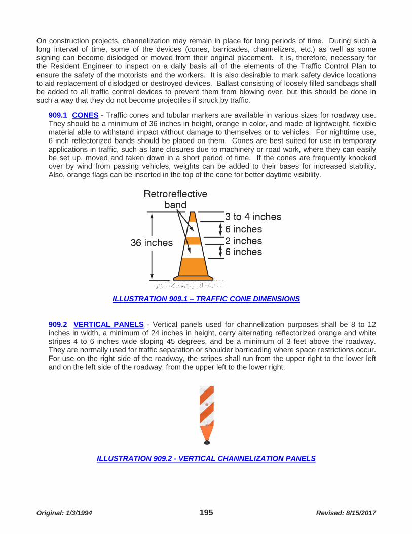
Original: 1/3/1994 195 Revised: 8/15/2017
On construction projects, channelization may remain in place for long periods of time. During such a long interval of time, some of the devices (cones, barricades, channelizers, etc.) as well as some signing can become dislodged or moved from their original placement. It is, therefore, necessary for the Resident Engineer to inspect on a daily basis all of the elements of the Traffic Control Plan to ensure the safety of the motorists and the workers. It is also desirable to mark safety device locations to aid replacement of dislodged or destroyed devices. Ballast consisting of loosely filled sandbags shall be added to all traffic control devices to prevent them from blowing over, but this should be done in such a way that they do not become projectiles if struck by traffic.
909.1 CONES - Traffic cones and tubular markers are available in various sizes for roadway use. They should be a minimum of 36 inches in height, orange in color, and made of lightweight, flexible material able to withstand impact without damage to themselves or to vehicles. For nighttime use, 6 inch reflectorized bands should be placed on them. Cones are best suited for use in temporary applications in traffic, such as lane closures due to machinery or road work, where they can easily be set up, moved and taken down in a short period of time. If the cones are frequently knocked over by wind from passing vehicles, weights can be added to their bases for increased stability. Also, orange flags can be inserted in the top of the cone for better daytime visibility.
ILLUSTRATION 909.1 – TRAFFIC CONE DIMENSIONS
909.2 VERTICAL PANELS - Vertical panels used for channelization purposes shall be 8 to 12 inches in width, a minimum of 24 inches in height, carry alternating reflectorized orange and white stripes 4 to 6 inches wide sloping 45 degrees, and be a minimum of 3 feet above the roadway. They are normally used for traffic separation or shoulder barricading where space restrictions occur. For use on the right side of the roadway, the stripes shall run from the upper right to the lower left and on the left side of the roadway, from the upper left to the lower right.
ILLUSTRATION 909.2 - VERTICAL CHANNELIZATION PANELS

Original: 1/3/1994 196 Revised: 8/15/2017
909.3 CHANNELIZERS - Drums used for traffic channelization shall be constructed of plastic, approximately 3 feet in height and 18 inches in diameter with alternating horizontal reflectorized orange and white stripes 4 inches to 6 inches wide. They are commonly used to channelize or delineate traffic flow but may also be used to mark specific hazards. Channelizers are portable but generally are placed where they will remain in place for a prolonged period of time. Small arrow signs or vertical panels can be mounted above the channelizers to supplement delineation, but added weight in the channelizers should not be used in traveled roadway applications.
ILLUSTRATION 909.3 - EXAMPLES OF CHANNELIZER TYPES 909.4 BARRICADES - Barricades can be either portable or fixed, having from one to three rails with appropriate striping and are used to control traffic by closing, restricting or delineating all or a portion of the roadway right-of-way. They shall be one of three types (Type I, II, or III) depending on their usage and application. The striping shall consist of alternating orange and white reflectorized stripes (4 to 6 inches wide) for the rails slope on a 45 degree angle to the left or right away from the work in the direction the traffic should follow. Normally, barricades are made of wood with A-Frame type bracing for larger ones (Type III) and with metal legs and wood rails for smaller sizes (Types I and II). When used in traffic, sandbags should be added on the lower part of the frame to prevent the barricades from being knocked over or moved out of position. The name of the contractor or supplier may be shown only on the back side of the barricade rails.
ILLUSTRATION 909.4A - EXAMPLES OF TYPE I & II BARRICADES

Original: 1/3/1994 197 Revised: 8/15/2017
Where traffic is to be maintained through the construction zone, Type I or Type II barricades should be used, singly or in groups, to channelize traffic or mark specific hazards. Maintenance operation, utility and emergency work usually requires these barricades. When a road section is closed to traffic, Type III barricades shall be erected at the point of closure and may extend completely across the roadway. Type II barricades should be used ahead of this point if local traffic, but not through traffic, is to be maintained. Appropriate detour and road closed signing should accompany these barricades. The Resident Engineer should make sure the contractor maintains the barricades in their proper positions when access is required to the job with equipment and they are moved frequently.
ILLUSTRATION 909.4B – EXAMPLE OF TYPE III BARRICADES
Barricades used with reflectorized taping can also mark paths for pedestrians through and around construction zones where sidewalks may be temporarily inaccessible. For nighttime conditions, flashing and steady burn lights can be added to barricades for higher visibility and aid in channelization. 909.5 PORTABLE BARRIERS - Barriers are designed to prevent vehicles from leaving the roadway and traveling into a construction zone or hazardous area while minimizing damage to an impacting vehicle and its occupants. They may be constructed of concrete or metal so that they physically deter access of vehicles to portions of the right-of-way. Barriers may also serve to channelize traffic and, in such usage, shall be supplemented by standard channelization or delineation markings. The effects of impacting the ends of the barrier should be minimized by flaring the ends away from the travel way and by using crash cushions.
ILLUSTRATION 909.5 (1) - EXAMPLES OF TYPE PORTABLE BARRIERS

Original: 1/3/1994 198 Revised: 8/15/2017
ILLUSTRATION 909.5 (2) - EXAMPLES OF TYPE PORTABLE BARRIERS 910 MARKINGS - When construction work necessitates the use of vehicle paths other than those normally used, a check drive through should be made to evaluate the possibility that existing pavement markings might lead drivers from the intended path. Inappropriate or misleading markings should be removed and new delineation placed before allowing traffic through. The intended vehicle path should be clearly defined for day, night and twilight periods under both wet and dry conditions. Where temporary roadways are constructed to by-pass a closed portion of the road or the vehicle path will be of a short duration, pressure sensitive traffic marking tape or raised pavement markers may be used in place of reflectorized paint to mark the lanes.
ILLUSTRATION 910 - EXAMPLES OF TEMPORARY PAVEMENT MARKINGS

Original: 1/3/1994 199 Revised: 8/15/2017
Maintenance activities normally do not require pavement markings, as they can be accomplished in one or more continuous shifts and are adequately protected by warning signs, flaggers and other channelizing devices. 911 DELINEATORS - Delineation in a construction and maintenance zones is intended to be a guide to indicate the alignment of the roadway and to outline the required vehicle path through these areas. Delineators are not to be used as warning devices.
ILLUSTRATION 911 - EXAMPLES OF DELINEATORS
Delineators are retroreflective units capable of clearly reflecting light under normal atmospheric conditions from a distance of 1,000 feet when illuminated by the upper beam of standard automobile lights. Reflective elements for delineators shall have a minimum dimension of 3 inches. Delineators, when used, shall be mounted on suitable supports so that the reflecting unit is about 4 feet above the near roadway edge. The standard color for delineators used along the right side of streets and highways shall be white. The color of delineators used along the left edge of divided streets and one-way roadways shall be yellow. Spacing along roadway curves should be such that several delineators are always visible to the driver. 912 LIGHTING DEVICES - Construction and maintenance activities often create conditions that are particularly hazardous at night. It is desirable and necessary under such conditions to supplement the reflectorized signs, barricades and channelizing devices with lighting devices. The three types commonly used are:
1) Floodlights for construction work or maintenance operations have a limited but important application. When high volume traffic conditions or the nature of the work being performed require a nighttime shift, floodlights become necessary. The job site should be well lit so that the workmen can see what they are doing and the passing motorists can see them. The lighting placement can best be determined by driving through the site and observing the floodlight area. Care should be taken not to create glare in the eyes of the passing drivers.
2) Flashing and steady burn warning lights are portable, lens directed, enclosed lights whose color
shall be yellow and are available in three variations. They have minimum mounting height of 36 inches above the roadway surface to the bottom of the lens. Type A warning lights are flashing low intensity lights, most commonly mounted on barricades, drums, vertical panels and advance warning signs. They operate on a dusk to dawn cycle. Type B warning lights are flashing high intensity lights normally mounted on advance warning signs or independent supports or on barricades for extremely hazardous work site conditions. They are designed to operate 24 hours per day. Type C warning lights are steady burn lights used to delineate the edge of the roadway on detour curves, lane changes, lane closures and other similar conditions. They can be mounted on barricades, drums or other channelizing devices and operate dusk to dawn.

Original: 1/3/1994 200 Revised: 8/15/2017
3) Advance warning arrow panels are special lighting units that are generally trailer mounted for easy transport and are operated from a self-contained power source on the trailer, either batteries or a power driven electric generator. They may be used for day or night activities, either construction or maintenance, and are particularly effective where the work is being conducted on a high density roadway. Arrow panels provide additional advance warning and are used in conjunction with necessary signs, barricades and other traffic control devices. They are available in 3 sizes ranging from 24 x 48 inches to 48 x 96 inches with the panel face finished non-reflective black and a minimum of 12 to 15 lamps flashing at a rate of not less than 25 times per minute. Minimum legibility on a clear day or night should be no less than ½ to 1 mile, depending on the size of the panel.
913 FLAGGING AND HAND SIGNAL PROCEDURES - The most common hand signaling devices used in controlling traffic through work areas are the red flag and "Stop-Slow" paddle. Flags should be a minimum of 24 x 24 inches and made of a good grade synthetic material, red of bright orange in color. Sign paddles should be at least 18 inches wide with letters 6 inches tall, fabricated from sheet metal with a rigid handle. The background of the "Stop" face shall be red with white borders and letters. The background of the "Slow" face shall be orange with black borders and letters. For use at night, the sign shall be reflectorized.
ILLUSTRATION 909.4A - FLAGGING & HAND SIGNAL PROCEDURES The sign paddle bearing the clear messages "Stop" or "Slow" provides motorists with more positive guidance than flags and should be the primary hand signaling device. Flag use should be limited to emergency situations and at spot locations which can be best controlled by a single flagger.

Original: 1/3/1994 201 Revised: 8/15/2017
SECTION 1000 MATERIALS TESTING 1001 GENERAL - The purpose of materials testing is to provide assurance of compliance on stipulated quality of materials, as specified in the Specifications and the Special Provisions, used in the various construction phases. For the necessary quality control on a County Project, this materials testing may be divided into three categories: Field Testing, County Laboratory Testing and testing by other agencies. All materials provided for the construction of the project are subject to inspection and may be accepted or rejected either totally or in part. The contractor will comply completely in the testing of materials and will solicit the aid of material suppliers and producers to facilitate on-site inspections. Testing will be performed in accordance with accepted procedures and at a frequency which will ensure uniformly acceptable results. In general, testing procedures will follow either American Society for Testing and Materials (ASTM) or American Association of State Highway and Transportation Officials (AASHTO) guidelines. These updated procedures are available for reference at the Materials Testing Laboratory. The Materials Engineer is the contact person for the acquisition of testing materials and apparatus, for test results performed by the laboratory personnel and for scheduled inspection of materials produced on a daily basis. Call (314) 615-1187 (Materials Order Desk) between 2:30 pm and 3:15 pm of the work day before inspection is needed (2 days for night work, weekends or holidays). Major operations which will require extensive inspection (i.e. bridge deck pour, main line paving, etc.) should be coordinated at least one week in advance of the work. The assignment of Materials Testing Laboratory inspection personnel will be under the direct supervision of the Materials Engineer; however, it will be the responsibility of the Resident Engineer to communicate with the plant inspector while attempting to establish uniformly consistent material from a given source. Should a major problem arise in the quality or uniformity of the material being used, the Materials Engineer should be contacted immediately. 1002 FIELD TESTING - On site testing is performed to provide the Resident Engineer with information which will direct his judgment as to the quality of operations being performed by the contractor. The testing should be performed in a manner which will provide accurate and timely results. Ideally, each person on the project should be qualified to complete the materials testing required. The Resident Engineer may designate one inspector to be in charge of all materials testing and the recording of all results in the Materials Testing Book. The Inspector should report all results to the Resident Engineer and provide him with copies of materials testing reports for the Project Files and to be forwarded to the Materials Engineer. The Resident Engineer should be thoroughly familiar with all testing procedures and requirements. He should be able to recognize the sources of error which may affect test results. The Resident Engineer should oversee the testing performed by inspection personnel and should periodically check testing procedures for conformity to specified procedure. The minimum field schedule for testing is shown in Table 1017B. 1003 SOILS TESTING - Obtaining Soil Samples by Resident Engineer. At the commencement of the project, the Resident Engineer should, with the assistance of the contractor, obtain soil samples which will be representative of the soil on the project to be incorporated into the embankments. These samples should not contain organic material and should be taken at locations on the project within the right-of-way and at elevations which will be reached during the course of roadway construction. A separate sample will be required from each borrow site that is used

Original: 1/3/1994 202 Revised: 8/15/2017
on the project. A canvas sample bag may be obtained at the Materials Testing Laboratory, and an average sample will weigh about 50 pounds. The sample should be properly labeled (Project No., Location, Date and Quantity) and delivered to the Materials Testing Laboratory to be used to establish a Standard Proctor for density control, along with the liquid limit and the plastic index of the individual soil. (See County Laboratory Testing.) Approximately 5 to 7 working days will be required to obtain these desired results. Aggregate samples for testing will be acquired by Materials personnel.
1003.1 EQUIPMENT REQUIRED - The preferred modern method to determine soil compaction is with the Troxler or Humboldt Nuclear Density Gauge Device. Users are required to take an annual Radiation Safety training course prior to being authorized users of the device. Training sessions are typically in February or March of each year and provided by the Materials Lab.
ILLUSTRATION 1003.1A - NUCLEAR DENSITY GUAGE
An alternate way of determining field density is by way of the Sand Cone Test. See the "You Tube" video at the link below (or follow instructions detailed at the link):
https://www.youtube.com/watch?v=ojH0W3xq3P0
ILLUSTRATION 1003.1B - SAND CONE DENSITY TEST

Original: 1/3/1994 203 Revised: 8/15/2017
The following equipment is required for obtaining samples for density determination by the sand cone method:
1) Sand cone density apparatus (obtain at Materials Testing Laboratory).
2) 10 kgm balance and 500 gm balance with weights (obtain at Materials Testing Laboratory). Both balances should be zeroed before any testing is performed. Balances should remain undisturbed and checked before each test.
3) Heating unit (obtain at Materials Testing Laboratory).
4) Sample drying pan (obtain at Materials Testing Laboratory).
5) Sugar scoop, large spoon, screw driver with long shank, pliers and gallon sample can with
lid (obtain at materials Testing Laboratory).
6) Silica Sand (obtain at Materials Testing Laboratory). 1003.2 FIELD DENSITY TEST BY SAND CONE METHOD - The field density test is used to relate the density of a given sample to that of a standard sample having a fixed moisture content which has been compacted by a specified force. In this test, the moisture content and compactive force are variables which are graphically illustrated in the soil proctor curve. (See County Laboratory Testing.) This density test applies equally to soils and aggregate base courses. The Sand Cone Method (AASHTO T-191-61) is used to determine density as specified in the Specifications. Results obtained from this test will depend upon the following factors:
1) Particle size and physical properties of the material.
2) Moisture content of the soil
3) Type and amount of compactive effort expended. The liquid limit, plastic limit and plasticity index are measures of the quality of the soil to be used. The Standard Proctor curve provides a maximum soil density with minimum compactive effort at moisture content considered "optimum" for the soil to be used. These factors will provide the basis for determining the quality of any embankment construction. The following testing procedures should be observed in conducting a moisture-density determination:
1) The silica sand used to fill the excavated sample void must be calibrated to obtain an accurate mass. This calibration is performed at the Materials Testing Laboratory.
2) The cone of the sand cone apparatus must also be calibrated to determine the weight when
filled with the silica sand. This calibration is performed as follows:
a) Fill the sand cone apparatus with silica sand.
b) Using the 10 kgm balance, weigh the sand cone apparatus and record the weight.

Original: 1/3/1994 204 Revised: 8/15/2017
c) Place sand cone in sample pan, open valve and allow cone to fill. (Caution: Do not vibrate table or assembly, as a false reading will result.)
d) Close valve and remove sand cone apparatus.
e) Weight sand cone apparatus and remaining sand. The difference is the weight of sand
in the cone. (Note: By knowing that the volume of the cone is nearly .037 cubic feet, a double check of the calibration weight of the silica sand is possible.
Calibrations are vital for accurate results and should be performed when sources of silica sand are changed or test results become erratic. The following procedure should be utilized in performing the Sand Cone Method (AASHTO T-191-61) test:
1) Preparatory to the test, County Form 4505, "Field Density", should be obtained at the Materials Testing Center Laboratory.
The known quantities should be entered on the form. Line 7 is calibrated weight of sand in cone (determined in Step 2), Line 9 is calibrated weight of sand (determined in Step 1) and Line 20 is maximum dry density as provided in Standard Proctor curve information.
2) The sand cone apparatus should be filled with calibrated sand. Approximately 14 to 16
pounds of sand should be required per test. Weigh the total sand and apparatus and enter on Line 4 of the form.
3) Weigh the empty gallon sample can with lid and enter on Line 2 of form.
4) The location of the test volume sample should be carefully selected. The intent of this test is to provide a representative view of the compactive effort being provided by the contractor. Unstable areas and obviously well-compacted areas should be by-passed in favor of an area which represents the general condition of the embankment. Once determine, the station location and distance left or right of centerline should be obtained and recorded. The approximate elevation of the sample being taken should also be obtained. Loose dirt and rock should be removed and a test site of 2 x 2 feet minimum leveled for testing.
5) Seat inverted sand cone apparatus on leveled surface and mark outline of cone. Remove sand cone apparatus.
6) Beginning at the center of the outlined area, loosen and remove material and place in sample can. Care should be taken to keep the material adjacent to the outline from becoming dislodged. A volume of 0.05 cubic feet should be removed from the area. This will translate to a 6 inch diameter hole 4 inches in depth. The walls of the hole should be as vertical and smooth as possible. Any non-typical material (i.e. rock, roots, etc.) should be removed during sample removal but replaced when sample taking is completed. The hole should be cleaned of as must loose material as possible. All sample material should be placed in the sample can with care taken to maintain the total sample. The can should be kept covered as much as possible to prevent moisture loss. Seal sample can when completed.

Original: 1/3/1994 205 Revised: 8/15/2017
a) Invert sand cone apparatus and seat over sample hole being careful not to dislodge any material into the sample volume hole. Open the valve and allow sand to fill the sample volume hole and sand cone. (Note: Vibration from nearby equipment will affect test results, perform tests away from earth moving or compaction equipment.)
b) Close valve in sand cone apparatus (be sure valve is completely closed). Remove test
apparatus to Project Office and weigh, recording results on Line 5 of the test form. Also weigh sample in sample can with lid and record result on Line 1 of test form.
c) By deducting Line 2 (weight of can with lid) from Line 1 (weight of sample and can),
the weight of the sample may be determined (line 3). By deducting Line 5 (final apparatus weight) from Line 4 (initial apparatus weight), the weight of sand required to fill the sand cone and sample volume hole may be obtained (Line 8). By dividing the weight of sand required to fill the sample volume hole (Line 8) by the calibrated unit weight of sand (Line 9), the volume of the sample hole (Line 10) may be obtained. By dividing the sample volume weight (Line 3 or 17) by the volume of the sample volume hole, a wet density may be obtained (Line 18).
1003.3 MOISTURE CONTENT DETERMINATION - In order to complete the density test procedure, it is necessary to perform another field testing procedure, the Moisture Content Determination. This test is used to indicate the percentage of moisture in a given sample of material. This test has application not only to the density determination but is also used in determining aggregate moisture correction factors for water-cement ratios and for placing of certain bituminous products. The following procedure should be followed to make a moisture content determination:
1) Using the 500 gram balance, determine the empty weight of the sample pan and record same on Line 13 of Form 4505.
2) Unseal sample can and place 300 to 400 grams of material in sample pan and establish wet
weight (record on Line 11). (Note: Be sure sample is not segregated – a representative sample is required. The sample should be obtained from various areas within the can in order to ensure the sample is representative).
3) Place sample on heating unit and evaporate water from sample (using medium heat setting
on unit).
4) When all moisture is gone from sample (check dryness with a watch glass), weigh sample and record on Line 12. (Note: Observe cooled sample on balance, sample should become heavier as moisture from air is re-absorbed, this will provide a check on dryness of sample for weighing).
5) Obtain moisture weight by subtracting dry weight of sample and pan (Line 12) from wet
weight of sample and pan (Line 11). Obtain dry weight of sample by deducting weight of pan (Line 13) from dry weight of sample and pan (Line 12). Obtain percentage of moisture by dividing moisture weight (Line 14) by dry weight of sample (Line 15) multiplied by 100 to express a percentage.

Original: 1/3/1994 206 Revised: 8/15/2017
As moisture content is a variable quantity in the density testing procedure, a comparison to "optimum moisture" for the specified material should be made. If the moisture determination for a given sample varies by more than ± percent, compactive effort will have to be increased to obtain the required degree of density. The contractor should be notified when this condition occurs. When the moisture content of a soil sample is measured at 2 or more percentage points below optimum moisture, the contractor will find is beneficial to add water as he placed embankment. If the moisture content of the soil sample exceeds the optimum moisture level by more than 2 percentage points, the contractor will probably be required to dry out the material as he works it to obtain adequate in place density of the soil. When the percentage of moisture is known for a given sample, it is possible to compute the "degree of compaction" as compared to a standard. This is computed as follows:
1) The wet density (Line 17) is divided by 1.00 plus the moisture in the sample expressed as a decimal (Line 16). This yields the sample dry density.
2) The sample dry density is divided by the standard dry density as established in the proctor.
This result multiplied by 100 expresses the degree of compaction in a percentage. 1003.4 SIGNIFICANCE OF TESTS - The degree of compaction is a tool which monitors the shear resistance of the embankment due to density. As previously stated, compaction depends on the character of the soil, moisture, and compactive effort. The character of the soil cannot be changed, so moisture and compactive effort must be regulated to obtain the required results. The specifications set forth the compaction and moisture limitations for roadway embankments composed of soil when moisture and density control is established for the project. These specifications also apply to projects where no specific moisture or density control is established. Several factors may affect the accuracy of the compaction test. These are as follows:
1) Material being tested is not consistent in physical qualities with the material used to establish the proctor curve. When this condition occurs, test results will be inordinately in excess of 100 percent compaction, or increased compactive effort will produce little change in the degree of compaction. A change in material will usually be accompanied by a color, texture or visible granular size change in the material. A new proctor will have to be run to establish new dry density and optimum moisture conditions.
2) Volume of test hole too small or false volume. It is imperative that the volume of the sample
hole to be at least .05 cubic foot. The intent is to test the compaction in the entire lift of material placed, not just in the top layer which will receive the most compactive effort. Compaction results in excess of 120 percent are possible when an inadequate volume is tested.
False volumes in the sample hole are caused by testing being performed in unstable or saturated subgrade areas. In these areas, the sides of the sample hole will sag inward reducing the volume of the sample hole as compared to the weight of the material removed. This will increase the compaction results. Also, it is possible to have tapered sides in the sample hole or projections which impede the flow of the silica sand, thereby reducing the volume.

Original: 1/3/1994 207 Revised: 8/15/2017
3) Rock particles in the soil. This is another deviation from the proctor as established for a particular soil type. As the proctor is determined by using material which will pass a ¾ inch sieve, any large stone should be replaced in the sample hole. Small rock mixed in the sample will increase the weight of the material removed from the sample hole, increasing the density. In accordance with the specifications, material having more than 20 percent retained on a ¾ inch sieve is considered too rocky to be tested accurately.
Test results for the standard density test should range from a minimum of 85 percent for uncompacted cut in natural ground to a maximum of 105 percent for aggregate or soil which has had compactive effort applied in excess of that which will give the desired results. 1003.5 FREQUENCY OF TESTING - The "Schedule for Materials Sampling and Testing" specifies a frequency of testing of one test per layer per 0.25 mile or 1,250 cubic yards for embankments and one test per cut per 500 feet. On many of the projects the Resident Engineer will need several times this number of tests for assurance of compliance. As this testing frequency represents a minimum number, the Resident Engineer should satisfy himself as to testing required, being sure to thoroughly check for compliance in compaction. Emphasis should be placed on very complete testing being performed in the area around major structures and approach slabs. The frequency of testing in aggregate bases should follow the above specified pattern with consideration of quality control predominating minimum requirements. The minimum requirements for density and thickness in aggregate bases will be one test per layer per 0.25 mile and one test per 500 tons for moisture control.
1004 CONCRETE TESTING - The field testing of concrete is intended to provide the Resident Engineer with an on the spot measure of the quality of the various classes of concrete being produced for inclusion in the construction project. The field testing of concrete is in three phases: Slump Test, Air Content Test and Compression Cylinder Test. The materials Engineer is responsible for providing the design mixes for the various classes of concrete and the inspection personnel to inspect the proportioning and mixture of the concrete at its source. The specifications provide the basic requirements for the production of concrete for use on all projects.
1004.1 EQUIPMENT REQUIRED - The following equipment will be required to perform the concrete testing in accordance with established procedures:
1) Slump cone apparatus with testing surface (obtain at Materials Testing Laboratory).
2) Flat strike off, tamping rod, rubber mallet, sugar scoop and 2 gallon or larger capacity bucket (obtain at Materials Testing Laboratory).
3) Air Content Meter (obtain at Materials Testing Laboratory).
4) Compression Strength Cylinder Molds (obtain at Materials Testing Laboratory).
5) Concrete Thermometer (obtain at Materials Testing Laboratory).

Original: 1/3/1994 208 Revised: 8/15/2017
1004.2 SLUMP TEST - The slump test is a measure of the consistency of the concrete. The slump of a concrete sample is expressed in inches and must not exceed the allowable limits expressed in the slump and mixing water requirements of the specifications. Under no circumstance can the mixing water requirement, as expressed in gallons/sack, enumerated in the above stated specification be exceeded, regardless of slump. The Inspector should never advise the contractor on the amount of water to use in the concrete mixture. It is the contractor's responsibility to determine the amount of mixing water required to produce a useable mix. If the contractor asks if he can add water to the mix, he should be advised of the maximum permissible amount of mixing water allowed and the limitations on the slump of the mix. Water may not be added to the mixture more than twice. Each time water is added, the mixing drum should be revolved 30 times at the proper mixing revolution rate. The following link will take you to a video of a live slump test being performed and narrated
https://www.youtube.com/watch?v=EqKmtcF46lg The following procedure should be followed to perform a slump test:
1) The concrete must be sampled in accordance with AASHTO T-141-74. This procedure requires sampling at three intervals during the discharge of concrete, except for central or truck mixes. In this case, one sample may be taken after approximately 1 yard of concrete has been discharged. This sample should be homogeneous and representative of the entire mass. A large enough sample should be taken to provide for all three tests. The sample should be placed directly on a clean, level, rigid, moistened surface with the necessary testing performed as soon as possible. No further discharging of concrete should be allowed until testing is completed. This test should be performed after all additional mixing water has been added.
2) The slump test must conform to AASHTO T-119-74. The slump cone should be wetted and
placed on a rigid, level, moistened surface. The ears of the slump cone should be stepped on and a steady pressure maintained during the test.
3) The concrete for the test should be removed from the sample and placed in the slump cone.
The concrete is placed in 3 even layers (by volume, not by height) with 25 roddings from the tamping rod being distributed over each layer before the next layer is placed. The rodding should be done evenly and should penetrate the entire layer being consolidated and into the layer beneath. The cone should be overfilled in the last layer and, after rodding, struck off flush with the top of the cone.
4) Grasp the handles on the slump cone and step off the ears of the cone, being sure to
remove any loose concrete from around the base of the cone. With a steady vertical motion, remove the slump cone (within 5 seconds ± 2 seconds) (do not twist or move the slump cone laterally) and place on the surface adjacent to the slump sample.
5) Place the flat strike off atop the slump cone and measure the amount the sample has
slumped from the top strike off level of the slump cone to the top of the sample. The distance from the strike off level of the slump cone to the displaced center of the sample is the slump of the concrete and should be measured to the nearest ¼ inch.
6) Record the result on County Form C-50 (revised 3/8/1991) "Data on Concrete Test
Specimens".
7) Dispose of the slump sample outside the form line and clean the equipment.

Original: 1/3/1994 209 Revised: 8/15/2017
The slump test must be used to maintain a consistent concrete for the item being poured. The contractor has the privilege of raising the slump toward the allowable maximum based on the class of concrete. Any adjustment in mixing water should be noted on Form C-50, and the material must be resampled to maintain the concrete within the specified parameters. The slump test is an easy, quick and uncomplicated method for determining the consistency of the concrete. Test results are adversely affected by improper tamping and by shifting of the slump cone during the consolidation of the concrete sample in the cone. These two factors most often produce a shearing or non-uniform slumping of the sample. An unleveled base upon which the slump cone test is set will also produce a non-uniform slumping of the sample. 1004.3 AIR CONTENT TEST - The air content test is used to express the volumetric percentage of air in the concrete sample. The concrete, as produced, will by nature contain 1.5 to 3.0 percent air by volume. For most classes of concrete and for most construction applications, an admixture is added to the concrete during the mixing procedure to chemically induce additional air in the concrete. A figure of 6½ percent air content has been established as optimum for ease of finishing and increased serviceability of the concrete. A tolerance of ±1½ percent has been deemed allowable for variation from optimum. The following link will take you to a video of a live air test being performed and narrated
https://www.youtube.com/watch?v=CfVaR79OgX8 The following procedure should be followed to perform an air content test:
1) The sampling of the concrete should be done in accordance with AASHTO T-141-74 as mentioned in the slump test.
2) The Air Content Test must conform to AASHTO T-152-74. The air meter and all test
equipment should be wetted and a volume of water placed in the bucket for use in the procedure. The air meter should be disassembled and the base placed on a rigid, level surface.
3) The concrete should be placed in the base from the sample taken previously in 3 equal lifts
and rodded 25 times per lift with the tamping rod as in the slump test. Each lift should be consolidated by tapping the base with the rubber mallet (10 to 15 times). The last lift of sample concrete should be overfilled and struck off with the flat edged strike off. Care should be taken to strike off the final lift flush with the top of the base (plugging of the petcock holes may occur if the base if overfilled - voiding the test). The strike off concrete should be finished as smoothly as possible with no holes left in the finished surface.
4) The rim of the base should be hand-washed and cleaned of any sand or aggregate which
would interfere with a tight seal to the top of the apparatus. The top should be wetted and wiped clean before placing on the base. The top of the apparatus is secured to the base by 4 clamps attached to the top. It is important that these clamps be adjusted to the length which will provide for a positive seal between the top and base to prevent the escape of the compressed air used in the procedure. These clamps may be adjusted to length by screwing the adjusting rod in or out as required to obtain a positive seal.

Original: 1/3/1994 210 Revised: 8/15/2017
5) The petcocks on the top of the apparatus should be opened and the syringe, which is provided with the air meter, should be filled with water. The syringe should be used to fill the petcocks by gently flowing the water into the petcock on one side until full and then on the other side until a reverse flow of water is noted. (It is necessary to fill the slight void and both petcocks in the top of the apparatus completely with water for an accurate test).
6) The air percentage gauge should be pumped to the initial setting located in the lower right
portion of the meter. To do this, the air release valve must be closed. This valve is located atop the air meter on the air compression cylinder next to the air pump. The initial pressure setting should have been predetermined by a calibration performed at the Materials Testing Laboratory. The gauge should be tapped after pumping is completed to ensure sticking of the needle has not occurred.
7) The petcocks should be refilled and closed, the initial setting of the gauge checked and then
the pressure should be released by firmly pushing down on the pressure release handle next to the air release valve. The needle should move from the setting to a point which will indicate the percentage of air in the concrete. The gauge should again be lightly tapped and the air content reading recorded on the same form as the slump reading.
8) Open the petcock opposite your position to release the air pressure in the base and
disassemble apparatus. Open air release valve until needle in gauge reaches hand free position. Dump concrete sample outside form line and clean equipment completely. Do not use this sample in the concrete pour.
The reading obtained in this test is an indication of the volume of air in the concrete sample. From this result, a correction for the porosity of the aggregate must be made. This correction factor is normally computed at 0.25 percent and should be subtracted from the reading to obtain the corrected figure. The accuracy of the air content test is primarily dependent on the mechanical integrity of the testing equipment. In order for an accurate test to be completed, a positive seal must be present at the interface between the top and base. Failure to obtain a positive seal presents the greatest chance of error due to pressure loss. When the results of the air content test indicate a percentage of air below the acceptable level, it is possible to increase the air content by the addition of water and the rotation of the concrete mixing drum, provided the slump will allow the addition of the water and the maximum number of mixing revolutions is not exceeded. When the test results show the air content to be in excess of the allowable, the concrete should be rejected. Several factors affect the air content of the concrete after batching. These are:
1) Improper transportation and mixing equipment.
2) Length of haul and rough road conditions.
3) Various admixtures and hot mixing water.
4) Concrete aggregate gradation and cement content.
Each can have a detrimental effect on the air content of the concrete and should be considered as potential problem areas should a problem arise.

Original: 1/3/1994 211 Revised: 8/15/2017
1004.4 COMPRESSION CYLINDER TEST - The compression cylinder test provides the Resident Engineer with a means of measuring the strength of the concrete placed on the project. The compression strength developed in the concrete is one of the key considerations in the development of the design mix and provides an indication of the quality and life span that can be expected from the various concrete items. Compression strength is also used as a guide for the backfilling, removal of false work and opening of structures and roadways to traffic. The following procedure should be used when preparing compression cylinders in the field:
1) The concrete should be taken for sampling in accordance with AASHTO T-141-74 as with the slump and air content test.
2) The compression cylinders must be cast and cured in accordance with ASTM Method C31.
The compression cylinders should be cast from concrete which has also been sampled for slump and air content. A set of 4 or 6 cylinders will be cast at any time using the molds provided by the Materials Engineer which meet ASTM C470 conditions.
3) The cylinders should be placed on a rigid level surface, preferably in the shade, and in a
position where they will remain unmoved for 24 hours. It is important that the cylinders, once cast, be maintained at a temperature between 60°F and 80°F.
4) The concrete cast in the compression cylinders should be placed in 3 even lifts with 25
strokes from the tamping rod distributed evenly over each layer as in the air content test. The sides of the cylinder mold should be tapped with the rubber mallet. The final layer in the cylinder mold should be slightly overfilled and struck off even with the top of the mold and finished as smoothly as possible.
5) The cylinder mold should be covered with a plastic bag or cap provided by the Materials
Engineer. This covering should be made as soon as possible. (Note: Should it be necessary to relocate the molded cylinders, it should be done while the concrete is still in a plastic state; this should be avoided if possible.)
6) The cylinder should not be moved for 24 hours, but shall be transported to the laboratory as
soon as possible thereafter. If it is inconvenient to transport the aged cylinders to the Materials Testing Laboratory, they should be stored in wet sand, completely covered, until they can be transported. When transported, the cylinders should be laid flat and protected from rolling or bumping. The Resident Engineer should note any deviation in the storage or transport of the cylinders on Form C-50.
7) Form C-50 must be presented with the cylinders at the Materials Testing Laboratory. In
addition to the slump and air content previously recorded on the form, it will also be necessary to record the gallons of water added, weather conditions, ambient temperature, concrete temperature and the general information required at the top of the form. This same information should be recorded in the Materials Testing Book and the test report coded for ease of reference when 7 day and 28 day cylinder compression strength is checked.
The compression cylinders are an indicator of the strength of the in place concrete. The permanency of the structure or roadway will depend in large part on the compression strength of the concrete. Care should be taken in the preparation of the cylinder. Care should also be taken not to move the cylinders in the first 24 hour period. Disturbed cylinders should be discarded and so noted on Form C-50. Care should be taken in transportation of the cylinders to prevent fracturing by dropping or hitting. These factors may be the cause of low and erratic compression strength results.

Original: 1/3/1994 212 Revised: 8/15/2017
1004.5 SIGNIFICANCE OF TESTS - The purpose of these concrete tests is to provide for a uniform, consistent product. The information obtained from these on-site tests will allow for adjustments at the point of production, which should provide a uniformly homogeneous product with uniform characteristics within the allowable parameters. Materials which do not meet the parameters set forth in the specifications for cement, slump, mixing water and air content should be rejected. Concrete that exceeds the time limit from batching to final discharge or a temperature of greater than 90°F when placed in a bridge deck should be rejected. The Materials Engineer should be notified of these rejections, as should your immediate supervisor. The results of all materials testing should be recorded in the Materials Testing Book, and the plant materials inspector should be kept informed as to results and the need for alterations in the concrete mix. The ticket should be signed and marked "Rejected" – "No Pay" with the reason for rejecting the material noted. A copy of the ticket should be retained for your records. 1004.6 FREQUENCY OF TESTING - The three phases of concrete testing are for only one purpose – to provide a consistent workable concrete. With this in mind, the testing should be conducted at whatever frequency is necessary to establish and maintain this objective. The "Schedule for Materials Sampling and Testing" provides for minimum testing requirements only. Portland cement concretes are to be rested at a minimum frequency of one test per 250 cubic yards or one per day (slump, air content and compression cylinders). Structural concretes are to be tested at a frequency of one test per 100 cubic yards or one per day. In the course of obtaining a consistent, workable concrete product, a full complement of tests may not be required each time. Slump and air content tests should be used as required to determine results and interpret the effect of adjustments to the design mix. When a consistent, workable product is produced, the complete compliment of tests (slump, air content and compression cylinders) should be taken for a representative sample.
1005 COUNTY LABORATORY SOILS TESTING - The Materials Testing Laboratory provides testing of construction materials to be utilized in the various segments of the project. A number of these test procedures are conducted on a periodic bases as required in the "Minimum Field Schedule for Materials Sampling and Testing" or by the specifications. The specifications require testing of materials and establish parameters of acceptability for their use. The purpose of this testing is to provide the Resident Engineer with the assurance that the quality of the materials used on the project which he cannot test on site is within the required parameters and is acceptable. As many of these tests must be run for several projects and require adherence to an established procedure, ample time must be allowed for results to be obtained. Testing of construction materials will be done utilizing ASTM or AASHTO procedures. The Materials Engineer should be contacted when a specific or non-standard test is being performed. In general, the Materials Engineer will perform all needed laboratory testing without specific notice being given to the Resident Engineer. The results of these tests will be forwarded to the Resident Engineer or may be acquired at the Materials Testing Laboratory. Where samples of materials for testing are to be taken in the field, the Resident Engineer should arrange for sample containers, sampling and delivery to the Materials Testing Laboratory for completion of the testing. The following is a list of tests performed at the Materials Testing Laboratory.
1005.1 ATTERBERG LIMITS - The Atterberg Limits are the moisture content of a soil at points where the soil's physical properties transform from one state to another. They are individually defined as follows:

Original: 1/3/1994 213 Revised: 8/15/2017
1) Shrinkage Limit - The shrinkage limit test is performed in accordance with AASHTO T-T-92-70 and delineates the semi-solid from the solid state. Values of this test will range from 6 to 14 for clay soils and from 15 to 30 for silty soils. This test is not normally performed unless specifically requested.
2) Plastic Limit - The plastic limit test is performed in accordance with AASHTO T-90-70 and
represents the moisture content at which a soil changes from the semi-solid to the plastic state. The plastic limits of silts and clays will range from 5 to 30 and will not vary widely. Normally, the more silty soils will have the lowest plastic limits.
3) Liquid Limit - The liquid limit test is performed in accordance with AASHTO T-89-76 and
represents the moisture content at which a soil changes from the plastic to the liquid state. Generally, soils with high liquid limit values are clays with poor engineering properties. The normal limits for clay soils will range from 40 to 60, with heavy clays ranging up to 85. For silty soils, the normal values will range from 25 to 50, with sandy soil producing no result or a non-plastic condition.
The plasticity index is the difference between the liquid limit and the plastic limit and represents the range of moisture content over which a material is in the plastic state. The higher the plastic index, the more likely the material is to be a clay; the lower the plastic index, a silt. The normal range of clay soils will yield a plastic index of 20 to 40, while the normal range of silt soils will range from 10 to 20. The liquid limit and plastic index of a soil will provide an evaluation of its quality for construction applications. For quality considerations, the greatest soil stability will appear in soils with a liquid limit of 25 or less and a plastic index with a maximum of no more than 6 (basically, a granular material) which is normally not available for embankment construction in this area. The St. Louis area has two basic soil types, a clay, which will have a liquid limit ranging from 35 to 85 and a plastic index ranging from 15 to 55, and alluvial or loessial silt having a liquid limit ranging from 25 to 45 and a plastic index in the range of 5 to 30. These two soil types will be stable within a narrow range of moisture. It will be necessary to closely monitor soil moisture and control that moisture content in order to maintain stability in the embankment. The specifications provide limitations for moisture content and methods of compaction necessary to provide the desired embankment stability. 1005.2 MOISTURE-DENSITY RELATION (PROCTOR TEST) - The moisture-density test or proctor test must be conducted in accordance with AASHTO T-99 procedures for the standard moisture-density test or AASHTO T180 procedures for the modified moisture-density test. The specifications are based on relationships derived from the Standard Proctor Test. The purpose of the moisture-density test is to provide the Resident Engineer with a means of compacting a material so as to obtain the highest shear resistance by obtaining the maximum density. The test is designed to obtain the best results from the soil available. The point at which the maximum density is obtained is partially governed by a moisture content in the soil which best acts to lubricate and consolidate individual soil particles; this moisture content is termed "optimum" and provides a narrow range of values for maximum density and soil stability. This information is illustrated on the graph which accompanies the soil test information. The compactive effort provided by the compaction equipment is the remaining variable factor in obtaining the maximum density of an embankment. The standard moisture-density test is based on the assumed average compactive effort available with the more common types of compaction equipment. When greater compactive effort is applied, the compaction may range beyond the standard maximum density figure. This possibility is the basis of the modified moisture-density test which assumes a higher compactive effort being applied to the embankment.

Original: 1/3/1994 214 Revised: 8/15/2017
The following range of values may be anticipated for the standard moisture-density test:
TABLE 1005.2 - STANDARD RANGES FOR MOISTURE-DENSITY TEST (AASHTO T-99)
Clays: ........................ Maximum Density ................. 90 to 105 Pounds per Cubic Foot Optimum Moisture ................ 20 to 30 Percent Silty Clays: ................ Maximum Density ................. 100 to 115 Pounds per Cubic Foot Optimum Moisture ................ 15 to 25 Percent Sandy Clays: ............. Maximum Density ................. 100 to 135 Pounds per Cubic Foot Optimum Moisture ................ 8 to 15 Percent Silts: .......................... Maximum Density ................. 98 to 110 Pounds per Cubic Foot Optimum Moisture ................ 11 to 17 Percent
The expected results for the modified moisture-density test will range from 5 to 10 pounds per cubic foot higher for maximum standard density and 3 to 10 percent lower in optimum moisture content. Generally speaking, soil compacted to 95 percent of a Standard Proctor will approximate the same in place density of soil compacted to 90 percent of a modified proctor. 1005.3 FREQUENCY OF TESTING - Generally, the liquid limit and plastic limit tests are conducted as a standard battery of procedures for each sample of soil presented for determination by the Resident Engineer. One such set of tests should be executed for each classification of soil type per roadway cut or embankments, including any borrow excavation. This requirement provides the Resident Engineer with a degree of responsibility in the establishment of differing soil strata for testing. The shrinkage test is conducted only as requested by the Resident Engineer. The moisture-density test is conducted as a standard part of the battery of testing performed on soil samples presented for classification and at the same frequency as other Atterberg Limits Tests. When, throughout the course of the embankment placing operation, it becomes apparent that the physical properties of the borrow material have changed, the Materials Testing Laboratory should be notified.
1006 COUNTY LABORATORY AGGREGATE TESTING 1006.1 ATTERBERG LIMITS - The liquid limits test and plastic index test are conducted on that portion of the aggregate bases which will pass the No. 40 sieve. From these results, the plastic index may be computed with the following limits established in the specifications:
TABLE 1006.1 - STANDARD ATTERBERG LIMITS VALUES
Type 1 Aggregate for Base................................................................ Plastic Index - 0 to 6
Type 2 Aggregate for Base, Chat or Crushed Stone.......................... Plastic Index - 0 to 6
Sand and Gravel ............................................................................... Plastic Index - 0 to 6
Type 3 Aggregate for Base................................................................ Plastic Index - 0 to 8
Sandstone, Sand or Sand Gravel ...................................................... Plastic Index - 2 to 8

Original: 1/3/1994 215 Revised: 8/15/2017
1006.2 MOISTURE-DENSITY RELATION - The moisture-density test is conducted for aggregate base courses as for soils so that compaction may be obtained as the specifications require. The following range of values may be anticipated for aggregate base courses produced in the St. Louis area:
TABLE 1006.2 - ANTICIPATED AGGREGATE BASE MOISTURE-DENSITY RESULTS
Type 1 Aggregate: Maximum Density ..................................... 125 Pounds to 140 Pounds per Cubic Foot Optimum Moisture .................................................................. 7 Percent to 14 Percent
Type 3 Aggregate:
Maximum Density .................................................. 130 to 138 Pounds per Cubic Foot Optimum Moisture .................................................................. 9 Percent to 14 Percent
Type 2 and 4 Aggregate for base are very infrequently used as are Portland cement treated bases. In the event these bases were to be used, the proper testing would be performed to establish the Atterberg Limits and moisture-density relations. 1006.3 GRADATION TESTS - The determination of gradation by sieve analysis is performed in accordance with AASHTO T-27. The sieve analysis requirements for aggregate bases (Types 1 to 4) are specified in the specifications. 1006.4 FREQUENCY OF TESTING - The Atterberg Limits Tests are made on a basis of one per material supplier. This determination for the plasticity index is made for that part of the aggregate sample passing the No. 40 sieve. The moisture-density relationship is also made at a frequency of one per source. The gradation test is made at a frequency of one per 5,000 tons at the Materials Testing Laboratory and at a frequency of one per 500 tons at the plant site by a Materials Inspector. These test results are reported on Form C-91 and are presented to the Resident Engineer for his review.
1007 COUNTY LABORATORY BITUMINOUS MATERIALS TESTING - A large number of test procedures are performed on the bituminous and aggregate components of asphaltic concrete and the various bituminous products used in the construction process. These tests are performed at the point of manufacture of the asphaltic concrete and from samples taken in the field by Materials and Construction inspection personnel. These tests are to provide quality assurance for the materials used and to indicate the serviceability of the project as constructed. The majority of these tests are confined to the laboratory; however, density determinations of the constructed bituminous pavement will be made from samples which are taken in the field.
1007.1 DENSITY DETERMINATIONS - The determination of density of bituminous pavement in the field is made from nuclear density testing procedures or from test cores which have been extracted in the field. Cores taken for density tests will be drilled prior to allowing vehicular traffic to travel over those sections, or as soon thereafter as practicable.

Original: 1/3/1994 216 Revised: 8/15/2017
1007.2 FREQUENCY OF TEST - The parameters of accuracy should be checked when evaluating results by these two methods. When thickness and density are checked by cored samples taken on the project, the AASHTO T-168 procedure is followed to obtain the necessary test samples. Four cores will constitute a sample. Thickness and density will be determined by AASHTO T-230 procedures and will be reported on County Form C-20. Laboratory determined density and thickness will take precedence over field results. If only cores are used for mat and joint density determination, a set of cores (4 mat and 2 per unconfined joint, if applicable are required every 2000 lane feet. At least one set of cores samples will be taken for each day's production. If nuclear gauge readings are used for mat and joint densities, a set of cores will be required for correlation each day for each mixture used. When a nuclear density gauge is used, no less than one set of nuclear readings(12 mat and 2 per unconfined joint) every 1,000 feet or fraction thereof per day of paving shall be taken.
1008 COUNTY LABORATORY LIQUID ASPHALT TESTING - The testing of liquid asphalt (cutbacks) for prime coat is to establish a quality assurance for material to be used on the project. The specified range of acceptability for each type of liquid asphalt is stated in the specifications. These materials will be sampled on the project and at the storage site by both Construction and Materials inspection personnel. Samples taken in the field will follow AASHTO T-40 procedures which stipulate the following procedure:
1) The minimum sample per test is 1 quart.
2) The sample container must be an approved type capable of being securely sealed and free of moisture or rust. Test sample containers are available at the Materials Testing Laboratory.
3) For samples taken from a distributor truck, the sample valve should be opened and 1 gallon of
material is allowed to discharge before a sample is drawn.
4) The sample should be caught in the sample can and sealed immediately to avoid any contamination. (Caution: Materials may be extremely hot and may splatter onto skin or clothing).
5) The sample should be labeled and dated. The sample should be forwarded to the Materials
Testing Laboratory for testing and evaluation.
1008.1 EMULSIFIED ASPHALTS - Emulsified asphalts are to be tested in accordance with AASHTO T-59 procedures from samples taken in accordance with AASHTO T-40 procedures as previously outlined. The various requirements for quality and purity are contained in AASHTO-140-70 or AASHTO-208-72 procedures as specified in the specifications. 1008.2 FREQUENCY OF TESTING - The testing of liquid asphalts and emulsified asphalts will be performed at a frequency of one test per source. The samples should be obtained as soon as possible in advance of placing for testing at the Materials Testing Laboratory.
1009 PORTLAND CEMENT CONCRETE INSPECTION - Portland cement concrete is tested at the point of manufacture, whether at a central plant or an on-site batch plant, by representatives of the Materials Testing Laboratory. The purpose of this testing is to provide a consistent, workable product to be used in the construction process. The various tests are to provide the necessary component control to produce a mixture which will conform to the design mix established by the Materials Engineer for the various classes of concrete. The specifications provide the general parameters, allowable variations and procedure for production of the concrete as designed. As a strict adherence to the mix design is critical to the quality of concrete, a number of test procedures are performed at the point of manufacture.

Original: 1/3/1994 217 Revised: 8/15/2017
1009.1 SAMPLING BY RESIDENT ENGINEER AND MATERIALS PERSONNEL - The sampling of concrete for testing will be performed in accordance with AASHTO T-141 procedures. This is the procedure utilized by construction personnel for field testing. Concrete samples thus taken are tested for slump and air content. Compression cylinders are also molded and sent to the Materials Testing Laboratory for evaluation. These concrete tests are made in accordance with the same procedures outlined in Section 1004 of this manual, and test results are comparable between plant and field. Test results will be shown on Form C-50, copies of which will be forwarded to the Resident Engineer. Material tests made at the point of manufacture not only represent a check on strength and consistency of the concrete produced, but provide the Materials Inspector with a means of monitoring the mix design provided by the Materials Engineer. Based on these results, the Materials Inspector may modify the water and air-entrainment additives to produce a product within the desired parameters of the specifications and the economy and workability requested by the contractor. It should be stated that even though the concrete is regularly tested at the point of manufacture, the test results obtained in the field take precedence over the plant results. Rejection of materials composing the concrete mixture will be made by the Plant Inspector, but rejection of the concrete mixture will be made by the Resident Engineer. For this reason, good communication must be maintained between the Plant Inspector and the Resident Engineer. 1009.2 GRADATION CONTROL AND SIEVE ANALYSIS - Gradation control of both the coarse and fine aggregates is necessary to ensure the required strength, durability and workability for each class of concrete produced. The specific gradation test, by class of aggregate, is performed in accordance with AASHTO T-27 and T-11 procedures and is reported on County Form C-91, copies of which will be forwarded to the Resident Engineer. The stipulated gradations for both coarse and fine aggregates are contained in the specifications. Requirements for the furnishing of samples of aggregate by the contractor for evaluation are contained in the specifications. A wet sieve analysis, which discloses the amount of material passing the 200 sieve, is often conducted in conjunction with the gradation test. This test procedure is designed to show the amount of dust present in the aggregate sample. As the dust is considered a contaminating agent, the amount is limited by the specifications. 1009.3 MOISTURE CONTROL OF AGGREGATE - The moisture content present in the aggregate must be evaluated in order to maintain the proper water-cement ratio. This evaluation is performed in accordance with the provisions of ASTM C566 procedures. The results obtained from this procedure are recorded on Form C-80, together with the moisture correction to be applied to the mixture. 1009.4 YIELD TESTS - Occasionally, the plant inspector will be requested to perform a yield test to determine the volume of concrete being produced by a particular mix design. This test is conducted in accordance with AASHTO T-121 procedures. All concrete mix designs currently in use are designed to produce a yield of 27.0 cubic feet. 1009.5 FREQUENCY OF TESTING - The Materials Inspector at the plant will perform a large number of tests in obtaining and maintaining a consistent concrete mixture. The tests shown on the "Schedule for Materials Sampling and Testing" are a minimum and do not reflect the testing performed at the point of manufacture. As a minimum, slump, air content and compression cylinder tests are made at a frequency of one test per 250 cubic yards for pavement concrete and at a frequency of one test per 100 cubic yards, or one per day, for most other classes of concrete. The determination of moisture content in the coarse and fine aggregate is made at a frequency of one test per day, or as required, based upon observation of the aggregate. The yield determination will be made only when requested to establish the amount of mix being produced per batch.

Original: 1/3/1994 218 Revised: 8/15/2017
In addition to testing performed at the point of manufacture, certain tests are conducted on the cement and aggregate components of the concrete mixture at the Materials Testing Laboratory. These testing procedures are conducted on samples furnished by the contractor and represent materials currently in use at the plant.
1010 INSPECTION OF DRAINAGE ITEMS 1010.1 BRICK TESTING - The Materials Testing Laboratory will perform a number of test procedures on brick used to construct inlets and manholes on the project. These bricks will be of a type distinguished as grades MM or SM and meeting the requirements of ASTM C32-66. These bricks will be composed of clay or shale and will be tested in accordance with the procedure set forth in ASTM C67-66. Sampling will be representative, individual bricks selected at a rate of 10 bricks per 50,000 bricks used, or fraction thereof. The bricks will be tested for compression strength by cutting square samples from the brick, capping each and applying a compression load until fracturing occurs. Five specimens will be tested, and the averaged compression strength will be reported on Form C-66. 1010.2 FREQUENCY OF TESTING BRICK - The frequency of testing for the stipulated tests on clay or shale bricks will be performed at a rate of one test per 50,000 bricks used. The testing of concrete and masonry bricks will be performed at a rate of one test per 10,000 bricks used. 1010.3 TESTING OF A PIPE - The testing performed on pipe at the plant is performed by the manufacturer and is randomly observed by Materials Inspection personnel as a check on production methods and for acceptance of manufactured lots of material. Representative samples are taken for testing, which is performed in accordance with AASHTO T-33-72 procedures. The specifications provide criteria for manufacture, inspection, rejection and required testing and certification frequency for the various types and classes of pipe and tile. As there are several varieties of pipe enumerated, many of the checking procedures rely on visual inspection to confirm the manufacturer's certifications and guarantees. The Resident Engineer or his designee, along with representatives from MSD, will inspect the pipe after it arrives on the project. It should be noted that at times pipe becomes cracked due to errant handling on the project after it has been inspected. The Resident Engineer is charged with the final inspection of all pipe and has the authority to reject pipe sections that are not in conformance with the specifications. Under no circumstances should uninspected pipe be placed for construction until it is inspected.
1011 TESTING METAL PRODUCTS AND MISCELLANEOUS ITEMS 1011.1 SURFACE COATINGS - Various metal products are used in the construction process which has been coated for protection from chemical effects or from weathering. This coating is tested independently for chemical content and amount of coating applied. Personnel of the Materials Testing Laboratory will perform testing to confirm specified coating thickness in accordance with ASTM E376 and A219 procedures. Testing will be performed on corrugated metal pipe, structural steel pipe arches, plate pipe arches, guard rail, guard cable, guard fence and any painted surface as required by the specifications. In addition to the above methods, a visual inspection on site should be made by the Resident Engineer. This inspection should disclose holes, voids, spalled areas, contaminated or cracked areas and scratched or otherwise damaged coatings. When epoxy coated reinforcing steel is to be utilized in the construction, a field continuity test will be made before the deck is poured and after the deck is in place. Testing will be performed in conformity with the specifications.

Original: 1/3/1994 219 Revised: 8/15/2017
1012 REINFORCING STEEL - Reinforcing steel will be tested in accordance with ASTM A615 procedures. Both Grade 40 and Grade 60 reinforcing steel will be inspected and sampled. Samples for testing will be obtained by the Materials Inspector at the site, or by the Resident Engineer at the project, when delivered for use. The testing of the samples will be performed by the Materials Testing Laboratory. Samples shall be cut to lengths of 36 inches and accompanied by Heat No., Plant Supplier, Project Name, Number and Date Received. 1013 PRESTRESSED CONCRETE BEAM INSPECTION - Personnel of the Materials Testing Laboratory will observe and inspect the fabrication of the prestressed concrete members at the point of manufacture. Testing and sampling will be conducted at the site of manufacture in accordance with ASTM and AASHTO Specifications. Concrete testing of air content, slump and compression strength will be made, as will quality assurance testing of steel wire and plates. At least two weeks advance notice must be given prior to the intended fabrication date so that the inspector’s travel arrangements can be made. 1014 STRUCTURAL STEEL INSPECTION - The fabrication of structural steel items will be randomly monitored by personnel of the Materials Testing Laboratory. Samples will be provided by the fabricator for independent analysis in combination with certifications and chemical analysis as provided by the fabricator. 1015 CERTIFICATION REQUIREMENTS - All material to be used in the construction of the project must be certified as complying with the parameters of testing as required by the specifications. The testing parameters have been standardized and are indicated in the specifications. Testing of the material on site, at the point of manufacture or by independent testing facility does not preclude the need for a Certification of Compliance. The following information should be included in any Certification of Compliance:
1) A letter of transmittal on the letterhead stationary of the supplier directed to the contractor or this Department conveying the certification with any attached reports or information concerning proper utilization or implementation of the material.
2) A job designation is required for each certification for each project. Blanket certifications or
copies of certifications from other projects are unacceptable.
3) A statement of factual compliance is mandatory. Each certification must represent the material as complying with the proper testing procedure (ASTM, AASHTO, and ANSI) criteria. To support this claim, brand names, component part names, identification numbers, heat numbers or any other pertinent information should be stated.
4) Attachments of reports which prove the quality of the material to be used on the project may
also be included. These reports will include bills of material, certified metallurgical tests, certified chemical analyses and physical properties tests, tests performed by independent testing laboratories and governmental agencies and mill and heat tests.
5) The signature of an authorized agent of the manufacturer, accompanied by the statement and
signature of a notary public, acknowledging the authorizing signature. This certifying procedure by signature should also be included on all certified mill tests, chemical analyses and physical properties tests.

Original: 1/3/1994 220 Revised: 8/15/2017
In the event of materials used in the construction project are from a larger stock of material maintained by the contractor for his use, the contractor may provide a Certification of Compliance on his own. The same general format should be followed, and the material will be subject to testing and rejection as if provided by an independent supplier. A schedule which notes the more common construction materials requiring certification is included in Table 1017D. No certifications will be required for most salvaged materials which are allowed by Special Provision to be reused on the project. Testing as to the quality of salvaged material may also be waived by Special Provision. Generally, only salvaged asphalt will be extensively tested before reuse. 1016 RECORD TESTING - Record Testing will be performed by members of the Materials Laboratory to provide a double check on field and plant testing performed by Construction and Materials personnel. On projects which are partially or totally federally funded, Record Testing will be performed to provide assurance of compliance with required testing procedures and testing parameters. In point of fact, the Record Test acts as a certification of testing accuracy and mix proportioning as used on the project. Record Tests for Federal Aid Projects are often performed in the presence of MoDOT inspectors. On projects which receive federal funds, the Resident Engineer should coordinate record testing requirements with the Materials Engineer. Ample notification should be given to the Materials Engineer of record testing needed. The Materials Engineer will provide a copy of the completed Records Test (so specified on the report) for the Project Records. Record testing performed on the project should be observed either by the Resident Engineer or Inspector in charge of testing so that uniformity of procedure may be ascertained. Any variation in technique should be resolved so that all testing procedures are performed uniformly. The results from record testing will supersede results obtained by field personnel. A schedule of minimum record testing requirements for Federal Aid Projects is located at the end of this chapter in Table 1017C. 1017 SMALL QUANTITY ACCEPTANCE - This section will apply only to those projects which are totally or partially funded by Federal monies. Under normal circumstances, on any project in St. Louis County, material to be incorporated into the project will be inspected at the point of manufacture and certified by the necessary testing procedures by a Materials Inspector. The signature of the Materials Inspector will serve to confirm the quality and acceptability of the material for use in the project. On federally funded projects, provisions have been made to allow the Resident Engineer to accept certain materials in small quantities without the normal inspection and certification requirements. This acceptance is to be used to simplify the paperwork on the project and reduce the sampling and testing requirements for small quantities of material to be used on the project. The main consideration in implementing this procedure is its application to those materials which will not adversely affect the traffic carrying capacity of the completed project or to concrete for use in major structures, permanent main line, ramp improvements or other structural items. Concrete items to be accepted as small quantities are accepted assuming that occasional testing for air, slump and compressive strength will be performed. In most cases, the testing requirements as set forth in Section 1004 will supersede any reduction in testing. When small quantity concrete is acceptable, the delivery ticket should contain the class of concrete, cement, aggregate, water weights and time of batching.

Original: 1/3/1994 221 Revised: 8/15/2017
When any material is allowed on a small quantity basis, a running record of the amount used to date should be kept. Under no circumstance should the daily or project total amounts be exceeded, nor should the use of small quantities become a common place procedure.
TABLE 1017A - SMALL QUANTITY ACCEPTANCE
MATERIAL ACCEPTABLE AMOUNT PER
DAY
ACCEPTABLE AMOUNT PER
PROJECT REMARKS
CONCRETE 1, 2 Sidewalk 500 S.Y.
Curb & Gutter 500 L.F.
Base Course or Widening 500 S.Y.
Pavement Patching and Temporary Pavement
No Limit
Building Floors or Foundations
Slope Paving and Headers
Paved Ditch
Guardrail Anchorage
Metal Pile Shells
Small Culvert Headwalls
Fence Posts
Drainage Inlets, Manhole Floors & Catch Basins
Sign, Signal and Light Bases
Grout for Pipe Fill
OTHER MATERIALS2 Aggregates 100 Tons 500 Tons When Accepted by Weight
Bituminous Mixture 50 Tons 250 Tons When Accepted by Weight
Bituminous Material 100 Gal.
Paint 20 Gal. Accepted by weight and Analysis on container label
Lumber Any amount; recognized commercial grades only may be used.
Masonry 100 Pieces Nominal Size and Visual Inspection
Concrete Pipe 100 L.F.
Clay Pipe 100 L.F. NOTES: 1 Concrete must conform to St. Louis County or MSD Specifications for the Class of concrete required 2 These quantities do not apply to temporary pavement or other items which will be maintained and
removed by the Contractor before the end of Project.

Original: 1/3/1994 222 Revised: 8/15/2017
In addition to these requirements, a visual inspection and verification of apparent weight will be required on those materials accepted on the basis of weight. The weight should be clearly marked on the material ticket, and for those materials originating in St. Louis County, the weight should be certified by a contractor’s representative who has taken an “Oath of Weighmaster.” This small quantity acceptance procedure is predicated on one of the following methods:
1) Acceptance may be made on the basis of visual inspection by the Resident Engineer, provided
the source has been previously approved by the Materials Engineer and is currently producing acceptable material. The material ticket should be noted by the Resident Engineer as being accepted on the basis of visual inspection and the quantity so accepted noted in the Daily Diary.
2) Acceptance may also be made on the basis of a certification by the producer or supplier which
states that the material complies with the appropriate provisions of the specifications. This certification must accompany the product as delivered and may appear on the material ticket. Failure to provide this certification is cause for reflection of the product. Acceptance by this method must also be noted in the Daily Diary together with the quantity accepted.

Original: 1/3/1994 223 Revised: 8/15/2017
TABLE 1017B – MINIMUM FIELD SCHEDULE FOR MATERIALS SAMPLING AND TESTING
MATERIAL PROPERTY / QUALITY FREQUENCY FORM
Section 203 Placement of Embankment
≤ 18" below top of subgrade to top of subgrade
Soil Proctor, P.I.
Before placement,
Project Inspector to sample with Materials Lab.
One per source, unless there is
an obvious change in the
material. Testing performed by
Soils Lab.
S-1, S-2
Moisture / Density test
A minimum of one set of two nuclear density
tests or one Sand Cone per day per source for each active grading spread (lift) by Project Inspector. For
finish subgrade, a minimum of four density
tests per day per source for every
4,000 s.y.
C-20, C-96, C-97
Surface Tolerance
Finish subgrade to ±½ inch; three
checks per 2-lane width per ½ Station (50 feet)
by Project Inspector.
Field Book
> 18" from top of subgrade
Soil Proctor, P.I.
Before placement,
Project Inspector to sample with Materials Lab.
One per source, unless there is
an obvious change in the
material. Testing
performed by Soils Lab.
S-1, S-2
Moisture / Density test
A minimum of one set of two nuclear density
tests or one Sand Cone per day per source for each active
C-20, C-96, C-97

Original: 1/3/1994 224 Revised: 8/15/2017
MATERIAL PROPERTY / QUALITY FREQUENCY FORM
grading spread (lift) by Project
Inspector.
Section 304 - Placement of Aggregate Base (Type 1 or 5)
Sieve Analysis
One per day of production from
approved stockpile or job site by Materials
Quarry Inspector.
C-1005 C-1007
P.I., MDR ( Proctor)
Before placement or compaction,
Materials Field Inspector to
sample one per source, unless
there is an obvious change in the material.
Testing performed by Soils Lab. No
quarry inspector signature on
delivery ticket required when paid for by unit
area.
S-1, S-2
Moisture/Density
A minimum of one set of two nuclear density
tests or one Sand Cone per day per source per 4,000 s.y. (1,000 tons) of material laid. Testing by
Project Inspector
C-20, C-96, C-97
Surface Tolerance
Under Concrete Pavement,
Approaches or Sidewalk
0 to +½ inch; four checks per 2-lane width per
½ Station (50 feet). Testing by
Project Inspector.
Field Book
Under Bituminous or
Asphaltic Pavement
±½ inch; three checks per 2-
lane width per ½ Station (50 feet).
Testing by Project
Inspector.
Field Book
Section 502 - Portland Cement Concrete Pavement
Air Content, Temperature and Slump
Air, Temperature and Slump tests are to be made
L-99

Original: 1/3/1994 225 Revised: 8/15/2017
MATERIAL PROPERTY / QUALITY FREQUENCY FORM
at the beginning of each pour, for
each class of concrete and
supplier, and for every 100 c.y.,
thereafter. Plant inspector to sign
first and final load delivery ticket or when
significant changes are
made. Testing by Project and
Plant Inspectors.
Cylinder/Beam Compression/Flexural strengths
Note: At the point concrete is
deposited, a minimum of one set per class of concrete per day is
required.
Air Content, Temperature,
Slump and Two routine (6" x 12")
cylinder specimens (one set for 28-day compressive
strength) should be made on the job site, at the beginning of
each pour, for each class of concrete and supplier, and every 200 c.y. thereafter. Air, Temperature
and Slump tests are mandatory for each set of cylinders cast.
Cylinders are to be delivered to the Materials
Lab for Compressive
Strength Testing within 48 hours
of casting. Testing by
Project Inspector
C-50M
Pavement Thickness (except existing subdivision
concrete replacement)
A minimum of four cores (one set) per 1,000
centerline feet of pavement. The drilling of cores
in irregular areas, Paved
C-82, C-86

Original: 1/3/1994 226 Revised: 8/15/2017
MATERIAL PROPERTY / QUALITY FREQUENCY FORM
Approaches, or when plan
quantity is less than 2,500 s.y., may be waived
by the Engineer. Testing by
Material Testing Inspector
Arterial Roads and New Subdivision Streets > 26 feet in width:
Depth Check
0 to +½ inch; four checks per 2-lane width per
½ Station (50 feet). Testing by Project Inspector
Field Book
Surface Tolerances
By 10 foot straightedge:
Parallel to centerline - ⅜
inch; Transverse construction
joints - ¼ inch Testing by
Project Inspector
Field Book
New Subdivision Streets ≤ 26 feet in width:
Depth Check
Core drilling by Materials
Testing Field Section
C-82, C-86
Surface Tolerances
By 10 foot straightedge: Parallel and
Transverse - ½ inch. Testing by Project Inspector
Subdivision Concrete Replacement:
Depth Check and Surface Tolerances, Pavement Thickness, and compressive strength of cores
All as per contract
documents. Testing by Materials
Lab/Field & Project Inspector
C-82, C-86, C-502
Division 700 Portland Cement Concrete
Structures General
Air Content, Temperature,
Slump and Two routine (6" x 12")
cylinder specimens (one set for 28-day compressive
strength) should be made at the
C-50M
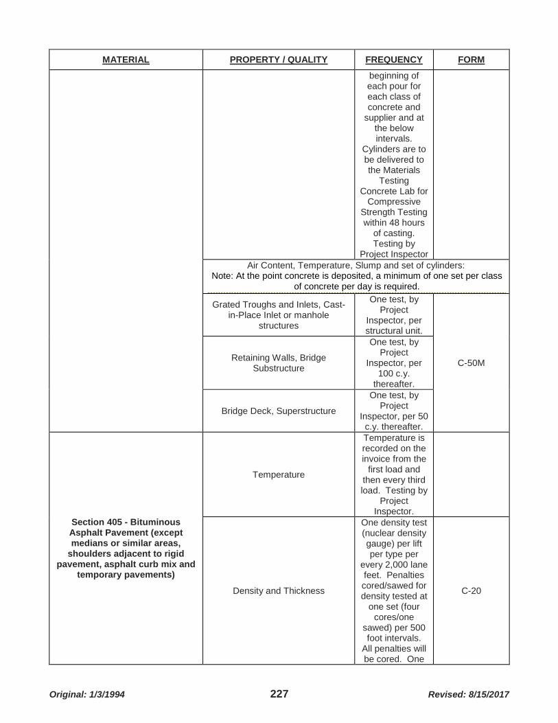
Original: 1/3/1994 227 Revised: 8/15/2017
MATERIAL PROPERTY / QUALITY FREQUENCY FORM
beginning of each pour for each class of concrete and
supplier and at the below intervals.
Cylinders are to be delivered to the Materials
Testing Concrete Lab for
Compressive Strength Testing within 48 hours
of casting. Testing by
Project Inspector Air Content, Temperature, Slump and set of cylinders:
Note: At the point concrete is deposited, a minimum of one set per class of concrete per day is required.
Grated Troughs and Inlets, Cast-in-Place Inlet or manhole
structures
One test, by Project
Inspector, per structural unit.
C-50M Retaining Walls, Bridge Substructure
One test, by Project
Inspector, per 100 c.y.
thereafter.
Bridge Deck, Superstructure
One test, by Project
Inspector, per 50 c.y. thereafter.
Section 405 - Bituminous Asphalt Pavement (except medians or similar areas,
shoulders adjacent to rigid pavement, asphalt curb mix and
temporary pavements)
Temperature
Temperature is recorded on the invoice from the
first load and then every third load. Testing by
Project Inspector.
Density and Thickness
One density test (nuclear density gauge) per lift per type per
every 2,000 lane feet. Penalties cored/sawed for density tested at
one set (four cores/one
sawed) per 500 foot intervals.
All penalties will be cored. One
C-20

Original: 1/3/1994 228 Revised: 8/15/2017
MATERIAL PROPERTY / QUALITY FREQUENCY FORM
set of cores taken per day for
density, thickness and composition.
Additional cores may be taken at
the Project Resident
Engineer's or assignee's discretion.
Testing performed by Materials Lab Field Section and Soils Lab.
All Pavement, Including New Subdivision Pavement > 26 feet wide:
Surface Tolerance
By 10 foot straightedge:
Parallel to centerline - ⅜
inch. Transverse construction
joints - ¼ inch. Testing
performed by Project
Inspector.
New Subdivision Pavement ≤ 26 feet wide:
Surface Tolerance
By 10 foot straightedge: Parallel and
Transverse - ½ inch. Testing by Project Inspector
Asphaltic Concrete Pavement (Superpave)
Temperature, Density, Surface Tolerance and Thickness
Same as for Bituminous Asphalt Pavement -See Contract
Documents
Microsurfacing Gradation, Binder Content
Before production, one
sample per stockpile by
Materials Lab Field Inspector
to Soil Lab. During
production one sample from behind paver during the first
day of production by
the Project
C-91

Original: 1/3/1994 229 Revised: 8/15/2017
MATERIAL PROPERTY / QUALITY FREQUENCY FORM
Inspector and then one sample every 5th day of
production. Sample
delivered to the Binder Lab by
the Project Inspector for
Extraction and gradation. See
Contract Documents.
Section 407 or 408 Tack or Prime In accordance with Section 1015
Project Inspector to submit one
quart sample per source per distributor delivery of
material, with certification, to
Binder Lab.
Section 604 Brick (On jobs with more than
100 pieces) Dimensions, absorption
Project Inspector to submit
sample of 5 bricks to
Concrete Lab for testing.
C-66
Section 706 Reinforcing Steel for Bridge, Box
Culvert, Retaining Wall Construction
(Tensile, Yield, Elongation, and Bend Tests)
Project Inspector to submit two bars from the
largest and the smallest sizes of
each heat number (36 inch in length). For
each heat number, one additional 36" long bar from each alternate size, beginning
with the smallest size bar. Project
Inspector to submit bar(s),
tagged with heat number, project
name and structure
location, with mill tests reports to Concrete Lab for testing on the 1st or 15th of the
month.
C-67

Original: 1/3/1994 230 Revised: 8/15/2017
MATERIAL PROPERTY / QUALITY FREQUENCY FORM
Section 726 Concrete and Clay Pipe
Field verify Condition, Classification
Project Inspector, for
each shipment of pipe, to
visually compare delivery invoice
to materials delivered
regarding pipe classification and condition
(cracks, exposed
reinforcement, etc.)
C-23
NOTES:
1) When aggregate base shown in the contract is to be measured and paid for by area, conversion of the area quantity to tons can be made by multiplying the thickness (in.) by the square yards of area covered by 0.06 tons/s.y./1” thickness.
2) When concrete shown in the contract is to measured and paid for by area, conversion of the area quantity to cubic yards (c.y.) can be made by multiplying the thickness (in.) by the square yards of area covered by 0.028 cy/sy/1” thickness.
3) Forms located in Materials Testing Laboratory Quality Control Manual.

Original: 1/3/1994 231 Revised: 8/15/2017
The following information establishes procedures for LPA Federal-Aid Acceptance Sampling and Testing (FAST) for all Federal-Aid projects awarded and administered by MoDOT. If a local public agency receives federal funds from MoDOT but does not specify, the guidelines in this Off-Systems Guide Schedule for Federal-Aid Acceptance Sampling and Testing (FAST) table should be followed. The acceptance sampling and testing procedures for other materials and construction processes are to be as shown in other articles in the Engineering Policy Guide.
TABLE 1017C – OFF-SYSTEMS GUIDE SCHEDULE FOR FEDERAL-AID ACCEPTANCE SAMPLING AND TESTING
Type of Construction
or Material Tests to be Made
(if specified) Sampled Minimum Number of Tests
Grading - Embankment Density/Moisture After compaction
A minimum of 4 density tests per day for each active grading spread regardless of road surface
Subgrade Preparation Density/Moisture After compaction
A minimum of 4 density tests per day for each active grading spread regardless of road surface
Aggregate Base1 Type 1, 5, 7 or Stabilized Permeable2 (roadway and shoulders)
Gradation Before compaction
One per 2000 tons or fraction thereof per specified gradation per source.
Density/Moisture After compaction
A minimum of 4 density and moisture tests per day for Type 1 and 5 aggregate and 4 penetration and moisture tests for Type 7 aggregate.
Plasticity Index Before compaction
One per project per specified gradation, per source.
Sand-Soil Base or Soil-Cement Base or Soil-Lime Base
Gradation Before compaction
One per 2000 tons or fraction thereof per specified gradation per source.
Density After compaction
A minimum of 4 density and moisture tests per day
Liquid Limit Before compaction
One per project per specified gradation, per source.
Plasticity Index Before compaction
One per project per specified gradation, per source.
Crushed Stone or Gravel Surfacing Gradation -
One per project per specified gradation, per source. Less than 500 tons accepted on certification.
Plant Mix Bituminous Base, Plant Mix Bituminous Pavement, or Asphaltic Concrete Pavement
Gradation Before mixing
One per 500 tons or fraction thereof per mix type. None required if mix type is less than 50 tons/day or 250 tons/project.
Density After compaction
2 roadway cores/day and 2 longitudinal unconfined joint cores/day < 100 tons. 4 roadway cores/day and 4 longitudinal unconfined joint

Original: 1/3/1994 232 Revised: 8/15/2017
Type of Construction or Material
Tests to be Made (if specified) Sampled Minimum Number
of Tests
cores/day ≥ 100 tons. Random Procedures per ASTM D 3665-07.
Asphalt Content Before compaction
One per day, using an approved AASHTO method for determining asphalt content.
PCC Pavement or PCC Base
Gradation (both coarse and fine aggregates) Batch plant
One per 2000 cubic yards or fraction thereof per specified gradation, per source.
Deleterious (coarse aggregate) Batch plant
One per 2000 cubic yards or fraction thereof per specified gradation, per source.
Air Content/Slump Jobsite
Air and consistency tests are to be made at the beginning of each pour and for each 100 cubic yards/mix design/pour/day thereafter.
Compressive Strength Jobsite
One set of specimens should be made at the beginning of each pour and every 100 cubic yards/mix design/pour/day thereafter. 4
Concrete Masonry Structural items including but not limited to: Bridges, CIP retaining walls, box culverts, bolted-down footings
Gradation (both coarse and fine aggregates) Batch plant
One per 1000 cubic yards or fraction thereof per specified gradation, per source.
Deleterious (coarse aggregate) Batch plant
One per 1000 cubic yards or fraction thereof per specified gradation, per source.
Air Content/Slump Jobsite
Air and consistency tests are to be made at the beginning of each pour and for each 100 cubic yards/mix design/pour/day thereafter.
Compressive Strength Jobsite
One set3 of specimens should be made at the beginning of each pour and every 100 cubic yards/mix design/pour/day thereafter. 4
Concrete Masonry: Incidental Concrete (curb & gutter, sidewalk, etc.).
Gradation (both coarse and fine aggregates) Batch plant
One per 1000 cubic yards or fraction thereof per specified gradation, per source.
Deleterious (coarse aggregate) Batch plant
One per 1000 cubic yards or fraction thereof per specified gradation, per source.
Air Content/Slump Jobsite
Air and consistency tests are to be made at the beginning of each pour and for each 100 cubic yards/mix design/pour/day thereafter.
Compressive Strength Jobsite One set3 of specimens should be made at the beginning of each pour

Original: 1/3/1994 233 Revised: 8/15/2017
Type of Construction or Material
Tests to be Made (if specified) Sampled Minimum Number
of Tests
and every 100 cubic yards/mix design/pour/day thereafter when the total quantity on the concrete tickets per mix design is ≥ 3cy.5
Precast Items Gradation/Deleterious/Air Content/Slump
Manufacture Plant
Obtain plant certification when using MoDOT approved plant otherwise quality plan will need to be submitted.
Coating of Structural Steel6
Environmental Conditions/Surface Profile/Mil Thickness
Jobsite One test/day as it applies for working being performed
1 When aggregate base shown in the contract is to be measured and paid for by area, convert the area to tons and follow the sampling frequency shown in this table. When converting, use the factor .06 tons/sq. yd./1 in. thickness of compacted base. 2 Gradation only for Type 4 and Stabilized Permeable Base. 3 One set of cylinders shall consist of 2 - 6” x 12” cylinder molds or 3 - 4” x 8” cylinder molds. To determine if ultimate (contractual) strength has been obtained, one set of cylinders must be tested and the average strength of all cylinders will determine ultimate strength of in place concrete. 4 Air and slump tests are required for each set of cylinders created. 5 Compressive strength test can be waived if the concrete to be placed in any one day is less than 3 C.Y. and an air, slump, and compressive strength test was performed the preceding day on that class of concrete. 6 Painting contractor is required to be part of certification program such as NACE, SSPC or equivalent.

Original: 1/3/1994 234 Revised: 8/15/2017
TABLE 1017D - COMMON CONSTRUCTION MATERIALS REQUIRING CERTIFICATIONS
Section Material Certified Test Results Remarks
Section 403 Geosynthetic Material Section 1011.3.7, 1011.3.8, or 1011.3.9
As Specified in Contract Documents
Section 407, Tack Coat Emulsified Asphalt (CPEM-1, SS-1, SS-1H, CSS-1, or CSS-H)
Section 1015 Test Samples May be Required
Section 408, Prime Coat
Type MC Liquid Asphalt Section 1015 Test Samples May be Required
Emulsified Asphalt (CPEM-1, SS-1, SS-1H, CSS-1, or CSS-H)
Section 1015 Test Samples May be Required
Section 603 Miscellaneous Water Equipment
Seamless Copper Water Tube ASTM B88 Type K
Section 701 Drilled Shafts Casings ASTM A252 Grade 2
Section 702 Bearing Pile Structural Steel Pile Section 702.2.6 Structural Steel Thick Shells for Cast-In Place Section 702.2.6
Section 706 Reinforcing Steel for Concrete Structures
Mechanical Bar Splice Systems Section 706.3.3 Test Samples
May be Required
Section 802, Mulching Mulch Section 802.2.2 Section 806, Pollution, Sediment, and Erosion Control
Temporary Erosion Control Blanket Section 1011.3.6
Section 904 Traffic Control Facilities
Controller Cabinet Equipment
NEMA Standards Publication No. TS 2 Type 2 Traffic Control Systems
Section 1011 Geotextile Geotextiles AASHTO M288, MARV
Section 1012 Geocomposite Drainage Material
Edge Drain Section 1012.3.2
Vertical Drain at End Bent Section 1012.3.3
Section 1013, Miscellaneous Drainage Material
Corrugated Polyvinyl Chloride Pipe ASTM F949
Smooth Wall Polyvinyl Chloride Pipe ASTM D3034
Schedule 40 Polyvinyl Chloride Pipe ASTM D1785
Corrugated High Density Polyethylene Pipe
AASHTO M252 Type S or SP
Corrugated Double Wall Polypropylene Pipe ASTM 2736
Corrugated Triple Wall Polypropylene Pipe ASTM F2764
Section 1020, Corrugated Metallic Coated Steel Culvert Pipe, Pipe Arches, and End Sections
Corrugated Metallic Coated Steel Culvert Pipe, Pipe Arches, and End Sections
Section 1020

Original: 1/3/1994 235 Revised: 8/15/2017
Section Material Certified Test Results Remarks
Section 1022, Corrugated Metallic Coated Steel Pipe Underdrain
Corrugated Metallic Coated Steel Pipe Underdrain
AASHTO M36 Type III
Section 1026, Reinforced Concrete Culvert, Storm Drain and Sewer Pipe
Reinforced Concrete Culvert, Storm Drain and Sewer Pipe
AASHTO M170
Type A Rubber Gaskets AASHTO M198
Section 1036, Reinforcing Steel for Concrete
Deformed Bars Section 1036.3.1 Test Samples May be Required
Steel Welded Wire Reinforcement ASTM A1064 Test Samples
May be Required Section 1037 Shear Connectors Studs Section 1037
Section 1038, Bearing Pad for Structures
Elastomeric Bearing Pads Section 1038.3 Type "N" Polytetrafluoroethylene Bearing Pads
Section 1038.4
Rubber and Fabric Pads Section 1038.5
Rubber and Fiber Pads Section 1038.6
Section 1039 Epoxy Resin Material
Epoxy or Polyester Resin for Dowels Section 1039.30
Epoxy Bonding Agents for Resin Anchor Systems Section 1039.40
Polymer Concrete Section 1039.70
Section 1040, Guardrail, End Terminals, One-Strand Access, Restraint Cable, and Three Strand Guard Cable Material
Wood Post and Blocks Section 1040.2
Steel Beam Guard Rail Section 1040.3
Crashworthy End Terminal Section 1040.4 End Anchors and Bridge Anchors Section 1040.5
Cable and Fittings Section 1040.6
Section 104, Polypropylene Culvert Pipe
Polypropylene Culvert Pipe Double Walled ASTM F2736
Polypropylene Culvert Pipe Triple Walled ASTM F2764
Section 1043, Fence Material
Fabric Section 1043.2 Post, Braces, Rails, and Gate Frame Section 1043.2.5
Section 1045, Paint for Structural Steel Coating and Primer Section 1045
Section 1048, Pavement Marking Material
Preformed Removable Pavement Marking Tape Section 1048.4
Drop On Glass Beads Section 1048.6
Temporary Lane Markers Section 1048.7 Acrylic Copolymer Fast Drying Pavement Marking Section 1048.11

Original: 1/3/1994 236 Revised: 8/15/2017
Section Material Certified Test Results Remarks
Paint
Acrylic Waterborne Pavement Marking Paint Section 1048.12
Section 1052, Mechanically Stabilized Earth Wall System
Geogrid Section 1052.3.1 Small Block Wall System- Concrete Blocks Section 1052.5
Section 1053, Penetrating Protective Sealer Material Section 1054, Concrete Admixtures
Penetrating Protective Sealer Material Section 1053.3
Air entraining Admixture Section 1054.3.2
Water Reducing Admixture Section 1054.4.2 Non-Chloride Accelerating Admixture
AASHTO M194 Type C or E
Chloride Accelerating Admixture AASHTO M144
Section 1055, Concrete Curing Material
Type 1-D Curing Compound Section 1055.4.2.3.1
Type 2-D Curing Compound Section 1055.4.2.3.2
Dissipating Curing Compounds Section 1055.4.2.3.3
Section 1057, Material for Joints
Corrosion-Resistant Coated Dowel Bars
AASHTO M254, Type B (ASTM A615) Grade 40 or Grade 60
Joint and Crack Sealer, Hot Poured Elastic Type Section 1057.5 Test Samples
May be Required Preformed Fiber Expansion Joint Filler Section 1057.5.2
Backer Material Used with Cold and Hot-Applied in Portland Cement and Asphalt Joints
Section 1057.5.3
Polyurethane Elastomeric Joint Sealer Section 1057.6
Polyvinyl Chloride Water Stop Section 1057.7.1
Rubber Water Stop Section 1057.7.2 Preformed Sponge Rubber Expansion and Partition Joint Filler
Section 1057.7.4
Silicone Expansion Joint Sealer Section 1057.10
Silicone Joint Sealant for Sawcut and Formed Joints Section 1057.11
Section 1080 Structural Steel Fabrication
Structural Steel Section 1080.2.4 High Strength Fastener Assembly Section 1080.2.5

Original: 1/3/1994 237 Revised: 8/15/2017
NOTES: