engineering transactions engng. trans. 55, 3, 197–216...
TRANSCRIPT

ENGINEERING TRANSACTIONS • Engng. Trans. • 55, 3, 197–216, 2007Polish Academy of Sciences • Institute of Fundamental Technological Research
FINITE ELEMENT ANALYSIS OF STRAIN NON-UNIFORMITY IN TWOPROCESSES OF SEVERE PLASTIC DEFORMATION
J. M a c i e j e w s k i, H. K o p e ć, H. P e t r y k
Institute of Fundamental Technological Research
Polish Academy of Sciences
Warsaw, Poland
Two severe plastic deformation (SPD) processing techniques, namely equal-channel angularpressing (ECAP) and cyclic extrusion-compression (CEC), are investigated by using the finiteelement method. The major aspect examined is the non-uniformity of the accumulated, equiv-alent plastic strain after processing with the use of different shapes of the die. The quantitativeeffect of several parameters on the plastic flow is determined. It is found that the diameter ratioof the chambers and narrower channel in the CEC method, and also the inclination angle ofconnecting conical parts, can affect strongly the degree of strain non-uniformity. Comparisonis made of distributions of equivalent strain after two passes of ECAP for two different routesand with two die profiles.
1. Introduction
In the last two decades many studies have been devoted to the materialprocessing by applying severe plastic deformation (SPD). The principal aim ofimposing extremely large plastic strains is to achieve ultra-fine grain sizes. De-crease of grain size to a sub-micrometer level is related to beneficial mechanicalproperties such as very high strength which may also be accompanied by low-temperature superplasticity. In contradistinction to traditional cold rolling orextrusion, the purpose of SPD is not to reduce a cross-section dimension to agiven value. Several SPD processes have been designed so that the billet shape re-mains essentially unchanged after the processing by cyclic deformation. Two suchprocesses are investigated here, namely, equal-channel angular pressing (ECAP)and cyclic extrusion-compression (CEC). ECAP is the most popular SPD tech-nique, introduced in the former Soviet Union [1]. An extensive review of the vastliterature and recent developments related to the use of ECAP for grain refine-ment can be found in Ref. [2]. CEC is the SPD technique developed in Poland[3] and subsequently studied in a series of papers, e.g. [4–7].
Majority of papers dealing with SPD techniques have concentrated on micro-structural aspects of the grain refinement and on the changes in mechanical prop-

198 J. MACIEJEWSKI, H. KOPEĆ, H. PETRYK
erties of the material. Modelling of the material flow was also performed by usingan analytic approach [8–10], the slip-line field theory [11, 12], an upper-boundapproach [13, 14], and the finite element method (FEM) [15–23], predominantlyfor ECAP. The present authors are aware of the only one finite element study ofthe CEC process [17].
The aim of this paper is to present selected results of FEM simulations ofthe above-mentioned two SPD processes. The axisymmetric FEM simulationsof CEC and plane-strain simulations of ECAP have been performed by usingthe commercial computer code ADINA [24]. The modelling of CEC constitutesthe major part of this work and provides new results. ECAP was thoroughlystudied in the literature, nevertheless the present analysis of two passes for twodifferent ECAP routes and two die profiles and for different friction conditions,appears to be novel. The major aspect examined below is the non-uniformityof the accumulated, equivalent plastic strain after processing with the use ofdifferent shapes of the die. The predictions of numerical simulations can help inoptimal design of the tools for technological applications.
2. Simulations of cyclic extrusion-compression (CEC)
2.1. Description
The cyclic extrusion-compression method can be applied to achieve unlimitedaccumulated strains by a combination of the processes of extrusion and compres-sion, with preservation of the initial shape of a material sample [3–7]. This isan important advantage of the CEC method. The sample (Fig. 1) is placed inthe die consisting of left and right chambers of equal diameter d0, connectedby a channel of a smaller diameter dm. The deformation proceeds by the cyclicflow of metal from one chamber to the other. For example, in a single cycle thesample is extruded from the left chamber, say, by the left active punch, withthe backpressure exerted by the right passive punch which causes plastic com-pression of the material just after extrusion. In the next cycle, the right punchbecomes active and the deformation proceeds by flow of the sample from the
Fig. 1. Sketch of CEC deformation process.

FINITE ELEMENT ANALYSIS OF STRAIN NON-UNIFORMITY ... 199
right chamber to the left, and so on. In this way the metal sample is deformedcyclically to unlimited strains without removing the material sample from theapparatus. If the deformation is assumed to be uniform, then the magnitude ofthe accumulated equivalent (von Mises) strain after ndeformation cycles can beestimated as follows [3]:
(2.1) ε = 4n ln
(
d0
dm
)
.
The FEM simulations of the CEC process were performed using theADINA 8.3 System, assuming axisymmetric deformation and large strain andlarge displacement kinematics under isothermal and quasistatic conditions. Afinite element mesh covering the deformed material consisted of 2240 axisym-metric 9-node solid elements. The die and the punches were modelled as rigidbodies. Figure 2 presents the scheme of the FE mesh and of the die shape. In thenumerical analysis the die shape was described by parameters: d0, dm, α inclina-tion angle of the conical parts) and a (length of the central cylindrical channel).The transition from the cylindrical to conical parts of the die was modelled as acurve of radius R = 1/2 (d0 − dm).
Fig. 2. Scheme of the finite element mesh and CEC channel geometry.
In the calculations the material was modelled as elastic-plastic with isotropichardening described by a multilinear approximation of a true (logarithmic) strain– true (Cauchy) stress curve shown in Fig. 3. The experimental data pointsthat correspond to polycrystalline pure aluminium (99.99%) deformed at roomtemperature (293 K) in a wide range of strain are taken from Refs. [25]. Theexperimental data for low strain level were obtained in the tension test, whereasfor larger strains the data were reported for samples produced in the ECAPprocess [26, 27]. The elasticity parameters were taken as Young’s modulus E =70 GPa and Poisson’s ratio ν = 0.32.

200 J. MACIEJEWSKI, H. KOPEĆ, H. PETRYK
Fig. 3. Experimental data points [25–27] and a multilinear approximation of the truestress–true strain curve for a wide range of strain for pure Al deformed at room
temperature (293 K).
In the real CEC process the samples were covered with a graphite lubricantbefore the deformation process [5]. In the calculation, the frictionless contact aswell as the nonlinear friction model were used. The nonlinear friction law wasassumed in the form
(2.2) τn = A1 (1 − exp(−σnA2)) ,
where τn, σn are the shear and normal contact stress components, respectively,and A1, A2 are the friction parameters whose meaning is indicated in Fig. 4.
Fig. 4. The nonlinear friction law used in numerical simulations.

FINITE ELEMENT ANALYSIS OF STRAIN NON-UNIFORMITY ... 201
Two different sequences of calculation of the CEC process have been used
(Fig. 5). In the first sequence illustrated in Fig. 5a, the material was initially in
the left chamber only. As the left punch was kinematically forced to move, the
forward extrusion (without the passive punch) was executed. Next the pressure
was applied to the right punch, aimed at complete filling of the die space, while
the active left punch was still moving. As a result, a roughly uniform deformation
zone around the sample axis in the central part was obtained. In the end zone
of the sample the strain distribution was non-uniform. In the second sequence
of calculation, the initial material position was as shown in Fig. 5b. The right-
hand side of the sample was positioned at once beyond the narrower channel, the
hardening effect of compression by the right-hand punch being neglected. Then,
along with the active left punch motion, the backpressure was exerted by the
right punch. After completing the first cycle of deformation, the resulting strain
distributions were found to be of steady-state type and practically the same for
both calculation sequences, except in the vicinity of the right end of the sample.
Therefore, in further calculations only the second sequence was used as a simpler
approach.
Fig. 5. Equivalent plastic strain field in the subsequent phases of the first pass in CECprocess for two different sequences of calculation: a) initial position of the sample in the left
chamber only, b) initial position of the sample covers the central channel.

202 J. MACIEJEWSKI, H. KOPEĆ, H. PETRYK
2.2. Results and discussion
Figure 6 shows the distribution of accumulated equivalent plastic strain in thetransverse cross-section of the sample after the first cycle of the CEC processfor different diameter ratios d0/dm = 15/11, 10/8, 10/9, 10/9.5. The resultswere taken from for the major (central) part of the sample where the strain wasuniform along the axis. In this calculation, a frictionless contact was assumedand the additional shape parameters were: inclination angle of conical partsα = 25◦ and channel length a = 2mm. The dashed lines in the figure representthe theoretical magnitude of accumulated equivalent plastic strain after one cyclewhich, according to Eq. (2.1), is equal to 1.24, 0.982, 0.421, 0.20 for diameterratio d0/dm =15/11, 10/8, 10/9, 10/9.5, respectively. It is clearly seen that thedeformation is non-uniform with the peak near the outer radius of the sample,with a strong influence of the diameter ratio on the strain non-uniformity. Forthe dies with diameter ratio 10/9 and 10/9.5, the accumulated equivalent strainnear the sample axis is less than the theoretical value. The strain distribution isfairly uniform for d0/dm = 15/11.
Fig. 6. Accumulated equivalent plastic strain versus the sample radius after one cycle of theCEC process, with different diameter ratios d0/dm = 15/11, 10/8, 10/9, 10/9.5. Channel
length a = 2 mm, inclination angle of conical parts α = 25◦, frictionless conditions.
The angle of inclination of conical parts of the die has also a significant influ-ence on the resulting homogeneity of the sample. The variation of accumulatedequivalent plastic strain with respect to the sample radius for different inclina-

FINITE ELEMENT ANALYSIS OF STRAIN NON-UNIFORMITY ... 203
tion angles α = 15◦, 25◦, 35◦, 45◦ is presented in Fig. 7. These calculations wereperformed for diameter ratio d0/dm = 10/8 and channel length a = 2 mm. Withthe angle growth, the non-homogeneity increases.
Fig. 7. Accumulated equivalent plastic strain versus the sample radius after one cycle of theCEC process, with d0/dm = 10/8 and channel length a = 2 mm, for different inclination
angles α = 15◦, 25
◦, 35◦, 45
◦ of conical parts of the die.
Fig. 8. Accumulated equivalent plastic strain versus the sample radius after 1 cycle of theCEC process, with d0/dm = 10/8 and α = 25
◦, for different channel lengths a = 0, 2, 4 mm.

204 J. MACIEJEWSKI, H. KOPEĆ, H. PETRYK
The influence of the length a of the cylindrical channel of the die is lesssubstantial as that shown in Fig. 8. The non-homogeneity is the largest forchannel length a = 0 when the conical parts of the die are in contact.
Figure 9 shows the effect of friction on the material/tool contact surface, onthe radial distribution of accumulated equivalent plastic strain. In the case ofdiameter ratio 10/9 and inclination angle of conical parts α = 25◦, the influenceof friction was significant only near the outer surface being in contact with thetool, whereas in the remaining part the deformation was only slightly affectedby friction.
Fig. 9. Accumulated equivalent plastic strain distribution for different friction parameters.
The next three figures show perhaps the most important effect of the ratio ofthe chamber and channel diameters on the plastic strain non-uniformity. Eachfigure corresponds to the same values of channel length and inclination angle ofconical parts, taken in this case as a = 2 mm and α = 25◦, respectively, whilethe diameter ratio is the only variable parameter. Frictionless contact has beenassumed. In Fig. 10 the radial distribution of the accumulated equivalent plasticstrain is shown after the first, second and third cycle of CEC, for diameter ratio10/8. The distribution is clearly not uniform, but the degree of non-uniformity(ratio of maximum to minimum equivalent strains) equal to 1.7 does not increaseafter subsequent cycles. Therefore, in the range of severe plastic deformationwhere the strain hardening saturates, that strain non-uniformity does not needto lead to substantial macroscopic heterogeneity in the mechanical propertiessuch as the yield stress or microhardness. If fact, the microhardness distributions

FINITE ELEMENT ANALYSIS OF STRAIN NON-UNIFORMITY ... 205
along the sample diameter, after 4 and 22 cycles of CEC with the die of diameter,ratio 10/8, were found to be fairly uniform and close to each other [3].
Fig. 10. Accumulated equivalent plastic strain after 1, 2 and 3 cycles of the CEC process,with d0/dm = 10/8, a = 2 mm and α = 25
◦; a) distribution versus the sample radius,b) 2D distribution in the longitudinal cross-section.
The situation changes when the difference in diameter of the chambers andthe connecting channel is too small. As shown in Figs. 11 and 12, in that casethe degree of non-uniformity is large and increases with subsequent cycles to9.7 and 40, for the diameter ratio d0/dm= 10/9 and 10/9.5, respectively. The

206 J. MACIEJEWSKI, H. KOPEĆ, H. PETRYK
Fig. 11. Accumulated equivalent plastic strain versus the sample radius after 1, 2 and 3cycles of the CEC process, with d0/dm =10/9.
Fig. 12. Accumulated equivalent plastic strain versus the sample radius after 1, 2 and 3cycles of CEC, with d0/dm =10/9.5.
equivalent strain in the inner part of the sample, deformed when using the dieof diameter ratio d0/dm =10/9 is accumulated much slower than that predictedby the formula (2.1) for uniform distribution of strain, while in the outer partit becomes much larger. If the diameter ratio d0/dm is smaller, then the plasticstrain accumulation in the inner part may even be suspended, cf. Fig. 12.
FINITE ELEMENT ANALYSIS OF STRAIN NON-UNIFORMITY ... 207
It may be noted that the above conclusion has been drawn from the numer-ical results obtained by using the conventional plasticity model, which does notdescribe the formation of macroscopic shear bands. Such bands running acrossthe sample were observed experimentally [4, 6]. Presence of macroscopic shearbands, while introducing local flow non-uniformities, might nevertheless reducethe strain non-uniformity on the scale of the sample radius. This question re-quires further study which is, however, beyond the scope of the present paper.
3. Simulations of equal-channel angular pressing (ECAP)
3.1. Description
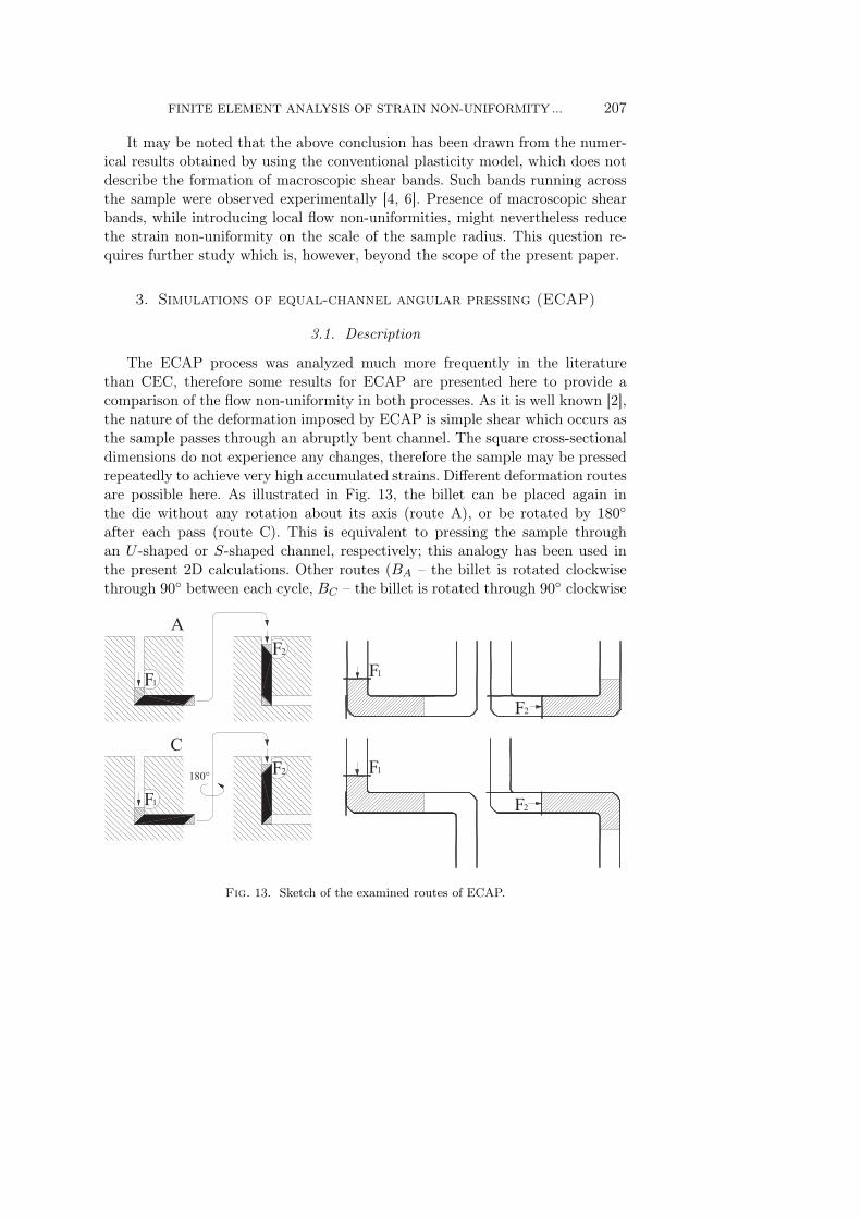
The ECAP process was analyzed much more frequently in the literaturethan CEC, therefore some results for ECAP are presented here to provide acomparison of the flow non-uniformity in both processes. As it is well known [2],the nature of the deformation imposed by ECAP is simple shear which occurs asthe sample passes through an abruptly bent channel. The square cross-sectionaldimensions do not experience any changes, therefore the sample may be pressedrepeatedly to achieve very high accumulated strains. Different deformation routesare possible here. As illustrated in Fig. 13, the billet can be placed again inthe die without any rotation about its axis (route A), or be rotated by 180◦
after each pass (route C). This is equivalent to pressing the sample throughan U -shaped or S-shaped channel, respectively; this analogy has been used inthe present 2D calculations. Other routes (BA – the billet is rotated clockwisethrough 90◦ between each cycle, BC – the billet is rotated through 90◦ clockwise
Fig. 13. Sketch of the examined routes of ECAP.

208 J. MACIEJEWSKI, H. KOPEĆ, H. PETRYK
and then 90◦ anticlockwise each alternate cycle) are not examined here sincethey would require a more complex 3D analysis.
Details of die geometry have a certain influence of the material flow throughthe die. In this paper, two types of die geometry have been investigated, asshown in Fig. 14. Such dies with the angle of intersection of the channels equalto φ = 90◦ and with the angle of the outer arc of curvature where the twochannels intersect, equal either to ψ = 20◦ or ψ = 0◦, are typical in applications[2]. The radius r of rounded-off corners is introduced here mainly to overcomenumerical problems related to simulation of plastic flow around sharp corners.The finite element mesh consisted of 5472 plane-strain 9-node elements; its partis shown in Fig. 15.
Fig. 14. Geometry of two ECAP dies used in numerical simulations.
The material model used in calculations corresponds to pure aluminium asin CEC calculations, however, with two modifications. First, hardening was de-scribed here in a more simple way by assuming linear hardening from the initialyield stress σ0 = 95 [MPa] with the tangent modulus ET = 15 [MPa]. Eitherpure isotropic or pure kinematic hardening were examined.
3.2. FEM results and discussion
Figure 15 shows the distribution of the accumulated equivalent plastic strainin the longitudinal cross-section of the sample in the vicinity of the basic shearzone, together with the distribution of contact surface tractions, for four valuesµ = 0.01, 0.1, 0.2, 0.3 of the assumed Coulomb friction coefficient. It has beenfound that while the value of µ does not influence the strain distribution exceptin the surface layer, it affects the length of the outer corner gap identified asa zone where the surface tractions are zero.

FINITE ELEMENT ANALYSIS OF STRAIN NON-UNIFORMITY ... 209
Fig. 15. Distribution of equivalent plastic strain and of surface tractions during the firstpass through Die I, for different values µ = 0.01, 0.1, 0.2, 0.3 of the Coulomb frictioncoefficient. The development of the corner gap is dependent on the friction conditions.
In Fig. 16a the force acting on the punch during the first and second pass,using Die I for route C, is plotted versus the punch displacement for differentvalues of the Coulomb friction coefficient. In Fig. 16b the respective distribu-tions of equivalent plastic strain across the billet are presented. The formingforce grows with increasing friction coefficient as expected, whereas the distri-butions of equivalent plastic strain are very similar for different friction coef-ficients. Small differences in the sub-surface layers of the billet are only ob-served.

210 J. MACIEJEWSKI, H. KOPEĆ, H. PETRYK
Fig. 16. Simulation results for ECAP Route C using Die I for different values µ = 0.1,0.2, 0.3 of the Coulomb friction coefficient, a) force acting on the punch versus the punch
displacement, b) distribution of equivalent plastic strain across the billet.
In Fig. 17 the longitudinal distribution of equivalent plastic strain after thefirst pass through the ECAP Dies I and II is shown first, followed by similarpictures after the second pass according to routes A and C. It can be seen thatthe strain distribution is more non-uniform after the second pass for route Athan that for C, which is more clearly visible for Die I. In turn, the distributionof equivalent plastic strain is found more uniform for Die I with ψ = 0◦ than thatfor Die II with ψ = 20◦. During a passage through Die II, a less deformed layer isformed in the lower part of the sample. After a closer look at the deformed mesh,a conclusion can be drawn that this is due to formation of a rotating and lessdeforming zone, in vicinity of the rounded outer corner of Die II. The obtainedresults are in qualitative agreement with previous studies [9, 11, 20, 28, 29].A more detailed plots of the distributions of equivalent plastic strain across thematerial sample are shown in Fig. 18.

FINITE ELEMENT ANALYSIS OF STRAIN NON-UNIFORMITY ... 211
Fig. 17. The fields of equivalent plastic strain during ECAP, after the first and second passthrough Die I and II for routes A and C.

212 J. MACIEJEWSKI, H. KOPEĆ, H. PETRYK
Fig. 18. Distribution of equivalent plastic strain across the billet during ECAP, after thefirst and second pass through Dies I and II, for routes A and C.
The difference between the deformation fields calculated for isotropic hard-ening and for kinematic hardening, corresponding to the same stress-strain curvefor monotonic loading and for the same ECAP conditions, has not been foundto be significant. A more essential and expected difference appears between theplots of the total force acting on the punch during the second pass accordingto route C, cf. Fig. 19. The reason for the difference is clear as for this routethe direction of shear is reversed, which corresponds to the decrease of the shearstress when kinematic rather than isotropic hardening is assumed.

FINITE ELEMENT ANALYSIS OF STRAIN NON-UNIFORMITY ... 213
Fig. 19. Force acting on the punch versus the punch displacement during the second pass ofECAP, using Die II with negligible friction (µ = 0.01). The results are for routes A and C
and for either isotropic or kinematic hardening.
4. Conclusions
Finite Element Method simulations of the CEC and ECAP processes havebeen carried out for the elastoplastic material with strain hardening under isother-mal conditions. The model parameters were calibrated for polycrystalline purealuminium (99.99%) at room temperature.
The CEC process was simulated for various die shape parameters: ratiod0/dm (of diameters of the chambers and central cylindrical channel of the die,respectively), α (inclination angle of conical parts that connect chambers withthe channel) and a (length of the cylindrical channel). The diameter ratio d0/dm
is the most important parameter which determines the overall magnitude ofstrain in a single pass. The simulations performed have shown that the defor-mation is always non-uniform, with a peak near the outer radius of the sample.However, the degree of non-uniformity, defined as the ratio of maximum to min-imum equivalent strain along the sample radius, is found to depend strongly onthe value of d0/dm.
For dies with diameter ratio 10/9.5 and 10/9 the accumulated equivalentstrain near the sample axis is much less than the theoretical value for uniformdeformation, and the degree of non-uniformity is large and increases with sub-sequent cycles. If the diameter ratio d0/dm is too small then the plastic strainaccumulation in the inner part may even be suspended, as it happened for the die10/9.5 with the other parameters provided in Fig. 12. With the increase of the

214 J. MACIEJEWSKI, H. KOPEĆ, H. PETRYK
diameter ratio the deformation becomes more uniform, and for diameter ratio10/8 the degree of non-uniformity equal to 1.7 does not increase after subse-quent cycles. Equivalent plastic strain distribution is found to be fairly uniformfor somewhat higher diameter ratio (15/11), with the degree of non-uniformityreduced to 1.2. The above conclusions have been drawn using the conventionalplasticity model which does not describe formation of macroscopic shear bandsobserved experimentally.
The angle of inclination of conical parts of the die has also a significantinfluence on the resulting homogeneity of the sample, and with the angle growththe non-homogeneity increases. By decreasing the inclination angle at a fixedvalue of d0/dm, homogeneity of the deformation can be substantially improved.The influence of length a of the central cylindrical channel of the die is lesssubstantial.
Friction on the material/tool contact surface has a considerable influence onthe strain peak near the outer surface being in contact with the tool, whereas incentral part the deformation it is found to be only slightly affected by friction.
Finite Element simulations of two passes of the ECAP process were carriedout for routes A and C using two die shapes and for different friction conditions.
It is found that the value of the Coulomb friction coefficient µ does notinfluence the strain distribution except in the sub-surface layers, although thevalue of µ affects the length of the outer corner gap identified as a zone wherethe surface tractions are zero.
A uniform region of equivalent plastic strain accumulated in the first andsecond pass of ECAP is obtained in the central part of the billet. The straindistribution after the second pass is more non-uniform for route A than forroute C, especially for Die I. In turn, the distribution of equivalent plastic strainis found to be more uniform for Die I with ψ = 0◦ than for Die II with ψ = 20◦.During a passage through Die II, a less deformed layer is formed near the outercorner of the die.
Acknowledgment
This work has been supported by the State Committee for Scientific Research(KBN) in Poland through Grant No. PBZ-KBN-096/T08/2003.
References
1. V.M. Segal, Materials processing by simple shear, Mater. Sci. Eng. A, 197, 157–164,1995.
2. R.Z. Valiev, T.G. Langdon, Principles of equal-channel angular pressing as a process-ing tool for grain refinement, Progress in Materials Science, 51, 881–981, 2006.

FINITE ELEMENT ANALYSIS OF STRAIN NON-UNIFORMITY ... 215
3. J. Richert, M. Richert, A new method for unlimited deformation of metals and alloys,Aluminium, 8, 604–607, 1986.
4. M. Richert, A. Korbel, The Effect of strain localization on mechanical properties ofAl99,992 in the range of large deformations, J. Mater. Proc. Technol., 53, 331–340, 1995.
5. M. Richert, J. Richert, J. Zasadzinski, H. Dybiec, The boundary strain hardeningof aluminium with unlimited cumulation of large deformation, Z. Metallkd., 79, 741, 1988.
6. M. Richert, Q. Liu, N. Hansen, Microstructural evolution over a large strain range inaluminium deformed by cyclic extrusion–compression, Materials Science and EngineeringA, 260, 275–283, 1999.
7. M. Richert, H.P. Stuwe, M.J. Zehetbauer, J. Richert, R. Pippan, Ch. Motz, E.
Schafler, Work hardening and microstructure of AlMg5 after severe plastic deformationby cyclic extrusion and compression, Materials Science and Engineering A, 355, 180–185,2003.
8. L. Dupuy, E.F. Rauch, Deformation paths related to equal channel angular extrusion,Materials Science and Engineering A, 337, 241–247, 2002.
9. I. J. Beyerlein, C. N. Tome, Analytical modeling of material flow in equal channelangular extrusion (ECAE), Materials Science and Engineering A, 380, 171–190, 2004.
10. C. Liu, D.J. Alexander, A kinematic analysis of the angular extrusion (AE) operationsMaterials Science and Engineering A, 391, 198–209, 2005.
11. V.M. Segal, Equal channel angular extrusion: from macromechanics to structure forma-tion, Materials Science and Engineering A, 271, 322–333, 1999.
12. V.M. Segal, Slip line solutions, deformation mode and loading history during equal chan-nel angular extrusion, Materials Science and Engineering A 345, 36–46, 2003.
13. J. Alkorta, J.G. Sevillano, A comparison of FEM and upper-bound type analysisof equal-channel angular pressing (ECAP), Journal of Materials Processing Technology,141, 313–318, 2003.
14. B.S. Altan, G. Purcek, I. Miskioglu, An upper-bound analysis for equal-channelangular extrusion, Journal of Materials Processing Technology, 168, 137–146, 2005.
15. P.B. Prangnell, C. Harris, S.M. Roberts, Finite element modelling of equal-channelangular extrusion, Scripta Mater., 37, 983–989, 1997.
16. H.S. Kim, M.H. Seo, S.I. Hong, On the die corner gap formation in equal channelangular pressing, Materials Science and Engineering A, 291, 86–90, 2000.
17. A. Rosochowski, R. Rodiet, P. Lipiński, Finite element simulation of cyclicextrusion-compression, Metal Forming 2000, Pietrzyk et al. [Eds.], 253–259, 2000.
18. A. Rosochowski, L. Olejnik, Numerical and physical modelling of plastic deformationin 2-turn equal channel angular extrusion, Journal of Materials Processing Technology,125–126, 309–31, 2002.
19. C.J. Luis Pérez, P. González, Y. Garcés, Equal channel angular extrusion in acommercial Al–Mn alloy, Journal of Materials Processing Technology, 143–144, 506–511,2003.
20. S. Li, M.A.M. Bourke, I.J. Beyerlein, D.J. Alexander, B. Clausen, Finite ele-ment analysis of the plastic deformation zone and working load in equal channel angularextrusion, Materials Science and Engineering A, 382, 217–236, 2004.