engineering manual - lg vrf alternative method of cooling and heating in commercial struc- ......
TRANSCRIPT

EnginEEring Manual
Variable Refrigerant Flow Outdoor Unit4.4 Tons

VRF-EM-BS-001-US_014A15
For continual product development, LG Electronics U.S.A., Inc., reserves the right to change specifications without notice. ©LG Electronics U.S.A., Inc.
ProPriEtary Data noticEThis document, as well as all reports, illustrations, data, information, and
other materials is the property of LG Electronics U.S.A., Inc., and are disclosed by LG Electronics U.S.A., Inc., only in confidence.
This document is for design purposes only.

Due to our policy of continuous product innovation, some specifications may change without notification. 3
introduction
about lg Electronics, inc.LG Electronics, Inc. is a global leader and technology innovator in consumer electronics, mobile communications, and home appliances. LG Electronics comprises four business units—Home Entertainment, Mobile Communications, Home Appliance, and Air Conditioning and Energy Solutions. LG is one of the world’s leading producers of flat panel televisions, audio and video products, mobile handsets, compressors, air conditioners, and washing machines. LG’s commercial air conditioning business unit was established in 1968 and has built its lineup of residential and commercial products to include VRF, Multi-Zone systems, Duct Free Split Systems, Packaged Terminal Air Conditioners (PTACs), and room air conditioners. In 2011, the air conditioning and energy solutions business unit grew to include LED lighting and solar products. For more information visit www.lg.com.
Variable refrigerant Flow (VrF) technology In the early 1980s, VRF technology was introduced to the world as an alternative method of cooling and heating in commercial struc-tures, and is designed to minimize utility consumption. VRF systems have become the system of choice for designers interna-tionally because these systems offer better comfort at lower costs when compared to traditional boiler/chiller/Variable Air Volume (VAV)
air handler systems. Today, VRF is gaining popularity in the United States.
LG Multi V air-source systems offer the opportunity to minimize duct-work in the same configuration. The system offers zoning without the need for zone damper systems. The LG Multi V Space II system’s advanced controls provide exceptional building dehumidifi-cation and temperature control, and can rapidly adapt system operating parameters to the ever-changing building load. The LG Multi V Space II system is easy to design, install, and maintain. The modular design allows occupants to control their environmental con-dition, providing individualized control of the set-point temperature and allowing occupants to condition only the occupied zones.
Quality commitmentLG is committed to the success of every Multi V project by providing the best industry technical support during project engineering, installation, and commissioning. LG offers a variety of classes designed for engineers, architects, installers, and servicers to ensure that every Multi V installation is completed successfully. Classes are conducted at LG’s training centers and in field locations at various times throughout the year and upon special request.

Due to our policy of continuous product innovation, some specifications may change without notification.4
Mul
ti V
Spac
e ii
Engi
neer
ing
Man
ual
tablE oF contEntS
introDuction .................................................. 5 - 8
Architectural Appeal.............................................................................. 6Convergence of Technological Innovation with Flexibility and Style
Engineers’ Advantage ........................................................................... 7System Design and Analysis Tools
ProDuct Data ............................................... 9 - 30
Product Features and Benefits .......................................................... 10
Unit Nomenclature ................................................................................11
General Data ........................................................................................ 13
Electrical Data ...................................................................................... 14
General Data ........................................................................................ 15Indoor Unit Specifications ..................................................................15Indoor Unit Controls and Options ......................................................18
Outdoor Unit Dimensions ................................................................... 19
Sound Pressure Levels ....................................................................... 20
Refrigerant Flow Diagrams ................................................................. 21
Wiring Diagram .................................................................................... 24
Accessories ......................................................................................... 25
PErForMancE Data ................................... 31 - 38Cooling Capacity ...............................................................................32Heating Capacity ...............................................................................36
aPPlication guiDElinES .......................... 39 - 54
Equipment Selection Procedure ........................................................ 40
Building Ventilation Design Guide ..................................................... 46
Placement Considerations ................................................................. 50Heat Pump Outdoor Units .................................................................50Indoor Installation ..............................................................................52
rEFrigErant PiPing DESign & layout bESt PracticES ..................................................... 55 - 83
Refrigerant Piping Design .................................................................. 56LATS Multi V Piping Design Software ................................................56Design Guideline Summary ...............................................................57Piping Size Examples ........................................................................58Pipe Sizing for Heat Pump Systems ..................................................59Manual Layout Procedure .................................................................62LG Engineered Y-branch Kits and Header Kits..................................63
Refrigerant Charge .............................................................................. 66
Installation & Layout Best Practices ................................................. 68Selecting Field-Supplied Copper Tubing ...........................................68Refrigerant Piping System Layout .....................................................71
Cut Sheets ............................................................................................ 76
Electrical Connections ........................................................................ 79Power Supply Wiring .........................................................................79Communications Cable Wiring ..........................................................80
Mechanical Specifications .................................................................. 82
Acronyms ............................................................................................. 83
tablE oF SyMbolSThis symbol indicates a potentially hazardous situation which, if not avoided, may result in death or serious injury.
This symbol indicates additional helpful information such as an explanation, a comment, or a clarification about the subject.
This symbol indicates a recommendation or tip. Recommendations instruct the user to apply the suggested practice to ensure the best operating results in order to achieve the maximum benefit of the product. Tips contain practical information that may help the user solve a problem or describe actions that may save time.

InTRoDUCTIon“architectural appeal” on page 6“Engineers’ advantage” on page 7

6 | InTROdUcTIOn
MUL
TI V
Spa
ce II
Eng
inee
ring
Man
ual
Due to our policy of continuous product innovation, some specifications may change without notification.
Benefits of Multi V II Space Systems
•Provides VRF system zoning and efficiency
•Rear side air intake / air discharge
•Suitable for indoor installation behind a louver
•Compact size for installation
•operating ranges of 23°F to 118°F in cooling mode
•Quiet and comfortable environment
•Reduced ductwork
convergence of Technological Innovation with Flexibility and Style
Multi V Space iiMulti V Space II, a variable refrigerant flow (VRF) system, is among the indus-try’s best air-conditioning units with great advantage on vertical rise and piping lengths. Choosing an LG Multi V Space II VRF system provides a system designer an edge to engineer a system with indi-vidual control, and design flexibility with advanced controls. Multi V Space II heat pump is available in a nominal capacity of 4.4 tons. These are best suited for applications with zones that require heating or cooling, such as residential and small office buildings. Multi V Space II outdoor unit is available in 208–230V/60Hz/1Ph.
adaptable and FlexibleMulti V Space II outdoor units can be adapted to a wide range of building applications and sizes such as high rise condos, apartments, schools, hotels, hospitals, offices, and residences. The lightweight and small footprint allows system components to be placed in the building without expensive cranes, easily fitting into most service elevators and set in place with minimal requirements for structural reinforcements. The modular design of VRF systems means Multi V Space II can be commissioned in stages so tenants can move in as each floor or even each room is completed.Multi V Space II technology allows you to pipe farther by reaching areas of the building that would require the instal-lation of a second system when using traditional direct-expansion cooling and heating equipment. Multi V Space II pro-vides the designer with uncompromised pipe system engineering flexibility—long pipe runs and large elevation differences. Whether your building is a high-rise condominium, a hotel, a sprawling school, or an office complex, Multi V Space II is best suited to reach the farthest corners and elevations.
Smaller chases and PlenumsLG Multi V Space II systems use refriger-ant piping to move heat, resulting in smaller space requirements for piping as compared to chilled water or roof top systems. This helps reduce the overall construction and material cost of the building, and gives back leasable space. Flexible and logical placement of system components, shorter pipe lengths, and fewer joints lowers installation costs and minimizes potential leaking.
architEctural aPPEal

InTROdUcTIOn | 7
Introduction
Due to our policy of continuous product innovation, some specifications may change without notification.
System design and Analysis Tools
intuitive DesignThe LATS (LG Air Conditioning Technical Solution) Multi V design and layout software provides an intuitive, quick, and simple method to design a Multi V Space II refrigerant pipe system. LATS Multi V checks piping lengths and elevations, and it assists with the sizing of indoor and outdoor units by calculating component capacity based on design conditions. LATS Multi V can import AutoCAD™ drawings and lay out the Multi V Space II system to scale. When the designer finishes the AutoCAD system layout, all of the piping lengths will be calculated, and a drawing file with the Multi V system will be available for export and integration into the building drawing set.
Energy ModelingLG stands behind performance. You will find Multi V Space II in the EnergyPro™ building energy simulation software from EnergySoft. EnergyPro is approved by the California Energy Commission to accurately model and provide necessary documentation to comply with the rigourous California Title 24 Standards, ASHRAE 90.1 compliance, and calculate the number of LEED credits earned by the design team. The software accurately models utility costs based on building design, orientation, location, and other design conditions.
EnginEErS’ aDVantagE
8 | InTROdUcTIOn
MUL
TI V
Spa
ce II
Eng
inee
ring
Man
ual
Due to our policy of continuous product innovation, some specifications may change without notification.
This page intentionally left blank.

“Product Features and benefits” on page 10“unit nomenclature” on page 11“Electrical Data” on page 14“general Data” on page 15“indoor unit Specifications” on page 15“indoor unit controls and options” on page 18“outdoor unit Dimensions” on page 19“Sound Pressure levels” on page 20“refrigerant Flow Diagrams—outdoor units” on page 22“Wiring Diagrams—outdoor units” on page 24“accessories” on page 25“accessories - lg Monitoring View Diagnostic Software” on page 28
PRoDUCT DATA
10 | PROdUcT dATA
MUL
TI V
Spa
ce II
Eng
inee
ring
Man
ual
Due to our policy of continuous product innovation, some specifications may change without notification.
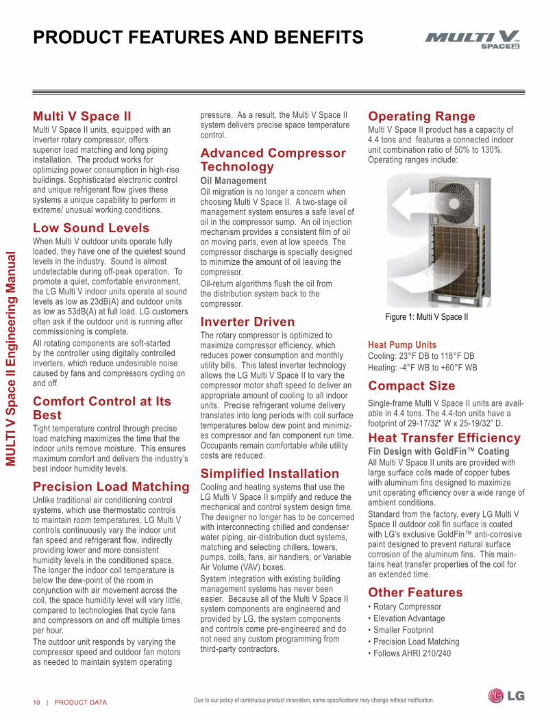
Multi V Space iiMulti V Space II units, equipped with an inverter rotary compressor, offers superior load matching and long piping installation. The product works for optimizing power consumption in high-rise buildings. Sophisticated electronic control and unique refrigerant flow gives these systems a unique capability to perform in extreme/ unusual working conditions.
low Sound levelsWhen Multi V outdoor units operate fully loaded, they have one of the quietest sound levels in the industry. Sound is almost undetectable during off-peak operation. To promote a quiet, comfortable environment, the LG Multi V indoor units operate at sound levels as low as 23dB(A) and outdoor units as low as 53dB(A) at full load. LG customers often ask if the outdoor unit is running after commissioning is complete. All rotating components are soft-started by the controller using digitally controlled inverters, which reduce undesirable noise caused by fans and compressors cycling on and off.
comfort control at its bestTight temperature control through precise load matching maximizes the time that the indoor units remove moisture. This ensures maximum comfort and delivers the industry’s best indoor humidity levels.
Precision load MatchingUnlike traditional air conditioning control systems, which use thermostatic controls to maintain room temperatures, LG Multi V controls continuously vary the indoor unit fan speed and refrigerant flow, indirectly providing lower and more consistent humidity levels in the conditioned space. The longer the indoor coil temperature is below the dew-point of the room in conjunction with air movement across the coil, the space humidity level will vary little, compared to technologies that cycle fans and compressors on and off multiple times per hour. The outdoor unit responds by varying the compressor speed and outdoor fan motors as needed to maintain system operating
pressure. As a result, the Multi V Space II system delivers precise space temperature control.
advanced compressor technologyOil Managementoil migration is no longer a concern when choosing Multi V Space II. A two-stage oil management system ensures a safe level of oil in the compressor sump. An oil injection mechanism provides a consistent film of oil on moving parts, even at low speeds. The compressor discharge is specially designed to minimize the amount of oil leaving the compressor. oil-return algorithms flush the oil from the distribution system back to the compressor.
inverter DrivenThe rotary compressor is optimized to maximize compressor efficiency, which reduces power consumption and monthly utility bills. This latest inverter technology allows the LG Multi V Space II to vary the compressor motor shaft speed to deliver an appropriate amount of cooling to all indoor units. Precise refrigerant volume delivery translates into long periods with coil surface temperatures below dew point and minimiz-es compressor and fan component run time. occupants remain comfortable while utility costs are reduced.
Simplified installationCooling and heating systems that use the LG Multi V Space II simplify and reduce the mechanical and control system design time. The designer no longer has to be concerned with interconnecting chilled and condenser water piping, air-distribution duct systems, matching and selecting chillers, towers, pumps, coils, fans, air handlers, or Variable Air Volume (VAV) boxes.System integration with existing building management systems has never been easier. Because all of the Multi V Space II system components are engineered and provided by LG, the system components and controls come pre-engineered and do not need any custom programming from third-party contractors.
operating rangeMulti V Space II product has a capacity of 4.4 tons and features a connected indoor unit combination ratio of 50% to 130%. operating ranges include:
Heat Pump UnitsCooling: 23°F DB to 118°F DBHeating: -4°F WB to +60°F WB
compact SizeSingle-frame Multi V Space II units are avail-able in 4.4 tons. The 4.4-ton units have a footprint of 29-17/32" W x 25-19/32” D. heat transfer EfficiencyFin Design with GoldFin™ CoatingAll Multi V Space II units are provided with large surface coils made of copper tubes with aluminum fins designed to maximize unit operating efficiency over a wide range of ambient conditions. Standard from the factory, every LG Multi V Space II outdoor coil fin surface is coated with LG’s exclusive GoldFin™ anti-corrosive paint designed to prevent natural surface corrosion of the aluminum fins. This main-tains heat transfer properties of the coil for an extended time.
other Features•Rotary Compressor•Elevation Advantage•Smaller Footprint•Precision Load Matching•Follows AHRI 210/240
Figure 1: Multi V Space II
ProDuct FEaturES anD bEnEFitS

PROdUcT dATA | 11
Product Data
Due to our policy of continuous product innovation, some specifications may change without notification.
outdoor units (oDu)
aru n 053 g F 2
Generation2 = Second
Airflow ConfigurationF = Front Discharge
Electrical RatingsG = 208–230V/60Hz/1Ph
nominal Capacity (nominal cooling capacity in Btu/h)053 = 53,000
Typen = Inverter Heat Pump
FamilyARU = Multi V outdoor Unit (Refrigerant R410A)
unit noMEnclaturEOutdoor Unit
12 | PROdUcT dATA
MUL
TI V
Spa
ce II
Eng
inee
ring
Man
ual
Due to our policy of continuous product innovation, some specifications may change without notification.
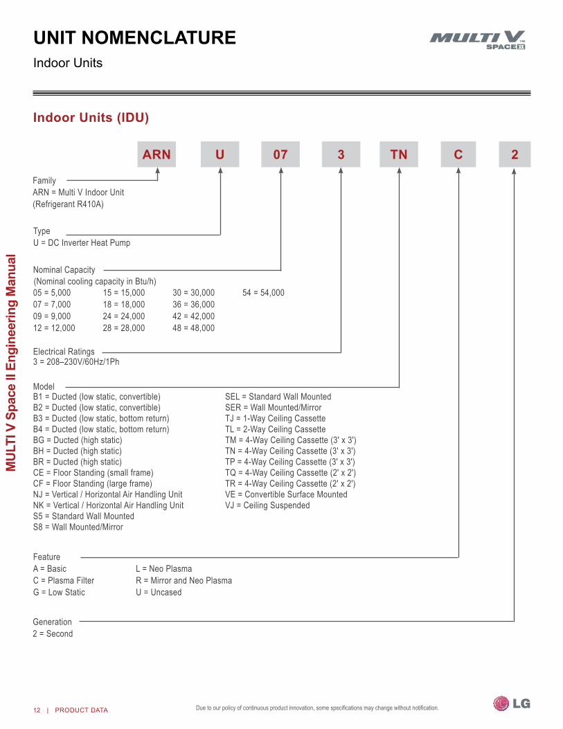
indoor units (iDu)
arn u 07 3 tn c
Generation2 = Second
Electrical Ratings 3 = 208–230V/60Hz/1Ph
05 = 5,00007 = 7,00009 = 9,00012 = 12,000
15 = 15,00018 = 18,00024 = 24,00028 = 28,000
30 = 30,00036 = 36,00042 = 42,00048 = 48,000
54 = 54,000
TypeU = DC Inverter Heat Pump
FamilyARn = Multi V Indoor Unit(Refrigerant R410A)
2
B1 = Ducted (low static, convertible) B2 = Ducted (low static, convertible)B3 = Ducted (low static, bottom return)B4 = Ducted (low static, bottom return)BG = Ducted (high static)BH = Ducted (high static)BR = Ducted (high static)CE = Floor Standing (small frame)CF = Floor Standing (large frame)nJ = Vertical / Horizontal Air Handling UnitnK = Vertical / Horizontal Air Handling UnitS5 = Standard Wall MountedS8 = Wall Mounted/Mirror
SEL = Standard Wall MountedSER = Wall Mounted/MirrorTJ = 1-Way Ceiling CassetteTL = 2-Way Ceiling CassetteTM=4-WayCeilingCassette(3′x3′)TN=4-WayCeilingCassette(3′x3′)TP=4-WayCeilingCassette(3′x3′)TQ=4-WayCeilingCassette(2′x2′)TR=4-WayCeilingCassette(2′x2′)VE = Convertible Surface MountedVJ = Ceiling Suspended
FeatureA = BasicC = Plasma Filter G = Low Static
L = neo PlasmaR = Mirror and neo PlasmaU = Uncased
nominal Capacity
Model
Indoor Units
unit noMEnclaturE
(nominal cooling capacity in Btu/h)

PROdUcT dATA | 13
Product Data
Due to our policy of continuous product innovation, some specifications may change without notification.
gEnEral DataARUN053GF2 Heat Pump Outdoor Unit Specification
Combination Unit Model number 4.4 Ton ARUn053GF2
Cooling Performancenominal Cooling Capacity (Btu/h)1 53,000Rated Cooling Capacity (Btu/h)2 54,000
Heating Performancenominal Heating Capacity (Btu/h)1 59,000Rated Heating Capacity (Btu/h)2 60,000
Operating RangeCooling (°F DB) 23 - 118Heating (°F WB) (-4) - +60
CompressorInverter Quantity DC Inverter Rotaryoil/Type PVE/FVC68D
Fan (Rear Discharge)Type Propeller (BLDC)Motor output (kW) x Qty. 0.90 x 1
Motor/Drive Brushless Digitally Controlled/Direct
operating Range(RPM)
Cooling 80-813Heating 80-813
Maximum Air Volume (CFM) 3,532External Static Pressure (ESP) (in. WG) 0.12 - 0.20
Unit DataRefrigerant Type R410ARefrigerant Control/Location EEV/Indoor UnitMax. number Indoor Units/System3 9Sound Pressure dB(A) (Rear Fan Side/Front Side)4 68.3/52.7net Unit Weight (lbs.) 320Shipping Weight (lbs.) 346Communication Cables5,6 2 x 18
Heat ExchangerMaterial and Fin Coating Copper Tube/Aluminum Fin and GoldFin™Rows/Fins per inch 2/14
Piping7
Liquid Line Connection (in., oD) 3/8 BrazeVapor Line Connection (in., oD) 3/4 BrazeFactory Charge lbs. of R410A 7.7
Table 1: Single-Frame 208-230V Heat Pump Unit.
1nominal capacity applied with non-ducted indoor units, and is rated 0 ft. above sea level with 25 ft. of refrigerant line per indoor unit and a 0 ft. level difference between outdoor and indoor units. All capacities are net with a Combination Ratio between 95–105%. (nominal capacity is outside the scope of AHRI Standard 210/240.) nominal cooling capacity rating obtained with air entering the indoor unit at 80ºF dry bulb (DB) and 67ºF wet bulb (WB) and outdoor ambient conditions of 95ºF dry bulb (DB) and 75ºF wet bulb (WB). nominal heating capacity rating obtained with air entering the indoor unit at 70ºF dry bulb (DB) and 59ºF wet bulb (WB) and outdoor ambient conditions of 47ºF dry bulb (DB) and 43ºF wet bulb (WB).2Rated capacity is certified under AHRI Standard 210/240. See www.ahrinet.org for information.3The System Combination Ratio must be between 50–130%.
4Sound pressure levels are tested in an anechoic chamber under ISo Standard 37455All communication cable to be minimum 18 AWG, 2-conductor, stranded, shielded, and must comply with applicable local and national codes.6Power wiring cable is field provided and must comply with the applicable local and national codes. See page 14 for detailed electrical data.7Refer to the Refrigerant Piping section of this manual for correct line sizing. Contractor must use LG manufactured Y-Branch and Header Kits only. Designer must verify refrigerant piping design configura-tion using LG’s computerized refrigerant piping (LATS Multi V) software to validate the pipe design.

14 | PROdUcT dATA
MUL
TI V
Spa
ce II
Eng
inee
ring
Man
ual
Due to our policy of continuous product innovation, some specifications may change without notification.
nom. Tons Unit Model no. Compressor Qty Compressor
Motor (A) Fan Qty Condenser Fan Motor (A) MCA MoP
4.4 ARUn053GF2 1 21.7 1 4.0 31.2 50
ARUn053GF2 Heat Pump Outdoor Unit
ElEctrical Data
Table 2: Multi V Space II Electrical Data
Voltage tolerance is ±10%.Maximum allowable voltage unbalance is 2%.MCA = Minimum Circuit Ampacity.
Maximum overcurrent Protectin (MoP) is calculated as follows: (Largest motor FLA x 2.25) + (Sum of other motor FLA) rounded down to the nearest standard fuse size.

PROdUcT dATA | 15
Product Data
Due to our policy of continuous product innovation, some specifications may change without notification.
Wall Mounted–ART CooLTM
Mirror073 SER2 7,500 8,500093 SER2 9,600 10,900123 SER2 12,300 13,600153 SER2 15,400 17,100183 S8R2 19,100 21,500243 S8R2 24,200 27,300
Wall Mounted–Standard Finish 073 SEL2 7,500 8,500093 SEL2 9,600 10,900123 SEL2 12,300 13,600153 SEL2 15,400 17,100183 S5L2 19,100 21,500243 S5L2 24,200 27,300
Ceiling Cassette–1 Way 073 TJC2 7,500 8,500
093 TJC2 9,600 10,900
123 TJC2 12,300 13,600
Ceiling Cassette–2 Way183 TLC2 19,100 21,500
243 TLC2 24,200 27,300
Ceiling Cassette–4 Way (2' x 2') 053 TRC2 5,500 6,100073 TRC2 7,500 8,500093 TRC2 9,600 10,900123 TRC2 12,300 13,600153 TQC2 15,400 17,100183 TQC2 19,100 21,500
CeilingCassette–4Way(3′x3′) 093 TPAA 9,600 10,900123 TPAA 12,300 13,600153 TPAA 15,400 17,100183 TnAA 19,100 21,500243 TnAA 24,200 27,300243 TPC2 24,200 27,300283 TPC2 28,000 31,500363 TnC2 36,200 40,600423 TMC2 42,000 43,800483 TMC2 48,100 51,200
Indoor Unit Specifications
gEnEral Data
Unit / Type1 ARnU*****2nominal Capacity Btu/h
Cooling3 Heating3
1All indoor units require 208–230V/60Hz/1Ph and an AWG18-2 communication cable. Reference LG’s Multi V Indoor Unit Engineering Manual for complete detailed engineering data and selection procedures.2Model number shows nominal capacity and frame size designator.
3nominal cooling capacity rating obtained with air entering the indoor unit at 80ºF dry bulb (DB) and 67ºF
wet bulb (WB) and outdoor ambient conditions of 95ºF dry bulb (DB) and 75ºF wet bulb (WB). nominal heating capacity rating obtained with air entering the indoor unit at 70ºF dry bulb (DB) and 59ºF wet bulb (WB) and outdoor ambient conditions of 47ºF dry bulb (DB) and 43ºF wet bulb (WB).
Table 3: Summary Data—Wall-Mounted / Ceiling Cassette Indoor Units.

16 | PROdUcT dATA
MUL
TI V
Spa
ce II
Eng
inee
ring
Man
ual
Due to our policy of continuous product innovation, some specifications may change without notification.
Table 4: Summary Data—Recessed Mounted Indoor Units.
gEnEral DataIndoor Unit Specifications
Unit / Type1 ARnU***2nominal Capacity Btu/h
Cooling3 Heating3
Ducted High Static 073 BHA2 7,500 8,500093 BHA2 9,600 10,900123 BHA2 12,300 13,600153 BHA2 15,400 17,100183 BHA2 19,100 21,500243 BHA2 24,200 27,300153 BGA2 15,400 17,100183 BGA2 19,100 21,500243 BGA2 24,200 27,300283 BGA2 28,000 31,500363 BGA2 36,200 40,600423 BGA2 42,000 43,800483 BRA2 48,100 51,200543 BRA2 54,000 61,400
Ducted Low Static–Convertible 073 B1G2 7,500 8,500093 B1G2 9,600 10,900123 B1G2 12,300 13,600153 B1G2 15,400 17,100183 B2G2 19,100 21,500243 B2G2 24,200 27,300
Ducted Low Static–Bottom Return 073 B3G2 7,500 8,500093 B3G2 9,600 10,900123 B3G2 12,300 13,600153 B3G2 15,400 17,100183 B4G2 19,100 21,500243 B4G2 24,200 27,300
Vertical / Horizontal Air HandlingUnit 123 nJ2 12,000 13,500
183 nJA2 18,000 20,000
243 nJA2 24,000 27,000
303 nJA2 30,000 34,000
363 nJA2 36,000 40,000
423 nKA2 42,000 46,000
483 nKA2 48,000 54,000
543 nKA2 54,000 60,0001All indoor units require 208–230V/60Hz/1Ph and an AWG18-2 communication cable. Reference LG’s Multi V Indoor Unit Engineering Manual for complete detailed engineering data and selection procedures.2Model number shows nominal capacity and frame size designator.
3 nominal cooling capacity rating obtained with air entering the indoor unit at 80ºF dry bulb (DB) and 67ºF wet bulb (WB) and outdoor ambient conditions of 95ºF dry bulb (DB) and 75ºF wet bulb (WB). nominal heating capacity rating obtained with air entering the indoor unit at 70ºF dry bulb (DB) and 59ºF wet bulb (WB) and outdoor ambient conditions of 47ºF dry bulb (DB) and 43ºF wet bulb (WB).

PROdUcT dATA | 17
Product Data
Due to our policy of continuous product innovation, some specifications may change without notification.
Table 5: Summary Data—Surface Mounted / Floor Standing Indoor Units.
Indoor Unit Specifications
gEnEral Data
Unit / Type1 ARnU****2nominal Capacity Btu/h
Cooling3 Heating3
Ceiling Suspended183VJA2 19,100 21,500
243VJA2 24,200 27,300
Convertible Surface Mounted093VEA2 9,600 10,900
123VEA2 12,300 13,600
Floor Standing–with Case073 CEA2 7,500 8,500
093 CEA2 9,600 10,900
123 CEA2 12,300 13,600
153 CEA2 15,400 17,100
183 CFA2 19,100 21,500
243 CFA2 24,200 27,300
Floor Standing–without case073 CEU2 7,500 8,500
093 CEU2 9,600 10,900
123 CEU2 12,300 13,600
153 CEU2 15,400 17,100
183 CFU2 19,100 21,500
243 CFU2 24,200 27,300
1All indoor units require 208–230V/60Hz/1Ph and an AWG18-2 communication cable. Reference LG’s Multi V Indoor Unit Engineering Manual for complete detailed engineering data and selection procedures.2Model # shows nominal capacity and frame size designator.
3nominal cooling capacity rating obtained with air entering the indoor unit at 80ºF dry bulb (DB) and 67ºF wet bulb (WB) and outdoor ambient conditions of 95ºF dry bulb (DB) and 75ºF wet bulb (WB). nominal heating capacity rating obtained with air entering the indoor unit at 70ºF dry bulb (DB) and 59ºF wet bulb (WB) and outdoor ambient conditions of 47ºF dry bulb (DB) and 43ºF wet bulb (WB).

18 | PROdUcT dATA
MUL
TI V
Spa
ce II
Eng
inee
ring
Man
ual
Due to our policy of continuous product innovation, some specifications may change without notification.
Indoor Unit controls and Options
gEnEral Data
Table 6: Indoor Units—Controls and options.
Indoor Unit Type
Wall
Mou
nted—
St
anda
rd F
inish
Wall
Mou
nted—
AR
T Co
oL™
Mi
rror
1-W
ay C
asse
tte
2-W
ay C
asse
tte
4-W
ay C
asse
tte
Ducte
d High
St
atic
Ducte
d Low
St
atic-
Conv
ertib
leDu
cted L
ow
Stati
c—Bo
ttom
Retur
nVe
rt.-H
oriz.
AH
U (n
J)Ve
rt.-H
oriz.
AH
U (n
K)
Ceilin
g Su
spen
ded
Conv
ertib
le
Surfa
ce M
ount
Floor
Mou
nt—Ca
sed
Floor
Mou
nt—Un
case
d
nominal Chassis Size (MBH) 7–24 7–24 7–12 18–24 5–18 24–48 7–54 7–24 7–24 1–3 3.5–4.5 18–24 9–12 7–24 7–24
Airflo
w
Air supply outlets 1 1 1 2 4 4 1 1 1 1 1 1 1 1 1Airflow direction (left/right) manual /
auto auto manual manualAuto airflow direction (up/down) √ √ √ √ √ √ √ √Fan speed (Heating mode) (qty.) (3) (3) (4) (4) (4) (4) (3) (3) (3) (3) (3) (3) (3) (3) (3)Fan speed (Cooling mode) (qty.) (4) (4) (5) (5) (5) (5) (3) (3) (3) (3) (3) (4) (4) (3) (3)Fan speed (Fan mode) (qty.) (3) (3) (4) (4) (4) (4) (3) (3) (3) (3) (3) (3) (3) (3) (3)Chaos swing (random louver swing) √ √Chaos wind (random fan speed) √ √ √ √ √ √ √ √Jet-cool (power cooling) √ √ √ √ √ √ √ √
oper
ation
E.S.P. control √ √ √ √ √ √ √ √ √ √ √High ceiling √ √ √ √ √ √Auto-restart after power restore √ √ √ √ √ √ √ √ √ √ √ √ √ √ √Hot Start √ √ √ √ √ √ √ √ √ √ √ √ √ √ √Diagnostics √ √ √ √ √ √ √ √ √ √ √ √ √ √ √Soft Dry (dehumidification) √ √ √ √ √ √ √ √ √ √ √ √ √ √ √Auto changeover (HR) √ √ √ √ √ √ √ √ √ √ √ √ √ √ √Auto clean (coil dry) √ √Child lock √ √ √ √ √ √ √ √ √ √ √ √ √ √ √Forced operation √ √ √ √ √ √ √ √Group control – Requires theuse of one Group control CableKit (PZCWRCG3) for everyadditional indoor unit
√ √ √ √ √ √ √ √ √ √ √ √ √ √ √
Sleep mode √ √ √ √ √ √ √ √ √ √ √ √ √ √ √Timer (on/off) √ √ √ √ √ √ √ √ √ √ √ √ √ √ √Weekly schedule √ √ √ √ √ √ √ √ √ √ √ √ √ √ √Two thermistor control √ √ √ √ √ √ √ √ √ √ √ √ √ √ √Test operation mode √ √ √ √ √ √ √ √ √ √ √ √ √ √ √
Filter Plasma2 √ √ √ √5 √5 √5
Washable anti-fungal1 √ √ √ √ √ √ √ √ √ √ √ √ √
Contr
oller
s LG Programmable Thermostat o o o o o o o o o o o o o o oSimple controller w/mode o o o o o o o o o o o o o o oSimple controller w/o mode o o o o o o o o o o o o o o oWireless hand held controller o o o o o o o3 o3 o3 o o o3 o3
othe
rs
Condensate lift √ √ √ √ √ √ √Ventilation air √ √4 √4 √ √ √Casing √ √ √ √ √ √ √ √ √Standard grille √ √ √ √Auto elevation grille √5
Color Panels (qty.) (3)Suction grille oSuction canvas oAux. Heat Kit √ √
1Primary washable filters.2Secondary plasma filters. not available with ARnU093-153TPAA, ARnU183-243TnAA.3Requires LG Programmable Thermostat.
4Requires ventilation kit PTVK430 (For TR, TQ frames) or PTVK410+PTVK420 (For TP, Tn, TM frames)(Temperature, humidity, and volume limitations apply).5Requires standard grille.
√=Standardfeatureo = Unit option

PROdUcT dATA | 19
Product Data
Due to our policy of continuous product innovation, some specifications may change without notification.
ARUn053GF2
outDoor unit DiMEnSionS
Top View
Front View
Bottom View
Side View Rear View
WX
DL1
Y
L6
L7
M4M1 M2 M3
H
ZL3
L2
L4 L5X 14-5/8"Y 11-3/8"Z 31-1/2"
W 29-1/2"D 25-1/2"H 70-1/2"L1 1-1/4"L2 6"L3 1-13/16"L4 11-13/16"L5 2-13/16"L6 26-3/8"L7 23-15/16"M1 2-5/8"M2 20-5/16"M3 2-9/16"M4 28-1/2"
Center of Gravity
Dimensions

20 | PROdUcT dATA
MUL
TI V
Spa
ce II
Eng
inee
ring
Man
ual
Due to our policy of continuous product innovation, some specifications may change without notification.
SounD PrESSurE lEVElS
Multi V Space II ModeldB(A)
208-230V
ARUn053GF2Front: 52.7Rear: 68.3
•Measurementtaken3.3′abovefinishedfloor,andatadistanceof3.3′fromfaceofunit.•Measurements taken with no attenuation and units operating at full load normal operat-
ing condition.•Sound level will vary depending on a range of factors such as construction (acoustic
absorption coefficient) of particular area in which the equipment is installed.•Sound level may be increased in static pressure mode or if air guide is used.•Sound power levels are measured in dB(A)±3.•Tested in anechoic chamber per ISo Standard 3745.
ARUn053GF2
Sound Pressure Level - Fan Side (Rear)
Sound Pressure Level - Panel Side (Front)
3.3ft
Microphone
3.3ft
Multi V Space ii acoustical Data
Figure 3: Multi V Space II Acoustics - Fan Side (Rear)
Figure 2: Multi V Space II Acoustics - Panel Side (Front)
3.3ft
Microphone
3.3ft
PROdUcT dATA | 21
Product Data
Due to our policy of continuous product innovation, some specifications may change without notification.
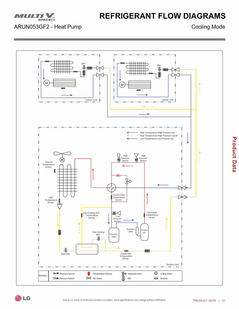
rEFrigErant FloW DiagraMScooling ModeARUn053GF2 - Heat Pump
s sPressure Sensor
Pressure Switch
Temperature Sensor
SVC Valve
Solenoid valve
EEV
4-Way Valve
StrainerRemarks
S
M
Main EEV
Inlet AirTemperature
Sensor
HEXTemperature
Sensor
Sub-Cooling OUT Temperature
Sensor
Liquid PipeTemperature
Sensor
DischargeTemperature
Sensor
Suction-PipeTemperature
Sensor
HighPressureSensor
HighPressure
Switch
LowPressureSensor
M
EEV
M
EEV
Sub-CoolingEEV Accumu
lator
Accumulator
Compressor
High Temperature High Pressure Gas High Temperature High Pressure Liquid Low Temperature Low Pressure Gas
Outdoor Unit
tinU roodnI tinU roodnI

22 | PROdUcT dATA
MUL
TI V
Spa
ce II
Eng
inee
ring
Man
ual
Due to our policy of continuous product innovation, some specifications may change without notification.
Heating Mode
rEFrigErant FloW DiagraMSARUn053GF2 - Heat Pump
S
M
Main EEV
Inlet AirTemperature
Sensor
HEXTemperature
Sensor
Sub-Cooling OUTTemperature
Sensor
DischargeTemperature
Sensor
Liquid PipeTemperature
Sensor
Suction-PipeTemperature
Sensor
HighPressure
Switch
HighPressureSensor
LowPressureSensor
Sub-CoolingEEV Accumu
lator
Accumulator
Compressor
M
EEV
M
EEV
High Temperature High Pressure Gas High Temperature High Pressure Liquid Low Temperature Low Pressure Gas
Outdoor Unit
Indoor Unit Indoor Unit
s sPressure Sensor
Pressure Switch
Temperature Sensor
SVC Valve
Solenoid valve
EEV
4-Way Valve
StrainerRemarks
PROdUcT dATA | 23
Product Data
Due to our policy of continuous product innovation, some specifications may change without notification.
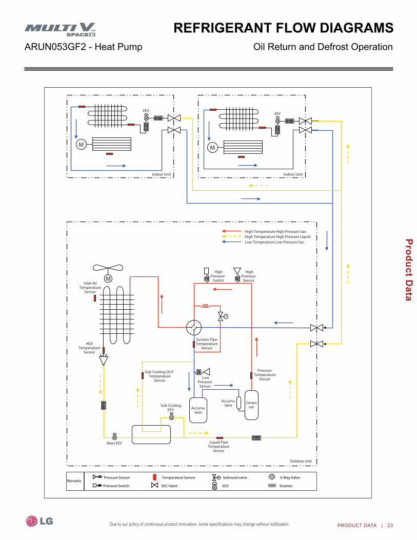
Oil Return and defrost Operation
rEFrigErant FloW DiagraMSARUn053GF2 - Heat Pump
S
M
Main EEV
Inlet AirTemperature
Sensor
HEXTemperature
Sensor
Sub-Cooling OUTTemperature
Sensor
PressureTemperature
Sensor
Liquid PipeTemperature
Sensor
Suction-PipeTemperature
Sensor
HighPressure
Switch
HighPressureSensor
LowPressureSensor
Sub-CoolingEEV Accumu
lator
Accumulator
Compressor
M
EEV
M
EEV
High Temperature High Pressure Gas High Temperature High Pressure Liquid Low Temperature Low Pressure Gas
Outdoor Unit
Indoor Unit Indoor Unit
s sPressure Sensor
Pressure Switch
Temperature Sensor
SVC Valve
Solenoid valve
EEV
4-Way Valve
StrainerRemarks

24 | PROdUcT dATA
MUL
TI V
Spa
ce II
Eng
inee
ring
Man
ual
Due to our policy of continuous product innovation, some specifications may change without notification.
Wiring DiagraM

PROdUcT dATA | 25
Product Data
Due to our policy of continuous product innovation, some specifications may change without notification.
Table 7: Summary Data - Zone Controllers
Zone Controller name Model no. Case Color
Max. Wire Length (ft.) Description
Simple Controller with Mode Selection
PQRCVCL0Q Black
164Allows control of indoor unit on / oFF, operation mode, fan speed, and temperaturesetpoint for up to 16 indoor units.
PQRCVCL0QW White
Simple Controller without Mode Selection
PQRCHCA0Q Black
164Allows control of indoor unit on / oFF, fan speed, and temperature setpoint for up to 16 indoor units.
PQRCHCA0QW White
LG ProgrammableThermostat PREMTB10U White 164
Allows control of indoor unit on / oFF, operationmode, occupied / unoccupied temperature setpoints, fan speed, and airflow direction for upto 16 indoor units. Programmable schedule withfive events per day.
Wireless Handheld PQWRHDF0 Ivory —Allows control of indoor unit on / oFF, operation mode, fan speed, and temperaturesetpoint. Also provides subfunction control.
Wall-Mounted Remote Temperature Sensor PQRSTA0 Ivory 50 Allows remote temperature measurement for
cassette and ducted indoor units.
Before specifying or placing an order, refer to the V-net network Solutions Engineering Product Data Book, and review the detailed technical data provided to fully understand the capabilities and limitations of these devices.For information, refer to the Controls and options Table on page 18.
Table 8: Summary Data - Zone Controller Communication Cables
Before specifying or placing an order, refer to the V-net network Solutions Engineering Product Data Book, and review the detailed technical data provided to fully understand the capabilities and limitations of these devices.For information, refer to the Controls and options Table on page 18.
Communication Cable name Model no. Max. Wire Length (ft.) Description
Wired Remote Group Control Cable Assembly PZCWRCG3 32 Required when grouping multiple indoor units with a
single zone controller.
Wired Remote / Group ControlExtension Cable PZCWRC1 32
Increases the distance between a remote controller and an indoor unit, or between indoor units in a control group.
accESSoriES

26 | PROdUcT dATA
MUL
TI V
Spa
ce II
Eng
inee
ring
Man
ual
Due to our policy of continuous product innovation, some specifications may change without notification.
Table 9: Summary Data—Specialty Application DevicesSpecialty Application
Device name Model no. Connects To Application Binary Signals
Input / output Description
Dry Contact Unit24 VAC PQDSB1
Indoor Unit
on / oFF, Run Status,Error Status 1 / 2
Enables the indoor unit to becontrolled and monitored by third-party controls using binary inputs and outputs.Dry Contact Unit
for Setback PQDSBC
on / oFF, Mode, Controller Lock, Power Save, Run Status, Error Status
2 / 2
Dry Contact Unitfor Thermostat PQDSBnGCM1
on / oFF, Thermoon / oFF, Mode, FanSpeed, Run Status,Error Status
—
Enables the indoor unit to be controlled and monitored by athird-party thermostat or controller.
Digital output(Do) Kit PQnFP00T0 Comm. BUS on / oFF 0 / 1
one 25A DPST normally openrelay. Used with central controller to control third-partydevice manually or by schedule.
Auxiliary HeaterRelay Kit
PRARH0
Indoor UnitThird-party Supplemental Heat Control
0 /1
Adds coordinated control ofan external heater with normalheat pump operations. Contact energizes at 2.7°F below setpoint. De-energizesat 2.7°F above setpoint.
PRARS0
Power DistributionIndicator (PDI)
PremiumPQnUD1S41 Comm. BUS Energy Consumption
Monitoring 8 / 0
Monitors total water source unitpower consumption for up to eight systems, and distributesper indoor unit based on weighted calculation.
Mode SelectorSwitch PRDSBM outdoor
UnitMulti V Heat Pumpsonly — Locks outdoor unit into Heat,
Cool, or Fan mode.
Before specifying or placing an order, refer to the V-net network Solutions Engineering Product Data Book, and review the detailed technical data provided to fully understand the capabilities and limitations of these devices.For information, refer to the Controls and options Table on page 18.
accESSoriES

PROdUcT dATA | 27
Product Data
Due to our policy of continuous product innovation, some specifications may change without notification.
Table 10: Summary Data—Central Controllers (Connect to the outdoor Unit Terminals Internet A, Internet B)
Central Controller name Model no.Devices
perController
Systems per
Comm. BUS
Devices per Comm.
BUS
no. of Comm.
BUS ports
Binary Signals Input / output
Power /Connection Description
AC SmartPremium PQCSW421E0A 128 16 128 1 2 DI /
2 Do 24 VAC
Provides for scheduling, auto-changeover, setback,remote controller lock, setpoint range limit, runtime limit, web access, email alarm notification,visual floorplan navigation,peak/demand control, software device interlocking,PDI integration, and AC Manager Plus integration advanced functionality in addition to basic unit controland monitoring.
AC Ez PQCSZ250S0 32 16 256 1 —12 VDC /outdoor
Unit
Provides for scheduling in addition to basic indoor unit control and monitoring.
Advanced Control Platform (ACP)
StandardPQCPC22n1 256 16
64 (128with PDI
Premium)4
2 / 2 24 VAC
Provides for scheduling, remote controller lock, setpointrange limit, web access, peak / demand control, PDI integration, and AC Manager Plus integration advanced functionality in addition to basic unit control and monitoring.
Advanced Control Platform (ACP)
PremiumPQCPC22A1 256 16
64 (128with PDI
Premium)10 / 4 24 VAC
Table 11: Summary Data—Integration Solutions (Connect to outdoor Unit Terminals Internet A, Internet B).
Central Controller name Model no.Devices
perController
Systems per
Comm. BUS
Devices per Comm.
BUS
no. of Comm.
BUS ports
Binary Signals Input / output
Power /Connection Description
BACnet® Gateway PQnFB17C1 256 1664 (128with PDI
Premium)4 2 / 2 24 VAC
Allow integration of LGequipment for control and monitoring by open protocol BACnet and LonWorks buildingautomation and controlssystems.
LonWorks® Gateway PLnWKB100 64 1664 (128with PDI
Premium)1 2 / 2 24 VAC
Before specifying or placing an order, refer to the V-net network Solutions Engineering Product Data Book, and review the detailed technical data provided to fully understand the capabilities and limitations of these devices.For information, refer to the Controls and options Table on page 18.
Before specifying or placing an order, refer to the V-net network Solutions Engineering Product Data Book, and review the detailed technical data provided to fully understand the capabilities and limitations of these devices.For information, refer to the Controls and options Table on page 18
accESSoriES

28 | PROdUcT dATA
MUL
TI V
Spa
ce II
Eng
inee
ring
Man
ual
Due to our policy of continuous product innovation, some specifications may change without notification.
•Actual inverter compressor speed•Target inverter compressor speed•Actual outdoor fan speed•Target outdoor unit fan speed•Actual superheat•Target superheat •Actual subcooler circuit superheat •Target subcooler circuit superheat •Main EEV position•Subcooling EEV position•Inverter compressor current transducer
value•outdoor air temperature•Actual high pressure/saturation temperature•Actual low pressure/saturation temperature•Suction temperature•Inverter compressor discharge temperature•Constant speed compressor discharge
temperature•Front outdoor coil pipe temperature•Back outdoor coil pipe temperature•Liquid line pipe temperature•Subcooler inlet temperature•Subcooler outlet temperature
•Average indoor unit (IDU) pipe temperature
•Inverter compressor opera-tion indicator light
•Constant speed compressor operation indicator light
•Liquid injection valves’ operation indicator lights
•Hot gas bypass valve operation indicator light
•Four-way reversing valve operation indicator light
•Pressure graph showing actual low pressure and actual high pressure levels
•Error code display•operating mode indicator•Target high pressure•Target low pressure•PCB (printed circuit board) version•Software version•Installer name•Model number of outdoor units•Site name•Total number of connected indoor units
•Communication indicator lights•Indoor unit capacity•Indoor unit operating mode•Indoor unit fan speed•Indoor unit EEV position•Indoor unit room temperature•Indoor unit inlet pipe temperature•Indoor unit outlet pipe temperature•Indoor unit error code
lg Monitoring (lgMV) Diagnostic Software and cable(PRCTSL1 and PRCTFE1)LGMV software allows the service technician or commissioning agent to connect a computer USB port to the outdoor unit main printed circuit board (PCB) using an accessory cable without the need for a separate interface device. The main screen for LGMV shall allow user to view the following real time data on one screen:
accESSoriES
Additional screens can be accessed by tabs on the main screen: 1. Cycleview: Graphic of internal components including:
•Compressors showing actual speeds•EEVs•IDUs•Liquid injection valves
•Temperature and pressure sensors•Four-way reversing valve•outdoor fans showing status and speeds
2. Graph: Full screen graph of actual high and low pressures and high and low pressure limits. A sliding bar enables user to go back in time and view data.
3. Control IDU: Enables user to turn on all IDU’s default setpoints of 86°F in heat mode or 64°F in cool mode.
4. Setting: Converts metric values to imperial values.5. Making Data: Recording of real time data to a separate file created to be stored on the user’s computer.6. Loading Data: Recorded data from a saved “.CSV” file can be loaded to create an LGMV session.7. Electrical Data: The lower half of main screen is changed to show the following:
Figure 4: MV Real-time Data Screen.
•Inverter compressor- Amps- Volts- Power Hz
- Inverter control board fan Hz•Constant compressor
- Current transducer value- Phase
Figure 5: MV Cycleview

PROdUcT dATA | 29
Product Data
Due to our policy of continuous product innovation, some specifications may change without notification.
accESSoriES
The software is available in a high version with all of the features listed above. The low version has all features as the high version without Target High Pressure and Target Low Pressure values shown on main screen. In lieu of connecting to the oDU, user has the option to connect to IDU with the use of a USB to RS-485 connector kit. When connected through IDU, user will not be able to record data.This software can be used to both commission new systems and troubleshoot existing systems. LGMV data can be recorded to a
“.CSV” file and emailed to an LG representative to assist with diag-nostic evaluations.
Recommended Minimum PC Configuration:
•CPU: Pentium® IV 1.6 GHz•operating System: Windows®
nT/2000/XP/Vista•Main Memory: 256 MB
•Hard Disk: 600 MB when operating
•Web Browser: Internet Explorer® 5.0
LG Monitoring View (LGMV) Diagnostic Software and Cable - Continued
30 | PROdUcT dATA
MUL
TI V
Spa
ce II
Eng
inee
ring
Man
ual
Due to our policy of continuous product innovation, some specifications may change without notification.
This page intentionally left blank.

“cooling capacity Data” on page 32“heating capacity Data” on page 35
PERFoRMAnCE DATA

32 | PROdUcT dATA
MUL
TI V
Spa
ce II
Eng
inee
ring
Man
ual
Due to our policy of continuous product innovation, some specifications may change without notification.
cooling capacity
PErForMancE Data
Combination (%)
outdoor air temp. (°F DB)
Indoor Air Temp. °F DB/°F WB68/57 73/61 79/64 80/67 85/70 88/73 91/76
TC PI TC PI TC PI TC PI TC PI TC PI TC PIMBh kW MBh kW MBh kW MBh kW MBh kW MBh kW MBh kW
130
23 49.1 2.03 58.3 2.46 67.8 2.91 70.3 3.15 71.3 3.38 73.8 3.88 75.5 4.0125 49.1 2.04 58.3 2.47 67.8 2.93 70.3 3.16 71.3 3.41 73.8 3.90 75.5 4.0430 49.1 2.07 58.3 2.51 67.8 2.96 70.3 3.20 71.3 3.44 73.8 3.95 75.5 4.0935 49.1 2.09 58.3 2.54 67.8 3.00 70.3 3.24 71.3 3.49 73.8 3.99 75.5 4.1340 49.1 2.12 58.3 2.57 67.8 3.03 70.3 3.28 71.3 3.53 73.8 4.04 75.5 4.1845 49.1 2.14 58.3 2.59 67.8 3.07 70.3 3.31 71.3 3.56 73.8 4.09 75.5 4.2350 49.1 2.16 58.3 2.62 67.8 3.10 70.3 3.35 71.3 3.60 73.8 4.13 75.5 4.2755 49.1 2.20 58.3 2.67 67.8 3.16 69.3 3.42 70.3 3.67 72.8 4.20 74.5 4.3060 49.1 2.27 58.3 2.76 66.8 3.29 67.8 3.55 68.5 3.81 71.0 4.33 72.8 4.3565 49.1 2.32 58.3 2.82 65.8 3.35 66.8 3.62 67.6 3.89 70.0 4.47 71.8 4.5170 49.1 2.23 58.3 2.71 64.6 3.34 65.3 3.67 66.3 4.03 68.7 4.48 70.5 4.5275 49.1 2.29 58.3 2.89 63.6 3.57 64.3 3.94 65.3 4.32 67.7 4.69 69.5 4.7280 49.1 2.60 58.3 3.29 61.8 4.08 62.6 4.51 63.6 4.95 66.0 5.09 67.7 5.1385 49.1 2.77 58.3 3.52 60.8 4.36 61.8 4.81 62.6 5.26 65.0 5.30 66.7 5.3590 49.1 3.14 57.3 4.00 59.1 4.95 59.8 5.48 60.8 5.67 63.2 5.71 65.0 5.7795 49.6 3.33 56.9 4.25 58.7 5.29 59.7 5.85 60.5 5.87 62.8 5.93 64.6 5.98100 49.6 3.60 55.9 4.60 57.7 5.73 58.7 6.15 59.5 6.19 62.1 6.25 63.9 6.30105 49.6 4.06 54.4 5.20 56.2 6.47 57.0 6.62 57.9 6.65 59.9 6.71 60.8 6.78110 49.6 4.56 52.2 5.86 54.4 7.05 54.5 7.09 55.3 7.11 56.5 7.18 56.7 7.25115 49.4 5.27 50.3 6.74 50.3 7.44 50.3 7.44 50.3 7.44 51.0 7.45 51.2 7.46118 42.9 4.47 43.7 5.71 43.8 6.25 43.8 6.31 43.8 6.31 44.4 6.32 44.2 6.33*122 34.3 3.39 35.1 4.34 34.9 4.76 35.0 4.77 35.1 4.78 35.7 4.79 35.6 4.81
120
23 44.7 1.91 53.3 2.31 62.0 2.73 66.4 2.95 69.4 3.18 72.5 3.64 74.0 3.7725 44.7 1.92 53.3 2.32 62.0 2.75 66.4 2.97 69.4 3.20 72.5 3.66 74.0 3.7930 44.7 1.94 53.3 2.35 62.0 2.78 66.4 3.01 69.4 3.23 72.5 3.71 74.0 3.8335 44.7 1.97 53.3 2.38 62.0 2.82 66.4 3.05 69.4 3.27 72.5 3.75 74.0 3.8840 44.7 1.99 53.3 2.41 62.0 2.85 66.4 3.08 69.4 3.31 72.5 3.80 74.0 3.9345 44.7 2.02 53.3 2.44 62.0 2.88 66.4 3.12 69.4 3.35 72.5 3.84 74.0 3.9850 44.7 2.04 53.3 2.47 62.0 2.92 66.4 3.15 69.4 3.39 72.5 3.88 74.0 4.0255 44.7 2.07 53.3 2.51 62.0 2.97 66.4 3.22 68.6 3.46 71.5 3.95 73.3 4.0560 44.7 2.14 53.3 2.60 62.0 3.10 65.9 3.34 66.7 3.59 69.8 4.08 71.3 4.1565 44.7 2.18 53.3 2.66 62.0 3.15 64.9 3.41 65.9 3.66 68.7 4.21 70.5 4.2470 44.7 2.14 53.3 2.60 62.0 3.20 63.7 3.52 64.4 3.87 67.5 4.30 69.0 4.3475 44.7 2.20 53.3 2.77 62.0 3.43 62.7 3.78 63.7 4.15 66.5 4.50 68.2 4.5380 44.7 2.50 53.3 3.16 60.2 3.92 61.0 4.33 61.7 4.76 64.7 4.89 66.2 4.9385 44.7 2.66 53.3 3.37 59.3 4.19 60.0 4.62 61.0 5.05 63.7 5.09 65.5 5.1390 44.7 3.01 53.3 3.84 57.5 4.76 58.3 5.26 59.0 5.44 61.9 5.49 63.5 5.5495 45.2 3.19 53.9 4.08 57.1 5.08 57.9 5.61 58.9 5.64 61.6 5.69 63.4 5.74100 45.2 3.46 53.9 4.41 56.1 5.50 57.1 5.91 57.9 5.94 60.8 6.00 62.3 6.05105 45.2 3.89 53.0 5.00 54.6 6.21 55.5 6.35 56.2 6.39 59.0 6.44 60.0 6.50110 45.2 4.37 51.7 5.63 53.4 6.77 53.5 6.81 54.3 6.83 56.0 6.90 56.2 6.96115 43.9 5.06 49.8 6.47 49.8 7.14 49.8 7.14 49.8 7.14 51.0 7.15 51.2 7.17118 39.2 4.47 43.3 5.49 43.3 6.00 43.3 6.06 43.3 6.06 44.4 6.07 44.2 6.08*122 31.3 3.39 34.7 4.17 34.6 4.57 34.6 4.58 34.7 4.59 35.7 4.60 35.6 4.62
110
23 41.4 1.75 49.4 2.12 57.4 2.51 61.4 2.71 65.4 2.92 72.0 3.34 73.5 3.4525 41.4 1.76 49.4 2.13 57.4 2.52 61.4 2.73 65.4 2.93 72.0 3.36 73.5 3.4730 41.4 1.79 49.4 2.16 57.4 2.56 61.4 2.76 65.4 2.97 72.0 3.40 73.5 3.5235 41.4 1.81 49.4 2.19 57.4 2.59 61.4 2.80 65.4 3.01 72.0 3.45 73.5 3.5740 41.4 1.84 49.4 2.22 57.4 2.63 61.4 2.84 65.4 3.05 72.0 3.50 73.5 3.6245 41.4 1.87 49.4 2.26 57.4 2.67 61.4 2.89 65.4 3.11 72.0 3.56 73.5 3.6850 41.4 1.90 49.4 2.30 57.4 2.72 61.4 2.94 65.4 3.16 72.0 3.62 73.5 3.7455 41.4 1.93 49.4 2.34 57.4 2.77 61.4 3.00 65.4 3.22 71.0 3.68 72.5 3.7760 41.4 1.99 49.4 2.42 57.4 2.88 61.4 3.11 65.4 3.34 69.2 3.80 70.7 3.8365 41.4 2.03 49.4 2.47 57.4 2.94 61.4 3.18 65.4 3.41 68.2 3.92 69.7 3.9570 41.4 2.05 49.4 2.50 57.4 3.07 61.4 3.38 64.1 3.71 66.9 4.12 68.5 4.1675 41.4 2.11 49.4 2.66 57.4 3.29 61.4 3.63 63.1 3.98 65.9 4.31 67.4 4.3580 41.0 2.39 48.9 3.03 56.8 3.76 60.0 4.15 60.7 4.56 63.5 4.68 65.0 4.7385 41.0 2.55 48.9 3.24 56.8 4.02 59.0 4.43 59.8 4.84 62.5 4.88 64.0 4.9290 41.0 2.89 48.9 3.68 56.5 4.56 57.3 5.04 58.0 5.22 60.7 5.26 62.2 5.3195 41.0 3.06 48.9 3.91 55.6 4.87 56.3 5.38 57.0 5.40 59.7 5.45 61.2 5.51100 41.0 3.31 48.9 4.23 54.8 5.28 55.6 5.67 56.3 5.70 58.9 5.75 60.4 5.80105 41.0 3.73 48.9 4.79 53.1 5.96 53.8 6.09 54.6 6.12 57.2 6.18 58.7 6.24110 41.0 4.19 48.9 5.40 51.5 6.49 51.6 6.53 52.4 6.55 54.0 6.61 54.2 6.67115 41.0 4.85 48.9 6.21 49.3 6.85 49.3 6.85 49.5 6.85 50.5 6.86 50.7 6.87118 39.6 4.42 42.5 5.26 42.9 5.76 42.9 5.81 43.1 5.81 44.0 5.82 43.8 5.83*122 31.7 3.35 34.1 4.00 34.2 4.38 34.3 4.39 34.5 4.40 35.3 4.41 35.2 4.43
TC = Total Capacity (MBh).PI = Power Input (kW) (includes compressor and outdoor fan).* 122ºF is above the operational range of 118ºF. Space has not been fully tested at this temperature. The System Combination Ratio must be between 50–130%.
nominal capacity as rated: 0 ft. above sea level with 25 ft. of refrigerant piping. 0 ft. level difference between outdoor and indoor units. nominal cooling capacity rating obtained with air entering the indoor unit at 80ºF dry bulb (DB) and 67ºF wet bulb (WB), and outdoor ambient conditions of 95ºF dry bulb (DB) and 75ºF wet bulb (WB).
54,000 Btu/h 208-230V Heat Pump ARUn053GF2

PROdUcT dATA | 33
Performance D
ata
Due to our policy of continuous product innovation, some specifications may change without notification.
PErForMancE Datacooling capacity
Combination (%)
outdoor air temp. (°F DB)
Indoor Air Temp. °F DB/°F WB68/57 73/61 79/64 80/67 85/70 88/73 91/76
TC PI TC PI TC PI TC PI TC PI TC PI TC PIMBh kW MBh kW MBh kW MBh kW MBh kW MBh kW MBh kW
100
23 36.4 1.59 43.4 1.92 50.4 2.27 54.0 2.45 59.3 2.68 66.5 3.07 70.3 3.1925 36.4 1.60 43.4 1.93 50.4 2.29 54.0 2.48 59.3 2.70 66.5 3.10 70.3 3.2230 36.4 1.64 43.4 1.98 50.4 2.34 54.0 2.53 59.3 2.77 66.5 3.17 70.3 3.3035 36.4 1.66 43.4 2.01 50.4 2.38 54.0 2.58 59.3 2.81 66.5 3.22 70.3 3.3540 36.4 1.69 43.4 2.05 50.4 2.42 54.0 2.62 59.3 2.85 66.5 3.27 70.3 3.4045 36.4 1.73 43.4 2.09 50.4 2.47 54.0 2.67 59.3 2.91 66.5 3.34 70.3 3.4750 36.4 1.76 43.4 2.13 50.4 2.52 54.0 2.73 59.3 2.97 66.5 3.41 70.3 3.5455 36.4 1.79 43.4 2.17 50.4 2.57 54.0 2.78 59.3 3.03 66.5 3.47 69.5 3.6060 36.4 1.85 43.4 2.25 50.4 2.68 54.0 2.89 59.3 3.15 66.3 3.58 67.5 3.6665 36.4 1.89 43.4 2.30 50.4 2.73 54.0 2.95 59.3 3.21 65.3 3.69 66.8 3.7770 36.4 1.95 43.4 2.37 50.4 2.91 54.0 3.20 59.3 3.57 64.1 3.96 65.3 4.0375 36.4 2.00 43.4 2.52 50.4 3.11 54.0 3.44 59.3 3.82 63.1 4.15 64.6 4.2080 36.4 2.27 43.4 2.87 50.4 3.56 54.0 3.93 59.3 4.39 61.3 4.50 62.6 4.5785 36.4 2.41 43.4 3.07 50.4 3.81 54.0 4.19 59.1 4.65 60.3 4.69 61.8 4.7690 36.4 2.73 43.4 3.48 50.4 4.32 54.0 4.78 57.1 5.02 58.6 5.06 59.8 5.1395 36.4 2.90 43.4 3.71 50.4 4.61 54.0 5.10 56.4 5.20 57.6 5.25 59.1 5.32100 36.4 3.13 43.4 4.00 50.4 4.99 53.0 5.36 55.4 5.47 56.9 5.52 58.1 5.59105 36.4 3.52 43.4 4.51 50.1 5.61 51.6 5.74 53.7 5.85 55.1 5.91 56.5 5.99110 36.4 3.93 43.4 5.06 49.5 6.09 50.7 6.12 51.7 6.23 52.5 6.29 53.5 6.38115 36.4 4.52 43.4 5.78 47.1 6.38 48.6 6.38 49.8 6.47 50.3 6.48 50.5 6.53118 36.4 4.56 38.1 5.42 41.0 5.36 42.3 5.41 43.4 5.49 43.8 5.50 43.6 5.54*122 31.1 4.13 30.5 4.12 32.7 4.08 33.8 4.09 34.7 4.16 35.2 4.17 35.1 4.21
90
23 32.8 1.42 39.1 1.71 45.6 2.01 48.7 2.17 51.8 2.34 58.1 2.65 64.4 2.9325 32.8 1.44 39.1 1.73 45.6 2.04 48.7 2.20 51.8 2.36 58.1 2.69 64.4 2.9730 32.8 1.48 39.1 1.78 45.6 2.10 48.7 2.26 51.8 2.44 58.1 2.77 64.4 3.0635 32.8 1.52 39.1 1.84 45.6 2.16 48.7 2.33 51.8 2.51 58.1 2.85 64.4 3.1540 32.8 1.57 39.1 1.89 45.6 2.23 48.7 2.40 51.8 2.59 58.1 2.94 64.4 3.2445 32.8 1.61 39.1 1.93 45.6 2.28 48.7 2.46 51.8 2.65 58.1 3.00 64.4 3.3250 32.8 1.64 39.1 1.98 45.6 2.33 48.7 2.51 51.8 2.71 58.1 3.07 64.4 3.3955 32.8 1.66 39.1 2.01 45.6 2.37 48.7 2.56 51.8 2.76 58.1 3.13 64.4 3.4260 32.8 1.72 39.1 2.09 45.6 2.46 48.7 2.66 51.8 2.87 58.1 3.25 63.8 3.4665 32.8 1.75 39.1 2.13 45.6 2.51 48.7 2.72 51.8 2.92 58.1 3.31 63.4 3.6470 32.8 1.80 39.1 2.19 45.6 2.60 48.7 2.87 51.8 3.13 58.1 3.70 62.2 3.9175 32.8 1.83 39.1 2.29 45.6 2.79 48.7 3.07 51.8 3.36 58.1 3.86 61.2 4.0880 32.8 2.06 39.1 2.59 45.6 3.18 48.7 3.51 51.8 3.84 58.1 4.26 59.5 4.4485 32.8 2.19 39.1 2.77 45.6 3.40 48.7 3.74 51.8 4.10 57.4 4.49 58.6 4.6290 32.8 2.47 39.1 3.13 45.6 3.86 48.7 4.26 51.8 4.67 55.7 4.91 56.9 4.9995 32.8 2.63 39.1 3.32 45.6 4.11 48.7 4.54 51.8 4.98 54.7 5.10 55.9 5.17100 32.8 2.72 39.1 3.46 45.6 4.29 48.7 4.72 51.8 5.09 54.0 5.32 55.0 5.38105 32.8 3.15 39.1 4.02 45.6 4.85 48.7 5.17 51.2 5.46 52.3 5.70 53.0 5.77110 32.8 3.62 39.1 4.63 45.6 5.32 48.7 5.58 49.2 5.92 49.8 6.12 50.2 6.19115 32.8 3.92 39.1 5.02 42.7 5.60 46.2 5.84 46.8 6.11 47.3 6.25 47.5 6.33118 32.8 4.16 38.1 5.42 37.2 4.71 40.2 4.95 40.8 5.19 41.2 5.30 41.0 5.37*122 31.1 4.13 30.5 4.12 29.6 3.58 32.1 3.75 32.7 3.93 33.0 4.02 33.0 4.08
80
23 29.2 1.24 34.7 1.48 40.5 1.74 43.2 1.88 46.0 2.01 51.6 2.31 57.1 2.5825 29.2 1.25 34.7 1.50 40.5 1.75 43.2 1.90 46.0 2.03 51.6 2.33 57.1 2.6130 29.2 1.29 34.7 1.54 40.5 1.81 43.2 1.95 46.0 2.09 51.6 2.40 57.1 2.6835 29.2 1.32 34.7 1.59 40.5 1.86 43.2 2.00 46.0 2.15 51.6 2.46 57.1 2.7640 29.2 1.36 34.7 1.63 40.5 1.91 43.2 2.06 46.0 2.21 51.6 2.53 57.1 2.8345 29.2 1.38 34.7 1.65 40.5 1.94 43.2 2.09 46.0 2.23 51.6 2.57 57.1 2.8750 29.2 1.40 34.7 1.67 40.5 1.96 43.2 2.12 46.0 2.27 51.6 2.60 57.1 2.9155 29.2 1.42 34.7 1.70 40.5 2.00 43.2 2.15 46.0 2.31 51.6 2.65 57.1 2.9660 29.2 1.47 34.7 1.76 40.5 2.07 43.2 2.23 46.0 2.40 51.6 2.74 57.1 3.0865 29.2 1.49 34.7 1.79 40.5 2.11 43.2 2.27 46.0 2.45 51.6 2.79 57.1 3.1570 29.2 1.53 34.7 1.84 40.5 2.17 43.2 2.34 46.0 2.55 51.6 3.01 57.1 3.4975 29.2 1.56 34.7 1.88 40.5 2.28 43.2 2.50 46.0 2.72 51.6 3.20 57.1 3.6780 29.2 1.71 34.7 2.13 40.5 2.60 43.2 2.84 46.0 3.10 51.6 3.68 57.1 4.1185 29.2 1.82 34.7 2.27 40.5 2.77 43.2 3.03 46.0 3.32 51.6 3.92 57.1 4.2190 29.2 2.05 34.7 2.57 40.5 3.13 43.2 3.44 46.0 3.78 51.6 4.31 56.2 4.4695 29.2 2.17 34.7 2.72 40.5 3.34 43.2 3.66 46.0 4.02 51.6 4.46 55.0 4.58100 29.2 2.34 34.7 2.93 40.5 3.61 43.2 3.92 46.0 4.18 51.6 4.65 53.8 4.73105 29.2 2.67 34.7 3.36 40.5 4.01 43.2 4.20 46.0 4.48 51.0 4.83 52.2 4.97110 29.2 3.03 34.7 3.83 40.5 4.26 43.2 4.49 46.0 4.82 49.2 5.01 49.4 5.22115 29.2 3.24 34.7 4.09 40.5 4.40 43.2 4.72 43.2 4.94 43.4 5.12 43.4 5.43118 29.2 3.44 34.7 4.34 37.2 4.71 37.9 4.48 37.6 4.19 37.8 4.35 37.5 4.61*122 29.2 3.72 30.6 4.10 29.6 3.58 30.3 3.39 30.1 3.17 30.4 3.29 30.2 3.50
TC = Total Capacity (MBh).PI = Power Input (kW) (includes compressor and outdoor fan).* 122ºF is above the operational range of 118ºF. Space has not been fully tested at this temperature. The System Combination Ratio must be between 50–130%.
nominal capacity as rated: 0 ft. above sea level with 25 ft. of refrigerant piping. 0 ft. level difference between outdoor and indoor units. nominal cooling capacity rating obtained with air entering the indoor unit at 80ºF dry bulb (DB) and 67ºF wet bulb (WB), and outdoor ambient conditions of 95ºF dry bulb (DB) and 75ºF wet bulb (WB).
54,000 Btu/h 208-230V Heat PumpARUn053GF2

34 | PROdUcT dATA
MUL
TI V
Spa
ce II
Eng
inee
ring
Man
ual
Due to our policy of continuous product innovation, some specifications may change without notification.
Combination (%)
outdoor air temp. (°F DB)
Indoor Air Temp. °F DB/°F WB68/57 73/61 79/64 80/67 85/70 88/73 91/76
TC PI TC PI TC PI TC PI TC PI TC PI TC PIMBh kW MBh kW MBh kW MBh kW MBh kW MBh kW MBh kW
70
23 25.6 1.09 30.4 1.29 35.4 1.51 37.8 1.62 40.3 1.73 45.1 1.97 50.1 2.2225 25.6 1.10 30.4 1.30 35.4 1.52 37.8 1.64 40.3 1.75 45.1 1.99 50.1 2.2430 25.6 1.13 30.4 1.33 35.4 1.56 37.8 1.68 40.3 1.80 45.1 2.04 50.1 2.3035 25.6 1.16 30.4 1.37 35.4 1.61 37.8 1.72 40.3 1.85 45.1 2.10 50.1 2.3640 25.6 1.19 30.4 1.41 35.4 1.65 37.8 1.77 40.3 1.89 45.1 2.15 50.1 2.4245 25.6 1.20 30.4 1.43 35.4 1.67 37.8 1.80 40.3 1.92 45.1 2.19 50.1 2.4650 25.6 1.23 30.4 1.45 35.4 1.70 37.8 1.83 40.3 1.96 45.1 2.22 50.1 2.5055 25.6 1.25 30.4 1.48 35.4 1.73 37.8 1.86 40.3 1.99 45.1 2.27 50.1 2.5560 25.6 1.28 30.4 1.53 35.4 1.79 37.8 1.93 40.3 2.06 45.1 2.35 50.1 2.6565 25.6 1.30 30.4 1.56 35.4 1.82 37.8 1.96 40.3 2.10 45.1 2.39 50.1 2.6970 25.6 1.34 30.4 1.60 35.4 1.88 37.8 2.02 40.3 2.17 45.1 2.48 50.1 2.8675 25.6 1.36 30.4 1.63 35.4 1.91 37.8 2.09 40.3 2.27 45.1 2.65 50.1 3.0380 25.6 1.47 30.4 1.80 35.4 2.17 37.8 2.37 40.3 2.57 45.1 2.93 50.1 3.3685 25.6 1.56 30.4 1.91 35.4 2.32 37.8 2.53 40.3 2.77 45.1 3.12 50.1 3.5090 25.6 1.75 30.4 2.16 35.4 2.62 37.8 2.86 40.3 3.13 45.1 3.48 50.1 3.8095 25.6 1.85 30.4 2.30 35.4 2.79 37.8 3.05 40.3 3.32 45.1 3.66 50.1 3.92100 25.6 2.00 30.4 2.48 35.4 3.01 37.8 3.29 40.3 3.42 45.1 3.83 50.1 4.03105 25.6 2.26 30.4 2.83 35.4 3.32 37.8 3.51 40.3 3.72 45.1 4.03 50.1 4.26110 25.6 2.55 30.4 3.20 35.4 3.51 37.8 3.73 40.3 4.03 45.1 4.20 48.7 4.58115 25.6 2.74 30.4 3.41 35.4 3.63 37.8 3.94 40.3 4.15 45.1 4.33 45.9 4.88118 25.6 2.91 30.4 3.63 35.4 3.86 37.8 4.17 36.6 4.15 37.8 3.67 37.5 4.14*122 25.6 3.14 30.4 3.93 31.6 3.69 30.2 3.43 29.3 3.14 30.4 2.78 30.2 3.15
60
23 21.9 .93 26.0 1.10 30.4 1.28 32.3 1.37 34.5 1.47 38.8 1.66 42.9 1.8725 21.9 .94 26.0 1.11 30.4 1.29 32.3 1.38 34.5 1.48 38.8 1.68 42.9 1.8930 21.9 .97 26.0 1.14 30.4 1.32 32.3 1.42 34.5 1.52 38.8 1.73 42.9 1.9435 21.9 .99 26.0 1.17 30.4 1.36 32.3 1.46 34.5 1.56 38.8 1.77 42.9 1.9940 21.9 1.02 26.0 1.20 30.4 1.39 32.3 1.50 34.5 1.60 38.8 1.82 42.9 2.0445 21.9 1.03 26.0 1.21 30.4 1.40 32.3 1.51 34.5 1.62 38.8 1.83 42.9 2.0650 21.9 1.03 26.0 1.22 30.4 1.42 32.3 1.52 34.5 1.63 38.8 1.85 42.9 2.0855 21.9 1.05 26.0 1.24 30.4 1.45 32.3 1.55 34.5 1.66 38.8 1.88 42.9 2.1160 21.9 1.08 26.0 1.28 30.4 1.49 32.3 1.61 34.5 1.72 38.8 1.95 42.9 2.2065 21.9 1.10 26.0 1.30 30.4 1.52 32.3 1.64 34.5 1.75 38.8 1.99 42.9 2.2470 21.9 1.13 26.0 1.34 30.4 1.57 32.3 1.68 34.5 1.80 38.8 2.05 42.9 2.3275 21.9 1.15 26.0 1.36 30.4 1.59 32.3 1.71 34.5 1.86 38.8 2.17 42.9 2.4780 21.9 1.22 26.0 1.49 30.4 1.79 32.3 1.95 34.5 2.11 38.8 2.43 42.9 2.8085 21.9 1.30 26.0 1.58 30.4 1.90 32.3 2.08 34.5 2.26 38.8 2.56 42.9 2.8990 21.9 1.45 26.0 1.79 30.4 2.15 32.3 2.34 34.5 2.54 38.8 2.86 42.9 3.1595 21.9 1.54 26.0 1.89 30.4 2.28 32.3 2.50 34.5 2.69 38.8 2.99 42.9 3.31100 21.9 1.65 26.0 2.03 30.4 2.46 32.3 2.69 34.5 2.81 38.8 3.17 42.9 3.46105 21.9 1.88 26.0 2.32 30.4 2.71 32.3 2.87 34.5 3.05 38.8 3.37 42.9 3.77110 21.9 2.11 26.0 2.63 30.4 2.93 32.3 3.05 34.5 3.30 38.8 3.60 42.9 4.11115 21.9 2.26 26.0 2.81 30.4 3.04 32.3 3.22 34.5 3.42 38.8 3.81 42.9 4.39118 21.9 2.39 26.0 2.97 30.4 3.23 32.3 3.42 34.5 3.64 37.8 3.67 37.5 4.14*122 21.9 2.58 26.0 3.22 30.4 3.50 30.2 3.47 29.2 3.22 30.4 2.78 30.2 3.15
50
23 18.2 .81 21.7 .94 25.3 1.08 27.0 1.15 28.7 1.23 32.3 1.38 35.7 1.5325 18.2 .82 21.7 .96 25.3 1.09 27.0 1.16 28.7 1.24 32.3 1.39 35.7 1.5530 18.2 .84 21.7 .98 25.3 1.12 27.0 1.20 28.7 1.28 32.3 1.43 35.7 1.5935 18.2 .87 21.7 1.00 25.3 1.15 27.0 1.23 28.7 1.31 32.3 1.47 35.7 1.6340 18.2 .89 21.7 1.03 25.3 1.18 27.0 1.26 28.7 1.34 32.3 1.50 35.7 1.6745 18.2 .90 21.7 1.05 25.3 1.20 27.0 1.28 28.7 1.36 32.3 1.52 35.7 1.7050 18.2 .91 21.7 1.06 25.3 1.22 27.0 1.29 28.7 1.38 32.3 1.55 35.7 1.7255 18.2 .93 21.7 1.08 25.3 1.24 27.0 1.31 28.7 1.40 32.3 1.58 35.7 1.7560 18.2 .95 21.7 1.11 25.3 1.28 27.0 1.36 28.7 1.45 32.3 1.63 35.7 1.8265 18.2 .96 21.7 1.13 25.3 1.29 27.0 1.38 28.7 1.47 32.3 1.65 35.7 1.8570 18.2 .99 21.7 1.15 25.3 1.32 27.0 1.42 28.7 1.51 32.3 1.70 35.7 1.9175 18.2 1.00 21.7 1.17 25.3 1.35 27.0 1.44 28.7 1.54 32.3 1.73 35.7 1.9580 18.2 1.03 21.7 1.24 25.3 1.45 27.0 1.57 28.7 1.68 32.3 1.94 35.7 2.2185 18.2 1.10 21.7 1.30 25.3 1.54 27.0 1.66 28.7 1.79 32.3 2.06 35.7 2.3690 18.2 1.23 21.7 1.46 25.3 1.73 27.0 1.87 28.7 2.01 32.3 2.33 35.7 2.6795 18.2 1.29 21.7 1.55 25.3 1.83 27.0 1.99 28.7 2.14 32.3 2.47 35.7 2.83100 18.2 1.36 21.7 1.64 25.3 1.94 27.0 2.10 28.7 2.27 32.3 2.63 35.7 3.01105 18.2 1.49 21.7 1.81 25.3 2.14 27.0 2.32 28.7 2.51 32.3 2.91 35.7 3.35110 18.2 1.64 21.7 2.00 25.3 2.37 27.0 2.58 28.7 2.79 32.3 3.25 35.7 3.74115 18.2 1.76 21.7 2.14 25.3 2.55 27.0 2.77 28.7 3.01 32.3 3.50 35.7 4.03118 18.2 1.90 21.7 2.32 25.3 2.77 27.0 3.02 28.7 3.27 32.3 3.67 35.7 4.14*122 18.2 2.10 21.7 2.57 25.3 3.07 27.0 3.35 28.7 3.22 30.4 2.78 30.2 3.15
cooling capacity
PErForMancE Data
TC = Total Capacity (MBh).PI = Power Input (kW) (includes compressor and outdoor fan).* 122ºF is above the operational range of 118ºF. Space has not been fully tested at this temperature. The System Combination Ratio must be between 50–130%.
nominal capacity as rated: 0 ft. above sea level with 25 ft. of refrigerant piping. 0 ft. level difference between outdoor and indoor units. nominal cooling capacity rating obtained with air entering the indoor unit at 80ºF dry bulb (DB) and 67ºF wet bulb (WB), and outdoor ambient conditions of 95ºF dry bulb (DB) and 75ºF wet bulb (WB).
54,000 Btu/h 208-230V Heat Pump ARUn053GF2

PROdUcT dATA | 35
Performance D
ata
Due to our policy of continuous product innovation, some specifications may change without notification.
Heating capacity
Combination (%)
outdoor air temp.
Indoor Air Temp. °F DB/°F WB59 61 64 67 70 73 76 80
°F DB °F WB TC PI TC PI TC PI TC PI TC PI TC PI TC PI TC PlMBh kW MBh kW MBh kW MBh kW MBh kW MBh kW MBh kW MBh kW
130
-4 -4.4 44.8 5.19 44.8 5.31 44.8 5.43 44.6 5.54 44.5 5.64 44.5 5.75 44.5 5.88 44.2 6.020 -0.4 45.9 5.30 45.9 5.40 45.9 5.51 45.7 5.61 45.6 5.71 45.6 5.80 45.3 5.94 45.3 6.105 4.5 50.3 5.51 50.3 5.62 50.3 5.73 50.2 5.84 50.1 5.90 50.1 6.07 50.1 6.24 49.8 6.4010 9 52.9 5.60 52.6 5.72 52.3 5.83 52.3 5.95 52.3 5.99 52.0 6.18 52.0 6.38 52.0 6.5315 14 55.9 5.78 55.9 5.90 55.9 6.03 55.8 6.15 55.7 6.20 55.7 6.38 55.7 6.57 55.4 6.7220 19 58.9 5.94 58.6 6.06 58.4 6.17 58.4 6.29 58.4 6.35 58.1 6.52 58.1 6.72 58.1 6.6125 23 60.9 6.04 60.9 6.17 60.9 6.29 60.7 6.42 60.6 6.49 60.6 6.67 60.6 6.67 60.3 6.5230 28 63.5 6.15 63.2 6.27 63.0 6.40 62.8 6.53 62.7 6.62 62.7 6.72 62.7 6.58 62.5 6.4235 32 66.6 6.32 66.3 6.44 66.0 6.55 66.0 6.67 66.0 6.72 66.0 6.59 65.8 6.41 65.8 6.2540 36 69.7 6.50 69.5 6.59 69.2 6.66 69.2 6.72 69.2 6.62 69.2 6.40 68.9 6.25 68.9 6.0645 41 71.5 6.60 71.5 6.68 71.5 6.72 71.4 6.62 71.3 6.45 71.3 6.27 71.0 6.11 71.0 5.9247 43 73.6 6.69 73.6 6.72 73.6 6.59 73.4 6.46 73.3 6.32 73.3 6.13 73.3 5.95 72.5 5.7750 46 75.6 6.72 75.6 6.61 75.6 6.48 75.4 6.35 75.3 6.16 75.3 5.97 75.3 5.81 72.3 5.5955 51 78.1 6.62 77.8 6.47 77.6 6.32 77.4 6.18 77.3 6.02 77.3 5.82 77.3 5.62 72.0 5.4360 56 77.5 6.27 77.5 6.13 77.5 6.00 77.4 5.86 77.3 5.61 75.4 5.43 72.8 5.25 67.7 5.05
120
-4 -4.4 45.1 5.62 44.9 5.68 44.6 5.74 44.4 5.80 44.3 5.91 44.3 6.02 44.3 6.11 44.0 6.240 -0.4 45.7 5.68 45.7 5.74 45.7 5.80 45.6 5.87 45.4 5.98 45.4 6.08 45.4 6.16 45.1 6.295 4.5 50.7 5.86 50.4 5.94 50.2 6.02 50.0 6.10 49.9 6.17 49.9 6.29 49.9 6.38 49.6 6.5710 9 52.4 5.97 52.4 6.04 52.4 6.12 52.3 6.19 52.1 6.26 52.1 6.39 52.1 6.49 51.9 6.7015 14 56.0 6.17 55.8 6.25 55.5 6.31 55.5 6.37 55.5 6.47 55.2 6.58 55.2 6.70 55.0 6.6620 19 58.5 6.30 58.5 6.37 58.5 6.44 58.3 6.51 58.2 6.64 58.2 6.70 58.2 6.64 57.9 6.5625 23 60.9 6.39 60.7 6.46 60.4 6.54 60.4 6.62 60.4 6.70 60.2 6.61 60.2 6.54 60.2 6.4730 28 63.1 6.50 62.8 6.57 62.5 6.63 62.5 6.70 62.5 6.60 62.5 6.51 62.3 6.44 62.3 6.3835 32 66.1 6.59 66.1 6.64 66.1 6.70 66.0 6.56 65.8 6.45 65.8 6.35 65.8 6.27 65.6 6.2040 36 69.3 6.66 69.3 6.70 69.3 6.56 69.2 6.40 69.0 6.27 69.0 6.18 69.0 6.12 67.5 6.0445 41 71.3 6.70 71.3 6.58 71.3 6.45 71.2 6.29 71.1 6.17 71.1 6.06 71.1 5.99 67.2 5.9147 43 73.4 6.59 73.4 6.46 73.4 6.34 73.2 6.17 73.1 6.05 73.1 5.93 72.1 5.88 67.0 5.7750 46 73.6 6.48 73.4 6.35 73.1 6.23 73.1 6.07 73.1 5.92 71.9 5.79 69.6 5.75 64.7 5.6455 51 74.6 6.37 74.3 6.24 74.1 6.11 73.6 5.94 73.1 5.79 70.7 5.66 68.5 5.60 63.6 5.4960 56 78.9 6.09 78.3 5.96 77.7 5.84 75.4 5.60 73.1 5.40 70.7 5.23 68.5 5.15 63.6 5.01
110
-4 -4.4 44.6 6.07 44.3 6.11 44.1 6.16 44.1 6.20 44.1 6.27 44.1 6.35 43.8 6.46 43.8 6.560 -0.4 45.7 6.12 45.5 6.17 45.2 6.22 45.2 6.26 45.2 6.35 44.9 6.44 44.9 6.53 44.9 6.635 4.5 50.2 6.31 49.9 6.37 49.7 6.43 49.7 6.48 49.7 6.54 49.7 6.62 49.4 6.76 49.4 6.7210 9 52.2 6.40 52.2 6.46 52.2 6.53 52.0 6.58 51.9 6.64 51.9 6.77 51.9 6.72 51.6 6.6115 14 55.8 6.53 55.5 6.62 55.3 6.70 55.3 6.77 55.3 6.73 55.3 6.67 55.0 6.58 55.0 6.4520 19 58.2 6.66 58.2 6.77 58.2 6.68 58.1 6.63 57.9 6.57 57.9 6.52 57.9 6.43 57.7 6.2825 23 60.7 6.77 60.4 6.64 60.2 6.56 60.2 6.50 60.2 6.45 60.2 6.38 59.9 6.30 59.9 6.1730 28 62.6 6.64 62.6 6.52 62.6 6.44 62.4 6.37 62.3 6.32 62.3 6.25 62.3 6.18 62.0 6.0435 32 65.6 6.43 65.6 6.35 65.6 6.27 65.6 6.19 65.6 6.14 65.4 6.08 65.4 5.99 62.2 5.8540 36 65.9 6.25 65.9 6.17 65.9 6.09 65.7 6.01 65.6 5.96 65.6 5.88 63.4 5.80 59.2 5.6845 41 66.3 6.15 66.1 6.06 65.8 5.98 65.7 5.90 65.6 5.83 63.5 5.76 61.3 5.69 57.3 5.5447 43 68.5 6.02 68.2 5.94 68.0 5.86 66.8 5.77 65.6 5.71 63.5 5.64 61.3 5.57 57.3 5.3950 46 70.9 5.88 70.4 5.80 69.9 5.72 67.8 5.65 65.6 5.55 63.5 5.49 61.3 5.39 57.3 5.2455 51 75.2 5.75 72.5 5.67 69.9 5.58 67.8 5.49 65.6 5.39 63.5 5.33 61.3 5.25 57.3 5.0960 56 78.0 5.34 74.0 5.29 69.9 5.24 67.8 5.19 65.6 5.09 63.5 5.03 61.3 4.94 57.3 4.80
PErForMancE Data
TC = Total Capacity (MBh).PI = Power Input (kW) (includes compressor and outdoor fan).The System Combination Ratio must be between 50–130%.nominal capacity as rated: 0 ft. above sea level with 25 ft. of refrigerant piping. 0 ft. level difference between outdoor and indoor units.
nominal heating capacity rating obtained with air entering the indoor unit at 70ºF dry bulb (DB) and 59ºF wet bulb (WB), and outdoor ambient conditions of 47ºF dry bulb (DB) and 43ºF wet bulb (WB).
54,000 Btu/h 208-230V Heat PumpARUn053GF2

36 | PROdUcT dATA
MUL
TI V
Spa
ce II
Eng
inee
ring
Man
ual
Due to our policy of continuous product innovation, some specifications may change without notification.
PErForMancE DataHeating capacity
Combination (%)
outdoor air temp.
Indoor Air Temp. °F DB/°F WB59 61 64 67 70 73 76 80
°F DB °F WB TC PI TC PI TC PI TC PI TC PI TC PI TC PI TC PlMBh kW MBh kW MBh kW MBh kW MBh kW MBh kW MBh kW MBh kW
100
-4 -4.4 44.2 6.38 44.2 6.43 44.2 6.47 44.0 6.52 43.9 6.58 43.9 6.69 43.9 6.74 43.6 6.730 -0.4 45.5 6.42 45.3 6.48 45.0 6.54 45.0 6.60 45.0 6.65 45.0 6.74 44.7 6.79 44.7 6.655 4.5 49.7 6.58 49.7 6.63 49.7 6.68 49.6 6.74 49.5 6.79 49.5 6.69 49.5 6.51 49.2 6.3610 9 52.2 6.63 52.0 6.68 51.7 6.73 51.7 6.79 51.7 6.66 51.7 6.58 51.4 6.39 51.4 6.2115 14 55.3 6.75 55.3 6.79 55.3 6.75 55.2 6.59 55.1 6.45 55.1 6.34 55.1 6.15 54.8 5.9720 19 58.3 6.74 58.0 6.66 57.8 6.58 57.8 6.43 57.8 6.27 57.5 6.16 57.5 5.98 57.5 5.8125 23 60.3 6.63 60.3 6.55 60.3 6.47 60.1 6.32 60.0 6.14 60.0 6.04 60.0 5.79 57.4 5.6430 28 60.3 6.49 60.3 6.41 60.3 6.32 60.1 6.17 60.0 6.01 60.0 5.89 59.2 5.66 55.2 5.5235 32 61.0 6.28 60.7 6.20 60.5 6.12 60.2 5.95 60.0 5.82 58.1 5.66 56.2 5.46 52.3 5.3040 36 64.3 6.11 64.1 6.02 63.8 5.93 61.9 5.75 60.0 5.64 58.1 5.48 56.2 5.24 52.3 5.0845 41 68.6 5.98 66.2 5.88 63.8 5.79 61.9 5.63 60.0 5.52 58.1 5.31 56.2 5.10 52.3 4.9347 43 71.5 5.85 67.7 5.76 63.8 5.67 61.9 5.50 60.0 5.40 58.1 5.17 56.2 4.94 52.3 4.7550 46 71.5 5.72 67.7 5.62 63.8 5.53 61.9 5.39 60.0 5.27 58.1 5.05 56.2 4.80 52.3 4.6455 51 71.5 5.59 67.7 5.49 63.8 5.40 61.9 5.23 60.0 5.10 58.1 4.91 56.2 4.66 52.3 4.5060 56 71.5 5.34 67.7 5.24 63.8 5.14 61.9 4.94 60.0 4.78 58.1 4.59 56.2 4.39 52.3 4.21
90
-4 -4.4 44.0 6.06 44.0 6.13 44.0 6.20 43.8 6.29 43.7 6.35 43.7 6.41 43.7 6.38 43.7 6.170 -0.4 45.1 6.10 45.1 6.17 45.1 6.25 45.0 6.34 44.8 6.39 44.8 6.44 44.8 6.30 44.5 6.085 4.5 49.6 6.26 49.6 6.33 49.6 6.40 49.4 6.44 49.3 6.37 49.3 6.20 49.3 6.04 49.3 5.7910 9 52.1 6.34 51.8 6.39 51.5 6.44 51.5 6.33 51.5 6.21 51.5 6.06 51.5 5.88 51.3 5.6315 14 55.2 6.44 55.2 6.38 55.2 6.25 55.0 6.14 54.9 5.93 54.9 5.82 54.9 5.66 52.2 5.4420 19 55.4 6.29 55.2 6.20 54.9 6.06 54.9 5.92 54.9 5.76 54.9 5.66 53.1 5.51 49.4 5.2925 23 55.6 6.16 55.6 6.05 55.6 5.89 55.3 5.76 54.9 5.63 53.2 5.52 51.5 5.36 47.8 5.1230 28 58.3 6.04 58.1 5.92 57.8 5.78 56.4 5.64 54.9 5.50 53.2 5.39 51.5 5.23 47.8 5.0035 32 64.7 5.84 61.5 5.75 58.3 5.61 56.6 5.45 54.9 5.32 53.2 5.18 51.5 5.01 47.8 4.7940 36 65.6 5.67 62.0 5.56 58.3 5.43 56.6 5.30 54.9 5.15 53.2 5.00 51.5 4.85 47.8 4.5845 41 65.6 5.55 62.0 5.44 58.3 5.30 56.6 5.18 54.9 5.02 53.2 4.86 51.5 4.70 47.8 4.4647 43 65.6 5.43 62.0 5.32 58.3 5.19 56.6 5.03 54.9 4.89 53.2 4.72 51.5 4.58 47.8 4.3250 46 65.6 5.32 62.0 5.21 58.3 5.05 56.6 4.86 54.9 4.73 53.2 4.58 51.5 4.44 47.8 4.1655 51 65.6 5.21 62.0 5.07 58.3 4.89 56.6 4.71 54.9 4.57 53.2 4.43 51.5 4.27 47.8 4.0460 56 65.6 4.87 62.0 4.73 58.3 4.56 56.6 4.40 54.9 4.26 53.2 4.11 51.5 3.96 47.8 3.76
80
-4 -4.4 43.5 5.38 43.5 5.43 43.5 5.48 43.5 5.53 43.5 5.62 43.5 5.68 43.2 5.69 43.2 5.540 -0.4 44.6 5.43 44.6 5.48 44.6 5.53 44.6 5.59 44.6 5.66 44.4 5.71 44.4 5.63 44.4 5.465 4.5 49.1 5.59 49.1 5.63 49.1 5.68 49.1 5.71 49.1 5.64 49.1 5.49 48.8 5.36 47.0 5.1910 9 49.4 5.65 49.4 5.68 49.4 5.71 49.2 5.60 49.1 5.48 49.1 5.33 48.1 5.23 44.7 5.0415 14 50.6 5.71 50.6 5.65 50.6 5.53 49.8 5.38 49.1 5.22 47.6 5.12 45.9 5.01 42.7 4.8520 19 54.8 5.64 53.5 5.49 52.3 5.34 50.7 5.18 49.1 5.03 47.6 4.93 45.9 4.85 42.7 4.6925 23 58.7 5.52 55.5 5.37 52.3 5.22 50.7 5.05 49.1 4.90 47.6 4.80 45.9 4.71 42.7 4.5430 28 58.7 5.39 55.5 5.25 52.3 5.08 50.7 4.92 49.1 4.77 47.6 4.66 45.9 4.56 42.7 4.3835 32 58.7 5.17 55.5 5.03 52.3 4.88 50.7 4.74 49.1 4.60 47.6 4.47 45.9 4.35 42.7 4.1740 36 58.7 4.94 55.5 4.82 52.3 4.69 50.7 4.54 49.1 4.40 47.6 4.26 45.9 4.14 42.7 3.9645 41 58.7 4.79 55.5 4.67 52.3 4.55 50.7 4.43 49.1 4.29 47.6 4.12 45.9 3.99 42.7 3.8047 43 58.7 4.66 55.5 4.54 52.3 4.42 50.7 4.29 49.1 4.16 47.6 3.99 45.9 3.86 42.7 3.6850 46 58.7 4.52 55.5 4.40 52.3 4.27 50.7 4.13 49.1 4.00 47.6 3.83 45.9 3.70 42.7 3.5355 51 58.7 4.37 55.5 4.25 52.3 4.13 50.7 4.00 49.1 3.84 47.6 3.69 45.9 3.59 42.7 3.3860 56 58.7 4.05 55.5 3.94 52.3 3.84 50.7 3.68 49.1 3.53 47.6 3.39 45.9 3.28 42.7 3.08
TC = Total Capacity (MBh).PI = Power Input (kW) (includes compressor and outdoor fan).The System Combination Ratio must be between 50–130%.nominal capacity as rated: 0 ft. above sea level with 25 ft. of refrigerant piping. 0 ft. level difference between outdoor and indoor units.
nominal heating capacity rating obtained with air entering the indoor unit at 70ºF dry bulb (DB) and 59ºF wet bulb (WB), and outdoor ambient conditions of 47ºF dry bulb (DB) and 43ºF wet bulb (WB).
54,000 Btu/h 208-230V Heat PumpARUn053GF2

PROdUcT dATA | 37
Performance D
ata
Due to our policy of continuous product innovation, some specifications may change without notification.
Combination (%)
outdoor air temp.
Indoor Air Temp. °F DB/°F WB59 61 64 67 70 73 76 80
°F DB °F WB TC PI TC PI TC PI TC PI TC PI TC PI TC PI TC PlMBh kW MBh kW MBh kW MBh kW MBh kW MBh kW MBh kW MBh kW
70
-4 -4.4 43.7 5.21 43.5 5.27 43.2 5.33 42.5 5.41 41.8 5.53 40.4 5.56 39.2 5.56 36.6 5.470 -0.4 46.8 5.35 45.6 5.39 44.4 5.43 43.1 5.51 41.8 5.57 40.4 5.57 39.2 5.53 36.6 5.425 4.5 49.7 5.53 47.1 5.55 44.4 5.57 43.1 5.57 41.8 5.45 40.4 5.34 39.2 5.24 36.6 5.0410 9 49.7 5.55 47.1 5.56 44.4 5.57 43.1 5.38 41.8 5.21 40.4 5.07 39.2 4.94 36.6 4.6615 14 49.7 5.57 47.1 5.50 44.4 5.27 43.1 5.02 41.8 4.76 40.4 4.56 39.2 4.44 36.6 4.2620 19 49.7 5.28 47.1 5.11 44.4 4.91 43.1 4.70 41.8 4.54 40.4 4.37 39.2 4.26 36.6 4.0825 23 49.7 5.05 47.1 4.90 44.4 4.71 43.1 4.53 41.8 4.39 40.4 4.22 39.2 4.10 36.6 3.9530 28 49.7 4.86 47.1 4.72 44.4 4.56 43.1 4.40 41.8 4.26 40.4 4.12 39.2 4.01 36.6 3.8235 32 49.7 4.59 47.1 4.47 44.4 4.34 43.1 4.16 41.8 4.05 40.4 3.91 39.2 3.81 36.6 3.5840 36 49.7 4.43 47.1 4.29 44.4 4.15 43.1 3.98 41.8 3.84 40.4 3.70 39.2 3.59 36.6 3.3845 41 49.7 4.31 47.1 4.16 44.4 4.01 43.1 3.83 41.8 3.70 40.4 3.55 39.2 3.43 36.6 3.2647 43 49.7 4.15 47.1 4.00 44.4 3.85 43.1 3.69 41.8 3.57 40.4 3.41 39.2 3.30 36.6 3.1150 46 49.7 4.03 47.1 3.88 44.4 3.72 43.1 3.54 41.8 3.43 40.4 3.29 39.2 3.18 36.6 2.9655 51 49.7 3.93 47.1 3.76 44.4 3.59 43.1 3.40 41.8 3.27 40.4 3.12 39.2 3.02 36.6 2.8160 56 49.7 3.62 47.1 3.46 44.4 3.30 43.1 3.09 41.8 2.95 40.4 2.81 39.2 2.71 36.6 2.54
60
-4 -4.4 37.5 5.12 37.5 5.21 37.5 5.30 36.7 5.39 35.8 5.48 34.6 5.41 33.4 5.39 31.3 4.990 -0.4 39.2 5.13 38.7 5.23 38.2 5.33 37.0 5.44 35.8 5.51 34.6 5.39 33.4 5.24 31.3 4.815 4.5 42.5 5.33 40.4 5.45 38.2 5.57 37.0 5.33 35.8 4.93 34.6 4.74 33.4 4.57 31.3 4.2010 9 42.5 5.45 40.4 5.57 38.2 5.36 37.0 4.99 35.8 4.63 34.6 4.48 33.4 4.29 31.3 3.9615 14 42.5 5.41 40.4 5.16 38.2 4.93 37.0 4.59 35.8 4.29 34.6 4.14 33.4 3.98 31.3 3.6720 19 42.5 5.14 40.4 4.93 38.2 4.72 37.0 4.41 35.8 4.09 34.6 3.94 33.4 3.82 31.3 3.5025 23 42.5 4.92 40.4 4.71 38.2 4.50 37.0 4.20 35.8 3.91 34.6 3.75 33.4 3.63 31.3 3.3530 28 42.5 4.69 40.4 4.49 38.2 4.30 37.0 4.02 35.8 3.76 34.6 3.61 33.4 3.49 31.3 3.2335 32 42.5 4.37 40.4 4.20 38.2 4.03 37.0 3.78 35.8 3.53 34.6 3.40 33.4 3.28 31.3 3.0240 36 42.5 4.06 40.4 3.92 38.2 3.79 37.0 3.57 35.8 3.31 34.6 3.19 33.4 3.08 31.3 2.8645 41 42.5 3.89 40.4 3.75 38.2 3.60 37.0 3.38 35.8 3.17 34.6 3.04 33.4 2.95 31.3 2.7447 43 42.5 3.70 40.4 3.55 38.2 3.41 37.0 3.20 35.8 3.05 34.6 2.93 33.4 2.81 31.3 2.6150 46 42.5 3.57 40.4 3.44 38.2 3.31 37.0 3.11 35.8 2.91 34.6 2.84 33.4 2.71 31.3 2.5455 51 42.5 3.40 40.4 3.28 38.2 3.17 37.0 2.98 35.8 2.80 34.6 2.71 33.4 2.61 31.3 2.4460 56 42.5 3.21 40.4 3.09 38.2 2.98 37.0 2.80 35.8 2.61 34.6 2.52 33.4 2.44 31.3 2.28
50
-4 -4.4 35.6 5.17 33.7 5.13 31.8 5.09 30.8 4.91 29.9 4.74 28.9 4.56 28.0 4.38 26.0 4.020 -0.4 35.6 5.10 33.7 5.09 31.8 4.91 30.8 4.74 29.9 4.58 28.9 4.40 28.0 4.23 26.0 3.905 4.5 35.6 4.59 33.7 4.45 31.8 4.31 30.8 4.15 29.9 4.00 28.9 3.87 28.0 3.72 26.0 3.4410 9 35.6 4.30 33.7 4.18 31.8 4.05 30.8 3.91 29.9 3.77 28.9 3.64 28.0 3.52 26.0 3.2415 14 35.6 3.95 33.7 3.84 31.8 3.72 30.8 3.60 29.9 3.47 28.9 3.37 28.0 3.24 26.0 2.9920 19 35.6 3.71 33.7 3.62 31.8 3.52 30.8 3.39 29.9 3.26 28.9 3.17 28.0 3.04 26.0 2.8425 23 35.6 3.54 33.7 3.44 31.8 3.34 30.8 3.23 29.9 3.11 28.9 3.01 28.0 2.91 26.0 2.7130 28 35.6 3.41 33.7 3.30 31.8 3.19 30.8 3.09 29.9 2.99 28.9 2.88 28.0 2.79 26.0 2.5835 32 35.6 3.14 33.7 3.08 31.8 3.01 30.8 2.91 29.9 2.81 28.9 2.71 28.0 2.63 26.0 2.4340 36 35.6 2.97 33.7 2.90 31.8 2.84 30.8 2.75 29.9 2.66 28.9 2.55 28.0 2.48 26.0 2.3045 41 35.6 2.88 33.7 2.81 31.8 2.73 30.8 2.64 29.9 2.55 28.9 2.48 28.0 2.41 26.0 2.2347 43 35.6 2.75 33.7 2.68 31.8 2.61 30.8 2.55 29.9 2.48 28.9 2.36 28.0 2.28 26.0 2.1350 46 35.6 2.68 33.7 2.62 31.8 2.55 30.8 2.48 29.9 2.41 28.9 2.33 28.0 2.26 26.0 2.1055 51 35.6 2.59 33.7 2.54 31.8 2.48 30.8 2.41 29.9 2.33 28.9 2.26 28.0 2.17 26.0 2.0560 56 35.6 2.45 33.7 2.39 31.8 2.33 30.8 2.27 29.9 2.20 28.9 2.13 28.0 2.05 26.0 1.92
Heating capacity
PErForMancE Data
TC = Total Capacity (MBh).PI = Power Input (kW) (includes compressor and outdoor fan).The System Combination Ratio must be between 50–130%.nominal capacity as rated: 0 ft. above sea level with 25 ft. of refrigerant piping. 0 ft. level difference between outdoor and indoor units.
nominal heating capacity rating obtained with air entering the indoor unit at 70ºF dry bulb (DB) and 59ºF wet bulb (WB), and outdoor ambient conditions of 47ºF dry bulb (DB) and 43ºF wet bulb (WB).
54,000 Btu/h 208-230V Heat PumpARUn053GF2
38 | PROdUcT dATA
MUL
TI V
Spa
ce II
Eng
inee
ring
Man
ual
Due to our policy of continuous product innovation, some specifications may change without notification.
This page intentionally left blank.

“Equipment Selection Procedure” page 40“building Ventilation Design guide” page 49“Placement considerations” page 51
APPLICATIon GUIDELInES
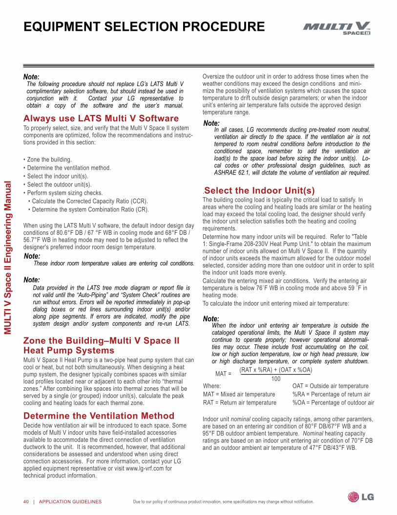
Due to our policy of continuous product innovation, some specifications may change without notification.40 | APPLIcATIOn GUIdeLIneS
MUL
TI V
Spa
ce II
Eng
inee
ring
Man
ual
always use latS Multi V SoftwareTo properly select, size, and verify that the Multi V Space II system components are optimized, follow the recommendations and instruc-tions provided in this section:
•Zone the building.•Determine the ventilation method.•Select the indoor unit(s).•Select the outdoor unit(s).•Perform system sizing checks.•Calculate the Corrected Capacity Ratio (CCR).•Determine the system Combination Ratio (CR).
When using the LATS Multi V software, the default indoor design day conditions of 80.6°F DB / 67 °F WB in cooling mode and 68°F DB / 56.7°F WB in heating mode may need to be adjusted to reflect the designer's preferred indoor room design temperature.
Zone the building–Multi V Space ii heat Pump SystemsMulti V Space II Heat Pump is a two-pipe heat pump system that can cool or heat, but not both simultaneously. When designing a heat pump system, the designer typically combines spaces with similar load profiles located near or adjacent to each other into “thermal zones.” After combining like spaces into thermal zones that will be served by a single (or grouped) indoor unit(s), calculate the peak cooling and heating loads for each thermal zone.
Determine the Ventilation MethodDecide how ventilation air will be introduced to each space. Some models of Multi V indoor units have field-installed accessories available to accommodate the direct connection of ventilation ductwork to the unit. It is recommended, however, that additional considerations be assessed and understood when using direct connection accessories. For more information, contact your LG applied equipment representative or visit www.lg-vrf.com for technical product information.
oversize the outdoor unit in order to address those times when the weather conditions may exceed the design conditions and mini-mize the possibility of ventilation systems which causes the space temperature to drift outside design parameters; or when the indoor unit’s entering air temperature falls outside the approved design temperature range.
.Select the indoor unit(s)The building cooling load is typically the critical load to satisfy. In areas where the cooling and heating loads are similar or the heating load may exceed the total cooling load, the designer should verify the indoor unit selection satisfies both the heating and cooling requirements. Determine how many indoor units will be required. Refer to "Table 1: Single-Frame 208-230V Heat Pump Unit." to obtain the maximum number of indoor units allowed on Multi V Space II. If the quantity of indoor units exceeds the maximum allowed for the outdoor model selected, consider adding more than one outdoor unit in order to split the indoor unit loads more evenly.Calculate the entering mixed air conditions. Verify the entering air temperatureisbelow76˚FWBincoolingmodeandabove59˚Finheating mode. To calculate the indoor unit entering mixed air temperature:
Indoor unit nominal cooling capacity ratings, among other paramters, are based on an entering air condition of 80°F DB/67°F WB and a 95°F DB outdoor ambient temperature. Nominal heating capacity ratings are based on an indoor unit entering air condition of 70°F DB and an outdoor ambient air temperature of 47°F DB/43°F WB.
EQuiPMEnt SElEction ProcEDurE
In all cases, LG recommends ducting pre-treated room neutral, ventilation air directly to the space. If the ventilation air is not tempered to room neutral conditions before introduction to the conditioned space, remember to add the ventilation air load(s) to the space load before sizing the indoor unit(s). Lo-cal codes or other professional design guidelines, such as ASHRAE 62.1, will dictate the volume of ventilation air required.
These indoor room temperature values are entering coil conditions.
The following procedure should not replace LG’s LATS Multi V complimentary selection software, but should instead be used in conjunction with it. Contact your LG representative to obtain a copy of the software and the user’s manual.
Data provided in the LATS tree mode diagram or report file is not valid until the “Auto-Piping” and “System Check” routines are run without errors. Errors will be reported immediately in pop-up dialog boxes or red lines surrounding indoor unit(s) and/or along pipe segments. If errors are indicated, modify the pipe system design and/or system components and re-run LATS.
(RAT x %RA) + (oAT x %oA)100
Where:MAT = Mixed air temperatureRAT = Return air temperature
oAT = outside air temperature%RA = Percentage of return air%oA = Percentage of outdoor air
MAT =
When the indoor unit entering air temperature is outside the cataloged operational limits, the Multi V Space II system may continue to operate properly; however operational abnormali-ties may occur. These include frost accumulating on the coil, low or high suction temperature, low or high head pressure, low or high discharge temperature, or complete system shutdown.

Due to our policy of continuous product innovation, some specifications may change without notification. Due to our policy of continuous product innovation, some specifications may change without notification. APPLIcATIOn GUIdeLIneS | 41
Installation & Layout B
est Practices
EQuiPMEnt SElEction ProcEDurE
To determine an indoor unit’s peak capacity using LATS, the system’sCombinationRatiomustbe≤100%.Ifthesystemis designed with a Combination Ratio above 100%, temporarily select anoutdoorunitthatdrivesthecombinationratio≤100%.Recordtheindoor unit corrected capacity cooling and heating values.
Capacity CorrectionThe corrected cooling/heating capacity is different from the nominal cooling/heating capacity. The corrected capacity reported by LATS includes changes in unit performance after considering refrigerant line pressure drop, the system's Combination Ratio (CR), and the effect design ambient operating conditions has on the system’s cooling capability. Depending on the location of the building, additional capacity correction factors may need to be applied to the corrected capacity values provided by LATS.
Altitude Correctionon air-cooled systems, the impact of air density must be considered on systems installed at a significant altitude above sea level. To cal-culate the effect on the indoor unit’s cooling capacity, manually apply locally accepted altitude correction factors to the IDU capacities.
Minimum Air Change Requirements Avoid over-sizing indoor units in an attempt to increase the air exchange rate in the space. VRF systems are designed for minimum airflow over the coil to maximize latent capacity while cooling, maintain a comfortable, consistent discharge air tempera-ture while heating, and minimize fan motor power consumption. In extreme cases, over-sizing indoor units may compromise the outdoor unit’s ability to effectively match the space load(s).
Check the Indoor Unit Selection(s)Verify the sensible (and total) corrected cooling capacity. For each indoor unit the corrected capacity must be at least equal to the sum of the appropriate cooling design day space load(s) (plus ventilation load, if applicable) for the space(s) served by the indoor unit. Verify the corrected heating capacity. For each indoor unit, the corrected capacity must be at least equal to the sum of the heating design day space load (plus ventilation load, if applicable) for all spaces served by the indoor unit.
Select the outdoor unitAfter all indoor units are properly sized to offset the applicable loads in each space, begin the selection of the outdoor unit by choosing a size that meets both the block load cooling requirement and offsets the sum of the peak heating load. (only one size is currently avail-able for the Multi V Space II outdoor unit.)After making an outdoor unit selection, look up the outdoor unit’s corrected cooling and heating capacity at the specified ambient de-sign conditions. Use values reported by LATS or find it in the tables provided in the Performance Data section of this manual.
Capacity CorrectionFor air-cooled systems operating in cooling mode, a capacity correction factor may apply to account for the length of the system’s liquid pipe and elevation difference between the outdoor unit and the indoor unit(s). If the outdoor unit's corrected cooling capacity was derived from the LATS report, the elevation difference correction factor has already been applied. If the corrected cooling capacity was found using corrected capacity tables found in the Performance Data section, apply the appropriate elevation difference factor found in Table 15 and Table 16 (choice of table depends on the architecture of the system design). Multiply the outdoor unit corrected cooling capacity by the elevation difference correction factor.
Frost AccumulationThe outdoor unit heating capacity may need to be adjusted for frost accumulation on air-cooled systems. If design day conditions are below the dew-point of the surrounding air, frost may not be a problem and no correction factor is needed. In certain weather conditions, however, frost may form and accumulate on the air-cooled outdoor unit coil and impact the coils ability to transfer heat. If significant frost accumulates on the outdoor unit coil, a defrost algorithm will start automatically. The timing between defrost periods is determined by the system's ability to achieve a target head pressure value. LATS will automatically apply a frost accumulation factor if the check box labeled “Defrost Factor” in the outdoor unit selection dialog box is marked. The dialog box can be accessed by double-clicking on the outdoor unit image. If checked, the corrected outdoor unit capacity provided by the LATS report and displayed on the tree mode piping diagram will already be adjusted for outdoor unit coil frost accumulation. If the corrected heating capacity was found using the Performance Data tables, the frost accumulation factor must be applied. Multiply the outdoor unit’s corrected heating capacity by the appropriate frost accumulation factor found in Table 13.
Check the Indoor Unit Selection(s)After applying the appropriate correction factors to the outdoor unit, verify the corrected cooling capacity is at least equal to the total building load (considering building diversity, if applicable), and the corrected heating capacity is at least equal to the sum of the peak heating loads for all spaces and/or thermal zones served by the system.
System Sizing checksCalculate the Corrected Capacity Ratio (CCR)The system’s CCR is defined as the sum of the space loads divided by the outdoor unit corrected capacity after all applicable correction factors are applied. Calculate this ratio for both the cooling and heating design days.
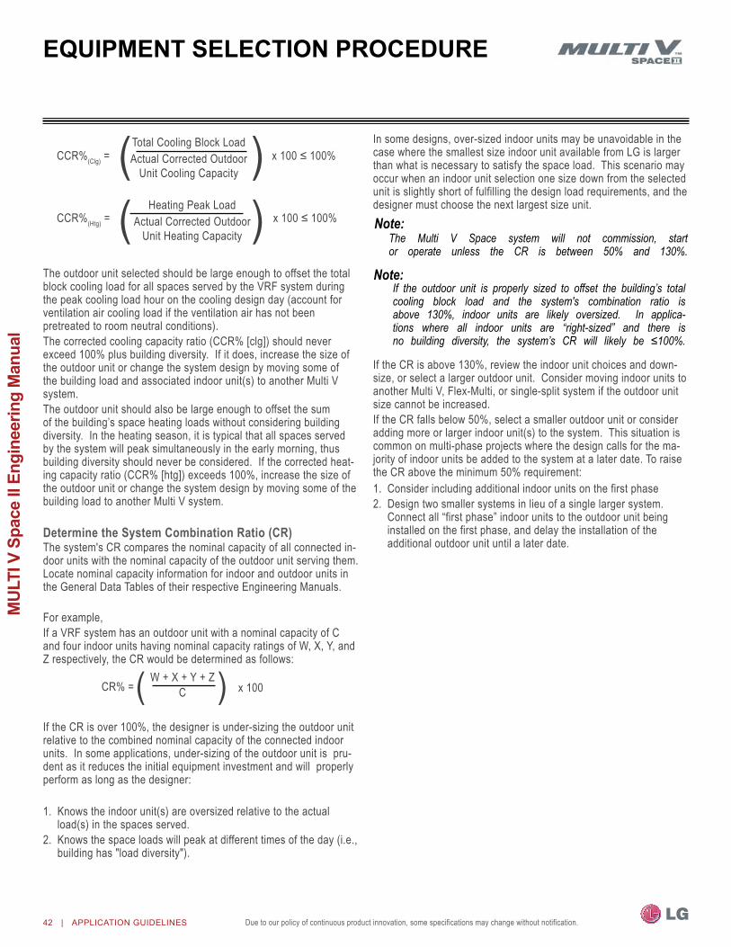
Due to our policy of continuous product innovation, some specifications may change without notification.42 | APPLIcATIOn GUIdeLIneS
MUL
TI V
Spa
ce II
Eng
inee
ring
Man
ual
The outdoor unit selected should be large enough to offset the total block cooling load for all spaces served by the VRF system during the peak cooling load hour on the cooling design day (account for ventilation air cooling load if the ventilation air has not been pretreated to room neutral conditions). The corrected cooling capacity ratio (CCR% [clg]) should never exceed 100% plus building diversity. If it does, increase the size of the outdoor unit or change the system design by moving some of the building load and associated indoor unit(s) to another Multi V system. The outdoor unit should also be large enough to offset the sum of the building’s space heating loads without considering building diversity. In the heating season, it is typical that all spaces served by the system will peak simultaneously in the early morning, thus building diversity should never be considered. If the corrected heat-ing capacity ratio (CCR% [htg]) exceeds 100%, increase the size of the outdoor unit or change the system design by moving some of the building load to another Multi V system.
Determine the System Combination Ratio (CR)The system's CR compares the nominal capacity of all connected in-door units with the nominal capacity of the outdoor unit serving them. Locate nominal capacity information for indoor and outdoor units in the General Data Tables of their respective Engineering Manuals.
For example,If a VRF system has an outdoor unit with a nominal capacity of C and four indoor units having nominal capacity ratings of W, X, Y, and Z respectively, the CR would be determined as follows:
If the CR is over 100%, the designer is under-sizing the outdoor unit relative to the combined nominal capacity of the connected indoor units. In some applications, under-sizing of the outdoor unit is pru-dent as it reduces the initial equipment investment and will properly perform as long as the designer:
1. Knows the indoor unit(s) are oversized relative to the actual load(s) in the spaces served.
2. Knows the space loads will peak at different times of the day (i.e., building has "load diversity").
In some designs, over-sized indoor units may be unavoidable in the case where the smallest size indoor unit available from LG is larger than what is necessary to satisfy the space load. This scenario may occur when an indoor unit selection one size down from the selected unit is slightly short of fulfilling the design load requirements, and the designer must choose the next largest size unit.
If the CR is above 130%, review the indoor unit choices and down-size, or select a larger outdoor unit. Consider moving indoor units to another Multi V, Flex-Multi, or single-split system if the outdoor unit size cannot be increased. If the CR falls below 50%, select a smaller outdoor unit or consider adding more or larger indoor unit(s) to the system. This situation is common on multi-phase projects where the design calls for the ma-jority of indoor units be added to the system at a later date. To raise the CR above the minimum 50% requirement:1. Consider including additional indoor units on the first phase 2. Design two smaller systems in lieu of a single larger system.
Connect all “first phase” indoor units to the outdoor unit being installed on the first phase, and delay the installation of the additional outdoor unit until a later date.
( )Total Cooling Block LoadActual Corrected outdoor
Unit Cooling CapacityCCR%(Clg) = x100≤100%
( )Heating Peak LoadActual Corrected outdoor
Unit Heating CapacityCCR%(Htg) = x100≤100%
EQuiPMEnt SElEction ProcEDurE
( )W + X + Y + ZCCR% = x 100
The Multi V Space system will not commission, start or operate unless the CR is between 50% and 130%.
If the outdoor unit is properly sized to offset the building’s total cooling block load and the system's combination ratio is above 130%, indoor units are likely oversized. In applica-tions where all indoor units are “right-sized” and there is no building diversity, the system’s CR will likely be ≤100%.

Due to our policy of continuous product innovation, some specifications may change without notification. Due to our policy of continuous product innovation, some specifications may change without notification. APPLIcATIOn GUIdeLIneS | 43
Installation & Layout B
est Practices
conclusions and recommendations•Always use LATS Multi V system design software to check a design. •Validate that each indoor unit is appropriately sized. Before validating, if the indoor units have been properly sized, the outdoor unit’s size mustbetemporarilyadjustedtomakethesystem’sCR≤100%.
•Using the indoor unit’s corrected capacity for cooling and heating provided by LATS and apply a correction factor for altitude if appropriate.
•Verify that the outdoor unit selection for each system is properly sized. Verify that the corrected capacity for cooling and heating provided by LATS is sufficient to offset the block building space load after applying additional correction factors for capacity and frost accumulation, if appropriate.
•For each Multi V system, calculate the cooling and heating design days1. Corrected Capacity Ratio (CCR).2. Combination Ratio (CR).
After these system checks are complete and design limitations are adhered, the system’s indoor and outdoor components should be properly sized and the system’s performance should now be optimized. The VRF system component size selections should be acceptable.
At any time, if further system design assistance is needed or you have a unique application you would like to discuss, contact your LG applied equipment representative for assistance.
Product Cooling Mode (°F DB) Heating Mode (°F WB)Multi V Space II Heat Pump 23 – 118 -4 – +60
1Equivalent pipe length distance between outdoor and indoor units is 25 feet and no elevation difference between outdoor and indoor units.2Reversing valve in cooling position.3Reversing valve in heating position.
Table 12: Published operating Temperature Ranges for LG Multi V Space II1.
EQuiPMEnt SElEction ProcEDurE
Frost accumulation Factor
operating temperature ranges
Table 13: outdoor Unit Frost Accumulation Factor (Heating)Entering DB (ºF) 19.4 23.0 26.6 32.0 37.4 41.0 44.6De-rate Factor 0.98 0.95 0.93 0.86 0.93 0.96 1.0
At 85% outdoor air relative humidity.The frost accumulation factor does not account for effects of snow accumulation restrictingairflowthroughtheoutdoor unit coil.
Model nominal Cooling (Btu/h)
Indoor Units
Max. Qty..Sum of Indoor Unit nominal Cooling Capacities (Btu/h)
Min. Capacity (Btu/h) (50%)1 Max. Capacity (Btu/h) (130%)2
Heat Pump (208-230V) ARUn053GF2 54,000 9 37,000 70,200
150% = Minimum Combination Ratio.2130% = Maximum Combination Ratio.
Table 14: Multi V Space II Heat Pump outdoor Unit / Indoor Unit Matching Limitations
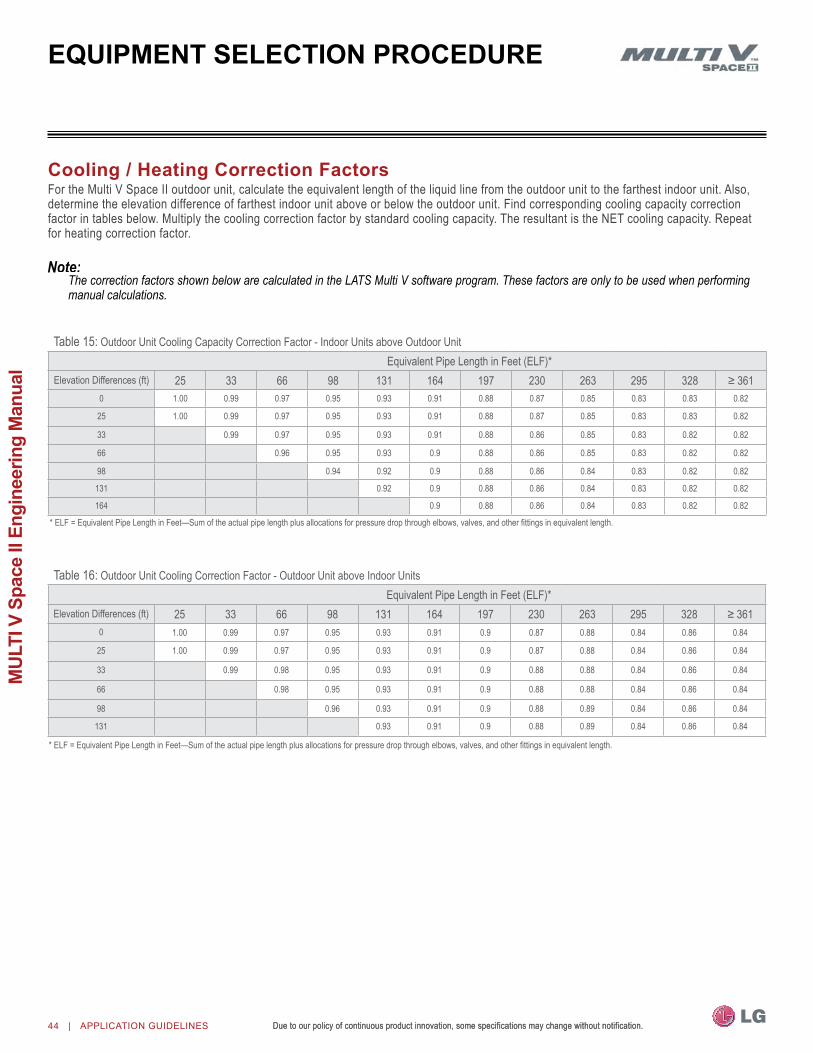
Due to our policy of continuous product innovation, some specifications may change without notification.Due to our policy of continuous product innovation, some specifications may change without notification.44 | APPLIcATIOn GUIdeLIneS
MUL
TI V
Spa
ce II
Eng
inee
ring
Man
ual
cooling / heating correction FactorsFor the Multi V Space II outdoor unit, calculate the equivalent length of the liquid line from the outdoor unit to the farthest indoor unit. Also, determine the elevation difference of farthest indoor unit above or below the outdoor unit. Find corresponding cooling capacity correction factor in tables below. Multiply the cooling correction factor by standard cooling capacity. The resultant is the nET cooling capacity. Repeat for heating correction factor.
EQuiPMEnt SElEction ProcEDurE
Table 15: outdoor Unit Cooling Capacity Correction Factor - Indoor Units above outdoor UnitEquivalent Pipe Length in Feet (ELF)*
Elevation Differences (ft) 25 33 66 98 131 164 197 230 263 295 328 ≥3610 1.00 0.99 0.97 0.95 0.93 0.91 0.88 0.87 0.85 0.83 0.83 0.82
25 1.00 0.99 0.97 0.95 0.93 0.91 0.88 0.87 0.85 0.83 0.83 0.82
33 0.99 0.97 0.95 0.93 0.91 0.88 0.86 0.85 0.83 0.82 0.82
66 0.96 0.95 0.93 0.9 0.88 0.86 0.85 0.83 0.82 0.82
98 0.94 0.92 0.9 0.88 0.86 0.84 0.83 0.82 0.82
131 0.92 0.9 0.88 0.86 0.84 0.83 0.82 0.82
164 0.9 0.88 0.86 0.84 0.83 0.82 0.82
*ELF=EquivalentPipeLengthinFeet—Sumoftheactualpipelengthplusallocationsforpressuredropthroughelbows,valves,andotherfittingsinequivalentlength.
*ELF=EquivalentPipeLengthinFeet—Sumoftheactualpipelengthplusallocationsforpressuredropthroughelbows,valves,andotherfittingsinequivalentlength.
Table 16: outdoor Unit Cooling Correction Factor - outdoor Unit above Indoor UnitsEquivalent Pipe Length in Feet (ELF)*
Elevation Differences (ft) 25 33 66 98 131 164 197 230 263 295 328 ≥3610 1.00 0.99 0.97 0.95 0.93 0.91 0.9 0.87 0.88 0.84 0.86 0.84
25 1.00 0.99 0.97 0.95 0.93 0.91 0.9 0.87 0.88 0.84 0.86 0.84
33 0.99 0.98 0.95 0.93 0.91 0.9 0.88 0.88 0.84 0.86 0.84
66 0.98 0.95 0.93 0.91 0.9 0.88 0.88 0.84 0.86 0.84
98 0.96 0.93 0.91 0.9 0.88 0.89 0.84 0.86 0.84
131 0.93 0.91 0.9 0.88 0.89 0.84 0.86 0.84
The correction factors shown below are calculated in the LATS Multi V software program. These factors are only to be used when performing manual calculations.
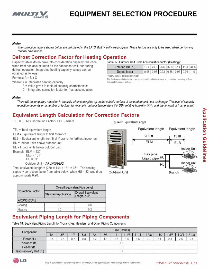
Due to our policy of continuous product innovation, some specifications may change without notification. Due to our policy of continuous product innovation, some specifications may change without notification. APPLIcATIOn GUIdeLIneS | 45
Application G
uidelines
Due to our policy of continuous product innovation, some specifications may change without notification.
Equivalent length calculation for correction FactorsTEL = (ELM x Correction Factor) + ELB, where
TEL = Total equivalent lengthELM = Equivalent length to first Y-branchELB = Equivalent length from first Y-branch to farthest indoor unitHU = Indoor units above outdoor unitHL = Indoor units below outdoor unitExample:ELM=230′ ELB=131′ HU=33′ outdoor Unit = ARUN053GF2Totalequivalentlength=(230′x1.0)+131′=361′.Thecoolingcapacitycorrectionfactorfromtablebelow,whenHU=33′wouldbeapproximately 0.90.
Correction Factoroverall Equivalent Pipe Length
Standard Application overall Equivalent Length 2951
ARUN053GF2Cooling 1.0 0.5Heating 1.0 0.2
Entering DB (ºF) 19.4 23.0 26.6 32.0 37.4 41.0 44.6Derate factor 0.98 0.95 0.93 0.86 0.93 0.96 1.0
Table 17: outdoor Unit Frost Accumulation factor (Heating)1Defrost correction Factor for heating operation
Figure 6: Equivalent Length
Component Size (Inches)1/4 3/8 1/2 5/8 3/4 7/8 1 1-1/8 1-1/4 1-3/8 1-1/2 1-5/8 1-3/4 2-1/8
Elbow (ft.) 0.5 0.6 0.7 0.8 1.2 1.3 1.5 1.6 1.8 2.0 2.1 2.3 2.5 2.8Y-branch (ft.) 1.6Header (ft.) 3.3
Heat Recovery Unit (ft.) 8.2
Capacity tables do not take into consideration capacity reduction when frost has accumulated on the condenser coil, nor during defrost operation. Integrated heating capacity values can be obtained as follows:Formula: A = B x CWhere: A = Integrated heating capacity B = Value given in table of capacity characteristics C = Integrated correction factor for frost accumulation
Equivalent Piping length for Piping components
1At 85% outdoor air relative humidity.The frost accumulation factor does not account for effects of snow accumulation restricting airflow through the outdoor unit coil.
Table 18: Equivalent Piping Length for Y-branches, Headers, and other Piping Components
EQuiPMEnt SElEction ProcEDurE
Outdoor Unit
Equivalent length
262 ft
Equivalent length
131ft
Branch
Indoor Unit
Indoor Unit
Gas pipe Liquid pipe
HU
HL
ELM ELB
The correction factors shown below are calculated in the LATS Multi V software program. These factors are only to be used when performing manual calculations.
There will be temporary reduction in capacity when snow piles up on the outside surface of the outdoor unit heat exchanger. The level of capacity reduction depends on a number of factors, for example, outdoor temperature (°F DB), relative humidity (RH), and the amount of frost present.

Due to our policy of continuous product innovation, some specifications may change without notification.46 | APPLIcATIOn GUIdeLIneS
MUL
TI V
Spa
ce II
Eng
inee
ring
Man
ual
builDing VEntilation DESign guiDE
ASHRAE 62.1 and local codes specify the minimum volume of outdoor air that must be provided to an occupied space. outdoor air is re-quired to minimize adverse health effects, and it provides acceptable indoor air quality for building occupants. The five methods of accom-plishing this with LG Multi V Space II systems are summarized here.
Method 1: Decoupled Dedicated outdoor air System (DDoaS)Provide a separate, dedicated outdoor-air system designed to filter, condition, and dehumidify ventilation air and deliver it directly to the conditioned space through a separate register or grille. This approach requires a separate independent ventilation duct system not associ-ated with the Multi V Space II system.
Advantages•Does not add additional heating or cooling loads to indoor units.•May be used with a full lineup of the indoor units.•If the outdoor air unit fails, the resulting untreated air will be readily
noticed by the occupants.•The outdoor air unit may supply “neutral” air to the occupant space
even when the Multi V indoor unit fan changes speed or cycles on and off. DDoAS controls do not have to be interlocked with the Multi V Space II system.
•In lieu of installing localized smaller outside air treatment equipment throughout the building, this method centralizes the ventilation air source making service and filter changes easier and less disruptive for the building occupants.
Disadvantages•Ceiling space is required to accommodate ductwork between the
centralized outdoor air unit and ceiling diffusers.
building Ventilation Design guide
•Indoor unit operation and performance will not be affected by the condition of outdoor air.
•Third-party demand control ventilation controls are more readily accommodated.
Figure 7: Decoupled Dedicated outdoor Air System
Outdoor Air Unit
Ceiling Diffuser Indoor Unit
Disclaimer Although we believe that these building ventilation methods have been portrayed accurately, none of the methods have been tested, verified, or evaluated by LG Electronics, U.S.A., Inc., In all cases, the designer, installer, and contractor should understand if the suggested method is used, it is used at their own risk. LG Electronics U.S.A., Inc., takes no responsibility and offers no warranty, expressed or implied, of merchantability or fitness of purpose if this method fails to perform as stated or intended.• For a complete copy of Standard 62.1-2010, refer to the American Standard of Heating and Air Conditioning Engineers (ASHRAE)
website at www.ashrae.org.• For more information on how to properly size a ventilation air pretreatment system, refer to the article, "Selecting DOAS Equipment with
Reserve Capacity" by John Murphy, published in the ASHRAE Journal, April 2010.
LG recommends using the DDOAS method in all installations.

Due to our policy of continuous product innovation, some specifications may change without notification. Due to our policy of continuous product innovation, some specifications may change without notification. APPLIcATIOn GUIdeLIneS | 47
Application G
uidelines
Method 3: unconditioned outdoor air Ducted to indoor unitsUntreated outdoor air is channeled through a duct system that is piped to the return air duct on concealed indoor units or to the chassis of 1-way and 4-way cassettes.
Advantages•May require less ductwork if indoor units are
placed near outdoor walls or a roof deck.•Controls must be interlocked to shut off the
outdoor air supply fan when the space is unoccupied.
•Third-party demand-control ventilation controls may be installed to regulate outdoor intake based on the Co2 levels of the occupied space.
Disadvantages •Fan(s) will be required to push outdoor air to the indoor unit. Indoor units are engineered
for low sound levels and are not designed to overcome the added static pressure caused by the outdoor air source ductwork.
•Ventilation air must be pre-filtered before mixing with the return air stream. LG indoor cassette models are configured to introduce the ventilation air downstream of the return air filter media.
•Ducted, 1-way, and 4-way cassette models are the only indoor units that accept the connection of an outdoor air duct to the unit case.
builDing VEntilation DESign guiDE
Method 2: unconditioned outdoor air (non-Ducted, natural Ventilation)natural ventilation devices, such as operable windows or louvers may be used to ventilate the building when local code permits. The open area of a window or the free area of a louver must meet the minimum percentage of the net occupied floor area.Advantages •occupants control the volume of the ventilation air manually.•Useful for historic buildings that have no ceiling space available for
outdoor air ductwork.•May be used with the full lineup of Multi V indoor units.
Disadvantages •In some locations, it may be difficult to control humidity levels when
windows are open.•Thermal comfort levels may be substandard when windows are
open.•Indoor units may have to be oversized to account for the added
heating and cooling loads when windows are open.•Provides outdoor air to perimeter spaces only. Additional mechani-
cal ventilation system may be required to satisfy requirements for interior spaces.
•outdoor air loads may be difficult to calculate since the quantity of outdoor air is not regulated.
•May affect indoor unit proper operation when open.
Figure 8: Unconditioned outdoor Air (non-Ducted)
Figure 9: Unconditioned outdoor Air Ducted to Indoor Units.
OA Wall CapDamper
Indoor Unit
Inline Fan with Filter
Outside air may flow backward through the return air-filter grille when the indoor unit fan speed slows or stops in response to changes in the space load. This may result in captured particulate on the filter media being blown back into the conditioned space.

Due to our policy of continuous product innovation, some specifications may change without notification.48 | APPLIcATIOn GUIdeLIneS
MUL
TI V
Spa
ce II
Eng
inee
ring
Man
ual
Method 4: unconditioned outdoor air (non-Ducted, Fan assisted Ventilation)When approved by local codes, the fan assisted ventilation method uses exhaust fans to remove air from the building, and outdoor air is drawn into occupied spaces through a wall louver or gravity roof intake hood. Supply fans can also be used to push the outdoor air into the space and building positive pressure will vent the exhaust air through louvers or roof-mounted exhaust hoods. outdoor air is neither cooled nor heated before entering the building.
Advantages •outdoor air may be manually controlled by the occupant or auto-
matic controls may be installed to open/close outdoor air dampers or to turn on/off ventilation fans.
•Useful for large open spaces like warehouses, garages, and workshops.
•outdoor air volume is a known quantity. Air loads may be easier to calculate since fans will regulate the amount of outdoor air.
•May be used with a full lineup of Multi V indoor units.
Disadvantages •In some locations of the country, it may be difficult to control
humidity levels while outdoor air louvers/hoods are opened.•Thermal comfort levels may be substandard when louvers/hoods
are opened.•Indoor units may have to be oversized to account for the added
heating/cooling loads when louvers/hoods are open.•Hot, cold, and/or humid areas may be present if the outdoor air is
not evenly distributed to the different spaces.
builDing VEntilation DESign guiDE
Disadvantages (Continued)•Mixed air conditions must be between a minimum of 59°F DB while operating in Heating mode and a maximum of 76°F WB while operating
in Cooling mode. Depending on the ventilation air volume requirement, the location choices are limited where untreated outside air may be introduced to the building using this method.
•Larger indoor units may be required to satisfy for additional outdoor air.•Motorized dampers may be required to prevent outdoor air flow through the indoor unit when the indoor unit is not operating.•An LG Dry Contact adapter may be necessary to interlock the motorized damper with the indoor unit.•While operating in Heating mode, the untreated outdoor air may delay the start of the indoor unit fan impacting building comfort.•In most cases, in lieu of using the factory mounted return-air thermistor on indoor units, a remote wall temperature sensor or zone controller
will be needed for each indoor unit to provide an accurate reading of the conditioned area temperature.
Figure 10: Unconditioned outdoor Air (non-Ducted)
OA Wall Louver
Damper
Roof Fan
This may result in loss of building pressurization control, increasing infiltration loads with adverse effects.

Due to our policy of continuous product innovation, some specifications may change without notification. Due to our policy of continuous product innovation, some specifications may change without notification. APPLIcATIOn GUIdeLIneS | 49
Application G
uidelines
Method 5: coupled Dedicated outdoor air (cDoa)A separate, dedicated outdoor air system delivers air directly to a Multi V indoor unit or to the return air duct system. After mixing with the return air stream, ventilation air passes through the indoor unit and into the conditioned space. The pretreatment system is capable of filtering, conditioning, and dehumidifying outdoor air to room neutral conditions.
Advantages•Separate ceiling registers or grilles for intro-
duction of the outside air to the conditioned space may be avoided.
Disadvantages•Ducted, 1-way, and 4-way cassette indoor units are the only models designed for direct
connection of an outside air duct.•The building occupant may not notice the outdoor air pretreatment system has malfunc-
tioned until the unconditioned outdoor air exceeds the indoor unit mixed air limits of 59°F DB for heating and 76°F WB for cooling.
•If the coil entering air condition limitation is exceeded, the indoor unit may malfunction and prevent the indoor unit from operating.
•If the outdoor air unit cooling or heating system fails, the malfunction may be masked by the indoor unit ramping up operating parameters to compensate for the failure.
•Motorized dampers may be required to prevent outdoor air from entering the indoor unit while the indoor unit has cycled off.
•An LG Dry Contact adapter is necessary to interlock the motorized damper with the indoor unit fan operation.
•In lieu of using the factory mounted return-air thermistor, a remote wall temperature sensor or zone controller may be required to provide an accurate conditioned space temperature reading.
builDing VEntilation DESign guiDE
Figure 11: Coupled Dedicated outdoor Air
Outdoor Air Unit
Outside air may flow backward through the return air-filter grille when the indoor unit fan speed is reduced or stops when the space load is satisfied. This may result in captured particulate on the filter media being blown back into the conditioned space.

Due to our policy of continuous product innovation, some specifications may change without notification.50 | APPLIcATIOn GUIdeLIneS
MUL
TI V
Spa
ce II
Eng
inee
ring
Man
ual
Selecting the best locationSelect a location for installing the outdoor unit that will meet the following conditions:•Where the unit will not be subjected to direct thermal radiation from other heat sources.•Where operating sound from the unit will not disturb inhabitants of surrounding buildings.•Where the unit will not be exposed to direct, strong winds.•Where there is enough strength to bear the weight of the unit.•Include space for drainage to ensure condensate flows properly out of the unit when it is in heating mode.•Include enough space for air flow and for service access.•To avoid the possibility of fire, do not install the unit in an area where combustible gas may generate, flow, stagnate, or leak.•Do not install the unit in a location where acidic solution and spray (sulfur) are often used.•Do not use the unit in environments where oil, steam, or sulfuric gas are present.•Install a fence to prevent vermin from crawling into the unit or unauthorized individuals from accessing it.
To ensure the outdoor unit operates properly, certain measures are required in locations where there is a possibility of heavy snowfall or severe windchill or cold: 1. Prepare for severe winter wind chills and heavy snowfall, even in areas of the country where these are unusual phenomena.2. Position the outdoor unit so that its airflow fans are not buried by direct, heavy snowfall. If snow piles up and blocks the airflow, the
system may malfunction.3. Place the outdoor unit on a raised platform at least 19-11/16 inches higher than the average annual snowfall for the area. In environments
where there is a possibility of heavy snow, the H frame height must be more than two (2) times the amount of average annual snowfall, and should not exceed the width of the outdoor unit. If the frame width is wider than the outdoor unit, snow may accumulate.
4. Install a snow protection hood.5. To prevent snow and heavy rain from entering the outdoor unit, install the suction and discharge ducts facing away from direct winds.
Additionally, the following conditions should be taken into considerations when the unit operates in defrost mode:•If the outdoor unit is installed in a highly humid environment (near an ocean, lake, etc.), ensure that the site is well-ventilated and has a lot
of natural light. (Example: Install on a rooftop.)•Sidewalks or parking lots near the outdoor unit may accumulate moisture after unit operates in defrost mode that can turn to ice.
The indoor unit may take longer to provide heat, or heating performance will be reduced in winter if the unit is installed:1. In a narrow, shady location.2. near a location that has a lot of ground moisture.3. In a highly humid environment.4. In an area in which condensate does not drain properly.
PlacEMEnt conSiDErationSHeat Pump Outdoor Units

Due to our policy of continuous product innovation, some specifications may change without notification. Due to our policy of continuous product innovation, some specifications may change without notification. APPLIcATIOn GUIdeLIneS | 51
Application G
uidelines
PlacEMEnt conSiDErationSMulti V Space II Heat Pump
Mounting PlatformThe underlying structure or foundation must be designed to support the weight of the unit. Avoid placing the unit in a low lying area where water may accumulate.
Any installation deficiency may cause unit to fall down, resulting in a personal injury.
general MountingSecurely attach the Space II unit as shown in Figure 12, using pad, base rails, or other mount-ing platform that is securely anchored to the ground or building structure. Refer to the dimen-sional drawing in the “Product Data” section, and follow the applicable local code for clearance, mounting, anchor, and vibration attenuation requirements.
Figure 12: outdoor Unit—Mounting Methods1
1All referenced materials are to be field-supplied. Images are not to scale. All dimensions ±0.25 inches.
A: Corners must be firmly attached, other-wise, the support will bend.B: Use a 3/8 inch anchor bolt.D: Insert cushion pad between outdoor unit and base support to ensure sufficient anti-vibration coverage.E: Pipe and wiring space.F: H-beam support.G: Concrete base support.
28 1/2
20 1/2
Foundation bolt executing method
8
Nut
3
3
8
Spring washer
Frame
Anti-vibrationmaterials
Four bolt are required3 thread ridgesH-Beam
Concretebase
4
G
Units = Inches
Avoid exposing the outdoor unit to steam, combustible gases, or other corrosive elements. Avoid exposing the unit to discharge from boiler stacks, chimneys, steam relief ports, other air conditioning units, kitchen vents, plumbing vents, and other sources of extreme temperature, gases, or sub-stances that may degrade performance or cause damage to the unit. When installing multiple outdoor units, avoid placing the units where discharge of one outdoor unit will blow into the inlet side of an adjacent unit.
• When deciding on a location to place the outdoor unit, be sure to choose an area where run-off from defrost mode will not accumulate and freeze on sidewalks or driveways.
• Don't use a tube or pipe for water in the base pan. Perform water drain processing by using the drain path.• Do not install the suction hole and discharge hole of the outdoor unit to face seasonal wind as this can cause freeze.
ambient air conditions
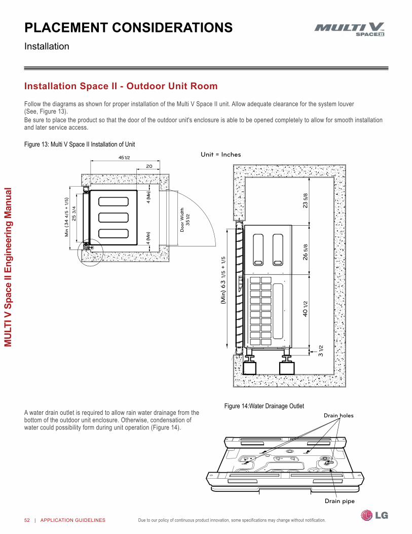
Due to our policy of continuous product innovation, some specifications may change without notification.52 | APPLIcATIOn GUIdeLIneS
MUL
TI V
Spa
ce II
Eng
inee
ring
Man
ual
Follow the diagrams as shown for proper installation of the Multi V Space II unit. Allow adequate clearance for the system louver (See, Figure 13).Be sure to place the product so that the door of the outdoor unit's enclosure is able to be opened completely to allow for smooth installation and later service access.
Figure 13: Multi V Space II Installation of Unit
A water drain outlet is required to allow rain water drainage from the bottom of the outdoor unit enclosure. otherwise, condensation of water could possibility form during unit operation (Figure 14).
Figure 14:Water Drainage outlet
PlacEMEnt conSiDErationSInstallation
installation Space ii - outdoor unit room
Drain holes
Drain pipe
20
45 1/2
Min
(3
4 4
/5 +
1/5
)
25
3/4
4 (M
in)4
(Min
)Unit = Inches
(Min
) 6
3 1
/5 +
1/5
3 1/
2
40 1/
226
5/8
23 5
/8
Doo
r W
idth
35
1/2

Due to our policy of continuous product innovation, some specifications may change without notification. Due to our policy of continuous product innovation, some specifications may change without notification. APPLIcATIOn GUIdeLIneS | 53
Application G
uidelines
PlacEMEnt conSiDErationS
Figure 15: Recommended Installation Space Clearance for Louver
Figure 16: Recommended Effective opening Ratio of Louver
Figure 15 shows the recommended clearance around the sides and top of the Multi V Space II louver
Do not bend the louver as shown in Figure 15 since this will disrupt the air circulation..
2623
1/2
38 1/
4
3 1/
4
Unit = Inches

54 | APPLIcATIOn GUIdeLIneS
MUL
TI V
Spa
ce II
Eng
inee
ring
Man
ual
Due to our policy of continuous product innovation, some specifications may change without notification.
This page intentionally left blank.
Due to our policy of continuous product innovation, some specifications may change without notification. Due to our policy of continuous product innovation, some specifications may change without notification. ReFRIGeRAnT deSIGn | 55
Refrigerant Piping
“latS Multi V Design Software” page 56“Design guideline Summary” page 57"Pipe Sizing" page 58"creating a balanced / Quality Piping System" page 61"Manual layout Procedure" page 62"lg Engineered y-branch Kits and header Kits" page 63"refrigerant charge" page 67"Selecting Field-Supplied copper tubing" page 68"refrigerant Piping System layout" page 71“cut-Sheets” page 77"Electrical connections" page 81
REFRIGERAnT PIPInG DESIGn & LAYoUT BEST PRACTICES

Due to our policy of continuous product innovation, some specifications may change without notification.56 | ReFRIGeRAnT deSIGn
MUL
TI V
Spa
ce II
Eng
inee
ring
Man
ual
The proper design and installation of the refrigerant piping system is a critical element of the Multi V Space II system. Multi V Space II requires two pipes between system components – a liquid line and a vapor line. A properly designed refrigerant piping system ensures that refrigerant is delivered to the evaporator coil’s electronic expan-sion valve (EEV) in a pure liquid state free of gas bubbles. A proper design also ensures a sufficient refrigerant gas flow rate in the vapor line that eliminates the possibility of refrigeration oil from collecting in the vapor lines.
refrigerant Piping Quality assuranceLG’s LATS Multi V software makes designing the refrigerant system easy. LATS Multi V is a Windows®-based application that assists the engineer in the design of the refrigeration distribution pipe system, verifies the design complies with pipe design limitations, applies capacity correction factors, and calculates the system refrigerant charge. The piping system can be entered manually into LATS from a one-line pipe diagram.The piping system can be engineered manually using the procedure outlined in the"Manual Layout Procedure" on page 62, however, the preferred method is to design the system using LG’s LATS Multi V software. To ensure that the refrigerant piping design meets LG’s quality standards, a LATS refrigerant piping design must be provided with every Multi V Space II order. Following the installation, if any changes or variations to the design are necessary, a new LATS file must be created and provided to LG prior to system commissioning to ensure the proper pipe size has not changed.
adjusting latS Multi V output for altitudeWhen a system is installed at elevations significantly above sea level, the designer must also consider the impact air density has on the capacity of the indoor and outdoor units. An Altitude Correction Factor must be manually applied to the indoor and water source unit data provided in the LATS report. Use locally accepted altitude cor-rection factors to adjust capacities.
Design choicesLATS Multi V software is flexible, offering the HVAC system engineer a choice of two design methods: CAD mode and Tree mode.CAD ModeUsing the CAD mode, the refrigerant pipe design and layout work is performed concurrently. Simply import a copy of a plan view drawing (.dwg format) for floor of the structure into LATS Multi V software. Multi V air-source units, heat recovery units, and indoor units can be selected from drag and drop lists and placed on the floor plan drawing(s), and interconnecting pipes between system compo-nents will be drafted directly on the drawing set. LATS will size the refrigerant piping, certify the design, and provide a detailed materi-als report and system schematic. Use the export feature to create a CAD file (.dxf format) that can subsequently be imported into the building design drawings.
•Import the building’s architectural CAD (.dwg and .dxf format).•Import building loads from an external file (.xls and .xlsx format).•Layout refrigerant piping directly onto an overlay of the building drawing.•Automatically calculates pipe segment lengths based on drawing layout.•Creates an export image file for import to the building drawing set
(.dxf format).•Generates a system engineering report (.xls or .xlsx format).
Tree ModeUsing the TREE mode, the engineer can quickly create a one- line schematic drawing of the Multi V system. Integration of the engineered pipe system into the building drawings is done at a later date by the draftsperson using standard drafting software tools.
•Import building loads from an external file (.xls format).•System components selected using an easy drag and drop
process.•Automatically analyzes and checks the design complies with most
piping design limitations.•Sizes refrigerant piping.•Generates a system engineering report (.xls format).
In either case, LATS Multi V software generates a report file (.xls format) containing project design parameters, cooling and heating design day system component performance, and capacity data. The report calculates the system combination ratio, calculates the system refrigerant charge, and provides detailed bill of material information including a list of Multi V outdoor units, air handlers, control devices, accessories, refrigerant pipe sizes segregated by building, by system, by pipe size, and by pipe segments.
Figure 17: LATS Pipe System Design Tool in Tree Mode
LATS Multi V Piping design Software
rEFrigErant PiPing DESign

Due to our policy of continuous product innovation, some specifications may change without notification. Due to our policy of continuous product innovation, some specifications may change without notification. ReFRIGeRAnT deSIGn | 57
Refrigerant Piping
rEFrigErant PiPing DESign
Device connection limitations•The minimum number of connected and operating indoor units to Multi V Space II systems is one (1), taking into consideration of the mini-
mum combination ratio.•The maximum number of indoor units on Multi V Space II outdoor heat pump is nine (9):
Table 19: Multi V Space II Refrigerant Piping System Limitations
Pipe Length(ELF = Equivalent Length of
pipe in Feet)
Longest total equivalent piping length ≤475feetLongest distance from outdoor unit (oDU)
to indoor unit (IDU) 230 feet (Actual) 296 feet (Equivalent)
Distance between fittings and indoor units ≥20inchesMinimum distance between Indoor unit to any Y-branch ≤131feetMinimum distance from indoor unit to Y-branch 3 feetMaximum distance between first Y-branch to farthestindoor unit 131 feet
Elevation (All Elevation Limitations are Measured in Actual
Feet)
If outdoor unit is above indoor unit 98.4 feetIf outdoor unit is below indoor unit 98.4 feetBetween any two indoor units 49 feet
one of the most critical elements of a Multi V Space II system is the refrigerant piping. The table below lists pipe length limits that must be followed in the design of a Multi V Space II refrigerant pipe system:
design Guideline Summary
Table 20: Equivalent Piping Length for Y-branches, Headers, and other Piping Components
Liquid Line Pipe design Parameters
Component Size (Inches)1/4 3/8 1/2 5/8 3/4 7/8 1 1-1/8 1-1/4 1-3/8 1-1/2 1-5/8 1-3/4 2-1/8
Elbow (ft.) 0.5 0.6 0.7 0.8 1.2 1.3 1.5 1.6 1.8 2.0 2.1 2.3 2.5 2.8Y-branch (ft.)1 1.6Header (ft.) 3.3
l Longest pipe length Equivalent pipe lengthA+f≤230ft A+f≤295.2ft
l Longest pipe length after 1st branchf≤131ft
h Differenceinheight(OutsideUnit↔IndoorUnit)H≤98.4ft
h Differenceinheight(IndoorUnit↔IndoorUnit)h≤49ft
Figure 18: Typical Y Branch Method.
Refrigerant piping systemY branch methodE xample : 5 Indoor Units
connectedⒶ : Outdoor UnitⒷ : 1st branch (Y branch) Ⓒ : Indoor Units
l 131
H
98
.4
h 49
Unit = Feet
L 230
*TotalPipelength=A+B+C+a+b+c+d+e≤475.7ft
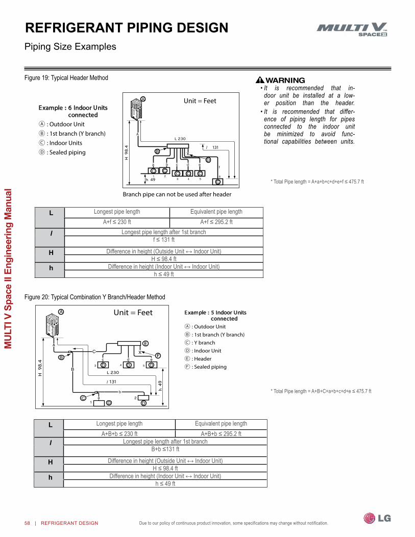
Due to our policy of continuous product innovation, some specifications may change without notification.58 | ReFRIGeRAnT deSIGn
MUL
TI V
Spa
ce II
Eng
inee
ring
Man
ual
Figure 20: Typical Combination Y Branch/Header Method
Figure 19: Typical Header Method
Piping Size examples
rEFrigErant PiPing DESign
131
h 4
9
L 230 H 9
8.4
E xample : 5 Indoor Units connected
Ⓐ : Outdoor UnitⒷ : 1st branch (Y branch) Ⓒ : Y branchⒹ : Indoor UnitⒺ : HeaderⒻ : Sealed piping
Unit = Feet
E xample : 6 Indoor Units connected
Ⓐ : Outdoor UnitⒷ : 1st branch (Y branch) Ⓒ : Indoor UnitsⒹ : Sealed piping
131
h 49
L 230
H 9
8.4
Branch pipe can not be used after header
Unit = Feet
• It is recommended that in-door unit be installed at a low-er position than the header.
• It is recommended that differ-ence of piping length for pipes connected to the indoor unit be minimized to avoid func-tional capabilities between units.
l Longest pipe length Equivalent pipe lengthA+f≤230ft A+f≤295.2ft
l Longest pipe length after 1st branchf≤131ft
h Differenceinheight(OutsideUnit↔IndoorUnit)H≤98.4ft
h Differenceinheight(IndoorUnit↔IndoorUnit)h≤49ft
*TotalPipelength=A+a+b+c+d+e+f≤475.7ft
*TotalPipelength=A+B+C+a+b+c+d+e≤475.7ft
l Longest pipe length Equivalent pipe lengthA+B+b≤230ft A+B+b≤295.2ft
l Longest pipe length after 1st branchB+b≤131ft
h Differenceinheight(OutsideUnit↔IndoorUnit)H≤98.4ft
h Differenceinheight(IndoorUnit↔IndoorUnit)h≤49ft

Due to our policy of continuous product innovation, some specifications may change without notification. Due to our policy of continuous product innovation, some specifications may change without notification. ReFRIGeRAnT deSIGn | 59
Refrigerant Piping
Pipe Sizing for Heat Pump Systems
oDU Capacity
(ton)
Pipe diameter Pipe length must be
≤295.2 feet
Pipe diameter Pipeheightmustbe(ODU↔IDU)
≤98.4 feet
Liquid pipe (inches oD)
Vapor pipe (inches oD)
Liquid pipe (inches oD
Vapor pipe (inches oD)
4.4 3/8Ø 3/4Ø 3/8Ø 3/4Ø
1For the first branch pipe, use the branch pipe that matches main pipe A diameter.
Downstream Total Capacity of IDUs
(Btu/h)1
Liquid pipe (inches oD)
Vapor pipe (inches oD)
≤19,100 1/4Ø 1/2Ø≤54,600 3/8Ø 5/8Ø≤76,400 3/8Ø 3/4Ø
Table 21: Main Pipe (A) Diameter from outdoor Unit to First Y-branch / Header Branch
Table 22: Refrigerant Pipe Diameter (B) from Y-branch to Y-branch / Header
Indoor Unit Capacity1
Liquid pipe (inches oD)
Vapor pipe (inches oD)
≤19,100 1/4Ø 1/2Ø≤54,600 3/8Ø 5/8Ø≤76,400 3/8Ø 3/4Ø
Table 23: Indoor Unit Connecting Pipe from Branch (B,C)
19,600-24,200 Btu/h 4-way 3 feet x 3 feet Cassette and 15,400-24,200 Btu/h High Static Ducted indoor units have 3/8Ø (liquid) and 5/8Ø (vapor).
rEFrigErant PiPing DESign
The following is an example of manual pipe size calculations. Designers are highly encouraged to use LATS instead of manual calculations.

Due to our policy of continuous product innovation, some specifications may change without notification.60 | ReFRIGeRAnT deSIGn
MUL
TI V
Spa
ce II
Eng
inee
ring
Man
ual
rEFrigErant PiPing DESignPipe Sizing for Multi V Space II Heat Pump Systems
Length Total pipe length Longest actual pipe length Equivalent pipe length1
A+ΣB+ΣC≤ 475 feet ≤230feet ≤558feet
ℓ Longest pipe length after first branch≤131feet(295feetconditionalapplication)
Elevation 1 Elevationdifferential(OutdoorUnit↔IndoorUnit)Height≤98feet
Height 1 Elevationdifferential(IndoorUnit↔IndoorUnit)Height≤49feet
DistancebetweenfittingsandIDU ≥20inchesDistancebetweenfittingsandY-branches/Headers ≥20inches
Distance between two Y-branches / Headers ≥20inches
Table 24: Pipe Capabilities
1For calculation purposes, assume equivalent pipe length of Y branches to be 1.6 feet, and the equivalent pipe length of headers to be 3.3 feet.
The following is an example of manual pipe size calculations. Designers are highly encouraged to use LATS instead of manual calculations.
• Connection piping from branch to branch cannot exceed the main pipe diameter (A) used by the outdoor unit.
• Y-branches and other header branches cannot be installed down-stream of the initial header branch.
• Indoor units must be installed at a position lower than the header.
• Install the header branch so that the pipe distances between the between the connected indoor units are minimized. Large differences in pipe distances can cause indoor unit performances to fluctuate.
• Always reference the LATS Multi V software report.

Due to our policy of continuous product innovation, some specifications may change without notification. Due to our policy of continuous product innovation, some specifications may change without notification. ReFRIGeRAnT deSIGn | 61
Refrigerant Piping
rEFrigErant PiPing DESign
refrigerant Piping System Quality assuranceTo ensure that the refrigerant piping design meets LG’s quality standards, a LATS refrigerant piping design software report must be provided with every Multi V Space II order. Following the installation, if any changes or variations to the design were necessary, an “as-built” LATS piping design software report must be provided to LG prior to system commissioning.
Systems that are close to the standard application limits may be converted into a conditional application by field changes to pipe equivalent lengths. User should always check the LATS report actual pipe layout versus pipe limits. The user may want to increase pipe lengths when conditions close to the standard application limits are present, forcing increased pipe diameters seen in conditional applications to be used and avoiding pipe changes due to field installation variations.
creating a balanced Piping System Unlike designing duct-work or chilled and hot water pipe systems where balancing dampers, ball valves, orifices, circuit setters, or other flow control devices can be installed to modify or balance the flow of cooling medium, these cannot be used in a VRF system. Therefore, variable refrigerant flow systems have to be designed to be “self balanced.” Balanced liquid refrigerant distribution is solely dependent on the designer choosing the correct pipe size for each segment. Pipe sizing considerations include pipe length, pipe segment pressure drop relative to other pipe segments in the system, type and quantity of elbows, bends present, fitting installation orientation, and end use device elevation differences.
creating a Balanced / Quality Piping System
It is imperative the designer avoids creating excessive pressure drop. When liquid refrigerant is subjected to excessive pressure drop, liquid refrigerant will change state and “flash” to vapor. Vapor present in a stream of liquid refrigerant before reaching the electronic expansion valve (EEV) results in a loss of system control and causes damage to the valve. The pipe system must be designed in a manner that avoids the creation of unwanted vapor.
Any field changes, such as re-routing, shortening or lengthening a pipe segment, adding or eliminating elbows and/or fittings, re-sizing, adding, or eliminating indoor units, changing the mounting height or moving the location of a device or fitting during installation should be done with caution and ALWAYS VERIFIED in LATS MULTI V SOFTWARE before supplies are purchased or installed. Doing so ensures profitable installation, eliminates rework, and ensures easier system commissioning.

Due to our policy of continuous product innovation, some specifications may change without notification.62 | ReFRIGeRAnT deSIGn
MUL
TI V
Spa
ce II
Eng
inee
ring
Man
ual
1. Choose the location of the indoor unit on the building drawing.
2. Choose the location of all Y-branch fittings, header fittings, and if possible, and draw them on the building drawings. Verify that all fittings are positioned per the guideline limitations set forth in "Y-Branch Kits" on page 63 and "Header Kits" on page 64.
3. Plan the route for interconnecting piping. Draw a one-line depiction of the pipe route chosen on the building drawings.
4. Calculate the actual length of each pipe segment and note it on the drawing.
5. Using the data obtained while selecting the system components on "Table 5: Summary Data—Surface Mounted / Floor Standing Indoor Units." on page 17, list the nominal cooling capacity next to each indoor unit on the drawing.
6. Starting at the indoor unit located farthest from the outdoor unit, sum the connected nominal capacity of all indoor units served by the pipe segment for each branch and runout pipe. Record these values next to each segment on the drawing.
7. Use tables in the "Design Guideline Summary" on page 57, determine the pipe size of the liquid and vapor lines of all pipes.
8. Starting at the indoor unit located farthest from the outdoor unit, sum the capacity of liquid line pipe segments located between the indoor unit and each Y-branch fitting, and header fitting. Record these values next to each Y-branch, and header fitting on the drawing.
9. Use tables at "Pipe Sizing for Heat Pump Systems" on page 59 to verify the pipe size of the liquid and vapor line(s) of all pipes.
10. Refer to "Y-Branch Kits" on page 63 and "Header Kits" on page 64 to determine the part number of each Y-branch, and header based on the connected downstream nominal capacity served.
11. Calculate the equivalent pipe length in feet of each pipe segment. Y-branch and header equivalent lengths should be totaled with the upstream segment only. Use equivalent pipe length data when it is provided with the field purchased fittings. If not available, use the data provided on "Cooling / Heating Correction Factors" on page 44 to estimate the equivalent length of field-provided pipe and fittings for each segment. Y-branch and header equivalent lengths are also found in "Table 37: Heat Pump Unit Refrigerant Pipe Connections (All Brazed Type)" on page 73. Equivalent lengths should be totaled with the upstream segment only.
12. Verify if the equivalent pipe length complies with the limitations in "Table 19: Multi V Space II Refrigerant Piping System Limitations" on page 57. If the limitations are exceeded, either reroute the pipe or change the location of the Y-branch fittings, and header fittings; and/or indoor unit locations so the design conforms with all limitations.
13. If adjusted as per Step 12 above, verify again if the length of the design complies with the limitations set in "Table 19: Multi V Space II Refrigerant Piping System Limitations" on page 57.
14. Verify that the manually sized pipe design is acceptable using LATS Multi V. When entering the length of pipe segments in LATS Multi V software, enter the equivalent pipe length. Account for the additional pressure drop created by elbows, valves, and other fittings present in each segment by adding their respective equivalent pipe length to the actual pipe length.
Manual Layout Procedure
rEFrigErant PiPing DESign

Due to our policy of continuous product innovation, some specifications may change without notification. Due to our policy of continuous product innovation, some specifications may change without notification. ReFRIGeRAnT deSIGn | 63
Refrigerant Piping
rEFrigErant PiPing DESign
LG Y-branch kits consist of:•Y-branches (liquid line, vapor lines).•Reducer fittings as applicable.•Molded clam-shell type insulation covers.
LG Header kits consist of:•Two Headers (one liquid line, one vapor line).•Reducer fittings as applicable.•Molded clam-shell type insulation covers.
LG engineered Y-branch Kits and Header Kits
y-branch KitsLG supplied Y-branches must be used at each transition. Field-supplied “T” fittings or “Y” branches will not be accepted. Each LG supplied Y-branch kit comes with two (2) Y-branches for indoor units, step-down pipe reducers, and insulation covers.
Y-branches may be installed in horizontal or vertical configurations. When installed vertically, position the Y-branch so the straight-through leg is ±3° of plumb. See Figure 22. When installed horizontally, posi-tion the Y-branch so the take-off leg is level and shares the same horizontal plane as the straight-through leg ±10° rotation as shown in Figure 23. There is no limitation on the number of Y-branches that can be installed, but there is a limitation on the number of indoor units connected to a single outdoor unit. "Table 14: Multi V Space II Heat Pump outdoor Unit / Indoor Unit Matching Limitations"Y-branches should always be installed with
the single port facing the outdoor unit, the two-port end facing indoor units (see Figure 21 Do not install Y-branches backwards as shown in Figure 23. Refrigerant flow cannot make U-turns through Y-branches. The first Y-branch kit must be located at least three (3) feet from the outdoor unit. Provide a minimum of 20 inches between a Y-branch and any other fittings or indoor unit piped in series.
It is recommended that when a Y-branch is located in a pipe chase or other concealed space, access doors should be provided for inspection access.
The equivalent pipe length of each Y-branch (1.6′)mustbeaddedtoeachpipesegmententered into LATS piping design software.
y-branch insulationEach Y-branch kit comes with clam-shell type peel-and-stick insula-tion jackets molded to fit the Y-branch fittings as shown in Figure 24—one for the liquid line, one for the vapor line(s).•Checkthefitofthe
Y-branch clam-shell insulation jacket after the Y-branch is installed.
•Mark the pipe where the insulation jacket ends.
•Remove the jacket. • Installfield-providedinsula-
tion on the three (3) pipes first.
•Peel the adhesive glue protector slip and install the clam-shell jacket over the fitting.
Figure 21: Y-branch Connections
Figure 22: Y-branch Installation Alignment SpecificationVerticalupconfiguration. Verticaldownconfiguration.
Figure 23:HorizontalConfigurationEndView±10°
Horizontal Plane
±10°
Branch LegStraight-through Leg
Y-branch Inlet
Figure 24: Y-branch Insulation and Pipe Detail
LG Y-branch and Header kits are highly engineered devices designed to evenly divide the flow of refrigerant, and are used to join one pipe segment to two or more segments.
Figure 25: Diagram of an Incorrect Y-branch Installation
Outdoor unit
Indoor unit
To next branch
To indoor unit
no SubstitutionsOnly LG supplied Y-branch and Header fittings can be used to join one pipe segment to two or more segments. Third-party or field-fabricated Tee’s, Y-fittings, Headers, or other branch fittings are not qualified for use with LG Multi V Space systems. The only field-provided fittings allowed in a Multi V Space piping system are 45° and 90° elbows.

Due to our policy of continuous product innovation, some specifications may change without notification.64 | ReFRIGeRAnT deSIGn
MUL
TI V
Spa
ce II
Eng
inee
ring
Man
ual
LG engineered Y-branch Kits and Header Kits
Header kits are intended for use where multiple indoor units are in the same vicinity and it would be better to “home-run” the run-out pipes back to a centralized location. If connecting multiple indoor units that are far apart, Y-branches may be more eco-nomical. "Single-Frame Heat Pump System" on page 64 for Header kit specifications and capacities.
Y-branches can be installed upstream between the Header and the outdoor unit, but a Y-branch cannot be installed between a Header and an indoor unit. Headers must be installed in a horizontal and level position with the distribution ports of the fitting in the same horizontal plane as the straight-through branch as shown in Figure 26.
When connecting indoor units to a Header, always connect the unit with the largest nominal capacity to the port closest to the outdoor unit. Then install the next largest indoor unit to the next port, working down to the smallest indoor unit. Do not skip ports. See Figure 26.
All indoor units must be mounted at an elevation below the Header fitting. All indoor units connected to a single Header fitting should be located with an elevation difference between indoor units that does not exceed 49 feet. If indoor units are located at an elevation the same as or above the Header fitting, do not use a Header. Instead, install a Y-branch fitting between the outdoor unit and the Header fitting, and connect the elevated indoor unit to the Y-branch.
header insulationEach Header kit comes with clam-shell type peel and stick insulation jackets molded to fit the Header fittings—one for the liquid line and one for the vapor line. See Figure 27.
header Kits
Figure 26: Header Kit—Horizontal Rotation Limit (Must be Installed Level with no Rotation).
Smaller IDUs
Connect IDUs
Largest IDU
Header Inlet
Header End View
+0.0
-0.0
rEFrigErant PiPing DESign
install correctly• Y-branches can be installed upstream between the Header and the outdoor unit, but a Y-branch cannot be installed between a header
and an indoor unit.• To avoid the potential of uneven refrigerant distribution through a header fitting, minimize the difference in equivalent pipe length
between the header fitting and each connected indoor unit.
Figure 27: Header Insulation and Pipe Detail
LG supplied insulation jacketLG supplied headerField supplied copper pipe
Field supplied insulation
Field supplied copper pipe
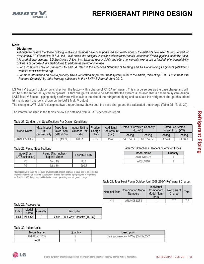
Due to our policy of continuous product innovation, some specifications may change without notification. Due to our policy of continuous product innovation, some specifications may change without notification. ReFRIGeRAnT deSIGn | 65
Refrigerant Piping
rEFrigErant PiPing DESign
LG Multi V Space II outdoor units ship from the factory with a charge of R410A refrigerant. This charge serves as the base charge and will not be sufficient for the system to operate. A trim charge will need to be added after the system is installed that is based on system design. LATS Multi V Space II piping design software will calculate the size of the refrigerant piping and calculate the refrigerant charge; this added trim refrigerant charge is shown on the LATS Multi V output. The example LATS Multi V design software report below shows both the base charge and the calculated trim charge (Table 25 - Table 30).
The information used in the tables below are obtained from a LATS-generated report.
Table 25:OutdoorUnitSpecificationsPerDesignConditions
Model nameMax. Indoor
Unit Connectivity
Max. Total over Load (kBtu/h/%)
Indoor Unit to outdoor Unit
Ratio
Product Charge (lbs.)
Additional Ref. Amount
(lbs.)
Rated / Corrected Capacity (kBtu/h)
Rated / Corrected Power Input (kW)
Cooling Heating Cooling HeatingARnU053GF2 9 70.5 (130%) 0.83:1 7.72 13.48 54.0 / 43.4 60.0 / 43.2 5.1 / 4.4 5.4 / 6.0
Table 26:PipingSpecificationsIndex (from
LATS selection)Piping Dia. (Inches)
Liquid : Vapor Length (Feet)1
P0 1/4 : 1/2 88.6P2 3/8 : 3/4 209.8
Table 27: Branches / Headers / Common PipesModel name QuantityARBLn03321 1
ARBL1010 1
1It is imperative to know the “as-built” physical length of each segment of liquid line, to calculate the total refrigerant charge required. An accurate “as built” field-verified piping diagram is required to verify within LATS that piping is within limits, proper pipe sizing, and refrigerant charge.
Table 29: Accessories
Model name Quantity DescriptionARnU053TRC2 9 Ceiling Cassette - 4-Way (5MBh_2X2
Total 9
Table 30: Indoor Units
Index Model name Quantity Description
IDU PT-UQC 9 Grille - Four-way Cassette (Tr, TQ)
nominal Tons Combination Model numbers
Individual Component Model num-
bers
Refrigerant Charge Total
4.4 ARUn053GF2 — 7.7 7.7
Table 28: Total Heat Pump outdoor Unit (208-230V) Refrigerant Charge
Disclaimer Although we believe that these building ventilation methods have been portrayed accurately, none of the methods have been tested, verified, or evaluated by LG Electronics, U.S.A., Inc., In all cases, the designer, installer, and contractor should understand if the suggested method is used, it is used at their own risk. LG Electronics U.S.A., Inc., takes no responsibility and offers no warranty, expressed or implied, of merchantability or fitness of purpose if this method fails to perform as stated or intended.• For a complete copy of Standards 15 and 34, refer to the American Standard of Heating and Air Conditioning Engineers (ASHRAE)
website at www.ashrae.org.• For more information on how to properly size a ventilation air pretreatment system, refer to the article, "Selecting DOAS Equipment with
Reserve Capacity" by John Murphy, published in the ASHRAE Journal, April 2010.

Due to our policy of continuous product innovation, some specifications may change without notification.66 | ReFRIGeRAnT deSIGn
MUL
TI V
Spa
ce II
Eng
inee
ring
Man
ual
rEFrigErant chargE
Figure 28: LATS Tree Diagram for Multi V Space II Refrigerant Piping
Determining the Total System Charge (Refer to Table 31, "System Refrigerant Charge Calculator (lbs.)")
1. Using the LATS Tree diagram, document the linear feet of straight liquid piping and the quantity and type of each fitting by pipe diameter into System Refrigerant Charge Calculator page 67.
2. Calculate the total linear feet of liquid line piping in the system. It is imperative to know the “as-built” physical length of each segment of liquid line to calculate the total refrigerant charge required. An accurate “as built” field-verified piping diagram is required to verify within LATS that piping is within limits, proper pipe sizing, and refrigerant charge. Record the values on lines 1–7.
3. Count the number of indoor units. Group them by model type and nominal capacity as indicated in the description field on lines 8–33 of the Calculator Table. Record the quantity of units in each group, multiply each by their specific correction factor, and add the sum in the Total (lbs.) column.
4. Count the number of heat recovery units, record the quantity, multiply by the specific correction factor, and record the sum in the Total (lbs.) column on line 34.
5. Sum the total values on lines 1-34 and place in the field labeled "Additional Refrigerant Charge Required" on line 34.6. Record the quantity of each outdoor unit frame, multiple total of each by their specific correction factor on line 35, and enter the total on
line 36 (Total Factory Refrigerant Charge).7. Add the Additional Refrigerant Charge Required to the Total Factory Refrigerant Charge. This is the Total System Charge. Record on line 37.

Due to our policy of continuous product innovation, some specifications may change without notification. Due to our policy of continuous product innovation, some specifications may change without notification. ReFRIGeRAnT deSIGn | 67
Refrigerant Piping
System Tag or ID____________________________________
Job name_______________________________________
Project Manager__________________________________
Date___________________________________________Line # Description Chassis I.D. Size CF (Ref.)1
1 Linear feet of 1/4" liquid line tubing1 — — 0.0152 Linear feet of 3/8" liquid line tubing1 — — 0.0413 Linear feet of 1/2" liquid line tubing1 — — 0.0794 Linear feet of 5/8" liquid line tubing1 — — 0.1165 Linear feet of 3/4" liquid line tubing1 — — 0.1796 Linear feet of 7/8" liquid line tubing1 — — 0.2387 Linear feet of 1" liquid line tubing1 — — 0.3238 Wall Mounted + Art Cool Mirror SE 7k to 15k 0.539 Wall Mounted + Art Cool Mirror S8, S5 18k to 24k 0.6210 1-Way Cassette TJ 7k to 12k 0.4411 2-Way Cassette TL 18k to 24k 0.3512 4-Way 2' x 2' Cassette TR 5k to 7k 0.4013 4-Way 2' x 2' Cassette TR 9k to 12k 0.5514 4-Way 2' x 2' Cassette TQ 15k to 18k 0.7115 4-Way 3' x 3' Cassette Tn 9k to 15k 1.0616 4-Way 3' x 3' Cassette TM 18k to 24k 1.4117 4-Way 3' x 3' Cassette TP 24k to 28k 1.0618 4-Way 3' x 3' Cassette Tn 36k 1.4119 4-Way 3' x 3' Cassette TM 42k to 48k 1.4120 High Static Ducted BH 7k to 24k 0.5721 High Static Ducted BG 15k to 42k 0.9722 High Static Ducted BR 48k 1.3723 High Static Ducted B8 76k to 95k 2.2024 Low Static Ducted, Low Static Ducted Bottom Return B1, B3 7k to 15k 0.3725 Low Static Ducted, Low Static Ducted Bottom Return B2, B4 18k to 24k 0.8226 Vertical / Horizontal Air Handling Unit nJ 18k to 24k 1.0427 Vertical / Horizontal Air Handling Unit nJ 30k 1.0428 Vertical / Horizontal Air Handling Unit nJ 36k 1.5729 Vertical / Horizontal Air Handling Unit nK 42k to 54k 2.0030 Ceiling Suspended VJ 18k to 24k 0.7731 Convertible Surface Mount—Ceiling/Wall VE 9k to 12k 0.2232 Floor Standing CE (U) 7k to 15k 0.3733 Floor Standing CF (U) 18k to 24k 0.8234 Additional Refrigerant Charge Required
35 outdoor Unit Factory Refrigerant Charge (To obtain factory refrigerant charge for each frame, see page 65.) 36a ARnU053GF2 53k 7.7
36 Total Factory Refrigerant Charge (sum of refrig. charge for all outdoor Units in the system)37 Total System Charge: Sum of Additional Refrigerant Charge Required to the Total Factory Refrigerant Charge
Table 31: System Refrigerant Charge Calculator (lbs.)
rEFrigErant chargE
1For refrigerant charge purposes, consider only the liquid line; ignore the vapor line(s).

Due to our policy of continuous product innovation, some specifications may change without notification.68 | ReFRIGeRAnT deSIGn
MUL
TI V
Spa
ce II
Eng
inee
ring
Man
ual
Copper is the only approved refrigerant pipe material for use with LG Multi V Space II commercial air conditioning products, and LG recommends hard-drawn rigid type “K” or “L”, or annealed-tempered, copper pipe. •Drawn temper (rigid) ACR copper tubing is available in sizes 3/8
through 2-1/8 inches (ASTM B 280, clean, dry, and capped). •Annealed temper (soft) ACR copper tubing is available in sizes 1/4
through 2-1/8 inches (ASTM B 280, clean, dry, and capped). Tube wall thickness should meet local code requirements and be approved for an operating pressure of 551 psi. If local code does not specify wall thickness, LG suggests using tube thickness per table below. When bending tubing, use the largest radii possible to reduce the equivalent length of installed pipe; also, bending radii greater than ten (10) pipe diameters can minimize pressure drop. Be sure no traps or sags are present when rolling out soft copper tubing coils.
oD (in) 1/4 3/8 1/2 5/8 3/4 7/8 1-1/8 1-3/8 1-5/8Material Rigid Type “K” or “L” -
Soft ACR Acceptable Rigid Type “K” or “L” only
Min. Bend Radius (in) .563 .9375 1.5 2.25 3.0 3.0 3.5 4.0 4.5
Min. WallThickness (in) .03 .03 .03 .03 .03 .03 .03 .04 .05
Table 32: ACR Copper Tubing MaterialType Seamless Phosphorous DeoxidizedClass UnS C12200 DHP
Straight Lengths H58 TemperCoils o60 Temper
Table 33: Piping Tube Thicknesses
Under normal operating conditions, the vapor pipe temperature of a Multi V Space II system can vary as much as 280°F. With this large variance in pipe temperature, the designer must consider pipe expansion and contraction to avoid pipe and fitting fatigue failures. Refrigerant pipe along with the insulation jacket form a cohesive unit that expands and contracts together. During system operation, thermal heat transfer occurs between the pipe and the surrounding insulation. If the pipe is mounted in free air space, no natural restriction to movement is present if mounting clamps are properly spaced and installed. When the refrigerant pipe is mounted underground in a utility duct stacked among other pipes, natural restriction to linear movement is present. In extreme cases, the restrictive force of surface friction between insulating jackets could become so great that natural expansion ceases and the pipe is “fixed” in place. In this situation, opposing force caused by change in refrigerant fluid/vapor temperature can lead to pipe/fitting stress failure.The refrigerant pipe support system must be engineered to allow free expansion to occur. When a segment of pipe is mounted between two fixed points, provisions must be provided to allow pipe expansion to naturally occur. The most common method is the inclusion of expansion Loop or U-bends. See "Figure 29: Coiled Expansion Loops and offsets" on page 70 Each segment of pipe has a natural fixed point where no movement occurs. This fixed point is located at the center point of the segment assuming the entire pipe is insulated in a similar fashion. The natural fixed point of the pipe segment is typically where the expansion Loop or U-bend should be. Linear pipe expansion can be calculated using the follow-ing formula:1. From Table 34, find the row corresponding with the actual length
of the straight pipe segment.2. Estimate the minimum and maximum temperature of the pipe.
In the column showing the minimum pipe temperature, look up the anticipated expansion distance. Do the same for the maximum pipe temperature.
3. Calculate the difference in the two expansion distance values. The result will be the anticipated change in pipe length.
Example: A Multi V Space II heat pump system is installed and the design shows that there is a 120 feet straight segment of tubing between a Y-branch and an indoor unit. In heating, this pipe transports hot gas vapor to the indoor units at 120°F. In cooling, the same tube is a suction line returning refrigerant vapor to the outdoor unit at 40°F. Look up the copper tubing expansion at each temperature and calculate the difference.
Vapor LineTransporting Hot Vapor: 120 ft. pipe at 120°F = 1.68 in. Transporting Suction Vapor: 120 ft. pipe at 40°F = .48 in. Anticipated Change in Length: 3.64 in. – 1.04 in. = 1.2 in.
Liquid LineThe liquid temperature remains the same temperature; only the direction of flow will reverse. Therefore, no significant change in length of the liquid line is anticipated.When creating an expansion joint, the joint height should be a minimum of two times the joint width. Although different types of expansion arrangements are available, the data for correctly sizing an Expansion Loop is provided in Table 35. Use soft copper with long radius bends on longer runs or long radius elbows for shorter pipe segments. Using the anticipated linear expansion (LE) distance calculated, look up the Expansion Loop or U-bend minimum design dimensions. If other types of expansion joints are chosen, design per ASTM B-88 Standards.
LE = C x L x (Tr – Ta) x 12
LE = Anticipated linear tubing expansion (in.)C = Constant (For copper = 9.2 x 10⁻⁶ in./in.°F)L = Length of pipe (ft.)TR = Refrigerant pipe temperature (°F)Ta = Ambient air temperature (°F)12 = Inches to feet conversion (12 in./ft.)
inStallation & layout bESt PracticESSelecting Field-Supplied copper Tubing
copper Expansion and contraction

Due to our policy of continuous product innovation, some specifications may change without notification. Due to our policy of continuous product innovation, some specifications may change without notification. ReFRIGeRAnT deSIGn | 69
Refrigerant Piping
Pipe Length1
Fluid Temperature °F35° 40° 45° 50° 55° 60° 65° 70° 75° 80° 85° 90° 95° 100° 105° 110° 115° 120° 125° 130°
10 0.04 0.04 0.05 0.06 0.06 0.07 0.08 0.08 0.09 0.09 0.10 0.10 0.11 0.11 0.11 0.12 0.13 0.14 0.15 0.1520 0.08 0.08 0.10 0.12 0.13 0.14 0.15 0.16 0.17 0.18 0.19 0.20 0.21 0.22 0.22 0.23 0.26 0.28 0.29 0.3030 0.12 0.12 0.15 0.18 0.20 0.21 0.23 0.24 0.26 0.27 0.29 0.30 0.32 0.33 0.32 0.35 0.39 0.42 0.44 0.4540 0.16 0.16 0.20 0.24 0.26 0.28 0.30 0.32 0.34 0.36 0.38 0.40 0.42 0.44 0.43 0.46 0.52 0.56 0.58 0.6050 0.20 0.20 0.25 0.30 0.33 0.35 0.38 0.40 0.43 0.45 0.48 0.50 0.53 0.55 0.54 0.58 0.65 0.70 0.73 0.7560 0.24 0.24 0.30 0.36 0.39 0.42 0.45 0.48 0.51 0.54 0.57 0.60 0.63 0.66 0.65 0.69 0.78 0.84 0.87 0.9070 0.28 0.28 0.35 0.42 0.46 0.49 0.53 0.56 0.60 0.63 0.67 0.70 0.74 0.77 0.76 0.81 0.91 0.98 1.02 1.0580 0.32 0.32 0.40 0.48 0.52 0.56 0.60 0.64 0.68 0.72 0.76 0.80 0.84 0.88 0.86 0.92 1.04 1.12 1.16 1.2090 0.36 0.36 0.45 0.54 0.59 0.63 0.68 0.72 0.77 0.81 0.86 0.90 0.95 0.99 0.97 1.04 1.17 1.26 1.31 1.35
100 0.40 0.40 0.50 0.60 0.65 0.70 0.75 0.80 0.85 0.90 0.95 1.00 1.05 1.10 1.08 1.15 1.30 1.40 1.45 1.50120 0.48 0.48 0.60 0.72 0.78 0.84 0.90 0.96 1.02 1.08 1.14 1.20 1.26 1.32 1.30 1.38 1.56 1.68 1.74 1.80140 0.56 0.56 0.70 0.84 0.91 0.98 1.05 1.12 1.19 1.26 1.33 1.40 1.47 1.54 1.51 1.61 1.82 1.96 2.03 2.10160 0.64 0.64 0.80 0.96 1.04 1.12 1.20 1.28 1.36 1.44 1.52 1.60 1.68 1.76 1.73 1.84 2.08 2.24 2.32 2.40180 0.72 0.72 0.90 1.08 1.17 1.26 1.35 1.44 1.53 1.62 1.71 1.80 1.89 1.98 1.94 2.07 2.34 2.52 2.61 2.70200 0.80 0.80 1.00 1.20 1.30 1.40 1.50 1.60 1.70 1.80 1.90 2.00 2.10 2.20 2.16 2.30 2.60 2.80 2.90 3.00220 0.88 0.88 1.10 1.32 1.43 1.54 1.65 1.76 1.87 1.98 2.09 2.20 2.31 2.42 2.38 2.53 2.86 3.08 3.19 3.30240 0.96 0.96 1.20 1.44 1.56 1.68 1.80 1.92 2.04 2.16 2.28 2.40 2.52 2.64 2.59 2.76 3.12 3.36 3.48 3.60260 1.04 1.04 1.30 1.56 1.69 1.82 1.95 2.08 2.21 2.34 2.47 2.60 2.73 2.86 2.81 2.99 3.38 3.64 3.77 3.90280 1.12 1.12 1.40 1.68 1.82 1.96 2.10 2.24 2.38 2.52 2.66 2.80 2.94 3.08 3.02 3.22 3.64 3.92 4.06 4.20300 1.20 1.20 1.50 1.80 1.95 2.10 2.25 2.40 2.55 2.70 2.85 3.00 3.15 3.30 3.24 3.45 3.90 4.20 4.35 4.50320 1.28 1.28 1.60 1.92 2.08 2.24 2.40 2.56 2.72 2.88 3.04 3.20 3.36 3.52 3.46 3.68 4.16 4.48 4.64 4.80340 1.36 1.36 1.70 2.04 2.21 2.38 2.55 2.72 2.89 3.06 3.23 3.40 3.57 3.74 3.67 3.91 4.42 4.76 4.93 5.10360 1.44 1.44 1.80 2.16 2.34 2.52 2.70 2.88 3.06 3.24 3.42 3.60 3.78 3.96 3.89 4.14 4.68 5.04 5.22 5.40380 1.52 1.52 1.90 2.28 2.47 2.66 2.85 3.04 3.23 3.42 3.61 3.80 3.99 4.18 4.10 4.37 4.94 5.32 5.51 5.70400 1.60 1.60 2.00 2.40 2.60 2.80 3.00 3.20 3.40 3.60 3.80 4.00 4.20 4.40 4.32 4.60 5.20 5.60 5.80 6.00420 1.68 1.68 2.10 2.52 2.73 2.94 3.15 3.36 3.57 3.78 3.99 4.20 4.41 4.62 4.54 4.83 5.46 5.88 6.09 6.30440 1.76 1.76 2.20 2.64 2.86 3.08 3.30 3.52 3.74 3.96 4.18 4.40 4.62 4.84 4.75 5.06 5.72 6.16 6.38 6.60460 1.84 1.84 2.30 2.76 2.99 3.22 3.45 3.68 3.91 4.14 4.37 4.60 4.83 5.06 4.97 5.29 5.98 6.44 6.67 6.90480 1.92 1.92 2.40 2.88 3.12 3.36 3.60 3.84 4.08 4.32 4.56 4.80 5.04 5.28 5.18 5.52 6.24 6.72 6.96 7.20500 2.00 2.00 2.50 3.00 3.25 3.50 3.75 4.00 4.25 4.50 4.75 5.00 5.25 5.50 5.40 5.75 6.50 7.00 7.25 7.50
1Pipe length baseline temperature = 0°F. "Expansion of Carbon, Copper and Stainless Steel Pipe," The Engineers' Toolbox, www.engineeringtoolbox.com.
Table 34: Linear Thermal Expansion of Copper Tubing in Inches
Selecting Field-Supplied copper Tubing
inStallation & layout bESt PracticES

Due to our policy of continuous product innovation, some specifications may change without notification.70 | ReFRIGeRAnT deSIGn
MUL
TI V
Spa
ce II
Eng
inee
ring
Man
ual
Selecting Field-Supplied copper Tubing
inStallation & layout bESt PracticES
Anticipated Linear Expansion (LE) (inches)
nominal Tube Size (oD) inches1/4 3/8 1/2 3/4 1 1-1/4 1-1/2
1/2R1 6 7 8 9 11 12 13L2 38 44 50 59 67 74 80
1R1 9 10 11 13 15 17 18L2 54 63 70 83 94 104 113
1-1/2R1 11 12 14 16 18 20 22L2 66 77 86 101 115 127 138
2R1 12 14 16 19 21 23 25L2 77 89 99 117 133 147 160
2-1/2R1 14 16 18 21 24 26 29L2 86 99 111 131 149 165 179
3R1 15 17 19 23 26 29 31L2 94 109 122 143 163 180 196
3-1/2R1 16 19 21 25 28 31 34L2 102 117 131 155 176 195 212
4R1 17 20 22 26 30 33 36L2 109 126 140 166 188 208 226
1R = Centerline Length of Pipe.2L = Centerline Minimum Radius (inches).
Large Tubing U-bend (>3/4 in.) Loop Small Tubing U-bend (<3/4 in.)
Figure 29: Coiled Expansion Loops and offsets
Large Tubing U-bend (>3/4 in.)
R
L
Table 35: Radii of Coiled Expansion Loops and Developed Lengths of Expansion offsets
Loop
RL
Small Tubing U-bend (<3/4 in.)
L

Due to our policy of continuous product innovation, some specifications may change without notification. Due to our policy of continuous product innovation, some specifications may change without notification. ReFRIGeRAnT deSIGn | 71
Refrigerant Piping
Main:ThepipingsegmentbetweentheoutdoorunitandthefirstY-branch.Branch: A segment of pipe between two Y-branches.Run-out: The segment of pipe connecting an indoor unit to a Y-branch.
Physical Pipe Length: Actual length of straight segment(s) of pipe.Equivalent Pipe Length: Actual length of pipe plus equivalent lengths of elbows, Y-branches, and valves.
1. Draft a one-line diagram of the proposed piping system connect-ing outdoor unit to indoor units. Follow the pipe limitations listed at "Table 19: Multi V Space II Refrigerant Piping System Limita-tions" on page 57.
2. Calculate the physical length of each pipe segment and note it on
the drawing.3. Calculate the equivalent pipe length of each pipe segment.4. Input the pipe lengths into the LATS software and perform “Auto
Pipe Sizing” check and “System Check”. LATS will automatically calculate pipe sizes.
using ElbowsField-supplied elbows are allowed as long as they are designed for use with R410A refrigerant. The designer, however, should be cautious with the quantity and size of fittings used, and must account for the additional pressure losses in equivalent pipe length calculation for each branch. The equivalent pipe length of each elbow must be added to each pipe segment in the LATS program. See Table 36 for equivalent lengths.
Table 36: Equivalent Piping Length for Y-branches, Headers, and other Piping Components
Field-Provided isolation ball ValvesLG recommends installing field-supplied ball valves with Schrader ports at each indoor unit. Full-port isolation ball valves with Schrader ports (positioned between valve and indoor unit) rated for use with R410A refrigerant should be used on both the liquid and vapor lines. If valves are not installed and a single indoor unit needs to be removed or repaired, the entire system must be shut down and evacuated. If isolation ball valves are installed, and an indoor unit needs to be repaired, the unaffected indoor units can remain operational with readdress-ing and the proper combination ratio (See “Determine the System Combination Ratio [CR]” on page 42). Reclamation of refrigerant, then, can be restricted to a single indoor unit. Position valves with a minimum distance of three (3) to six (6) inches of pipe on either side of the valve Y-branch, or header. Valves shall be easily accessible for service. If necessary, install drywall access doors or removable ceiling panels, and position the valves to face the access door or ceiling panel opening. Mount valves with adequate space between them to allow for placement of adequate pipe insulation around the valves. Recommended best practice is to clearly label and document locations of all service valves, Y-branches, and headers. The equivalent pipe length of each ball valve must be added to each pipe segment entered into LATS program. See "Table 36: Equivalent Piping Length for Y-branches, Headers, and other Piping Components" for equivalent lengths of ball valves.
Figure 30: Installing Piping Above and Below an obstacle
Above an obstacle.3X
Below an obstacle.Minimum
obstaclesWhen an obstacle, such as an I-beam or concrete T, is in the path of the planned refrigerant pipe run, it is best practice to route the pipe over the obstacle. If adequate space is not available to route the insulated pipe over the obstacle, then route the pipe under the obstacle. In either case, it is imperative the horizontal section of pipe above or below the obstacle be a minimum of three (3) times greater than the longest vertical rise (or fall) distance (Figure 30).
Definitions
layout Procedure
Refrigerant Piping System Layout
inStallation & layout bESt PracticES
Component Size (Inches)1/4 3/8 1/2 5/8 3/4 7/8 1 1-1/8 1-1/4 1-3/8 1-1/2 1-5/8 1-3/4 2-1/8
Elbow (ft.) 0.5 0.6 0.7 0.8 1.2 1.3 1.5 1.6 1.8 2.0 2.1 2.3 2.5 2.8Y-branch (ft.)1 1.6Header (ft.) 3.3
Above an obstacle Below an obstacle
1 Kit for ARUN Heat Pump systems contains two Y-branches: one for liquid and one for vapor; Kit for ARUB Heat Re-covery systems contains three Y-branches: one for liquid, one for low-pressure vapor, one for high-pressure vapor.

Due to our policy of continuous product innovation, some specifications may change without notification.72 | ReFRIGeRAnT deSIGn
MUL
TI V
Spa
ce II
Eng
inee
ring
Man
ual
inStallation & layout bESt PracticES
no Pipe Size SubstitutionsUse only the pipe size selected by the LATS Multi V pipe system design software. Using a different size is prohibited and may result in a system malfunction or failure to work at all.
in-line refrigeration componentsComponents such as oil traps, solenoid valves, filter-dryers, sight glasses, tee fittings, and other after-market accessories are not permit-ted on the refrigerant piping system between the outdoor unit and the indoor units. Multi V Space II air-source systems are provided with redundant systems that assure oil is properly returned to the compressor. Sight-glasses and solenoid valves may cause vapor to form in the liquid stream. over time, dryers may deteriorate and introduce debris into the system. The designer and installer should verify the refrigerant piping system is free of traps, sagging pipes, sight glasses, filter dryers, etc.
Pipe SupportsA properly installed pipe system should be adequately supported to avoid pipe sagging. Sagging pipes become oil traps that lead to equipment malfunction. Pipe supports should never touch the pipe wall; supports shall be installed outside (around) the primary pipe insulation jacket (see Figure 31). Insulate the pipe first because pipe supports shall be installed outside (around) the primary pipe insulation jacket. Clevis hangers should be used with shields between the hangers and insulation. Field provided pipe supports should be designed to meet local codes. If allowed by code, use fiber straps or split-ring hangers suspended from the ceiling on all-thread rods (fiber straps or split ring hangers can be used as long as they do not compress the pipe insulation). Place a second layer of insulation over the pipe insulation jacket to prevent chafing and compression of the primary insulation within the confines of the support pipe clamp.A properly installed pipe system will have sufficient supports to avoid pipes from sagging during the life of the system. As necessary, place supports closer for segments where potential sagging could occur. Maximum spacing of pipe supports shall meet local codes. If local codes do not specify pipe support spacing, pipe shall be supported:•Maximumoffivefeet(5′)oncenterforstraightsegmentsofpipeup
to 3/4" outside diameter size.•Maximumofsixfeet(6′)oncenterforpipeuptooneinch(1″)
outside diameter size.•Maximumofeightfeet(8′)oncenterforpipeuptotwoinches(2″)
outside diameter size.Wherever the pipe changes direction, place a hanger within twelve (12) inches on one side and within twelve to nineteen (12 to 19) inches of the bend on the other side as shown in Figure 32. Support piping at indoor units as shown in Figure 33. Support Y-Branch and Header fittings as shown in Figure 34 and Figure 35.
Figure 31: Pipe Hanger Details
Figure 32: Typical Pipe Support Location—Change in Pipe Direction
Figure 33: Pipe Support at Indoor Unit
Figure 34: Pipe Support at Y-branch Fitting.
Max. 12"
~ 12" – 19"
A
B
A + B ~ 12" – 19"
Max. 12" Max. 12"
Max. 12"
Max. 12"
Max. 12"
Figure 35: Pipe Support at Header Fitting
Refrigerant Piping System Layout

Due to our policy of continuous product innovation, some specifications may change without notification. Due to our policy of continuous product innovation, some specifications may change without notification. ReFRIGeRAnT deSIGn | 73
Refrigerant Piping
Refrigerant Piping System Layout
Pipe Sleeves at PenetrationsLG requires that all pipe penetrations through walls, floors, and pipes buried underground be properly insulated and routed through an appropriate wall sleeve of sufficient size to prevent compression of refrigerant pipe insulation and free movement of the pipe within the sleeve. Underground refrigerant pipe shall be routed inside a protective sleeve to prevent insulation deterioration.Figure 36: Pipe Sleeve options
inStallation & layout bESt PracticES
Model Liquid Conn. (inches) Vapor Conn. (inches)ARUn053FG2 3/8 3/4
Figure 37: Space Refrigerant Pipe option
Refrigerant piping can be connected through the access holes on the front panel of the Multi V Space II frame. •Use nitrogen at 2.8 psi flow during welding.•If nitrogen was not used during welding, oxidized contaminants
may build inside the piping and effect valve and condenser operation.
Table 37: Heat Pump Unit Refrigerant Pipe Connections (All Brazed Type)
Front Panel
DIRECTION OF PIPING/WIRING
Diameter of penetrations shall be determined by pipe diameter plus the thickness of the insulation.
avoid Pipe Damage• When routing field-provided piping inside the outdoor unit frame,
take care to avoid damage due to vibration. • Correctly route the piping so it does not make contact with the
compressor casing, terminal cover, or mounting bolts. Allow room for field installation.
• Properly insulate the liquid and vapor lines separately up to the point of connection inside the confines of the unit frame.
• Refer to Figure 37 for unit piping routing options, and Table 37 for unit pipe connection sizes.

Due to our policy of continuous product innovation, some specifications may change without notification.74 | ReFRIGeRAnT deSIGn
MUL
TI V
Spa
ce II
Eng
inee
ring
Man
ual
inStallation & layout bESt PracticESRefrigerant Piping System Layout
1. Remove the leak-prevention cap.2. Check if the liquid and vapor pipes are fully locked
(Figure 38).3. Vacuum out any remaining refrigerant or air through the
service port.
heat Pump unit Pipe connections
Guidelines and Cautions in Pipe Connection / Valve Operation1. Follow call outs of Figure 40 below while adhering to
these guidelines.2. At the Pipe Joint (1) in Figure ; securely perform brazen-
ing with a nitrogen blow into the service valve port. Releasing pressure: 2.9 psi or less.
3. At the Cap (2) in Figure; remove caps and then operate valves. After operation always secure the caps again, tightening at a torque of 221 lbf-in or more. Do not remove the internal part of the port!
4. At Service Ports (3) in Figure; complete the refrigerant vacuum and then charge it using the appropriate service ports to each valve. Always replace cap after comple-tion of work and tighten using a torque of 124 lbf-in or more.
5. The Liquid Pipe is shown at (4) on the figure.6. The Gas Pipe is shown at (5) on the figure.7. Additional information regarding these pipes is shown in
Figure 39.
Figure 38: Heat Pump outdoor Unit Pipe Connections.
Service Ports
Vapor Pipe
Liquid Pipe
The leak-prevention cap attached to the outdoor unit ser-vice valves must be removed before pipe installation.
If the pipe cap is not properly installed, the outdoor unit may leak refrigerant and the system will not operate properly.
Open Position Use cutter to cut the pipe and the valve for the correct length.Length should not be less than 2.8 inches.
CLOSE OPEN
Ball Valve(Gas Pipe) 22.2 : brazing type
19.05 : flare type
Ball Valve(Liquid Pipe)
Figure 39: Service Ports and Cutting Pipe Length
Figure 40: Ball Valve on Liquid and Gas Pipes
After completing work, be sure to securely tighten both service ports and caps in order to prevent leaks.

Due to our policy of continuous product innovation, some specifications may change without notification. Due to our policy of continuous product innovation, some specifications may change without notification. ReFRIGeRAnT deSIGn | 75
Refrigerant Piping
inStallation & layout bESt PracticES
refrigerant Safety StandardsASHRAE Standards 15 and 34 address refrigerant safety and the maximum allowable concentration of refrigerant in an occupied space. Re-frigerant will dissipate into the atmosphere, but a certain volume of air is required to safely dissipate the refrigerant. For R410A refrigerant, the maximum allowable concentration of refrigerant is 26 lbs./1,000 cubic feet of occupied spaces. Buildings with 24-hour occupancy allow half of that concentration.If a VRF system develops a refrigerant leak, the entire refrigerant charge of the system will dump into the area where the leak occurs. To meet ASHRAE Standards 15 and 34, the smallest room volume on the system must be calculated and compared to the maximum allowable concentration. If the concentration level is higher than allowed, the following are some design suggestions to eliminate the problem:•Add transfer grilles in the ceiling or walls of the smaller rooms to increase the volume of the room.
refrigerant Piping System insulationAll refrigerant piping including Y-branch and Header connections, field-provided isolation ball valves, service valves, and elbows shall be completely insulated using closed cell pipe insulation. The liquid and vapor lines must be insulated separately.To prevent heat loss/heat gain through the refrigerant piping, all refrigerant piping including liquid lines, high-pressure vapor lines, and low-pressurevaporlinesshallbeinsulatedseparately.Insulationshallbeaminimum1/2″thick,andthicknessneedstobeincreasedbasedonambient conditions and local codes. All insulation joints are to be glued with no air gaps. Insulation material shall fit snugly against the refrigeration pipe with no air space be-tween it and the pipe. Insulation passing through pipe hangers, inside conduit, and/or sleeves must not be compressed. Protect insulation inside hangers and supports with a second layer. All pipe insulation exposed to the sun and outdoor elements shall be properly protected with PVC, aluminum vapor barrier, or alternatively placed in a weather-resistant enclosure such as a pipe rack with a top cover; and meet local codes. LG-provided Y-branches are shipped from the factory with pre-formed peel-and-stick foam insulation jackets, with a 1.84 lb./ft.3 density,1/2″thickness,andmeetUL94MF-1flammability.The design engineer performs calculations to determine if the factory-supplied insulation jackets are sufficient to meet local codes and avoid sweating. Add additional insulation if necessary. Check the fit of the insulation jacket after the header fitting and all run-out pipes are installed. Mark all pipes at the point where the insulation jacket ends. Remove the jacket. Install field provided insulation on the run-out and main trunk pipes first. Install the LG-provided insulation plugs on the ends of all unused header ports. Peel the adhesive glue protector slip from the insulation jacket and install the clam-shell jacket over the fitting.
All joints are brazed in the field. Multi V Space II refrigeration system components contain very small capillary tubes, small orifices, electronic expansion valves, and heat exchangers that can easily become blocked. Proper system operation depends on the installer using best practices and utmost care while assembling the piping system.•While brazing, use a dry nitrogen purge operating at a minimum pressure of three
(3) psig and maintain a steady flow.•Blow clean all pipe sections with dry nitrogen prior to assembly.•Use a tubing cutter, do not use a saw to cut pipe. De-burr and clean all cuts
before assembly.•Store pipe stock in a dry place. Keep pipe capped and clean.•Use adapters to assemble different sizes of pipe.•Do not use flux, soft solder, or anti-oxidant agents.•Use a 15% silver phosphorous copper brazing alloy to avoid overheating and produce good flow.•Protect isolation valves, electronic expansion valves, and other heat-sensitive control components from excessive heat with a wet rag or a
heat barrier spray product
installation of refrigerant Piping / brazing Practices
Pressure-reducingValve
ValveTaping
Nitrogen
Pipe tobe brazed
Refrigerant Piping
Figure 41: Refrigerant Pipe Brazing.
Refrigerant Piping System Layout
It is imperative to keep the piping system free of contaminants and debris such as copper burrs, slag, or carbon dust during installation.

Due to our policy of continuous product innovation, some specifications may change without notification.76 | ReFRIGeRAnT deSIGn
MUL
TI V
Spa
ce II
Eng
inee
ring
Man
ual
Material Polyolefin FoamUL94FlameClassification HF-1
Density 1.84 lbs./ft.3
Thermal Conductivity .0208 Btu/h/ft. ºRThickness 1/2 inch
Table 38: nominal Capacity Range (Btu/h).Model Fitting Capacity
ARBLn01621 ≤72,000connectedcapacityARBLn03321 ≤144,000connectedcapacityARBLn07121 ≤336,000connectedcapacityARBLn14521 ≤432,000connectedcapacity
Table 39: Insulation Jacket Properties.
•LG indoor unit Y-branch fittings must be used with LG systems and be properly installed following the instruc-tions in the applicable LG manual. Field-supplied branch fittings are not permitted.
•Kit components must be kept free of debris and dry before installation.
•All Y-branch kits include a clam shell, peel-and-stick insulation jacket.
Vapor pipe Liquid pipeUnit: Inch
Models
ARBLN01621
ARBLN03321
ARBLN07121
ARBLN14521
I.D. 5/8
I.D. 5/8I.D. 5/8
16-1/415-3//8
I.D. 3/4
I.D. 3/4
I.D. 3/4
I.D. 3/4
O.D. 5/8
I.D. 1/2
I.D. 5/8
I.D. 5/8I.D. 5/8 I.D. 1/2
I.D. 1/2 I.D. 1/2
I.D. 1/2I.D. 1/2
I.D. 1/2 I.D. 1/2
I.D. 1/2
I.D. 1/2
I.D. 1/2O.D. 1/2
O.D. 1/2O.D. 1/2
I.D. 1/2
I.D. 1/2
I.D. 1/2
I.D. 1/2
I.D. 1/2
11-1/211-1/16
11-1/211-1/16
2-15/16 2-15/16
2-15/16
2-3/4
2-3/4
2-3/4
2-3/4
2-3/4
I.D. 5/8
I.D. 5/8
I.D. 1
I.D. 1
O.D. 1
3-3/16 4-3/8
4-3/84-3/8
4-3/8
13-1/1612-5/8
18-9/1620-3/8
4-15/16
14-5/815-1/2
3-5/16
3-5/16
5-1/8
I.D. 5/8I.D. 1-5/8
I.D. 1-5/8
I.D. 1-5/8
I.D. 1-1/2
I.D. 1-1/2
I.D. 1-1/2O.D. 1-1/2
O.D. 5/8
1 2
2
3
3
2
2
33
2
3
3
3
14-13/1615-215/16
4-3/4 4-3/4
4-3/4
4-3/4
3-9/16
3-9/16
I.D. 5/8
I.D. 5/8
2
3
1
2 1 3 3
16-3/817-1/2
O.D. 5/8
I.D. 5/8I.D. 3/4
I.D. 3/4 I.D. 3/4
I.D. 3/4
I.D. 3/4
I.D. 3/4
I.D. 3/4
I.D. 3/4
I.D. 5/8
I.D. 5/8I.D. 3/4
I.D. 3/4
O.D. 3/4
O.D. 3/4
O.D. 3/4O.D. 3/4
3-3/16
2
3
1
2 3 3
2
1 2
3-13/16
3-13/16
I.D. 7/8
I.D. 7/8
I.D. 7/8
I.D. 7/8
I.D. 7/8
I.D. 7/8
I.D. 7/8
I.D. 7/8
O.D. 7/8
O.D. 7/8
I.D. 7/8
I.D. 7/8
I.D. 1/4
I.D. 1/4I.D. 1/4
I.D. 1/4
I.D. 1/4
I.D. 1/4
I.D. 1/4)
1
1
1
1
I.D. 1-3/8
I.D. 1-3/8
I.D. 1-3/8
I.D. 1-3/8
O.D. 1-3/8
I.D. 1-1/8
I.D. 1-1/8
I.D. 1-1/8
I.D. 1-1/8
I.D. 1-1/8
O.D. 1-1/8
I.D. 1-1/8
O.D. 1-1/4I.D. 1-1/4
I.D. 1-1/4
I.D. 3/8I.D. 3/8
I.D. 3/8
I.D. 3/8
I.D. 3/8
I.D. 3/8
I.D. 3/8I.D. 3/8
I.D. 3/8
I.D. 3/8
O.D. 3/8
cut ShEEtSIndoor Unit Y-branch Kits (For ARUn Heat Pump Systems)
• Design pressure is 551 psig.• All dimensions in inches. Tolerance ±1/4 inch.• Images are not to scale.

Due to our policy of continuous product innovation, some specifications may change without notification. Due to our policy of continuous product innovation, some specifications may change without notification. ReFRIGeRAnT deSIGn | 77
Refrigerant Piping
•LG Headers serve as central connections for multiple runout pipe segments terminating at indoor units.
•Headers must be used with LG systems and be properly installed following the instructions in the applicable LG manual. Field-supplied headers are not permitted.
•Kit components must be kept free of debris and dry before installation.•All Header Kits include: •Insulation jacket (one each for vapor and liquid pipes)•Plugging tubes / Insulation for plugging tubes (see Table 41).
Model Fitting Capacity Port CapacityARBL054 (4 branch) ≤72,000connectedcapacity ≤54,300perportARBL057 (7 branch) ≤75,100connectedcapacity ≤54,300perport
ARBL1010 (10 branch) ≤172,200connectedcapacity ≤76,300perportARBL104 (4 branch) ≤305,200connectedcapacity ≤76,300perportARBL107 (7 branch) ≤534,000connectedcapacity <76,300 per port
ARBL2010 (10 branch) ≤560,000connectedcapacity ≤76,300perport
Table 40: nominal Capacity Range
Header Kits
cut-ShEEtS
Table 41: Plugging Tubes and Plugging Tube Insulation Amounts
Header KitsPlugging Tubes
Insulation for Plugging Tubes1/4Ø 1/2Ø 5/8Ø
ARBL054 (4 port) — — — —ARBL057 (7 port) 2 2 — 4
ARBL1010 (10 port) 2 2 2 6ARBL104 (4 port)ARBL107 (7 port) 2 2 2 6
ARBL2010 (10 port) 2 2 2 6
Table 42: Insulation Jacket PropertiesMaterial Polyolefin Foam
UL94FlameClassification HF-1Density 1.84 lbs./ft.3
Thermal Conductivity .0208 Btu/h/ft. ºRThickness 1/2 inch
Material CopperDesign Pressure 551 psig
Table 43: Fitting Properties
• All dimensions in inches. • Tolerance ±1/4 inch. • Images are not to scale.

Due to our policy of continuous product innovation, some specifications may change without notification.Due to our policy of continuous product innovation, some specifications may change without notification.78 | ReFRIGeRAnT deSIGn
MUL
TI V
Spa
ce II
Eng
inee
ring
Man
ual
Unit: Inch
4 branch
ARBL054
7 branch
ARBL057
4 branch
ARBL104
7 branch
ARBL107
10 branch
ARBL1010
10 branch
ARBL2010
Models Vapor pipe Liquid pipe14-3/16
21-1/4 21-1/4
4-3/4
I.D. 5/8
I.D. 1/2I.D. 1/2
I.D. 5/8
I.D. 5/8I.D. 3/4
4-3/414-3/16
I.D. 3/8I.D. 3/8
I.D. 1/4I.D. 1/4
I.D. 3/8I.D. 1/2
5-15/16
5-15/16
5-15/16 5-15/16
5-15/16
15-3/46-5/16
I.D. 5/8
I.D. 1/2
I.D. 3/4
I.D. 5/8
I.D 7/8I.D. 1-1/8 I.D. 1
4-3/44-3/4
4-3/4 4-3/4
4-3/4
4-3/4
4-3/4
4-3/4 4-3/4
4-3/4
I.D. 5/8
I.D. 1/2
I.D. 5/8
I.D. 1/2
I.D. 5/8I.D. 3/4
4-3/4I.D. 1/4
I.D. 3/8
I.D. 3/8I.D. 1/2
6-5/1622-7/8
I.D. 3/4
I.D. 5/8
ID15.88(5/8)
ID12.7(1/2)
I.D. 5/8
I.D. 1/2
I.D. 7/8I.D. 1-1/8 I.D. 1
27-9/16
4-3/4I.D. 1/4
I.D. 3/8I.D. 3/8
I.D. 1/4
I.D. 3/8I.D. 1/2
I.D. 5/8
I.D. 1/2
4-3/4
28-3/8
I.D. 1/4
I.D. 3/8
I.D. 3/8
I.D. 1/4
I.D. 1/2I.D. 3/8
4-1/421-1/2
27-9/16
I.D. 1/4
I.D. 3/8 I.D. 3/4I.D. 5/8
I.D. 3/8
I.D. 1/4
4-3/4
4-3/4
6-5/16
29-7/8
I.D. 3/4
I.D. 5/8
I.D. 7/8I.D. 1-1/8I.D. 1
7-3/16
30-9/16
I.D. 3/4
I.D. 5/8
I.D. 5/8
I.D. 1/2
I.D. 1-1/8I.D. 1-1/4I.D. 1-3/8
5-15/16
5-15/165-15/16
5-15/16
5-15/16
5-15/16
5-15/16
4-3/4
4-3/4
14-3/16
I.D. 3/8I.D. 3/8
I.D. 1/4I.D. 1/4
I.D. 3/8I.D. 1/2
Header Kits
cut ShEEtS

Due to our policy of continuous product innovation, some specifications may change without notification. Due to our policy of continuous product innovation, some specifications may change without notification. APPLIcATIOn GUIdeLIneS | 79
Wiring
Due to our policy of continuous product innovation, some specifications may change without notification.
ElEctrical connEctionS
Power supply1 Phase
208/230 V 60 Hz
3 Phase 4 Wires Power line(R, S, T, N)
Communication line (3 line): Wired remote control
Single Phase of power supply line(L, N)
Communication line (2 shield line): Between Indoor Unit and Outdoor Unit Power supply switch(Switch fuse : ELCB)
Power supply1 Phase
208/230 V 60 Hz
Power supply switch(Switch)
Pull Box(Installer Option)
The GND terminal is a '–' terminal for the central controller, not Ground Line
3 4 3 4 3 4
IDU V21 DNG2YRD1YRDUDOS INTERNET
B AB A B A
Figure 42:MultiVSpaceIIHeatPumpSystem—Daisy-ChainConfiguration
Figure 43: Multi V Space II Heat Pump System—Communication Wiring
Power Supply Wiring
• Ground wiring is required to prevent accidental electrical shock during current leakage, communication problems from electrical noise, and motor current leakage. Do not connect the ground line to the pipes.
• Install a main shutoff switch that interrupts all power sources simultaneously.• If the system operates in reversed phase, it may damage the compressors and other components. • If there is a possibility of reversed phase, phase loss, momentary blackout, or the power goes on and off while the system is
operating, install a field-supplied phase loss protection circuit.

Due to our policy of continuous product innovation, some specifications may change without notification.80 | APPLIcATIOn GUIdeLIneS
MUL
TI V
Spa
ce II
Eng
inee
ring
Man
ual
Communications cables are shielded, grounded at the outdoor unit(s) only. Maintain polarity throughout the communication network.
Figure 44: Multi V Space II Heat Pump System—Daisy-Chain Communications Cable Wiring
communications cable Wiring
ElEctrical connEctionS

Due to our policy of continuous product innovation, some specifications may change without notification. Due to our policy of continuous product innovation, some specifications may change without notification. APPLIcATIOn GUIdeLIneS | 81
Wiring
Figure 45: Multi V Space II Heat Pump System—Electrical Connections
ElEctrical connEctionS
MAIN PCB
INVERTER PCB
FAN PCB
TERMINAL BLOCK

Due to our policy of continuous product innovation, some specifications may change without notification.82 | TecHnIcAL dATA
MUL
TI V
Spa
ce O
utdo
or U
nit E
ngin
eerin
g M
anua
l
Multi V Space II Heat Pump Unit
MEchanical SPEciFicationS
generalLG Multi V Space II Variable Refrigerant Flow (VRF) comprises of a Heat Pump system with a single frame outdoor unit con-nected to up to 9 indoor units with a single refrigerant piping system connectable using factory designed and supplied Y-branches and headers, and having integrated controls. An LG Multi V Space II Heat pump system is a VRF system that can operate in either cooling or heating mode. LG components are manufactured in a facility registered to ISo 9001 and ISo 14001, which is a set of standards apply-ing to environmental protection set by the International organization for Standardiza-tion (ISo). The units are listed by Intertek Electrical Testing Laboratories (ETL) and bear the ETL label. Wiring in these units are in accordance with the national Electrical Code (nEC).
temperature rangesHeat Pump SystemsMulti V Space II can operate in heating only mode from -4°F to +60°F ambient wet bulb without additional low ambient controls.Multi V Space II can operate in cooling only mode from 23°F to +118°F ambient dry bulb.
casing / FrameMulti V Space II is constructed with galva-nized steel, bonderized and finished with powder coat baked enamel paint. Frames are completely factory assembled, piped and wired.
refrigerant SystemThe refrigeration system consists of a single refrigeration circuit and uses R410A refriger-ant. The outdoor unit is provided with factory installed components, including a refriger-
ant strainer, accumulator, hot gas bypass valve, four-way reversing valve, electronic controlled expansion valve (EEV), high and low side charging ports, high pressure safety switch, service valves, and intercon-necting piping. Also included is an integral subcooler assembly consisting of a double spiral tube-type subcooling heat exchanger and EEV providing refrigerant subcooling modulation up to 35ºF.
refrigeration oil controlMulti V Space II units have a compressor and controls to ensure sufficient oil supply is maintained, and that oil does not travel with the refrigerant.
compressorsThe Multi V Space II is equipped with one hermetic digitally controlled inverter driven rotary compressor to modulate capacity (variable from 21 to 100Hz, modulate in 1 Hz increments). Internal thermal overload protection is included.
outdoor unit coilMulti V Space II coils are of a nonferrous construction with louvered fins on copper tubing, and are protected with an integral metal guard. Coil fins have a factory applied corrosion resistant GoldFin™ material.
Fans and MotorsThe frame includes one direct drive, variable speed fan. The fan motor has inherent protection, permanently lubricated bearings, and is a variable speed with a maximum speed up to 813 rpm. Raised guards are provided to limit contact with moving parts.
The Multi V Space II unit has front discharge airflow. The unit has a static pressure capability up to0.2″WGwithDipswitchtoaccommodateadditional external static pressure.
ElectricalThe Multi V Space II Heat Pump unit is avail-able in a 208-230V 60 Hz, 1-phase power supply. The unit is capable of operating within voltage limits of ±10% rated voltage, and include overcurrent protection.
controlsThe Multi V Space II Heat Pump is factory wired with necessary electrical control com-ponents, integral microprocessors, printed circuit boards, thermistors, sensors, terminal blocks, and lugs for power wiring. Microprocessor-based algorithms provide component protection, soft-start capability, refrigeration system pressure, temperature, defrost, and ambient control.

Due to our policy of continuous product innovation, some specifications may change without notification. TecHnIcAL dATA | 83
Mechanical Specifications
%oA Percentage outdoor Air%RA Percentage Return AirABS Acrylonitrile Butadiene StyreneAC Air Conditioner/Alternate Current
ACP Advanced Control Platform
ASHRAE American Society of Heating, Refrigeration, and Air Conditioning Engineers
AHU Air Handling UnitAWG American Wire GaugeBLDC Brushless Digitally ControlledBtu/h British Thermal Units per hourCCR Corrected Capacity Ratio
CDoA Coupled Dedicated outdoor AirCFM Cubic Feet per MinuteCR Combination RatioCR Credit (LEED Related)DB Dry Bulb
dB(A) Decibels with “A” frequency weightingDDoAS Decoupled Dedicated outdoor Air Source
DFS Duct Free SystemDI Digital Input
Do Digital outputEEV Electronic Expansion ValveELF Equivalent Length in FeetETL Electrical Testing LaboratoriesIDU Indoor UnitISo International Standards organization
LEED Leadership in Energy and Environmental DesignMAT Mixed Air TemperatureMBh Thousand BTUs per hourMCA Maximum Circuit AmpacitynEC national Electrical CodeoAT outdoor Air TemperatureoDU outdoor UnitPDI Power Distribution IntegratorPI Power Input
RAT Return Air TemperatureRUR Running Unit RatioVAV Variable Air VolumeVRF Variable Refrigerant Flow
Table 44: Table of Acronyms
acronyMS
LG Electronics Commercial Air Conditioning Division 11405 old Roswell Road Alpharetta, Georgia 30009www.lg-vrf.com
20001747 ISO 9001: 2008
LG ELECTRONICS INC.
LG Electronics Commercial Products Support1-888-865-3026 USA
Follow the prompts for commercial A/C products.
Supersedes VRF-EM-BS-001-US 013M03 VRF-EM-BS-001-US_014A15