engineering graphics ii projection theory and multiview drawings prof. jon southen october 10, 2008
TRANSCRIPT
Engineering Graphics IIProjection Theory and Multiview Drawings
Prof. Jon Southen
October 10, 2008
Text Reference
Bertoline-Wiebe, Fundamentals of Graphics Communication, Chapter 5
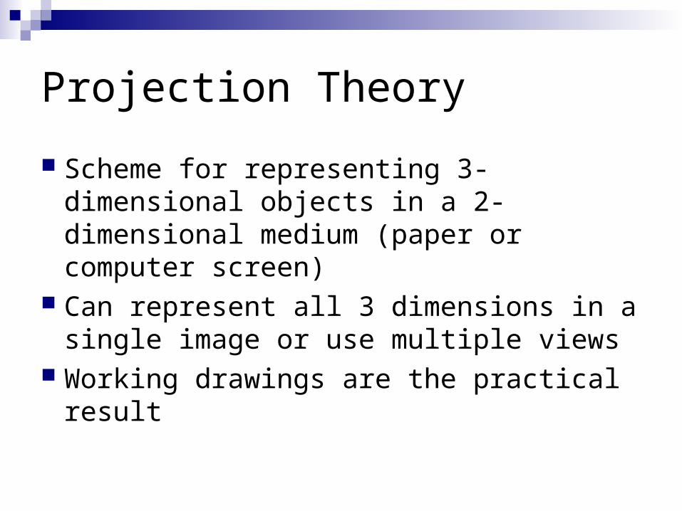
Projection Theory
Scheme for representing 3-dimensional objects in a 2-dimensional medium (paper or computer screen)
Can represent all 3 dimensions in a single image or use multiple views
Working drawings are the practical result
Projection Theory
Based on two concepts:Line of Sight
An imaginary ray of light between the observer’s eye and the object
Start at single point for perspective projections and are parallel in parallel projections (surprising!)
Plane of Projection An imaginary flat plane (paper, computer screen) upon
which the image created by the lines of sight is projected
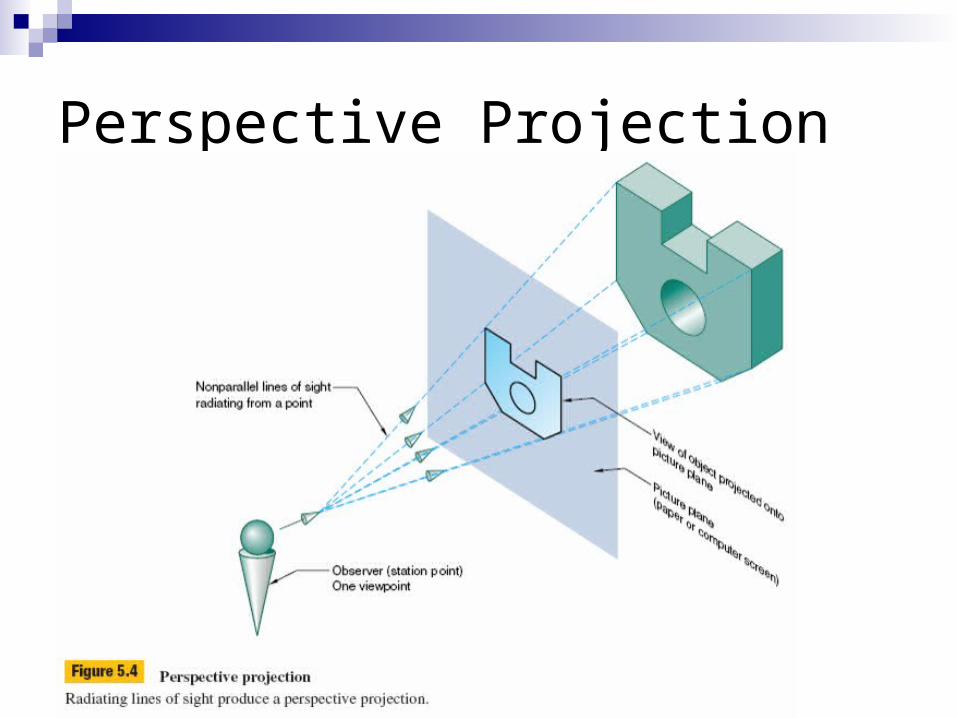
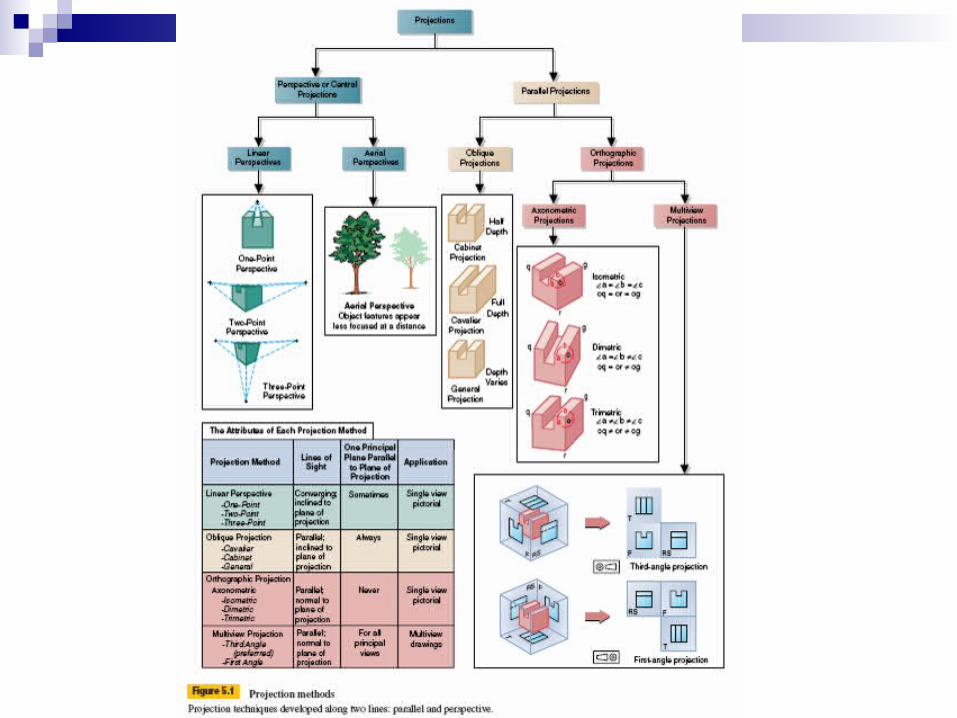
Perspective Projection
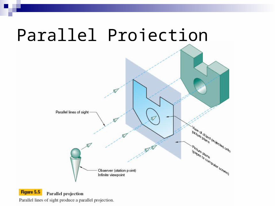
Parallel Projection
Projection Theory
Perspective projections mimic what the eye sees, but are more difficult to construct and do not show the true dimensions of the object
Parallel projections are most commonly used in engineering graphics
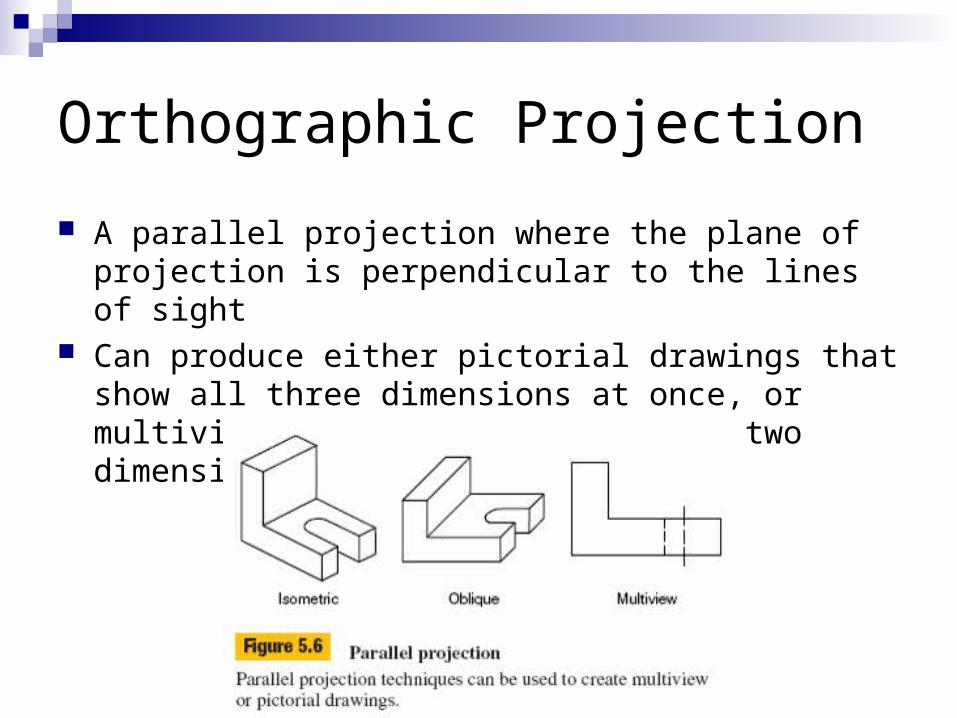
Orthographic Projection
A parallel projection where the plane of projection is perpendicular to the lines of sight
Can produce either pictorial drawings that show all three dimensions at once, or multiview drawings that show only two dimensions at a time
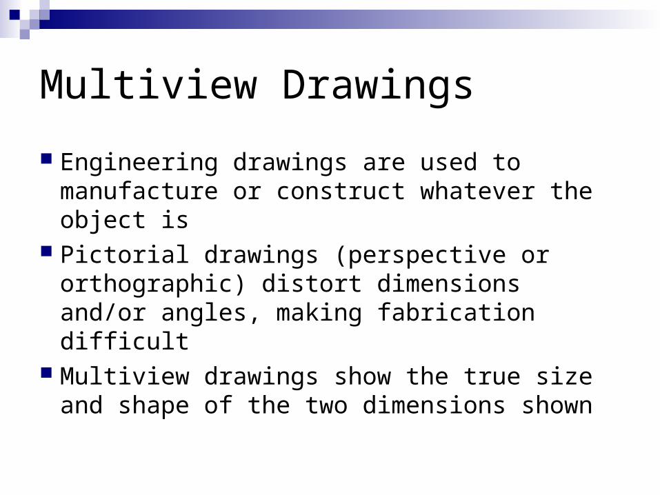
Multiview Drawings
Engineering drawings are used to manufacture or construct whatever the object is
Pictorial drawings (perspective or orthographic) distort dimensions and/or angles, making fabrication difficult
Multiview drawings show the true size and shape of the two dimensions shown

Pictorial Distortion
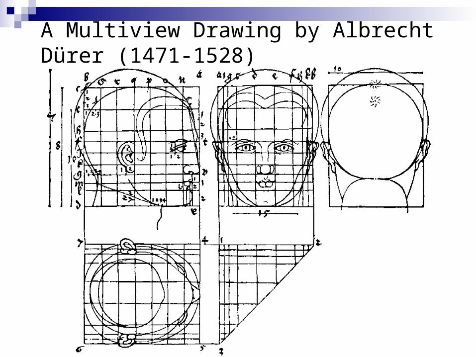
A Multiview Drawing by Albrecht Dürer (1471-1528)
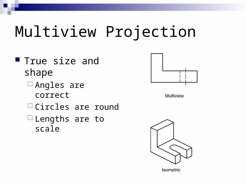
Multiview Projection
True size and shape Angles are correct Circles are round Lengths are to scale
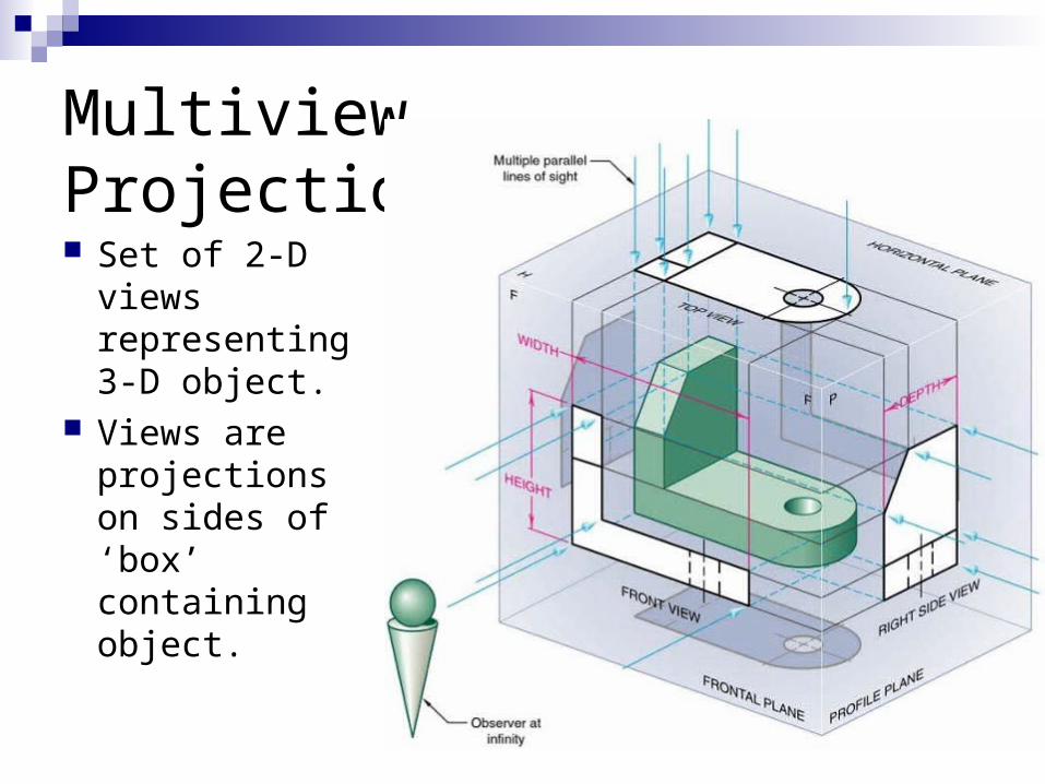
Multiview Projection Set of 2-D
views representing 3-D object.
Views are projections on sides of ‘box’ containing object.
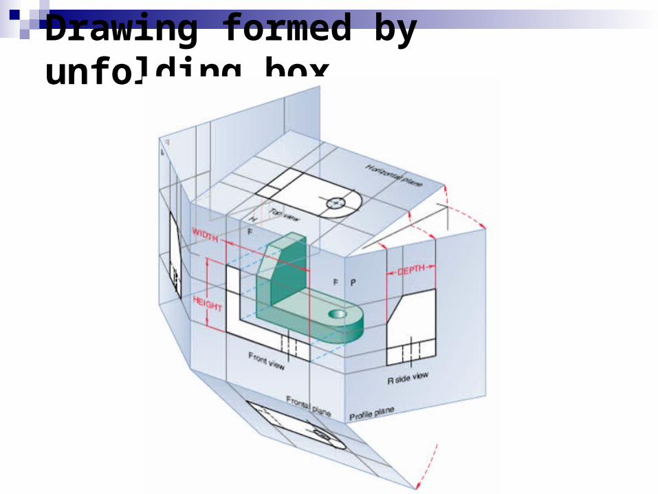
Drawing formed by unfolding box
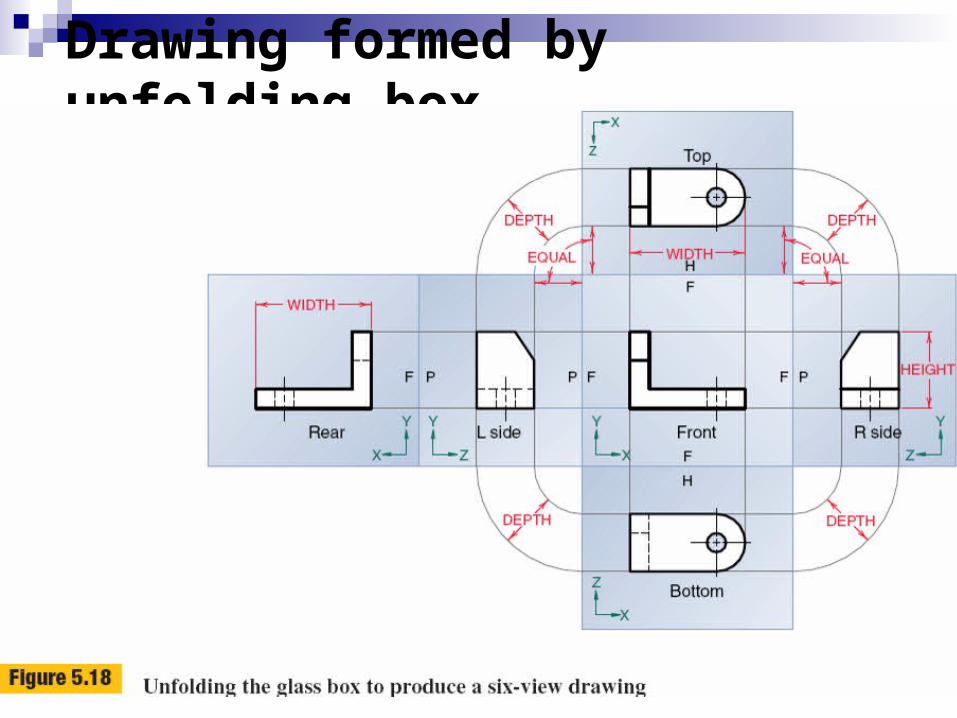
Drawing formed by unfolding box

Most Common Views
Top (or Plan) Front View (or Elevation) Right Side View (or Profile) Cross sections show interior of object –
later!
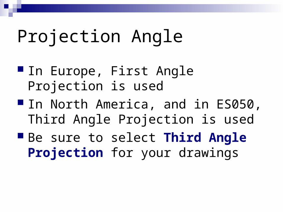
Projection Angle
In Europe, First Angle Projection is used In North America, and in ES050, Third
Angle Projection is used Be sure to select Third Angle Projection
for your drawings
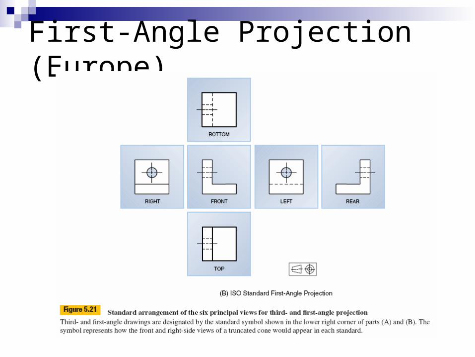
First-Angle Projection (Europe)
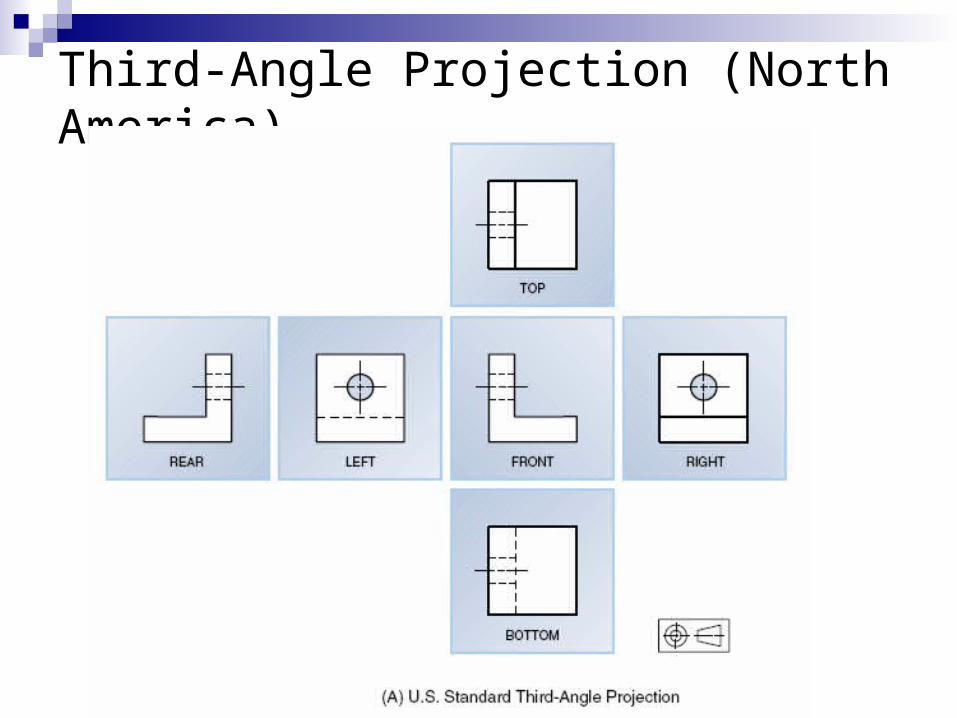
Third-Angle Projection (North America)
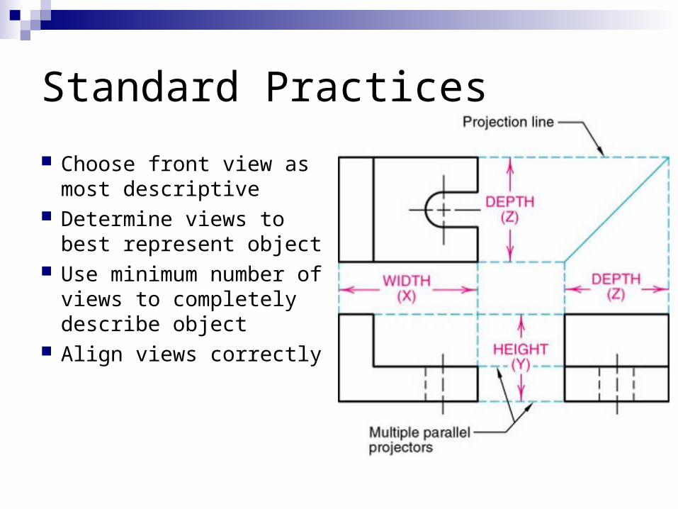
Standard Practices
Choose front view as most descriptive
Determine views to best represent object
Use minimum number of views to completely describe object
Align views correctly
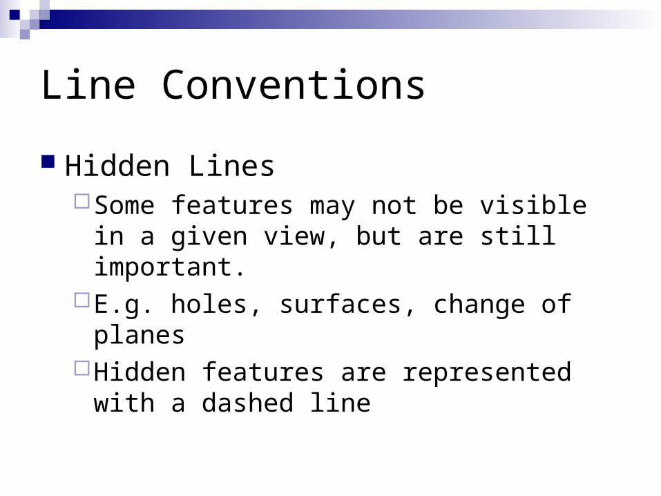
Line Conventions
Hidden LinesSome features may not be visible in a given
view, but are still important.E.g. holes, surfaces, change of planesHidden features are represented with a
dashed line

Hidden Lines
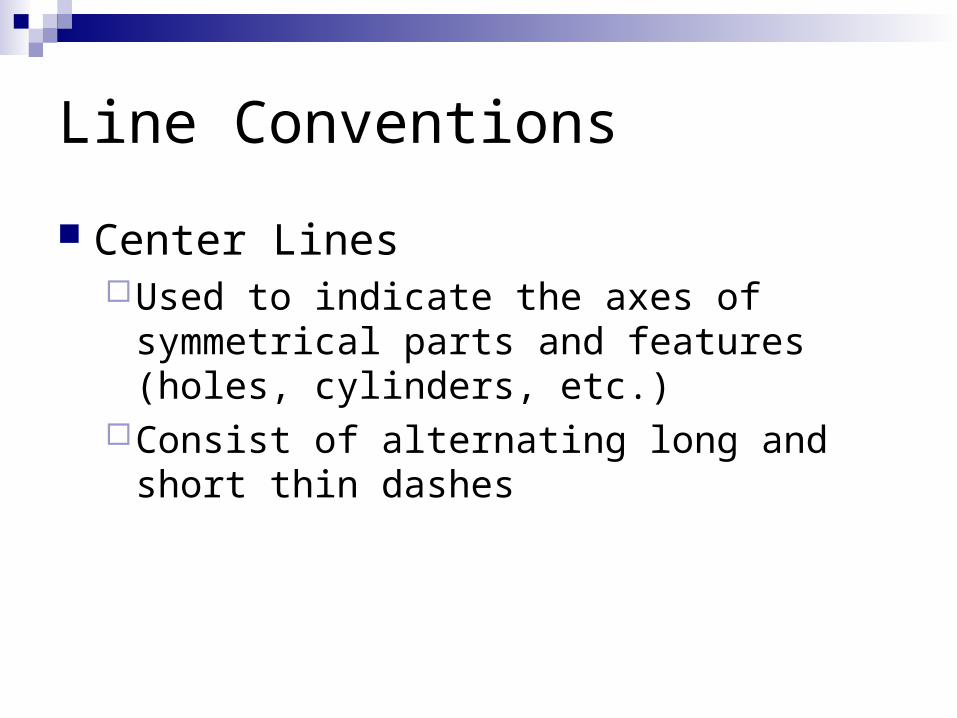
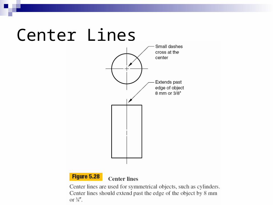
Line Conventions
Center LinesUsed to indicate the axes of symmetrical parts
and features (holes, cylinders, etc.)Consist of alternating long and short thin
dashes
Center Lines
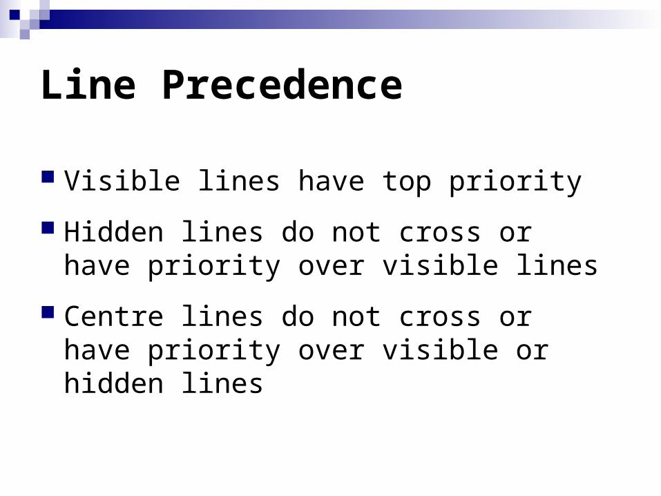
Line Precedence
Visible lines have top priority
Hidden lines do not cross or have priority over visible lines
Centre lines do not cross or have priority over visible or hidden lines
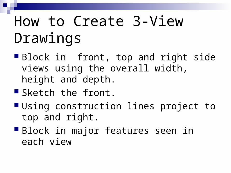
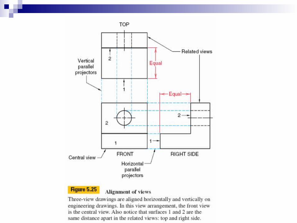
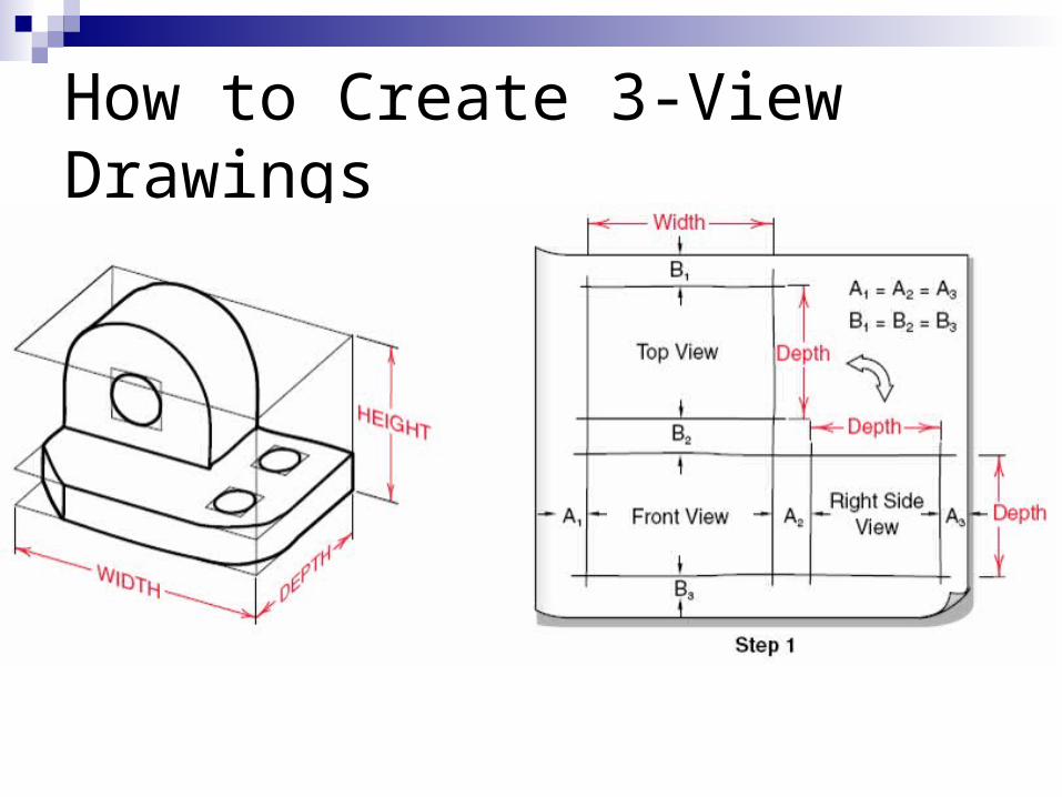
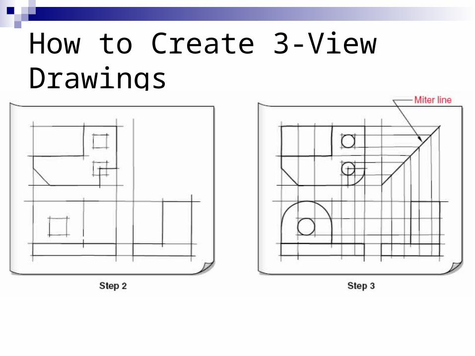
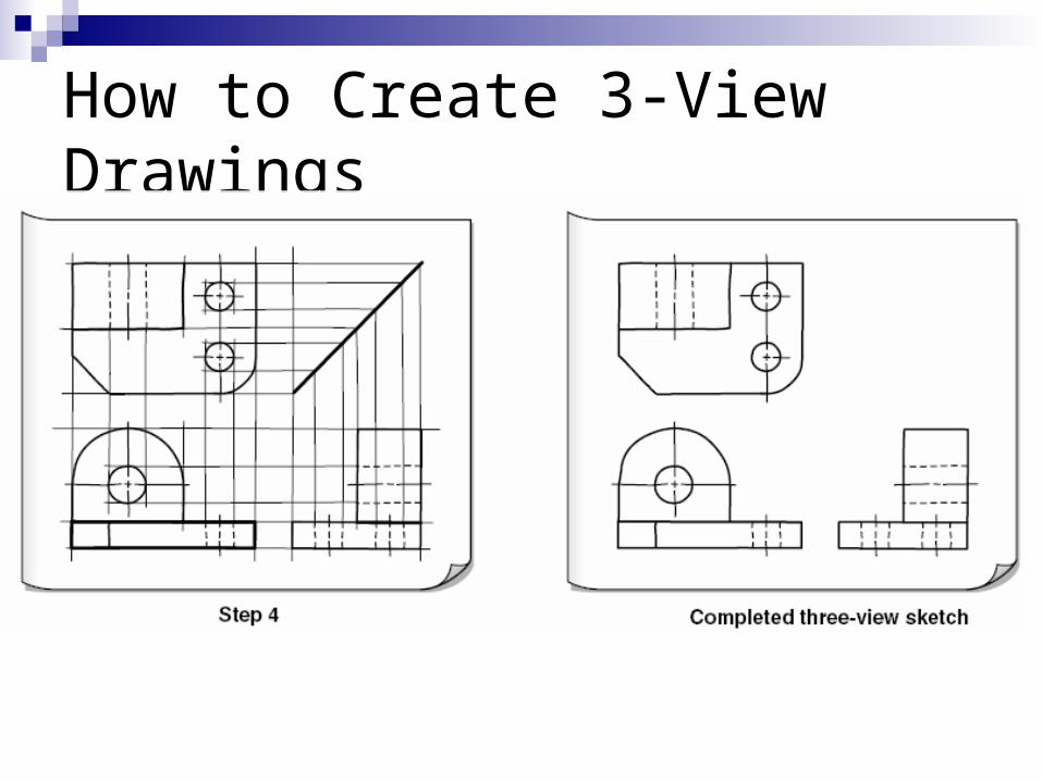
How to Create 3-View Drawings
Block in front, top and right side views using the overall width, height and depth.
Sketch the front. Using construction lines project to top and
right. Block in major features seen in each view
How to Create 3-View Drawings
How to Create 3-View Drawings
How to Create 3-View Drawings
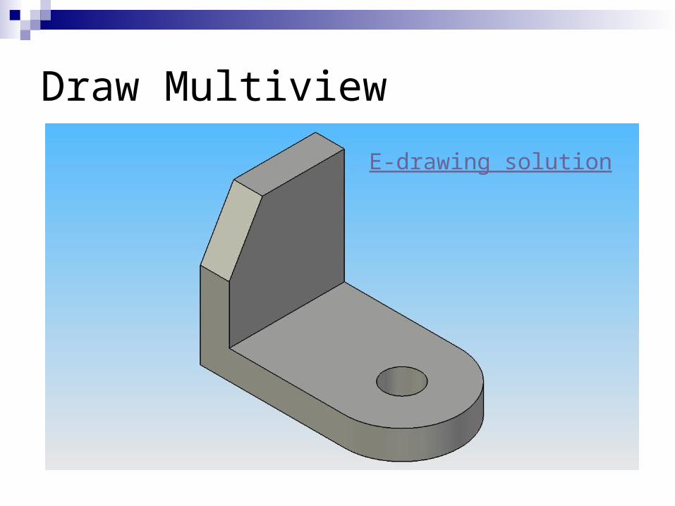
Draw Multiview
E-drawing solution
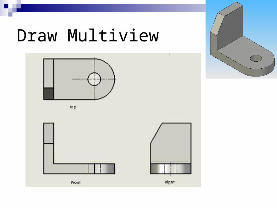
Draw Multiview
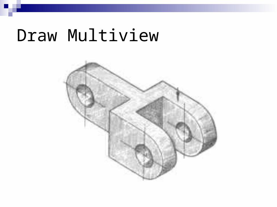
Draw Multiview
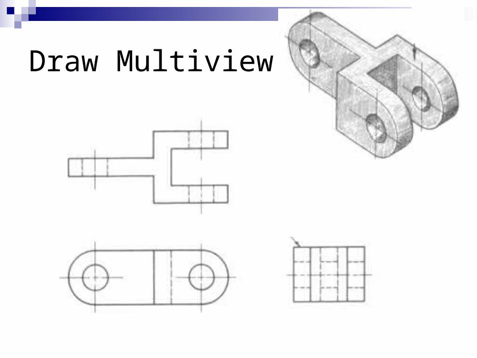
Draw Multiview