engineering failure analysis - upcommons · engineering failure analysis 23 (2012) 27–34 contents...
TRANSCRIPT

Engineering Failure Analysis 23 (2012) 27–34
Contents lists available at SciVerse ScienceDirect
Engineering Failure Analysis
journal homepage: www.elsevier .com/locate /engfai lanal
Failure investigation of a large pump-turbine runner
Eduard Egusquiza a,⇑, Carme Valero a, Xingxing Huang a, Esteve Jou a, Alfredo Guardo a,Cristian Rodriguez b
a Center Industrial Diagnostics, Universitat Politècnica de Catalunya (UPC), Av. Diagonal 647, 08028 Barcelona, Spainb Universidad de Concepción, Edmundo Larenas 270, Concepción, Chile
a r t i c l e i n f o
Article history:Received 17 March 2011Accepted 31 January 2012Available online 15 February 2012
Keywords:Turbine failuresVibrationImpeller failuresFatigue crackDynamic stress analysis
1350-6307/$ - see front matter � 2012 Elsevier Ltddoi:10.1016/j.engfailanal.2012.01.012
⇑ Corresponding author. Tel.: +34 93 4016714; faE-mail address: [email protected] (E. EgusqURL: http://www.upc.edu/cdif (E. Egusquiza).
a b s t r a c t
A failure investigation was conducted on a high-pressure machine with a large pump-tur-bine runner that was 2.9 m in diameter and had a maximum discharge rate of 32 m3/s.
A part of the runner broke off during operation. This released a piece of the crown, whichwent through the machine, causing further damage. An analysis of the broken runnerrevealed a fatigue problem, so the dynamic/vibratory behavior of the runner duringmachine operation was investigated to determine the cause.
First, the excitation forces acting on the runner during operation were studied. The mainexcitation in pump-turbines is generated by the interference between the rotating bladesand the stationary vanes, known as a rotor-stator interaction (RSI), which produces largepressure pulsations. The amplitude of the pressure pulsations was measured in the proto-type using pressure transducers.
Second, the modal response of the runner structure was analyzed. A finite element (FEM)model of the runner was developed and the main natural frequencies and associated modeshapes were identified.
A dynamic analysis was then performed to determine the runner response. A harmonicexcitation simulating the pressure pulsation of the RSI was applied to the numerical modelof the runner. The results showed a large stress concentration in the T-joint between theblade and crown where the crack originated. Finally, the possible causes of the damageare discussed.
� 2012 Elsevier Ltd. All rights reserved.
1. Introduction
Pump-turbines (PT) are high-head reversible machines that can be operated as a pump and as a turbine. They store energyby pumping water to the upper reservoir when there is surplus energy in the electrical network. This is due to low consump-tion (at night) or to the input from renewable power plants such as windmills. The stored water is turbined during the day atpeak hours when energy is needed.
The case reported here corresponds to a single-stage PT with a 400 m head and a maximum power of 110 MW. It is a ver-tical shaft machine with a hydraulic runner at the bottom and an electrical generator at the top. The runner has 7 blades, is2.9 m in diameter and is made of stainless steel. The distributor has 16 guide vanes. Fig. 1 shows a sketch of the machine andthe runner.
. All rights reserved.
x: +34 93 4015812.uiza).

Fig. 1. Sketch of the hydropower unit and runner.
28 E. Egusquiza et al. / Engineering Failure Analysis 23 (2012) 27–34
2. Damage description
A small crack was identified in the runner during a maintenance inspection. The runner was repaired and reinstalled. Afew months later, a part of the crown detached from the runner while the machine was in operation (see Fig. 2). The de-tached part passed through the machine, causing further damage.
Fig. 3 shows a close-up of the broken part of the runner. The analysis of the part revealed a fatigue problem. Beach markscan easily be identified in the crack, which was propagated from the T-joint between the runner blade and the crown.
Fig. 2. Sketch of the runner and distributor and a picture of the broken runner.
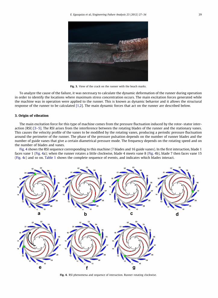
Fig. 3. View of the crack on the runner with the beach marks.
E. Egusquiza et al. / Engineering Failure Analysis 23 (2012) 27–34 29
To analyze the cause of the failure, it was necessary to calculate the dynamic deformation of the runner during operationin order to identify the locations where maximum stress concentration occurs. The main excitation forces generated whilethe machine was in operation were applied to the runner. This is known as dynamic behavior and it allows the structuralresponse of the runner to be calculated [1,2]. The main dynamic forces that act on the runner are described below.
3. Origin of vibration
The main excitation force for this type of machine comes from the pressure fluctuation induced by the rotor–stator inter-action (RSI) [3–5]. The RSI arises from the interference between the rotating blades of the runner and the stationary vanes.This causes the velocity profile of the vanes to be modified by the rotating vanes, producing a periodic pressure fluctuationaround the perimeter of the runner. The phase of the pressure pulsation depends on the number of runner blades and thenumber of guide vanes that give a certain diametrical pressure mode. The frequency depends on the rotating speed and onthe number of blades and vanes.
Fig. 4 shows the RSI sequence corresponding to this machine (7 blades and 16 guide vanes). In the first interaction, blade 1faces vane 1 (Fig. 4a); when the runner rotates a little clockwise, blade 4 meets vane 8 (Fig. 4b), blade 7 then faces vane 15(Fig. 4c) and so on. Table 1 shows the complete sequence of events, and indicates which blades interact.
Fig. 4. RSI phenomena and sequence of interaction. Runner rotating clockwise.

30 E. Egusquiza et al. / Engineering Failure Analysis 23 (2012) 27–34
The pressure pulsation generated by the RSI shows an almost regular sine-wave signal. From the rotating reference frame,any blade of the runner receives Zv pressure pulsations for each runner revolution (16 in this case). Thus, its frequency is:
fp ¼ nzv � fn ð1Þ
where fp is the pressure fluctuation frequency on the runner, Zv is the number of guide vanes and fn is the shaft rotating fre-quency. Each blade receives the same pressure pulsation but with a phase shift. For instance, when the pulsation in blade 1 isat a maximum, it is almost at a minimum in blades 3 and 6 (see Fig. 5).
The shape of the pressure pulsation generated by the RSI around the whole runner can be determined [3] by the followingequation:
mzg � k ¼ nzb ð2Þ
where n and m are integers, zg is the number of guide vanes, zb is the number of runner blades, and k is the diametrical mode.For this combination of blades and vanes (7/16), the main diametrical mode of the excitation is k = 2 rotating opposite therunner rotation. This means that at any instant there are two positive and two negative pressure pulses around the runner(see Fig. 6). This is a two-nodal diameter (2ND) excitation.
The amplitude of the pressure fluctuation depends on the head, the operating conditions and the design. It was measuredusing a pressure transducer located in the guide vane channel. Table 2 shows the resulting values.
In any dynamic problem, the worst conditions (maximum response of the structure) are found when there is a coinci-dence between the frequency of the excitation and a natural frequency of the structure with the same excitation mode shape.In this case, because the excitation has a 2ND mode shape, the maximum deformation of the runner will occur when the RSIexcitation frequency is near the natural frequency of the runner with a 2ND mode shape. Once the excitation characteristicsare determined, the dynamics of the runner are analyzed.
4. Dynamics of the runner structure
The finite element method (FEM) was used for the numerical simulation of the structural dynamics. The material param-eters were specified according to the actual values, as shown in Table 3.
Given the previous experience with the sensitivity of the element shape, the mesh density and the effects of the addedmass of water [6–9], the runner was modeled with 680,772 elements and 856,551 nodes. To consider the effect of the water,the runner was surrounded by the fluid domain. The fluid mesh was built by extending the structure mesh so that the nodeson the interface could be shared by both domains. The final fluid mesh contains 19,04,774 elements and 301,098 nodes. Fig. 7shows the runner mesh.
This model was used to perform the modal analysis and to calculate the natural frequencies and mode shapes of therunner.
Fig. 8 shows the results of the modal analysis. The first natural frequencies correspond to a zero-nodal diameter (0ND), aone-nodal diameter (1ND) and a two-nodal diameter (2ND) mode-shape. The natural frequency of interest (2ND) has a fre-quency of 186 Hz [10].
The mode shapes of the runner crown are somewhat similar to the ones of a disk but they are much more complex. Be-cause the stiffness in the runner is not uniform, the deformation varies greatly. The main deformation in all modes occurs in
Fig. 5. Pressure pulsation on each blade of the runner.

Table 1RSI characteristics.
Runner Stator Interaction
Sequence, e 1 2 3 4 5 6 7 8Runner blade number, R 1 4 7 3 6 2 5 1Stator vane number 1 8 15 6 13 4 11 2
Fig. 6. Distribution of pressure on the runner due to the RSI.
Table 2Pressure values of RSI measured with machine in operation.
Operating condition Tested load/maximum load (%) Static pressure Ps (MPa) Fluctuation amplitude P0 (MPa)
Turbine 40 3.40 0.3070 3.50 0.20
100 3.73 0.15
Table 3Properties of the material used.
Properties Value
Young’s modulus 205 GpaDensity 7700 kg/m3
Poisson’s ratio 0.30
Fig. 7. Runner mesh with surrounding water.
E. Egusquiza et al. / Engineering Failure Analysis 23 (2012) 27–34 31
the outlet diameter, as shown in Fig. 8, especially in the crown and band near the suction side of the blades, which remainalmost non-deformed. The displacement on the crown is greater than that on the band. This is the exact position where dam-ages are expected to happen on this type of runner.
5. Dynamic behavior
Given the excitation characteristics and the numerical model of the runner in water, the dynamic behavior was deter-mined by means of harmonic response analysis. To determine the response of the structure, a simple sine wave at a fre-quency value of fp was applied to each blade and the amplitude was obtained experimentally.

Fig. 8. Mode-shapes of the runner.
32 E. Egusquiza et al. / Engineering Failure Analysis 23 (2012) 27–34
Thus, the excitation force applied to the blade R(j) can be described in harmonic form as:
Pe;j ¼ P0 cosð2pfpðtÞ þ /e;jÞ ð3Þ
where P0 represents the amplitude of the dynamic component, and /e;j is the phase of the excitation force on blade R(j)
/e;j ¼ �2p7� ðe� 1Þ; e ¼ 1;2; . . . ;7 ð4Þ
For instance, the excitation exerted on blade R(3) is the fourth one in sequence shown in Table 1, where e is equal to 4.Hence, the phase value can be calculated as:
/4;3 ¼ �2p7� ð4� 1Þ ¼ �6p
7ð5Þ
and the excitation force can be expressed as:
Fig. 9. Dynamic model. The pressure pulsation is applied to each blade but with a phase shift.

Fig. 10. Distribution of equivalent stress on the runner.
E. Egusquiza et al. / Engineering Failure Analysis 23 (2012) 27–34 33
P4;3 ¼ P0 cos 320pðtÞ þ 67p
� �ð6Þ
All excitation parameters can be determined in this manner. Here, P0 is taken from Table 2 and the frequency is 160 Hz.Fig. 9 shows a sketch of the dynamic model. In the numerical model of the runner, the pressure pulsations described aboveare applied with their corresponding phase. For instance, blade 1 shows excitation P1,1, blade 2 shows excitation P6,2 with thesame characteristics but a different phase, and so on (see Fig. 5). This numerical model can be used to calculate the runnerresponse.
Fig. 10 shows the result of the computation and the deformation of the runner at an instant of time. Thus, the maximumdeformation occurs in the crown, in the external diameter of the impeller close to the blade.
An analysis of the whole deformation of the runner reveals a clear 2ND mode, with two nodal diameters between thedeformations.
A strength analysis is required to determine the distribution of the stress concentrations in the runner. As the fillets at theconnections between the crown, blades and band are not modeled to avoid an excessive number of elements, an absolutefigure of the stress level in these local areas cannot be determined with this mesh configuration. However, the general stressdistribution can be calculated and used to illustrate the stress level and distribution on the runner body.
The dynamic model indicates that the maximum stress concentration is located at the inlet of the flow passage in the T-joint between the crown and blade (see Fig. 10). This is where the first cracks appeared in the runner. A solution can be foundonce the critical location has been identified.
Because no resonance has been detected, a simple way of eliminating further problems in the runner is to reduce thestress level where the maximum stresses are identified. This can be done by increasing the radius of the T-joint fillets.
6. Conclusions
A small part of a large pump-turbine runner broke off during operation. The analysis of the broken runner revealed fatiguedamage. The failure was analyzed by simulating the dynamic behavior of the runner that caused the deformations and stres-ses under operating conditions.
The response of the structure depends on the mode shape of the excitation and on the mode shape of the natural fre-quency excited. If the mode shape is different, the response is small; if the mode shape is the same, the response is very high.
The dynamic analysis showed the largest concentration of stresses in the periphery of the runner where the blades andthe crown are connected. This means that this part was more prone to suffer fatigue damage.
The vibrations and deformations in this runner were high especially for the following reasons: first, because the pressurepulsation generated by the runner stator interaction was very high due to the characteristics of the machine (high head,small gap, large blade load); second, because the maximum deformation in this type of runner occurs in the tip diameterat the connection between the runner blades and the crown, where the action of the pressure pulsations is generated duringoperation; and third, although no resonance was detected, the natural frequency of the runner with a 2ND is not too far fromthe excitation frequency (also with a 2ND mode shape), which enhances the response.
A deficient finishing of the fillets after the repair was considered to be the cause of the damage. The problem was solvedby increasing the radius of the T-joint and ensuring an accurate construction of the fillets.
Acknowledgment
The authors wish to acknowledge the financial aid provided by the Spanish Ministry of Science and Technology (Grant No.DPI2009-12827).

34 E. Egusquiza et al. / Engineering Failure Analysis 23 (2012) 27–34
References
[1] Lais S, Liang Q, et al. Dynamic analysis of francis runners – experiment and numerical simulation. Int J Fluid Machinery Syst 2009;2(4):303–14.[2] Seidel U, Grosse G. New approaches to simulate the dynamic behaviour and dynamic stresses of Francis – and pump turbine runners. IAHR int meeting
of WG on cavitation and dynamic problems in hydraulic machinery and systems. Barcelona, Spain, 28–30 June 2006.[3] Tanaka H. Vibration behaviour and dynamic stress of runners of very high head reversible pump-turbines. IAHR Symposium Belgrade; 1990.[4] Mateos Borja, Egusquiza Eduard, Escaler Xavier. Analysis of runner stator interaction in operating pump-turbines. In: IAHR symposium proceedings of
the hydraulic machinery and systems 21st IAHR symposium September 9–12, 2002, Lausanne.[5] Rodriguez CG, Egusquiza E, Santos I. Frequencies in the vibration induced by the rotor stator interaction in a centrifugal pump turbine. J Fluids Eng
2007;129:1428–35 [ASME ISSN: 0098-2202].[6] Liang QW, Rodriguez CG, Egusquiza E, Escaler X, Farhat M, Avellan F. Numerical simulation of fluid added mass effect on a francis turbine runner.
Comput Fluids 2006;36(6):1106–18 [ISSN: 0045-7930].[7] Rodriguez CG, Egusquiza E, Escaler X, Liang QW, Avellan F. Experimental investigation of added mass effects on a Francis turbine runner in still water. J
Fluids Struct 2006;22(5):699–712 [ISSN: 0889-9746].[8] Escaler X, Liang QW, Valero C, Egusquiza E, Lais S, Sick M, et al. In: Experimental modal analysis of a francis model runner 24th IAHR symposium on
hydraulic machinery and systems. October 27–31, 2008. (Foz do Iguassu, BRASIL).[9] Valero C, Egusquiza E, Liang Q, Escaler X, Coussirat M. Constraint effects on natural frequencies in hydraulic turbine runners. In: 24th IAHR symposium
on hydraulic machinery and systems. October 27–31, 2008. (Foz do Iguassu, BRASIL).[10] Liang Q. Dynamic behavior of hydraulic turbine runners. PhD Thesis UPC Barcelona; June 2008.