engineering design code specification d1
TRANSCRIPT
GEOMETRIC ROAD DESIGN
Amended September 2016 Armidale Regional Council D1 - 1
ENGINEERING DESIGN CODE
SPECIFICATION D1
GEOMETRIC ROAD DESIGN
(Urban and Rural)
GEOMETRIC ROAD DESIGN
Amended September 2016 Armidale Regional Council D1-2
Amendment Record for this Specification Part
This Specification is the Armidale Regional Council version of the AUS-SPEC generic specification D1 and includes Council’s primary amendments to the specification.
Details are provided below outlining the clauses amended from the Council edition of this AUS-SPEC Specification Part D1. The clause numbering and context of each clause are preserved. New clauses are added towards the rear of the specification part as special requirements clauses. Project specific additional script is shown in the specification as italic font.
The amendment code indicated below is ‘A’ for additional script ‘M’ for modification to script and ‘O’ for omission of script. An additional code ‘P’ is included when the amendment is project specific.
Amendment
Sequence No.
Key Topic addressed in amendment Clause
No.
Amendment
Code
Author
Initials
Amendment
Date
1 Major Revision of specifications for adoption by Armidale Regional Council
All AMO SPM 25/05/16
2 Hammerhead option for end of road removed D1.30 Fig D1.8
O SPM 31/8/16
3 Re-introduce salinity in soil paragraphs 8 & 9 D1.7 A SPM 31/8/16
4 Remove reference to Armidale Regional Council Traffic Advisory Committee (TAC)
D1.17(3) D1.18(1) D1.19(1)
O SPM 31/8/16
5 Battle axe handles to serve no more than 1 lot or 1 dwelling
D1.33 T D1.8
A SPM 31/8/16
6 Additions and modifications to road standards tables
T D1.4 T D1.5 T D1.6
AMO SPM 20/9/16
7 Addition of industrial road intersection kerb return radius
T D1.19 A SPM 19/10/16
GEOMETRIC ROAD DESIGN
Amended September 2016 Armidale Regional Council D1-3
CONTENTS CLAUSE PAGE
CONTENTS ........................................................................................................................... 3
GENERAL ............................................................................................................................. 5
D1.01 SCOPE .................................................................................................................................................... 5
D1.02 AIMS ........................................................................................................................................................ 5
D1.03 REFERENCE AND SOURCE DOCUMENTS ......................................................................................... 6
D1.04 CONSULTATION .................................................................................................................................... 7
D1.05 PLANNING CONCEPTS ......................................................................................................................... 7
D1.06 DRAWING REQUIREMENTS ................................................................................................................. 8
URBAN DESIGN CRITERIA ................................................................................................. 9
D1.07 ROAD HIERARCHY ................................................................................................................................ 9
D1.08 ROAD NETWORK ................................................................................................................................. 12
D1.09 DESIGN SPEED .................................................................................................................................... 13
D1.10 LONGITUDINAL GRADIENT (Refer Austroads Design Guides) .......................................................... 14
D1.11 HORIZONTAL CURVES AND TANGENT LENGTHS (Refer Austroads Design Guides) .................... 15
D1.12 VERTICAL CURVES (Refer Austroads Design Guides) ....................................................................... 16
D1.13 SUPERELEVATION (Refer Austroads Design Guides) ........................................................................ 16
D1.14 ROAD RESERVE CHARACTERISTICS ............................................................................................... 17
D1.15 CROSSFALL ......................................................................................................................................... 18
D1.16 VERGES AND PROPERTY ACCESS (Refer Driveway Policy – POL 035) .......................................... 18
D1.17 INTERSECTIONS.................................................................................................................................. 19
D1.18 ROUNDABOUTS ................................................................................................................................... 20
D1.19 TRAFFIC CALMING .............................................................................................................................. 21
D1.20 PARKING ............................................................................................................................................... 23
D1.21 BUS ROUTES ....................................................................................................................................... 23
GEOMETRIC ROAD DESIGN
Amended September 2016 Armidale Regional Council D1-4
RURAL DESIGN CRITERIA (Refer Austroads Design Guides) ...................................... 24
D1.22 GENERAL .............................................................................................................................................. 24
D1.23 SIGHT DISTANCES .............................................................................................................................. 24
D1.24 HORIZONTAL AND VERTICAL ALIGNMENT ...................................................................................... 24
D1.25 INTERSECTIONS.................................................................................................................................. 25
D1.26 PLAN TRANSITIONS ............................................................................................................................ 25
D1.27 CHARACTERISTICS OF RURAL ROADS ............................................................................................ 30
D1.29 SCOUR PROTECTION ......................................................................................................................... 30
SPECIAL REQUIREMENTS ............................................................................................................................... 34
D1.30 TURNING AREAS ................................................................................................................................. 34
D1.31 INDUSTRIAL ROAD WIDTHS .............................................................................................................. 34
D1.32 CUL-DE-SAC DIMENSIONS ................................................................................................................. 34
D1.33 BATTLE AXE HANDLES ....................................................................................................................... 34
D1.34 KERB RETURN DESIGN RADII ............................................................................................................ 35
D1.35 GUIDE POSTS ...................................................................................................................................... 36
D1.36 BATTER SLOPES ................................................................................................................................. 36
D1.37 INTERNAL DRIVEWAYS ...................................................................................................................... 37
D1.38 PRIVATE ACCESSWAYS .................................................................................................................... 37
D1.39 PUBLIC ROAD LIGHTING .................................................................................................................... 38
D1.40 LINEMARKING...................................................................................................................................... 39
D1.41 SIGNS .................................................................................................................................................... 39
D1.42 SHOULDERS ........................................................................................................................................ 39
D1.43 ROADSIDE DRAINAGE ........................................................................................................................ 40
D1.44 KERB AND GUTTER............................................................................................................................. 41
D1.45 RESERVED ........................................................................................................................................... 42
D1.46 RESERVED ........................................................................................................................................... 42
GEOMETRIC ROAD DESIGN
Amended September 2016 Armidale Regional Council D1-5
DESIGN SPECIFICATION D1
GEOMETRIC ROAD DESIGN (Urban and Rural)
GENERAL
D1.01 SCOPE
1. This section sets out the specifications developed specifically for the design of subdivision, public and private (driveway) roadworks using principles of street design to ensure safety and improved amenity and to reduce pedestrian/vehicular conflicts.
Subdivision Roadworks
2. A fundamental requirement of the design process is for designers to determine the vehicle speed which is deemed acceptable for a particular subdivision or section of road. The concept of designing to regulatory street speeds is contrary to the current principles of subdivision road design.
Acceptable Vehicle Speed
3. All relevant design principles must be integrated in the development of the road network. A careful balance is required between maximising amenity, safety and convenience considerations and those related to the drivers’ perception of driving practice.
Integrated Design Principles
4. The words “street” and “road” are interchangeable throughout all parts of this Specification.
5. For the purpose of this Specification the definition of terms used to define the components of the road reserve shall be in accordance with AS 1348.1 and AMCORD.
Road Reserve Component Definitions
AS 1348.1 terms:
Carriageway - That portion of the road or bridge devoted particularly to the use of vehicles, inclusive of shoulders and auxiliary lanes.
Footpath - The paved section of a pathway (verge).
Pathway - A public way reserved for the movement of pedestrians and of manually propelled vehicles (AMCORD verge).
Pavement - That portion of a carriageway placed above the subgrade for the support of, and to form a running surface for, vehicular traffic.
Shoulder - The portion of the carriageway beyond the traffic lanes and contiguous and flush with the surface of the pavement.
AMCORD term:
Verge: - That part of the road reserve between the carriageway and the road reserve boundary. It may accommodate public utilities, footpaths, stormwater flows, street lighting poles and plantings.
D1.02 AIMS
1. The provision of a road system within a subdivision is to be designed so as to achieve the following aims:
Provide convenient and safe access to all allotments for pedestrians, vehicles and cyclists.
GEOMETRIC ROAD DESIGN
Amended September 2016 Armidale Regional Council D1-6
Provide safe, logical and hierarchical transport linkages with existing street system.
Provide appropriate access for buses, emergency and service vehicles.
Provide for a quality product that minimises maintenance costs.
Provide a convenient way for public utilities.
Provide an opportunity for street landscaping.
Provide convenient parking for visitors.
Have appropriate regard for the climate, geology and topography of the area.
D1.03 REFERENCE AND SOURCE DOCUMENTS
(a) Council Documents Local Environmental Plan (LEP) - current Development Control Plan - current All Specifications for Design and Construction..
(b) Australian Standards AS 1348.1 - Road and traffic engineering – Glossary of terms, Road
design and construction. AS 1428 - Design For Access and Mobility. AS 2890 - Parking facilities - all parts. AS 1158 - Road Lighting - all parts. AS 3845 - Road Safety Barrier Systems. SAA HB69.14 - Guide to traffic engineering practice - Bicycles. AS/NZS 3845 - Road safety barrier systems. AS1100.401 - Technical Drawing Engineering Survey and Engineering
Survey Design
(c) State Authorities Roads and Maritime Services (RMS) NSW - Road Design Guide (formerly RTA).
- Guide to Traffic Generating Developments Department of Housing - Road Manual, 1987. Department of Urban Affairs (formerly Environment) and Planning - Technical Bulletin 12
(1981), Residential Road Widths. NSW Police – Safer By Design
(d) Other AUSTROADS Guide to Road Design (AGRD) - all parts
Guide to Road Safety (AGRS) - all parts Guide to Road Transport Planning (AGRTP) Cycling Aspects Of Austroads Guides Guide to Traffic Management (AGTM) - all parts RMS amendments to Austroads Guidelines - RMS website
The Institute of Municipal Engineering Australia, Qld Division - 1993: Design Guidelines for Subdivisional Street works.
GEOMETRIC ROAD DESIGN
Amended September 2016 Armidale Regional Council D1-7
ARRB Special Report No. 33, L E Comerford: A Review of Subdivision Road Design Criteria.
Commonwealth Department of Housing and Regional Development – 1995: Australian Model Code for Residential Development. (AMCORD). A National Resource Document for Residential Development.
Stapleton, C 1984: Streets Where We Live – A Manual for the Design of Safer Residential Estates.
Stapleton, C 1988, Dept of Transport South Australia: Planning & Road Design for New Residential Subdivisions.
Brindle, R 1988, ARRB: Planning & Design of the Local Distributor.
Colman, J 1978, ARRB: Streets for Living.
Pak-Poy Kneebone – 1989: Research Study into Road Characteristics for Residential Development.
D1.04 CONSULTATION
1. Designers are encouraged to consult with the Council and other relevant authorities prior to or during the preparation of design. Designers should, in addition to requirements of this Specification, ascertain specific requirements of these authorities as they relate to the designs in hand.
Council, Other Authorities
2. Public consultation on designs shall be provided where such action is required by Council’s current policy.
Public Consultation
3. The Designer shall obtain service plans from all relevant public utility authorities and organisations whose services may exist within the area of the proposed development. These services are to be plotted on the relevant drawings including the plan and cross-sectional views.
Public Utilities
D1.05 PLANNING CONCEPTS
1. In new areas (as distinct from established areas with a pre-existing road pattern) each class of route should reflect its role in the road hierarchy by its visual appearance and related physical design standards. Routes should differ in alignment and design standard according to the volume of traffic they are intended to carry, the desirable traffic speed, and other factors.
Road Hierarchy
2. The road pattern and width must be in conformity with that shown on any relevant Development Control Plan. In areas not covered by these plans, the pattern and width(s) will be determined by Council on their merits.
Conformance with DCP
3. The road network for residential developments should have clear legibility. Legibility
4. The road network should reinforce legibility by providing sufficient differentiation between the road functions.
Differentiation
5. Distinct landmark features such as watercourses, mature vegetation or ridge lines should be emphasised within the structural layout so as to enhance the legibility.
Landmark Features
6. Whilst legibility can be enhanced by introduced physical features such as pavement and lighting details, the road network should by its inherent design and functional distinction provide the necessary legibility.
Introduced Features
GEOMETRIC ROAD DESIGN
Amended September 2016 Armidale Regional Council D1-8
7. The maximum number of turning movements at intersections or junctions that a driver should be required to undertake to reach a particular address within the development should be minimised.
Intersection Turning Movements
8. There will be special constraints and costs associated with the design of roads through or adjacent to land known to be salt affected. Early planning shall consider avoiding detrimental interference with land known to be salt affected. Adjustments in horizontal and vertical line shall be considered to avoid recharge of subsurface water within or adjacent to the road reserve. Consultation with the relevant land and water resource authority shall be mandatory under the above circumstances.
Salinity Prevention, Early Planning, Mandatory Consultation
9. Appropriate native deep-rooted species should be selected for plantings in association with road reserve works. Plantations should be of sufficient size and density, multiple row belts and relatively close spacings are recommended, to be effective in their desired role of lowering the groundwater table.
Landscaping, Salinity Prevention
D1.06 DRAWING REQUIREMENTS
(a) Preferred Reduction Ratios
1. In general, all plans for urban design are to be reduced to 1:500. Rural designs may be reduced to 1:1000. In circumstances where very short sections of road are encountered in design, plans may be reduced to a scale of 1:200.
Urban Rural
Longitudinal Sections 1:500 H 1:50V
1:1000 H 1:100V
Cross Sections 1:100 Natural 1:200 Natural where large
1: 100 Natural 1:200 Natural where large
Intersections 1:200 and Contoured 1: 200 and Contoured
Cross section intervals Every 10 to 20m Every 20 to 50m
(b) Drawing Sheets
1. Separate sheets should be provided for but are not limited to: a. Cover sheets b. Plan views c. Longitudinal sections d. Cross sections e. Structural details where applicable
f. Standard drawings (referenced but not necessary to reproduce as hard copy) g. Erosion and sediment control plan
(c) Drawing Presentation
1. Drawings are to be presented on A3 sheets unless otherwise authorised. They are to be clear and legible and prepared in consistent lettering and style and shall be in accordance with AS1100.401. Council has the authority to refuse drawings that do not meet these drafting requirements. Drawings copied from other works will not be accepted. All drawings shall be clearly referenced with notations and tables as appropriate. The Designer should always be mindful that apart from being a permanent record and legal document, drawings should be easily read and understood by the Contractor, and others involved in the construction of the Works. Terminology should be kept in 'plain English' where possible.
Clear and Legible, Permanent Record, Legal Document
2. The scope and sequence of drawing sheets shall comply with the example provided in Annexure DQS-B of the Specification for QUALITY ASSURANCE REQUIREMENTS FOR DESIGN.
Compliance
GEOMETRIC ROAD DESIGN
Amended September 2016 Armidale Regional Council D1-9
(d) Certification
1. Drawings shall bear the signature of the design consultant and shall, where required by the Council, be certified as complying with the appropriate design specifications (D1 to D12). The certificate shall be in the format detailed in Annexure DQS-A of the Specification for QUALITY ASSURANCE REQUIREMENTS FOR DESIGN.
Design Consultant
(e) Certification
1. All design drawings shall reflect the road chainages used by Council on designs for existing roads.
Council Road Chainages
URBAN DESIGN CRITERIA
D1.07 ROAD HIERARCHY
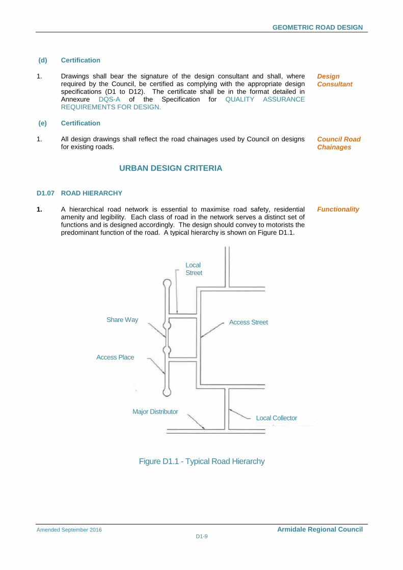
1. A hierarchical road network is essential to maximise road safety, residential amenity and legibility. Each class of road in the network serves a distinct set of functions and is designed accordingly. The design should convey to motorists the predominant function of the road. A typical hierarchy is shown on Figure D1.1.
Functionality
Figure D1.1 - Typical Road Hierarchy
Access Street
Access Place
Share Way
Local Street
Local Collector Major Distributor
GEOMETRIC ROAD DESIGN
Amended September 2016 Armidale Regional Council D1-10
2. The levels of roads are (Refer DCP 2012 S3, Ch3.1, Table 2) : Share way – As approved by Council, refer NSW Police Safer By Design
Access Place / Cul-de-sac Minor Access or Local Street
Access Street Local Collector Minor or Major Distributor
Emergency Access
Provide at least two emergency access routes for each street type in all subdivisions.
Traffic calming Provide calming geometry to conform with Austroads Design Guides.
Share way (As approved by Council) A minor street which carries the lowest volume of traffic, providing driveway access to no more than 3 lots on each side and forming a link between two access places. Vehicles, pedestrians and recreation uses are shared, with design to encourage priority for pedestrians.
Road Hierarchy
Emergency Access
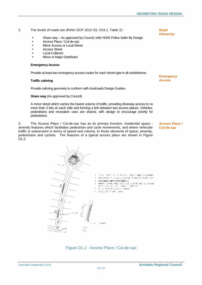
3. The Access Place / Cul-de-sac has as its primary function, residential space - amenity features which facilitates pedestrian and cycle movements, and where vehicular traffic is subservient in terms of speed and volume, to those elements of space, amenity, pedestrians and cyclists. The features of a typical access place are shown in Figure D1.2.
Access Place / Cul-de-sac
Figure D1.2 - Access Place / Cul-de-sac
GEOMETRIC ROAD DESIGN
Amended September 2016 Armidale Regional Council D1-11
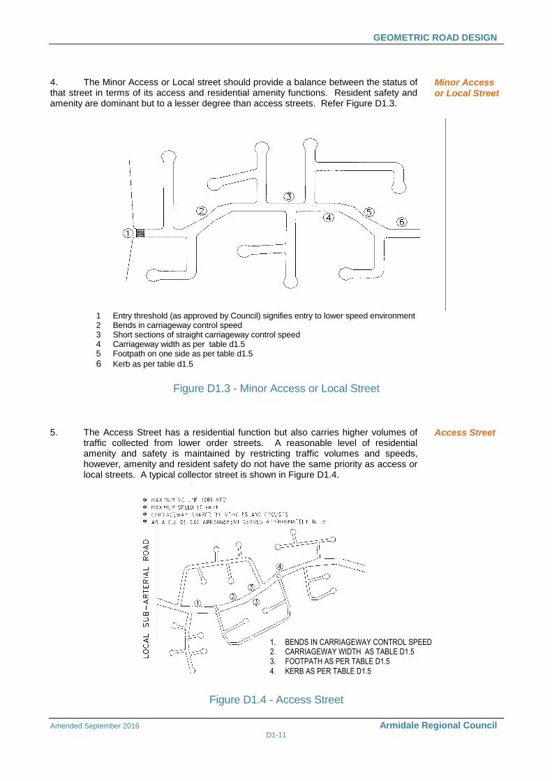
4. The Minor Access or Local street should provide a balance between the status of that street in terms of its access and residential amenity functions. Resident safety and amenity are dominant but to a lesser degree than access streets. Refer Figure D1.3.
Minor Access or Local Street
1 Entry threshold (as approved by Council) signifies entry to lower speed environment 2 Bends in carriageway control speed 3 Short sections of straight carriageway control speed 4 Carriageway width as per table d1.5 5 Footpath on one side as per table d1.5
6 Kerb as per table d1.5
Figure D1.3 - Minor Access or Local Street
5. The Access Street has a residential function but also carries higher volumes of traffic collected from lower order streets. A reasonable level of residential amenity and safety is maintained by restricting traffic volumes and speeds, however, amenity and resident safety do not have the same priority as access or local streets. A typical collector street is shown in Figure D1.4.
Access Street
1. BENDS IN CARRIAGEWAY CONTROL SPEED2. CARRIAGEWAY WIDTH AS TABLE D1.53. FOOTPATH AS PER TABLE D1.5
4. KERB AS PER TABLE D1.5
Figure D1.4 - Access Street
GEOMETRIC ROAD DESIGN
Amended September 2016 Armidale Regional Council D1-12
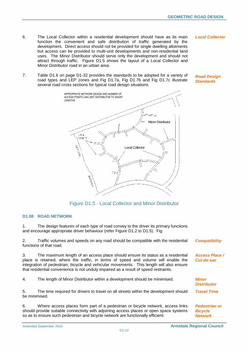
6. The Local Collector within a residential development should have as its main function the convenient and safe distribution of traffic generated by the development. Direct access should not be provided for single dwelling allotments but access can be provided to multi-unit developments and non-residential land uses. The Minor Distributor should serve only the development and should not attract through traffic. Figure D1.5 shows the layout of a Local Collector and Minor Distributor road in an urban area.
7. Table D1.6 on page D1-32 provides the standards to be adopted for a variety of road types and LEP zones and Fig D1.7a, Fig D1.7b and Fig D1.7c illustrate several road cross sections for typical road design situations.
Local Collector
Road Design Standards
APPROPRIATE NETWORK DESIGN AND NUMBER OFACCESS POINTS CAN LIMIT DISTRIBUTOR TO SHORT
LENGTHS
DISTRIBUTOR
ROAD
Figure D1.5 - Local Collector and Minor Distributor
D1.08 ROAD NETWORK
1. The design features of each type of road convey to the driver its primary functions and encourage appropriate driver behaviour (refer Figure D1.2 to D1.5). Fig
2. Traffic volumes and speeds on any road should be compatible with the residential functions of that road.
Compatibility
3. The maximum length of an access place should ensure its status as a residential place is retained, where the traffic, in terms of speed and volume will enable the integration of pedestrian, bicycle and vehicular movements. This length will also ensure that residential convenience is not unduly impaired as a result of speed restraints.
Access Place / Cul-de-sac
4. The length of Minor Distributor within a development should be minimised. Minor Distributor
5. The time required for drivers to travel on all streets within the development should be minimised.
Travel Time
6. Where access places form part of a pedestrian or bicycle network, access links should provide suitable connectivity with adjoining access places or open space systems so as to ensure such pedestrian and bicycle network are functionally efficient.
Pedestrian or Bicycle Network
Local Collector
Minor Distributor
GEOMETRIC ROAD DESIGN
Amended September 2016 Armidale Regional Council D1-13
7. The road network should ensure that no road links with another road which is more than two levels higher or lower in the hierarchy. In exceptional circumstances roads may link with others that are more than two levels apart, however, no access place or local street should have access to an access-controlled Major Distributor road.
Road Links
8. Connections between internal roads should be T-junctions or controlled by roundabouts. The spacing of T- junctions shall be in accordance with Chapter 7 of Austroads Guide to Road Design Part 4A: Unsignalised Intersections.
Internal Road Connections
9. The road layout should conform to the requirements of the external road network and satisfy the transport provisions of an outline development plan.
Transport Provisions
10. The external road network should be designed and located to provide routes which are more convenient for potential through traffic within the network. Major roads should be provided at intervals of no more than 1.5 km and should be complete and of adequate capacity to accommodate through network movements. The internal road system should not provide through routes that are more convenient than the external road network.
11. Subdivision and development proposals are to show the proposed hierarchy on the design drawings as well as in the Traffic Impact Study. When preparing a road hierarchy plan for a proposed subdivision or development, consideration shall be given to the function of the road network within the entire road network, the expected traffic volume and the connection with the adjacent road network.
12. The road category to be adopted and formation widths to be used for design purposes will be approved by Council following submission of a detailed analysis of the proposed site, the design traffic and the nature and function of the subdivision or development. The adopted road category and width shall apply to the entire length of the road, and progressive widening or narrowing of a road through intersections or development stages will not be permitted.
13. When calculating the proposed category or function of a road, designers must consider the ultimate number of lots serviced by the road when all potential stages of development and subdivision are complete. Consultation with Council regarding the ultimate function of the road may be necessary.
14. It is the designers’ responsibility to ensure that road reserve widths are sufficient to accommodate all road and ancillary services and utilities that are required to be located within the reserve. The road reserve may need to be wider than the minimum width required. Consultation with relevant service authorities, such as telecommunications (including NBN Co.) and electricity distribution authorities, to determine their requirements for the subdivision will be necessary. Refer standard drawing No 030-063 for guidance in the location of utility services.
External Road Network
Hierarchy & Traffic Impact Study
Adopted Road Category
Consultation
Utility Location Within Road Reserve
D1.09 DESIGN SPEED
1. Design speed is generally used as the basic parameter in the specification of design standards and in determining the minimum design value for other elements. NSW Roads and Maritime Services bases its current design standards on a travel speed rather than a design speed. Travel speed identifies a speed/horizontal radius relationship. This approach is intended for roads of a minimum travel speed of 60 km/h. The maximum speed limit in NSW for built-up areas is 50 km/h as the default speed limit and this should be used in calculating design values which depend on speed, (e.g. local collector and distributor roads) however, in difficult topography, the design speed may be reduced. Vehicular speeds are also limited by road intersections as well as changes in horizontal and vertical alignment.
RMS Guidelines
GEOMETRIC ROAD DESIGN
Amended September 2016 Armidale Regional Council D1-14
2. Adoption of a low design speed discourages speeding, however, where vertical or horizontal curves of low design speed are located in otherwise high speed sections the result is a potentially dangerous section of road. It should be recognised that in low standard roads, operating speeds will tend to be in excess of arbitrary speed standards. Attention should be given to ensuring that potentially hazardous features are visible to the driver and adopting traffic engineering measures which will help a driver avoid errors of judgement.
Low Speeds
Hazardous Features
3. Generally the following target speeds in urban streets should be adopted:
Access Place / Cul-de-sac 25 km/h Minor Access or Local Street 40 km/h Access Street 40 km/h Local Collector 50 km/h
Minor or Major Distributor 60/80 km/h
Generally the following target speeds in rural residential roads should be adopted:
Minor Access or Local Street 40 to 60 km/h Access Street 40 to 60 km/h Local Collector 60 to 80 km/h Minor or Major Distributor 80 to100km/h
Target Speeds
Urban Streets
Rural Residential Roads
4. The need for road safety barriers shall be assessed and designed in accordance with AS/NZS 3845.
Road Safety Barriers
D1.10 LONGITUDINAL GRADIENT (Refer Austroads Design Guides)
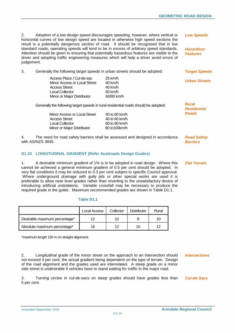
1. A desirable minimum gradient of 1% is to be adopted in road design. Where this cannot be achieved a general minimum gradient of 0.5 per cent should be adopted. In very flat conditions it may be reduced to 0.3 per cent subject to specific Council approval. Where underground drainage with gully pits or other special works are used it is preferable to allow near level grades rather than reverting to the unsatisfactory device of introducing artificial undulations. Variable crossfall may be necessary to produce the required grade in the gutter. Maximum recommended grades are shown in Table D1.1.
Flat Terrain
Table D1.1
Local Access Collector Distributor Rural
Desirable maximum percentage* 12 10 8 10
Absolute maximum percentage* 16 12 10 12
*maximum length 150 m on straight alignment.
2. Longitudinal grade of the minor street on the approach to an intersection should not exceed 4 per cent, the actual gradient being dependent on the type of terrain. Design of the road alignment and the grades used are interrelated. A steep grade on a minor side street is undesirable if vehicles have to stand waiting for traffic in the major road.
Intersections
3. Turning circles in cul-de-sacs on steep grades should have grades less than 5 per cent.
Cul-de-Sacs
GEOMETRIC ROAD DESIGN
Amended September 2016 Armidale Regional Council D1-15
D1.11 HORIZONTAL CURVES AND TANGENT LENGTHS (Refer Austroads Design
Guides)
1. The horizontal alignment of a road is normally in a series of tangents (straights) and curves which may be connected by transition curves. The choice of the horizontal alignment is normally determined from the design speeds for a particular street within the road hierarchy as described in Clause D1.09. Designers should ensure that, for a given design speed, the minimum radius of curvature utilised is such that drivers can safely negotiate the curve. Curves which progressively tighten produce an uncomfortable sense of disorientation and alarm. Sudden reverse curves which drivers cannot anticipate also have a potential to cause similar conditions.
Speed/Radius Relation
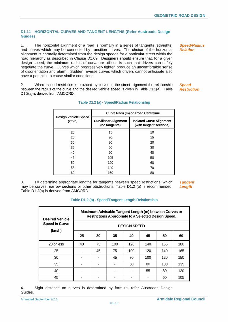
2. Where speed restriction is provided by curves in the street alignment the relationship between the radius of the curve and the desired vehicle speed is given in Table D1.2(a). Table D1.2(a) is derived from AMCORD.
Speed Restriction
Table D1.2 (a) - Speed/Radius Relationship
Design Vehicle Speed
(km/h)
Curve Radii (m) on Road Centreline
Curvilinear Alignment
(no tangents)
Isolated Curve Alignment
(with tangent sections)
20
25
30
35
40
45
50
55
60
15
20
30
50
90
105
120
140
160
10
15
20
30
40
50
60
70
80
3. To determine appropriate lengths for tangents between speed restrictions, which may be curves, narrow sections or other obstructions, Table D1.2 (b) is recommended. Table D1.2(b) is derived from AMCORD.
Tangent Length
Table D1.2 (b) - Speed/Tangent Length Relationship
Desired Vehicle
Speed in Curve
(km/h)
Maximum Advisable Tangent Length (m) between Curves or
Restrictions Appropriate to a Selected Design Speed.
DESIGN SPEED
25 30 35 40 45 50 60
20 or less 40 75 100 120 140 155 180
25 - 45 75 100 120 140 165
30 - - 45 80 100 120 150
35 - - - 50 80 100 135
40 - - - - 55 80 120
45 - - - - - 60 105
4. Sight distance on curves is determined by formula, refer Austroads Design Guides.
GEOMETRIC ROAD DESIGN
Amended September 2016 Armidale Regional Council D1-16
D1.12 VERTICAL CURVES (Refer Austroads Design Guides)
1. Vertical curves will be simple parabolas and should be used on all changes of grade exceeding 0.8 per cent at the desirable minimum design speed of 60 km/h. Table 8.6 of the Austroads document Guide to Road Design Part 3 Geometric Design provides additional information on vertical curve lengths for different design speeds. The length of the crest vertical curve for stopping sight distance should conform with Austroads Design Guides. These standards are based on 1.5 second’s reaction time which provides a reasonable safety margin for urban conditions, where drivers' reaction time is usually considered to be lower than in rural conditions.
Criteria
2. For adequate riding comfort, lengths of sag vertical curves should conform with the Austroads Design Guides. As residential roads are usually lit at night, the criterion for designing sag vertical curves is a vertical acceleration of 0.05g for desirable riding comfort, and 0.10g for minimum riding comfort.
Riding Comfort
3. Junctions of roads should be located at a safe distance from a crest, determined by visibility from the side road. Location of a side road at a crest should only occur if there is no suitable alternative.
Side Road Junctions
4. Drainage poses a practical limit to the length of sag curves and a maximum length (in metres) of 15 times the algebraic sum of the intersecting vertical grades (expressed as a percentage) has been suggested. This is to avoid water ponding in excessively flat sections of kerb and gutter. A minimum grade of 0.5 per cent should be maintained in the kerb and gutter. This may require some warping of road cross sections at sag points.
Sag Curves
5. The three dimensional coordination of the horizontal and vertical alignment of a road should be aimed at improved traffic safety and aesthetics. Economic considerations often require a compromise with aesthetic considerations. The following principles should be applied:
The design speed of the road in both horizontal and vertical planes should be of the same order.
Combined horizontal and vertical stopping sight distance and minimum sight distance should be considered three dimensionally.
Sharp horizontal curves should not be introduced at or near the crest of a vertical curve. A horizontal curve should leave the vertical curve and be longer than the vertical curve.
A short vertical curve on a long horizontal curve or a short tangent in the grade line between sag curves may adversely affect the road's symmetry and appearance.
Horizontal and Vertical Alignment Coordination
D1.13 SUPERELEVATION (Refer Austroads Design Guides)
1. The use of superelevation in association with horizontal curves is an essential aspect of geometric design of roads with design speeds in excess of 60 km/h. Local access roads, which are designed for speeds of 40 km/h or less and with curves of 60m radius or less generally have the pavement crowned on a curve instead of superelevation. Design standards for such curves have little meaning as drivers usually cut the corners and rely on friction to hold them on a curved path. As the radius of the curve falls, friction becomes more important than superelevation.
Low Design Speed, Crowned Pavement
GEOMETRIC ROAD DESIGN
Amended September 2016 Armidale Regional Council D1-17
2. The maximum superelevation for urban roads of higher design speeds should be six per cent (6%). Any increase in the longitudinal grade leading to excessive crossfall at intersections should be considered with caution. While it is desirable to super elevate all curves, negative crossfall should be limited to three per cent (3%).
High Design Speed
3. In general, curve radii larger than the minimum and superelevation rates less than the maximum should be used where possible. The minimum radius of curves is determined by the design speed, the minimum superelevation (or maximum adverse crossfall) at any point on the circular portion of the curve, and the maximum coefficient of side friction which allows safe lane changing. This is 0.15 where there is positive superelevation and 0.12 where there is adverse crossfall. The coefficient of side friction depends upon the type and condition of tyres, the pavement, and on speed.
Criteria
4. Plan transitions are desirable on superelevated curves for appearance and to provide a convenient length in which to apply the superelevation. On urban roads, superelevation may be conveniently applied to the road cross section by shifting the crown to 2m from the outer kerb. The axis of rotation of the cross section for urban roads will normally be the kerb grading on either side which best enables access to adjacent properties and intersections. On the outside of superelevation, or where the longitudinal grade of the gutter is less than 0.5 per cent, a crossfall of 63mm in a 450mm wide gutter may be adopted.
5. Also refer Austroads Design Guides
Transitions, Offset Crowns
D1.14 ROAD RESERVE CHARACTERISTICS
1. The cross section of the road reserve must provide for all functions that the road is expected to fulfil, including the safe and efficient movement of all users, provision for parked vehicles, acting as a buffer from traffic nuisance for residents, the provision of public utilities and street scaping.
Cross Section Provisions
2. The carriageway width must allow vehicles to proceed safely at the operating speed intended for that level of road in the network and with only minor delays in the peak period. This must take into consideration the restrictions caused by parked vehicles where it is intended or likely that this will occur on the carriageway. Vehicles include trucks, emergency vehicles and, on some roads, buses. (Refer to Clause D1.21 for bus routes.)
Operational Aspects
3. The safety of pedestrians and cyclists where it is intended they use the carriageway must also be assured by providing sufficient width.
Pedestrians, Cyclists
4. The carriageway width should also provide for unobstructed access to individual allotments. Drivers should be able to comfortably enter or reverse from an allotment in a single movement, taking into consideration the possibility of a vehicle being parked on the carriageway opposite the driveway.
Access to Allotments
5. The design of the carriageway should discourage drivers from travelling above the intended speed by reflecting the functions of the road in the network. In particular, the width and horizontal and vertical alignment should not be conducive to excessive speeds.
Discourage Speeding
6. Appropriate verge width should be provided to enable the safe location, construction and maintenance of required footpaths and public utility services (above or below ground) and to accommodate the desired level of street-scaping. Wherever possible services should be located in common trenches.
Verge Width
7. The verge when considered in conjunction with the horizontal alignment and permitted fence and property frontage treatments should provide appropriate sight distances, taking into account expected speeds and pedestrian and cyclist movements.
Sight Distance Across Verge
GEOMETRIC ROAD DESIGN
Amended September 2016 Armidale Regional Council D1-18
8. Stopping sight distances and junction or intersection sight distances, provided by the verge, should be based on the intended speeds for each road type.
9. Also refer to Austroads design guides.
D1.15 CROSSFALL
1. Desirably, roads should be crowned in the centre. The recommended minimum crossfall on any pavement shall be 2%. Typical pavement crossfalls on straight roads are: Pavement Type Crossfall
Earth / Loam 5 per cent Gravel 4 per cent Bituminous seal coat 3 per cent
Bituminous / Asphaltic concrete pavement 2.5 – 3 per cent Cement concrete pavement 2 - 3 per cent (Source: NAASRA (Now AUSTROADS), Guide policy for geometric design of major urban roads.)
Where two-way crossfall cannot be achieved due to site terrain, Council approval is
required for any design solution using one-way crossfall. Offset Crowns, kerb types, drainage and driveway access and any other site specific impacts must be considered. Offset crowns, where required, shall be developed on the edge of the parking lane.
2. There are many factors affecting levels in urban areas which force departures from these crossfalls. Differences in level between road alignments can be taken up by offsetting crown lines or adopting one way crossfalls. Sustained crossfalls should not exceed 4 per cent, although up to 6 per cent may be used where unavoidable. The rate of change of crossfall should not exceed: 6 per cent per 30m for through traffic; 8 per cent per 30m for free flowing turning movements; or 12 per cent per 30m for turning movements for which all vehicles are required to stop.
Offset Crown Lines
Rate of Change
3. The crossfall on a collector or Distributor road should take precedence over the grade in minor side streets. Standard practice is to maintain the crossfall on the major road and adjust the minor side street levels to suit. The crossfall in side streets should be warped quickly either to a crown or a uniform crossfall depending on the configuration of the side street. A rate of change of grade of two per cent in the kerb line of the side street relative to the centre line grading is a reasonable level.
Precedence
D1.16 VERGES AND PROPERTY ACCESS (Refer Driveway Policy – POL 035)
1. A suitable design for the verge will depend on utility services, the width of footpath, access to adjoining properties, likely pedestrian usage and preservation of trees. Low level footpaths are undesirable but may be used if normal crossfalls are impracticable. Crossfalls in footpath paving should not exceed 2.5 per cent, in accordance with Austroads Design Guides, AS1428 and Council’s Driveway Policy POL 035. Longitudinal grade usually parallels that of the road and this may be steeper than 5%. Where Possible, footpath grades shall comply with the requirements for disabled access (AS1428) with respect to longitudinal grade i.e. 7% maximum and regular flat rest areas.
Criteria
Disabled Access
2. Differences in level across the road between road reserve boundaries may be accommodated by:
Options
Cutting at the boundary on the high side and providing the verge at normal level and crossfall.
GEOMETRIC ROAD DESIGN
Amended September 2016 Armidale Regional Council D1-19
Battering at the boundary over half the verge width with the half against the kerb constructed at standard crossfall in rural subdivisions and on rural roads only.
A uniform crossfall across the carriageway.
3. The above measures can be used singularly or combined. The verge formation should extend with a 0.5m berm beyond the road reserve boundary.
4. The Designer shall design a vehicular driveway centreline profile for the property access and check this design using critical car templates to ensure that vehicles can use the driveway satisfactorily. Refer Standard Drawings 030-070 to 030-073/2 inclusive and AS2890.
5. If the floor height of the garage exceeds 1m above or below the road centreline, a driveway profile must be submitted prior to the release of any Construction Certificate.
Driveway Profile
D1.17 INTERSECTIONS
1. The design of intersections or junctions should allow all movements to occur safely without undue delay. Projected traffic volumes should be used in designing all intersections or junctions on Distributor roads.
Traffic Volumes
2. Intersection design for the junction of subdivision roads with existing state rural or urban roads and national highways should be in accordance with Austroads Design Guides.
State Roads, National Highways
3. Intersections with state roads, regional roads and national highways are to be designed, approved and constructed in accordance with RMS and Austroads Design Guides.
Approval of State Road Authority
4. Where major intersections are required to serve a development complete reconstruction of the existing road pavements will be necessary where the speed environment and irregularity of the existing road pavement may endanger the safety of traffic in the locality.
Existing Road Pavement
5. Intersections should be generally designed in such a way that: Criteria
The streets intersect preferably at right-angles and not less than 70.
The landform allows clear sight distance on each of the approach legs of the intersection.
The minor street intersects the convex side of the major street.
The vertical grade lines at the intersection do not impose undue driving difficulties.
The vertical grade lines at the intersection will allow for any direct surface drainage.
Two minor side streets intersecting a major street in a left-right staggered pattern should have a minimum centreline spacing of 50m to provide for a possible right-turn auxiliary lane on the major street..
A right-left manoeuvre between the staggered streets is preferable, avoiding the possibility of queuing in the major street.
Existing public utilities, existing services, parking and property access are considered
GEOMETRIC ROAD DESIGN
Amended September 2016 Armidale Regional Council D1-20
6. Adequate stopping and sight distances are to be provided for horizontal and vertical curves at all intersections.
Sight Distance
7. Where required, appropriate provision should be made for vehicles to park safely. Parking
8. The drainage function of the carriageway and/or road reserve must be satisfied by the road reserve cross-section profile.
Drainage
9. All vehicle turning movements are accommodated utilising AUSTROADS Design Vehicles and Turning Templates, as follows:
Turning Movements
For intersection turning movements involving Distributor roads, the "design semi-trailer" with turning path radius 15.0m.
For intersection turning movements involving local streets or collector streets, but not Distributor roads, the "design single unit" bus with turning path radius 13m.
For intersection turning movements on access streets but not involving Distributor roads, collector streets or local streets, the garbage collection vehicle used by the local authority.
For turning movements at the head of cul-de-sac access streets sufficient area is provided for the "design single unit" truck to make a three-point turn or, where the length of the cul-de-sac is less than 60m for the "design car" to make a three-point turn. Where driveway entrances are to be used for turning movements, the required area is to be designed and constructed to withstand the relevant loads.
10. Turning radii at intersections or driveways on Distributor road accommodate the intended movements without allowing desired speeds to be exceeded.
Turning Radii
11. On bus routes 3-centred curves with radii 7.0m, 10.0m and 7.0m are used at junctions and intersections.
Bus Routes
D1.18 ROUNDABOUTS
1. Roundabouts are to be designed, approved and constructed in accordance with RMS and Austroads Design Guides.
Approval
2. Roundabouts should generally be designed in accordance with the requirements of Austroads Design Guides. Designs adopting alternative criteria will be considered on their merits. Roundabout design should generally comply with the following:
Criteria
entry width to provide adequate capacity
adequate circulation width, compatible with the entry widths and design vehicles eg. buses, trucks, cars.
central islands of diameter sufficient only to give drivers guidance on the manoeuvres expected
deflection of the traffic to the left on entry to promote gyratory movement
adequate deflection of crossing movements to ensure low traffic speeds
GEOMETRIC ROAD DESIGN
Amended September 2016 Armidale Regional Council D1-21
a simple, clear and conspicuous layout
design to ensure that the speed of all vehicles approaching and passing through the intersection will be less than 50 km/h.
Lighting, landscaping, and design vehicle (pavement type and design) considerations
May include a street light on the centre island
Landscaping plan of the centre island with suitable drainage to protect the road pavement
3. Pavement design shall be in accordance with Specification D2.
D1.19 TRAFFIC CALMING
1. Traffic calming devices are to be designed, approved and constructed in accordance with RMS and Austroads Design Guides.
Approval
2. Calming devices such as thresholds, slow points, speed humps, chicanes and splitter islands should be designed in accordance with the requirements of Austroads Design Guides. Device designs should generally comply with the following:
Criteria
(a) Streetscape
reduce the linearity of the street by segmentation
avoid continuous long straight lines (eg. kerb lines)
enhance existing landscape character
maximise continuity between existing and new landscape areas
(b) Location of Devices/Changes
devices other than at intersections should be located to be consistent with streetscape requirements
existing street lighting, drainage pits, driveways, and services may decide the exact location of devices
slowing devices are optimally located at spacings of 100-150m. Device Spacing
(c) Design Vehicles
emergency vehicles must be able to reach all residences and properties Emergency Vehicles
local streets with a 'feeding' function between arterial roads and minor local streets might be designed for a AUSTROADS Design Single Unit Truck/Bus
SU Truck
where bus routes are involved, buses should be able to pass without mounting kerbs and with minimised discomfort to passengers
Buses
GEOMETRIC ROAD DESIGN
Amended September 2016 Armidale Regional Council D1-22
in newly developing areas where street systems are being developed in line with LATM principles, building construction traffic must be provided for
Construction Traffic
(d) Control of Vehicle Speeds
maximum vehicle speeds can only be reduced by deviation of the travelled path. Pavement narrowings have only minor effects on average speeds, and usually little or no effect on maximum speeds
Speed Reduction
speed reduction can be achieved using devices which shift vehicle paths laterally (slow points, roundabouts, corners) or vertically (humps, platform intersections, platform pedestrian/school/bicycle crossings)
speed reduction can be helped by creating a visual environment conducive to lower speeds. This can be achieved by 'segmenting' streets into relatively short lengths (less than 300m), using appropriate devices, streetscapes, or street alignment to create short sight lines
(e) Visibility Requirements (sight distance)
adequate critical sight distances should be provided such that evasive action may be taken by either party in a potential conflict situation. Sight distances should relate to likely operating speeds
sight distance to be considered include those of and for pedestrians and cyclists, as well as for drivers
night time visibility of street features must be adequate. Speed control devices particularly should be located near existing street lighting if practicable, and all street features/furniture should be delineated for night time operation. Additional street lighting shall be provided by the Developer at proposed new speed control devices located away from existing street lighting.
Night Visibility
(f) Critical Dimensions
Many devices will be designed for their normal use by cars, but with provision (such as mountable kerbs) for larger vehicles. Some typical dimensions include:
pavement narrowings
single lane 3.50m between kerbs
3.75m between obstructions
two lane 5.50m minimum between kerbs
bicycle lanes (including adjacent to pavement narrowings) - 1.2m absolute minimum (1.0m in special circumstances in accordance with the AUSTROADS ‘Guide to Road Design Part 6A: Pedestrian and Cyclist Paths’ (AGRD06A-09).
Bicycle Lanes
plateau or platform areas
75 mm to 150 mm height maximum, with 1 in 15 ramp slope
width of clear sight path through slowing devices
1.0m maximum
(i.e. the width of the portion of carriageway which does not have its line of sight through the device blocked by streetscape materials, usually vegetation)
Clear Sight Path
GEOMETRIC ROAD DESIGN
Amended September 2016 Armidale Regional Council D1-23
dimensions of mountable areas required for the passage of large vehicles to be determined by appropriate turning templates.
(g) Stormwater Flows
The placement of ant traffic calming device may have an impact on stormwater flows with respect to local flooding of the pavement, pooling of trapped water and localised higher velocities in the vicinity of the device. The impact of the device must be assessed and any problems associated with its location resolved.
Flooding and Flow Velocities
D1.20 PARKING
1. The parking requirements for normal levels of activity associated with any land use should be accommodated on-site.
On-Site
2. All on-site parking should be located and of dimensions that allow convenient and safe access and usage. Refer AS2890.
AS2890
3. Adequate parking should be provided within the road reserve for visitors, service vehicles and any excess resident parking since a particular dwelling may generate a high demand for parking. Such parking is to be convenient to dwellings. The guide document for provision of parking is the Armidale Dumaresq Council DCP 2012, Section 2.9 Parking.
Road Reserve Parking
DCP 2012 Section 2.9
4. The availability of parking should be adequate to minimise the possibility of driveway access being obstructed by cars parked on the opposite side of the street.
Obstruction
5. On single lane access streets parking spaces should be provided within the verge. Such parking should be well defined and an all-weather surface provided. Such parking shall not restrict the safe passage of vehicular and pedestrian traffic.
Verge Parking
6. Parking spaces provided on the verge or carriageway should be of adequate dimensions, convenient and safe to access.
7. For non-residential land uses the opportunity for joint use of parking should be maximised by being shared by a number of complementing uses.
Joint Use
8. All verge spaces and indented parking areas are constructed of concrete, interlocking pavers, bitumen with crushed rock or other suitable base material and are designed to withstand the loads and manoeuvring stresses of vehicles expected to use those spaces.
Verge Spaces
D1.21 BUS ROUTES
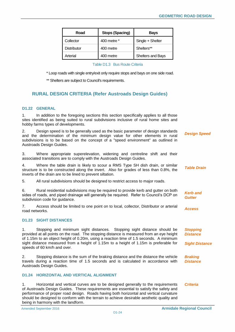
1. Bus routes will normally be identified by Council. It is important that the road hierarchy adequately caters for buses. The main criteria in determining the location of bus routes is that no more than 5% of residents should have to walk in excess of 400 metres to catch a bus. Normally roads above the local street in the hierarchy are designed as bus routes. Conformance with the Disability Discrimination Act and consultation with local bus service operators is required. Table D1.3 details minimum criteria for bus route design.
Criteria for Location
2. For rural bus stops, standard drawing 030-074 provides the recommended layout and standard drawings 030-078, 030-079 and 030-080 provide the arrangement of the approved bus shelter signage and structure design. Sight stopping distance must be considered in determining the location of any bus stop.
GEOMETRIC ROAD DESIGN
Amended September 2016 Armidale Regional Council D1-24
Road Stops (Spacing) Bays
Collector 400 metre * Single + Shelter
Distributor 400 metre Shelters**
Arterial 400 metre Shelters and Bays
Table D1.3 Bus Route Criteria
* Loop roads with single entry/exit only require stops and bays on one side road.
** Shelters are subject to Council's requirements.
RURAL DESIGN CRITERIA (Refer Austroads Design Guides)
D1.22 GENERAL
1. In addition to the foregoing sections this section specifically applies to all those sites identified as being suited to rural subdivisions inclusive of rural home sites and hobby farms types of developments.
2. Design speed is to be generally used as the basic parameter of design standards and the determination of the minimum design value for other elements in rural subdivisions is to be based on the concept of a "speed environment" as outlined in Austroads Design Guides.
Design Speed
3. Where appropriate superelevation, widening and centreline shift and their associated transitions are to comply with the Austroads Design Guides.
4. Where the table drain is likely to scour a RMS Type SH dish drain, or similar structure is to be constructed along the invert. Also for grades of less than 0.8%, the inverts of the drain are to be lined to prevent siltation.
Table Drain
5. All rural subdivisions should be designed to restrict access to major roads.
6. Rural residential subdivisions may be required to provide kerb and gutter on both sides of roads, and piped drainage will generally be required. Refer to Council’s DCP on subdivision code for guidance.
Kerb and Gutter
7. Access should be limited to one point on to local, collector, Distributor or arterial road networks.
Access
D1.23 SIGHT DISTANCES
1. Stopping and minimum sight distances. Stopping sight distance should be provided at all points on the road. The stopping distance is measured from an eye height of 1.15m to an object height of 0.20m, using a reaction time of 1.5 seconds. A minimum sight distance measured from a height of 1.15m to a height of 1.15m is preferable for speeds of 60 km/h and over.
Stopping Distance
Sight Distance
2. Stopping distance is the sum of the braking distance and the distance the vehicle travels during a reaction time of 1.5 seconds and is calculated in accordance with Austroads Design Guides.
Braking Distance
D1.24 HORIZONTAL AND VERTICAL ALIGNMENT
1. Horizontal and vertical curves are to be designed generally to the requirements of Austroads Design Guides. These requirements are essential to satisfy the safety and performance of proper road design. Roads having both horizontal and vertical curvature should be designed to conform with the terrain to achieve desirable aesthetic quality and being in harmony with the landform.
Criteria
GEOMETRIC ROAD DESIGN
Amended September 2016 Armidale Regional Council D1-25
D1.25 INTERSECTIONS
1. Intersections should generally be designed in accordance with the Austroads Design Guides. The type of intersection required will depend on existing and planned connecting roads.
Criteria
2. Adequate sight distance should be provided at intersections both horizontally and vertically. Each intersection location shall be examined for conformance with the criteria for Approach Sight Distance (ASD), Entering Sight Distance (ESD) and Safe Intersection Sight Distance (SISD).
ASD relates to the ability of drivers to observe the roadway layout at an anticipated approach speed.
ESD relates to the driver entering the intersection from a minor road and ability to observe the roadway layout and assess traffic gaps.
SISD relates to an overall check that vehicles utilising the intersection have sufficient visibility to allow reaction and deceleration so as to provide adequate stopping distance in potential collision situations.
Tabulated speed/sight distance requirements together with detailed explanations for each of the sight distance criteria are given in Austroads Design Guides. Repositioning of an intersection may be required to obtain conformance with the sight distance criteria.
Sight Distance
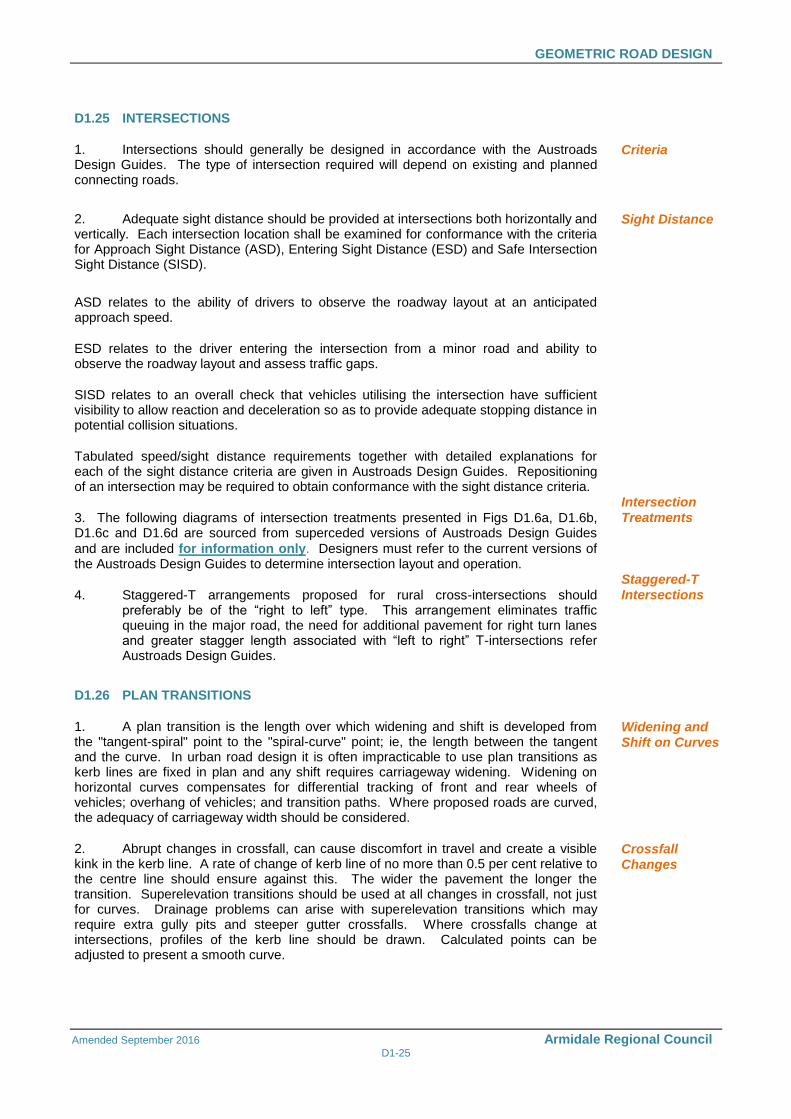
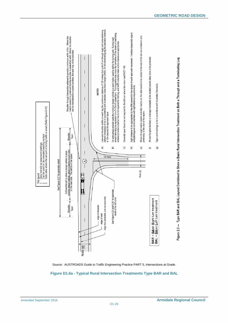
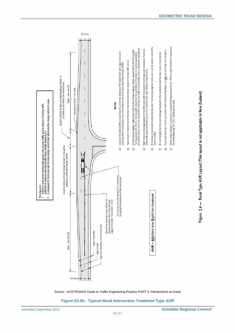
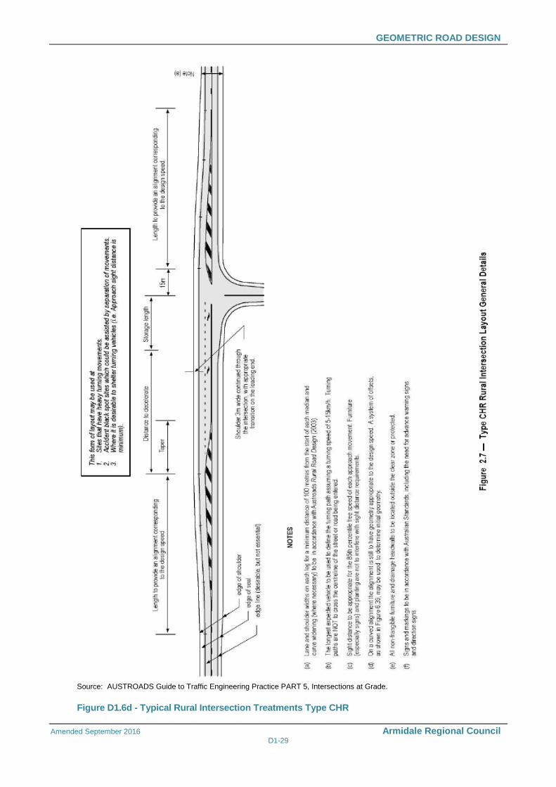
3. The following diagrams of intersection treatments presented in Figs D1.6a, D1.6b, D1.6c and D1.6d are sourced from superceded versions of Austroads Design Guides
and are included for information only. Designers must refer to the current versions of the Austroads Design Guides to determine intersection layout and operation.
Intersection Treatments
4. Staggered-T arrangements proposed for rural cross-intersections should preferably be of the “right to left” type. This arrangement eliminates traffic queuing in the major road, the need for additional pavement for right turn lanes and greater stagger length associated with “left to right” T-intersections refer Austroads Design Guides.
Staggered-T Intersections
D1.26 PLAN TRANSITIONS
1. A plan transition is the length over which widening and shift is developed from the "tangent-spiral" point to the "spiral-curve" point; ie, the length between the tangent and the curve. In urban road design it is often impracticable to use plan transitions as kerb lines are fixed in plan and any shift requires carriageway widening. Widening on horizontal curves compensates for differential tracking of front and rear wheels of vehicles; overhang of vehicles; and transition paths. Where proposed roads are curved, the adequacy of carriageway width should be considered.
Widening and Shift on Curves
2. Abrupt changes in crossfall, can cause discomfort in travel and create a visible kink in the kerb line. A rate of change of kerb line of no more than 0.5 per cent relative to the centre line should ensure against this. The wider the pavement the longer the transition. Superelevation transitions should be used at all changes in crossfall, not just for curves. Drainage problems can arise with superelevation transitions which may require extra gully pits and steeper gutter crossfalls. Where crossfalls change at intersections, profiles of the kerb line should be drawn. Calculated points can be adjusted to present a smooth curve.
Crossfall Changes
GEOMETRIC ROAD DESIGN
Amended September 2016 Armidale Regional Council D1-26
Source: AUSTROADS Guide to Traffic Engineering Practice PART 5, Intersections at Grade.
Figure D1.6a - Typical Rural Intersection Treatments Type BAR and BAL
GEOMETRIC ROAD DESIGN
Amended September 2016 Armidale Regional Council D1-27
Source: AUSTROADS Guide to Traffic Engineering Practice PART 5, Intersections at Grade
Figure D1.6b - Typical Rural Intersection Treatment Type AUR
GEOMETRIC ROAD DESIGN
Amended September 2016 Armidale Regional Council D1-28
Source: AUSTROADS Guide to Traffic Engineering Practice PART 5, Intersections at Grade.
Source: AUSTROADS Guide to Traffic Engineering Practice PART 5, Intersections at Grade.
Figure D1.6c - Typical Rural Intersection Treatments Type AUL
GEOMETRIC ROAD DESIGN
Amended September 2016 Armidale Regional Council D1-29
Source: AUSTROADS Guide to Traffic Engineering Practice PART 5, Intersections at Grade.
Figure D1.6d - Typical Rural Intersection Treatments Type CHR
GEOMETRIC ROAD DESIGN
Amended September 2016 Armidale Regional Council D1-30
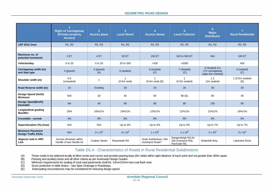
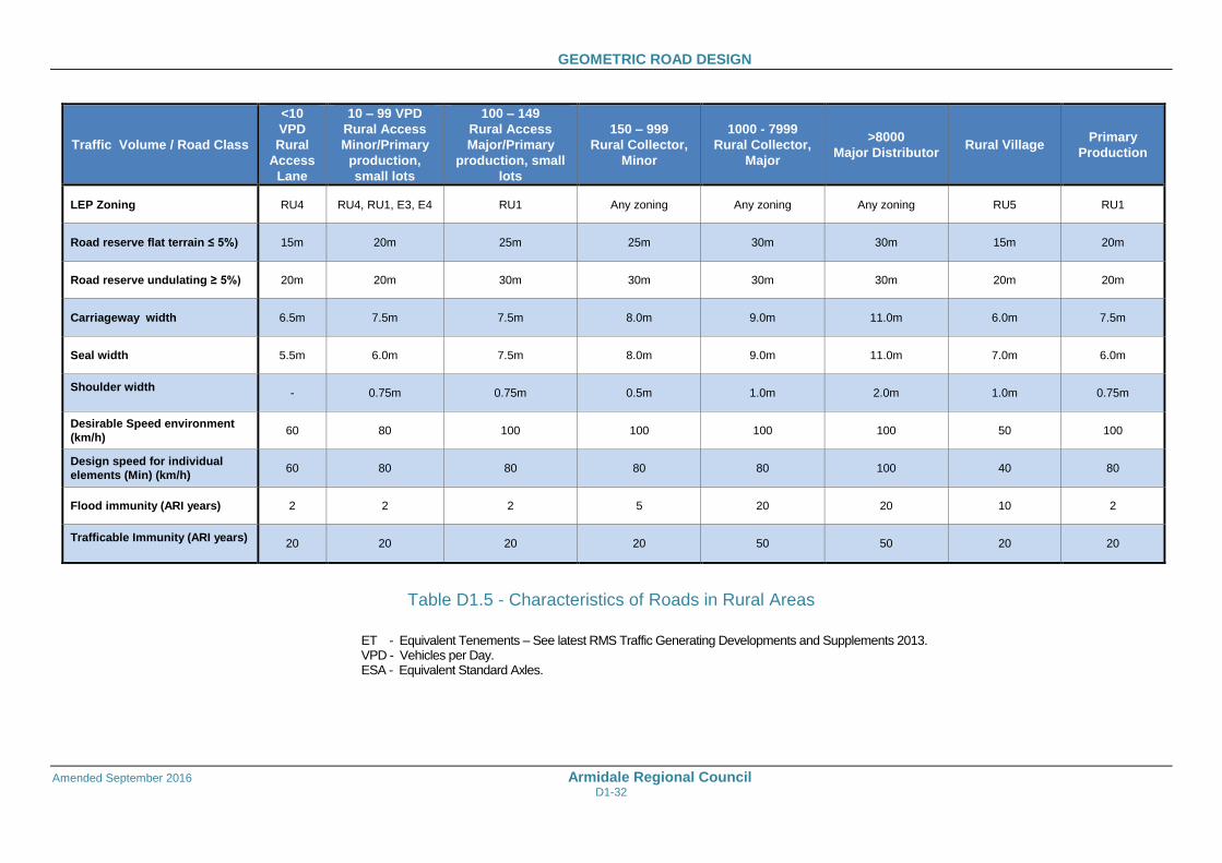
D1.27 CHARACTERISTICS OF RURAL ROADS
1. This section specifically applies to all those sites identified as being suited to rural subdivisions inclusive of rural home sites and hobby farm types of development. Table D1.4 and Table D1.5 provide the standards to be adopted for a variety of road types and LEP zones and Armidale Regional Council Standard Drawings 030-062 and 030-064 illustrate several road cross sections for typical road design situations.
Reference Tables
(a) Sealing shall be required for longitudinal grades in excess of 10% for the Rural Village RU5 zone and in excess of 16% for the RU1 and RU4 Rural zones and E3 and E4 Environmental zones. Where it is possible for the road to be extended to service additional lots, the road shall be constructed to a 6.0m seal standard. (b) Sealing may be required at sites where existing adjacent roads are sealed. In this instance the seal width shall match the adjoining seal with a minimum of 6.0m. (c) In undulating terrain this width shall be increased to enable services to be constructed on accessible flatter land on top and below batters. (d) Where the road is a designated on-road bicycle route (signposted and pavement marked) the shoulder provision needs to conform to the AUSTROADS ‘Guide to Road Design Part 6A: Pedestrian and Cyclist Paths’ (AGRD06A-09).
(e) Culverts shall be designed to accommodate flood immunity flows with a maximum headwater level 150mm below the shoulder level. Reference should be made to the supplement to Specification D5 – ‘Stormwater Drainage Design’. (f) The vertical alignment shall be designed such that the maximum overtopping depth is 200mm to achieve trafficable immunity. (g) For existing road reserves – if there is potential for further properties to access, then classification will be local minor.
Sealing
Bicycle Route
D1.28 SUPERELEVATION
1. Use of maximum superelevation will be considered where the radius of the curve in approaching the minimum speed environment. Reference should be made to Austroads Design Guides and superelevation calculation. At low and intermediate ranges of design speed (i.e. below 80 km/h) it is desirable to superelevate all curves at least to a value equal the normal crossfall of straights.
Design Speed
D1.29 SCOUR PROTECTION
1. Scour protection of roadside drainage and table drains is required. The level of protection will depend on the nature of the soils, road gradients and volume of stormwater runoff. Protection works may involve concrete lined channels, turfing, rock pitching, grass seeding, individually or any combination of these. Geotechnical investigations should be carried out of determine the level and extent of any protection works prior to proceeding to final design stage.
Roadside Drainage and Table Drains
GEOMETRIC ROAD DESIGN
Amended September 2016 Armidale Regional Council D1-31
1
Right of Carriageway
(Private property
Access)
2
Access place
3
Local Street
4
Access Street
5
Local Collector
6
Major
Distributor
7
Rural Residential
LEP 2012 Zone R1, R2 R1, R2 R1, R2 R1, R2 R1, R2 R1, R2 R2, R5
Maximum no. of
potential tenements 2 ET 4 ET 50 ET 150 ET 150 to 500 ET N/A 100 ET
Vehicles/day 0 to 20 0 to 20 20 to 200 >200 >2000 400
Carriageway width (m)
and Seal type 4 (gravel)
4 (gravel) (A)
6 (sealed) 6 (sealed)
(C) 7 (Sealed)
(C)
9 (Sealed) (C) (7m carriageway
edge line marked)
6 (sealed) (C)
Shoulder width (m) 0.5
(unsealed) 1
1 (0.5m seal)
1 (0.5m seal) (D)
1 (0.5m sealed)
1.2 (1m sealed)
1 (0.5m sealed) (D)
Road Reserve width (m) 10 Existing 20 20 20 30 20
Design Speed (km/h)
Minimum N/A 20 40 60 80 (E) 80 40
Design Speed(km/h)
Desirable NA 40 60 80 80 100 60
Longitudinal grading
Max/Min 20% 16%/1% 16%/1% 12%/1% 12%/1% 12%/1% 16%/1%
Crossfalls - normal 3% 3% 3% 3% 3% 3% 3%
Superelevation (%) (max) N/A N/A Up to 3% Up to 3% Up to 3% Up to 7% Up to 7%
Minimum Pavement
Design Traffic ESAs N/A 3 x 10
5 3 x 10
5 1 x 10
6 1 x 10
6 2 x 10
6 3 x 10
5
Atypical road in ARC
LGA
Access driveway within handle of axe handle lot
Coakes Street Roseneath Rd Hook Subdivision, Old Gostwyck Road?
Dangarsleigh Rd (to Old Gostwyck Rd), Rockvale Rd,
Waterfall Way Lakeview Drive
Table D1.4 - Characteristics of Roads in Rural Residential Subdivisions
(A) These roads to be widened locally at blind crests and curves and provide passing bays (6m wide) within sight distance of each point and not greater than 300m apart. (B) Passing and auxiliary lanes and all other criteria as per Austroads Design Guides. (C) Minimum requirements for sealing of rural road pavements shall be: 14mm/10mm two coat flush seal. (D) Scour protection in table drains – see Spec Drainage in Roadways. (E) Extenuating circumstances may be considered for reducing design speed
GEOMETRIC ROAD DESIGN
Amended September 2016 Armidale Regional Council D1-32
Traffic Volume / Road Class
<10
VPD
Rural
Access
Lane
10 – 99 VPD
Rural Access
Minor/Primary
production,
small lots
100 – 149
Rural Access
Major/Primary
production, small
lots
150 – 999
Rural Collector,
Minor
1000 - 7999
Rural Collector,
Major
>8000
Major Distributor Rural Village
Primary
Production
LEP Zoning RU4 RU4, RU1, E3, E4 RU1 Any zoning Any zoning Any zoning RU5 RU1
Road reserve flat terrain ≤ 5%) 15m 20m 25m 25m 30m 30m 15m 20m
Road reserve undulating ≥ 5%) 20m 20m 30m 30m 30m 30m 20m 20m
Carriageway width 6.5m 7.5m 7.5m 8.0m 9.0m 11.0m 6.0m 7.5m
Seal width 5.5m 6.0m 7.5m 8.0m 9.0m 11.0m 7.0m 6.0m
Shoulder width
- 0.75m 0.75m 0.5m 1.0m 2.0m 1.0m 0.75m
Desirable Speed environment
(km/h) 60 80 100 100 100 100 50 100
Design speed for individual
elements (Min) (km/h) 60 80 80 80 80 100 40 80
Flood immunity (ARI years) 2 2 2 5 20 20 10 2
Trafficable Immunity (ARI years)
20 20 20 20 50 50 20 20
Table D1.5 - Characteristics of Roads in Rural Areas
ET - Equivalent Tenements – See latest RMS Traffic Generating Developments and Supplements 2013. VPD - Vehicles per Day. ESA - Equivalent Standard Axles.
GEOMETRIC ROAD DESIGN
Amended September 2016 Armidale Regional Council D1-33
1
Shareway
2
Access place
3
Local Street &
Access Street
4
Local Collector
5
Major
Distributor
6
Arterial
7
Commercial
8
Industrial
LEP 2012 Zone R1 R1 R1 R1 R1 R1
Maximum no. of potential
tenements 6 ET 30 ET 75 ET 300 ET - - -
-
Vehicles/day Less than 60 61 - 300 300 - 750 751 - 3000 3001 to 10000 More than 10000 - -
Carriageway width (m)
kerb face to kerb face 5 6 8 11.2/11.6 (4) 11.6/13 (5) 13 13 13
Verge width (m)
Road Reserve width (m) 13 14 16 20 20 22 20 20
Kerb type One side only RT Rollover RT Rollover SA Barrier SA Barrier SA Barrier SA Barrier SA Barrier
Design Speed(km/h)
Desirable 15 25 40 50 50 80 40 50
Minimum distance
between intersections (m) - 30 60 80 80 500 60 60
Longitudinal grading
Max/Min 20% 18% 16% 12% 10% 10% 5% 10%
Pavement surface 25mm AC 25mm AC 25mm AC 40mm AC 40mm AC 40mm AC 40mm AC 40mm AC or Reinforced Concrete
Concrete footpath (m) No No No Yes (2) 1.2m Yes (2) No (2) Yes (2) No
Cycleway No No No Refer (2) Refer (3) Refer (2) No No
Minimum Pavement
Design Traffic ESAs 5 x 10
4 7 x 10
4 5 x 10
5 1 x 10
6 2 x 10
6 1 x 10
7 5 x 10
6
5 x 10⁶
(light)
1 x 10⁷
(heavy)
Atypical road in ARC LGA - - Dalton Drive Link Road Marsh Street Grafton Road Rusden Street Mann Street
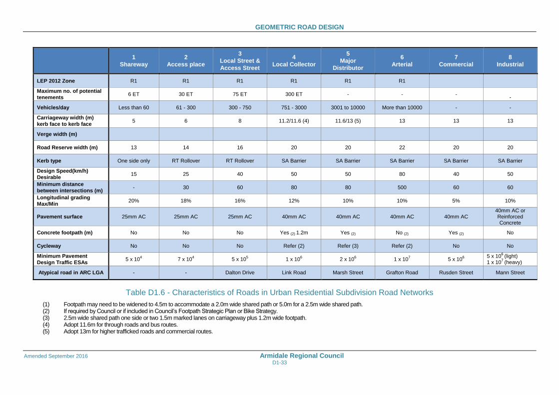
Table D1.6 - Characteristics of Roads in Urban Residential Subdivision Road Networks
(1) Footpath may need to be widened to 4.5m to accommodate a 2.0m wide shared path or 5.0m for a 2.5m wide shared path. (2) If required by Council or if included in Council’s Footpath Strategic Plan or Bike Strategy. (3) 2.5m wide shared path one side or two 1.5m marked lanes on carriageway plus 1.2m wide footpath. (4) Adopt 11.6m for through roads and bus routes. (5) Adopt 13m for higher trafficked roads and commercial routes.
GEOMETRIC ROAD DESIGN
Amended September 2016 Armidale Regional Council D1-34
SPECIAL REQUIREMENTS
D1.30 TURNING AREAS
Turning areas shall be provided at the termination of all roadways and shall generally have the dimensions given in Table D1.7
Turning Area Radii
D1.31 INDUSTRIAL ROAD WIDTHS
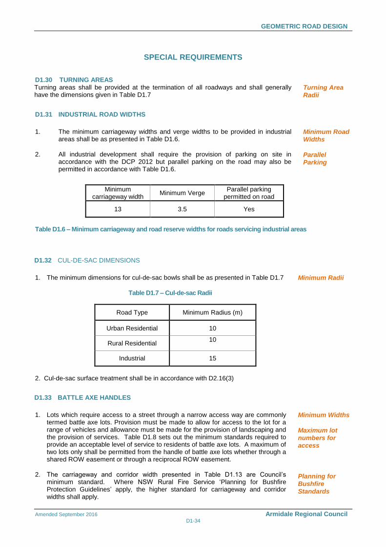
1. The minimum carriageway widths and verge widths to be provided in industrial areas shall be as presented in Table D1.6.
2. All industrial development shall require the provision of parking on site in accordance with the DCP 2012 but parallel parking on the road may also be permitted in accordance with Table D1.6.
Minimum Road Widths
Parallel Parking
Minimum carriageway width
Minimum Verge Parallel parking
permitted on road
13 3.5 Yes
Table D1.6 – Minimum carriageway and road reserve widths for roads servicing industrial areas
D1.32 CUL-DE-SAC DIMENSIONS
1. The minimum dimensions for cul-de-sac bowls shall be as presented in Table D1.7 Minimum Radii
Table D1.7 – Cul-de-sac Radii
Road Type Minimum Radius (m)
Urban Residential 10
Rural Residential 10
Industrial 15
2. Cul-de-sac surface treatment shall be in accordance with D2.16(3)
D1.33 BATTLE AXE HANDLES
1. Lots which require access to a street through a narrow access way are commonly termed battle axe lots. Provision must be made to allow for access to the lot for a range of vehicles and allowance must be made for the provision of landscaping and the provision of services. Table D1.8 sets out the minimum standards required to provide an acceptable level of service to residents of battle axe lots. A maximum of two lots only shall be permitted from the handle of battle axe lots whether through a shared ROW easement or through a reciprocal ROW easement.
2. The carriageway and corridor width presented in Table D1.13 are Council’s minimum standard. Where NSW Rural Fire Service ‘Planning for Bushfire Protection Guidelines’ apply, the higher standard for carriageway and corridor widths shall apply.
Minimum Widths
Maximum lot numbers for access
Planning for Bushfire Standards
GEOMETRIC ROAD DESIGN
Amended September 2016 Armidale Regional Council D1-35
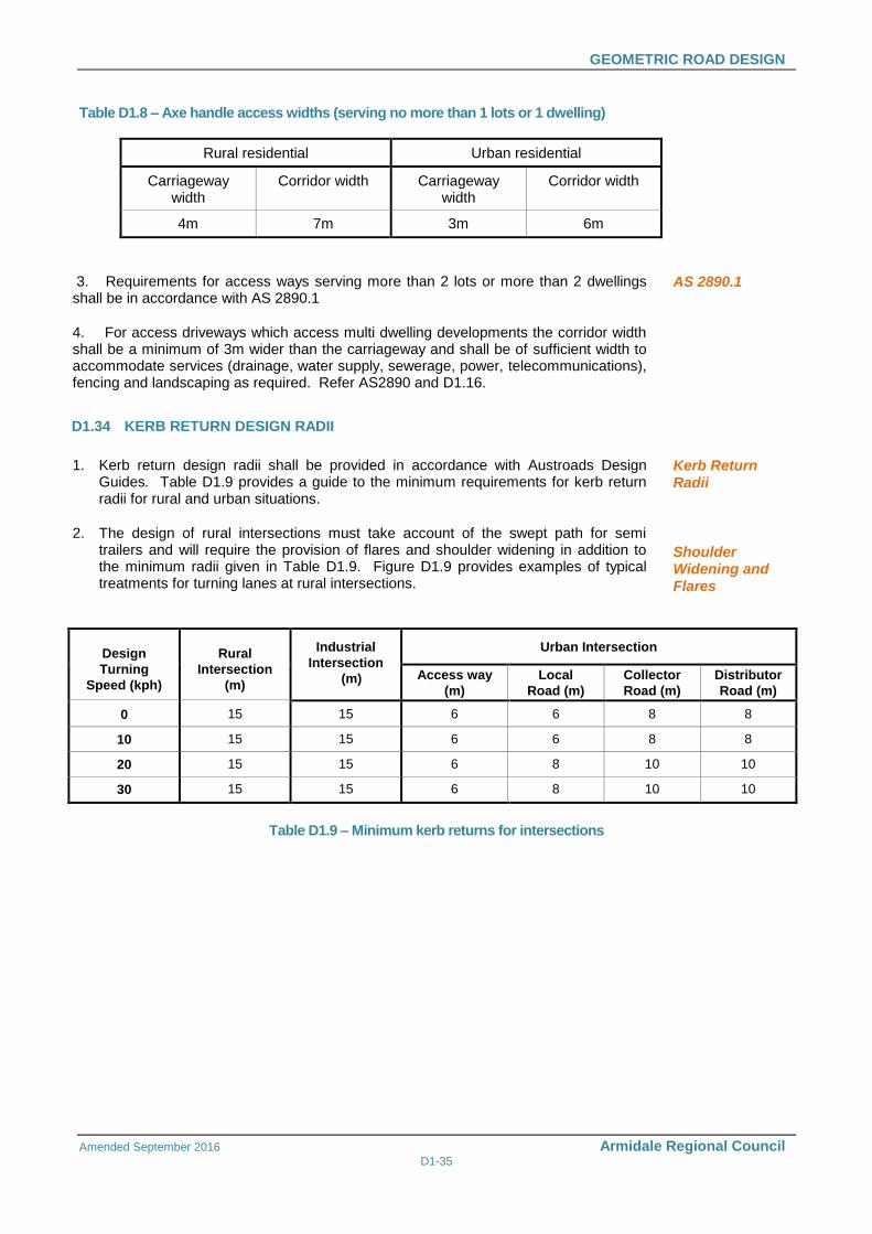
Table D1.8 – Axe handle access widths (serving no more than 1 lots or 1 dwelling)
Rural residential Urban residential
Carriageway width
Corridor width Carriageway width
Corridor width
4m 7m 3m 6m
3. Requirements for access ways serving more than 2 lots or more than 2 dwellings shall be in accordance with AS 2890.1
4. For access driveways which access multi dwelling developments the corridor width shall be a minimum of 3m wider than the carriageway and shall be of sufficient width to accommodate services (drainage, water supply, sewerage, power, telecommunications), fencing and landscaping as required. Refer AS2890 and D1.16.
AS 2890.1
D1.34 KERB RETURN DESIGN RADII
1. Kerb return design radii shall be provided in accordance with Austroads Design Guides. Table D1.9 provides a guide to the minimum requirements for kerb return radii for rural and urban situations.
2. The design of rural intersections must take account of the swept path for semi trailers and will require the provision of flares and shoulder widening in addition to the minimum radii given in Table D1.9. Figure D1.9 provides examples of typical treatments for turning lanes at rural intersections.
Kerb Return Radii
Shoulder Widening and Flares
Design
Turning
Speed (kph)
Rural
Intersection
(m)
Industrial
Intersection
(m)
Urban Intersection
Access way
(m)
Local
Road (m)
Collector
Road (m)
Distributor
Road (m)
0 15 15 6 6 8 8
10 15 15 6 6 8 8
20 15 15 6 8 10 10
30 15 15 6 8 10 10
Table D1.9 – Minimum kerb returns for intersections
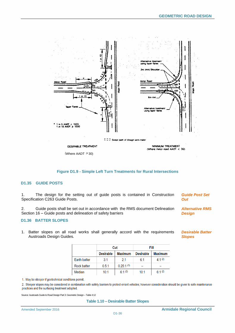
GEOMETRIC ROAD DESIGN
Amended September 2016 Armidale Regional Council D1-36
(Where AADT 30)
Figure D1.9 - Simple Left Turn Treatments for Rural Intersections
D1.35 GUIDE POSTS
1. The design for the setting out of guide posts is contained in Construction Specification C263 Guide Posts.
Guide Post Set Out
2. Guide posts shall be set out in accordance with the RMS document Delineation Section 16 – Guide posts and delineation of safety barriers
Alternative RMS Design
D1.36 BATTER SLOPES
1. Batter slopes on all road works shall generally accord with the requirements Austroads Design Guides.
Desirable Batter Slopes
Source: Austroads Guide to Road Design Part 3: Geometric Design – Table 4:12
Table 1.10 – Desirable Batter Slopes
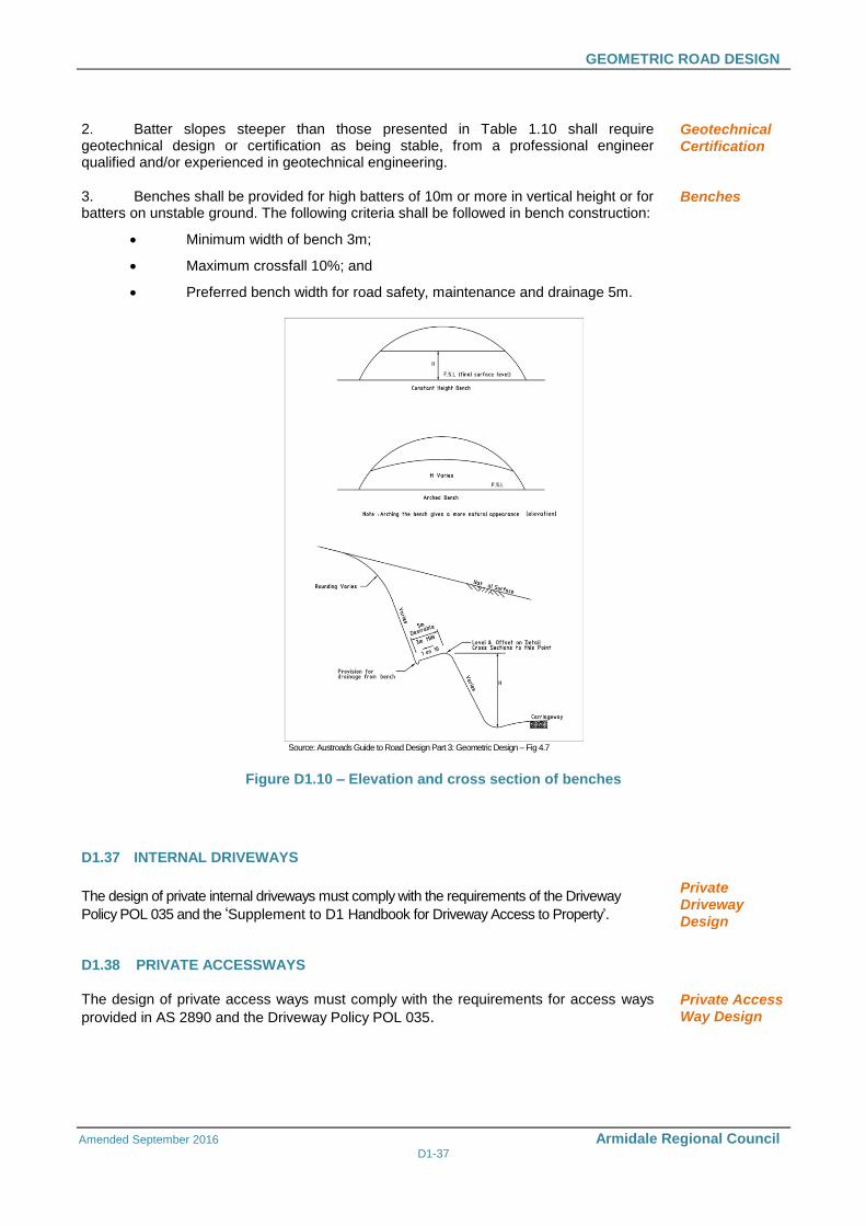
GEOMETRIC ROAD DESIGN
Amended September 2016 Armidale Regional Council D1-37
2. Batter slopes steeper than those presented in Table 1.10 shall require geotechnical design or certification as being stable, from a professional engineer qualified and/or experienced in geotechnical engineering.
Geotechnical Certification
3. Benches shall be provided for high batters of 10m or more in vertical height or for batters on unstable ground. The following criteria shall be followed in bench construction:
Minimum width of bench 3m;
Maximum crossfall 10%; and
Preferred bench width for road safety, maintenance and drainage 5m.
Benches
Source: Austroads Guide to Road Design Part 3: Geometric Design – Fig 4.7
Figure D1.10 – Elevation and cross section of benches
D1.37 INTERNAL DRIVEWAYS
The design of private internal driveways must comply with the requirements of the Driveway
Policy POL 035 and the ‘Supplement to D1 Handbook for Driveway Access to Property’.
Private Driveway Design
D1.38 PRIVATE ACCESSWAYS
The design of private access ways must comply with the requirements for access ways
provided in AS 2890 and the Driveway Policy POL 035. Private Access Way Design
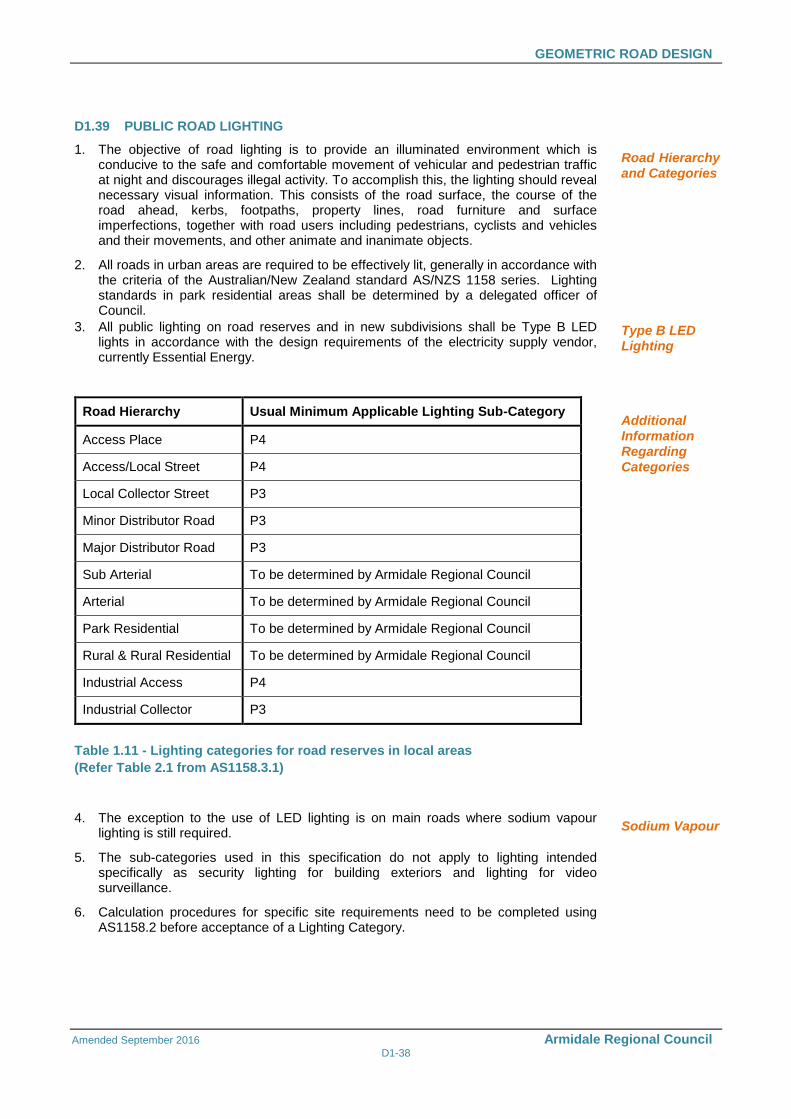
GEOMETRIC ROAD DESIGN
Amended September 2016 Armidale Regional Council D1-38
D1.39 PUBLIC ROAD LIGHTING
1. The objective of road lighting is to provide an illuminated environment which is conducive to the safe and comfortable movement of vehicular and pedestrian traffic at night and discourages illegal activity. To accomplish this, the lighting should reveal necessary visual information. This consists of the road surface, the course of the road ahead, kerbs, footpaths, property lines, road furniture and surface imperfections, together with road users including pedestrians, cyclists and vehicles and their movements, and other animate and inanimate objects.
2. All roads in urban areas are required to be effectively lit, generally in accordance with the criteria of the Australian/New Zealand standard AS/NZS 1158 series. Lighting standards in park residential areas shall be determined by a delegated officer of Council.
3. All public lighting on road reserves and in new subdivisions shall be Type B LED lights in accordance with the design requirements of the electricity supply vendor, currently Essential Energy.
Road Hierarchy and Categories
Type B LED Lighting
Road Hierarchy Usual Minimum Applicable Lighting Sub-Category
Access Place P4
Access/Local Street P4
Local Collector Street P3
Minor Distributor Road P3
Major Distributor Road P3
Sub Arterial To be determined by Armidale Regional Council
Arterial To be determined by Armidale Regional Council
Park Residential To be determined by Armidale Regional Council
Rural & Rural Residential To be determined by Armidale Regional Council
Industrial Access P4
Industrial Collector P3
Table 1.11 - Lighting categories for road reserves in local areas
(Refer Table 2.1 from AS1158.3.1)
Additional Information Regarding Categories
4. The exception to the use of LED lighting is on main roads where sodium vapour lighting is still required.
5. The sub-categories used in this specification do not apply to lighting intended specifically as security lighting for building exteriors and lighting for video surveillance.
6. Calculation procedures for specific site requirements need to be completed using AS1158.2 before acceptance of a Lighting Category.
Sodium Vapour
GEOMETRIC ROAD DESIGN
Amended September 2016 Armidale Regional Council D1-39
7. Alternative categories may be considered under direction of Council
Category P Lighting – Lighting that is applicable to roads and other outdoor public spaces on which the visual requirements of pedestrians are dominant, e.g. local roads, outdoor shopping precincts and outdoor car parks.
a) Calculation procedures for specific site requirements need to be completed using AS1158.2 before acceptance of a Lighting Category.
b) Category P Lighting is provided for pedestrians, not motorists, with the exception of the lighting of LATMS, which are intended to reveal sufficient details of the device to allow approaching vehicles to navigate through the devices appropriately. This is a lower standard (Category V) than the standard for pedestrian lighting so the higher standard Category P will be used in preference. Alternative categories may be considered under direction of Council.
Category P Lighting – Lighting that is applicable to roads and other outdoor public spaces on which the visual requirements of pedestrians are dominant, e.g. local roads, outdoor shopping precincts and outdoor car parks.
Public Road Lighting
D1.40 LINEMARKING
1. Line marking shall be undertaken to comply with RMS Specifications R141, R145 and the Delineation Manual, and the requirements of the RMCC Contract. Thermo-plastic markings shall be used in areas of high traffic volumes i.e. Roundabout Holding lines and Pedestrian Crossings. Generally, the use of thermo-plastic markings is considered on a case by case basis.
Thermo-plastic Markings
D1.41 SIGNS
1. Street signs shall be provided in accordance with the following requirements:
• The street sign naming process shall be undertaken through council. The Planning Department of Council manage the process through the Geographical Names Board
• Signs shall be provided and installed by Council at the developers cost
• Installation shall be in accordance with the standard drawing
Street Signs
2. Road signs shall be provided in accordance with the following requirements:
• Sign faces and installation shall be in accordance with AS1742
• Signs shall be provided and installed by Council at the developers cost
• Installation shall be in accordance with the standard drawing
Road signs
D1.42 SHOULDERS
1. Road shoulders shall be designed to carry out the following functions:
Provide lateral support to the road pavement layers.
Provide an initial recovery for an errant vehicle, emergency use, a refuge for stopped vehicles and space for cyclists.
2. Shoulder width shall be:
Generally: 1.5m to 2.0m.
For higher volume roads: 2.5m to 3.0 m.
Function
Width
GEOMETRIC ROAD DESIGN
Amended September 2016 Armidale Regional Council D1-40
3. Shoulders may be sealed partially or wholly to reduce maintenance costs, to improve road user safety and to improve moisture conditions under pavements. Sealed shoulders shall conform to the following sealed widths:
a) Minimum width of shoulder seal for AADT < 1000 shall be 0.5m.
b) For wet areas where moisture control is required:
• Desirable shoulder seal width shall be 0.5m.
• Preferred shoulder seal width shall be 1.0m.
c) For discretionary stopping of cars shoulder width shall be 2.5 m.
d) For bicycles, minimum sealed shoulder width shall be 2.0m to 3.0m.
4. The following shoulder crossfalls shall be provided:
• For earth and loam: 5% to 6%.
• For gravel or crushed rock: 4% to 5%.
• For concrete and for full depth pavement with bitumen seal or asphalt wearing course, match with the traffic lane.
Sealed Shoulders
Crossfall
D1.43 ROADSIDE DRAINAGE
1. Roadside drainage shall be provided to remove water from the road and its surroundings and to maintain road safety and pavement strength. Drainage infrastructure shall include where appropriate table drains, catch drains, median drains and kerbs and channels.
2. Table drains shall be formed as a dish drain adjacent to the road shoulder with the invert of table drains to typically match subgrade level and be of minimum depth 500mm below shoulder level. Where scour is likely to occur, the outer edges of the pavement and the shoulder verges shall be sealed and the invert of the drain shall be lined. The following batter slopes shall be provided on formed table drains:
• Side slopes minimum requirement: < 4H:1V.
• Desirable slope: 6H:1V.
3. Catch drains shall be provided to prevent overloading of the table drain and to minimise scour of the batter face. They shall be placed at least 2 m from the edge of cuttings to minimise possible undercutting of the top of the batter.
4. Median drains shall be constructed with side slopes of 10H: 1V to reduce the chance of an errant vehicle from overturning. A depressed median of minimum width10 m shall be provided with the invert of the median drain below subgrade level to facilitate drainage of pavement layers.
General
Table drains
Catch Drains
Median Drains
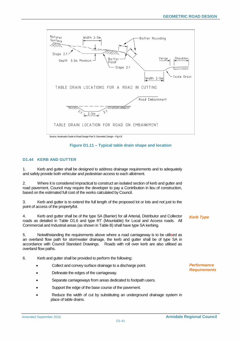
GEOMETRIC ROAD DESIGN
Amended September 2016 Armidale Regional Council D1-41
Source: Austroads Guide to Road Design Part 3: Geometric Design – Fig 4.8
Figure D1.11 – Typical table drain shape and location
D1.44 KERB AND GUTTER
1. Kerb and gutter shall be designed to address drainage requirements and to adequately and safely provide both vehicular and pedestrian access to each allotment.
2. Where it is considered impractical to construct an isolated section of kerb and gutter and road pavement, Council may require the developer to pay a Contribution in lieu of construction, based on the estimated full cost of the works calculated by Council.
3. Kerb and gutter is to extend the full length of the proposed lot or lots and not just to the point of access of the property/lot.
4. Kerb and gutter shall be of the type SA (Barrier) for all Arterial, Distributor and Collector roads as detailed in Table D1.6 and type RT (Mountable) for Local and Access roads. All Commercial and Industrial areas (as shown in Table B) shall have type SA kerbing.
5. Notwithstanding the requirements above where a road carriageway is to be utilised as an overland flow path for stormwater drainage, the kerb and gutter shall be of type SA in accordance with Council Standard Drawings. Roads with roll over kerb are also utilised as overland flow paths.
6. Kerb and gutter shall be provided to perform the following:
Collect and convey surface drainage to a discharge point.
Delineate the edges of the carriageway.
Separate carriageways from areas dedicated to footpath users.
Support the edge of the base course of the pavement.
Reduce the width of cut by substituting an underground drainage system in place of table drains.
Kerb Type
Performance Requirements
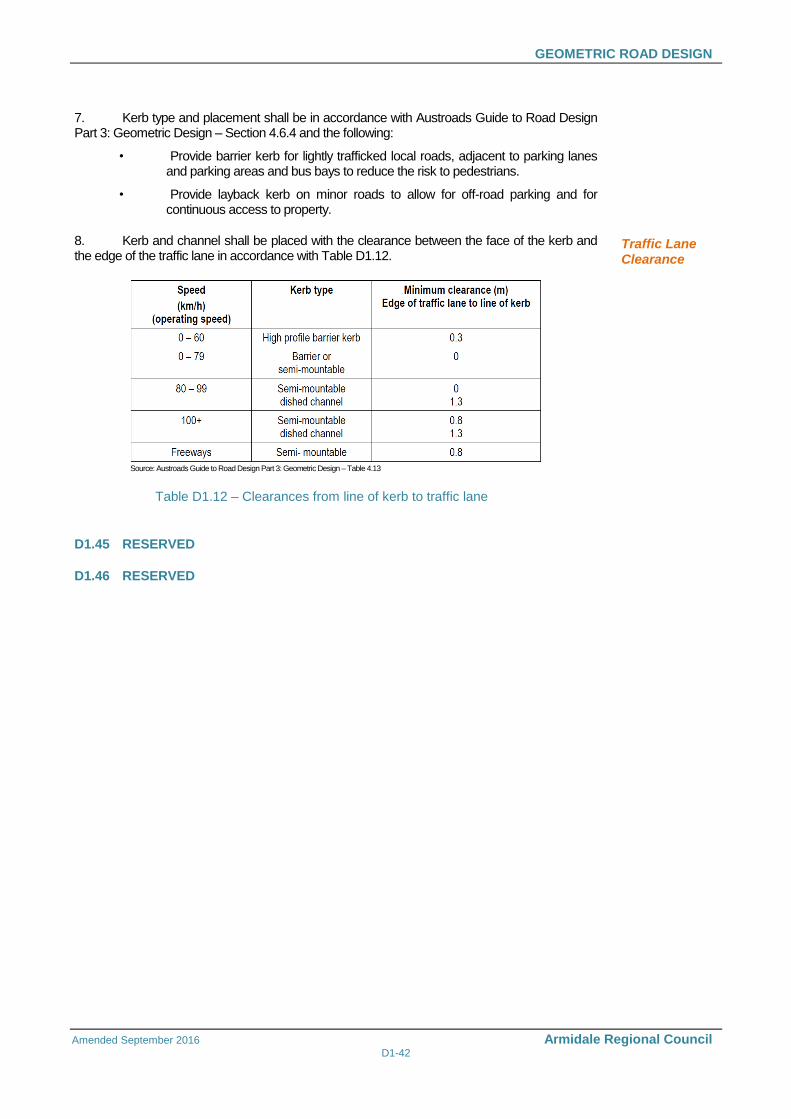
GEOMETRIC ROAD DESIGN
Amended September 2016 Armidale Regional Council D1-42
7. Kerb type and placement shall be in accordance with Austroads Guide to Road Design Part 3: Geometric Design – Section 4.6.4 and the following:
• Provide barrier kerb for lightly trafficked local roads, adjacent to parking lanes and parking areas and bus bays to reduce the risk to pedestrians.
• Provide layback kerb on minor roads to allow for off-road parking and for continuous access to property.
8. Kerb and channel shall be placed with the clearance between the face of the kerb and the edge of the traffic lane in accordance with Table D1.12.
Source: Austroads Guide to Road Design Part 3: Geometric Design – Table 4.13
Table D1.12 – Clearances from line of kerb to traffic lane
Traffic Lane Clearance
D1.45 RESERVED
D1.46 RESERVED