engineering design and installation guidelines - … .pdf · engineering design and installation...
TRANSCRIPT
© Iplex Pipelines Australia Pty Limited 2007
Revision No. 1.3 July 2008
Engineering Design and Installation Guidelines
Iplex Pipelines Australia Pty Limited ACN 079 613 308
Corner Southpine and Johnstone Roads (PO Box 5160)
BRENDALE QLD 4500
www.iplex.com.au Telephone: 13 18 40 Facsimile: 13 18 60
© Iplex Pipelines Australia Pty Limited 2007
Table of Contents
Introduction .......................................................................................................... 4
Iplex Pipelines ............................................................................................. 4 WSUD Source Control ................................................................................ 4 RainCell Stormwater Management System............................................... 5
Typical Applications ............................................................................................ 6 Infiltration..................................................................................................... 6 Storage and Reuse...................................................................................... 6 Attenuation .................................................................................................. 6 Conveyance and Bioretention Swales....................................................... 6 Brownfield and Salinity Hazard Sites ........................................................ 7
RainCell Features and Benefits .......................................................................... 7 Material Properties............................................................................................... 8 Product Range...................................................................................................... 8
RainCell ........................................................................................................ 8 Shear Connector ......................................................................................... 8 Locking Clip................................................................................................. 8 General Assembly Method ......................................................................... 9
Hydraulic Design.................................................................................................. 9 RainCell Hydraulic Performance.............................................................. 10
Structural Design ............................................................................................... 11 Traffic Loads.............................................................................................. 11 Viscoelastic Creep and Design Safety Factor ........................................ 11 RainCell Structural Performance ............................................................. 12 Minimum Cover Depth .............................................................................. 12 Maximum Installation Depth..................................................................... 13
Installation .......................................................................................................... 14 Typical Infiltration Gallery Installation Method....................................... 14 Typical Storage Tank Installation Method............................................... 15 Typical Bioretention Grassed Swale Installation Method...................... 16
RainCell Specification........................................................................................ 17
© Iplex Pipelines Australia Pty Limited 2007
Important Disclaimer The information, opinions, advice and recommendations contained in this publication are offered only with the object of providing a better understanding of technical matters associated with RainCell’s design, with Iplex Pipelines assuring no duty of care in respect of them. This publication should not be used as the sole source of information. As it does not refer to all relevant sources of information, reference should also be made to established textbooks and other published material. Readers should not act or rely upon any information contained in this publication without taking appropriate professional advice, which relates to their particular circumstances. RainCells and fittings are shown as typical configurations, however, in some cases, product dimensions and properties may vary or be changed without notice. If a dimension or property is critical please contact Iplex Pipelines Technical Marketing Group for clarification.
© Iplex Pipelines Australia Pty Limited 2007
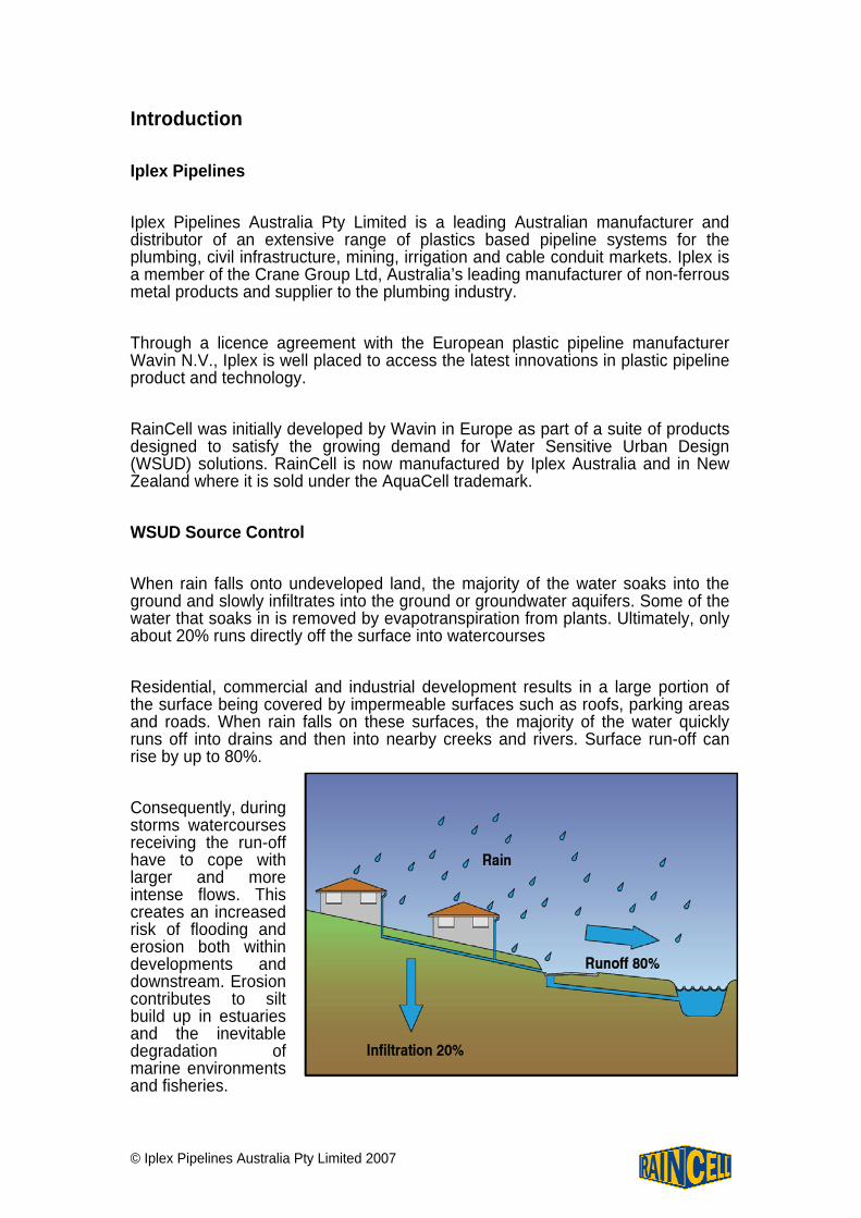
Introduction Iplex Pipelines Iplex Pipelines Australia Pty Limited is a leading Australian manufacturer and distributor of an extensive range of plastics based pipeline systems for the plumbing, civil infrastructure, mining, irrigation and cable conduit markets. Iplex is a member of the Crane Group Ltd, Australia’s leading manufacturer of non-ferrous metal products and supplier to the plumbing industry. Through a licence agreement with the European plastic pipeline manufacturer Wavin N.V., Iplex is well placed to access the latest innovations in plastic pipeline product and technology. RainCell was initially developed by Wavin in Europe as part of a suite of products designed to satisfy the growing demand for Water Sensitive Urban Design (WSUD) solutions. RainCell is now manufactured by Iplex Australia and in New Zealand where it is sold under the AquaCell trademark. WSUD Source Control When rain falls onto undeveloped land, the majority of the water soaks into the ground and slowly infiltrates into the ground or groundwater aquifers. Some of the water that soaks in is removed by evapotranspiration from plants. Ultimately, only about 20% runs directly off the surface into watercourses Residential, commercial and industrial development results in a large portion of the surface being covered by impermeable surfaces such as roofs, parking areas and roads. When rain falls on these surfaces, the majority of the water quickly runs off into drains and then into nearby creeks and rivers. Surface run-off can rise by up to 80%. Consequently, during storms watercourses receiving the run-off have to cope with larger and more intense flows. This creates an increased risk of flooding and erosion both within developments and downstream. Erosion contributes to silt build up in estuaries and the inevitable degradation of marine environments and fisheries.
© Iplex Pipelines Australia Pty Limited 2007
Stormwater run-off from impermeable urban surfaces also picks up and carries pollutants, including heavy metals, nutrients and hydrocarbons that can adversely affect the environment into receiving waters. Australian EPA’s and local authorities have confirmed a strong commitment to water sensitive urban developments. Source control is one of a number of techniques that contributes to WSUD. The principal aims of WSUD are:
• To limit run-off from developed areas to similar levels that were usual pre-development,
• Reuse stormwater for non-potable applications, • To improve the quality of the run-off, and • To improve public amenity.
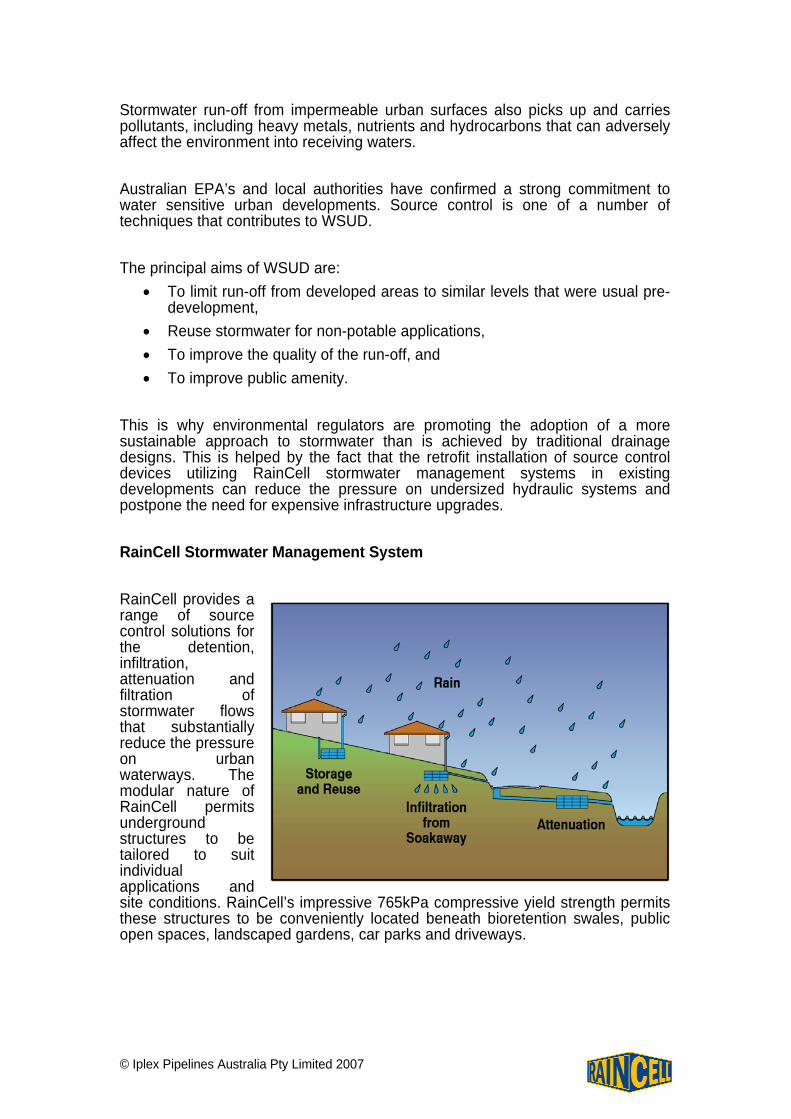
This is why environmental regulators are promoting the adoption of a more sustainable approach to stormwater than is achieved by traditional drainage designs. This is helped by the fact that the retrofit installation of source control devices utilizing RainCell stormwater management systems in existing developments can reduce the pressure on undersized hydraulic systems and postpone the need for expensive infrastructure upgrades. RainCell Stormwater Management System RainCell provides a range of source control solutions for the detention, infiltration, attenuation and filtration of stormwater flows that substantially reduce the pressure on urban waterways. The modular nature of RainCell permits underground structures to be tailored to suit individual applications and site conditions. RainCell’s impressive 765kPa compressive yield strength permits these structures to be conveniently located beneath bioretention swales, public open spaces, landscaped gardens, car parks and driveways.
© Iplex Pipelines Australia Pty Limited 2007
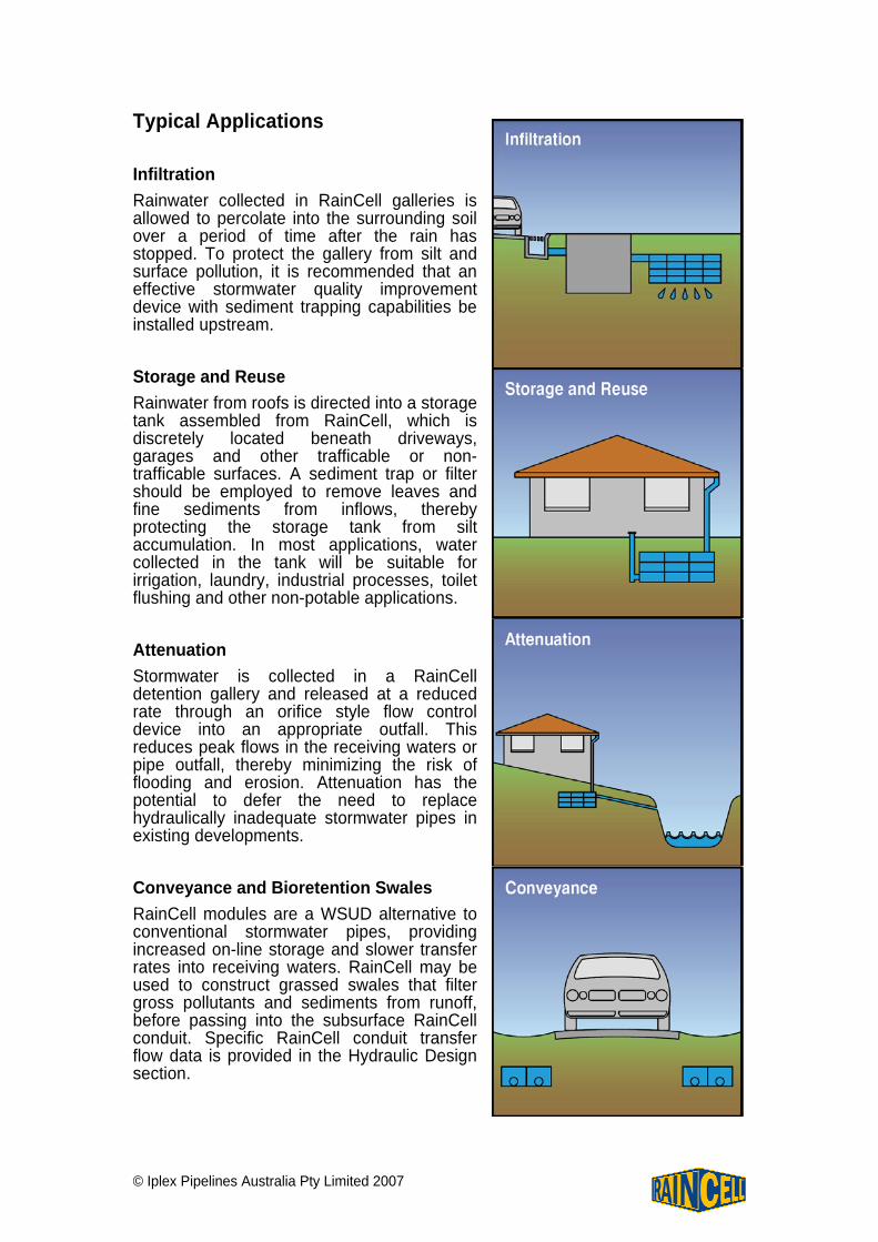
Typical Applications Infiltration Rainwater collected in RainCell galleries is allowed to percolate into the surrounding soil over a period of time after the rain has stopped. To protect the gallery from silt and surface pollution, it is recommended that an effective stormwater quality improvement device with sediment trapping capabilities be installed upstream. Storage and Reuse Rainwater from roofs is directed into a storage tank assembled from RainCell, which is discretely located beneath driveways, garages and other trafficable or non-trafficable surfaces. A sediment trap or filter should be employed to remove leaves and fine sediments from inflows, thereby protecting the storage tank from silt accumulation. In most applications, water collected in the tank will be suitable for irrigation, laundry, industrial processes, toilet flushing and other non-potable applications. Attenuation Stormwater is collected in a RainCell detention gallery and released at a reduced rate through an orifice style flow control device into an appropriate outfall. This reduces peak flows in the receiving waters or pipe outfall, thereby minimizing the risk of flooding and erosion. Attenuation has the potential to defer the need to replace hydraulically inadequate stormwater pipes in existing developments. Conveyance and Bioretention Swales RainCell modules are a WSUD alternative to conventional stormwater pipes, providing increased on-line storage and slower transfer rates into receiving waters. RainCell may be used to construct grassed swales that filter gross pollutants and sediments from runoff, before passing into the subsurface RainCell conduit. Specific RainCell conduit transfer flow data is provided in the Hydraulic Design section.
© Iplex Pipelines Australia Pty Limited 2007
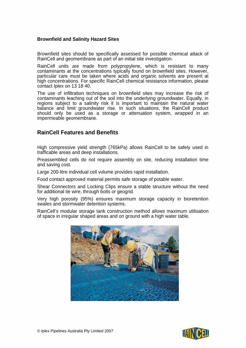
Brownfield and Salinity Hazard Sites Brownfield sites should be specifically assessed for possible chemical attack of RainCell and geomembrane as part of an initial site investigation. RainCell units are made from polypropylene, which is resistant to many contaminants at the concentrations typically found on brownfield sites. However, particular care must be taken where acids and organic solvents are present at high concentrations. For specific RainCell chemical resistance information, please contact Iplex on 13 18 40. The use of infiltration techniques on brownfield sites may increase the risk of contaminants leaching out of the soil into the underlying groundwater. Equally, in regions subject to a salinity risk it is important to maintain the natural water balance and limit groundwater rise. In such situations, the RainCell product should only be used as a storage or attenuation system, wrapped in an impermeable geomembrane. RainCell Features and Benefits High compressive yield strength (765kPa) allows RainCell to be safely used in trafficable areas and deep installations. Preassembled cells do not require assembly on site, reducing installation time and saving cost. Large 200-litre individual cell volume provides rapid installation. Food contact approved material permits safe storage of potable water. Shear Connectors and Locking Clips ensure a stable structure without the need for additional tie wire, through bolts or geogrid. Very high porosity (95%) ensures maximum storage capacity in bioretention swales and stormwater detention systems. RainCell’s modular storage tank construction method allows maximum utilisation of space in irregular shaped areas and on ground with a high water table.
© Iplex Pipelines Australia Pty Limited 2007
Material Properties
Property Test Method Unit Value / Description
Polypropylene Block Copolymer FDA 177.1520 - Food contact approved
Density ASTM D1505 kg/m3 900
Tensile Yield Strength ASTM D638 MPa 22.6
Elongation at Break ASTM D638 % >100
Flexural Modulus ASTM D790 MPa 1,180
Heat Distortion Temperature ASTM D648 °C 103
Rockwell Hardness ASTM D785 R-Scale 87
Izod Impact Strength [+23° C]
[-10° C]
ASTM D256 J/m 118
53.9
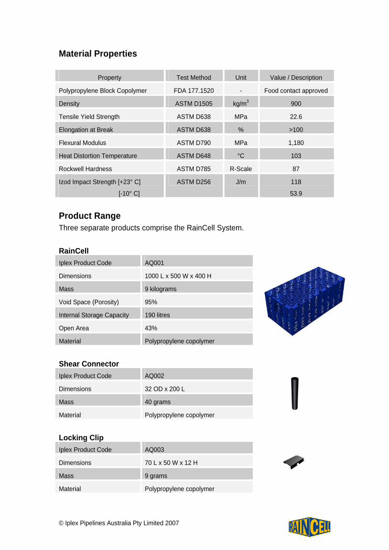
Product Range Three separate products comprise the RainCell System. RainCell Iplex Product Code AQ001
Dimensions 1000 L x 500 W x 400 H
Mass 9 kilograms
Void Space (Porosity) 95%
Internal Storage Capacity 190 litres
Open Area 43%
Material Polypropylene copolymer
Shear Connector Iplex Product Code AQ002
Dimensions 32 OD x 200 L
Mass 40 grams
Material Polypropylene copolymer
Locking Clip Iplex Product Code AQ003
Dimensions 70 L x 50 W x 12 H
Mass 9 grams
Material Polypropylene copolymer
© Iplex Pipelines Australia Pty Limited 2007
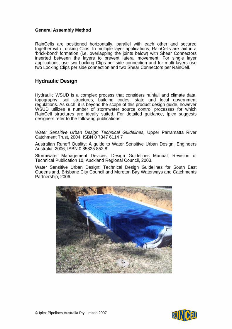
General Assembly Method RainCells are positioned horizontally, parallel with each other and secured together with Locking Clips. In multiple layer applications, RainCells are laid in a ‘brick-bond’ formation (i.e. overlapping the joints below) with Shear Connectors inserted between the layers to prevent lateral movement. For single layer applications, use two Locking Clips per side connection and for multi layers use two Locking Clips per side connection and two Shear Connectors per RainCell. Hydraulic Design Hydraulic WSUD is a complex process that considers rainfall and climate data, topography, soil structures, building codes, state and local government regulations. As such, it is beyond the scope of this product design guide, however WSUD utilizes a number of stormwater source control processes for which RainCell structures are ideally suited. For detailed guidance, Iplex suggests designers refer to the following publications: Water Sensitive Urban Design Technical Guidelines, Upper Parramatta River Catchment Trust, 2004, ISBN 0 7347 6114 7 Australian Runoff Quality: A guide to Water Sensitive Urban Design, Engineers Australia, 2006, ISBN 0 85825 852 8 Stormwater Management Devices: Design Guidelines Manual, Revision of Technical Publication 10, Auckland Regional Council, 2003. Water Sensitive Urban Design: Technical Design Guidelines for South East Queensland, Brisbane City Council and Moreton Bay Waterways and Catchments Partnership, 2006.
© Iplex Pipelines Australia Pty Limited 2007
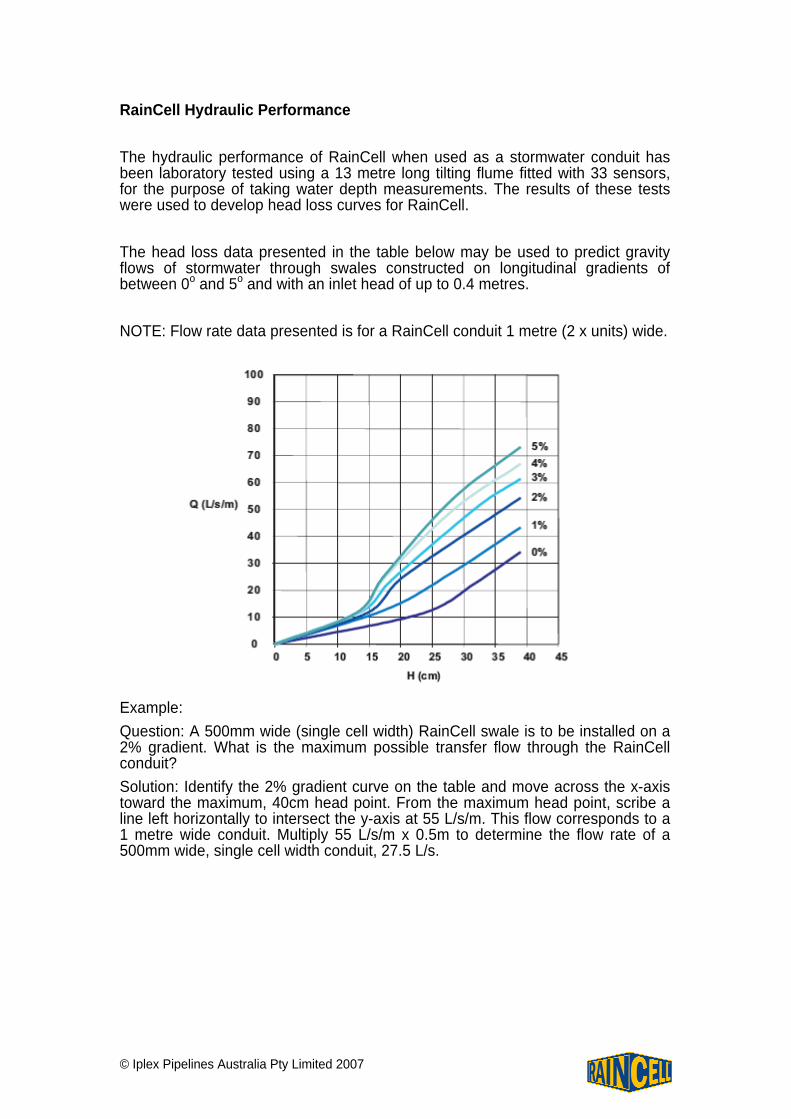
RainCell Hydraulic Performance The hydraulic performance of RainCell when used as a stormwater conduit has been laboratory tested using a 13 metre long tilting flume fitted with 33 sensors, for the purpose of taking water depth measurements. The results of these tests were used to develop head loss curves for RainCell. The head loss data presented in the table below may be used to predict gravity flows of stormwater through swales constructed on longitudinal gradients of between 0o and 5o and with an inlet head of up to 0.4 metres. NOTE: Flow rate data presented is for a RainCell conduit 1 metre (2 x units) wide. Example: Question: A 500mm wide (single cell width) RainCell swale is to be installed on a 2% gradient. What is the maximum possible transfer flow through the RainCell conduit? Solution: Identify the 2% gradient curve on the table and move across the x-axis toward the maximum, 40cm head point. From the maximum head point, scribe a line left horizontally to intersect the y-axis at 55 L/s/m. This flow corresponds to a 1 metre wide conduit. Multiply 55 L/s/m x 0.5m to determine the flow rate of a 500mm wide, single cell width conduit, 27.5 L/s.
© Iplex Pipelines Australia Pty Limited 2007
Structural Design Traffic Loads The modular nature of the RainCell system means it has a broad range of applications. Units can be placed under a wide variety of landscaped or trafficked areas. RainCell can be used under areas trafficked by heavy goods vehicles, however design guidance in this manual is confined to installations with light traffic loading both in frequency and intensity. These include: Landscaped areas Pedestrian areas Car parks with height limit barriers, or other restrictions that prevent access by heavy commercial vehicles Other areas trafficked only by cars or occasional refuse collection trucks or similar vehicles. (Typically once per week) Viscoelastic Creep and Design Safety Factor Creep is a time dependant viscoelastic behaviour of polymers that is evidenced by the deformation of plastic parts under continuous loads, as may occur in buried RainCell installations subject to constant dead loads over the life of the installation. Due to the volume of research conducted into this phenomenon, data is widely available for most polymer types including polypropylene. A 50-year creep design factor appropriate for polypropylene products under continuous load has been used to calculate design pressure and predict long-term deflection. The compressive yield strength of RainCell was obtained by independent testing of product samples by Massey University, New Zealand and PearlStreet ETRS, Australia. However, in application compressive strength may be reduced by factors including:
Variations during manufacture, Variability and uncertainties in material strength, Damage during installation, Environmental effects.
To compensate for these variables a safety factor has been applied to determine conservative design loads.
© Iplex Pipelines Australia Pty Limited 2007
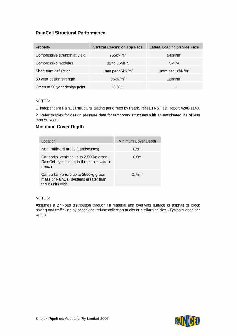
RainCell Structural Performance Property Vertical Loading on Top Face Lateral Loading on Side Face
Compressive strength at yield 765kN/m2 94kN/m2
Compressive modulus 12 to 16MPa 5MPa
Short term deflection 1mm per 45kN/m2 1mm per 10kN/m2
50 year design strength 96kN/m2 12kN/m2
Creep at 50 year design point 0.8% -
NOTES:
1. Independent RainCell structural testing performed by PearlStreet ETRS Test Report 4208-1140.
2. Refer to Iplex for design pressure data for temporary structures with an anticipated life of less than 50 years.
Minimum Cover Depth
Location Minimum Cover Depth
Non-trafficked areas (Landscapes) 0.5m
Car parks, vehicles up to 2,500kg gross. RainCell systems up to three units wide in trench
0.6m
Car parks, vehicle up to 2500kg gross mass or RainCell systems greater than three units wide
0.75m
NOTES:
Assumes a 27º-load distribution through fill material and overlying surface of asphalt or block paving and trafficking by occasional refuse collection trucks or similar vehicles. (Typically once per week)
© Iplex Pipelines Australia Pty Limited 2007
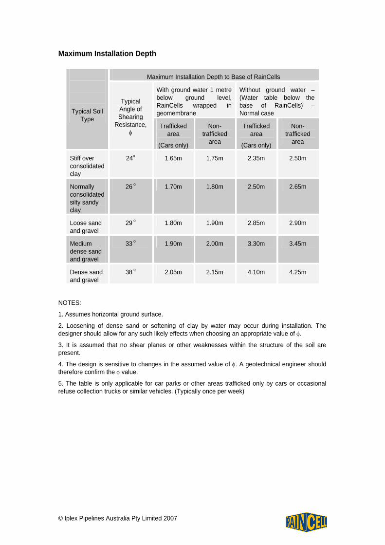
Maximum Installation Depth
Maximum Installation Depth to Base of RainCells
With ground water 1 metre below ground level, RainCells wrapped in geomembrane
Without ground water – (Water table below the base of RainCells) – Normal case
Typical Soil Type
Typical Angle of Shearing
Resistance, φ
Trafficked area
(Cars only)
Non-trafficked
area
Trafficked area
(Cars only)
Non-trafficked
area
Stiff over consolidated clay
24o 1.65m 1.75m 2.35m 2.50m
Normally consolidated silty sandy clay
26 o 1.70m 1.80m 2.50m 2.65m
Loose sand and gravel
29 o 1.80m 1.90m 2.85m 2.90m
Medium dense sand and gravel
33 o 1.90m 2.00m 3.30m 3.45m
Dense sand and gravel
38 o 2.05m 2.15m 4.10m 4.25m
NOTES:
1. Assumes horizontal ground surface.
2. Loosening of dense sand or softening of clay by water may occur during installation. The designer should allow for any such likely effects when choosing an appropriate value of φ.
3. It is assumed that no shear planes or other weaknesses within the structure of the soil are present.
4. The design is sensitive to changes in the assumed value of φ. A geotechnical engineer should therefore confirm the φ value.
5. The table is only applicable for car parks or other areas trafficked only by cars or occasional refuse collection trucks or similar vehicles. (Typically once per week)
© Iplex Pipelines Australia Pty Limited 2007
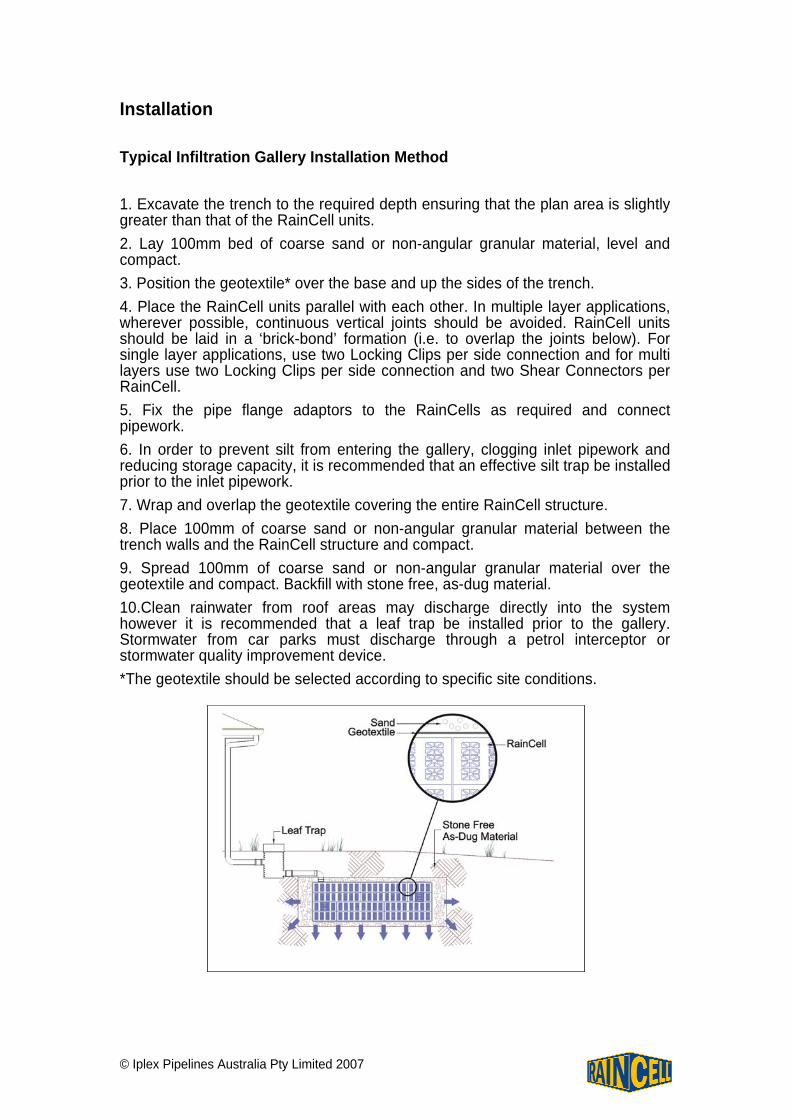
Installation Typical Infiltration Gallery Installation Method 1. Excavate the trench to the required depth ensuring that the plan area is slightly greater than that of the RainCell units. 2. Lay 100mm bed of coarse sand or non-angular granular material, level and compact. 3. Position the geotextile* over the base and up the sides of the trench. 4. Place the RainCell units parallel with each other. In multiple layer applications, wherever possible, continuous vertical joints should be avoided. RainCell units should be laid in a ‘brick-bond’ formation (i.e. to overlap the joints below). For single layer applications, use two Locking Clips per side connection and for multi layers use two Locking Clips per side connection and two Shear Connectors per RainCell. 5. Fix the pipe flange adaptors to the RainCells as required and connect pipework. 6. In order to prevent silt from entering the gallery, clogging inlet pipework and reducing storage capacity, it is recommended that an effective silt trap be installed prior to the inlet pipework. 7. Wrap and overlap the geotextile covering the entire RainCell structure. 8. Place 100mm of coarse sand or non-angular granular material between the trench walls and the RainCell structure and compact. 9. Spread 100mm of coarse sand or non-angular granular material over the geotextile and compact. Backfill with stone free, as-dug material. 10.Clean rainwater from roof areas may discharge directly into the system however it is recommended that a leaf trap be installed prior to the gallery. Stormwater from car parks must discharge through a petrol interceptor or stormwater quality improvement device. *The geotextile should be selected according to specific site conditions.
© Iplex Pipelines Australia Pty Limited 2007
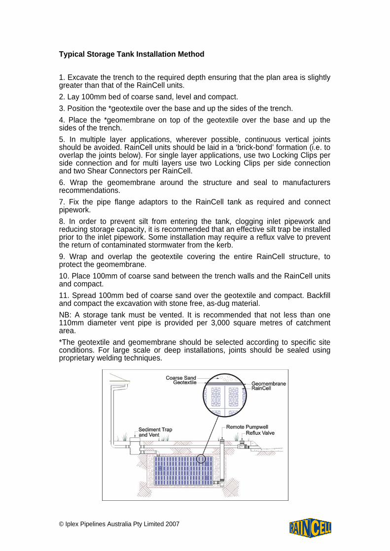
Typical Storage Tank Installation Method 1. Excavate the trench to the required depth ensuring that the plan area is slightly greater than that of the RainCell units. 2. Lay 100mm bed of coarse sand, level and compact. 3. Position the *geotextile over the base and up the sides of the trench. 4. Place the *geomembrane on top of the geotextile over the base and up the sides of the trench. 5. In multiple layer applications, wherever possible, continuous vertical joints should be avoided. RainCell units should be laid in a ‘brick-bond’ formation (i.e. to overlap the joints below). For single layer applications, use two Locking Clips per side connection and for multi layers use two Locking Clips per side connection and two Shear Connectors per RainCell. 6. Wrap the geomembrane around the structure and seal to manufacturers recommendations. 7. Fix the pipe flange adaptors to the RainCell tank as required and connect pipework. 8. In order to prevent silt from entering the tank, clogging inlet pipework and reducing storage capacity, it is recommended that an effective silt trap be installed prior to the inlet pipework. Some installation may require a reflux valve to prevent the return of contaminated stormwater from the kerb. 9. Wrap and overlap the geotextile covering the entire RainCell structure, to protect the geomembrane. 10. Place 100mm of coarse sand between the trench walls and the RainCell units and compact. 11. Spread 100mm bed of coarse sand over the geotextile and compact. Backfill and compact the excavation with stone free, as-dug material. NB: A storage tank must be vented. It is recommended that not less than one 110mm diameter vent pipe is provided per 3,000 square metres of catchment area. *The geotextile and geomembrane should be selected according to specific site conditions. For large scale or deep installations, joints should be sealed using proprietary welding techniques.
© Iplex Pipelines Australia Pty Limited 2007
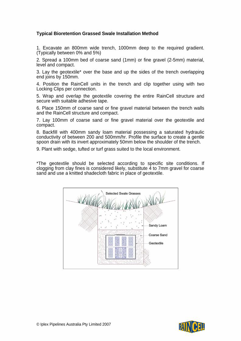
Typical Bioretention Grassed Swale Installation Method 1. Excavate an 800mm wide trench, 1000mm deep to the required gradient. (Typically between 0% and 5%) 2. Spread a 100mm bed of coarse sand (1mm) or fine gravel (2-5mm) material, level and compact. 3. Lay the geotextile* over the base and up the sides of the trench overlapping end joins by 150mm. 4. Position the RainCell units in the trench and clip together using with two Locking Clips per connection. 5. Wrap and overlap the geotextile covering the entire RainCell structure and secure with suitable adhesive tape. 6. Place 150mm of coarse sand or fine gravel material between the trench walls and the RainCell structure and compact. 7. Lay 100mm of coarse sand or fine gravel material over the geotextile and compact. 8. Backfill with 400mm sandy loam material possessing a saturated hydraulic conductivity of between 200 and 500mm/hr. Profile the surface to create a gentle spoon drain with its invert approximately 50mm below the shoulder of the trench. 9. Plant with sedge, tufted or turf grass suited to the local environment. *The geotextile should be selected according to specific site conditions. If clogging from clay fines is considered likely, substitute 4 to 7mm gravel for coarse sand and use a knitted shadecloth fabric in place of geotextile.
© Iplex Pipelines Australia Pty Limited 2007
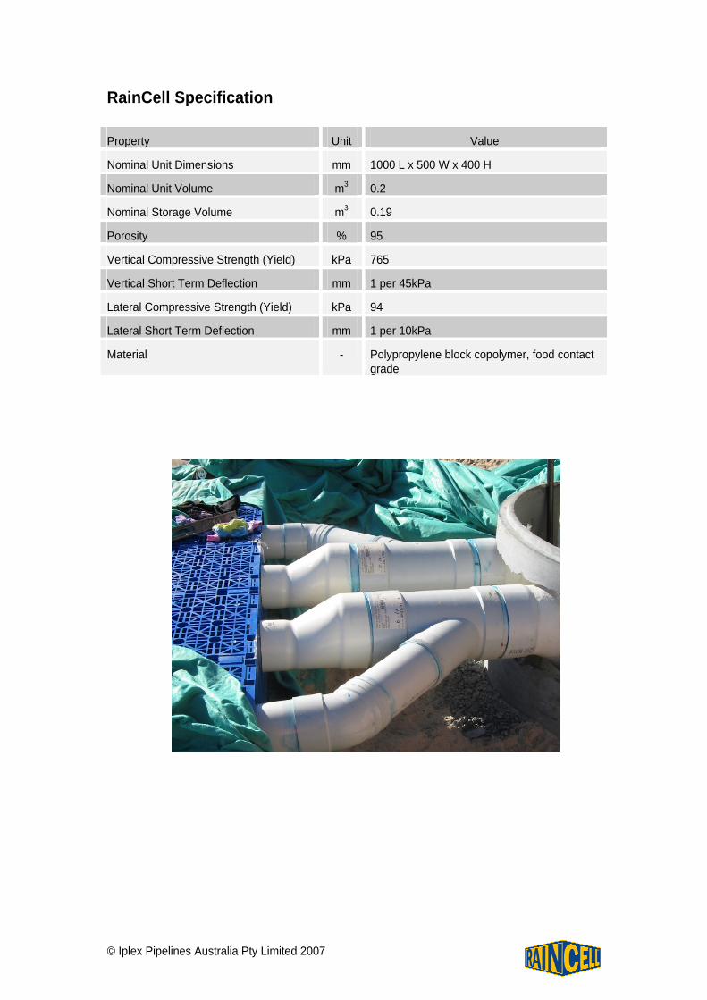
RainCell Specification Property Unit Value
Nominal Unit Dimensions mm 1000 L x 500 W x 400 H
Nominal Unit Volume m3 0.2
Nominal Storage Volume m3 0.19
Porosity % 95
Vertical Compressive Strength (Yield) kPa 765
Vertical Short Term Deflection mm 1 per 45kPa
Lateral Compressive Strength (Yield) kPa 94
Lateral Short Term Deflection mm 1 per 10kPa
Material - Polypropylene block copolymer, food contact grade