engineering change notice 662709 ea - digital library/67531/metadc... · engineering change notice...
TRANSCRIPT

P a i n 1 o t L ENGINEERING CHANGE NOTICE ...................................... 662709
EA A9/R
'. ECN Category (mark one)
Supplemental 0 DirectRevision [XI
0 Change ECN
Standby
SuDersedure 0
Temporary 0
3a. Description of Change 13b. Design Baseline Document? 0 Yes [XI No
3. Originator's Name, Organization, MSIN, and Telephone No.
TM Greager, TRU waste Program O Y e s N N o 11/15/00 T4-05, 376-4344 6. Project TitlelNo.Mlork Order NO. 7. 8ldg.lSys.lFac. No. 8. Approval Designator
4. USQ Required? 5. Date
TRU Project N/A Q 9. Document Numbers Changed by this ECN (includes I O . Related ECN No(s). 11. Related PO No.
sheet no. and rev.)
iNF-2599, Final Hanford Site Transuranic Waste Characterization Quality Assurance Project ?lan is being revised in its entirety to incorporate modifications and clarifications to the iIPP Permit.
CancelNoid 0
0 Yes (fill out Blk. 12b)
No NA Blks. 12b. /2c, 12d)
2a. Modification Work
HNF-2599, Rev. 2A N/A N/A 12b. Work Package No.
N/A
12c. Modification Work Completed 12d. Restored to Ori inal Condition (Temp. or Standby ECds only)
N/A N/A Design AuthorityICo Engineer Signature & Design AuthorityICo Engineer Signature &
B i te B i te
Document is being revised in its entirety Environmental
Facility Deactivation
4a. Justification (mark one)
Criteria Change 0 ~~~i~~ improvement 0
As-Found
Facilitate Const.
:ontrolled Distribution
A-7900-013-2 (10/97)
14b. Justifcation Details
Design verification not required

.I I
Page 2 of 2 1 6 6 2 7 0 9 ENGINEERING CHANGE NOTICE
6. Design Verification 17. Cost Impact Required ENGINEERING CONSTRUCTION
0 Yes Additional 0 $ N / A Additional 0 $ N / A
18. Schedule Impact (days)
Improvement 0 N/A
[XI No I Savings $ N / A Savings 0 $ N / A
SDDIDD
Functional Design Criteria
Operating Specification
Criticality Specification
Conceptual Design Report
Equipment Spec.
Const. Spec.
Procurement Spec.
Vendor Information
OM Manual
FSAWSAR
Safety Equipment List
Radiation Work Permit
Environmental Impact Statement
Environmental Report
Environmental Permit
Delay 0 N / A
SeismidStress Analysis
StresslDesign Report
Interface Control Drawing
Calibration Procedure
Installation Procedure
Maintenance Procedure
Engineering Procedure
Operating Instruction
Operating Procedure
Operational Safety Requirement
IEFD Drawing
Cell Arrangement Drawing
Essential Material Specification
Fac. Proc. Samp. Schedule
Inspection Plan
Inventory Adjustment Request
Tank Calibration Manual 0 Health Physics Procedure 0 Spares Multiple Unit Listing 0
Component Index 0 ASME Coded Item
Computer Software 0 Electric Circuit Schedule 0 ICRS Procedure 0
Process Flow Chart 0 Purchase Requisition 0 Tickler File 0 N / A [XI
0
Test ProceduresISpecification 0
Human Factor Consideration 0
Process Control ManualIPlan 0
0 Otner AHecled Documents (hOTE DocLmenls steo oe.ow u, not ne ievisw oy tn s ECh ) Sognatures oe ow no cate tnal tne s gning organ Lalion nas Dean notitlea of other aHecte0 docJmenls Islea oe ow
Document NumberIRevision Document NumberlRevision Document NumberIRevision
None
1. Approvals Signature Date
Design Authority
Cog. Eng.
Cog. Mgr. 6 [y20pr" QA
Safety \I Environ.
Other
Signature Date
Design Agent
PE
QA
Safety
Design
Environ.
Other
Signature or a Control Number that tracks the Approval Signature
ADDITIONAL

HNF-2599 Revision 3
Copy No. -
Final Hanford Site Transuranic Waste Characterization Quality Assurance Project Plan
Prepared for the US. Department of Energy Assistant Secretary for Environmental Management Project Hanford Management Contractor for the US. Depaltment of Energy under Contract DE-AC06-96RL13200
P.O. Box 1000 Richland, Washington
Fluor Hanford
Approved for public release; further dissemination unlimited
-. - _I__.
HNF-2599 Revision 3
ECN 662709 Copy No. -
Final Hanford Site Transuranic Waste Characterization Quality Assurance Project Plan
Document Type: RPT
TM Greager Fluor Hanford
Registered Trademarks:
Division: WM
** SUMMA is a registered trademark of Moietrics, Inc. Cleveland, OH. *' Teflon is a registered trademark of El dupont de Nemours & Co.. Wilmington , DE, ** VCR is a registered trademark of Cajon, Co., Salon, OH.
Date Published
November 2000
Prepared for the U S . Department of Energy Assistant Secretary for Environmental Management Project Hanford Management Contractor for the US. Department of Energy under Contract DE-AC06-96RLi3200
Fluor Hanford P.O. Box 1000 Richland, W a s h i n g t o n
Release Approval Release Stamp
Approved for public release; further dissemination unlimited
~~~~~~~~ ~~~~
~ ~.

HNF-2599 Revision 3
ECN-662709
LEGAL DISCLAIMER Tnis report was preparea as an accoLnt of wow sponsorea oy an a(Iencv of the Un led Slates Government heither the Ln.tia Slates Government nor any agency thereof. nor any of their emp oyees nor any of lneir contractors SJccontractors or tne r emp oyees, makes any warranty, express or imp1 ed or assdrnes any tega liab; ty or reswns'o I ty lor tne accLracy. completeness, or any lniro party s Lse or the resLlls of sLcn &e 01 any nformation. apparatLs. product. or process o sc osea or represents tnat its ~ s e WOLIO not ,nfringe private y ownea rights. Reference nerein to any specilic c0mmerc.a proaxt, process, or service oy trade name traoemark. manJlaclJrer. or otherw;se. noes not necessar; y constitJe or tmp y ,IS enoorsement. recornmenoation. or favoring oy tne Un.lea Stales Government or any agency tnereol of 1s contractors or sGoconlraclors. Tne # eus an0 op nions of abtnors expressed here n a0 not necessar y state or ref ect tnose of the Jn.led Slates Government or any agency inereof
This report has been reproduced from the best available copy.
Printed in the Unitsd Statas 01 Amsflcca
Total Pages: \ 8 A

RECORD OF REVISION
(3) Revision
0
I HNF-2599
Authorized for Release
( 5 ) Cog. Engr. I (6) Cog. Mgr. Date (4) Description of Change - Replace, Add, and Delete Pages
(7) Initial release per EDT-625620 on 12/21/98
I Page 1
1
2
Complete revision per ECN-651732 on 09/09/99
Complete revision per ECN-655109 on 12/14/99
2 A
RS 3
Page change for HNF-2599 on 01/05/2000 Replace pages 75, 76, 91 and 92 per ECN-655112 Complete revision per ECN-662709 on 11/17/2000 TM Greager - - /l/27/00 -..d& -
lff2&a ' -
A-7320.005 (10/97)

HANFORD SITE TRANSURANIC WASTE CHARACTERIZATION
QUALITY ASSURANCE PROJECT PLAN
HNF-2599 I REV 3
November 1,2000
HNF-2599, REV 3 Page 1 of 178 November 1,2000 HANFORD SITE TRANSURANIC WASTE CHARACTERIZATION
QUALITY ASSURANCE PROJECT PLAN

HANFORD SITE T R A N S W C WASTE CHAXZACTERIZATION
QUALITY ASSURANCE PROJECT PLAN
6 REV 3
November 1,2000
Approved by:
Approved by. - T e d Leader, National TRU Waste Program
Sit4 Quality Assurance Officer jL? me, , L, h --p*
~ ~ ~ - 2 5 9 9 , REV 3 Page 2 of 178 November 1,2000 AANFORD SITE TRANSURANIC WASTE CHARACTERIZATION
QUALITY ASSURANCE PROJECT PLAN

HNF.2599. REV 3 Page 3 of 178 November 1. 2000 HANFORD SITE TRANSURANIC WASTE CHARACTERIZATION
QUALITY ASSURANCE PROJECT PLAN
TABLE O F CONTENTS TABLE OF CONTENTS ............................................................................................................. 3 A A-1 A-2 A-3 A-4 A-5 B B-1 B-2 B-3 B-4 B1-1
INTRODUCTION ............................................................................................................... 5
Hazardous Constituents ..................................................................................................... 6 Waste Characterization ...................................................................................................... 7 Quality Assurance Project Plan ......................................................................................... 7 Project Organization .......................................................................................................... 8 TRU PROJECT HIGHLIGHTS ..................................................................................... 16
Waste Parameters ............................................................................................................. 19 Waste Characterization Methods .................................................................................... 19 Data Verification and Quality Assurance ....................................................................... 28
Headspace-Gas Sampling .............................................................................................. 49
Waste Analysis Plan ............................................................................................................ 5
Identification of TRU Waste to be Shipped to the WIPP Facility ................................ 16
B1-2 Sampling of Homogenous Solids and SoiVGravel ........................................................... 58 B1-3 Radiography ................................................................................................................... 66 B1-4 Custody of Samples ....................................................................................................... 72 B1-5 Sample Packing and Shipping .......................................................................................... 74 B2 STATISTICAL METHODS USED IN SAMPLING AND ANALYSIS ...................... 87 B2-1 Approach for Statistically Selecting Waste Containers for Visual Examination .... 87 B2-2 I Sauplkng ......................... 90 B2-3 Upper Confidence Limits for Statistied Sampling ......................................................... 94 B2-4 Control Charting for Newly Generated Waste Stream Sampling ................................. 95 B3 SAMPLING AND ANALYTICAL METHODS ...................................................................... 99 B3-1 Validation Methods ....................................................................................................... 99 B3-2 Headspace Gas Sampling ................................................................................................ 104 B3-3 Sampling of Homogeneous Solids and Soil .................................................................... 106 B3-4 Radiography ..................................................................................................................... 109 B3-5 Headspace Gas Volatile Organic Compound Analysis ................................................ 110 B3-6 Total Volatile Organic Compound Analysis ................................................................. 112 B3-7 Total Semivolatile Organic Compound Analysis .......................................................... 114 B3-8 Total Metal Analysis ........................................................................................................ 116
B3-10 Data Review. Validation. and Verification Requirements ....................................... 119 B3-11 Reconciliation with Data Quality Objectives .............................................................. 127 B3-12 Data Reporting Requirements ...................................................................................... 129
B3-14 Special Training Requirements and Certifications .................................................... 132 B3-15 Changes to WAP-Related Plans o r Procedures ........................................................ 133 B4 B4-1 Introduction ................................................................................................................. 155 B4-2 AK Documentation ...................................................................................................... 155 B4-3 AK Training, Procedures and Other Requirements .................................................... 158 B4-4 Additional Final Confirmation of AK at the WIPP Facility ........................................ 166 B5 B5-1 Quality Assurance Project Plans .............................................. __ _.. ......_-........ 172 B5-2 WcmnmntRniew, Approval. and Control ......................... .-.. __ .........._-.. 173
Approach for Selecting Waste Containas for St
QUALITY ASSURANCE OBJECTIVES FOR WASTE CHARACTERIZATION
B3-9 Acceptable Knowledge ..................................................................................................... 118
B3-13 Nonconformances ........................................................................................................... 131
WASTE CHARACTERIZATION USING ACCEPTABLE KNOWLEDGE .......... 155
QUALITY ASSURANCE PROJECT PLAN REQUIREMENTS ............................. 172

HNF.2599. REV 3 Page 4 of 178 November 1. 2000 HANFORD SITE TRANSURANIC WASTE CHARACTERIZATION
QUALITY ASSURANCE PROJECT PLAN
B6 B6-1 Introduction ................................................................................................................. 174 B6-2 Audit Procedures ......................................................................................................... 175 B6-3 Audit Position Functions ............................................................................................. 175 B6-4 Audit Conduct .............................................................................................................. 175 C LIST OF REFERENCES .............................................................................................. 177
AUDIT AND SURVEILLANCE PROGRAM ............................................................. 174
... . ~

HNF-2599, REV 3 Page 5 of 178 November 1,2000 HANFORD SITE TRANSURANIC WASTE CHARACTERIZATION
QUALITY ASSURANCE PROJECT PLAN
A INTRODUCTION
A-1 Waste Analysis Plan
The Quality Assurance Project Plan (QAPjP) has been prepared for waste characterization activities to be conducted by the Transuranic (TRU) Project at the Hanford Site to meet requirements set forth in the Waste Isolation Pilot Plan (WIPP) Hazardous Waste Facility Permit, 4890139088-TSDF, Attachment B, including Attachments B1 through B6 (WAP) (DOE, 1999a). The QAPjP describes the waste characterization requirements and includes test methods, details of planned waste sampling and analysis, and a description of the waste characterization and verification process. In addition, the QAPjP includes a description of the quality assurance/quality control (QNQC) requirements for the waste characterization program. Before TRU waste is shipped to the WIPP site by the TRU Project, all applicable requirements of the QAPjP shall be implemented. Additional requirements necessary for transportation to waste disposal at WIPP can be found in the “Quality Assurance Program Document” (DOE 1999b) and HNF-2600, “Hanford Site Transuranic Waste Certification Plan.”
TRU mixed waste contains both TRU radioactive and hazardous components, as defined in the WLPP-WAP. The waste is designated and separately packaged as either contact-handled (CH) or remote-handled (RH), based on the radiological dose rate at the surface of the waste
I container. RH TRU wastes are not currently shipped to the WIPP facility.
Some TRU waste is retrievably stored at the Hanford Site. Additional TRU waste will be generated and packaged into containers in the future. Retrievably stored waste is defined as TRU waste generated after 1970 and before New Mexico Environmental Department (NMED) notifies WIPP, by approval of the final Hanford Site audit report, that the characterization requirements of the WAP at the Hanford Site TRU Project have been implemented or waste that is not generated under the control of the approved waste characterization program. Newly generated waste is defined as TRU waste generated after NMED approves the final audit report that is under the control of the approved waste characterization program. Retrievably stored TRU waste will be characterized on an ongoing basis as the waste is retrieved. Newly generated TRU waste shall be characterized as it is generated. Waste characterization requirements for retrievably stored and newly generated TRU wastes differ, as is discussed in Sections B-3d(l) and B-3d(2).
Characterization requirements for individual containers of TRU waste are specified on a waste stream basis. A waste stream is defined as waste material generated from a single process or from an activity that is similar in material, physical form, and hazardous constituents. Waste streams are grouped by Waste Matrix Code Groups related to the physical and chemical properties of the waste. The TRU Project shall use the characterization techniques described in
Matrix Code Groups are solidified inorganics, solidified organics, salt waste, soils, leadcadmium metal, inorganic nonmetal waste, combustible waste, graphite, filters, heterogeneous debris waste, and uncategorized metal. Waste Matrix Code Groups can be grouped into three Summary Category Groups: Homogenous Solids (Summary Category S3000), Soil/Gravel (Summary Category S4000), and Debris Waste (Summary Category SSOOO).
I the QAPjP to assign appropriate Waste Matrix Code Groups for WIPP disposal. The Waste

HNF-2599, REV 3 Page 6 of 178 November 1,2000 HANFORD SITE TRANSURANIC WASTE CHARACTERIZATION
QUALITY ASSURANCE PROJECT PLAN
TRU wastes are initially categorized into the three broad Summary Category Groups that are related to the final physical form of the wastes. Waste characterization methods for these
described below. I groups are specified separately in Section B-3 of the QAPjP. Each of the three groups is
0 S3000 - Homogeneous Solids Homogenous solids, or solid process residues, are defined as solid materials, excluding soil, that do not meet the criteria for classification as debris. Included in the series of solid process residues are inorganic process residues, inorganic sludges, salt waste, and pyrochemical salt waste. Other waste streams are included in this Summary Category Group based on the specific waste stream types and final waste form. This Summary Category Group is expected to contain toxic metals or spent solvents. This category includes wastes that are at least 50 percent by volume solid process residues.
0 S4000 - Soils/Gravel This Summary Category Group includes S4000 waste streams that are at least 50 percent by volume soiUgrave1. This Summary Category Group is expected to contain toxic metals. Soils/gravel are further categorized by the amount of debris included in the matrix.
0 S5000 - Debris Wastes This Summary Category Group includes heterogenous waste that is at least 50 percent by volume materials that meet the criteria specified in the WIPP-WAP. Debris means solid material exceeding a 2.36 inch (in.) (60 millimeter) particle size that is intended for disposal and that is:
a manufactured object, or plant or animal matter, or
0 natural geologic material.
Particles smaller than 2.36 inches in size may be considered debris if the debris is a manufactured object and if it is not a particle of S3000 or S4000 material.
If a waste does not include at least 50 percent of any given category by volume, characterization shall be performed using the waste characterization process required for the category constituting the greatest volume of waste for that waste stream (see Section B-3d).
A-2 Hazardous Constituents
The most common hazardous constituents in the TRU waste to be shipped to the W P P facility consist of the following:
0
0
8
DO04 through DO1 1 metals Halogenated listed volatile organic compounds (F001 through F005) Nonhalogenated volatile organic compounds such as xylene and methanol.
HNF-2599, REV 3 Page 7 of 178 November 1,2000 HANFORD SITE TRANSURANIC WASTE CHARACTERIZATION
QUALITY ASSURANCE PROJECT PLAN
A-3 Waste Characterization
A-3a Waste Characterization Activities
All waste characterization activities specified in the QAPjP shall be carried out under the direction of the TRU Project. The WIPP Site will audit the TRU Project waste characterization programs and activities as described in Section 8-3. Waste characterization activities include the following, although not all these techniques will be used on each container, as discussed in Section B-3:
I
. Radiography, which is an x-ray technique to determine physical contents of
Visual examination (VE) of opened containers as an alternative way to determine
Headspace gas sampling to determine volatile organic compound (VOC) content
Sampling and analysis of waste forms that are homogeneous and can be
containers.
. their physical contents or to verify radiography results.
. of gases in the void volume of the containers.
. representatively sampled to determine concentrations of hazardous waste constituents and toxicity characteristic contaminants of waste in containers.
. Compilation of acceptable knowledge (AK) documentation into an auditable record.
A-3b Waste Characterization Documentation
Once the required waste characterization is complete, the TRU Project will complete a Waste Stream Profile Form (WSPF) to document the results of the characterization activities (see Section B-ld). The data summary reports, waste stream characterization summary report(s), and WSPFs resulting from waste characterization activities shall be transmitted to WIPP, reviewed
I for completeness, and screened for acceptance prior to shipment of any TRU waste to WIPP by the TRU Project (see Section B-4). Only TRU waste that has been characterized in accordance
I with the QAPjP and that meets the Treatment, Storage, and Disposal Facility Waste Acceptance Criteria (WIPP-WAC) specified in the Waste Acceptance Plan (WAP) will be accepted at the WIPP facility
A-4 Quality Assurance Project Plan
A-4a The WPP-WAP requires each U S . Department of Energy (DOE) site that characterizes waste to be sent to WIPP to develop and implement a QAPjP that addresses the applicable requirements specified in the WAP (DOE 1999a). The QAPjP describes the implementation of WAP requirements and complies with the QNQC requirements for waste Characterization.
I

HNF-2599, REV 3 Page 8 of 178 November 1,2000 HANFORD SITE TRANSURANIC WASTE CHARACTERIZATION
QUALITY ASSURANCE PROJECT PLAN
I A-4b The QAPjP establishes requirements to be met by the TRU Project organization in characterizing waste for shipment to WIPP. These requirements are implemented by the various TRU Project facilities supporting the TRU Waste Project using approved implementing procedures. The QAPjP provides QA requirements applicable to the TRU Project activities as defined in this document.
Implementing procedures are developed for all activities affecting TRU Project quality. These procedures are developed in accordance with WMH-400, Section 2.1.2,“TRU Operating Procedure Preparation and Approval” (see Table A-l), WMH-400, Section 2.1.3 “TRU Administrative Procedure Preparation and Approval” (see Table A-1), and WMH-400, Section 2.1.6, “TRU Analytical Procedure Process” (see Table A-I), which describe the organization and format for TRU Project procedures. The most recent revision of these procedures is available electronically on a network drive and/or web page. Personnel ensure that they are working to the most up-to-date version of the applicable procedure by accessing the electronic version via the TRU Project shared drive document system or web page or by comparing their hard copy of the procedure to the electronic version. Project QA requirements for procedures are described in WMH-400, Sections 2.1.2,2.1.3, and 2.1.6. Procedures include examples of data forms (e.g., reports, forms, and data validation checklists), as appropriate. Data
review and approval requirements are specified for each procedure. Facility QA procedures for TRU Project activities (e.g., records management) are equivalent to project QA plans and procedures. Table A-l provides a list of facility procedures that implement the WIF’P characterization and certification requirements of the QAPjP and Hanford Site certification plan requirements. The list also includes the anticipated names and document numbers of procedures that will be prepared in the future to address requirements for activities not yet implemented at Hanford. Additional procedures may be prepared to implement the requirements of the QAPjF as necessary.
A-4c
I I
I forms used in the TRU Project are available on the TRU Project shared drive. Internal
I I
A-5 Project Organization
A-5a Site Project Manager
The Site Project Manager (SPM) provides overall management and coordination for the characterization of TRU waste at the Hanford Site. The SPM statistically selects waste containers for solidified waste sampling and visual examination (VE); validates all sampling, testing, and analytical data; and transmits data to the Carlsbad Area Office (CAO).
The SPM is the principal point of contact with DOE for technical activities associated with TRU waste. The SPM provides programmatic support for TRU Project waste organizations involved in TRU waste storage, characterization, certification, and transportation activities. The SPM coordinates with the TRU Waste Certification Official (WCO) and TRU site Transportation Certification Official (TCO) and oversees TRU Project activities to ensure that TRU waste is characterized and certified compliant with WIPP requirements. Specific project responsibilities assigned to the SPM include the following:
Reviewing and approving the site QAPjP and waste certification plan.

HNF-2599, REV 3 Page 9 of 178 November 1,2000 HANFORD SITE TRANSURANIC WASTE CHARACTERIZATION
QUALITY ASSURANCE PROJECT PLAN
0 Ensuring that the TRU Project compliance plan for the TRAMPAC-I1 Authorized Methods for Payload Control (TRAMPAC) and associated documents are revised, reviewed, approved, and implemented as necessary to maintain authorization for shipping TRU waste to WIPP.
Ensuring project personnel receive appropriate training and orientation
Selecting, prioritizing, and tracking waste to be sampled and analyzed.
Validating and verifying project-level analytical data
Reconciling analytical data with data quality objectives (DQOs).
0
0
0
0
0 Certifying WSPF data.
0 Assigning of USEPA hazardous waste numbers and Washington State-specific dangerous waste codes.
Submitting QA/QC reports to DOE field offices
Transmitting testing, sampling, and analytical data to CAO.
Assisting the TRU Site QA Officer (SQAO) in defining and standardizing project assessment criteria and preparing responses to deficiency reports, such as corrective action reports (CARS), generated by CAO internal or other external assessment organizations.
Stopping certification activities if problems affecting the quality of certification processes or work products exist.
Notifying personnel of nonconfonnances in accordance with WMH-400, Section 1.3.2, “TRU Nonconforming Item Reporting and Control,” and WMH-400, Section 1.3.3, “TRU Corrective Action Reporting and Control.”
I
0
0
0
0
0
The SPM may delegate any of these activities to another individual; however, the SPM retains responsibility for ensuring that project requirements are met.
A-5c Site Quality Assurance Officer
The SQAO provides QA oversight and planning for TRU Project waste characterization and certification and oversees the implementation of the QAPjP and the QA requirements of the waste certification plan. The SQAO’s general responsibilities include the following:
Reviewing and approving the site QAPjP and waste certification plan
Verifying QNQC requirements have been implemented.
0
0

HNF-2599, REV 3 Page 10 of 178 November 1,2000 HANFORD SITE TRANSURANIC WASTE CHARACTERIZATION
QUALITY ASSURANCE PROJECT PLAN
Assessing laboratory/testing facilities.
0
Coordinating internal and external audits and assessments to verify compliance.
Tracking and evaluating trends in compliance with QA objectives (QAOs) established in the QAPjP by performing the following:
- ensuring that testing, sampling, and analytical facilities are assessed ensuring that nonconformance reports (NCRs) or CARs that affect project
verifying corrective actions have been taken to resolve nonconformances validating and verifying analytical data at the project level verifying analytical data QA documentation
.
activities are prepared, when appropriate tracking and trending nonconformances
- - .
submitting QNQC reports to the SPM, as needed
Providing day-to-day guidance to the TRU Project staff on quality related matters.
Coordinating responses to deficiency reports (e.g., CARs) generated by CAO or other external assessment organizations.
Providing QA oversight for data package assembly and interface with the WIPP Waste Information System (WWIS).
Stopping program activities if problems affecting the quality of the certification processes or work products exist.
Summarizing all relevant information on the QNQC activities during the period in a semiannual report. Submitting the report to the SPM. The report shall include the following applicable information:
0
0
0 I
significant QNQC problems, recommended solutions, and corrective actions taken
assessment of QC data gathered over the period, the frequency of analyses repeated because of unacceptable QA performance, the reason for unacceptable performance (if known), and corrective actions taken
- discussion of whether the QA objectives have been met, and any resulting impact on decision making
limitations of the use of the measurement data
. status of performance demonstration program (PDP) sample results
results of audits, assessments and surveillances.
HNF-2599, REV 3 Page 11 of 178 November 1,2000 HANFORD SITE TRANSURANIC WASTE CHARACTERIZATION
QUALITY ASSURANCE PROJECT PLAN
The SQAO may designate one or more individuals to perform the above functional responsibilities but retains ultimate responsibility for assuring compliance with project requirements.
A-5d Site Waste Certification Official (WCO)
The WCO certifies all data and information necessary to document that all TRU waste payload containers prepared for shipment to WIPP meet all specified criteria. The WCO coordinates activities related to waste characterization and works closely with the SQAO to effect QC of the project. Specific duties and responsibilities of the WCO include the following:
I e Certifying that waste packages meet WIPP-WAC requirements
e
e
Interfacing with the SPM, TCO, and SQAO on matters related to certification.
Implementing the following project QA activities:
- reviewing and approving the waste certification plan
ensuring that characterization and certification documents are managed as - QA records in the designated repository
- preparing NCRs and CARs
- documenting corrective actions
coordinating with the SQAO to analyze trends in project nonconformances for certification-related activities
- assisting the SQAO in preparing responses to deficiency reports, such as CARs, generated by CAO or other external assessment organizations.
e Ensuring that all container characterization and certification data entered into the WWIS are accurate.
Stopping certification activities if problems affecting the quality of certification processes or work products exist.
I
e
The WCO may designate one or more individuals to perform these responsibilities but retains ultimate responsibility for ensuring that project requirements are met.
A-5e Site Transportation Certification Official (TCO)
The TCO confirms and verifies that all the necessary information to document TRU waste payload containers prepared for shipment to WIPP meet all specified certification criteria.
I
The TCO ensures that the site-specific TRU waste packaging and transportation activities comply with the TRAMPAC and applicable U.S. Department of Transportation (DOT), rqimments specified in 49 Code of Federal Regulations (CFR)!aw&Nuckear Regulatory
HNF-2599, REV 3 Page 12 of 178 November 1,2000 HANFORD SITE TRANSURANIC WASTE CHARACTEFUZATION
QUALITY ASSURANCE PROJECT PLAN
Commission (NRC) requirements in 10 CFR 71, The TCO verifies payload containers and payload -assemblies and ensures compliance with all packaging and records requirements. The TCO obtains WIPP authority to ship and ensures that all requirements are met before the transportation packaging is released to a carrier for transport. Specific TCO responsibilities include the following:
I Coordinating shipping activities with the originating facility and CAO.
Ensuring that the TRU Project compliance plan for TRAMPAC (Section 4.0 of the waste certification plan) and associated documents are revised, reviewed, approved, and implemented, as necessary, to maintain authorization for offsite shipments of TRU waste.
Interfacing with the originating facility to develop and maintain procedures to load the TRUPACT-I1 in accordance with the TRUPACT-I1 Safety Analysis Report for Packaging ( S A R P ) and WIPP-WAC to ensure that all payloads meet all applicable requirements.
Maintaining TRU Project TRUPACT-I1 Content Codes (TRUCON) in accordance with the TRUCON (DOE 1996), and requesting revisions from CAO, as necessary.
Interfacing with the SPM, WCO, and SQAO on matters related to payload certification and offsite transportation of TRU waste.
Developing and maintaining the packaging QA plan (Section 5.0 of the waste certification plan) as required by the WIPP-WAC.
Reviewing and approving the waste certification plan.
Preparing and signing bills of lading, Uniform Hazardous Waste Manifests (UHWM), and land disposal restriction (LDR) notifications, as appropriate.
Shipping activities related to the TRUPACT-I1 and WIPP waste acceptance include the following:
I
Ensuring compliance with applicable DOT and NRC regulations.
Providing guidance to waste generators to assist their efforts to comply with the TRAMPAC and WIPP-WAC criteria and requirements in implementing procedures affecting characterization, quality assurance, and waste certification.
Ensuring that the proper shipping category, TRUCON codes, and WSPF number are assigned to each container and shipment.
Reviewing all payload data sheets and records to guarantee and document compliance with all packaging and shipping requirements.

HNF-2599, REV 3 Page 13 of 178 November 1,2000 HANFORD SITE TRANSURANIC WASTE CHARACTERIZATION
QUALITY ASSURANCE PROJECT PLAN
0 In conjunction with the WCO, ensuring that all waste containers and shipments are certifiable for transport and that all documentation packages are complete and accurate.
Coordinating the payload container WWIS entries with the data entry personnel and WCO to obtsin approval to ship.
Interfacing with WCO, SPM, and SQAO on matters related to payload container certification and offsite transportation of TRU Waste.
e I
I 0
The TCO may designate one or more individuals to perform these responsibilities but retains ultimate responsibility for ensuring that certification-related project requirements are met.

HNF-2599, REV 3 Page 14 of 178 November 1,2000 HANFORD SITE TRANSURANIC WASTE CHARACTEFUZATION
QUALITY ASSURANCE PROJECT PLAN
Table A-1 IMPLEMENTING PROCEDURES
PROCEDURE NUMBER TITLE WMH-400, Section 1.1.2 TRU Grade Approach (CAO Approval Required) WMH-400, Section 1.2.1 WMH-400, Section 1.2.2 WMH-400, Section 1.2.3 WMH-400, Section 1.3.1 WMH-400, Section 1.3.2 WMH-400, Section 1.3.3 WMH-400, Section 1.4.1 WMH-400, Section 1 S.1 WMH-400, Section 2.1.1 WMH-400, Section 2.1.2 WMH-400, Section 2.1.3 WMH-400, Section 2.1.4 WMH-400, Section 2.1.5 WMH-400, Section 2.1.6 WMH-400, Section 2.3.1 WMH-400, Section 2.3.2 WMH-400, Section 2.3.3 WMH-400, Section 2.4.1 WMH-400, Section 2.4.2 WMH-400, Section 2.4.4 WMH-400, Section 2.4.5 WMH-400, Section 3.1.1 WMH-400, Section 3.1.2 WMH-400, Section 3.2.1 WMH-400, Section 3.2.2 WMH-400, Section 6.1.1 WMH-400, Section 7.1 . I
WMH-400, Section 7.1.3 WMH-400, Section 7.1.4
WMH-400, Section 7.1.5 WMH-400, Section 7.1.6 WMH-400, Section 7.1.7 WMH-400, Section 7.1.8 WMH-400, Section 7.1.9 WMH-400, Section 7.1.10 WMH-400, Section 8.1.1 WMH-400, Section 8.1.8 WMP-350, Section 2.2 WMP-350, Section 2.3 WMP-350, Section 2.4 WMP-350, Section 2.5 WRPI-OP-0503 WRP 1 -0P-052 1 WRP 1 -0P-0522 WWl-OP-0524
TRU Training and Qualification Plan Quality of NDA, NDE, VE and InspectioniTest Personnel Certification of Audit Personnel TRU Corrective Action Management TRU NC Item Reporting and Control TRU Corrective Action Reporting and Control TRU Document Control TRU Records Management TRU Process Control TRU Operating Procedure Preparation and Approval TRU Administrative Procedure Preparation and Approval TRU Item Handling and Storage TRU Transportation Logistics TRU Analytical Procedure Process TRU Procurement Planning TRU Procurement Document Control TRU Control of Purchased Items and Services TRU Inspection Control TRU Test Control TRU Control of Measuring, Testing, and Data Collection Equipment. TRU Identification and Control of Items TRU Management Assessments Quality Assurance Reports to Management TRU Independent Assessment TRU Surveillance Program TRU Software Quality Assurance TRU Waste Characterization Data Quality Objectives Reconciliation and Reporting TRU Waste Repack, VE and Sampling Sampling Design and Data Analysis for RCRA Characterization and VE of Retrievably Stored Transuranic Waste WIPP Waste Information System Data Entry and Reporting TRU Waste Project Level Data Validation and Verification TRU Waste Sample and Waste Container Management Activities TRU Waste Transportation and Disposal Certification Acceptable Knowledge Documentation Management TRU Waste Visual Examination Technique Logkeeping Practices for Headspace Gas Sampling and Analysis Data Management for Headspace Gas Results Calculation of Assay Results Data Management for NDEMDA Results Quality Assurance Objectives for Nondestructive Assay at WRAP GEA Energy and Efftciency Setup and Baseline Establishment Move Drums Throughout the WRAP Facility Receive and Load TRUPACT-I1 Containers Assemble and Stretch Wrap TRUPACT-I1 Payload Helium Leak Test of the TRUPACT-I1 Shippi,ng,Conbiner

HNF-2599, REV 3 Page 15 of 178 November 1,2000 HANFORD SITE TRANSURANIC WASTE CHARACTERIZATION
QUALITY ASSURANCE PROJECT PLAN
PROCEDURE NUMBER TITLE WRP1-OP-0725 TRU Sortine. Glovebox Ooeration WRPI-OP-0726 WRP1-OP-0729 WRP1-OP-0905 WRP1-OP-0906 WRP1-OP-0908 wRP1-OP-0911 WRP1-OP-1225 LA-523410 LA-523-426 LO-080-407 LO-090-450 DO-080-009 ZA-400-301 ZA-400-302 ZA-948-385 20-160-080 FSP-PFP-5-8, Section 16.1 FSP-PFP-5-8, Section 16.2
TRU Loadoit Gloveboxes Operation Visual Examination Imaging PassiveiActive Neutron Assay Operation Gamma Energy Assay Operations Operation of the Drum Nondestructive Examination System Storage and Use of Special Nuclear Material Radiological Support of TRUPACT-I1 Shipping and Receiving Determination of VOCs in HGS Determination of Permanent Gases in HGS Cleaning SUMMA Canisters Sample COC Acceptance and Disposal Obtain HG Samples of TRU Waste Containers SAS Energy and Efficiency Setup and Baseline Determination Calculation of Assay Results NDA Using the Segmented Gamma Scan Assay System (SGSAS) Pipe-N-Go Processing Quality Assurance Objectives for NDA at PFP Data Management for NDA Results

HNF-2599, REV 3 Page 16 of 178 November 1,2000 HANFORD SITE TRANSURANIC WASTE CHARACTERIZATION
QUALITY ASSURANCE PROJECT PLAN
B TRU PROJECT HIGHLIGHTS
B-1
B-la Waste Stream Identification
Identification of TRU Waste to be Shipped to the WIPP Facility
TRU waste destined for shipment to WIPP will be characterized on a waste stream basis. The TRU Project will delineate waste streams using AK, as described in WMH-400, Section 7.1.9, “Acceptable Knowledge Documentation Management” (see Table A-1). Required AK is specified in Section B-3b and B4. If AK for retrievably stored waste does not comply with these requirements, the TRU Project will re-examine (and characterize) the waste in the same manner as newly generated waste.
All of the waste within a waste stream may not be available for sampling and analysis at one time. In these instances, the TRU Project may divide waste streams into waste stream lots based on staging, transportation, or handling issues. Characterization activities will then be undertaken on a waste stream lot basis. A WSPF need not be submitted for subsequent waste stream lots unless warranted by the characterization information. TRU Project personnel
Section 7.1.4, “Sampling Design and Data Analysis for RCRA Characterization and VE of Retrievably Stored Transuranic Waste” (see Table A-1).
B-lb
I randomly select waste containers for VE and/or sampling as described in WMH-400,
Waste Summary Category Groups and Hazardous Waste Accepted at the WIPP Facility
Once a waste stream has been delineated, the TRU Project will assign a Waste Matrix Code to the waste stream based on the physical form of the waste. Waste streams are assigned to one of three broad Summary Category Groups; S3000-Homogeneous Solids, S4000-Soils/Gravel, and S5000-Debris Wastes. These Summary Category Groups are used to determine further characterization requirements.
The TRU Project will only ship TRU waste streams with USEPA hazardous waste codes included on the WIPP Resource Conservation and Recovery Act (RCRA) Part A Permit Application (Permit Attachment 0). Some of the waste may also be identified by Washington State dangerous waste codes. These wastes are acceptable at the WIPP as long as the treatment, storage, and disposal facility (TSDF) WAC are met. The TRU Project will perform characterization of all waste streams as required by the QAPjP. If during the characterization
I process, new USEPA hazardous waste codes are identified, those wastes will not be shipped to the WIPP facility until a permit modification has been approved by WIPP and the NMED.
I
HNF-2599, REV 3 Page 17 of 178 November 1,2000 HANFORD SITE TRANSURANIC WASTE CHARACTERIZATION
QUALITY ASSURANCE PROJECT PLAN
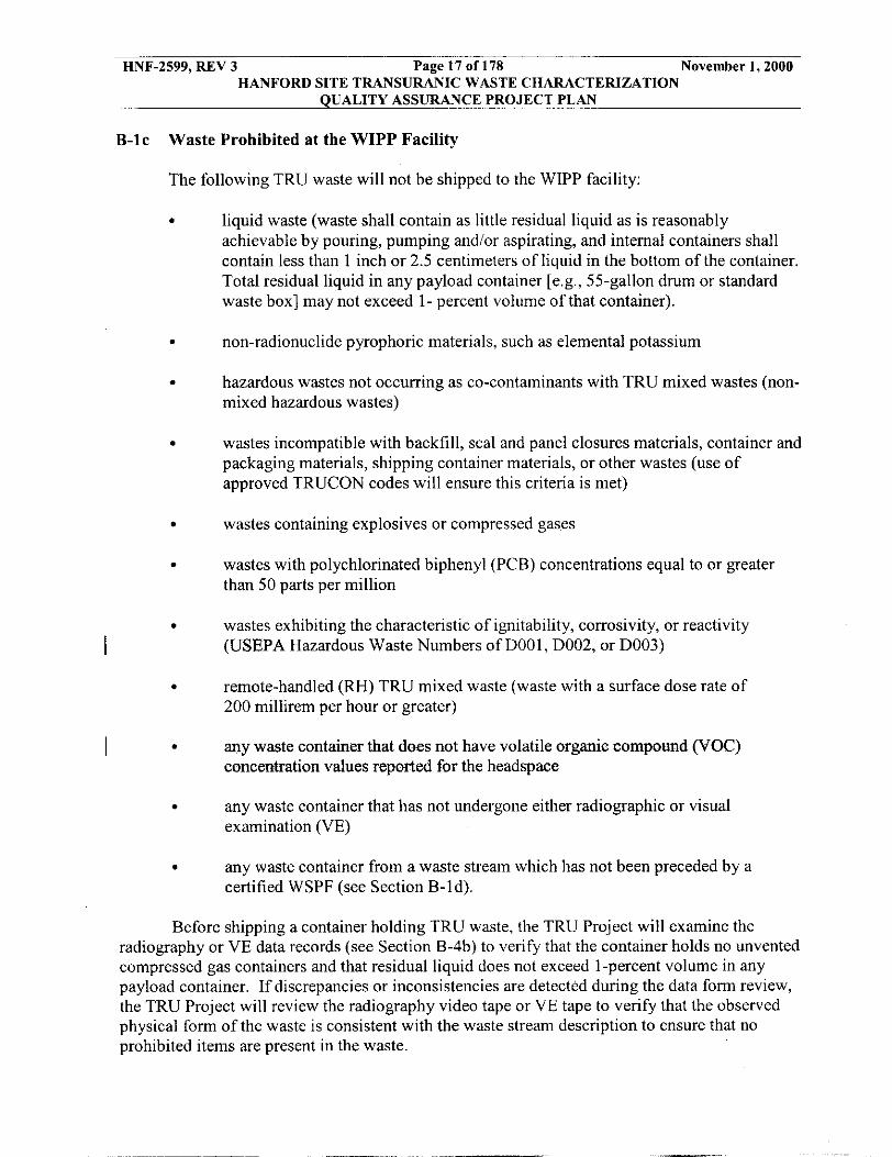
B-lc Waste Prohibited at the WIPP Facility
The following TRU waste will not be shipped to the WIPP facility:
. liquid waste (waste shall contain as little residual liquid as is reasonably achievable by pouring, pumping and/or aspirating, and internal containers shall contain less than 1 inch or 2.5 centimeters of liquid in the bottom of the container. Total residual liquid in any payload container [e.g., 55-gallon drum or standard waste box] may not exceed 1- percent volume of that container).
. non-radionuclide pyrophoric materials, such as elemental potassium
hazardous wastes not occurring as co-contaminants with TRU mixed wastes (non-
wastes incompatible with backfill, seal and panel closures materials, container and
. mixed hazardous wastes)
. packaging materials, shipping container materials, or other wastes (use of approved TRUCON codes will ensure this criteria is met)
. wastes containing explosives or compressed gases
wastes with polychlorinated biphenyl (PCB) concentrations equal to or greater
wastes exhibiting the characteristic of ignitability, corrosivity, or reactivity
remote-handled (RH) TRU mixed waste (waste with a surface dose rate of 200 millirem per hour or greater)
any waste container that does not have volatile organic compound (VOC)
any waste container that has not undergone either radiographic or visual
any waste container from a waste stream which has not been preceded by a
. than 50 parts per million
. I (USEPA Hazardous Waste Numbers of DOOl, D002, or D003)
.
. concentration values reported for the headspace
I
. examination (VE)
. certified WSPF (see Section B-Id).
Before shipping a container holding TRU waste, the TRU Project will examine the radiography or VE data records (see Section B-4b) to verify that the container holds no unvented compressed gas containers and that residual liquid does not exceed 1-percent volume in any payload container. If discrepancies or inconsistencies are detected during the data form review, the TRU Project will review the radiography video tape or VE tape to verify that the observed physical form of the waste is consistent with the waste stream description to ensure that no prohibited items are present in the waste.
HNF-2599, REV 3 Page 18 of 178 November 1,2000 HANFORD SITE TRANSURANIC WASTE CHARACTERIZATION
QUALITY ASSURANCE PROJECT PLAN
Containers are vented through carbon composite particulate filters or filters with equivalent VOC dispersion characteristics, allowing any gases that are generated by radiolytic
I and microbial processes within a waste container to escape. This prevents over pressurization or development of conditions within the container that would lead to the development of ignitable, corrosive, reactive, or other characteristic wastes as described in the waste certification plan.
I
To ensure the integrity of the WIPP facility, waste streams identified to contain incompatible materials or materials incompatible with waste containers will not be shipped to W P P unless they are treated to remove the incompatibility.
The VOC concentrations in the headspace of waste containers have been limited to those which, when averaged on a room basis, will ensure compliance with the performance standards. These limits are presented in Table B-2 as maximum allowable VOC room-averaged headspace concentration limits. There are no maximum allowable headspace gas concentration limits for individual containers. The WIPP will determine VOC room limits and disposal actions if containers exceed the limits stated in Table B-2. Headspace gas analytical results will be transmitted to WIPP in accordance with WMH-400, Section 7.1.5, “WIPP Waste Information System Data Entry and Reporting” (see Table A-1).
B-ld Control of Waste Acceptance
I
Every waste stream shipped to WIPP shall be preceded by a WSPF (see Figure B-1). The required WSPF information and the characterization information summary elements are found in Section B3-12b(l):
The TRU Project wig€ SPF to WIPP for each waste stream prior to its acceptance for disposal. The characterization information summary will be transmitted to WIPP for each waste stream (WMH-400, Section 7.1.5). If continued waste characterization reveals discrepancies &at identify different hazardous waste codes or indicates that the waste belongs to a different waste stream, the waste will be redefined to a separate waste stream and a new WSPF will be submitted.
As stated in the introduction to Attachment B, any time the permittees request additional information concerning a waste stream, the generatodstorage site will provide a waste stream characterization package (Section B3-12b(2)). The option for the permittees to request additional information ensures that the waste being offered for disposal is adequately characterized and accurately described on the WSPF.
Tables B-1, B-3, B-4 and B-5 provide the parameters of interest for the various constituent groupings and analytical methodologies. The following sections provide a description of the acceptable methods to evaluate these parameters for each waste Summary Category Group.

HNF-2599, REV 3 Page 19 of 178 November 1,2000 HANFORD SITE TRANSURANIC WASTE CHARACTERIZATION
QUALITY ASSURANCE PROJECT PLAN
I B-2 Waste Parameters
The following waste analysis parameters shall be characterized at the generator/storage sites:
Confirmation of physical form and exclusion of prohibited items Toxicity characteristic contaminants listed in 20 NMAC 4.1.200 (incorporating 40 CFR 261.24), Table 1 (excluding pesticides) F-listed and P-listed s P105) found in 20 Hazardous constituents included in 20 NMAC 4.1.200 (incorporating 40 CFR 261) Appendix VIII, as well as any other hazardous constituent identified through acceptable knowledge.
I
s or waste (F001, F002, F003, F004, F005, F006, F007, F009, (incorporating 40 CFR 261.3 1)
I B-3 Waste Characterization Methods
The charactenzation techniques include AK, which incorporates confirmation by headspace-gas sampling and analysis, radiography; and homogeneous waste sampling and
I analysis. All confirmation characterization activities are performed in accordance with the QAPjP. Table B-6 provides a summary of the characterization methods and rationale for TRU waste.
TRU waste may be characterized in lots (see Section B-la) or batches. A testing batch can be up to 20 waste containers without regard to waste matrix. A sampling batch can be up to 20 samples (excluding field QC samples), all ofwhich shall be collected within 14 days of the
laboratory QC samples), all of which shall be received by the laboratory within 14 days of the validated time of sample receipt of the first sample in the batch. For on-line integrated headspace-gas sampling and analytical systems, samples will be collected and analyzed within a 12-hour period using the same on-line integrated sampling/analysis system. The analytical requirements are specified by the analytical method being used in the on-line system (e.g., Fourier transform infrared [FTIR], gas chromatographimass spectrometer [GC/MS]). Refer to
1 first sample in the batch. An analytical batch can be up to 20 samples (excluding field and
I Section B3 for clarification regarding the contents of batch data reports.
B-3a Sampling and Analytical Methods
B-3a(l) Headspace Gas Sampling and Analysis
Headspace-gas samples are used to determine the types and concentrations of VOCs in the void volume of waste containers. VOC constituents will be compared to those assigned by AK; the TRU Project will assign hazardous waste codes, as warranted. This comparison may include an analysis of radiolytically derived VOCs. The TRU Project may also consider radiolysis when assessing the presence of listed waste constituents, and whether radiolysis would generate wastes which exhibit a toxicity characteristic. Refer to Section B4 for additional clarification regarding hazardous waste code assignment and headspace gas results.
Every TRU waste container (or statistically selected container from.was@ strewis that kkireduced headspace-gas sampling listed in this se6tien) will be sampled

HNF-2599, REV 3 Page 20 of 178 November 1,2000 HANFORD SITE TRANSURANIC WASTE CHARACTERIZATION
QUALITY ASSURANCE PROJECT PLAN
and analyzed to determine the concentrations of VOCs (presented in Table B-3) in headspace gases. If composite samples are used, containers used in the composite sample must be from the same waste stream with no more than five containers being included in a single composite sample. Sampling protocols, equipment, and QNQC methods for headspace-gas sampling are
I provided in Section B1 of the QAPjP. In accordance with USEPA convention, identification of hazardous constituents detected by GUMS methods that are not on the list of target analytes shall be reported. These compounds are reported as tentatively identified compounds (TICS) in the analytical batch data report and shall be added to the target analyte list if detected in a given waste stream, if they appear in the WIPP-WAF' and if they are detected in 25 percent of the samples from a given waste stream. The headspace gas analysis method QAOs are specified in Section B3 and Table B3-2.
I B3a(l)(i) Reduced Sampling Requirements for Homogeneous Solid or SoiUGravel Waste Streams with no VOC-Related Hazardous Waste Codes
Headspace gas VOCs that do not exceed the project required quantitation limits (PRQL) in Table B3-2 are not significant and d additional hazardous waste codes, or exceed the PRQLs are not signific sampling defined in the permit. solid and soiVgrave1 wastes that have no VOC-related h unnecessary and does not provide ad Such waste streams may qualify for r
ion, assignment of e gas samples that do not Its of headspace gas
ng of homogeneous
meet certain criteria.
In order for a waste stream to qualify for redu stream or waste stream lot must consist of more than must be met:
e-gas sampling, the waste s and the following conditions
1. The waste stream must be a homogeneous solid or soil/gravel waste stream that has no VOC-related hazardous waste codes assigned to it.
The results of the solid sampling and analysis must confirm that no VOC-related hazardous waste codes should be assigned to the waste stream.
If a waste stream meets these conditions for reduced headspace-gas sampling, generator/storage sites may choose to randomly select containers for headspace gas sampling and analysis using the statistical approach in Subsection B2-2.
2.
3.
I B3H(l)(i&) Reduced Sampling Requirements for ThermaMy Treateg Waste Streams
The potential sources of VOCs in the headspace of TRU waste containers are the waste matrix, the packaging, and the byprodu significant VOCs due to high-temperature themal processes, the tion from each of these potential saurces can be quantified without the use of 100 percent headspace gas sampling, while maintaining data quality sufficient for the purposes specified in the permit. If the waste matrix contains no significant VOCs because high-temperature thermal processes were used in
radiolysis. If the wast
e waste was of VOCs m the headspace &a# Will likely bave or&hated
to high-temperature thermal processes, any

HNF-2599, REV 3 Page 21 of 178 November I , 2000 HANFORD SITE TRANSURANIC WASTE CHARACTERIZATION
QUALITY ASSURANCE PROJECT PLAN
&om the waste matrix. Consequently, the only remaining sources for VOCs present in the headspace gas are the packaging and the byproducts of radiolysis. Hazardous waste codes are not assigned based on headspace gas VOCs that are a result of packaging or radiolysis. It is not necessary to sample 100 percent of the containers for headspace gas VOCs to establish a representative concentration of VOCs present in the headspace gas due to packaging and radiolysis. Such waste streams may qualify for reduced headspace sampling if they meet certain criteria.
In order for a waste stream to qualify for redu stream or waste stream lot must consist of more than must be met:
headspace gas sampling, the waste ontainers and the following conditions
1. The waste stream must have either be thermal process or subjected to a hi generation that resulted in the reductio to concentrations below the PRQLs i
The site must have documentation demonstrating that high-temperature thermal processes were used.
using a high-temperature thermal process after
rix-related VOCs in the headspace
2.
If a waste stream meets these conditions for re generatoristorage sites may choose to randomly selec and analysis using the statistical approach in Subsection B2-2.
B-3a(2) Homogeneous Waste Sampling and Analysis
d headspaee-gas sampling, ainers for headspace-gas sampling
Sampling of homogeneous and soil/gravel wastes shall result in the collection of a sample that is used to confirm hazardous waste code assignment by AK. Sampling is accomplished
I through other USEPA approved sampling methods described in Section B1. For those waste streams defined as Summary Category Groups S3000 or S4000, debris present within these wastes need not be sampled. The waste containers for sampling and analysis are to be selected randomly from the population of containers for the waste stream. The random selection methodology is specified in Section B2.
Totals or toxicity characteristic leaching procedure (TCLP) analyses for PCBs, VOCs, semi-volatile organic compounds (SVOCs), and RCRA-regulated metals are used to determine waste parameters in soilsigravels and solids that may be important to the performance within the disposal system (see Tables B-4 and B-5). To determine if a waste exhibits a toxicity characteristic for compounds specified in the WIPP-WAP, TCLP may be used instead of total analyses. The TRU Project will use the results from these analyses to determine if a waste exhibits a toxicity characteristic. The mean concentration of toxicity characteristic contaminants are calculated for each waste stream such that it can be reported with an upper 90 percent confidence limit (UCLgo). The UCLSO values for the mean measured contaminant concentrations in a waste stream will be compared to the specified regulatory levels as identified in the WIPP- WAP, expressed as total/TCLP values, to determine if the waste stream exhibits a toxicity characteristic. A comparison of total analyses and TCLP analyses is presented in Appendix C3 of the WIPP RCRA Part B Permit Application (DOE, 1997), and a discussion of the UCLw is
1 included in Section B2 of the QAPjP. If toxicity characteristic (TC) wastes constituents are

HNF-2599, REV 3 Page 22 of 178 November 1,2000 HANFORD SITE TRANSURANIC WASTE CHARACTERIZATION
QUALITY ASSURANCE PROJECT PLAN
identified, these will he compared to those determined by AK and toxicity characteristic waste codes will be revised, as warranted. Refer to Section B4 for additional clarification regarding hazardous waste code assignment and homogenous solid and soiligravel analytical results.
B-3a(3) Laboratory Qualification
The TRU Project will conduct analyses using laboratories that are qualified through I participation in the Performance Demonstration Program (DOE, 1995a and 1995b). Required
QAOs are specified in Section B3. In addition, methods and supporting performance data demonstrating QAO compliance shall be ensured by the TRU Project prior to the annual CAO certification audit.
Analytical methods used by the laboratories shall satisfy all of the appropriate QAOs, and be implemented through laboratory-documented standard operating procedures. These analytical QAOs are discussed in detail in Section B3.
B-3b Acceptable Knowledge
AK is used in TRU waste characterization activities in three ways:
. To delineate TRU waste streams To assess whether TRU heterogeneous debris wastes exhibit a toxicity characteristic To assess whether TRU wastes contain waste constituents listed.
.
. AK is discussed in detail in Section B4, which outlines the minimum set of AK
I requirements. In addition, Section B-4b(l) of the QAF’jP describes the verification of AK through sampling and analysis and the WIPP Audit and Surveillance Program.
B-3c Radiography and Visual Examination
Radiography is a nondestructive qualitative and quantitative technique that involves X-ray scanning of waste containers to identify and verify waste container contents. Visual examination (VE) constitutes opening a container and physically examining its contents. Radiography and/or VE will be used to examine every waste container to verify its physical form. These techniques can detect liquid wastes and containerized gases, which are prohibited for WIPP disposal. The prohibition of liquids and containerized gases prevents the shipment of corrosive, ignitable, or reactive wastes. Radiography and/or VE will also he able to confirm that the physical form of the waste matches its waste stream description (e.g., homogeneous solids, soil/gravel, or debris waste [including uncategorized metals]). If the physical form does not match the waste stream description, the waste will be designated as another waste stream and assigned the preliminary hazardous waste codes associated with that new waste stream assignment, as applicable. That is, if radiography and/or VE indicate that the waste does not match the waste stream description arrived at by AK characterization, an NCR will he generated, and the inconsistency will be resolved as specified in Section B4. The proper waste stream assignment will he determined (including preparation of a new WSPF), the correct hazardous waste codes will be assigned, and the resolution will he documented. Refer to Section B4 for a discussion of AK and its confirmation process.

HNF-2599, REV 3 Page 23 of 178 November 1,2000 HANFORD SITE TRANSURANIC WASTE CHARACTERIZATION
QUALITY ASSURANCE PROJECT PLAN
The TRU Project may conduct VE of waste containers in lieu of radiography. If VE is used in lieu of radiography, the detection of any liquid waste in nontransparent inner containers, detected from shaking the container, will be handled by assuming that the container is filled with liquid and adding this volume to the total liquid in the payload container (e.g., 55-gallon drum or standard waste box [SWB]) as discussed in WRP1-OP-0729, “Visual Examination.” The payload container would be rejected and/or repackaged to exclude the container if it is over the WIPP-WAC limits. When radiography is used or VE of transparent containers is performed, if any liquid in inner containers is detected, the volume of liquid shall be added to the total for the payload container. Radiography, or the equivalent, will be used on the existingktored waste containers to verify the physical characteristics of the TRU waste correspond with its waste stream identificatiodwaste stream waste matrix code and to identify prohibited items. The results of radiography are verified through VE of a statistically selected sub-population of TRU waste containers in each TRU waste stream as specified in Section B2. Radiography examination protocols and QA/QC methods are provided in Section B1.
B-3d Stored Waste
Characterization Techniques and Frequency for Newly Generated and Retrievably
The TRU Project will use AK to delineate all TRU waste containers into waste streams for the purpose of grouping waste for further characterization. The analyses performed will not differ based on the waste stream, only on the physical form of the waste (e.g., heterogeneous debris waste cannot be sampled for totals analyses). Both retrievably stored and newly generated wastes will be delineated in this fashion, though the types of AK used may differ. Section B-4b discusses the use of AK, sampling, and analysis in more detail. AK is discussed more completely in Section B4. Every waste stream will be assigned hazardous waste codes based upon AK, and the TRU Project will confirm these designations using headspace gas (all Summary Category Groups) and solid sampling and analysis (Summary Category Groups S3000 and S4000 only).
Radiography and/or VE will be used to verify the physical form of retrievably stored TRU waste. For newly generated waste, physical form and prohibited items will be verified during packaging (using the VE technique). The VE technique is:
e
e
e
e
Verification of the packaging configuration Compilation of an inventory of the waste container contents Estimation of waste material parameter weights Identification of hazardous constituents (e.g., metals) Verification of the absence of prohibited items (e.g., liquids, batteries) Certification by signature from the person generating the waste and a second qualified generator.
I * e
VE performed as the QC check on radiography will not be considered repackaging unless the container’s contents are changed as described below. Radiography or VE will also be used in conjunction with AK to characterize heterogeneous debris wastes. Radiography or VE, and the associated information compiled from AK (e.g., age of the waste, generating process) will be used to determine the RCU-regulated constituents present in the waste.

HNF-2599, REV 3 Page 24 of 178 November 1,2000 HANFORD SITE TRANSURANIC WASTE CHARACTERIZATION
QUALITY ASSURANCE PROJECT PLAN
All waste containers (retrievahly stored and newly generated) or randomly selected containers from waste streams that meet the conditions for reduced headspace-gas sampling listed in Section B-3a(l) are sampled and analyzed for VOCs in the headspace gas. A statistically selected portion of each homogeneous solid and soiligravel waste stream is sampled and analyzed for RCRA-regulated total VOCs, SVOCs, and metals (see Section B2). Sampling and analysis methods used for waste characterization are discussed in B-3a. In the process of performing organic headspace and solid sample analyses, nontarget compounds may be identified. These compounds will he reported as TICs. TICs found in 25 percent of the samples and defined in the WIPP-WAP will be compared with AK data to determine if the TIC represents a listed hazardous waste in the waste stream. TICs identified through headspace gas analyses that meet the WIPP-WAP list criteria and the 25 percent identification criteria for a waste stream will be added to the headspace gas waste stream target list, regardless of the hazardous waste listing associated with the waste stream, unless the TlC can he attributed to waste packaging, radiolyte degeneration, or other source.
TICs subject to inclusion on the target analyte list that are toxicity characteristic parameters shall be added to the target analyte list regardless of origin because the hazardous waste designation for these codes is not based on source. However, for toxicity characteristic and nontoxic F003 constituents, the site may take concentration into account when assessing whether to add a hazardous waste code.
TICs reported from the totals VOC or SVOC analyses may he excluded from the target analyte list for a waste stream if the TIC is a F-listed constituent whose presence is attributable to waste packaging materials, radiolytic degradation, or other source. If the TIC associated with a total VOC or SVOC analysis cannot he identified as a component of waste packaging materials, as a product of radiolysis or is from another nonlisted source, these TICs will he added to the list
codes will he assigned, if appropriate). The TRU Project will notify WIPP, who will determine if a permit modification will he submitted to NMED for their approval to add these constituents (and waste codes), if necessary. For toxicity characteristic compounds and nontoxic F003 constituents, the TRU Project may consider waste concentration when determining whether to change a hazardous waste code. Refer to Section B3 for additional information on TIC identification.
I of hazardous constituents for the waste stream (and additional USEPA listed hazardous waste
Waste characterization solid sampling and analysis activities differ for retrievahly stored waste and newly generated waste. The waste characterization data collection design for each type of waste is described in the following sections. Table B-1 provides a summary of hazardous waste characterization requirements for all TRU waste by waste characterization parameters.
Table B-6 summarizes the parameters, methods, and rationales for stored and newly generated CH TRU wastes according to their waste forms.
WIPP may accept TRU waste that has been repackaged or treated. Repackaged waste shall undergo characterization required of newly generated waste. Repackaged waste shall also undergo headspace-gas analysis, and payload container headspace shall be sampled after repackaging (as appropriate) as long as the criteria specified in Section BI-1 are met. Treated waste shall he considered newly generated waste and shall retain the original waste stream listed hazardous waste code designation. Containers need not be resampled for headspace gas if the

HNF-2599, REV 3 Page 25 of 178 November 1,2000 HANFORD SITE TRANSURANIC WASTE CHARACTERIZATION
QUALITY ASSURANCE PROJECT PLAN
container contents are repackaged into equal or larger volume containers and no additional I material is added from other waste sources.
B-3d(l) Newly Generated Waste
The RCRA-regulated constituents in newly generated wastes will be documented and verified at the time of generation based on AK for the waste stream. Newly generated TRU waste characterization will begin with verification that processes generating the waste have
I operated within established written procedures. Waste containers are delineated into waste streams using AK. Verification that the physical form of the waste (Summary Category Group) corresponds to the physical form of the assigned waste stream is accomplished during packaging (using the VE technique as described in Section B1-3b(3)). This process is different than the process described in Attachment B1-3b(3) and consists of operator’s confirmation that the waste is assigned to a waste stream that has the correct Summary Category Group for the waste being packaged. If a confirmation cannot be made, corrective actions will be taken as specified in Section B3-13. Instead ofusing a video/audio tape as required with VE in support of radiography in Attachment B1-3b(3), the VE technique for newly generated waste (or repackaged retrievably stored waste) uses a second operator who is equally trained to requirements stipulated in Section B1. A second operator will provide additional verification by reviewing the contents of the waste container to ensure correct reporting. If the second operator cannot provide concurrence, corrective actions will be taken as specified in Section B3-13.
All containers of newly generated waste (or newly generated waste containers randomly selected from waste streams that meet the conditions for reduced headspace gas sampling listed in Section B-3a(l)) will undergo headspace-gas analysis for VOC concentrations prior to shipment. The headspace-gas sampling method is provided in Section B1-1. Headspace gas data
I will be used to confirm AK waste characterization as specified in Section B4.
B3d(l)(a) Sampling of Newly Generated Homogenous Solids
Newly generated waste streams of homogeneous solids will be randomly sampled a minimum of once per year for total PCBs, VOCs, SVOCs and metals. An initial 10-sample set, however, will be collected to develop the baseline control chart. Sampling frequency of once per year is only allowed if a process has operated within procedurally established bounds without any process changes or fluctuations that would result in either a new waste stream or the identification of a new hazardous waste constituent in that waste stream. Otherwise, the waste shall be considered as process batches, and each batch will undergo sampling and analysis. Process changes and process fluctuations will be determined using statistical process control charting techniques. These techniques require the 10-sample baseline and historical data for determining limits for indicator species and subsequent periodic sampling to assess process behavior relative to historical limits. If the limits are exceeded, the waste stream shall be recharacterized, and the characterization shall be performed according to procedures required for retrievably stored waste. The process behind this control charting technique is described in Section B2-4.
Also, as another control of waste generated from a particular process, the bounds for a waste generating process will be established by specific written procedures for that process. Examples ofparameter bounds that could affect a waste generated by a process are volumes of
HNF-2599, REV 3 Page 26 of 178 November 1,2000 HANFORD SITE TRANSURANIC WASTE CHARACTERIZATION
QUALITY ASSURANCE PROJECT PLAN
input material, change in the input material, and any other changes that would change the output of that process.
To ensure that the TRU Project procedures for waste generating processes include controls of the waste stream, these procedures will consist of sections containing the following information:
. Responsible organizations for implementing the requirements of the procedure
. Material inputs
. Waste streams generated
. Process controls and range of operation (bounds) that affect final hazardous waste determinations
. Rate and quantity of hazardous waste generated (the procedure may reference the
List of applicable operating procedures relevant to the hazardous waste
AK documentation that includes this material)
. determination.
Events where procedurally established bounds are exceeded or any condition of normal operation is not being met could trigger an increased sampling frequency of a waste stream. As long as a process does not change outside of established bounds within a year, the waste generated by that process will have the same characteristics and, therefore, a minimum of one sample will be collected annually to verify the lack of variability of that waste stream. Compliance with process procedures and the maintenance of the parameters specified by those procedures will be verified by the CAO Audit and Surveillance Program.
The records generated by the process procedures will be examined weekly for indications of process changes or limits being exceeded that would change the hazardous constituents identified in the waste stream or add relevant prohibited materials. If these changes are discovered, the TRU Project will not ship the waste stream until a follow-up sample of process waste is collected and analyzed to assess whether the container contents are within those identified on the WSPF. If the second analysis is not consistent with the WSPF information, all waste containers in question will be segregated and a new WSPF, and waste generation procedures or bounds will be established. Records of that analysis will be available for examination by WIPP. If records of the analysis are not available, the TRU Project will not ship the waste stream to the WIPP facility for disposal. If the TRU Project changes a process but determines that increased sampling is not required because the change will not affect waste generated by that process, WIPP shall be notified in the form of a memorandum to the CAO Waste Characterization manager. WIPP must concur with the decision to not increase the sampling frequency before any additional waste from that process is shipped.
The toxicity characteristics of newly generated homogeneous solids and soils/gravel waste streams will be determined using total analysis of toxicity characteristic contaminants or TCLP. Todetemnne . if a waste exhibits a toxicity characteristic for compounds specified in the

HNF-2599, REV 3 Page 27 of 178 November 1,2000 HANFORD SITE TRANSURANIC WASTE CHARACTEFUZATION
QUALITY ASSURANCE PROJECT PLAN
WIPP-WAP (incorporating 40 CFR 261, Subpart C), TCLP may be used instead of total analyses. The sampling methods for homogeneous solids and soil/gravel wastes are provided in Section B1.
BJd(l)(b) Sampling of Newly Generated Soils/Gravels
Process controls for newly generated soils/gravels cannot readily be defined and, therefore, sampling cannot follow that used for newly generated homogenous waste. The number of newly generated soils/gravel waste containers to be sampled will be determined using the method specified in Section B2, wherein a statistically selected portion of the waste will be sampled. The TRU Project shall estimate the number of containers to be sampled within the waste stream based on the expected volume of the waste stream and whether SWB or 55-gallon drum containers will be used. Refer to Section B2 for additional information.
B-3d(2) Retrievably Stored Waste
All retrievably stored waste containers will first be delineated into waste streams using AK. All retrievably stored waste containers will be examined using radiography to confirm the physical waste form (Summary Category Group) and to verify the absence of prohibited items. Repackaged retrievably stored waste, or any retrievably stored waste with inadequate AK, will be characterized using either the retrievably stored or newly generated waste characterization process, whichever results in greater sampling requirements. Radiographic results will be compared to AK results to ensure correct Waste Matrix Code Group assignment and identification of prohibited items. If radiographic analysis does not confirm the physical waste form, waste will be reassigned as specified in Section B-3c. VE may be substituted for radiographic analysis.
To confirm the results of radiography, a statistically selected number of the TRU waste container population will be visually examined by opening containers to inspect waste contents and verify radiography results. Section B2 contains the approach used to statistically select the number of drums to be visually examined. For homogenous waste and soilsigravels selected for sampling, the containers opened for sampling may be used to fulfill the VE requirements.
All retrievably stored containers (or retrievably stored containers randomly selected from waste streams that meet the conditions for reduced headspace gas sampling listed in Section B-3a(l)) will undergo headspace gas analysis for VOC concentrations. The headspace gas sampling method is provided in Section B1. All headspace gas data will be used to confirm AK waste characterization, as specified in Section B4.
A statistically selected portion of retrievably stored homogeneous solids and soiligravel wastes will be sampled and analyzed for total VOCs, SVOCs, and metals. The approach used to statistically select drums for homogeneous solids and soiligravel wastes is different than the method used to select waste containers for VE. This method is also included in Section B2. The sampling methods for these wastes are provided in Section B1.
The toxicity characteristic of retrievably stored homogeneous solids and soil/gravel wastes will be determined using total analysis of toxicity characteristic parameters or TCLP. To determine if a waste exhibits a toxicity characteristic, TCLP may be used instead of total

HNF-2599, REV 3 Page 28 of 178 November 1,2000 HANFORD SITE TRANSURANIC WASTE CHARACTERIZATION
QUALITY ASSURANCE PROJECT PLAN
analyses. Appendix C3 of the WIF'P RCRA Part B Permit Application (DOE, 1997) discusses comparability of totals analytical results to those of the TCLP method.
Representativeness of containers selected for VE and waste subjected to homogeneous solids and soil/gravel sampling and analysis will be validated by the TRU Project. Because representativeness is a quality characteristic that expresses the degree to which a sample or group of samples represent the population being studied, the random sampling of waste streams ensures representativeness.
B-4 Data Verification and Quality Assurance
The TRU Project will ensure TRU waste characterization meets the QAPjP requirements through data validation, usability, and reporting controls. Verification steps will be taken at three levels: 1) the data generation level; 2) the project level; and 3) the permittee level. The validation and verification process and requirements are described in Section B3-10.
I B-4a Data Generation and Project Level Verification Requirements
B-4a(l) Data Quality Objectives
The waste characterization data obtained through QAPjP implementation will be used to ensure that regulatory requirements with regard to regulatory compliance are met and to ensure that all TRU wastes are properly managed during the disposal phase. To satisfy the RCRA
I regulatory compliance requirements, the following DQOs are established by the QAPjP:
1. Headspace-Gas Samoling and Analysis. To identify VOCs and quantify the concentrations of VOC constituents in the total waste inventory, to ensure compliance with the environmental performance standards as described in the WIPP-WAP, and to confirm hazardous waste identification by AK.
Homogeneous Waste Sampling and Analysis. To compare UCLgo values for the mean measured contaminant concentrations in a waste stream with specified toxicity characteristic levels, to determine if the waste is hazardous, and to confirm hazardous waste identification by AK.
To report the average concentration of hazardous constituents in a waste stream, with a 90 percent confidence interval, with all averages greater than program requirement qualification limit (PRQL) considered a detection and subsequent assignment of the waste (if an adequate alternate explanation for the constituent cannot be determined) as a hazardous waste, and to confirm hazardous waste identification by AK.
Radiography. To verify the TRU waste streams by Waste Matrix Code Group for purposes of physical waste form identification and determination of sampling and analytical requirements, to identify prohibited items, and to confirm the waste stream delineation by AK.
2.
3.

HNF-2599, REV 3 Page 29 of 178 November 1,2000 HANFORD SITE TRANSURANIC WASTE CHARACTERIZATION
QUALITY ASSURANCE PROJECT PLAN
4. Visual Examination. To verify the TRU waste streams by Waste Matrix Code Group for purposes of physical waste form identification, determination of sampling and analytical requirements, and to identify prohibited items.
To provide a process check on a sample basis by verifying the information determined by radiography, and to confirm the waste stream delineation by AK.
Reconciliation of these DQOs by the SPM is addressed in Section B3. Reconciliation requires determining whether sufficient type, quality, and quantity of data have been collected to ensure the DQOs cited above can be achieved.
B-4a(2) Quality Assurance Objectives
The TRU Project shall demonstrate compliance with each QAO associated with the various characterization methods as presented in Section B3. The SPM is further required to perform a reconciliation at the project level of the data sets (batch reports) submitted by the
I various TRU Project organizations with the DQOs established in the QAF'jP. The SPM will conclude that all of the DQOs have been met for the characterization of the waste stream prior to
I submitting a WSPF to the permittee for approval (see Section B3). The following QAO elements will be considered for each technique, as a minimum:
1. Precision. Precision is a measure of the mutual agreement among multiple measurements.
2. Accuracy. Accuracy is the degree of agreement between a measurement result and the true or known value.
Completeness. Completeness is a measure of the amount of valid data obtained from a method compared to the total amount of data obtained that is expressed as a percentage.
Comparability. Comparability is the degree to which one data set can be compared to another.
3.
4.
A more detailed discussion of the QAOs, including a mathematical representation, where appropriate, can be found in Section B3, which describes the QAOs associated with each method of sampling and analysis.

HNF-2599, REV 3 Page 30 of 178 November 1,2000 HANFORD SITE TRANSURANIC WASTE CHARACTERIZATION
QUALITY ASSURANCE PROJECT PLAN
Batch data reports will document the testing, sampling, and analytical results from the required characterization activities, and docummt QNQC activities. Data valictation and verification at both the generation level and level will be p before the required data are transmitted to WIPP. Section B3-1 discusses
B-4a(3) Sample Control
The TRU Project will implement a sample handling and control program that will include the maintenance of field documentation records, proper labeling, and a chain of custody (COC) record. The TRU Project QAPjP, or procedures referenced in the QAPjP, will document this program and included COC forms to control the sample from the point of origin to the final analysis result reporting. WIPP will review and approve the QAPjP, including their determination that the sample control program is adequate. The approved QAPjP will be provided to NMED prior to shipment of TRU waste and before the TRU Project site audit, as specified in Section B5. Details of this sample control program are provided in Section B1 and are summarized below:
. Field documentation of samples including point of origin, date of sampling,
Labeling andor tagging including sample numbenng, sample ID, sampling date,
COC control including name of sample relinquisher, sample receiver, and the date
Proper sample handling and preservation
container ID, sample type, analysis requested, and COC number I
I . sampling conditions, and analysis requested
. and time of the sample transfer
. B-4a(4) Data Generation
The TRU Project will use waste characterization data. This databases, or procedures referenced in th by the WAP for batch data reports (Permit Attachment B3).
ata reports, in a format approved by C und in the QAPjP, controlle and will include all of the elements required
The SPM will ensure all analytical laboratories analyzing WIPP waste characterization samples have an established and documented QNQC program. The laboratory QNQC program will include the following:

HNF-2599, REV 3 Page 31 of 178 November 1,2000 HANFORD SITE TRANSURANIC WASTE CHARACTERIZATION
QUALITY ASSURANCE PROJECT PLAN
B-4a(6) Data Transmittal
Batch data reports for each container will include the information required by permit Attachment B3-10 and will be transmitted by hard copy or electronically (provided a hard copy
I is available on demand) from the data generation level to the project level.
Once a waste stream is h l ly characterized, the SPM will also submit to W P a report of the WSPF (Figure B-1) accompanied by the characterization information summary for that waste stream, which includes reconciliation with DQOs (see Section B3-12b(l)). Based on this summary, the SPM will complete a WSPF (see Figure B-1). basis for acceptance of waste characterization information on TRU wastes to be disposed of at the WIPP.
The WSPF will be used as the
The generator/storage site will transmit waste container information electronically via the WIPP Waste Information System (WWIS). format required by the database. WIPP Waste Information Syst for the WWIS data fields and
B-4a(7) Records Management
into the WWIS in the exact orting requirements and the
erdGenerators (DOE, 1997)
Records related to waste characterization activities will be maintained in the testing, sampling, or analytical facility files or site TRU Project files in accordance with WMH-400, Section 1.5.1, “TRU Records Management.” Contract laboratories will forward testing,
I sampling, and analytical records along with batch data reports, to the TRU Project for inclusion in the TRU Records Management System. Raw data obtained by testing, sampling, and
I analyzing TRU waste in support of the QAPjP will be identifiable, legible, and provide documentary evidence of quality.
I
A records inventory and disposition schedule (RIDS) or an equivalent system shall be prepared and approved by TRU Project personnel. All records relevant to an enforcement action under the WIPP Hazardous Waste Permit, regardless of disposition, shall be maintained at the site until NMED determines they are no longer needed for enforcement action, and then dispositioned as specified in the approved RIDS. All waste characterization data and related QNQC records in the TRU records management system project files are designated as either lifetime records or nonpermanent records. Records that are designated as lifetime records shall be maintained for the life of the waste characterization program plus six years, and then offered to WIPP for permanent archival or transferred to the appropriate Federal Records Center. Waste characterization records designated as nonpermanent records shall be maintained for I O years from the date of (record) generation and then dispositioned according to approved RIDS. If the Hanford Site ceases to operate, all records shall be transferred before closeout. Table B-7 provides a listing of records designated as lifetime records and nonpermanent records.

HNF-2599, REV 3 Page 32 of 178 November 1,2000 HANFORD SITE TRANSURANIC WASTE CHARACTERIZATION
QUALITY ASSURANCE PROJECT PLAN
B-4b Permittee Level Waste Screening and Verification of TRU Mixed Waste
Waste screening is a two-phased process. Phase I will occur pnor to transporting the TRU waste to the WIPP facility. Phase I1 will occur after the TRU waste shipment arrives but before it is emplaced. Figure B-5 presents the waste shipment screening process.
B-4b(l) Phase I Waste Stream Screening and Verification
I
The first phase of the waste screening and verification process will occur before TRU I waste is shipped to the WIPP facility. Before the permittee begins the process of accepting TRU
waste from the TRU Project, an initial audit will be conducted as part of the WIPP’s Audit and Surveillance Program. The RCRA portion of the TRU Project audit program will provide onsite verification of charactenzation procedures, batch data report preparation, and record keeping to ensure that all applicable provisions of the QAPjP requirements are met. Another portion of the Phase I verification is the WSPF approval process.
Once the TRU Project has prepared a QAPjP that includes applicable WIPP-WAP requirements, it is submitted to the permittee for review and approval (permit Attachment Section B5). The TRU Project will implement the specific parameters of the QAPjP after the QAPjP is approved. The TRU Project will have an initial RCRA audit performed by CAO prior to shipping TRU waste for disposal at WIPP. Additional audits, focusing on the results of waste charactenzation, will be performed at least annually. The WIPP has the right to conduct unannounced audits and to examine any records that are related to the scope of the audit.
When the required waste stream characterization data have b llected and the initial site audit has been successfully c F and submit it to the permittee, along with the acco ary for that waste stream (Section B3-12b(l)). All data necessary to check to the accuracy of the WSPF will be transmitted to the permittee for verification. This provides notification that the TRU Project considers that the waste stream (identified by the waste stream identification number) has been adequately characterized for disposal at WIPP. radiographic, VE, and solid sampling/analy&i approval of the WSPF (and prior to waste ship with characterization information presented on this form. If the permittee determines (through the data comparison) that the characterization information is adequate, the WSPF will be approved. r to the first shipment of containers !?om the approved waste stream, the SPF and accompanying characterization information summary will be provided to . If the data comparison indicates that analyzed containers have hazardous wastes not present on the WSPF or a different Waste Matrix Code applies, the WSPF is in error and shall be resubmitted. Ongoing WSPF examination is discussed in detail in Section B-4b(l)(ii).
he permittee will compare headspace gas, a obtained subsequent to submittal and
For subsequent shipments, the TRU Project will also transmit the data on a container basis via the WWIS prior to shipment of that container. This data submittal can occur at any time as the data are being collected, but will be that container. The WWIS system wi WSPF. The permittees will compare and submitted via the WWIS to the approved WSPF. If this comparison shows
ete for each container prior to shipment of edit/limit checks based on the approved analysis characterization data obtained

HNF-2599, REV 3 Page 33 of 178 November 1,2000 HANFORD SITE TRANSURANIC WASTE CHARACTERIZATION
QUALITY ASSURANCE PROJECT PLAN
have hazardous wastes not reported on the WSPF or a different Waste Matrix Code applies, the data are rejected, and the waste containers are not accepted for shipment.
If discrepancies arise as a result of the Phase I review, the WIPP will contact the TRU Project and require the TRU Project to provide the essary additional informstion to resolve the discrepancy before that waste stream is approved for disposal at the WIPP facility. If the discrepancy is not resolved, the waste stream will not be approved for disposal. The TRU Project will notify NMED in writing of any discrepancies identified during WSPF review and the resulting discrepancy resolution prior to waste disposal.
B-4b(l)(i) WWIS Description
The TRU Project will supply the required data to the WWIS prior to shipping TRU waste The WWIS automatically will notify the TRU Project if any of the supplied data fails to meet the requirements of the edit and limit checks via an appropriate error message. The TRU Project
I will correct any discrepancy with the waste or the waste data and retransmit the corrected data prior to acceptance of the data by WWIS.
The TRU Project will only have access to data that they have supplied, and only until the I data have been formally accepted or approved by the WWIS data administrator. After the data
I changed by an authorized WWIS data administrator. have been accepted, the data will be protected from indiscriminate change and can only be
B-4b(l)(ii) Examination of the WSPF and Container Data Checks
The TRU Project will verify the completeness and accuracy of the WSPF I (Section B3-12b(l)). The assignment of the waste stream description, Waste Matrix Code
Group, and Summary Category Groups, the results of waste analyses, the AK summary documentation, the methods used for characterization, the WIPP-WAC certification, and appropriate designation of EPA hazardous waste code(s) will be examined. If discrepancies in the waste stream are detected, the TRU Project will implement the nonconformance program (issue an NCR) to identify, document, and report discrepancies (see Section B3). The WSPF must pass all verification checks by the WIPP for the waste stream to be approved for shipment. The WSPF check against waste container data will occur during the initial WSPF approval process (see Section B-4b(l)(i).
The USEPA hazardous waste codes for the wastes that appear on the WSPF will be compared to those in the permittee RCRA Part B Permit Application to ensure that only wastes that contain constituents listed are offered for shipment to WPP. Some of the waste may also be identified by unique State dangerous waste codes. These wastes are acceptable at the WIPP as long as the TSDF-WAC are met. The characterization information summary will be reviewed by the TRU Project to verify that the waste has been classified correctly with respect to the assigned USEPA hazardous waste codes. The analytical method used will be compared to those listed in Tables B-3, B-4, and B-5 to ensure that only approved analytical methods were used for analysis of the waste. The TRU Project will verify that WIPP-WAC compliance has been met.

HNF-2599, REV 3 Page 34 of 178 November 1,2000 HANFORD SITE TRANSURANIC WASTE CHARACTERIZATION
QUALITY ASSURANCE PROJECT PLAN
Waste data transferred via the WWIS after WSPF approval will be compared with the approved WSPF by TRU Project personnel. Any container with a hazardous waste stream description different from its WSPF will not be shipped to WIPP.
For every container holding TRU waste before that waste is shipped to WIPP, the following three verifications will be performed on data from the following determinations:
An assignment of the waste stream’s waste description (by Waste Matrix Codes) and Waste Matrix Code Group A determination of ignitability, reactivity, and corrosivity 0
A determination of compatibility.
The verification of waste stream description will be performed by reviewing the WWIS I for consistency in the waste stream description and WSPF. The characterization information
summary will indicate if the waste has been checked for the characteristics of ignitability, corrosivity, and reactivity. The final verification of waste compatibility will be performed by WIPP by using Appendix C1 of the WIPP RCRA Part B Permit Application (DOE, 1997), the compatibility study.
B-4b(l)(iii) WIPP Audit and Surveillance Program
CAO will perform initial audits and surveillances of the TRU Project waste characterization and activities prior to formal acceptance of the WSPFs and/or waste characterization data. Audits will be performed at least annually thereafter, including the possibility of unannounced audits.
The SPM will conduct audits and ensure that waste containers and their associated documents are adequately tracked throughout the waste handling process. The SPM will also ensure that operator qualifications are verified and that QNQC procedures are surveyed.
TRU Project personnel will verify the accuracy of physical waste description and waste stream assignments by review of radiography results and VE of data records and radiography images during the audits.
B-4b(2) Phase I1 Waste Shipment Screening and Verification
Phase I1 of the waste shipment screening and verification process includes examination of a waste shipment after the waste shipment has arrived at WIPP. For each container shipped, the SPM will ensure that the following information has been provided:
I 1. Hazardous waste manifest information or bill of lading:
I
I
. . The Hanford Site name and USEPA ID TRU Project contact name and phone number
List of the hazardous waste codes in the shipment, if applicable Listing of all container IDS
. Quantity of waste . . 1. Signature of authorized generator representatiyb..

HNF-2599, REV 3 Page 35 of 178 November 1,2000 HANFORD SITE TRANSURANIC WASTE CHARACTERIZATION
QUALITY ASSURANCE PROJECT PLAN
I 2. LDR notice information, if applicable:
. USEPA hazardous waste number(s) . Hazardous waste manifest number I
. Date the waste is subject to prohibition Note that the waste is not prohibited from land disposal at WIPP. .
3. Specific Container Information:
. Waste stream ID number . . List of hazardous codes per container (if applicable) Certification data (radionuclide information, etc.) Shipping data (assembly numbers, ship date, shipping category, etc.). .
This information shall also be supplied electronically to the WWIS. The container- specific information will be supplied electronically as part of the screening and shall be supplied prior to shipment of the waste.
TRU Project SPM will ensure the following Phase I1 determinations:
0
0
0
Only those containers that pass all Phase I1 waste screening determinations as checked by
I A determination of completeness and accuracy of the USEPA Hazardous Waste Manifest (as applicable) A determination of waste shipment completeness A determination of LDR notice completion (as applicable) A notification and resolution of waste shipment irregularities.
I
1 the TCO during weight configuration, in accordance with WMH-400, Section 7.1.8, “TRU Waste Transportation and Disposal Certification” (see Table A-I), will be shipped to WIPP.
I B-4b(2)(i) Examination of the USEPA Uniform Hazardous Waste Manifest (UHWM) and Associated Waste Tracking Information
TRU Project personnel will electronically transmit the waste shipment information to WWIS before the TRU waste shipment is transported. Upon receipt of a TRU mixed waste
I shipment, the WIPP will make a determination of USEPA UHWM completeness and sign the manifest to allow the driver to depart.
WIPP will review the shipment information to determine if there is a discrepancy with the shipment. A manifest discrepancy is a difference between the quantity or type of hazardous waste designated on the manifest and the quantity or type of hazardous waste the WIPP facility actually receives. The TRU Project technical contact (as listed on the manifest) will be contacted to resolve the discrepancy. Errors on the manifest can be corrected by the WIPP facility with a verbal (followed by a mandatory written) concurrence by the TRU Project technical contact. If the manifest discrepancies have not been resolved within thirty (30) days of waste receipt, the shipment will be returned to the TRU Project.

HNF-2599, REV 3 Page 36 of 178 November 1,2000 HANFORD SITE TRANSURANIC WASTE CHARACTERIZATION
QUALITY ASSURANCE PROJECT PLAN
B-4b(2)(ii) Examination of the Land Disposal Restriction (LDR) Notice
TRU mixed waste is exempt from the LDRs by the Land Withdrawal Act Amendment (Public Law 104-201). This amendment states that WIPP waste is exempted from treatment standards promulgated pursuant to section 3004(m) of the Solid Waste Disposal Act (42 U.S.C. 6924(m)) and shall not be subjected to the land disposal prohibitions in Section 3004(d), (e), (f), and (8) of the Solid Waste Disposal Act. Therefore, with each waste shipment of LDR TRU mixed waste, the TRU Project will provide a notice that the waste is not prohibited from land disposal. The TRU Project will prepare this notice in accordance with the requirements of the WIPP-WAP and review it for accuracy and completeness.
B-4b(2)(iii) Verification
The TRU Project will perform a check comparing the data on the WWIS shipment summary report for the shipment to the actual shipping papers. The WIPP will make a determination of TRU waste shipment irregularities.
B-4b(2)(iv) Waste Shipment Screening QNQC
Waste shipment screening QMQC ensures that TRU waste received is that which has been approved for shipment during the screening by WIPP.
B-4b(2)(v) Records Management and Reporting
As part of the TRU waste characterization record, data and documents associated with waste characterization data are managed in accordance with WMH-400, Section 1.5.1. Waste characterization data and documents related to waste characterization, which will become part of the WIPP facility operating record are managed in accordance with the guidelines in the following sections.
B-4b(2)(vi) General Requirements
1 . Records shall be legible.
2. Corrections shall be made with a single line through the incorrect information, and the date and initial of the person making the correction shall be added.
Provide explanation for the correction made, unless it is on obvious typographical error.
Black ink is encouraged, unless a copy test has been conducted to ensure the other color ink will copy.
Use of highlighters on records is discouraged
Records shall be reviewed for completeness.
Records shall be validated by the cognizant manager or designee.
3.
4.
5 .
6.
7.,

HNF-2599, REV 3 Page 37 of 178 November 1,2000 HANFORD SITE TRANSURANIC WASTE CHARACTERIZATION
QUALITY ASSURANCE PROJECT PLAN
B-4b(2)(vii) Records Storage
1.
2.
Active records shall be stored when not in use,
Quality records shall be kept in a two-hour (certified) fire-rated container or a one-hour (certified) fire-rated container for temporary storage until a copy of a record can be stored separately (sufficiently remote from the original) to prevent destruction of both copies as a result of a single event such as fire or natural disaster.
3 . Unauthorized access to the records is controlled by locking the storage container or controlling personnel access to the storage area. I
These records will be maintained for each TRU waste container managed.
B-4b(Z)(viii) Reporting
This section discusses WIPP reporting and is not germane to the TRU Project.

HNF-2599, REV 3 Page 38 of 178 November 1,2000 HANFORD SITE TRANSURANIC WASTE CHARACTERIZATION
QUALITY ASSURANCE PROJECT PLAN
TABLE B-1 SUMMARY OF HAZARDOUS WASTE CHARACTERIZATION REQUIREMENTS
I
Parameter PHYSICAL WASTE FORM S3000 llomogenous Solid 54000 So,lltira"el
- ~
S5000 Debris Wastes HEADSPACE tiASES VOLATILE ORGANIC COMPOUNDS
~
rornoform- 75-25-2 Carbon tetrachloride- 56-23-5 hlorobenzene- 108-90-7 Chloroform-67-66-3
1 ,I-Enchlomethane- 75-34-3 1 ,Z-Lhchloroethane-lO7a6-2 1,l-Dichlmwthylene- 75-354 (cis)-I 2-Dichloraethylene-156-59-2 Ethyl benzene- 100-41-4 Ethyl ether- 60-29-7
1 ,I ,2,2-Tetrachlaroethane-79-34-5
Tnchloroethylene-79-01-6
ylene chlonde- 75-09-2 ehloroethylene-127-1811 Toluene- 108-88-3
3 1,12-Tnchlaro-1.2,2-tnfl"~~~~thane-76-13-l
Butanol 71-36-3 Methvl ethvl ketone 78-93-3
Benzene 71-43-2 Methanol -67-56-1 Bmmofm 75-25-2 Methyl ethyl ketone 78-93-3 Butanol 71-36-3 Methylene chloride 75-09-2 Carbon disulfide 75-15-0 Pyidine' 110-86-1 Carbon tctrsohloride 56-23-5 Chlorobnnene 108-90-7 Tetrachloroethylene 127-18-4 Chloroform 67-66-3 Toluene 108-88-3 1,4-Dichlombenzened 106-46-7 1,13-Trichloro-l,2,2-~itluorwthene
1 ,2-Dichlorobenzenea 95-50-1 TTichlorofluoromthane -75-69-4 1,2-Dichloroethane 107-06-2 I ,I,l-Trichloroethane 71-55-6 1.1 -Dichlaroethylene75-34-3 1 ,I ,2-'rrichloroethane 79-00-5 Ethyl benzene 100-41-4 Trichlomethylene 79-01 -6 Ethyl ether M)-29-7 Vinyl chloride75-01.4 0- Xylenes 9547.6
TOTAL SEMIVOLATILE ORGANIC COMPOUNPS Cresols 1319-77-3 Nitrobenzene 98-95-3 1,4-Dichlm&nzene 106-46-7 Polychlorinated biphmyls 1336-36-3 1,2-Dichlorobenzene 95-50-1 Pentachlorophenol87-86-5 2.4-Diniuoohenol 51-28-5 Pwidine' 110-86-1
I ,I ,Z,Z-Tetrachlaroethane 79-34-5
76-13-1
3 m X lene 108-38-3
ZA-Dtnmioluene 121-14-2 Hexachlombenzene118-74-1 Hexachloroethane 67-72-1 TOTAL METAl S Antimom M U U W
Nickel Selcnlum Silver .Thallium Vanadium
Lead Lmc
~
ANIC WASTE * 3 WASTE INSPECTION PROCEDURES Radiography Visual Examination
GAS ANALYSIS Gas ChromatographylMass Spectroscopy (GCIMS), IJSEPA (Sectm 83) TO-I4 or modified SW-846 8240/8260 (Section B3)
GClFlame Ionization Detector (FID), for alcohols and ketoncs, SW-840-8015 (Section B-3)
Fourier Tranform Infrared Spectroscopy (FTIRS) SW-846
GCIMS, SW-846 8260 or 8240 CClFlD SW-846 8015 (sectlon n-3)
AK for Summary Category S5000 (Debris Wastes)
TOTAL SEMIVOLATILE ORtiANlC COMPOUND ANALYSIS TCLP,SW-846 1311 FCIMS. SW-846 8250 or 8270
(Section 83 ) tiCiECD cor P m s . SW-846 8082
IOTAL METALS ANALYSIS i c i p S W - X ~ ~ I ~ I ~ ~. ~~ ,~~ ~ . ICP-MS, SW-846 6020 ICP Emission Spectroscopy, SW-846 6010 Atomic Ahsorption S~ectroseo~v, SW-846 7000 (Section R3)

HNF-2599, REV 3 Page 39 of 178 November 1,2000 HANFORD SITE TRANSURANIC WASTE CHARACTERIZATION
QUALITY ASSURANCE PROJECT PLAN
TABLE B-2 MAXIMUM ALLOWABLE VOC ROOM-AVERAGED HEADSPACE
CONCENTRATION LIMITS (PPMV) ~~ ~
COMPOUND (CAS#)
Carbon Tetrachloride (56-23-5) Chlorobenzene (108-90-7) Chloroform (67-66-3)
I , I-Dichloroethene (75-35-4) 1 .Z-Dichloroethane (I 07-06-2) Methylene Chloride (75-09-2)
Toluene (108-88-3) 1 , I ,2,2-Tetrachloroethane (79-34-5)
I , 1.1-Trichloroethane (71-55-6)
VOC HEADSPACE CONCENTRATION LIMITS' (PPMV)
9625 13000
9930
5490 2400 I00000
2960
11000
33700
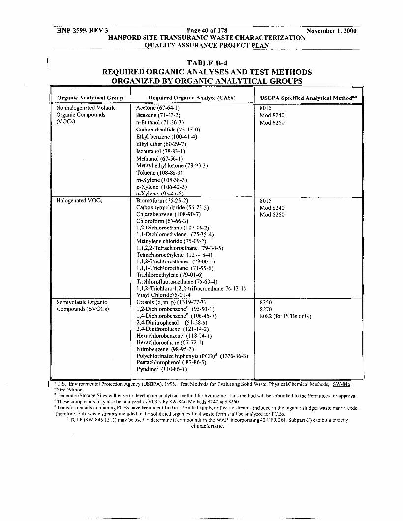
Required Organic Analyte (CAS#)
Acetone (67-64-1) Benzene (71-43-2) n-Butanol(71-36-3) Carbon disulfide (75-15-0) Ethyl benzene(100-41-4) Ethyl ether (60-29-7) lsohutanol(78-83-1) Methanol (67-56-1) Methyl ethyl ketone (78-93-3) Toluene (108-88-3) rn-Xylene (108-38-3) pXylene (106-42-3) o-Xylene (9547-6) Bromoform (75-25-2) Carbon tetrachloride (56-23-5) Chlorobenzene ( I 08-90-7) Chlomform (67-66-3) I ,2-Dichloroethane ( I 07-06-2) 1,l -Dichloroethylene (75-35-4) Methylene chloride (75-09-2) 1,1,2,2-Tetrachloroethane (79-34-5) Tetrachloroethylene (127-1 8-4) 1,1,2-Trichloroethane (79-00-5) I , I , I -Trichloroethane (71 -55-6) Trichloroethylene (79-01 -6) Trichlorofluoromethane (75-69-4) 1 , I ,2-Trichloro-1,2,2-trifluoroethane(76-13-1) Vinyl Chloride75-01-4 Cresols (o,m,p)(1319-77-3) 1,2-Dichlorohenzenec (95-50.1) 1,4-Dichlorohenzene' ( I 06-46-7) 2,4-Dinitrophenol (5 1-28-5) 2,4-Dinifrotoluene (121 -14-2) Hexachlorobenzene (1 18-74.1) Hexachloroethane (67-72- I ) Nitrobenzene (98-95-3) Polychlorinated biphenyls (PCB)d (1 336-36-3) Pentachlorophenol ( 87-86-5) PyidineC (110-86-1)
Nonhalogenated Volatile OTgantc Compounds (VOCS)
Halogenated VOCs
Semivolatile Organic Compounds (SVOCs)
1- Third Edition
HNF-2599, REV 3 Page 40 of 178 November 1,2000 HANFORD SITE TRANSURANIC WASTE CHARACTERIZATION
QUALITY ASSURANCE PROJECT PLAN
NlZED B\' OKG.4KIC ANI\I.\'TICAL CROUPS 1
- 1 cy (USEPA), 1996, "Tcsl Methds for Fvaluating Solid Waste. PhysicallChemical Methods." sw-846,
GeneratorIStorage Sites will have IO develop an analytical method for hydrazine. This method will be submitted to the Permittees for approval
Transformer oils containing PCBs have been identitied in a limited numher of waste streams included in the organic sludges waste matrix code
' TC'1.P (SW-846 131 I ) may be used todetermine ifcomporinds in the WAP (Incorporating40 C'FR261, SubpmC)exhibit a toxicity characteristic.
'These compounds may also be analyzed as VOCs by SW-846 Mcthods 8240 and 8260.
.Iherefore, only waste streams included in the solidified organics final w b t e hm shall be analyzed for PCBs.
USEPA Specified Analytical Method'"
8015 Mod 8240 Mod 8260
8015 Mod 8240 Mod 8260
8250 8270 8082 (for PCBs only)

HNF-2599, REV 3 Page 41 of 178 November 1,2000 HANFORD SITE TRANSURANIC WASTE CHARACTERIZATION
QUALITY ASSURANCE PROJECT PLAN
TABLE B-5 SUMMARY OF SAMPLE PREPARATION AND
ANALYTICAL METHODS FOR METALS
I
Parameters
Sample Preparation
Total Antimony
Total Arsenic
Total Barium
Total Beryllium
Total Cadmium
Total Chromium
Total Lead
Total Mercury
Total Nickel
Total Selenium
Total Silver
Total Thallium
Total Vanadium
Total Zinc
USEPA-Specified Analytical
3051, or equivalent, as appropriate for analytical method
6010,6020,7040,7041,7062
6010,6020,7060,7061,7062
6010,6020,7080,7081
6010,6020,7090,7091
6010,6020,7130,7131
6010,6020,7190,7191
6010,6020,7420,7421
7471
6010,6020,7520,7521
6010,7740,7741,7742
6010,6020,7760,7761
6010,6020,7840,7841
6010,7910,791 1
6010,6020,7950,7951
1 US. Environmental Protection Agency (USEPA), 1996. "Test Methods for Evaluating Solid Waste," Laboratory Manual PhyricaliChemical Methods, M, 3rd ed., U.S. Environmental Protection Agency, Office of Solid Waste and Emergency Response, Washington, D.C.
TCLP (SW-846 131 I) may bc used to determine if compounds in the WAP (incorporating 40 CFR 261, Subpart C) exhibit a toxicitv characteristic.

HNF-2599, REX 3 Page 42 of 178 November 1,2000 HANFORD SITE TRANSURANIC WASTE CHARACTERIZATION
QUALITY ASSURANCE PROJECT PLAN
TABLE € 4 4 SUMMARY OF PARAMETERS, CHARACTERIZATION METHODS. AND
I ~
Waste Matrix Code
I
ialids
,5000 Debris Waste
L4TIONAI.E FOR \ \ ~ \ t c \ la tr i i <ode <;roup,
t Solidified inorganics t Salt waste I Solidified organics
t Contaminated soilldebris
I Uncategorized metal (metal waste other than leadlcadmium)
, l~eadlcadmium waste , Inorganic nonmetal waste , Combustible waste , (;raphifr waste , Heterogeneous waste , Composite f i l ter waste
-
:H TRANSURA Characterization
Parameter - Physical Waste Form
Headspace gases . Gas "Dlatlle orgamc compounds (VOC)
Hazardous constituents: . TCLPl total metals . 'ICLPItotal v o c s * 'fC1,Pltatal semi-
Physical waste form VOCS
Headspace gases: . GasVOCs
C WASTE (STC Method -
100% radiography or vis, examination
lCQ% gas sampling and analysis or ~ta t i~ t i ea l sampling rb (see Table B
Statlstlcal samplmg~ (see Tables B-4 and E-5)
100% Radiography OT vis examination (statistical sample )" or vistial examination
100%gar sampling and analysis (see Table B-3)
Acceptable Knowledge
Rationale
Verify waste matux * Demonshate compliance with waste
acceptance citeria (e.g., no free liquids, no incompatible wasles, no compressed gases) Quantify concentration of flammable v o c s Determine potential flammability of TRU mixed waste headspace gases Quantify concentrations of VOC constituents in headspace ofcontainen
* Ensure that en~iroiimental performance standards are not exceeded Dctermine chaiactcristtc metals and OleanlCS
Iktermine total quantity of metals, VOCs. and semi-VOCs
Verify waste matrix Demonstrate compliance with waste acceptance (e.8.. no free liquids. no incompatible waste^. no compressed gases)
Quantify concentration of flammable v o c s Determine potential flammahility of TRU mixed waste headspace gases
* Quantify concentration of VOC constituents m headspace of containers
f Ensure that environmental performance standards are not exceeded
* Verify AK - Determine charactenstic metals and organics Dctermine total quantity of metals, VOCs and semi-VOCE
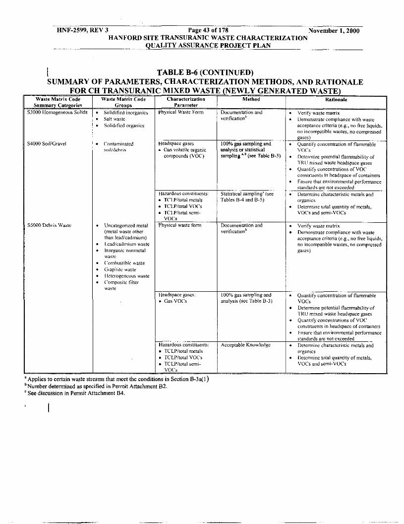
HNF-2599, REV 3 Page 43 of 178 November 1,2000 HANFORD SITE TRANSURANIC WASTE CHARACTERIZATION
QUALITY ASSURANCE PROJECT PLAN
I TABLE B-6 (CONTINUED) SUMMARY OF PARAMETERS, CHARACTERIZATION METHODS, AND RATIONALE
FOR Waste Matr ix Code
Summary Categories $3000 Homogeneous Solids
14000 SolliGravel
35000 Debris Waste
I TRANSURAN - Waste Matrix Code
Groups * Solidified inorganics * Salt waste b Solidified organics
- -
t Contaminated smlldebris
B Uncategorizcd metal (metal waste other than leadlcadmium)
B ILcadIcadmium waste B Inorganic nonmetal
n ('omhustible waste m Graphite waste . lleterogenc""s waste B Compusitc til ler
waste
waste
3 MIXED WA - Characterization
Parameter Physical Waste Form
Headspace gases . Gas volatile oiganir compounds (VOC)
Hazardous constituent TCLPltotal metals
* TCI Pltotal VOCs * TCLPltotal semi-
Physical waste form VOCs
Headspace gases: . GasVOCs
Hazardous c ~ n ~ t i l ~ e n l TCLPltotal metals
* TCLPItotal VOCs TCLPItotal semi- VOCS - _g
'Applies to certain waste streams that meet the conditions in Section B-3a(l bNumber determined ES specified in Permit Attachment B2. ' See discussion in Permit Attachment 84.
(NEWLY GENE1 ~
Method
Documentation and vcri f icat icd
100% gas sampling and analysis 01' statishcal samplingLb (see Table B-3)
Statistical sampling" (see 'Tables 8-4 and B-5)
Documentation and verification'
100% gas sampling and analysis (see Table B-3)
Acceptable Knowledge
Hslionnle
Verify waste matrix
acceptance criteria (e .g . , no free liquids, no incompatible wastes. no compressed gases)
* Quantiry concentration of flammable VOCS
* Oetel-mine potential flammability of ~Tl<II mired waste headspace gases - Quantify concentrations of VOC coiislituents in headspace of containers
* Enarirr that environmental performance standards are not exceeded Iletermine characteristic metals and organics I)ctcrmine total quantity of metals, VOCE and semi-VOCs
Verify waste matrix
acceptance criteria (c.g., no free liquids, n o incompatible wastes, no compressed
* Dcmonstratc compliance with waste
Demonstrate compliance with waste
gaSL5)
* Quantify concentrailon of flammable
Determine potential flammability of
. Quan1,fy ConCentratlOnS of VOC
VOCS
' IKU mixed waste headspace gases
ciinstitwnts m headspacc of containers * Ensure that environmental performance
standards arc not exceeded Determine characteristic metals and "iganlcs Detennine total quantity of metals, VOCs and semi-VOCs

HNF-2599, REV 3 Page 44 of 178 November 1,2000 HANFORD SITE TRANSURANIC WASTE CHARACTERIZATION
QUALITY ASSURANCE PROJECT PLAN
TABLE B-7 REQUIRED PROGRAM RECORDS MAINTAINED IN GENERATOWSTORAGE SITE
PROJECT FILES
I
Lifetime Records
Field sampling data forms Field and laboratory chain-of-custody forms Test facility and laboratory batch data reports Waste stream characterization package Sampling Plans Data reduction, validation, and reporting documentation AK documentation Data reconciliation report WSPF and characterization information summary
Nonpermanent Records Nonconformance documentation Variance documentation Assessment documentation Gas canister tags Methods performance documentation
Sampling equipment certifications
Training/qualification documentation
Calibration documentation Analytical raw data Procurement documentation QA procedures (all revisions)
Performance Demonstration Program (PDP) documentation
Calculations and related software documentation
QAPjPs (generator/storage sites) documentation (all revisions)
Technical implementing procedures (all revisions) Audioivideo recording (radiogaphy, visual, etc.)

HNF-2599, REV 3 Page 45 of 178 November 1,2000 HANFORD SITE TRANSURANIC WASTE CHARACTERIZATION
QUALITY ASSURANCE PROJECT PLAN
Figure B-1 Example Only WIPP WASTE STREAM PROFILE FORM (sheet 1 of 2)
I Waste Stream Profile Number 1 Generator Site Name 2 Technical Contact: 3 Generator Site USEPA TD: 2 Technical Contact phone number: 3 Date of audit report approval by NMED:4 Title, version number, and date of documents used for WAC Certification:
Did your facility generate this waste? U Yes 0 No If no, provide the name and USEPA ID of the
4
original generator: 5
Waste Stream Information (') WIPP ID: 6 Summary Category Group: 7 Waste Matrix Code Group: 8 Waste Stream Name: 9 Description from the WTWBIR: 10
Defense Waste: 0 Yes 0 No Check one: 0 CH 0 RH Number of SWBs 11 Number of Drums 11 Number of Canisters 11
12 List applicable USEPA Hazardous Waste Codes'" Applicable TRUCON Content Codes: 14
Acceotable Knowledee Information"' [For the following, enter supporting the documentation used (i.e., references and dates)] Required Promam Information
Batch Data Report numbers supporting this waste stream characterization: 13
Map of site: 15 Facility mission description: 15 Description of operations that generate waste: 15
Waste identificatiodcategorization schemes: 15 Types and quantities of waste generated: 15 Correlation of waste streams generated from the same building and process, as appropriate:-
Waste certification procedures: 15 Required Waste Stream Information
16 Waste stream volume and time period of generation: 16 Waste generating process description for each building: 16 Process flow diagrams: 16
Which Defense Activity generated the waste: (check one) 16
Area(s) and building(s) from which the waste stream was generated:
Material inputs or other information identifying chemicaliradionuclide content and physical waste form: 16
0 Weapons activities including defense inertial confinement fusion U Naval Reactors development 0 Verification and control technology n Defense Research and development 0 Defense nuclear waste and material by products management D Defense nuclear materials production 0 Defense nuclear waste and materials security and safeguards and security investigations

HNF-2599, REV 3 Page 46 of 178 November 1,2000 HANFORD SITE TRANSURANIC WASTE CHARACTERIZATION
QUALITY ASSURANCE PROJECT PLAN
Figure B-1 Example Only WIPP WASTE STREAM PROFILE FORM (sheet 2 of 2)
I Suuplemental Documentation
Process design documents 17 Standard operating procedures: 17 Safety Analysis Reports: 17 Waste packaging logs: 17 Test plansiresearch project reports: 17 Site data bases: 17 Information from site personnel: 17 Standard industry documents: 17
Material safety data sheets: 17
Laboratory notebooks: 17
Samoling and Analysis Information"' [For the following, when applicable, enter procedure titltfs), number($, and date(s)]
Previous analytical data: 17
Sampling and analysis data from comparableisurrogate Waste: 17
0 Radiography: 18 Visual examination: 18
0 Headspace Gas Analysis v o c s : 19 Flammable: 19 Other gases (specify): 19 0 Homogeneous SolidsiSoilsiGravel Samule Analysis Total metals: 20 PCBs: 20 vocs: 20 Nonhalogenated VOCs: 20 Semi-VOCs: 20 Other (specify): 20
Waste Stream Profile Form certification: I herebv certifv that I have reviewed the information in t h ~ s Waste Stream Profile Form, and it is complete and accurate to the best oimy kn&ledge. I understand that this information will be made available to regulatory agencies and that there are significant penalties for submitting false information, including the possibility of fines and imprisonment for lolowing violations.
Signature of Site Project Manager Printed Name and Title Date
NOTE: ( I ) Use back of sheet or continuation sheets, if required. (2 ) If radiography, visual examination, headspace gas analysis, andor homogeneous
soliddsoildgmvel sample analysis were used to determine USEPA Hazardous Waste Codes, attach signed characterization information summary documenting this determination.
I I

HNF-2599, REV 3 Page 47 of 178 November 1,2000 HANFORD SITE TRANSURANIC WASTE CHARACTERIZATION
QUALITY ASSURANCE PROJECT PLAN
I Figure B-2. Data Collectieu Design for Characterization of Newly Generated Waste
Perform hcadapscc gu sampling and n g r i r

HNF-2599, REV 3 Page 48 of 178 November 1,2000 HANFORD SITE TRANSIIRANIC WASTE CHARACTERIZATION
QUALITY ASSIJRANCE PROJECT PLAN
I Figure B-3. Data Caection Design for Charaeterbtion of RetrievaMy Stored Waste n
N O

HNF-2599, REV 3 Page 49 of 178 November 1,2000 HANFORD SITE TRANSURANIC WASTE CHARACTERIZATION
QUALITY ASSURANCE PROJECT PLAN
B1 WASTE CHARACTERIZATION SAMPLING METHODS
B1-1 Headspace-Gas Sampling
B1-la Method Requirements
Headspace gas sample results are used to determine the types and concentrations of VOCs in the void volume of waste containers. Headspace-gas sampling is performed in an appropriate radiation containment area on waste containers that are in compliance with the container equilibrium requirement (72 hours at 18” C or higher). All waste containers (or randomly selected containers from waste streams that meet the conditions for reduced headspace gas sampling listed in Section B-3a(l)) designated as Summary Category S5000 (debris waste) shall be sampled for headspace gas a minimum of 142 days after packaging. All waste containers or randomly selected containers from waste streams that meet the conditions for reduced headspace-gas sampling listed in Section B-3a( 1) designated as Summary Categories S3000 (homogenous solids) and S4000 (soil/gravel) shall be sampled a minimum of 225 days after
I packaging. The equilibrium time and drum age of all containers from which a headspace-gas sample is collected will be documented in headspace-gas sampling documents. All waste containers with unvented rigid containers greater than four liters, except for Waste Material Type 11.2 packaged in metal container, shall be subject to innermost layer of containment sampling or shall be vented prior to initiating drum age and equilibrium criteria. Headspace-gas samples will be analyzed for the analytes listed in Table B3-2 of Section B3. VOC constituents will be compared to those identified by AK for assignment of hazardous waste codes and reported to WIPP using the WWIS.
Samples are collected in SUMMATM or equivalent canisters using standard headspace-gas I sampling methods that meet the general guidelines established by the USEPA in the
Compendium Method TO-14, Redetermination of Volatile Organic Compounds (VOC) in Ambient Air using Summa Passivated Canister Sampling and Gas Chromatography Analysis
I (USEPA 1988).
B1-la(1) Manifold Headspace Gas Sampling
NOTE - This method I S not currently used at Hanford and is provided as a discussion of what will be required. This section will be revised to include the latest WIPP permit requirements and to address the specifc methods and equipment that will be used, once identified.
Samples are collected using a multiport manifold capable of collecting multiple simultaneous headspace samples for analysis and QC purposes. Headspace gas sampling is described in DO-080-009, “Obtain Headspace Gas Samples of TRU Waste Containers.” The sampling equipment is leak checked and cleaned prior to first use and as needed thereafter. The manifold and sample canisters will be evacuated to 0.0039 inches (in.) (0.10 millimeters [mm])
I mercury (Hg) or less prior to sample collection. Cleaned and evacuated sample canisters will be attached to the evacuated manifold before the manifold inlet valve is opened. The manifold inlet valve will be attached to a changeable filter connected to either a side port needle sampling head (for penetrating,a carbon-composite filter) or a punch sampling head (capable of punching through the metal’ l id ,a ta drum).

HNF-2599, REV 3 Page 50 of 178 November 1,2000 HANFORD SITE TRANSURANIC WASTE CHARACTERIZATION
QUALITY ASSURANCE PROJECT PLAN
The manifold is equipped with a purge assembly that allows QC samples to be collected through all sampling components that may affect compliance with the QAOs. Field blanks are samples of room air collected in the sampling area in the immediate vicinity of the waste container to be sampled. If using SUMMATM or equivalent canisters, field blanks may be collected directly into the canister, without the use of the manifold, if appropriate.
The manifold, the associated sampling heads, and the headspace-gas sample volume requirements have been designed to ensure that a representative sample is collected. The manifold internal volume has been calculated and documented in the field logbook dedicated to headspace-gas sample collection. Logkeeping is described in WMH-400, Section 8.1 .l, “Logkeeping Practices for WIPP Activities for Headspace Gas Sampling and Analysis.” The total volume of headspace gases collected during each sampling operation will be determined by adding the combined volume of the canisters attached to the manifold and the internal volume of the manifold. When an estimate of the available headspace gas volume in the drum can be made, less than 10 percent of that volume should be withdrawn.
The sampling manifold consists of a sample side and a standard side. The dotted line in Figure B1-1 indicates how the sample side shall be connected to the standard side for cleaning and collecting equipment blanks and field reference standards. The sample side of the sampling manifold consists of the following major components:
.
.
.
.
I .
1
A sampling head that forms a leak-tight connection with the headspace sampling manifold.
A flexible hose that allows movement of the sampling head from the purge assembly (standard side) to the waste container.
A pressure sensor pneumatically connected to the manifold and is able to measure absolute pressure in the range from 0.002 in. (0.05 mm) Hg to 39.3 in. (1,000 mm) Hg. Resolution for the manifold pressure sensors is +0.0004 in. (0.01 mm) Hg at 0.002 in. (0.05 mm) of Hg. The manifold pressure sensor has an operating range from approximately 59°F (15°C) to 104°F (40°C).
Available ports for attaching sample canisters. A sufficient number of ports are available to allow simultaneous collection of headspace-gas samples and duplicates for VOC analyses. Ports not occupied with sample canisters during cleaning or headspace-gas sampling activities require a plug or cap to prevent ambient air from entering the system. Ports have VCR fittings for connection to the sample canister(s) to prevent degradation of the fittings on the canisters and manifold.
Sample canisters that are leak-free, stainless steel pressure vessels, with a chromium-nickel oxide (Cr-Ni0)-passivated interior surface (such as SUMMATM), bellows valve, and a pressurehacuum gauge. Equivalent designs, such as Silco Steel canisters, may also be used. All sample canisters have VCR fittings for connection to sampling and analytical equipment. A pressdvacuum gauge is mounted on each manifold. The canister k/hdium-leak tested to
.

HNF-2599, REV 3 Page 51 of 178 November 1,2000 HANFORD SITE TRANSURANIC WASTE CHARACTERIZATION
QUALITY ASSURANCE PROJECT PLAN
1.5 x 10.’ standard cubic centimeters per second (ccis), has all stainless steel construction, and is capable of tolerating temperatures to 125°C. The gauge range is capable of operating in the leak-test range as well as the sample collection range.
. A dry vacuum pump with the ability to reduce the pressure in the manifold to 0.05 mm Hg. A vacuum pump that requires oil may be used, but precautions must be taken to prevent diffusion of oil vapors back to the manifold.
. A minimum distance, based upon the design of the manifold system, between the tip of the needle and the valve that isolates the pump from the manifold to minimize the dead volume in the manifold.
. An organic vapor analyzer (OVA) that is capable of detecting all analytes listed in Table B3-2 of Section B3. The OVA is capable of measuring total VOC concentrations below the lowest headspace gas PRQL. The OVA measurement shall be confirmed by the collection of equipment blanks at the frequency specified in Section B1-1 to check for manifold cleanliness.
The standard side must consist of the following major elements:
. A cylinder of compressed zero air, helium, argon, or nitrogen gas to clean the manifold between samples and to provide gas for the collection of equipment blanks. These high-purity gases are certified by the manufacturer to contain less than 1 ppm total VOCs. The gases are metered into the standard side of the manifold using devices that are corrosion proof and that do not allow for the introduction of manifold gas into the purge gas cylinders. Alternatively, a zero air generator may be used, provided a sample of the zero air is collected and demonstrated to contain less than 1 ppm total VOCs. Zero air from a generator shall be humidified.
. Cylinders of field-reference standard gases. Each cylinder of field-reference gas has a flow-regulating device. The field-reference standard gases are certified by the manufacturer to contain analytes from Table B3-2 of Section B3 at known concentrations.
. Humidifier filled with American Society for Testing and Materials (ASTM) Type I1 water, connected, and opened to the standard side of the manifold between the compressed gas cylinders and the purge assembly is used. In lieu of the humidifier, the compressed gas cylinders (e.g., zero air and field-reference standard gas) may contain water vapor in the concentration range of 1,000 to 10,000 parts per million by volume (PPmv)
A purge assembly that allows the sampling head (sample side) to be . connected to the standard side of the manifold. The ability to make this connection is required to transfer gases from the compressed gas cylinders to the canisters. This connection is also required for system cleaning.

HNF-2599, REV 3 Page 52 of 178 November 1,2000 HANFORD SITE TRANSURANIC WASTE CHARACTERIZATION
QUALITY ASSURANCE PROJECT PLAN
. A flow-indicating device or a pressure regulator that is connected to the purge assembly to monitor the flow rate of gases through the purge assembly. The flow rate or pressure through the purge assembly is monitored to ensure that excess flow exists during cleaning activities and during QC sample collection. Maintaining excess flow will prevent ambient air from contaminating the QC samples and allow samples of gas from the compressed gas cylinders to be collected near ambient pressure.
In addition to a manifold consisting of a sample side and a standard side, the area in which the manifold is operated shall contain sensors for measuring ambient pressure and ambient temperature, as follows:
. The ambient-pressure sensor has a sufficient measurement range for the ambient barometric pressures expected at the sampling location. It is kept in the sampling area during sampling operations. Its resolution is 0.039 in. (1 .O mm) Hg or less, and calibration performed is based on National Institute of Standards and Technology (NIST) or equivalent standards in accordance with WMH-400, Section 2.4.4, "TRU Control of Measuring, Testing and Data Collection Equipment" (see Table A-I),
. The temperature sensor has a sufficient measurement range for the ambient temperatures expected at the sampling location, 18" to 50" C. The temperature sensor calibration is traceable to NIST or equivalent standards in accordance with WMH-400, Section 2.4.4.
B1-la(2) Direct Canister Headspace Gas Sampling
This headspace-gas sampling protocol employs a canister-sampling system to collect headspace-gas samples for analysis and QC purposes without the use of the manifold described in Section B1-1 a(]). Rather than attaching sampling heads to a manifold, in this method the sampling heads are attached directly to an evacuated sample canister as shown in Figure B1-3a, 3b. Samples are collected in accordance with DO-080-009 (see Table A-1).
Canisters are evacuated to 0.0039 in. (0.10 mm) Hg or less prior to use and attached to a changeable filter connected to the appropriate sampling head. The sampling head is capable of punching through the metal lid of the containers, penetrating a carbon-composite filter, or penetrating an equivalent gas-tight seal to obtain the headspace samples. Field duplicates are collected at the same time, in the same manner, and using the same type of sampling apparatus as used for headspace-gas sample collection. Field blanks are samples of room air collected in the immediate vicinity of the waste-drum sampling area prior to removal or puncturing the container lid. Equipment blanks and field-reference standards are collected using a purge assembly equivalent to the standard side of the manifold described in Section Bl-la(1). These samples are collected from the needle tip through the same components (e.g., needle and filter) that the beadspace-gas samples pass through.
I
The sample canisters, associated sampling heads, and the headspace-sample volume requiments -e that a representative sample is collected. When an estimate of the available

HNF-2599, REV 3 Page 53 of 178 November 1,2000 HANFORD SITE TRANSURANIC WASTE CHARACTERIZATION
QUALITY ASSURANCE PROJECT PLAN
headspace-gas volume of the waste container can be made, less than 10 percent of that volume should be withdrawn. A determination of the sampling head internal volume has been made and documented. The total volume of headspace gases collected during each headspace gas sampling operation can be determined by adding the volume of the sample canister(s) attached to the sampling head to the internal volume of the sampling head. The internal volume of sampling heads is minimized.
Each sample canister used with the direct canister method has a pressurehacuum gauge capable of indicating leaks. Canister gauges are intended to be gross leak-detection devices not vacuum-certification devices. If a canister pressureivacuum gauge indicates an unexpected pressure change, determination of whether the change is a result of ambient temperature and pressure differences or a canister leak is made. This gauge is helium-leak tested to 1.5 x 10.’ standard cck, has stainless steel construction, and is capable of tolerating temperatures to 125°C.
The SUMMATM or equivalent sample canisters as specified in USEPA’s Compendium Method TO-14 (USEPA 1988) are used when sampling each drum. A sampling head is attached to the canister to collect the sample. These heads shall form a leak-tight connection with the canister and allow sampling through the drum-lid carbon-composite filter or through the drum lid itself. Figure B1-3 illustrates the direct canister-sampling equipment.
B1-la(3) Sampling Heads
A sample of the headspace gas directly under the lid is collected from within the container. Two methods, sampling through the carbon filter and sampling through the drum lid, have been developed for collecting a representative sample. Both sampling methods preserve the integrity of the drum to contain radionuclides (e.g., replace the damaged filter, seal or replace the punched container lid).
Bl-la(3)(i) Sampling Through the Carbon Filter
To sample the headspace gas through the carbon-composite filter, a side-port needle (e.g., a hollow needle sealed at the tip with a small opening on its side close to the tip) is pressed through the filter and into the headspace beneath the lid in accordance with DO-080-009. This permits the gas to be drawn into the manifold or directly into the canister. To ensure that the sample collected is representative, all of the general method requirements, sampling apparatus requirements, and QC requirements described in this section will be met in addition to the following requirements that are pertinent to headspace-gas sampling through the carbon filter:
. When present, the lid of the drum’s 90-mil poly liner shall contain a hole for venting to the drum or be vented using a filter. A representative sample cannot be collected until the poly liner has been vented to the drum. If headspace-gas samples are collected prior to venting the 90-mil poly liner, the sample is not acceptable. A sample may then be collected from beneath the lid of the rigid liner lid.
. For sample collection, the carbon-composite filter is sealed to prevent outside air from entering the drum and diluting and contaminating the sample.

HNF-2599, REV 3 Page 54 of 178 November 1,2000 HANFORD SITE TRANSIJRANIC WASTE CHARACTERIZATION
QUALITY ASSURANCE PROJECT PLAN
The sampling head for collecting headspace by penetrating the carbon-composite filter consists of a side-port needle, a filter to prevent particles from contaminating the gas sample, and an adapter to connect the side-port needle to the filter. To prevent cross contamination, the sampling head is cleaned or replaced after sample collection, after field-reference standard collection, and after field-blank collection. The following requirements also apply:
. The housing of the carbon-composite filter allows insertion of the sampling
The side-port needle is required for sampling to reduce the potential for plugging.
The purge assembly has been modified for compatibility with the side-port
needle through the filter element into the drum headspace.
.
. needle.
Bl-la(3)(ii) Sampling Through the Drum Lid
To sample the headspace gas through the lid, the lid shall be breached using an appropriate punch, as described in DO-080-009. The punch forms an airtight seal between the drum lid and the manifold or direct canister. Other sampling methods may be employed (e.g., self-tipping gas-tight screw) as long as the method ensures an airtight seal. To ensure that the sample collected is representative, all of the general method requirements, sampling
I apparatus requirements, and QC requirements specified in USEPA's Compendium Method TO-14 (USEPA 1988), as appropriate, are met in addition to the following requirements:
. The seal between the container lid and sampling head is designed to minimize intrusion of ambient air.
. All components of the punch sampling system that come into contact with sample gases shall be purged with humidified zero air, nitrogen, or helium prior to sample collection.
. Equipment blanks and field reference standards are collected through all the components of the punch that contact the headspace-gas sample.
Pressure shall he applied to the punch until the lid has been breached. . . Provisions shall be made to relieve potential container pressure increases during
punch operations; pressure increases may occur during sealing of the punch to the lid.
. If present, the lid of a drum 90-mil poly liner shall contain a hole for venting to the drum or vented through a filter. A representative sample cannot be collected until the poly liner has been vented to the drum. If headspace-gas samples are collected prior to venting the 90-mil poly liner, the sample is not used. The sampling may then be collected from beneath the rigid liner lid.
. During sampling, the carbon-composite filter, if present, shall be sealed to prevent outside air from entering the container.

HNF-2599, REV 3 Page 55 of 178 November 1,2000 HANFORD SITE TRANSURANIC WASTE CHARACTERIZATION
QUALITY ASSURANCE PROJECT PLAN
. While sampling through the drum lid using a manifold sampling, a flow-
I indicating device or pressure regulator to verify flow of gases shall be pneumatically connected to the drum punch sampling assembly and operated in the same manner as the flow-indicating device described above in Section Bl-la(l) .
. Equipment shall be used to adequately secure the punch sampling system to the lid.
B1-lb Quality Control
For manifold and direct canister sampling systems, field QC samples shall be collected on a per-sampling-batch basis, in accordance with DO-080-009. A sampling batch is a suite of samples collected consecutively using the same sampling equipment within a specific time period. A sampling batch can be up to 20 samples (excluding QC samples), all of which shall be collected within 14 days of the first sample in the batch. Holding temperatures and container requirements for gas sample containers are provided in Table B1-1. An on-line batch is the number of headspace-gas samples collected and analyzed within a 12-hour period using the same on-line integrated analysis system. The analytical batch requirements are specified by the analytical method being used in the on-line system. Table B1-2 provides a summary of field QC sample collection frequencies. Table B1-3 provides a summary of QC sample acceptance criteria.
The SQAO will monitor and document field QC sample results and fill out a nonconformance report if acceptance or frequency criteria are not met. The SPM will ensure appropriate corrective action is taken if acceptance criteria are not met.
B1-lb(1) Field Blanks
Field blanks are collected to evaluate background levels of program-required analytes. Field blanks are collected prior to collection of the first sample in the batch and at a frequency of one per sampling batch. The SPM will use the field blank data to assess impacts of ambient contamination, if any, on the sample results. Field blank results determined by GCMS and gas chromatography/flame ionization detection (GC/FID) is acceptable if the concentration of each VOC analyte is less than or equal to three times the method detection limit (MDL) listed in Table B3-2 in Section B3. An NCR will be initiated and resolved if the final reported QC sample results do not meet the acceptance criteria.
B1-lb(2) Equipment Blanks
Equipment blanks are collected to assess cleanliness prior to first use and after cleaning of all sampling equipment. After the initial cleanliness check, equipment blanks collected through a manifold shall be collected at a frequency of one per sampling batch for VOC analysis or one per day, whichever is more frequent. When the direct canister method is used, field blanks are used in lieu of equipment blanks. The SPM uses the equipment blank data to assess impacts of potentially contaminated sampling equipment on the sample results. Equipment

HNF-2599, REV 3 Page 56 of 178 November 1,2000 HANFORD SITE TRANSURANIC WASTE CHARACTERIZATION
QUALITY ASSURANCE PROJECT PLAN
blank results determined by GCMS or GCRID shall be acceptable if the concentration of each VOC analyte is less than or equal to three times the MDL listed in Table B3-2 in Section B3.
B1-lb(3) Field Reference Standards
Field reference standards shall be used to assess the accuracy with which the sampling equipment collects VOC samples into SUMMATM or equivalent canisters prior to first use of the sampling equipment. Field reference standards shall contain a minimum of six of the analytes listed in Table B3-2 in Section B3 at concentrations within a range of 10 to 100 ppmv and greater than the MDL for each compound. Field reference standards shall have a known valid relationship to a nationally recognized standard (e.g., NIST), if available. If NIST traceable standards are not available and commercial gases are used, a certificate of analysis from the manufacturer documenting traceability is required. Commercial stock gases shall not be used beyond their manufacturer-specified shelf life. After the initial accuracy check, field reference standards collected through a manifold shall be collected at a frequency of one per sampling batch and submitted as blind samples to the analytical laboratory (reference standard concentration unknown to the analyst). For the direct canister method, field reference standard collection may be discontinued if the field reference standard results demonstrate the QAO for accuracy specified in Section B3-2. Field reference standard results shall be acceptable if the accuracy for each tested compound has a recovery of 70 to 130 percent.
B1-1 b(4) Field Duplicates
Field duplicate samples are collected sequentially or simultaneously and in accordance with Table B1-1 to assess the precision with which the sampling procedure can collect samples into SUMMATM or equivalent canisters. Field duplicate results shall be acceptable if the relative percent difference (RPD) is less than or equal to 25 percent for each tested compound found in concentrations greater than the PRQL in both duplicates.
B1-lc Equipment Testing, Inspection and Maintenance
All sampling equipment components that come into contact with headspace sample gases shall be constructed of relatively inert materials such as stainless steel or Teflon.
I To minimize the potential for cross contamination of samples, the headspace gas sampling manifold and sample canisters are cleaned and leak-checked prior to each headspace- gas sampling event. Procedures used for cleaning and preparing the manifold and sample
1988) Cleaning requirements are presented below. Equipment cleaning procedures are provided in LO-080-407, “Clean SUMMA Canisters” (see Table A-1).
B1-lc(1) Headspace-Gas Sample Canister Cleaning
1 canisters are equivalent to those provided in USEPA’s Compendium Method TO-14 (USEPA
SUMMATM or equivalent canisters used in these methods are subjected to rigorous cleaning and certification procedures prior to use in the collection of any samples. Guidance for
Specific detailed instructions are provided in LO-080-407. I the development of this procedure has been derived from Method TO-14 (USEPA 1988).

HNF-2599, REV 3 Page 57 of 178 November 1,2000 HANFORD SITE TRANSURANIC WASTE CHARACTERIZATION
QUALITY ASSURANCE PROJECT PLAN
Canisters are cleaned and certified on an equipment cleaning batch basis. An equipment cleaning batch is any number of canisters cleaned together at one time using the same cleaning method. A cleaning system, capable of processing multiple canisters at a time, composed of an oven (optional) and a vacuum manifold that uses a dry vacuum pump or a cryogenic trap backed by an oil sealed pump shall be used to clean SUMMATM or equivalent canisters. Prior to
I cleaning, a positive or negative pressure leak test is performed on all canisters. The duration of the leak test must be greater than or equal to the time it takes to collect a sample, but not greater than 24 hours. For a leak test, a canister passes if the pressure does not change at a rate of more than + 2 psig per 24 hours. Any canister that fails shall be checked for leaks, repaired, and reprocessed. One canister per equipment cleaning batch is filled with humid zero air or humid high purity nitrogen and analyzed for VOCs. The equipment cleaning hatch of canisters is clean if there are no VOCs above three times the MDLs listed in Table B3-2 of Section B3. After the canisters have been certified for leak-tightness and found to be free of background contamination, they are evacuated to 0.0039 in. (0.10 mm) Hg or less for storage prior to shipment. The laboratory responsible for canister cleaning and certification will maintain canister certification documentation and initiate the canister tags as described in Section B3.
B1-lc(2) Sampling Equipment Initial Cleaning and Leak Check
The surfaces of all headspace-gas sampling equipment components that will come into contact with headspace gas are thoroughly inspected and cleaned prior to assembly. Manifolds and associated sampling heads are purged with humidified zero air, nitrogen, or helium, and leak checked after assembly. This cleaning is repeated if the manifold or associated sampling heads are contaminated to the extent that the routine system cleaning is inadequate. Equipment cleaning and leak check procedures are provided in DO-080-009 and LO-080-407.
B1-lc(3) Sampling Equipment Routine Cleaning and Leak Check
Manifolds and associated sampling heads which are reused are cleaned and checked for leaks in accordance with the cleaning and leak check procedures described in USEPA's Compendium Method TO-14 (USEPA 1988) and DO-080-009. This is conducted after headspace gas and field duplicate collection, after field blank collection, after field blanks are collected through the manifold, and after the additional cleaning required for field reference standard collection has been completed. The protocol for routine manifold cleaning and leak check requires that sample canisters be attached to the canister ports or that the ports be capped or closed by valves, and requires that the sampling head be attached to the purge assembly.
VOCs are removed from the internal surfaces of the headspace sampling manifold to levels that are less than or equal to three times the MDLs of the analytes listed in Table B3-2 of Section B3, as determined by analysis of an equipment blank or through use of an OVA. When not in use, the manifold shall be demonstrated clean before storage with a positive pressure of high purity gas (e.g., zero air, nitrogen, or helium) in both the standard and sample sides.
Sampling shall be suspended and corrective actions shall be taken when the analysis of an equipment blank indicates that the VOC limits have been exceeded or if a leak test fails. The SPM will ensure that corrective action has been taken prior to resumption of sampling.

HNF-2599, REV 3 Page 58 of 178 November 1,2000 HANFORD SITE TRANSURANIC WASTE CHARACTERIZATION
QUALITY ASSURANCE PROJECT PLAN
Equipment cleaning and leak check procedures are provided in DO-080-009 and LO-080-407.
B1-lc(4) Manifold Cleaning After Field Reference Standard Collection
Manifold sampling is not currently in use at Hanford. NOTE ~
The sampling system will be specially cleaned after a field reference standard has been collected because the field reference standard gases contaminate the standard side of the headspace sampling manifold when they are regulated through the purge assembly. This cleaning requires the installation of a gas-tight connector in place of the sampling head between the flexible hose and the purge assembly. After this protocol has been completed and prior to collecting another sample, the routine system cleaning and leak check (see previous section) is also performed.
B1-lc(5) Sampling Head Cleaning
To prevent cross contamination, the needle, adapters, and filter of the sampling heads are cleaned in accordance with the cleaning procedures described in USEPA’s Compendium Method
I TO-I4 (USEPA 1988) and LO-080-407. After sample collection, a sampling head will be disposed of or cleaned prior to reuse. As a further QC measure, the needle and filter, after cleaning, should be purged with zero air, nitrogen, or helium and capped for storage to prevent sample contamination by VOCs potentially present in ambient air. Equipment cleaning procedures are provided in LO-080-407.
B1-ld Equipment Calibration and Frequency
NOTE ~ Manifold sampling is not currently in use at Hanford.
The manifold pressure sensor shall be certified prior to initial use and then annually, using NIST traceable, or equivalent, standards. The ambient air temperature sensor, if present, shall be certified prior to initial use and then annually to NIST traceable, or equivalent, temperature standards. Calibration is performed in accordance with WMH-400, Section 2.4.4.
I
The OVA shall be calibrated once per day, prior to first use, or as necessary according to the manufacturer’s specifications. Calibration gases shall be certified to contain known analytes from Table B3-2 of Section B3 at known concentrations. The balance of the OVA calibration gas shall be consistent with the manifold purge gas when the OVA is used (e.g., zero air, nitrogen, or helium). OVA calibrations are addressed in DO-080-009.
B1-2 Sampling of Homogenous Solids and SoiVGravel
NOTE - The TRU Project has not fully implemented characterization of S3000 and S4000 wastes. This section is provided as a discussion of what will be required. This section will be revised to include the latest WIPPpermit requirements and address the speciJc methods and equipment that will be
I I used once identi$ed.
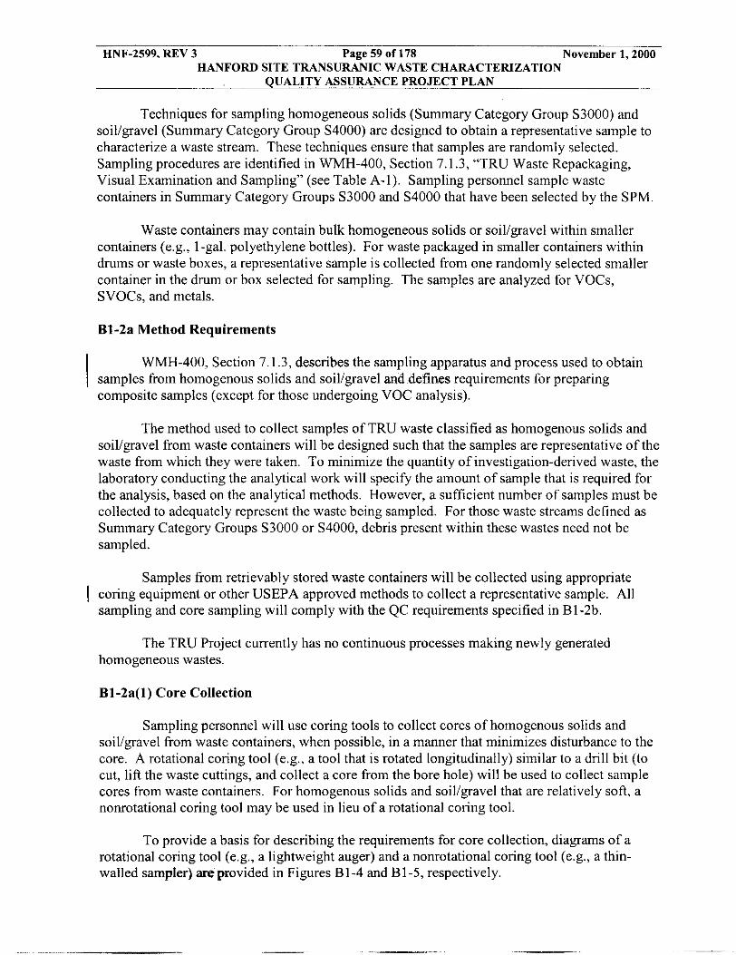
HNF-2599, REV 3 Page 59 of 178 November 1,2000 HANFORD SITE TRANSURANIC WASTE CHARACTERIZATION
QUALITY ASSURANCE PROJECT PLAN
Techniques for sampling homogeneous solids (Summary Category Group S3000) and soil/gavel (Summary Category Group S4000) are designed to obtain a representative sample to characterize a waste stream. These techniques ensure that samples are randomly selected. Sampling procedures are identified in WMH-400, Section 7.1.3, “TRU Waste Repackaging, Visual Examination and Sampling” (see Table A-1). Sampling personnel sample waste containers in Summary Category Groups S3000 and S4000 that have been selected by the SPM.
Waste containers may contain bulk homogeneous solids or soil/gravel within smaller containers (e.g., 1-gal. polyethylene bottles). For waste packaged in smaller containers within drums or waste boxes, a representative sample is collected from one randomly selected smaller container in the drum or box selected for sampling. The samples are analyzed for VOCs, SVOCs, and metals.
B1-2a Method Requirements
WMH-400, Section 7.1.3, describes the sampling apparatus and process used to obtain samples from homogenous solids and soiligavel and defines requirements for preparing composite samples (except for those undergoing VOC analysis).
The method used to collect samples of TRU waste classified as homogenous solids and soil/gravel from waste containers will be designed such that the samples are representative of the waste from which they were taken. To minimize the quantity of investigation-derived waste, the laboratory conducting the analytical work will specify the amount of sample that is required for the analysis, based on the analytical methods. However, a sufficient number of samples must be collected to adequately represent the waste being sampled. For those waste streams defined as Summary Category Groups S3000 or S4000, debris present within these wastes need not be sampled.
Samples from retrievably stored waste containers will be collected using appropriate I coring equipment or other USEPA approved methods to collect a representative sample. All
sampling and core sampling will comply with the QC requirements specified in B1-2b.
The TRU Project currently has no continuous processes making newly generated homogeneous wastes.
B1-2a(l) Core Collection
Sampling personnel will use coring tools to collect cores of homogenous solids and soil/gravel from waste containers, when possible, in a manner that minimizes disturbance to the core. A rotational coring tool (e.g., a tool that is rotated longitudinally) similar to a drill bit (to cut, lift the waste cuttings, and collect a core from the bore hole) will be used to collect sample cores from waste containers. For homogenous solids and soil/gravel that are relatively soft, a nonrotational coring tool may be used in lieu of a rotational coring tool.
To provide a basis for describing the requirements for core collection, diagrams of a rotational coring tool (e.g., a lightweight auger) and a nonrotational coring tool (e.g., a thin- walled sampler) areprovided in Figures B1-4 and B1-5, respectively.

HNF-2599, REV 3 Page 60 of 178 November 1 . 2 0 0 0 HANFORD SITE TRANSURANIC WASTE CHARACTERIZATION
QUALITY ASSURANCE PROJECT PLAN
The following requirements apply to the use of coring tools:
Each coring tool shall contain a removable tube (liner) that is constructed of fairly rigid material unlikely to affect the composition or concentrations of target analytes in the sample core. Materials that are acceptable for use for coring device sleeves are polycarbonate, TeflonTM, or glass for most samples, and stainless steel or brass if samples are not to be analyzed for metals. The TRU Project is not currently performing solid waste sampling. Prior to characterization of these waste streams, the TRU Project will revise this document to address the selection of liners to show that analytes of concern are not present in liner material. This discussion will document that the materials are unlikely to affect sample results through the collection and analysis of an equipment blank prior to first use as specified in the “Equipment Blanks” section. Before use, the liner will be cleaned in accordance the requirements in Section B1-2b. The liner will fit flush with the inner wall of the coring tool and shall he of sufficient length to hold a core that is representative of the waste along the entire depth of the waste. The depth of the waste is calculated as the distance from the top of the sludge to the bottom of the drum (based on the thickness of the liner and the rim at the bottom of the drum). The liner material will have sufficient transparency to allow VE of the core after sampling. If subsampling is not conducted immediately after core collection and liner extrusion, end caps constructed of material unlikely to affect the composition or concentrations of target analytes in the core (e.g., TeflonTM) shall he placed over the ends of the liner. End caps shall fit tightly to the ends of the liner. This document will also specify the materials used to make the end caps as well as the core liners.
A spring retainer, similar to that illustrated in Figures B1-4 and B1-5, will be used with each coring tool when the physical properties of the waste are such that the waste may fall out of the coring tool’s liner during sampling activities. The spring retainer will he constructed of relatively inert material (e.g., stainless steel or TeflonTM) and its inner diameter will not he less than the inner diameter of the liner. Before use, spring retainers shall he cleaned in accordance with the requirements in Section B1-2h.
Coring tools may have an air-lock mechanism that opens to allow air inside the liners to escape as the tool is pressed into the waste (e.g., ball check valve). If used, this air-lock mechanism will also close when the core is removed from the waste container.
After disassembling the coring tool, a device (extruder) to forcefully extrude the liner from the coring tool, will be used if the liner does not slide freely. All surfaces of the extruder that may come into contact with the core will be cleaned in accordance with the requirements in Section B1-2b prior to use.
Coring tools shall be of sufficient length to hold the liner and shall be constructed to allow placement of the liner leading edge as close as possible to the coring took leading edge.
I
e

HNF-2599, REV 3 Page 61 of 178 November 1,2000 HANFORD SITE TRANSURANIC WASTE CHARACTERIZATION
QUALITY ASSURANCE PROJECT PLAN
All surfaces of the coring tool that have the potential to contact the sample core or sample media shall be cleaned in accordance with the requirements in Section B1-2b prior to use.
I 0 The leading edge of the coring tools may be sharpened and tapered to a diameter equivalent to, or slightly smaller than, the inner diameter of the liner to reduce the drag of the homogenous solids and soiligravel against the internal surfaces of the liner, thereby enhancing sample recovery.
Rotational coring tools will have a mechanism to minimize the rotation of the liner inside the coring tool during coring activities, thereby minimizing physical disturbance to the core.
Rotational coring will be conducted in a manner that minimizes transfer of frictional heat to the core, thereby minimizing potential loss of VOCs.
Nonrotational coring tools will be designed such that the tool kerf width is minimized. Kerf width is defined as one-half of the difference between the outer diameter of the tool and the inner diameter of the tool inlet.
B1-2a(2) Sample Collection
Sampling of cores shall be conducted in accordance with the following requirements:
0
I 0
I I I
Sampling will be conducted as soon as possible after core collection. If a substantial delay (more than 60 minutes) is expected between core collection and sampling, the core shall remain in the liner and the liner shall be capped at each end. If the liner containing the core is not extruded from the coring tool and capped, the liner shall be left in the coring tool, and the coring tool shall be capped at each end.
Samples of homogenous solids and soiligravel for VOC analyses will be collected prior to extruding the core from the liner. These samples may be collected by collecting a single sample from the representative subsection of the core, or three sub- samples may be collected from the vertical core to form a single 15-gram composite sample. Smaller sample sizes may be used if method PRQL requirements are met for all analytes. The sampling locations will be randomly selected. If a single sample is used, the representative subsection is chosen by randomly selecting a locatian along the portion of the core (e.g., core length). If the three subsample method is used, the sampling locations shall be randomly selected within three equal-length subsections of the core along the long axis of the liner, and access to the waste shall be gained by making a perpendicular cut through the liner and the core. Sampling procedures will be prepared to select and record the selection of random sampling locations. A sampling device such as the metal coring cylinder described in USEPA’s SW-846 Manual (1996), or equivalent, will be immediately used to collect the sample once the core has been exposed to air. Immediately after sample collection, the sample shall be placed in an airtight sample container for VOA analysis, the top rim of the
visually inspected and wiped clean of any waste residue, and the cap

HNF-2599, REV 3 Page 62 of 178 November 1,2000 HANFORD SITE TRANSURANIC WASTE CHARACTERIZATION
QUALITY ASSURANCE PROJECT PLAN
secured. Sample handling requirements are outlined in Table B 1-4. Additional guidance for this type of sampling can be found in SW-846 (USEPA 1996). I
Samples of the homogenous solids and soiligravel for SVOC, PCB, and metals will be collected for analysis. These samples may he collected from the same suhsample locations and in the same manner as the sample collected for VOC analysis, or they may he collected by splitting or compositing the representative subsection of the core. The representative subsection is chosen by randomly selecting a location along the portion of the core (e.g., core length). Sampling procedures will he prepared to select and record the selection of random sampling locations. Guidance for splitting and cornpositing solid materials can he found in SW-846 (USEPA 1996). All surfaces of the sampling tools that have the potential to come into contact with the sample will be constructed of materials unlikely to affect the composition or concentrations of target analytes in the waste (e.g., TeflonTM). In addition, all surfaces that have the potential to come into contact with core sample media will either he disposed or decontaminated according to the procedures found in Section B1-2h. Sample sizes and handling requirements are outlined in Table B1-4.
Newly generated waste samples may he collected using methods other than coring, as discussed in Section B1-2a. Newly generated waste subsamples will be collected as soon as possible after sampling, but the spatial and temporal homogeneity of the waste stream dictate whether a representative grab sample or composite sample shall he collected.
B1-2b Quality Control
QC requirements for sampling homogenous solids and soiligravel include collecting co-located samples from cores or other sample types to determine precision; equipment blanks to verify cleanliness of the sampling and coring tools and sampling equipment; and analysis of reagent blanks to ensure reagents, such as deionized or high pressure liquid chromatography (HPLC) water, are of sufficient quality. WMH-400, Section 7.1.3, includes steps for demonstrating compliance with QAPjP QC requirements. Coring and sampling of homogenous solids and soil/gravel shall meet the following QC requirements.
B1-2b(l) Co-located Samples
In accordance with the requirement to collect field duplicates required by the USEPA I methods found in SW-846 (USEPA 1996), sampling personnel will collect QC samples to
determine the combined precision of the coring and sampling procedures. The co-located core methodology is a duplicate sample collection methodology intended to collect samples from a second core placed at approximately the same location within the drum when samples are collected by coring. Newly generated waste may not be amenable to coring in some instances. In this case, a co-located sample may he collected from a sample (e.g., a scoop) collected from approximately the same location in the waste stream. A sample from each co-located core or newly generated waste sample collected by other means will he collected side by side as close as feasible to one another, handled in the same manner, visually inspected through the transparent liner (if cored), and sampled in the same manner at the same randomly selected sample hxath(s~ W t k VE detects inconsistencies such as color, texture. wwaste type in, the waste at

HNF-2599, REV 3 Page 63 of 178 November 1,2000 HANFORD SITE TRANSURANlC WASTE CHARACTERlZATlON
QUALITY ASSURANCE PROJECT PLAN
the sample location, another sampling location may be randomly selected, or the samples may be invalidated and co-located samples or cores may again be collected. Co-located samples, from either core or other sample type, will be collected at a frequency of one per sampling batch (or once per week, whichever is more frequent, [see Section B3-31). A sampling batch is a suite of homogenous solids and soil/gravel samples collected consecutively using the same sampling equipment within a specific time period. A sampling batch can be up to 20 samples (excluding field QC samples), all of which shall be collected within 14 days of the first sample in the batch.
B1-2b(2) Equipment Blanks
The TRU Project intends to use certified, clean, disposable sampling equipment when I convenient. Certified sampling equipment and containers cleaned in accordance with USEPA
protocol and certified in accordance with the manufacturer are purchased. Otherwise, sampling personnel will clean sampling equipment and sample containers in accordance with the
I Spec$cation nnd Guidance for Obtaining Contaminant-Free Sample Containers (USEPA 1992).
Sampling personnel will clean, identify, and seal in protective wrapping sampling equipment in compliance with the WIPP-WAF’ and USEPA SW-846. Equipment blanks are collected from fully assembled sampling and coring tools (e.g., at least those portions of the sampling equipment that contact the sample) prior to first use after cleaning at a frequency of one per equipment cleaning batch. An equipment cleaning batch is the number of sampling equipment items cleaned together at one time using the same cleaning method. The equipment blank will be collected from the fully assembled sampling or coring tool, in the area where the sampling or coring tools are cleaned, prior to covering with protective wrapping and storage. The equipment blank will be collected by pouring clean water (e.g., deionized water, HPLC water) down the inside of the assembled sampling or coring tool. The water shall be collected in a clean sample container placed at the leading edge of the sampling or coring tool and analyzed for the analytes listed in Tables B3-4, B3-6, and B3-8.
Equipment blanks for coring tools will be collected from liners that are cleaned separately from the coring tools. These equipment blanks will be collected at a frequency of one per equipment cleaning batch. Equipment blanks will be collected by randomly selecting a liner from the equipment cleaning batch, pouring clean water (e.g., deionized water or HPLC water) across its internal surface, collecting the water in a clean sample container, and analyzing the water for the analytes listed in Tables B3-4, B3-6, and the program required detection limits (PRDLs) in Table B3-8.
Sampling equipment (e.g., bowls, spoons, chisel, VOC subsampler) will also be cleaned. Equipment blanks will be collected for the sampling equipment at a frequency of one per equipment cleaning batch. After the sampling equipment has been cleaned, one item from the equipment cleaning batch is randomly selected, water (e.g., deionized water, HPLC water) is passed over its surface, collected in a clean container, and analyzed for the analytes listed in Tables B3-4, B3-6, and B3-8.
The results of the equipment blanks will be considered acceptable if the results indicate no analyte present at a concentration greater than three times the MDLs listed in Tables B3-4 and B3-6 and in the PRDLs in B3-8. If analytes are detected at concentrations greater than three times the MDLs (or PRDLs for metals), the associated equipment cleaning batch will be
- I-

HNF-2599, REV 3 Page 64 of 178 November 1,2000 HANFORD SITE TRANSURANIC WASTE CHARACTERIZATION
QUALITY ASSURANCE PROJECT PLAN
cleaned again and another equipment blank collected. Equipment from an equipment cleaning batch may not be used until analytical results have been received verifying an adequately low level of contamination in the blank.
The above equipment blanks may be performed on a purchased batch basis for sampling equi.pment purchased sterile and sealed i performed for equipment purchased in s certifying cleanliness.
tective packaging. Equipment blanks nee protective packaging accompanied by a c
The results of equipment blanks will be traceable to the items in the equipment cleaning batch that the equipment blank represents. All sampling items will be identified, and the associated equipment cleaning batch will be documented. The method of documenting the connection between equipment and equipment cleaning batches will be determined by sampling personnel and discussed in the revision to this section in the future. Equipment blank results for the coring tools, liners, and sampling equipment will be reviewed prior to use. A sufficient quantity of these items should be maintained in storage to prevent disruption of sampling operations.
B1-2b(3) Coring Tool and Sampling Equipment Cleaning
Coring tools and sampling equipment will be cleaned in accordance with the following requirements:
e All surfaces of coring tools and sampling equipment that will come into contact with the samples will be clean prior to use. All sampling equipment will be cleaned in the same manner. Immediately following cleaning, coring tools and sampling equipment shall be assembled and sealed inside clean protective wrapping.
I
e Each reusable sampling or coring tool will have a unique identification number. Each number will be referenced to the waste container on which it was used. This information will be recorded in the field records. One sampling or coring tool from each equipment cleaning batch will be tested for cleanliness in accordance with the requirements specified above. The identification number of the sampling or coring tool from which the equipment blank was collected will be recorded in the field records. The results of the equipment blank analysis for the equipment cleaning batch in which each sampling or coring tool was cleaned will be submitted to the sampling facility with the identification numbers of all sampling or coring tools in the equipment cleaning batch. If analytes are detected at concentrations greater than three times the MDLs (or PRDLs for metals), the associated equipment cleaning batch of sampling equipment will be cleaned again and another equipment blank collected. Equipment from an equipment cleaning batch may not be used until analytical results have been received verifying an adequately low level of contamination in the equipment blank.
Sample containers will be cleaned in accordance with SW-846 (USEPA 1996) I e

HNF-2599, REV 3 Page 65 of 178 November 1,2000 HANFORD SITE TRANSURANIC WASTE CHARACTERIZATION
QUALITY ASSURANCE PROJECT PLAN
B1-2c Equipment Testing, Inspection and Maintenance
Prior to initiation of sampling or coring activities, sampling and coring tools will be tested in accordance with manufacturer's specifications to ensure operation within the manufacturer's tolerance limits. Other specifications specific to the sampling operations (e.g., operation of containment structure and safety systems) will also be tested and verified as operating properly prior to initiating coring activities. Coring tools will be assembled, including liners, and tested. Air-lock mechanisms and rotation mechanisms will be inspected for free movement of critical parts. Sampling and coring tools found to be malfunctioning will be repaired or replaced prior to use.
Coring tools and sample collection equipment will be maintained in accordance with manufacturer's specifications. Clean sampling and coring tools and sampling equipment will be sealed inside clean protective wrapping and maintained in a clean storage area prior to use. Sampling equipment will be properly maintained to avoid contamination. A sufficient supply of spare parts will be maintained to prevent delays in sampling activities due to equipment down time. Sampling personnel provide testing, inspection, and maintenance records to the project records custodian, as described in WMH-400, Section 1.5.1.
Inspection of sampling equipment and work areas will include the following:
0 Sample collection equipment in the immediate area of sample collection will be inspected daily for cleanliness. Visible contamination on any equipment (e.g., waste on floor of sampling area, hydraulic fluid from hoses) that has the potential to contaminate a waste core or waste sample will be thoroughly cleaned upon its discovery.
The waste coring and sampling work areas will be maintained in clean condition to minimize the potential for cross contamination between waste (including cores) and samples.
Expendable equipment (e.g., plastic sheeting, plastic gloves) will be visually inspected for cleanliness prior to use and properly discarded.
0
0
0 Prior to removal of the protective wrapping from a coring tool designated for use, the condition of the protective wrapping will be visually assessed. Coring tools with tom protective wrapping will be returned for cleaning. Coring tools visibly contaminated after the protective wrapping has been removed will not be used and shall be returned for cleaning or properly discarded.
Sampling equipment will be visually inspected prior to use. All sampling equipment that ultimately comes into contact with waste samples will be stored in protective wrapping until use. Prior to removal of the protective wrapping from sampling equipment, the condition of the protective wrapping will be visually assessed. Sampling equipment with tom protective wrapping will be discarded or returned for cleaning. Sampling equipment visibly contaminated after the protective wrapping has been removed will not be used and will be returned for cleaning or properly discarded.
0

HNF-2599, REV 3 Page 66 of 178 November 1,2000 HANFORD SITE TRANSURANIC WASTE CHARACTERIZATION
QUALITY ASSURANCE PROJECT PLAN
0 Cleaned sampling and coring equipment will be physically segregated from all equipment that has been used for a sampling event and has not been decontaminated.
B1-2d Equipment Calibration and Frequency
The scale used for weighing sub-samples will be calibrated as appropriate for the type of scale to maintain its operation within manufacturer’s specification, and after repairs and routine maintenance. Weights used for calibration will be traceable to a nationally recognized standard. Calibration records will be maintained in the field records.
B1-3 Radiography
The TRU Project nondestructive examination (NDE) system employs two different types of imaging technologies to examine box and waste container contents: real-time radiography (RTR) or linear diode array (LDA). These systems are used individually or together, depending on the information needed and the waste configuration. Throughout this section, the term radiography refers to either or both of these systems.
Using radiography, NDE personnel verify the matrix parameter category and estimate the weights of the waste material parameters listed in Table B3-1. To verify radiography results, personnel perform VE on a portion of the waste containers. This section describes the radiography and VE processes.
B1-3a Methods Requirements
Radiography has been developed to aid in the examination and identification of 1 containerized waste. There is no equivalent or associated method found in USEPA sampling and
analysis guidance documents.
The procedures used to achieve the radiography objectives are described in WWI-OP-0908 “TRU Waste Certification ~ Operation of the Drum Nondestructive Examination System” (see Table A-1). Trained radiography operators record data on procedure data sheets and audiohideotape or laser disk. An NCR will be initiated to resolve the inconsistency if radiography indicates that the waste does not match the waste stream description. A list of prohibited waste items and a standard weight lookup table is provided in WRP-OP-0908.
The NDE systems consist of an enclosure for radiation protection, an X-ray-producing device, waste container handling system, audiohideo recording system, and an operator control and data acquisition system. The RTR imaging chain uses an image intensifier to convert the X-rays to visible light, which is viewed by a television camera and displayed on a television monitor. The LDA uses a solid state scintillator to convert the X-rays to light photons, which are converted to digital signals and displayed on a high-resolution computer monitor. The X-ray producing device has controls that allow the operator to vary the voltage, thereby controlling image quality. It is possible to vary the voltage between 150 and 450 kilovolts (kV), to provide anophnm degree of penetration through the waste.

HNF-2599, REV 3 Page 67 of 178 November 1,2000 HANFORD SITE TRANSURANIC WASTE CHARACTERIZATION
QUALITY ASSURANCE PROJECT PLAN
To perform radiography, the waste container is scanned while the operator views the television screen. An audiohideotape (for RTR) or laser disk (for LDA) is made of the waste container scan and is maintained as a nonpermanent record. A radiography data form is also used to document and estimate waste material parameter weights of the waste. The estimated
I waste material parameter and weights are determined using a standard weight lookup table.
B1-3b Quality Control
NDE personnel ensure radiography quality through operator training and experience, and qualitative and semi-quantitative evaluations of visual displays. Additionally, TRU Project personnel verify the radiography results through VE of a statistically determined portion of waste containers. Operator training and experience are the most important considerations for ensuring quality controls in regard to the operation of the radiography system and for interpretation and disposition of radiography results.
Only trained personnel are allowed to operate radiography equipment to ensure quality in regard to radiography system operation and for interpretation and disposition of results. Radiography operators are trained and qualified in accordance with WMH-400, Section 1.2.2, "Qualification of NDE, NDA, Visual Examination and Inspection and Test Personnel" (see Table A- I) . This procedure implements the standardized training requirements based upon existing industry standard training requirements. All of the radiography QC requirements
1 specified in the QAPjP shall be incorporated into the above implementing procedure.
The facility training program provides radiography operators with both formal and on- the-job training (OJT). Radiography operators are instructed in the specific waste-generating practices associated with the waste, typical packaging configurations expected to be found, and the associated waste material parameters expected to be found in each Waste Matrix Code Group at the Hanford Site. An experienced, qualified radiography operator conducts the OJT and
* apprenticeship before the training candidate is qualified. The facility radiography training program is TRU Project specific and contains the following requirements:
B1-3b(l) Formal Training
. Project requirements . State and federal regulations . Basic principles of radiography . Radiographic image quality . Radiographic scanning techniques . Application techniques . Radiography of waste forms
. Site-specific instruction
. Standards, codes, and procedures for radiography
B1-3b(2) On-the-Job Training
. System operation . Identification of packaging configurations

HNF-2599, REV 3 Page 68 of 178 November 1,2000 HANFORD SITE TRANSURANIC WASTE CHARACTERIZATION
QUALITY ASSURANCE PROJECT PLAN
. Identification of waste material parameters . Weight and volume estimation . Identification of prohibited items.
Operations personnel have assembled one or more radiography test waste containers that include items common to the waste streams stored at the Hanford Site. Test drums representative of the waste matrix codes for the associated WSPF must be examined and successfully identified prior to waste stream shipment. The test waste containers must be divided into layers with varying packing densities, or different waste containers may be used to represent different situations that may occur during radiography examination at the site. At least one test waste container contains the following required elements:
. . . . . . . . . . . .
Aerosol can with puncture Horsetail bag Pair of coveralls Empty bottle Irregularly shaped pieces of wood Empty I-gal. paint can Full container Aerosol can with fluid One-gallon bottle with three tablespoons of fluid One-gallon bottle with one cup of fluid (upside down) Leaded glove or leaded apron Wrench.
These items must be successfully identified by the operator as part of the qualification process. To be qualified, radiography operators must achieve the following milestones:
Successfully pass a comprehensive exam based upon training enabling objectives. The comprehensive exam will address all of the radiography operation, documentation, characterization, and procedural elements stipulated in the QAPjP.
I
0 Perform a practical capability demonstration in the presence of appointed site radiography subject matter expert (SME). (The radiography SME is an experienced radiography operator who is qualified as an OJT trainer.) This practical demonstration will be videotaped, and the videotape will be maintained as a training record.
Requalification of operators is based upon evidence of continued satisfactory performance (primarily audiohide0 image reviews) and is performed at least every two years. Unsatisfactory performance results in disqualification. Unsatisfactory performance is defined as the misidentification of a prohibited item in a training drum or a score of less than 80 percent on the comprehensive exam. Retraining and demonstration of satisfactory performance are required before a disqualified operator is again allowed to operate the radiography system.
A training drum with internal containers of various sizes shall be scanned biannually (wery,sixmonth9) by each operator. The audioivideotape or laser disk will then be reviewed by

HNF-2599, REV 3 Page 69 of 178 November 1,2000 HANFORD SITE TRANSURANIC WASTE CHARACTERIZATION
QUALITY ASSURANCE PROJECT PLAN
the radiography supervisor to ensure that operator’s interpretations remain consistent and accurate. Imaging system characteristics are verified on a routine basis.
Radiography operators perform independent replicate scans and replicate observations of the video output of the radiography process under uniform conditions and procedures. The operators perform independent replicate scans on one waste container per day or once per testing batch, whichever is less frequent. In addition, a qualified radiography operator other than the individual who performed the first examination performs an independent observation of one scan (not the replicate scan) once per day or once per testing batch, whichever is less frequent. A testing batch is a suite of waste containers undergoing radiography using the same testing equipment. A testing batch can be up to 20 waste containers without regard to waste matrix.
A radiography-qualified person, other than the operator who initially scanned the waste container, performs the oversight functions, which include periodic audioivideo tape reviews of accepted waste containers. The results of this independent verification are available to the radiography operator. The SQAO and NDE personnel are responsible for monitoring the quality of the radiography data and calling for corrective action, when necessary.
TRU Project personnel verify that radiography equipment is tested, inspected, and I maintained according to the QAPjP, administrative and operating procedures, maintenance
procedures, and applicable manufacturer’s specifications. NDE personnel maintain and record pertinent information in the Radiation Generating Device Operational Daily Log and RGD Maintenance Log, according to WWl-OP-0908, and provide inspection, test, and maintenance records in accordance with WMH-400, Section 1.5.1. Prior to use of radiography equipment, the operators conduct operational checks that include observation of a test pattern to verify video quality at the beginning of each work shift.
B1-3b(3) Visual Examination
As an additional QC check or in lieu of radiography, waste container contents are verified directly by VE. VE may be used in lieu of radiography and may include newly generated waste, repackaged waste, or waste that will not undergo radiography but will not be repackaged (VE does not necessarily result in repackaged waste). VE is performed on a statistically determined portion of waste containers to verify the results of radiography. With the exception of items or conditions that could pose a hazard to VE, the radiography results are not made available until aAer the VE is completed. During this verification, operators evaluate the Waste Matrix Code Group and waste material parameter weights. The verification is performed through a comparison of radiography and VE results by the site project office (SPO). The Waste Matrix Code Group is determined and waste material parameter weights are estimated by the VE operators. This is to verify that the container is properly included in the appropriate waste
I stream (verification of AK).
Project personnel perform VE, as described inWRP1-OP-0729 (see Table A-I), as a QC check on radiography. Waste containers are randomly selected from the population of waste containers in a waste summary category (e.g., S5000) expected to be certified in a 12-month period. The number of waste containers to be visually examined is based on the previous year’s site miscertification rate or the previously determined miscertification rate for that waste summary category (see Section B2).

HNF-2599, REV 3 Page 70 of 178 November 1,2000 HANFORD SITE TRANSURANIC WASTE CHARACTERIZATION
QUALITY ASSURANCE PROJECT PLAN
VE personnel perform the waste examination, weighing the waste and reporting the data, including waste material parameter weights and providing a brief description of the waste container contents. SPO personnel select waste containers to undergo VE and evaluate the VE data. The VE data evaluation includes verifying Waste Matrix Code Group and comparing radiography and VE results. The SQAO compares radiography and VE results described in WMH-400, Section 7.1 .l , and provides the results of the comparison to the NDE facility.
A VE (both as a QC check on radiography and when performed in lieu of radiography) describes all contents of a waste container and includes estimated or measured weights of the contents. The description will clearly identify all discernible waste items, residual materials, packaging materials, or waste material parameters. VE experts with relevant experience and training assess the need to open individual bags or packages of waste. If individual bags or packages are not opened, estimated weights are recorded. Estimated weights shall be established through the use of historically derived waste weight tables and an estimation of the waste volumes. It may not he possible to see through inner bags because of discoloration, dust, or because inner containers are sealed. In these instances, documented AK may be used to identify the matrix parameter category and estimated waste material parameter weights. If AK is insufficient for individual bags or packages, actual weights of waste items, residual materials, packaging materials, or waste material parameters shall be recorded. All VE activities are documented on video or audio tape and the results of all VEs are also documented on VE data forms.
The VE consists of a semi-quantitative and qualitative evaluation of the waste container contents and is recorded on audio or videotape. The VE program has been developed to provide an acceptable level of confidence in radiography. There is no equivalent method found in USEPA sampling and analysis guidance documents. The specific requirements of VE are described in the QAPjP.
Standardized training for VE includes both formal classroom training and OJT. Visual technicians are instructed in the specific waste generating processes, typical packaging configurations, and expected waste material parameters expected to be found in each Waste Matrix Code at the site that they will be examining. A facility VE technician who is experienced and qualified in VE conducts the OJT and apprenticeship before qualifying the candidate. VE personnel are requalified once every two years.
The training program includes the following elements.
B1-3b(4) Formal Training
0 Project requirements 0 State and federal regulations 0 Application techniques 0 Site-specific instruction

HNF-2599, REV 3 Page 71 of 178 November 1,2000 HANFORD SITE TRANSURANIC WASTE CHARACTERIZATION
QUALITY ASSURANCE PROJECT PLAN
B1-3b(5) On-the-Job Training
e Identification of packaging configurations 8 Identification of waste material parameters
Weight and volume estimation 8 Identification of prohibited items
The SPM designates certain TRU Project personnel as VE experts. The VE expert is responsible for the overall direction and implementation of the VE. The VE expert is familiar with the specific waste-generating processes that have taken place at the Hanford Site, all of the types of TRU waste being characterized at the site, typical packaging configurations, and waste
I material parameters expected to be found in each matrix code group. The VE expert receives the same initial training as VE technicians, is present during the VE, but is not required to maintain current qualification as a VE technician. VE experts are selected by evaluation ofprevious waste management experience, knowledge of waste disposal criteria and regulations, and familiarity with Hanford waste management practices. These qualification and training requirements are summarized in WMH-400, Section 1.2.1, “TRU Training and Qualification Plan” (see Table A-I) and WMH-400, Section 1.2.2.
Figure B1-6 illustrates the overall programmatic approach to the VE of waste. If the waste is homogeneous, the expert may decide that a limited VE involving a confirmation of the radiography data is appropriate. If the waste is heterogeneous, the expert may decide a full VE by opening bags and segregating waste is warranted. Various degrees of segregation are possible based on the expert’s judgment and availability of AK data. The decision-making criteria used by the VE expert is based on personal experience, training, available information (AK or documentation associated with a particular drum), and expert judgement. The basis for the expert’s decisions will be documented with the results of the examination. The VE expert’s decision-making criteria are described in WMH-400, Section 7.1.3.
VE technicians record a description of the waste container contents on VE data sheets. The description will clearly identify all waste material parameters and provide enough information to estimate weights of waste material parameters. In cases where bags are not opened, a brief written description of the contents of the bags will contain an estimate of the amount of each waste type in the bags. The written records of VE are supplemented with the audio or video recording.
I B1-3b(6) Visual Examination Technique
For newly generated waste or repackaged retrievabiy stored waste, the physical form of the waste and prohibited items can be verified during packaging using VE technique. The VE technique process consists of the operator confirming that the waste is assigned to a waste stream that has the correct Summary Category Group for the was& being packaged. I f a confirmation cannot be made, corrective actions will be taken as specifbd in WMH-400, Section 1.3.3. The operator is trained to recognize the proper waste prohibited items, and identification of layers 0f as required with VE in support of radiography, VE technique uses a second operator, who is
to be packaged, identification of . Instead of using a videolaudio tape
t operator, to provide additional verification by reviewing the contents ensure correct reporting. If the Becond operator cannot pro-
. _-__

HNF-2599, REV 3 Page 72 of 178 November 1,2000 HANFORD SITE TRANSURANIC WASTE CHARACTERIZATION
QUALITY ASSURANCE PROJECT PLAN
concurrence, corrective actions will be taken as specified in WMH-400, Section 1.3.3. The VE technique process is described in WMH-400, Section 7.1.10, “TRU Waste Visual Examination Technique.”
B1-4 Custody of Samples
Project personnel track samples and maintain sample chain-of-custody (COC) to meet WAP requirements. Tracking and COC activities are described in the WMH-400, Section 7.1.7, “Transuranic Sample and Waste Container Management Activities” (see Table A-I), and facility operating procedures. Analytical laboratory procedures describe the tracking and COC procedures for samples received for analysis.
COC on field samples (including field QC samples) will be initiated immediately after I sample collection or preparation. Sample custody will be maintained by ensuring that samples
are custody sealed during shipment to the laboratory. After samples are accepted by the analytical laboratory, custody is maintained by ensuring the samples are in the possession of an authorized individual, in that individual’s view, in sealed or locked container controlled by that individual, or in a secure controlled access location. Sample custody will be maintained until the sample is released by the SPM or until the sample is expended. Figure B1-7 is an example of a COC form. This form includes:
0 Signature of individual initiating custody control, along with the date and time.
Documentation of sample numbers for each sample under custody. Sample numbers will be referenced to a specific sampling event description that will identify the sampler(s) through signature, the date and time of sample collection, type and number containers for each sample, sample matrix, preservatives (if applicable), requested methods of analysis, place of sample collection, and the waste container number.
If samples are composited in the laboratory for analysis, each set of composite samples will be specified on the C W , and a unique ID for the composite sample will be identified.
I 0 For offsite shipping, method of shipping transfer, responsible shipping
organization or corporation, and associated air bill or lading number. The TRU Project currently does not ship samples offsite. If it becomes necessary to ship samples offsite, the COC form will be revised.
Signatures of custodians relinquishing and receiving custody, along with date and time of the transfer.
Description of final sample container disposition, along with signature of individual removing the sample container from custody.
0
0
Comment section.

HNF-2599, REV 3 Page 73 of 178 November 1,2000 HANFORD SITE TRANSURANIC WASTE CHARACTERIZATION
QUALITY ASSURANCE PROJECT PLAN
e Documentation of discrepancies, breakage, or tampering (this is recorded in the comment section). The instructions for completing the COC are self-evident on the form.
Sampling personnel and analytical personnel record sample COC on a COC form (see Figure B1-7). Before a transfer of custody takes place, the receiving custodian inspects the custody form and all accompanying documentation (e.g., custody seals, sample tags, shipping forms) to ensure that information is complete and accurate, and resolves any discrepancies or omissions with the organization responsible for collecting the sample. The receiving custodian also inspects all samples for signs of damage or tampering. Any discrepancy in information or sign of damage or tampering is documented on custody documentation. To transfer custody, both parties sign and date a COC form, and the relinquishing party retains a copy of the form. An NCR or a CAR will be initiated if discrepancies cannot be resolved, omitted information is unrecoverable, or in cases of repeated documentation problems. COC documentation is maintained in Project files in accordance with WMH-400, Section 1.5.1.
WMH-400, Section 7.1.7, describes the process for labeling samples. All samples and sampling equipment will be identified with unique identification numbers. Sampling coring tools and equipment will be identified with unique equipment numbers to ensure that all sampling equipment, coring tools, and sampling canisters are traceable to equipment cleaning batches.
All samples will be uniquely identified to ensure the integrity of the sample and can be used to identify the generatorlstorage site and date of collection. Sample tags or labels will be affixed to all samples and will identify at a minimum:
Sample ID number Sampler initials and organization Ambient temperature and pressure (for gas samples only) Sample description Requested analyses Data and time of collection QC designation (if applicable) Waste container number Comments.
.. ...

HNF-2599, REV 3 Page 74 of 178 November 1,2000 HANFORD SITE TRANSURANIC WASTE CHARACTERIZATION
QUALITY ASSURANCE PROJECT PLAN
Each SUMMATM or equivalent canister has a unique identification number. At the time of sample collection, sampling personnel assign a 13-digit sample identification number in the following format:
RL MMDDYY #####
where:
Site identifier FiL MMDDYY = The month, day, and year of sampling ##### - - A unique, sequential five-digit canister
- -
identification number.
DO-080-009 includes instructions for completing the sample canister tags. Analytical laboratory personnel document the canister pressure (canister gauge reading) for each canister after cleaning the canister. They record this information in reproducible, permanent ink either on a canister tag that is securely fastened to the canister before shipment to the field or on equivalent documentation traceable to the canister.
Sampling personnel assign a 12-digit sample identification number to each sample of homogeneous solids or soil/gravel collected. The sample identification number is in the following format:
RL-XXXXX-XX-L-WP
where:
Site identifier RL -
xxxxx - - 5-digit sequential number bottle type xx -
Lab L WP - - Data qualifier
-
-
- -
Sampling personnel label each sample container before shipping the sample to the analytical laboratory. An example of the sample container label is provided in WMHdOO, Section 7.1.7.
B1-5 Sample Packing and Shipping
If the analytical facilities are not at the Hanford Site or if personnel outside of the TRU Project will handle the samples, the samples shall be packaged and shipped to the laboratory. Sample containers will be packed to prevent any damage to the sampling container and maintain the preservation temperature, if necessary. DOT regulations shall be adhered to for shipment of the package
I

HNF-2599, REV 3 Page 75 of 178 November 1,2000 HANFORD SITE TRANSURANIC WASTE CHARACTERIZATION
QUALITY ASSURANCE PROJECT PLAN
When preparing SUMMATM or equivalent canisters for shipment, special care shall be taken with the pressure gauge and the associated connections. The chosen shipping container shall meet selected DOT regulations if shipment is off site, and the sample preservation as
1 outlined in Table B1-1 shall he met.
Glass jars are wrapped in bubble wrap or another type of protection. All shipping containers will contain appropriate blank samples to detect any VOC cross-contamination. A DOT approved cooler or similar package may be used as the shipping container. If temperatures must be maintained, an adequate number of cold packs necessary to maintain the preservation temperature shall he added to the package. If fill material is needed, compatibility between the samples and the fill should be evaluated prior to use.
All sample containers will be affixed with signed tamper-proof seals or devices so that it is apparent if the sample integrity has been compromised and that the identity of the seal or device is traceable to the individual who affixed the seal. A seal will also be placed on the outside of the shipping container for the same reason. Sample custody documentation will be placed inside the sealed or locked shipping container, with the current custodian signing to release custody. Transfer of custody is completed when the receiving custodian opens the shipping container and signs the custody documentation. The shipping documentation will serve to track the physical transfer of samples between the two custodians.
Shipping documentation will be specified in a site-specific standard operating procedure (SOP) for sample shipment (e.g., bill of lading, site-specific shipping documentation) if Hanford needs to ship samples offsite in the future.

Parameter Container" Minimum Drum Holding Temperatures Headspace Sample
'Alternately, canisters that meet QAOs may be used. Alternatively, if available headspace is limited, a single 100 ml sample may be collected for determination of VOCs
vocs SUMMATM Canister
I Table B1-2. Summary of Field QC Headspace Sample Frequencies
250 ml 0-40" C
QC samples Manifold systems Direct canister On-line systems
Field blank" 1 per sampling 1 per sampling 1 per on-line batch'
Equipment blank or on- 1 per sampling Oncee per canister 1 per on-line batch' line blankh batchb certification
systems
batchd batchd
Field reference standard 1 per sampling Once" per canister 1 per on-line batch' or on-line control sample" batchb certification
Field duplicate or on-line 1 per sampling 1 periampling 1 per on-line batchf duplicate batchb batch Batch Cleaning Blank N/A 1 per cleaning batch N/A
of 20 or less
'Analysis of field blanks for VOCs (Table 83-2 of Appendix B3), only, is required. For on-line integrated samplingianalysis systems, if field blank results meet the acceptance criterion, a separate on-line blank is not required.
use of the headspace gas sampling equipment with cach of the sampling heads, then at the specified frequency, for VOCs only thereafter. Daily, prior to wurk, the sampling manifold, if in use, shall be verified clean using an OVA. 'One field reference standard or on-line control sample shall be collected, analyzed, and demonstrated to meet thc QAOs specified in Permit Attachment B3 prior to first use, then at the specified frequency thereafter. * A sampling batch is a suite of samples collected consecutively using the same sampling equipment within a specific time period. A sampling batch can be up to 20 samples (excluding field QC samples) all ofwhich shall be collected within 14 days of the first sample in the batch. 'One equipment blank and field reference standard is collected after equipment purchase, cleaning, and asscmbly. An on-line batch IS the number of samples collected within a 12-hour period using the same on-line integrated samplinglanalysis
I program The analytical batch requirements are specified by the analytical method being used in the on-line system.
equipment blank or on-line sample shall be collected, analyzed for VOCs (Table B3-2) and demonstrated clean prior to first
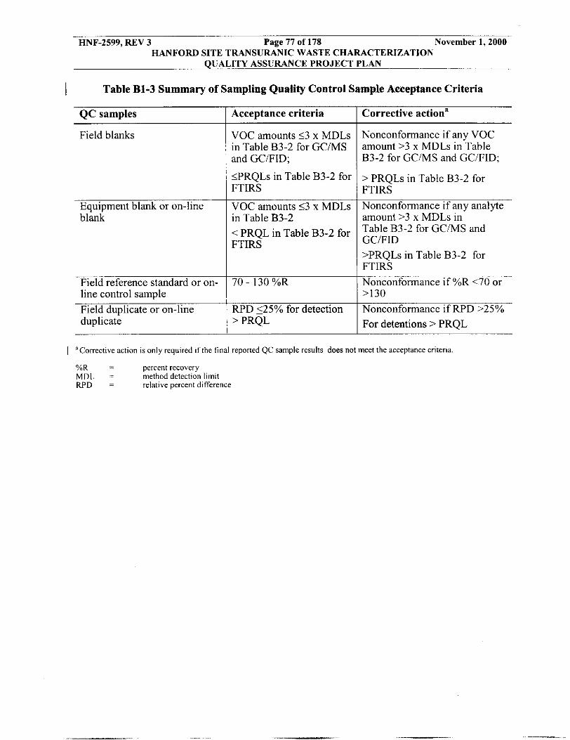
HNF-2599, REV 3 Page 71 of 178 November 1,2000 HANFORD SITE TRANSURANIC WASTE CHARACTERIZATION
QtJALITY ASSURANCE PROJECT PLAN
I Table B1-3 Summary of Sampling Quality Control Sample Aixeptaoce Criteria
QC samples
Field blanks
Equipment blank or on-line blank
Field reference standard or on- line control sample Field duplicate or on-line duplicate
Acceptance criteria
VOC amounts 53 x MDLs in Table B3-2 for GCMS and GCIFID;
5PRQLs in Table B3-2 for FTIRS
VOC amounts 53 x MDLs in Table B3-2 < PRQL in Table B3-2 for FTIRS
70 - I30 %R
RPD 525% for detection > PRQL
Corrective actiona
Nonconformance if any VOC amount >3 x MDLs in Table B3-2 for GCiMS and GC/FID;
> PRQLs in Table 83-2 for FTIRS Nonconformance if any analyte amount >3 x MDLs in Table B3-2 for GC/MS and GCIFID >PRQLs in Table B3-2 for FTIRS Nonconformance if %R <70 or >130 Nonconformance if RPD >25% For detentions > PRQL
I 'Corrective action is only required If the final reported QC sample rcsults does not meet the acceptance criteria
%R = percent recovery MDL = method detection limit RPD = relative percent difference

HNF-2599, REV 3 Page 78 of 178 November 1,2000 HANFORD SITE TRANSURANIC WASTE CHARACTERIZATION
QUALITY ASSURANCE PROJECT PLAN
Parameter
VOCS SVOCS Polychlorinated Biphenyls (PCBs) Metals
TABLE B1- 4 SAMPLE HANDLING REQUIREMENTS FOR HOMOGENEOUS SOLIDS AND
SOIL/GRAVEL
Maximum Holding Timeb Suggested Required Suggested Quantity' Preservation Container 15 grams Cool to 4" C Glass Vial' 14 Days Prepi40 Days Analyzed 50 grams Cool to 4" C Glass Jar" 14 Days Prepi40 Days Analyzed 50 g r a m Cool to 4" C Glass Jar' 14 Days PrepMO Days Analyze
10 grams Cool to 4' C Glass Jae 180 Daysh
'Quantity may be increased or decreased according to the requirements of the analytical laboratory, as long as the QAOs are met.
Holding time begins at sample collection (holding times are consistent with SW-846 requirements) 40-ml VOA vial or other appropriate containers shall have an airtight cap. 40-day holding time allowable only for methanol extract ~ 14-day holding time for non-extracted VOCs.
e Appropriate containers should be used and should have Teflon lined caps Analysis for PCBs is required only for waste streams in Waste Matrix Code S3220 (organics sludges). Polyethylene or polypropylene preferred, glass jar is allowable. Holding time for mercury analysis is 28 days.
Note: Preservation requirements in the most recent version of SW-846 may he used if appropriate For information only.

HNF-2599, REV 3 Page 79 of 178 November 1,2000 HANFORD SITE TRANSURANIC WASTE CHARACTERIZATION
QUALITY ASSURANCE PROJECT PLAN
y . L- --. ,
', 'k
HUMDtRER
.- 7

HNF-2599, REV 3 Page 80 of 178 November 1,2000 HANFORD SITE TRANSURANIC WASTE CHARACTERIZATION
QUALITY ASSURANCE PROJECT PLAN
I 11

HNF-2599, REV 3 Page 81 of 178 November 1,2000 HANFORD SITE TRANSURANIC WASTE CHARACTERIZATION
QUALITY ASSURANCE PROJECT PLAN
Figure B1-3a Example of Single Sampling Canister Assembly

HNF-2599, REV 3 Page 82 of 178 November 1,2000 HANFORD SITE TRANSURANIC WASTE CHARACTEMZATION
QUALITY ASSURANCE PROJECT PLAN
Figure B1-3b Example of Duplicate Sampling Canister Assembly
! 1 :
,_,' ,'

HNF-2599, REV 3 Page 83 of 178 November 1,2000 HANFORD SITE TRANSURANIC WASTE CHARACTERIZATION
QUALITY ASSURANCE PROJECT PLAN
Figurn Ria Rola(lanel Corlng Tod (light Welght AUW)
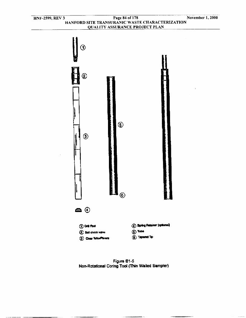
HNF-2599, REV 3 Page 84 of 178 November 1,2000 HANFORD SITE TRANSURANIC WASTE CHARACTERIZATION
QUALITY ASSURANCE PROJECT PLAN

HNF-2599, REV 3 Page 85 of 178 November 1,2000 HANFORD SITE TRANSURANIC WASTE CHARACTERIZATION
QUALITY ASSURANCE PROJECT PLAN
Use radiooraohv to determine1 verifv the matrix code
nrouo and estimate waste material narameter weiohts 1 Perform visual examination
Visually examine unopened
Waste bagslpackages
Perform a limited visual
unopened bagslpackages
Perform a full be determined without visual examination
onenino bans1
Confirm radioaraohv-indicated matrix code nroun
and determine waste material narameter weiohts
Open bagslpackages
- Determine matrix
code group and waste material parameter weights
I
Based on the results of visual examination calculate the percentage of
waste containers with incorrectly assigned matrix code group
Figure B1-6 Overall Programmatic Approach to Visual Examination

HNF-2599, REV 3 Page 86 of 178 November 1,2000 HANFORD SITE TRANSURANIC WASTE CHARACTERIZATION
QUALITY ASSURANCE PROJECT PLAN
Sample Matrix T ~ ~ M ~ . of Containers
Figure B1-7. Sample Chain of Custody Form (example only)
lampling Facility:
:ollection Date:
:ollection Time: Waste Container No.: COC No.:
;ampling Personnel (print name[s]):
;ampling Personnel Signature(s):
;ample Type: II Headspace Gas rl Homogeneous Solid n SoiliGravel
Preservative
~
4nalytlcal Laboratory:
Sample ID No. Collection DateiTime
ielinquished by I Received by signahueiorganization) (signahueiorganization)
Carrier:
Date Time
Final disposition of sample:
Sample removed from custody:
Signature:

HNF-2599, REV 3 Page 87 of 178 November 1,2000 HANFORD SITE TRANSURANIC WASTE CHARACTERIZATION
QtJALITY ASSURANCE PROJECT PLAN
B2 STATISTICAL METHODS USED IN SAMPLING AND ANALYSIS
TRU Project personnel use the following statistical methods for sampling and analysis of TRU waste, which is to be managed, stored, or disposed at WIPP. These statistical methods include methods for selecting waste containers for visual inspection, selecting retrievably stored waste containers for totals analysis, setting the upper confidence limit, and control charting for newly generated waste stream sampling.
B2-1 Approach for Statistically Selecting Waste Containers for Visual Examination
As a QC check on the radiographic examination of waste containers, TRU Project personnel statistically select a portion of the waste containers to be opened and visually examined in accordance with WMH-400, Section 7.1.4. The data from VE shall be used to
I verify the waste matrix code, waste material parameter weights, and absence of the prohibited items listed in Section B-lc, as determined by radiography.
TRU project personnel use the data obtained from the VE to determine, with acceptable confidence, the percentage of miscertified waste containers from the radiographic examination. Miscertified containers are those that radiography indicates meet the WIPP-WAC and Transuranic Package Transporter-I1 (TRUPACT-11) Authorized Methods for Payload Control (TRAMPAC) requirements, but VE indicates the containers do not meet these requirements. Miscertifications also include containers that are reassigned to a different Waste Matrix Code (see Section B3-4). The following assumptions are used to determine the number of containers, which must undergo VE:
0 Waste containers are randomly selected and examined to ensure that a representative sample of waste containers is obtained.
Only waste containers certified for compliance with WPP-WAC and TRAMPAC will be selected.
0
0 There is a definable finite population of waste containers for which the proportion miscertified is to be estimated.
0 The certification process is uniform for all waste containers and is unbiased regardless of the waste stream.
The radiography system is functioning properly and is operated by qualified personnel.
0
TRU Project personnel shall initially use an 11 percent miscertification rate to calculate the number of waste containers that shall be visually examined until a site-specific miscertification rate has been established. A site-specific miscertification rate will be established
11 percent miscertification rate. The results of this initial characterization shall then serve as the site-specific miscertification rate until reassessed annually as described below.
I by characterizing a lot of no less than 50 containers in a single Summary Category Group at the

HNF-2599, REV 3 Page 88 of 178 November 1,2000 HANFORD SITE TRANSURANIC WASTE CHARACTERIZATION
QUALITY ASSURANCE PROJECT PLAN
The site-specific miscertification rate shall be applied initially to each Summary Category Group to determine the number of containers in that Summary Category Group requiring VE, as specified in Table B2-1. However, a Summary Category Group-specific miscertification rate shall be determined when either six months have passed since radiographic characterization commenced on a Summary Category Group, or at least 50 percent of a given Summary Category Group has undergone radiographic characterization, whichever occurs first. The Summary Category Group shall then be subject to the VE requirements of this reevaluated Summary Category Group-specific miscertification rate to ensure that the entire Summary Category Group is appropriately characterized. Table B2-1 provides the number of waste containers per Summary Category Group that shall be visually examined for various miscertification rates and waste container population sizes using a hypergeometric sampling approach. A miscertification
calculated to be less than 1 percent. I rate of 1 percent will be used for any Summary Category Group specific miscertification rate
The site-specific miscertification rate shall be reassessed annually by calculating a drum- weighted average of all historic Summary Category Group-specific miscertification rates. Each Summary Category Group-specific miscertification rate shall be rounded off to the nearest integer value before being used to calculate the new site-specific miscertification rate. A miscertification rate of 1 percent for any site-specific miscertification rate calculated to be less than 1 percent shall be used
Table B2-I has been developed with the use of an EG&G Idaho, Inc., engineering design file (EG&G 1994). The number of waste containers requiring VE is based on a 90 percent confidence that the actual miscertification rate (for the population) is less than the 90 percent upper confidence level (UCL), and also an 80 percent confidence that the UCL will be less than 14 percent if the actual miscertification rate is the same as the targeted percent of miscertified waste containers (column heading of Table B2-1). Thus, there is only a 10 percent probability that the UCL will be below 14 percent in the case where the actual miscertification rate is 14 percent or greater. Also, there is only a 20 percent probability that the UCL will be above 14 percent in the case where the actual miscertification rate is the same as the targeted percent.
The hypergeometric approach to determining the number of containers to be visually examined is dependant upon the defined estimate of the allowable proportion of containers that were miscertified and information on previous percentages of containers that were miscertified. The rationale and details of this methodology are discussed below.
In a population of size N, there are M miscertified containers, so the true proportion of the miscertified containers in the population is M N = ptrue. Since ptrue (or M) is not known, ptrue shall be estimated by randomly sampling some of the containers. If in a sample of n containers, x are found to be miscertified, the sample estimate (j3) of the true population proportion ptrUe is:
(B2-1)

HNF-2599, REV 3 Page 89 of 178 November 1,2000 HANFORD SITE TRANSURANIC WASTE CHARACTERIZATION
QUALITY ASSURANCE PROJECT PLAN
This value is only an estimate, and as a result has some uncertainty associated with it. This uncertainty shall be quantified by calculating the upper one-sided (1- K ) percent confidence limit for p, defined as prlcL. This confidence limit gives the largest value the true proportion could take on and still have a “reasonable” chance (e.g., an ot = 0.10 probability) of producing x miscertified containers in a sample of n out of N. This upper confidence limit is calculated as:
(B2-2)
where MUcL is the smallest value of M such that the probability of observing x or fewer miscertified containers in a sample of size n is less than or equal to a. That is, it is the smallest value of M such that the following inequality is true:
(B2-3)
where each term in parentheses has the usual combinatorial interpretation. For example:
M! (:I = k! (M . k,! (B2-4)
Each term in the sum in Equation B2-3 is the hypergeometric probability of observing k miscertified containers in a sample size n from a population of size N in which there are M miscertified containers (and hence the population proportion of miscertified containers is p =MN). The value Mucl is obtained by substituting different values for M into Equation B2-3 until the smallest value satisfying the inequality is found.
Note that in Equation B2-3, the upper confidence limit is dependent on x, the number of miscertifications observed in the sample, as well as on n, the sample size. To obtain the required sample size, the values of x that are likely to be seen shall also need to be considered. Sample size that shall be visually examined shall be determined by setting a desired upper confidence limit value and then manipulating x and n in Equation B2-3.
WMH-400, Section 7. I .4 describes how waste containers are selected for VE. Each year, the number ofwaste containers to be visually examined is determined based on the number of waste containers that are expected to be certified and the previous year’s miscertification rate. Facility personnel visually examine the statistically selected portion of the waste containers.

HNF-2599, REV 3 Page 90 of 178 November 1,2000 HANFORD SITE TRANSURANIC WASTE CHARACTERIZATION
QUALITY ASSURANCE PROJECT PLAN
At a minimum, enough waste containers will be visually examined to achieve the level of confidence required by the QAPjP. VE requirements for all wastes are described in WMH-400, Section 7.1.3.
I B2-2 Approach for Selecting Waste Contalners €or Statistical Sampling
I B2-2a Statistical Selection of Containers for Total Analysis
The statistical approach for characterizing retrievably stored homogeneous solids and soiligravel waste using sampling and analysis relies on using AK to segregate waste containers into relatively homogeneous waste streams. Using AK, TRU Project personnel will classify the entire waste stream as hazardous or nonhazardous rather than individual waste containers. Individual waste containers serve as convenient units for characterizing the combined mass of waste from the waste stream of interest. Once segregated by waste stream, random selection and sampling of the waste containers followed by analysis of the waste samples is performed to ensure that the resulting mean contaminant concentration provides an unbiased representation of the true mean contaminant concentration for each waste stream. Random selection and analysis is performed in accordance with WMH-400, Section 7.1.4. The SPM will verify that the samples collected from within a waste stream were selected randomly.
An end use of analytical results for retrievably stored homogeneous solids and soiligravel is for assigning the EPA hazardous waste D-codes that apply to each TRU waste stream and to confirm AK. The D-codes are indicators that the waste exhibits the toxicity characteristic for specific contaminants under the RCRA. The RCRA-toxicity determination is made on the basis of sampling and analysis of waste streams and on whether or not the waste stream includes F-code wastes. If a waste stream includes one or more RCRA F-codes identified via AK, toxicity characteristic contaminants associated with the F-code waste(s) are not included in the RCRA-toxicity characteristic determination. That is, the F-codes take precedence over RCRA- toxicity D-code, and the waste stream is assumed hazardous regardless of the concentration. Therefore, toxicity characteristics contaminants associated with F-codes(s) for a waste stream will be omitted from all calculations for determining the number of containers to sample because these wastes streams are assumed to be hazardous. In addition, each toxicity characteristic contaminant associated with the F-code(s) will be excluded from evaluation of analytical results to determine D-codes. Contaminants of interest for the sampling, analysis, and RCRA-toxicity determination of a waste stream, excludes contaminants associated with F-codes that have been assigned to the waste stream.
The sampling and analysis strategy is illustrated in Figure B2-1. Preliminary estimates of the mean concentration and variance of each RCRA regulated contaminant in the waste is used to determine the number of waste containers to select for sampling and analysis. The preliminary estimates are made by obtaining a preliminary number of samples from the waste stream or from previous sampling from the waste stream. Preliminary estimates are based on samples from a minimum of five waste containers. Samples collected to establish preliminary estimates that are selected, sampled, and analyzed in accordance with applicable provisions of the QAPjP may be used as part of the required number of samples to be collected. TRU Project
I personnel determine the applicability of the preliminary estimates to the waste stream to he sampled. This determination is justified and documented by the SPM. The:,greliminary 6stimatm ape'&termimA in accordance with the following equatiobs:

NNF-2599, REV 3 Page 91 of 178 November 1,2000 HANFORD SITE TRANSURANIC WASTE CHARACTERIZATION
QUALITY ASSURANCE PROJECT PLAN
- I " n i = i
x = - - y x i (B2-5)
(B2-6)
where x is the calculated mean and s2 is the calculated concentration variance, n is the number of samples analyzed, xi is the concentration determined in the ith sample, and i is an index from 1 to n.
Based upon the preliminary estimates of x and sz for each chemical contaminant of concern, estimate the appropriate number of samples (n) to be collected for each contaminant
I using the following formulas from SW-846 (USEPA 1996).
--. . -

HNF-2599, REV 3 Page 92 of 178 November 1,2000 HANFORD SITE TRANSURANIC WASTE CHARACTERIZATION
QUALITY ASSURANCE PROJECT PLAN
The preliminary estimated concentration mean and associated variance for the contaminant of interest with the highest CV must be used to calculate the number of samples required, n, in accordance with the procedure described in (Cochran, 1977).
(B2-7)
Where:
no = the initial number of samples used to calculate the preliminary sample estimate. n = the calculated number of samples in the preliminary estimate. t2 = the 90th percentile for a t distribution with no-I degrees of freedom. RT = Regulatory Threshold of the contaminant (TC limit for toxicity characteristic wastes, PRQL for listed wastes)
The number of samples collected will be based upon the largest n calculated for each of the contaminants of concern. The actual number of samples collected is adjusted as necessary to ensure that an adequate number of samples are collected to allow for acceptable levels of completeness.
All calculations are rounded up to the nearest integer. A minimum of five containers will be sampled and analyzed in each waste stream. If there are less than the minimum or required number of containers in a waste stream, one or more containers are sampled more than once to obtain the samples of the waste. Otherwise, a container may only be selected for sampling one time,
The calculated total number of required waste containers is randomly sampled and analyzed by TRU project personnel. Waste container samples from the preliminary mean and variance estimates may be counted as part of the total number of calculated required samples if and only if:
. There is documented evidence that the waste containers for the preliminary estimate samples were selected in the same random manner as is chosen for the required samples.
. There is documented evidence that the method of sample collection in the preliminary estimate samples were identical to the methodology to be employed for the required samples.
. There is documented evidence that the method of sample analysis in the preliminary estimate samples were identical to the analytical methodology empfayed for the required samples.
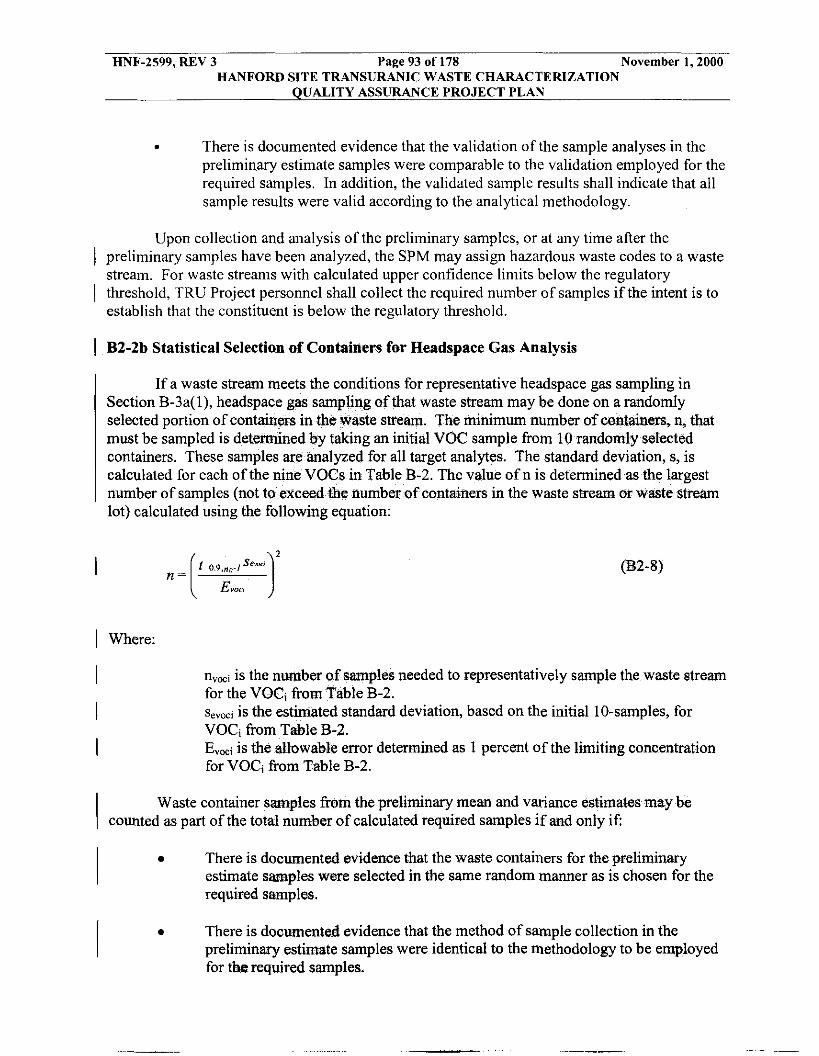
HNF-2599, REV 3 Page 93 of 178 November 1,2000 HANFORD SITE TRANSURANIC WASTE CHARACTERIZATION
QUALITY ASSURANCE PROJECT PLAN
. There is documented evidence that the validation of the sample analyses in the preliminary estimate samples were comparable to the validation employed for the required samples. In addition, the validated sample results shall indicate that all sample results were valid according to the analytical methodology.
Upon collection and analysis of the preliminary samples, or at any time after the I preliminary samples have been analyzed, the SPM may assign hazardous waste codes to a waste
stream. For waste streams with calculated upper confidence limits below the regulatory I threshold, TRU Project personnel shall collect the required number of samples if the intent is to
establish that the constituent is below the regulatory threshold.
I B2-2b Statistical Selection of Containers for Headspace Gas Analysis
If a waste stream meets the conditions for representative headspace gas sampling in at waste stream may be done o am. The minimum number of
1Y n, that
taking an initial VOC sample from 10 randomly selected containers. These samples are analyzed for all target analytes. The standard deviation, s, is calculated for each of the nine V number of samples (not to excee lot) calculated using the following equation:
in Table B-2. The value of n is determined as the largest number of containers in the waste stream or waste stream
1 Where:
I nv,, is the nu iber of samples n for the VOC, from Table B-2.
ded
(B2-8)
representatively sample th waste stre n
s,,,, is the estimated standard deviation, based on the initial 10-samples, for VOC, &om Table B-2. E,,, is the allowable error determined as 1 percent of the limiting concentration for VOC, from Table B-2.
I I
Waste container samples from the preliminary mean and variance estimates may be counted as part of the total number of calculated required samples if and only if:
0 There is documented evidence that the waste containers for the preliminary estimate samples were selected in the same random manner as is chosen for the required samples.
There is documented evidence that the method of sample collection in the preliminary estimate samples were identical to the methodology to be employed for the required samples.
I 0

HNF-2599, REV 3 Page 94 of 178 November 1,2000 HANFORD SITE TRANSURANIC WASTE CHARACTERIZATION
QUALITY ASSURANCE PROJECT PLAN
a There is documented evidence that the method of sample analysis in the preliminary estimate samples were identical to the analytical methodology employed for the required samples.
There is documented evidence that the validation of the sample analyses in the preliminary estimate samples were comparable to &e validation employed for the required samples. In addition, the validated samples results shall indicate that all sample results were valid according to the analytical methodology.
The mean and standard deviation calculated after sampling n containers can be used to calculate a UCL90 for each of the headspace gas VOCs using the methodology presented in Section B2-3b.
1 B2-3 Upper Confidence Limits for Statistical Sampling
I B2-3a Upper Confidence Limit for Statistical Solid Sampling
Upon completion of the required sampling, TRU Project personnel will determine the final mean and variance estimates and the UCL90 for the mean concentration for each contaminant in accordance with WMH-400. Section 7.1.4.
The observed sample n* shall he checked against the preliminary estimate for the number of samples (n) to be collected before proceeding, where n* is:
(82-9)
If the observed sample n* estimate results in greater than 20 percent more required samples than were originally calculated, then the additional samples required to fulfill the revised sample estimate shall be collected and analyzed. The determination of n* is an iterative process that continues until the difference between n* and the previous sample determination is less than 20 percent.
Once sufficient sampling and analysis has occurred, the waste characterization will proceed. The assessment will be made with 90 percent confidence. The UCLq0 for the mean concentration of each contaminant will be calculated in accordance with the following equation:
(B2-IO)
If the UCL90 for the mean concentration is less than the regulatory threshold limit, the I
waste stream will not be assigned the hazardous waste code for this contaminant. If the UCLg0 is greater than or equal to the regulatory threshold limit, the waste stream will be assigned the h a z d o w w a s t e code for this contaminant.

HNF-2599, REV 3 Page 95 of 178 November 1,2000 HANFORD SITE TRANSURANIC WASTE CHARACTERIZATION
QUALITY ASSURANCE PROJECT PLAN
The statistical tests described above are based on the assumption that the measured concentrations of each contaminant are normally distributed. This assumption is best verified by comparing the fit of the untransformed data to the fit after certain transformations using the Shapiro-Wilk or equivalent statistical test. If a transformation is required to achieve normal distribution, the transformed PRQL will also be calculated. The tests will then be performed the same as before, with the transformed data and PRQL being substituted into the equations. If 30 or more samples have been collected from the waste stream or waste stream lot, the Central Limit Theorem (CLT) may be applied, the distribution assumed to be approximately normal, and a transformation unnecessary. Actual numeric values for each analyte will be reported, if possible, whether or not the measurement is above or below the MDL. For those analyte concentrations reported as less-than-detectable, a suitable substitution (e.g., one-half the MDL) will be made. WMH-400, Section 7.1.4, addresses transformation of data to normal distribution (if needed) and treatment of less-than-detectable analytical results.
1 B2-3b Upper Confidence Limit for Statlstical Headspace Gas Sjunpliig
If a waste stream meets the conditions for representative headspace-gas sampling in Section B-3a( l), a UCL90 concentration for each of the headspace gas VOCs must be calculated from the sample data collected. The observed sample n* shall be checked against the estimate for the number of samples (n) to be collected before proceeding, where n* is:
(B2-11)
If the observed sample n* estimate r samples than were originally calculated, the sample estimate shall be collected and analyzed. that continues until the difference between n* and the pre 20 percent. Then, the UCL90 is calculated using equation 90 percent upper confidence VOC concentration, x is the calculated mean VOC concentration and s is the standard deviation. The value ka,n.l) is taken from T&le 9-2 of Chapter 9 of SW-846. The calculated U C b concentration for each headspace gas VOC will then be assigned to those containers in the waste stream not selected for headspace-gas sampling. If the calculated UCL90 concentration is less than the applicable MDL, the MDL for the VOC will be assigned to each unsampled container instead of the UCL90 concentration. When composite headspace gas sample results are used, the mean, standard deviation, and t-statistics are based on the number of samples analyzed rather than the number of drums sampled.
B2-4 Control Charting for Newly Generated Waste Stream Sampling
more required red to fulfill the revised
an iterative process le determination is less than this case, UCL90 is the
Significant process changes and process fluctuations associated with newly generated waste will be determined by TRU Project personnel using statistical process control (SPC) charting techniques as described in WMH-400, Section 7.1.4. These techniques require historical data for determining limits for indicator species and subsequent periodic sampling to

HNF-2599, REV 3 Page 96 of 178 November 1,2000 HANFORD SITE TRANSURANIC WASTE CHARACTERIZATION
QUALITY ASSlJRANCE PROJECT PLAN
assess process behavior relative to historical limits. SPC will be performed on waste prior to solidification or packaging for ease of sampling. If the limits are exceeded for any toxicity characteristic parameter, the waste stream will be recharacterized, and the characterization will be performed according to procedures listed in Table A-1.
A Shewhart control chart (Gilbert, 1987) is a control chart for means that can be used for checking whether current data are consistent with past data and whether shifts or trends in means have occurred. The control chart for means is constructed of a centertine and upper and lower control limits that are based on the mean and standard deviation of historical data for the process. If a current sample mean from the process lies within the limits, the process is said to be “in control,” or consistent with historical data. If the current mean exceeds the limits, the process has likely changed from historical periods, and is considered out of control.
Logical sets of historical data to be used for the construction of limits in this application are the data from the initial characterization of the waste stream, if available, from characterization of a different lot of the waste stream, or from a retrievably stored waste stream of the same type from the same process. At a minimum, the logical set will include ten representative sample values collected and analyzed from the newly generated waste stream. The data used for construction of the limits will be justified. The underlying assumptions for control charts are that the data are independent and normally distributed with constant mean p and constant variance 0’. The statistical tests for normality will be conducted and data transformation to normality performed, if necessary. Transformations will take place prior to any calculations that use the data.
Each limit will be constructed such that there is a 90 percent confidence that the true mean does not exceed a limit. One-sided control limits are used because once a waste stream has been determined to be RCRA-hazardous, the limit exceedance of interest is on the lower side; that is, when the process may become nonhazardous. Likewise, once a waste stream has been determined not to be RCRA hazardous, the limit exceedance of interest is on the upper side; that is, when the process may become RCRA hazardous. Whether or not exceeding the limit would result in a change in the RCRA-hazardous nature of the waste stream depends on how close the observed control limits are to RCRA limits.
Current process data will be collected and averaged for comparison to the control limit for the mean. The collection period and number of samples to be included in the average are dependent on the waste stream characteristics. A small number of samples will reflect more of the process variability and there will potentially be more limit exceedance. If two or three samples are collected for the mean in the required annual (or batch) sampling of a relatively homogeneous waste stream, limit exceedances may not occur. If the waste stream is less homogeneous, it will be necessary to collect more samples to meet the required confidence limit.
Periodically it will be necessary to update the control limit for a process. An update is performed that includes all historical data if there is no evidence of a trend in the process or a shift in the mean for the process. If there has been a shift in the mean, only more recent data that reflects the shift is used. Control limits are based on at least ten data points that are representative of the process and do not exhibit outliers or a trend with time.

HNF-2599, REV 3 Page 97 of 178 November 1,2000 HANFORD SITE TRANSURANIC WASTE CHARACTERIZATION
QUALITY ASSURANCE PROJECT PLAN
TABLE B2-1 NUMBER OF WASTE CONTAINERS REQUIRING VISUAL EXAMINATION
I
16
I6
Annual Number of Waste Containers per Summary Category Undergoing Characterization
21 27 37 46 64 81 123 171 257 416 701 1176 1500
27 21 37 46 64 90 123 172 266 441 795 1453 2000
50 or less
IO0
200
300
400
500
I000
I500
2000
Number of Waste Containers Requiring Visual Examination Based on Percent of Waste Containers Miscertified to WIPP-WAC by Radiography in Previous Year(s)
I%or 2% 3% 4% 5% 6% 7% 8% 9% 10% 1 1 % 12% 13% 14% or less greatcr
228 I 22 I 224 I 22 I 29” I 50
a Number of containers for the higher even-number percent of miscertified containers is used because an odd percent implies a noninteger number of containers are likely to be miscertified.

HNF-2599, REV 3 Page 98 of 178 November 1,2000 HANFORD SITE TRANSURANIC WASTE CHARACTERIZATION
QUALITY ASSURANCE PROJECT PLAN
Yes MEAN < RTL
SEGREGATE WASTE CONTAINERS INTO WASTE STREAMS
1 DETERMINE USEPA HAZARDOUS WASTE F-CODES
AND CONTAMINANTS OF INTEREST FOR DETERMINING RCRA TOXICITY
CHARACTERISTICS
CLASSIFY WASTE STREAM AS NONHAZARDOUS FOR THIS
CONTAMINANT
OBTAIN RELIMINARY ESTIMATES OF MEAN AND VARIANCE FOR EACH CONTAMWANT OF
INTERSEST, AND DETERMINE CONTAMINANT OF INTEREST WITH HIGHEST COEFFICIENT OF
CALCULATE NUMBER OF SAMPLES AND ANALYSES REQUIRED FOR CONTAMINANT WITH HIGHEST
COEFFICIENT OF VARIATION
1 RANDOMLY SAMPLE AND ANALYZE THE NUMBER OF ADDITIONAL REQUIRED WASTE CONTAINERS
I CALCULATE UCLg0 FOR MEAN OF EACH CONTAMINANT
1 . CLASSIFY WASTE STREAM AS
HAZARDOUS FOR THIS
Figure B2-1 Statistical Approach to Sampling and Analysis of Waste Streams of Retrievably Stored
Homogenous Solids and Solid/Gravel

HNF-2599, REV 3 Page 99 of 178 November 1,2000 HANFORD SITE TRANSURANIC WASTE CHARACTERIZATION
QUALITY ASSURANCE PROJECT PLAN
B3 OUALITY ASSURANCE OBJECTIVES FOR WASTE CHARACTERIZATION AMPL LING AND ANALYTICAL METHODS
B3-1 Validation Methods
Facility quality assurance officers (FQAOs) and the SQAO didate data (qualitative quantitative) to ensure that data used for WIPP compliance programs are of known and acceptable quality. Validation includes a quantitative determination of precision, accuracy,
d
completeness, and method detection limit (as appropriate) for analytical data (VOC data and total VOC, SVOC, and metals data). Quantitative determinations are calculated in accordance with equations 3-1 through 3-9 below. TRU Project personnel compare the quantitative determinations to the QAOs specified in this section.
The qualitative data or descriptive information generated by radiography and VE is not amenable to statistical data quality analysis. However, radiography and VE are complementary techniques yielding similar data for determining the Waste Matrix Code Group and waste material parameter weights of waste present in a waste container. Therefore, VE results will be used to verify the Waste Matrix Code Group and waste material parameter weights determined by radiography. The Waste Matrix Code Group is determined and waste material parameter weights are estimated to verify that the container is properly included in the appropriate waste stream. The SQAO uses VE results to verify the Waste Matrix Code Group and waste material parameter weights determined by radiography, as described in Section B1-1 of the QAPjP.
Sampling personnel ensure sample representativeness through proper implementation of I sampling procedures. Representativeness of waste containers from waste streams subject to VE
and homogeneous solids and soil/gravel sampling and analysis are validated through documentation that a true random sample was collected. The SPM documents that the selected waste containers from within a waste stream were randomly selected in accordance with the requirements of Section B2.
Data validation will be used to assess the quality of waste characterization data collected based upon project precision, accuracy, completeness, comparability, and representativeness objectives. These objectives are described below.
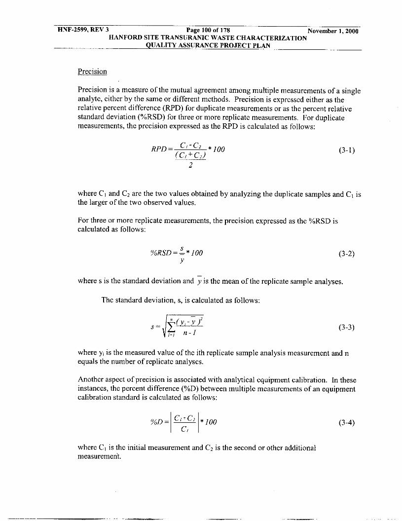
November 1,2000 HNF-2599, REV 3 Page 100 of 178 HANFORD SITE TRANSURANIC WASTE CHARACTERIZATION
QUALITY ASSURANCE PROJECT PLAN
Precision
Precision is a measure of the mutual agreement among multiple measurements of a single analyte, either by the same or different methods. Precision is expressed either as the relative percent difference (RPD) for duplicate measurements or as the percent relative standard deviation (%RSD) for three or more replicate measurements. For duplicate measurements, the precision expressed as the RPD is calculated as follows:
where CI and Cz are the two values obtained by analyzing the duplicate samples and C, is the larger of the two observed values.
For three or more replicate measurements, the precision expressed as the %RSD is calculated as follows:
S %RSD= = * 100
Y (3-2)
where s is the standard deviation and is the mean of the replicate sample analyses.
The standard deviation, s, is calculated as follows:
where y, is the measured value of the ith replicate sample analysis measurement and n equals the number of replicate analyses.
Another aspect of precision is associated with analytical equipment calibration. In these instances, the percent difference (%D) between multiple measurements of an equipment calibration standard is calculated as follows:
where CI is the initial measurement and CZ is the second or other additional measurement,
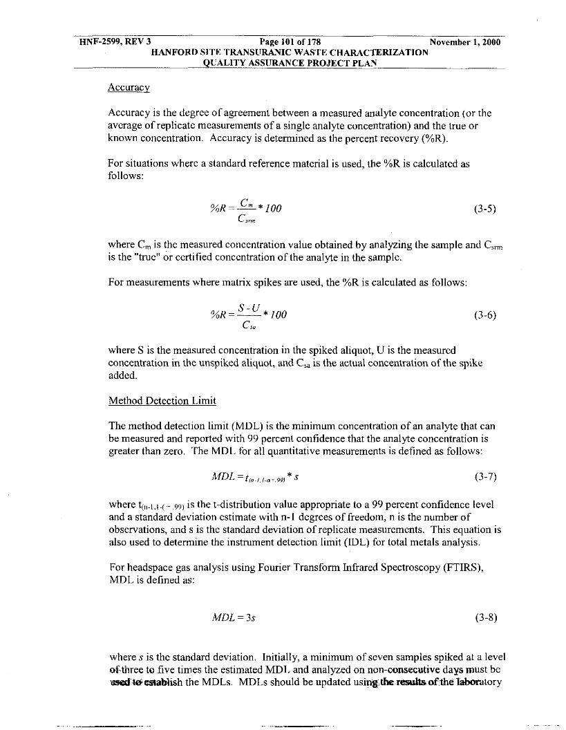
HNF-2599, REV 3 Page 101 of 178 November 1,2000 HANFORD SITE TRANSURANIC WASTE CHARACTERIZATION
QUALITY ASSURANCE PROJECT PLAN
Accuracy
Accuracy is the degree of agreement between a measured analyte concentration (or the average of replicate measurements of a single analyte concentration) and the true or known Concentration. Accuracy is determined as the percent recovery (%R).
For situations where a standard reference material is used, the %R is calculated as follows:
%R=- Cm * 100 CS,
(3-5)
where C, is the measured concentration value obtained by analyzing the sample and C,, is the "true" or certified concentration of the analyte in the sample.
For measurements where matrix spikes are used, the %R is calculated as follows:
where S is the measured concentration in the spiked aliquot, U is the measured concentration in the unspiked aliquot, and C,, is the actual concentration of the spike added.
Method Detection Limit
The method detection limit (MDL) is the minimum concentration of an analyte that can be measured and reported with 99 percent confidence that the analyte concentration is greater than zero. The MDL for all quantitative measurements is defined as follows:
where t(".,,,.(= .99) is the t-distribution value appropriate to a 99 percent confidence level and a standard deviation estimate with n-1 degrees of freedom, n is the number of observations, and s is the standard deviation of replicate measurements. This equation is also used to determine the instrument detection limit (IDL) for total metals analysis.
For headspace gas analysis using Fourier Transform Infrared Spectroscopy (FTIRS), MDL is defined as:
MDL = 3s (3-8)
where s is the standard deviation. Initially, a minimum of seven samples spiked at a level of three to five times the estimated MDL and analyzed on non-consecutive daysmust be d ' W establish the MDLs. MDLs should be updated usirpg,tlLe resultp ofthe laboratory

HNF-2599, REV 3 Page 102 of 178 November 1,2000 HANFORD SITE TRANSURANIC WASTE CHARACTERIZATION
QUALITY ASSURANCE PROJECT PLAN
control sample or on-line control samples. Currently, Hanford does not have FTIRS capability.
Completeness
Completeness is a measure of the amount of valid data (e.g., data that meet all QA/QC requirements) obtained from the overall measurement system compared to the amount of data collected and submitted for analysis. Completeness is expressed as the number of samples analyzed with individual target analytes achieving valid results as a percent of the total number of samples submitted for analysis. Completeness, expressed as the percent complete, is calculated as follows:
I
V %C = - * 100
n (3-9)
where V is the number of valid analytical results obtained, and n is the number of samples submitted for analysis.
Comparabilitv
Comparability is the degree to which one data set can be compared to another. Facility personnel ensure that data generated at different facilities over the lifetime of the project are comparable through the use of standardized approved testing, sampling, and analytical techniques, and by meeting the QAOs specified in this section.
The comparability of waste characterization data will be ensured through the use of data usability criteria. Data usability criteria will be consistently established and used to assess the usability of analytical and testing data. The criteria will address, as appropriate, the following:
0 Definition or reference of criteria used to define and assign data qualifier flags based on QAOs.
0 Criteria for assessing the usability of data impacted by matrix interferences.
Criteria for assessing the usability of data based upon positive and negative bias as indicated by quality control data, of data qualifiers, and qualifier flags.
Criteria for assessing the usability of data due to:
0
0
Severe matrix effects - Misidentification of compounds . Gross exceedance of holding times
Failure to meet calibration or tune criteria, and Criteria for assessing the usability of data that does not meet minimum detection limit requirements.
-

HNF-2599, REV 3 Page 103 of 178 November 1,2000 HANFORD SITE TRANSURANIC WASTE CHARACTERIZATION
QUALITY ASSURANCE PROJECT PLAN
Representativeness
Representativeness is the degree to which sample data represent a characteristic of a population, parameter variations at a sampling point, or an environmental condition. Representativeness is a qualitative parameter that concerns the proper design of the sampling program.
Representativeness of waste containers from waste streams subjected to VE and homogeneous solids and soiligravel sampling and analysis will be validated, through documentation, that a true random sample with an adequate population was collected. Since representativeness is a quality characteristic that expresses the degree to which a sample or group of samples represents the population being studied, the random selection of waste containers ensures representativeness on a program level. The SPM will document that the selected waste containers from within a waste stream were randomly selected. TRU Project sampling personnel will verify that proper procedures are followed to ensure that samples are representative of the waste contained in a particular waste container or a waste stream.
Nonconformance to Data Ouality Objectives (DOO)
For any nonadministrative nonconformance related to applicable requirements specified in this document which are first identified at the SPM signature release level (e.g., a failure to meet a DQO), a written notification will be sent to CAO within five calendar days of identification and a nonconformance report will be issued and submitted to CAO within thirty calendar days of identification of the incident in accordance with WMH-400, Section 1.3.2. A corrective action, which remedies the nonconformance, will be implemented prior to shipping the waste to WIPP in accordance with WMH-400, Section 1.3.3, “TRU Corrective Action Reporting and Control” (see Table A-1).
Identification of Tentativelv Identified Compounds
In accordance with SW-846 (USEPA 1996) convention, identification of compounds detected by gas GCiMS methods that are not on the list of target analytes will be reported. Headspace gas, volatile analysis (TCLPiTotals), and semi-volatile (TCLPiTotals) will be subject to tentatively identified compound (TIC) reporting. These TlCs for GCiMS methods are identified in accordance with the following SW-846 criteria:
e
I
The relative concentration of the TIC is > 10% of the concentration of the nearest internal standard.
I
0 Relative intensities of major ions in the reference spectrum (ions greater than I
I
I O percent of the most abundant ion) should be present in the sample spectrum.
I 0
.I
The relative intensities of the major ions should agree within & 20 percent.
Molecular ions present in the reference spectrum should be present in the sample sp-.
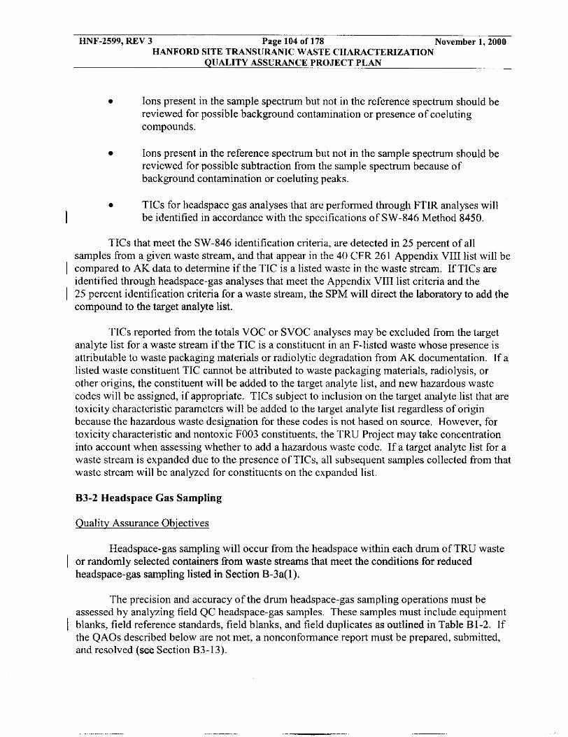
HNF-2599, REV 3 Page 104 of 178 November 1,2000 HANFORD SITE TRANSURANIC WASTE CHARACTERIZATION
QUALITY ASSURANCE PROJECT PLAN
Ions present in the sample spectrum but not in the reference spectrum should he reviewed for possible background contamination or presence of coeluting compounds.
Ions present in the reference spectrum hut not in the sample spectrum should be reviewed for possible subtraction from the sample spectrum because of background contamination or coeluting peaks.
TICs for headspace gas analyses that are performed through FTIR analyses will be identified in accordance with the specifications of SW-846 Method 8450. I
TICs that meet the SW-846 identification criteria, are detected in 25 percent of all samples from a given waste stream, and that appear in the 40 CFR 261 Appendix VI11 list will be
identified through headspace-gas analyses that meet the Appendix VI11 list criteria and the
compound to the target analyte list.
I compared to AK data to determine if the TIC is a listed waste in the waste stream. If TICS are
I 25 percent identification criteria for a waste stream, the SPM will direct the laboratory to add the
TICs reported from the totals VOC or SVOC analyses may be excluded from the target analyte list for a waste stream if the TIC is a constituent in an F-listed waste whose presence is attributable to waste packaging materials or radiolytic degradation from AK documentation. If a listed waste constituent TIC cannot be attributed to waste packaging materials, radiolysis, or other origins, the constituent will be added to the target analyte list, and new hazardous waste codes will be assigned, if appropriate. TICs subject to inclusion on the target analyte list that are toxicity characteristic parameters will be added to the target analyte list regardless of origin because the hazardous waste designation for these codes is not based on source. However, for toxicity characteristic and nontoxic F003 constituents, the TRU Project may take concentration into account when assessing whether to add a hazardous waste code. If a target analyte list for a waste stream i s expanded due to the presence of TICS, all subsequent samples collected from that waste stream will be analyzed for constituents on the expanded list.
B3-2 Headspace Gas Sampling
Qualitv Assurance Objectives
Headspace-gas sampling will occur from the headspace within each drum of TRU waste I or randomly selected containers from waste streams that meet the conditions for reduced
headspace-gas sampling listed in Section B-3a(l).
The precision and accuracy of the drum headspace-gas sampling operations must be assessed by analyzing field QC headspace-gas samples. These samples must include equipment
I blanks, field reference standards, field blanks, and field duplicates as outlined in Table B1-2. If the QAOs described below are not met, a nonconformance report must be prepared, submitted, and resolved (see Section B3-13).

HNF-2599, REV 3 Page 105 of 178 November 1,2000 HANFORD SITE TRANSURANIC WASTE CHARACTERIZATION
QUALITY ASSURANCE PROJECT PLAN
TRU Project sampling personnel collect field QC headspace gas samples for analysis at the frequency specified in Section B1-1 to demonstrate that QAOs have been met. Table B3-2 lists the required VOC analytes for each type of headspace-gas sample collected.
TRU Project sampling personnel with the FQAO prepare, submit, and resolve an NCR if final, reported QC sample results do not meet acceptance criteria. DO-080-009 and WMH-400, Section 8.1.8, "Data Management for Headspace Gas Samples" (see Table A-I), identify the methods used to demonstrate compliance with the QAOs. In accordance with DO-080-009 and WMH-400, Section 8.1.8, sampling personnel ensure that the following requirements are met.
Precision
The collection of field duplicates simultaneously or sequentially into SUMMATM canisters, or equivalent canisters, manually or by use of a sequential manifold for determination of VOCs is used to assess the precision of headspace-gas sampling and analysis. Analytical personnel calculate the RPD for the canister field duplicates and initiate corrective action if the RPD exceeds 25, for detections reported in both samples > PRQL.
I
Accuracy
Collection of a field reference standard into a SUMMATM canister, or equivalent canister, is done to assess the accuracy of headspace-gas sampling and analysis. The %R is calculated for the canister field reference standards, initiating corrective action if the %R of the field reference standard is less than 70 or greater than 130. A field reference standard must be collected at a frequency specified in Table B1-2 depending on manifold or direct canister sampling method.
Field blanks must also be collected at a frequency of 1 field blank for every 20 drums or sampling batch to assess possible contamination in the headspace-gas sampling method. Equipment blanks must also be collected at the frequencies specified in Table B1-2 to assess possible contamination in the equipment cleaning method.
Corrective actions must be taken if the blank exceeds three times the MDLs from
I
I I table B3-2 for any of the compounds listed.
Completeness
TRU Project personnel will conduct sufficient headspace-gas sampling to ensure a minimum 90 percent completeness where completeness is defined as the number of valid samples as a percentage of the total number of samples collected. A valid sample is defined as a sample collected in accordance with approved sampling procedures and a drum that was properly prepared for sampling. The FQAO and the SQAO evaluate the importance of any lost or contaminated headspace-gas samples and initiate corrective action, as appropriate. DO-080-009 describes how sampling personnel document any nonroutine events or occurrences that may affect the quality of the headspace-gas sample collected
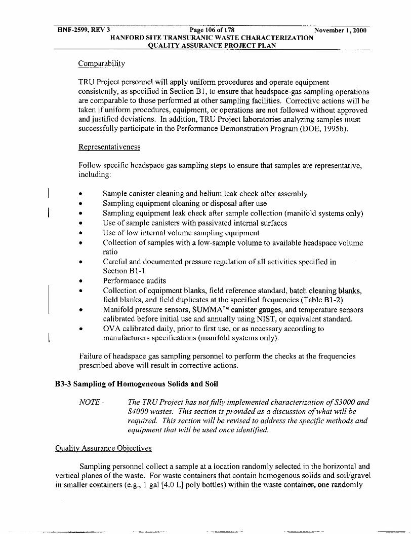
HNF-2599, REV 3 Page 106 of 178 November 1,2000 HANFORD SITE TRANSURANIC WASTE CHARACTERIZATION
QUALITY ASSURANCE PROJECT PLAN
Comuarability
TRU Project personnel will apply uniform procedures and operate equipment consistently, as specified in Section B1, to ensure that headspace-gas sampling operations are comparable to those performed at other sampling facilities. Corrective actions will be taken if uniform procedures, equipment, or operations are not followed without approved and justified deviations. In addition, TRU Project laboratories analyzing samples must successfully participate in the Performance Demonstration Program (DOE, 1995b).
Representativeness
Follow specific headspace gas sampling steps to ensure that samples are representative, including:
I 0
0 I
0
I
Sample canister cleaning and helium leak check after assembly Sampling equipment cleaning or disposal after use Sampling equipment leak check after sample collection (manifold systems only) Use of sample canisters with passivated internal surfaces Use of low internal volume sampling equipment Collection of samples with a low-sample volume to available headspace volume ratio Careful and documented pressure regulation of all activities specified in Section B1-1 Performance audits Collection of equipment blanks, field reference standard, batch cleaning blanks, field blanks, and field duplicates at the specified frequencies (Table B1-2) Manifold pressure sensors, SUMMATM canister gauges, and temperature sensors calibrated before initial use and annually using NIST, or equivalent standard. OVA calibrated daily, prior to first use, or as necessary according to manufacturers specifications (manifold systems only).
Failure of headspace gas sampling personnel to perform the checks at the frequencies prescribed above will result in corrective actions.
B3-3 Sampling of Homogeneous Solids and Soil
NOTE - The TRU Project has not fully implemented characterization of S3000 and S4000 wastes. This section is provided as a discussion of what will be required. This section will be revised to address the specific methods and equipment that will be used once identified.
Oualitv Assurance Obiectives
Sampling personnel collect a sample at a location randomly selected in the horizontal and vertical planes of the waste. For waste containers that contain homogenous solids and soil/gavel in smaller containers (e.g., 1 gal [4.0 L] poly bottles) within the waste container. one randomly

HNF-2599, REV 3 Page 107 of 178 November 1,2000 HANFORD SITE TRANSURANIC WASTE CHARACTERIZATION
QUALITY ASSUFUNCE PROJECT PLAN
chosen smaller container must be sampled from each drum. WMH-400, Section 7.1.3 identifies the methods (summarized below) used to demonstrate compliance with the QAOs.
Precision
TRU Project personnel will collect and sample field duplicates (e.g., co-located cores or co-located samples as described in Section B1-2b(l)) once per sampling batch or once per week during sampling operations, whichever is more frequent. A sampling batch is a suite of homogenous solids and soil/gravel samples collected consecutively using the same sampling equipment within a specific time period. A sampling batch can be up to 20 samples (excluding field QC samples), all of which must be collected within 14 days of the first sample in the batch. The SQAO will calculate and report the RPD between co-located core/samples.
The recommended method for establishing acceptance criteria for co-located cores and co-located samples is the F-test method because the F-Test: 1) does not require potentially arbitrary groupings into batches, 2) is based on exact distributions, and 3) is more likely to detect a change in the process. When a sufficient number of samples are collected (25 to 30 pairs of co-located cores or samples), control charts of the RPD will be developed for each constituent and for each waste matrix or waste type (e.g., pyrochemical salts or organic sludges). The limits for the control chart will be three standard deviations above or below the average RPD. Once constructed, RPDs for additional co-located pairs will be compared with the control chart to determine whether or not the co-located cores are acceptable. Periodically, the control charts will be updated using all available data (see Section B2-4.)
The statistical test will involve calculating the variance for co-located cores and samples by pooling the variances computed for each pair of duplicate results. The variance for the waste stream will be computed excluding any data from drums with co-located cores because the test requires the variance estimates to be independent. All data must be transformed to normality prior to computing variances and performing the test. The test hypothesis is evaluated using the F distribution and the method for testing the difference in variances.
Accuracy
TRU Project personnel will comply with methods and requirements described in Section B1-2 to minimize sample degradation and maximize sampling accuracy. Because waste containers containing homogeneous solids and soiligravel with known quantities of analytes are not available, sampling accuracy cannot be determined.
HNF-2599, REV 3 Page 108 of 178 November 1,2000 HANFORD SITE TRANSURANIC WASTE CHARACTERIZATION
QUALITY ASSURANCE PROJECT PLAN
Sampling accuracy as a function of sampling cross-contamination will be measured. Equipment blanks will be collected at a frequency of once per equipment cleaning batch. Corrective actions must be taken if the blank exceeds three times the MDLs (PRDLs for metals) listed for any of the compounds or analytes listed in Tables B3-4, 83-6, and B3-8. Equipment blanks will be collected from the following equipment types:
0 Fully assembled coring tools,
Completeness
Completeness is measured by completeness by calculating the number of valid samples collected as a percent of the total number of samples collected and achieve a minimum 90 percent completeness. A valid sample is any sample that is collected from a randomly selected drum using randomly selected horizontal and vertical planes in accordance with approved sampling methods. The FQAO and SQAO evaluate the importance of any lost or contaminated samples and determine whether corrective action is appropriate. WMH-400, Section 7.1.3, describes the process for documenting any nonroutine events or occurrences that may affect the quality of the samples collected.
Comparability
To ensure that sampling operations are comparable, TRU Project personnel will apply uniform procedures and measurement units and use sampling equipment consistently. Collection and evaluation of collocated samples is described in Section B1-2. Consistent application of data usability criteria will also ensure comparability. In addition, the TRU Project laboratories analyzing samples will successfully participate in the PDP (DOE,
Liners cleaned separately from coring tools, and Miscellaneous sampling equipment that is reused (bowls, spoons, chisels, etc.).
1995c).
Representativeness
The following are specific steps to ensure the representativeness of samples for both waste containers and smaller containers:
0
Cleaning of sampling tools and equipment before sampling Coring the entire depth of the waste.

HNF-2599, REV 3 Page 109 of 178 November 1,2000 HANFORD SITE TRANSURANIC WASTE CHARACTERIZATION
QUALITY ASSURANCE PROJECT PLAN
The core collected must have a length greater than or equal to 50 percent of the depth of the waste. This is called the core recovery and is calculated as follows:
Y Core recovery (percent) = - x 100 X
where x = the depth of the waste in the container y = the length of the core collected from the waste.
Representativeness is further ensured by visually examining the sample to verify minimal waste disturbance, and document the observation (e.g., undisturbed, cracked, pulverized) in sampling records. Sampling operations and tool selection are designed to minimize alteration of the in-place waste characteristics.
If core recovery is less than 50 percent of the depth of the waste, a second coring location will be randomly selected. The core with the best core recovery will be used for sample collection.
One randomly selected container within a drum will be chosen if the drum contains individual waste containers.
B3-4 Radiography
If the QAOs described below are not met, then corrective action shall be taken as appropriate for the deficiency.
Ouality Assurance Obiectives
NDE radiography procedures identify the methods used to meet QAOs and the corrective actions to be taken when QAOs are not met. The objective of radiography for the TRU Project is
each waste container and to estimate each waste material parameter weight (Table B3-1).
Data to meet these objectives must be obtained from an audiohideotaped (or equivalent media) scan provided by trained radiography operators. Results must also be recorded on a radiography data form. The precision, accuracy, completeness, and comparability objectives for radiography data are presented below.
Precision
The qualitative determinations made during radiography do not lend themselves to statistical evaluation of precision because of the qualitative nature of the inspection. Howeuem,&graphy operators can provide estimated inventories and wei&;lsof,waste
I to verify the Waste Matrix Code Group for the waste stream and identify prohibited items for

HNF-2599, REV 3 Page 110 of 178 November 1,2000 HANFORD SITE TRANSURANIC WASTE CHARACTERIZATION
QUALITY ASSURANCE PROJECT PLAN
items in a waste container. As a measure ofprecision, the SQAO will calculate and report the RPD between the estimated waste material parameter weights as determined by radiography and these same parameters as determined by VE. Additionally, the precision of radiography is verified prior to use by tuning precisely enough to demonstrate compliance with QAOs through viewing an image test pattern.
Accuracy
The accuracy with which the matrix parameter category is assigned is determined by visually examining a statistically selected random portion of waste containers. In accordance with the requirements of Section B2-1, the SQAO calculates and reports the miseertification rate of waste containers that require assignment to a different Waste Matrix Code or are found to contain prohibited items after VE as a measure of radiography accuracy. The miseertification rate will be used to determine the number of drums subject to confirmatory VE.
Completeness
The completeness QAO is met by documenting radiography or VE for 100 percent of the waste containers in the project. All audioivideotapes (or equivalent media) and radiography data forms will be subject to validation in accordance with Section B3-10.
Comparabilitv
Standardized radiography procedures and qualifications of operators are used in accordance with requirements to enhance the comparability of radiography data from different sites.
I
I B3-5 Headspace Gas Volatile Organic Compound Analysis
Ouality Assurance Objectives
Table B3-2 lists the QAOs for headspace gas VOC analysis. The specified QAOs represent the required quality of data necessary to draw valid conclusions regarding program objectives. Program required limits, such as the program required quantitation limits (PRQL) associated with VOC analysis, are specified to ensure that the analytical data collected satisfy the requirements of all data users. A summary of the quality control samples and the associated acceptance criteria is included in Table B3-3. Key data quality indicators are defined below.
Precision
Precision will be assessed by analyzing laboratory duplicates, replicate analyses of laboratory-control samples (LCSLCSD), and PDP blind-audit samples. Results from measurements on these samples must be compared to the criteria listed in Table B3-2. These QC measurements will be used to demonstrate acceptable method performance and to trigger corrective action when control limits are exceeded.
I

HNF-2599, REV 3 Page 111 of 178 November 1,2000 HANFORD SITE TRANSURANIC WASTE CHARACTERIZATION
QUALITY ASSURANCE PROJECT PLAN
Accuracy
Accuracy defined as %R will be assessed for the laboratory operations by analyzing PDP blind-audit samples and laboratory-control samples (LCS). Results from these measurements must be compared to the criteria listed in Table B3-2. These QC measurements will be used to demonstrate acceptable method performance and to trigger corrective action when control limits are exceeded.
I
Calibration
GUMS tune, initial calibrations, and continuing calibration verifications will be performed and evaluated using the procedures and criteria specified in Table B3-3 These criteria will be used to demonstrate acceptable instrument performance and calibration and to trigger corrective action when control limits are exceeded.
Method Detection Limit
MDLs will be expressed in nanograms for VOCs and must be less than or equal to those listed in Table B3-2. MDLs will be determined based on the method described in Section B3-2. The detailed procedures for MDL determination will be included in laboratory procedures.
Program Required Ouantitation Limit
TRU Project laboratories must demonstrate the capability to quantitate analytes at or below the PRQLs given in Table B3-2. Laboratories will set the concentration of at least one calibration standard below the PRQL. The detailed procedures for PRQL demonstration are included in laboratory procedures.
Comuleteness
Laboratory completeness will be expressed as the number of samples analyzed with valid results as a percent of the total number of samples submitted for analysis. A composited sample is treated as one sample for the purposes of completeness because only one sample is run through the analytical instrument. Valid results are defined as results that meet the data usability criteria based on application of the quality control criteria specified in Tables B3-2 and B3-3; and meet the detection limit, calibration representativeness, and comparability criteria within this section. In addition, the laboratories shall meet the completeness criteria specified in Table B3-2.
Comparability
VOC analysis will achieve comparability by using standardized methods and traceable standards and by successful participation in the PDP (DOE, 1995b).
I I
I
... -.

HNF-2599, REV 3 Page 112 of 178 November 1,2000 HANFORD SITE TRANSURANIC WASTE CHARACTERIZATION
QUALITY ASSURANCE PROJECT PLAN
Representative
Representativeness for VOC analysis will be achieved by collecting sufficient numbers of samples using clean sampling equipment that does not introduce sample bias. Samples must be collected as described in Section B1.
The FQAO is responsible for monitoring the results of these measurements and determining whether the precision, accuracy, and completeness criteria listed in Table B3-2 have been met. The FQAO also evaluates performance and decides whether corrective action should be initiated based on the results of the precision, accuracy, and completeness calculations.
B3-6 Total Volatile Organic Compound Analysis
NOTE - Hunford has not fully implemented characterization ofS3000 and S4000 waste. This section is provided as a discussion of what will be required and will be revised to address the speciffc requirements once identified. I
Oualitv Assurance Obiectives
The development of DQOs specifically for this program has resulted in the QAOs listed in Table B3-4. The specified QAOs represent the required quality of data necessary to draw valid conclusions regarding program objectives. Program limits required, such as the PRQL associated with VOC analysis, are specified to ensure that the analytical data collected satisfy the requirements of all data users. Key data-quality indicators for laboratory measurements are defined below.
Precision
Precision will be assessed by analyzing laboratory duplicates or matrix spike duplicates, replicate analyses of laboratory control samples, and PDP blind-audit samples. Results from measurements on these samples must be compared to the criteria listed in Table B3-4. These QC measurements will be used to demonstrate acceptable method performance and to trigger corrective action when control limits are exceeded.
Accuracv
Accuracy defined as %R will be assessed for the laboratory operations by analyzing laboratory control samples, matrix spikes, surrogate compounds, and PDP blind-audit samples. Results from these measurements for matrix spikes samples must be compared to the %R criteria listed in Table B3-4. Results for surrogates and internal standards are evaluated as specified in the SW-846 method (USEPA 1996) or Table B3-5. These QC measurements will be used to demonstrate acceptable method performance and to trigger corrective action when control limits are exceeded.
Laboratory blanks will be assessed to determine possible laboratory contamination and are evaluated as specified in Table B3-5. These QC measurements will be used to
I

HNF-2599, REV 3 Page 113 of 178 November 1,2000 HANFORD SITE TRANSURANIC WASTE CHARACTERIZATION
QUALITY ASSURANCE PROJECT PLAN
demonstrate acceptable levels of laboratory contamination and to trigger corrective action when control limits are exceeded.
Calibration
GUMS Tunes, initial calibrations, and continuing calibration will be performed and evaluated using the procedures and criteria specified in Table B3-5 and the SW-846
and to trigger corrective action when control limits are exceeded.
Method Detection Limit
MDLs will be expressed in milligrams per kilogram (mgikg) for VOCs and must be less than or equal to those listed in Table B3-4. The detailed procedures for MDL determination will be included in laboratory procedures.
Promam Required Ouantitation Limit
TRU Project laboratories must demonstrate the capability to quantitate analytes in samples at or below the PRQLs given in Table B3-4. The laboratory will set the concentration of at least one calibration standard below the PRQL. The detailed procedures for PRQL demonstration will be included in laboratory procedures.
Completeness
Laboratory completeness will be expressed as the number of samples analyzed with valid results as a percent of the total number of samples submitted for analysis. Valid results are defined as results that meet the data usability criteria based upon application of the quality control criteria specified in Tables B3-4 and B3-5 and meet the calibration, detection limit, representativeness, and comparability criteria within this section. The laboratory shall meet the completeness criteria specified in Table B3-4.
Comparability
The laboratory will achieve comparability by using standardized SW-846 sample preparation and methods that meet the QAO requirements in Tables B3-4 and B3-5, traceable standards, and by successfully participating in the PDP. The laboratory may use the most recent version of SW-846. Any changes to SW-846 methodology that result in the elimination of sample preparation or analytical method used must be addressed as a corrective action to address the comparability of data before and after the SW-846 modification.
I Method (USEPA 1996). These criteria will be used to demonstrate acceptable calibration
Reoresentativeness
Representativeness for VOC analysis will be achieved by collecting unbiased samples Samples must be collected as described in Section B1.

HNF-2599, REV 3 Page 114 of 178 November 1,2000 HANFORD SITE TRANSURANIC WASTE CHARACTERlZATlON
QUALITY ASSURANCE PROJECT PLAN
The laboratory manager and the FQAO are responsible for monitoring the results from these measurements and determining whether precision, accuracy, and completeness requirements are met. They evaluate laboratory performance and decide whether
. corrective action should be initiated based on the results of the precision, accurac.y, and completeness calculations.
B3-7 Total Semivolatile Organic Compound Analysis
NOTE - Hanford has not fully implemented characterization of S3000 and S4000 waste . This section is provided as a discussion of what will be required and will be revised to address the specific requirements once identified I
Ouality Assurance Objectives
The development of DQOs specifically for this program has resulted in the QAOs listed in Table B3-6. The specified QAOs represent the required quality of data necessary to draw valid conclusions regarding program objectives. Program required limits, such as the PRQLs, are specified to ensure that the analytical data collected satisfy the requirements of all data users. A summary of quality control samples and associated acceptance criteria for this analysis is included in Table B3-7. Key data-quality indicators for laboratory measurements are defined below.
Precision
Precision will be assessed by analyzing laboratory duplicates or matrix spike duplicates, replicate analyses of laboratory control samples, and PDP blind-audit samples. Results from measurements on these samples must be compared to the criteria listed in Table B3-7. These QC measurements will he used to demonstrate acceptable method performance and to trigger corrective action when control limits are exceeded.
Accuracv
Accuracy defined as %R will be assessed for the laboratory operations by analyzing laboratory control samples, matrix spikes, surrogate compounds, and PDP blind-audit samples. Results from these measurements for matrix spikes samples must be compared to the %R criteria listed in Table B3-6. Results for surrogates and internal standards are
measurements will be used to demonstrate acceptable method performance and to trigger corrective action when control limits are exceeded.
I evaluated as specified in the SW-846 method (USEPA 1996) or Table B3-7. These QC
Laboratory blanks will be assessed to determine possible laboratory contamination and are evaluated as specified in Table B3-7. These QC measurements will be used to demonstrate acceptable levels of laboratory contamination and to trigger corrective action when control limits are exceeded.

HNF-2599, REV 3 Page 115 of 178 November 1,2000 HANFORD SITE TRANSURANIC WASTE CHARACTERIZATION
QUALITY ASSURANCE PROJECT PLAN
Calibration
GCiMS Tunes, initial calibrations, and continuing calibration will be performed and evaluated using the procedures and criteria specified in Table B3-7 and SW-846 Methods (USEPA 1996). These criteria will be used to demonstrate acceptable calibration and to trigger corrective action when control limits are exceeded.
Method Detection Limit
MDLs will be expressed in mgkg for SVOCs and must be less than or equal to those listed in Table B3-6. The detailed procedures for MDL determination will be included in laboratory procedures.
Program Required Ouantitation Limit
The laboratory shall demonstrate the capability to quantitate analytes in samples at or below the PRQLs given in Table B3-6. Laboratories will set the concentration of at least one calibration standard below the PRQL. The detailed procedures for PRQL demonstration will be included in laboratory procedures.
Completeness
Laboratory completeness will be expressed as the number of samples analyzed with valid results as a percent of the total number of samples submitted for analysis. Valid results are defined as results that meet the data usability criteria based on application of the quality control criteria specified in Tables B3-6 and B3-7 and meet the detection limit, calibration, representativeness, and comparability criteria within this section. The laboratory shall meet the level of completeness specified in Table B3-6.
Comparability
The laboratory will achieve comparability by using standardized SW-846 sample preparation and methods that meet the QAO requirements in Tables B3-6 and B3-7, traceable standards, and by successfully participating in the PDP. The laboratory may use the most current version of SW-846 if the methods are consistent with QAO requirements. Any changes to SW-846 methodology that result in the elimination of sample preparation or analytical methods in use must be addressed as a corrective action to address the comparability of data before and after the SW-846 modification.
Representativeness
Representativeness for SVOC analysis will be achieved by collecting unbiased samples. Samples must be collected as described in Section B1.
The laboratory manager and FQAO are responsible for monitoring the results from these measurements and determining whether precision, accuracy, and completeness requirements are met. They evaluate laboratory performance and decide whether
I

HNF-2599, REV 3 Page 116 of 178 November 1,2000 HANFORD SITE TRANSURANIC WASTE CHARACTERIZATION
QUALITY ASSURANCE PROJECT PLAN
corrective action should be initiated based on the results of the precision, accuracy, and completeness calculations.
B3-8 Total Metal Analysis
NOTE - Hanford has not fully implemented characterization of S3000 and S4000 waste. This section is provided as a discussion of what will be required and will be revised to address the specific requirements once identified I
Oualitv Assurance Obiectives
The development of DQOs for the program has resulted in the QAOs listed in Table B3-8. The specified QAOs represent the required quality of data necessary to draw valid conclusions regarding program objectives. Program-required limits, such as the PRQLs associated with metal analysis, are specified to ensure that the analytical data collected satisfy the requirements of all data users. A summary of quality control samples and the associated acceptance criteria for this analysis is provided in Table B3-9. Key data-quality indicators for laboratory measurements are defined below.
Precision
Precision will be assessed by analyzing laboratory sample duplicates, or laboratory matrix spike duplicates, replicate analyses of laboratory-control samples, and PDP blind- audit samples. Results from measurements on these samples must be compared to the criteria listed in Table B3-8. These QC measurements will be used to demonstrate acceptable method performance and to trigger corrective action when control limits are exceeded.
Accuracy
Accuracy will be assessed through the analysis of laboratory matrix spikes, PDP blind- audit samples, serial dilutions, interference check samples, and laboratory-control samples. Results from these measurements must be compared to the criterion listed in Table B3-8 and B3-9. These QC measurements will be used to demonstrate acceptable method performance and to trigger corrective action when control limits are exceeded.
Laboratory blanks and calibration blanks will be assessed to determine possible laboratory contamination and are evaluated as specified in Table B3-9. These QC measurements will be used to demonstrate acceptable levels of laboratory contamination and to trigger corrective action when control limits are exceeded.
Calibration
Mass Tunes (for ICP MS only), standards calibration, initial calibration verifications, and continuing calibrations will be performed and evaluated using the procedures and criteria specified in Table B3-9 and the SW-846 Method (USEPA 1996). These criteria will be used to demonstrate acceptable calibration and to trigger corrective action when control
I are exceeded.

HNF-2599, REV 3 Page 117of 178 November 1,2000 HANFORD SITE TRANSURANIC WASTE CHARACTERIZATION
QUALITY ASSURANCE PROJECT PLAN
Program Required Detection Limits (PRDL)
PRDLs, expressed in units of micrograms per L (g/L), are the maximum values for instrument detection limits (IDL) permissible for program support. IDLs must be less than or equal to the PRDL for the method used to quantitate a specific analyte. Any method listed in Table B-5 of Section B may be used if the IDL meets this criteria. For high concentration samples, an exception to the above requirements may be made in cases where the sample concentration exceeds five times the IDL of the instrument being used. In this case, the analyte concentration may be reported even though the IDL may exceed the PRDL. IDLs will be determined semiannually (e.g., every six months). Detailed procedures for IDL determination will be included in laboratory procedures.
Prorram Required Quantitation Limit
The laboratory shall demonstrate the capability of analyte quantitation at or below the
of magnitude less than the PRQLs (assuming 100 percent solid sample diluted by a factor of 100 during preparation). The laboratory will set the concentration of at least one QC or calibration standard at or below the solution concentration equivalent of the PRQL. Detailed calibration procedures is included in laboratory procedures.
Completeness
Laboratory completeness will be expressed as the number of samples analyzed with valid results as a percent of the total number of samples submitted for analysis. Valid results are defined as results that meet the data usability criteria based upon application of the quality control criteria specified in Tables B3-8 and B3-9 and meet the detection limit, calibration, representativeness, and comparability criteria within this section. The laboratory will meet the completeness specified in Table B3-8.
Comparability
For metals analysis, data generated through analysis of samples from different sites will be comparable. Comparability will be achieved by using standardized SW-846 sample preparation and methods that meet QAO requirements in Tables B3-8 and B3-9, demonstrating successful participation in the PDP, and use of traceable standards. The laboratory may use the most recent SW-846 update. Any changes to SW-846 methodology that result in the elimination of sample preparation or analytical methods in use must be addressed as a corrective action to address the comparability of data before and after the SW-846 modification.
Representativeness
Representativeness for metals analysis will be achieved by the collection of unbiased samples and the preparation of samples in the laboratory using representative and unbiased methods. Samples must be collected as described in Section B1.
I PRQLs in units of mgkg wet weight (given in Table B3-8). The PRDLs are set an order

HNF-2599, REV 3 Page I18 of 178 November 1,2000 HANFORD SITE TRANSURANIC WASTE CHARACTERIZATION
QIJALITY ASSURANCE PROJECT PLAN
B3-9 Acceptable Knowledge
The TRU Project uses the AK documentation (e.g., records; management, procedural, and QC documents associated with the waste generating processes; past sampling and analytical data; material inputs to the waste generating process; time period of waste generation) to provide the primary qualitative information that cannot be assessed according to specific data quality goals that are used for analytical techniques. QAOs for analytical results are described in terms of precision, accuracy, completeness, comparability, and representativeness. Appropriate analytical and testing results must be used to confirm the characterization of wastes based on AK (see Section B4-4). To ensure that the AK process is consistently applied, the TRU Project imposes the following data quality requirements for AK documentation:
Precision
Precision is the agreement among a set of replicate measurements without assumption of the knowledge of a true value. The qualitative determinations, such as compiling and assessing AK documentation, do not lend themselves to statistical evaluations of precision. However, the AK information will be evaluated by independent reviews of AK information.
Accuracy
Accuracy is the degree of agreement between an observed sample result and the true value. The percentage of waste containers which require reassignment to a new Waste Matrix Code and/or designation of different hazardous waste codes based an the reevaluation of AK and sampling and analysis data will be reported as a measure of AK accuracy.
Completeness
Completeness is an assessment of the number of waste streams or number of samples collected to the number of samples determined to be useable through the data validation process. The AK record must contain 100 percent of the required information (see Section B4-2).
Comparability
Data are considered comparable when one set of data can be compared to another set of data. Comparability is ensured through meeting the training requirements and complying with the minimum standards outlined for procedures that are used to implement the AK process. The TRU Project establishes and assigns hazardous waste codes in accordance with Section B4-4 and provides this information to other sites, as requested, who store or generate similar waste streams.

HNF-2599, REV 3 Page 119 of 178 November 1,2000 HANFORD SITE TRANSURANIC WASTE CHARACTERIZATION
QUALITY ASSURANCE PROJECT PLAN
Representativeness
Representativeness expresses the degree to which sample data accurately and precisely represent characteristics of a population. Representativeness is a qualitative parameter that will be satisfied by ensuring that the process of obtaining, evaluating, and documenting AK information is performed in accordance with the minimum standards established in Section B4 of the QAPjP. In addition, the limitations of the AK information used to assign each hazardous waste code will be assessed (e.g., purpose and scope of information, date of publication, type and extent to which waste parameters are addressed).
The TRU Project will comply with the nonconformance notification and reporting
techniques specified in Section B are inconsistent with AK documentation.
Quality control is addressed by tracking performance with regard to the use of AK by: 1) assessing the frequency of inconsistencies among information, and 2) documenting the results of AK confirmation through radiography, VE, VE technique, headspace-gas analyses, and solidified waste analyses. In addition, the AK process and waste stream documentation will be evaluated through internal assessments by the TRU Project’s QA organization.
I
I requirements of Section B3-1 of the QAPjP if the results of confirmatory analytical
I
B3-10 Data Review, Validation, and Verification Requirements
I Procedures shall be developed for the review, validation, and verification of data at the data generation level and the validation and verification of data at the project level. Data review determines if raw data have been properly collected and ensures raw data are properly reduced.
accompanied by signature release. Data verification authenticates that data as presented represent the sampling and analysis activities as performed and have been subject to the
Project records furnish documentary evidence of quality.
I Data validation confirms that the data reported satisfy the requirements of the QAF’jP and are
I appropriate levels of data review. The requirements presented in this section ensure that TRU
The following batch data reports in either electronic or hard copy format for data validation, verification, and quality assurance activities will be generated:
I
A testing batch data report includes all data pertaining to radiography,* VE, or VE technique, for up to 20 waste containers without regard to waste matrix. Table B3-12 lists all of the information required in testing batch data reports (identified with an “ X ) and other information that is necessary for data validation, but is optional in testing batch data reports for submittal to the permittee (identified with an “0”).
A sampling batch data report includes all sample collection data pertaining to a group of no more than 20 headspace gas or homogeneous waste samples that were collected for chemical analysis. Table B3-13 lists all of the information required in sampling batch data reports (identified with an “X”) and other information that isnecessary for datavakidation, but is optional in mnpling batch data reports for submiwal ta the

HNF-2599, REV 3 Page 120 of 178 November 1,2000 HANFORD SITE TRANSURANIC WASTE CHARACTERIZATION
QUALITY ASSURANCE PROJECT PLAN
An analytical batch data report includes analytical data from the analysis of TRU waste for batch of up to 20 headspace gas or homogeneous waste samples. Analytical batch data rep r equivalent, that contai for cornposited headspace-gas sampkes must eontain sufficient informa cornposited for each composite sample. generated based on the number of samp may contain results that are applicable to more than 20 containers, dep many composite samples are part of the report, but may not exceed a total of 20 samples analyed. Table B3-14 lists all of the information required in analytical batch data reports (identified with an “X”) and other information that is necessary for data validation, but is optional in analytical batch data reports submitted to the permittee (identified with an “0’).
Raw analytical data need to be include
the containers that were ical batch data reports are analytical batch data report
t-level validation. to the permittee but must be ma
vailable for review when include all analytical bench sheet and in standard results, sample data, QC samples sample run logs, and all re-extraction, re-a
amples. Raw data may i-quantitative data colle
on a bench sheet or in a logbook.
On-line batch data reports or equivalent c sampling batch data report and analytical line method used.
I combined information from the report that is relevant to the on-
B3-10a Data Generation Level
Project personnel comply with the following minimum requirements for raw data collection and management:
I 0 Sign and date all raw data in permanent, reproducible ink (or unalterable electronic signatures may be used).
Record clearly, legibly, and accurately all data in field and laboratory records (e.g., bench sheets, logbooks, electronic data systems), and include applicable sample identification numbers (for sampling and analytical labs).
All changes to original data must be lined out, initialed, and dated by the individual making the change. Include justification for changing the original data unless the reason for change is obvious (e.g., typographical error). Do not obliterate or otherwise disfigure original data so as not to be readable (or equivalent for electronic data management). Data changes will only be made by the individual who originally collected the data or an individual authorized to h g a t h e data.
0
I 0
I

HNF-2599, REV 3 Page 121 of 178 November 1,2000 HANFORD SITE TRANSURANIC WASTE CHARACTERIZATION
QUALITY ASSURANCE PROJECT PLAN
0 Transfer and reduce all data from field and laboratory records completely and accurately.
e Maintain all field and laboratory records in files as specified in Table B-7 of Section B.
I 0 Organize data into a standard format for reporting purposes (batch data report), as outlined in specific sampling and analytical procedures.
Store all special processed records (e.g., electronic, optical, magnetic, and microfilm) in accordance with the program requirements to ensure that waste container, sample, and associated QC data are readily retrievable (see Section B-4b(2)(v) Records Management and Reporting).
e
Data review, validation, and verification at this level involves scrutiny and signature release from qualified independent technical reviewer(s), technical supervisors(s), and a QA representative, as specified below. Individuals conducting this data review, validation, and verification must use checklists that address all of the items included in this section. Checklists
I must contain or reference tables showing the results of sampling, or analytical, if applicable. Checklists must reflect review of all QC samples and QAO categories in accordance with criteria established in Tables B3-2 through B3-9 (as applicable to the methods validated). Completed checklists must be forwarded with batch data reports to the SQAO. Analytical raw data must be included and reviewed by generation level and project level reviewer; however, it need not be included in the batch data report submitted to the permittee.
B3-10a(l) Independent Technical Review
The independent technical review ensures by review of raw data that data generation and reduction are technicall and QMQC results are This review validates and verifies all of the work done by the originator.
ct; calculations are verified correct; deviations me documented; , documented correctly, and compared against WAP criteria.
e One hundred percent of the batch data reports must receive an independent technical review. This review will be performed by an individual other than the data generator who is qualified to have performed the initial work. The independent technical review must be performed as soon as practical to determine and correct negative quality trends in the sampling or analytical process. However, at a minimum, the independent technical review must be performed before any waste associated with the data reviewed is shipped to WIPP. The reviewer(s) must release the data as evidenced by signature, and as a consequence ensure the following as applicable:
I
- Data generation and reduction were conducted in a technically correct manner in accordance with the methods used (procedure revision). Data were reported in the proper units.
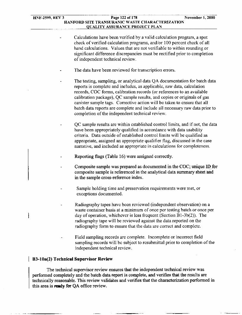
HNF-2599, REV 3 Page 122 of 178 November 1,2000 HANFORD SITE TRANSURANIC WASTE CHARACTERIZATION
QUALITY ASSURANCE PROJECT PLAN
- Calculations have been verified by a valid calculation program, a spot check of verified calculation programs, and/or 100 percent check of all hand calculations. Values that are not verifiable to within rounding or significant difference discrepancies must be rectified prior to completion of independent technical review.
The data have been reviewed for transcription errors. -
The testing, sampling, or analytical data QA documentation for batch data reports is complete and includes, as applicable, raw data, calculation records, COC forms, calibration records (or references to an available calibration package), QC sample results, and copies or originals of gas canister sample tags. Corrective action will be taken to ensure that all batch data reports are complete and include all necessary raw data prior to completion of the independent technical review.
- QC sample results are within established control limits, and if not, the data have been appropriately qualified in accordance with data usability criteria. Data outside of established control limits will be qualified as appropriate, assigned an appropriate qualifier flag, discussed in the case narrative, and included as appropriate in calculations for completeness.
- Reporting flags (Table 16) were assigned correctly.
Composite sample was prepared as documented in the COC. composite sample is referenced in the analytical data s u m in the sample cross-reference index.
- Sample holding time and preservation requirements were met, or exceptions documented.
- Radiography tapes have been reviewed (independent observation) on a waste container basis at a minimum of once per testing batch or once per day of operation, whichever is less frequent (Section B1-3b(2)). The radiography tape will be reviewed against the data reported on the radiography form to ensure that the data are correct and complete.
Field sampling records are complete. Incomplete or incorrect field sampling records will be subject to resubmittal prior to completion of the independent technical review.
I B3-10a(2) Technical Sttpervlsar Review
The technical supervisor review ensures that the independent technical review was performed completely and the batch data report is complete, and verifies that the results are technically reasonable. This review validates and verifies that the characterization performed in this area is ready fer QA office review.

HNF-2599, REV 3 Page 123 of 178 November 1,2000 HANFORD SITE TRANSURANIC WASTE CHARACTERIZATION
QUALITY ASSURANCE PROJECT PLAN
0 One hundred percent of the batch data reports must receive technical supervisory signature release for each testing batch, sampling batch, and analytical batch. The technical supervisory signature release must occur as soon as practical after the independent technical review to determine and correct negative quality trends in the sampling or analytical process. However, at a minimum, the technical supervisory signature release must be performed before any waste associated with the data reviewed is shipped to WIPP. This release must ensure the following as applicable:
The data are technically reasonable based on the technique used.
- All data have received independent technical review with the exception of radiography tapes, which will receive periodic technical review as specified in Section B1-3b(2).
- The testing, sampling, or amlytical data QA documentation data (as applicable),
ords, QC sample results, and original
- Sample holding time and preservation requirements were met, or
Field sampling records are complete.
exceptions documented.
-
Composite samples were prepared and reported in accordance with laboratory procedures.
I
I B3-10a(3) QA Officer Review
The data generation level QA review ensures that batch data report is complete, that QC checks and the appropriate QAOs have been met. This review verifies and validates that the characterization results meet and QAOs for the subject charac
QNQC, instrument performance criteria has been met, on area have been met.
a One hundred percent of the batch data reports will receive FQAO signature release. The FQAO signature release must occur as soon as practical after the technical supervisory signature release to determine and correct negative quality trends in the sampling or analytical process. However, at a minimum, the FQAO signature release must be performed before any waste associated with the data reviewed is shipped to WIPP. This release must ensure the following as applicable:
- Independent technical and technical supervisory reviews have been performed as evidenced by the appropriate signature releases.

HNF-2599, REV 3 Page 124 of 178 November 1,2000 HANFORD SITE TRANSURANIC WASTE CHARACTEFUZATION
QUALITY ASSURANCE PROJECT PLAN
- QA documentation and batch data report are complete as appropriate for
Sampling and analytical QC checks have been properly performed. QC
the point of hata generation
- criteria that were not met are documented.
- QAOs have been met according to the methods outlined in Section B3-1.
If data package errors or omissions are identified, the FQAO evaluates the nature of the problem and ensures the data package is revised as necessary. If the FQAO cannot rectify the problem by correcting the data package, an NCR or CAR is generated as described in Section B3-13. The FQAO ensures the information is available in the data package so the next level data review may be completed. After data packages undergo data generation-level review, validation, and verification, they are forwarded to the SQAO along with the required signature releases and checklists.
B3-10b Project Level
Data validation and verification at this level involves scrutiny and signaturc release from the SPM (or designee) and the SQAO (or designee). The pemiittees shall require the Hanford site to meet the following minimum requirements for each waste container. Any nonconformaiicc idcntiticd during this process shall be documented on an NCR (Section R3-13 of the WIPP-WAP).
The SPM and SQAO shall ensure that validation, and verification is performed on waste container quarterly (every three months) generation level review, validation, and verification are being performed according to procedures.
I B3-10b(l) Site Quality Assurance Officer
The SQAO review ensures that the batch data report received from the data generation is complete, validates and verifies that the QA checks were done properly and meet program criteria, and ensures that the QAOs have been met.
Data validation and verification at the project level involves scrutiny by and signature release from the SPM and SQAO to ensure that minimum requirements are met for each waste container. If the SPM or SQAO identify data package errors or omissions, they evaluate the nature of the problem and initiate revision of the data package, as necessary. If the SPM or SQAO cannot rectify the problem by correcting the data package, they initiate an NCR as described in Section B3-13. WMH-400, Section 7.1.6, “TRU Waste Project Level Data Validation and Verification” (see Table A-I), describes the project-level data validation, verification, and reporting process.
1 One hundred percent of the batch data reports must receive SQAO signature release. The SQAO signatwe release must occur a
k ” completion of the data g e n w t b n review, validatio as practical after -tm4etem&e .’., ,

HNF-2599, REV 3 Page 125 of 178 November 1,2000 HANFORD SITE TRANSURANIC WASTE CHARACTERIZATION
- QUALITY ASSURANCE PROJECT PLAN
and correct negative quality trends in the sampling or analytical process. However, at a minimum, the SQAO signature release must be performed before any waste associated with the data reviewed is shipped to WIPP. Ths signature release must ensure the following as applicable:
- Batch data reports are complete and data are properly reported (e.g., data
Sampling batch QC checks (e.g., equipment blanks, field duplicates, field
are reported in correct units and with correct qualifjmg flags).
- reference standards) were properly performed, and meet the established QAOs and are within established data usability cnteria
- Testing batch QC checks (e g , replicate scans, measurement system checks) were properly performed. Radiography data are complete and acceDtahle based on evidence of videotaoe review of one waste container per day or once per testing batch, whichever is less frequent, as specified in B1-3b(2).
Analytical batch QC checks (e.g., laboratory duplicates, laboratory blanks, matrix spikes, matrix spike duplicates, laboratory control samples) were properly performed and meet the established QAOs and are within established data usability criteria.
Proper procedures were followed to ensure representative samples of headspace gas and homogenous solids and soil/gravel were taken.
I B3-10b(2) Site Project Manager
The SPM review is the final validation that all of the data contained in batch data reports have been properly reviewed as evidenced by signature release and completed checklists.
One hundred percent of the batch data reports must have SPM signature release. The SPM signature release must occur as soon as practical after the SQAO signature release to determine and correct negative quality trends in the sampling or analytical process. However, at a minimum, the SPM signature release must be performed before any waste associated with the data reviewed is shipped to WIPP. This signature release must ensure the following:
Data generation level independent technical, technical supervisory, and QA oficer (or designee) review, validation, and verification have been performed as evidenced by completed review checklists and by the appropriate signature release.
- Batch data review checklists are complete.
- Verify that data are within established data assessment criteria and meet all applicable QAOs.

HNF-2599, REV 3 Page 126 of 178 November 1,2000 HANFORD SITE TRANSURANIC WASTE CHARACTERIZATION
QUALITY ASSURANCE PROJECT PLAN
I B3-f6b(3) Prepare SQAO Summary and Data Validation Summary
To document project-level data validation and verification, the SPM prepares a data for each batch data report, as validation summary and the SQAO prepares a SQAO s
described in WMH-400, Section 7.1.6. These reports m or incorporated into the SQAO and SPM checklists. The checklist for each batch data report in sufficient detail to validate all aspects of a hatch data report that affects data quality. The data validation summary provides confirmation that, on a per-waste-container basis, as evidenced by batch data report reviews, all data hav validated in accordance with the QAPjP. The data validation summary must idenbfy the batch data report reviewed, describe how the validation was performed, whether or not problems were detected, and include a statement indicating that all data are acceptable.
o eliminate redundancy summary includes a validation
In the case of analytical laboratory results, the laboratory will not dispose of samples I until notification is received from the SPM. The SPM will generally provide this notification
once the data has received project-level validation and verification. In some cases (e.g., lack of adequate numbers of canisters to continue sampling) the SPM may release the samples prior to the completion of the project level validation and verification. In those instances, if the data review determines that the data are inadequate, the drum will be resampled. Gas sample canisters may then be released from storage for cleaning, recertification, and subsequent reuse. Sample tags must be removed and retained in the project files before recycling the canisters. If the SPM requests that samples be retained for future use, the laboratory retains the samples under the same sample identification and COC and documents the reason for the sample retention.
I Sample tags are removed from released samples and forwarded to the project records custodian for filing as QA records.
1 B3-10b(4) Prepare Waste Stream Characterization Package
If the permittees request detailed information on waste stream characterization package. The SPM can re generation level technical supervisor, and QA officer to ass waste stream characterization package (Section B3-12b(2)) will support the SPM's waste characterization determinations.
, the site will provide a acterization area, data
ion and review of the to ensure the package
I B3-lOcPermittees' Level
The final level of data verification occurs at the permitte consist of an inventory check of the batch data reports to verify through the permittee's Audit and Surveillance Program (Permit
and must, at a minimum, mess. This is done
ent 36).
For initial WSPF approval, the permittees must verify that each submittal is complete and notify the originating site in writing of the approval of the WSPF. The permittees will maintain the data as appropriate for use in the regulatory compliance programs. At a minimum the verification must:
Ensure the correct assignment of the waste stream description, Waste Matrix Code Group, Summary Category Groups, and USEPA hazardous wmte codes
0 data

HNF-2599, REV 3 Page 127 of 178 November 1,2000 HANFORD SITE TRANSURANIC WASTE CHARACTERIZATION
QUALITY ASSURANCE PROJLCT PLAN
I 0
For subsequent shipments made after the WSPF approval, the verification will be made
Contain summarized results of characterization List the methods used for characterization.
via the WWIS internal limit
B3-11 Reconciliation with Data Quality Objectives
s (Section B-4b(l)(i)). I
The SPM assesses whether data of sufficient type, quality, and quantity were collected and whether the vanability of the data set is small enough to provide the required confidence in the results. The SPM also determines whether, based on the desired error rates and confidence levels, a sufficient number of valid data points were determined (as established by the associated completeness rate for each sampling and analytical process). In addition, the SPM documents that random sampling of waste containers was performed for the purposes of waste stream characterization. In association with the data validation and venfication described above, the SPM is responsible for ensuring that all data reported meet the DQOs in Section B-4.
1 B3-l la ReconciWion at the Project Level
The permittees shall require each SPM to ensure that all et the DQOs provided in Section B-4a(l) o Permit Attachment B.
st assess whether data of sufficient type, q collected. The SPM must determine if the variability of the data set the required confidence in the results. The SPM must also det error rates and confidence , a sufficient number of valid data (as established by the asso completeness rate for each s addition, the SPM must document that random sampling of containers was p purposes of waste stream characterization.
For each waste stream characterized, the SPM determines whether sufficient data were collected to determine:
I 0 Waste matrix code
0 Waste material parameter weights
0 Whether each waste container is TRU waste
0 Mean concentrations, UCL90 for the mean concentrations, standard deviations, and the number of samples collected for each VOC in the headspace gas of waste
I containers in the waste stream (if applicable)
0 Potential flammability of TRU waste headspace gases
Mean concentrations, UCL 90 for the mean concentrations, standard deviations, and number of samples collected for VOCs, SVOCs, and metals in the waste stream
0

~
HNF-2599, REV 3 Page 128 of 178 November 1,2000 HANFORD SITE TRANSURANIC WASTE CHARACTERIZATION
QUALITY ASSURANCE PROJECT PLAN
0
0
W I I
0
0
0
Whether the waste stream exhibits a toxicity characteristic (TC) under 40 CFR Part 26 1, Subpart C
Whether the waste stream can be classified as RCRA hazardous waste or nonhazardous waste at the 90 percent upper confidence level
Whether a sufficient number of waste containers were visually examined (as a QC check on radiography) to determine with a reasonable level of certainty that the UCLW for the miscertification rate is less than 14 percent (if applicable)
Whether all TICS were appropriately identified and reported in accordance with the requirements of Section B3-1 prior to submittal of a waste stream profile form for a waste stream or waste stream lot
Whether the overall completeness, comparability, and representativeness QAOs were met for each of the analytical and testing procedures as specified in Sections B3-2 through B3-9 prior to submittal of a waste stream profile form for a waste stream or waste stream lot
Whether the PRQLs for all analyses were met prior to submittal of a waste stream profile form for a waste stream or waste stream lot.
WMH-400, Section 7.1 .l , "TRU Waste Characterization Data Quality Objectives Reconciliation and Reporting" (see Table A-1) implements the DQO reconciliation process. If the SPM determines that insufficient data were collected to make the determinations listed above, additional data are collected. The reconciliation of a waste stream will be performed prior to submittal of the waste stream profile form for that waste stream. For subsequent shipments, data reconciliation is done on all containers or samples prior to shipment to WIPP.
The SPM evaluates and reports waste characterization data from the analysis of homogeneous solids, soiligravel, and debris waste streams following the statistical procedures presented in Section B2. These procedures, which include UCL90 calculations, are followed to assess compliance with the DQOs and are applied to all laboratory analytical data for headspace VOCs, total VOCs, total SVOCs, and total metals in samples of homogeneous solids and
I soil/gravel waste streams. The SPM verifies the assignment of USEPA hazardous waste numbers for the presence of spent solvents by comparing data from analysis of appropriate headspace VOCs, total VOCs, and total SVOCs to the PRQLs in Tables B3-1, B3-4 and B3-6,
I and 40 CFR Part 261, Subpart D. The SPM determines the assignment of TC USEPA hazardous waste numbers (40 CFR Part 261.24) by comparing AK information and data from the analysis of the appropriate metals and organic compounds to the regulatory threshold limit (RTL) values in 40 CFR Part 261, Subpart C and listed in Table B3-10. RTL values are obtained by calculating the weight/weight concentration (in the solid) of a TC analyte that would give the regulator weightivolume concentration (on the TCLP extract) assuming 100 percent analyte dissolution. WMH-400, Section 7.1.1, describes this data evaluation process.

HNF-2599, REV 3 Page 129 of 178 November 1,2000 HANFORD SITE TRANSURANIC WASTE CHARACTERIZATION
QUALITY ASSURANCE PROJECT PLAN
B3-12 Data Reporting Requirements
Data reporting requirements define the type of information and the method of transmittal for data transfer from the data generation level to the project level.
I B3-12a Data Generation Level
Facility personnel assign identification numbers to samples (e.g., gas samples, homogeneous solids samples, and soil/gravel samples), as described in Section B1-4. Facility personnel assign a unique identification number to every batch data report and every field and laboratory sample.
Facility personnel assign unique senal numbers to batch data reports and ensure that each page is numbered. The serial number used for data reports may be the same as the hatch number.
I Facility personnel transmit an electronic or hard copy of all batch data reports and data review checklists to the SPO. Facility procedures include report forms and checklists required by the applicable testing, sampling, and analytical methods. The batch data reports include the signature releases that document the data generation level review, validation, and verification as described in Section B3-10. Facility procedures listed in Table A-1 identify the procedures that implement data generation level data reporting requirements. The batch data reports are maintained in the project files in accordance with WMH-400, Section 1.5.1 (see Table A-I).
I B3-12b Project Level
The SPO must ensure that the characterization information summary and waste stream characterization package (when r y the permittees) are prepared as app addition, the SPO shall prepare a each waste stream certified for shipm The SQAO must also verify cons’ information found in batch reports. Summarized , and data are included with The contents of the WSPF, the characterization package are di
on information summary, and the waste stream following sections.
A waste stream charaaerization package must be submitted when requested by the permittees.
I
1 B3-12b(l) Waste Stream Profile Form and Waste Characterization Information Swmmary
The WSPF (Figure B-1) includes the following information:
Generator/storage Generator/storage
Assignment of was SummaryCat
rn Waste Matrix Code Group WasteBtceamname
Date of audit rt?port rrpproval by NMED (if obtained)
-USEPA kazardous waste codes, Washingtw

HNF-2599, REV 3 Page 130 of 178 November 1,2000 HANFORD SITE TRANSURANIC WASTE CHARACTERIZATION
QUALITY ASSURANCE PROJECT PLAN
I Applicable TRUCON codes Certification signature of SPM, name, title, and date signed will be included.
The characterization information summary includes the following elements: I I Data reconciliation with DQOs
I Cross-reference of container identification numbers to each batch data report
Headspace-gas summary data listing the identification numbers of samples used in the statistical reduction, the maximum, mean, standard deviation, UCL90 , RTL, and associated USEPA hazardous waste codes that must be applied to the waste stream
I I
TIC listing and evaluation, and verification that AK was confirmed
RTR and VE summary to document prohibited items are not present and to confirm AK
AK summary including waste stream name, waste stream number, point of generation, waste stream volume, generation TRUCON codes, TWBIR information, generating processes, RCRA de ations, and radionuclide information.
After approval of a WSPF and the as ch information summary by the permittees, the generatorktorage site are to oss-reference of container identification numbers to each batch data report.
I B3-12b(2) Waste Stream Characterization Package
I The waste stream characterization package consists of the following:
WSPF Accompanying characterization information summary Complete AK summary Batch data reports supporting the confirmation of AK as well as others requested by the permittees.
I B3-12b(3) WIPP Waste Information System (WWrS) Data Reporting
The SPM reports data on an individual waste container basis to CAO using the WIPP WWIS, as specified in the WIPP-WAP, and on a waste stream basis using a WSPF. For each waste stream or lot, the SPM will submit the WSPF and the reconciliation with DQOs report to the CAO and the WIPP management and operating contractor. WMH-400, Section 7.1.5, contains specific requirements for transmitting information via WWIS. If a container was part of a composite headspace-gas sample, the analytical results &om the composite sample mlrd be assigned as the container headspace gas data results, including associated TICS.

HNF-2599, REV 3 Page 131 of 178 November 1,2000 HANFORD SITE TRANSlJRANIC WASTE CHARACTERIZATION
QUALITY ASSURANCE PROJECT PLAN
B3-13 Nonconformances
The SPM and the SQAO will monitor and control the waste characterization activities at the site. This monitoring and control will include nonconformance identification, documentation, and reporting. The nonconformances and corrective action process shall comply
1 with the nonconformance requirements specified in Section B3-I ofthe QAPjP.
The nonconformance and corrective action processes are specified below.
Nonconformances
A nonconformance is a deficiency in a TRU Project requirement that renders the quality of an item or sample as unacceptable or indeterminate. Nonconformances include uncontrolled and unapproved deviations from an approved plan or procedure. Nonconforming items and activities are those that do not meet TRU Project requirements. Controlled changes to TRU Project plans or procedures that affect WAP requirements by either creating a condition that is not in compliance with the requirements or is the result of a corrective action plan for a documented condition adverse to quality will be addressed as part of the nonconformance and corrective action process.
All TRU Project participants are responsible for quality improvement, including identifying and reporting nonconforming items and processes adverse to quality with a no fault attitude fostered by management. Nonconforming items are marked and segregated as necessary to prevent their inadvertent use and are dispositioned appropriately. The SQAO and facility managers are responsible for evaluating nonconformances and taking appropriate corrective action. WMH-400, Sections 1.3.2 and 1.3.3, identify the process used to control nonconforming items and processes. These procedures identify the person(s) responsible for evaluating, dispositioning, and controlling nonconformances and segregating or otherwise tracking nonconforming items. The individual identifying the nonconformance initiates an NCR or CAR. NCRs are normally developed for nonconforming items and CARs are developed to correct a deficient process. Facility personnel report project-related nonconformances and transmit copies of NCRs and CARs to the SQAO.
Each NCR or CAR includes the following information:
e
0 Description of the nonconformance 0 Method(s) of corrective action 0
0
0
Identification of individual(s) identifying or originating the NCR or CAR
Schedule for completing the corrective action Cause of nonconformance (if known) and action to prevent recurrence A copy of, or reference to, appropriate background information (e.g., analytical results, QC tests, audit report, internal memoranda, letters) Indication of the potential ramifications and overall usability of the data, if applicable Approval signatures of facility personnel.
0
0

HNF-2599, REV 3 Page 132 of 178 November 1,2000 HANFORD SITE 'TRANSURANIC WASTE CHARACTERIZATION
QUALITY ASSURANCE PROJECT PLAN
Nonconformances may be detected and identified by anyone performing characterization activities, including:
e Project staff - during field operations, supervision of subcontractors, data validation and verification, and self-assessment
Laboratory staff - during the preparation for and performance of laboratory testing; calibration of equipment; QC activities; laboratory data review, validation, and verification; and self-assessment
The SQAO oversees the nonconformance report process and is responsible for developing a plan to identify and track all nonconformances and report this information to CAO. Documentation of nonconformances will be made available to the SPM, who in turn is responsible for notifying project personnel of the nonconformance. Completion of the corrective action for nonconformances must be verified by the SQAO.
QA personnel - during oversight activities or audits.
The TRU Project will provide CAO written notification of all nonadministrative I nonconformances related to requirements of the QAF'jP (e.g. , a failure to meet a DQO) first
identified during the SPM review within 5 days of identification. They will also provide CAO a nonconformance report within 30 days of identification. A corrective action process will be
I implemented and the identified nonconformance will be resolved prior to the shipment of TRU waste.
B3-14 Special Training Requirements and Certifications
Training records are maintained in the SPO files, as described in Section B-4a. The SPM, facility, laboratory, and other support managers ensure that all TRU Project personnel receive indoctrination into the scope, purpose, and objectives of the program and the specific QAOs of the task being performed. TRU Site Project personnel receive initial and continuing training requisite with their activities and level of responsibility, and maintain minimum qualifications as described in WMH-400, Section 1.2.1. The TRU Project SPM will review qualifications and detennine on a case-by-case basis the application of equivalent experience, as . . . '
~ shown in Table B3-10 ofthe WIPP-WAP.:
Before beginning work, personnel qualifications will be evaluated for compliance with training and qualification requirements. Personnel who are found to be deficient with regard to the requirements for their assigned position will receive the appropriate training to ensure that the qualification requirements are met before participating in project-related activities. Facility personnel performing activities affecting quality are trained according to facility training plans to ensure that they achieve and maintain suitable proficiency. It may be necessary to complete initial qualification of specific project personnel prior to establishing a formal OJT program. These personnel will be evaluated by the training manager for qualification and will perform OJT of subsequent personnel. Table B3-11 specifies the minimum qualifications for radiography and analytical laboratory personnel. Facility procedures identify the facility-specific job titles that casqond to the positions listed in Table B3-11. Job performance is evaluated, where

HNF-2599, REV 3 Page 133 of 178 November 1,2000 HANFORD SITE TRANSURANIC WASTE CHARACTERIZATION
QUALITY ASSURANCE PROJECT PLAN
appropriate, and documented at penodic intervals not to exceed two years Personnel involved in characterization activities will receive continuing training to ensure that job proficiency is maintained. Training includes both education in pnnciples and enhancement of skills. Analytical laboratory line management must ensure that analytical personnel are qualified to perform the analytical method(s) for which they are responsible.
I B3-15 Changes to WAP-Related Plans or Procedures
Controlled changes to WAP-related plans or procedures shall be managed through the document control process described in the QAPD. The SPM and the SQAO shall review all non- administrative changes and evaluate whether those changes could impact DQOs specified in the permit. After site certification, any changes to WAF'-related plans or procedures that could positively or negatively impact DQOs (e.g., those changes that require p approval of the permittees as defined in Section B5-2) shall be reported to the permittees within five days of identification by the project level review. The permittees shall send NMED a monthly summary briefly describing the changes to plans and procedures identified pursuant to section during the previous month.

HNF-2599, REV 3 Page 134 of 178 November 1,2000 HANFORD SITE TRANSURANIC WASTE CHARACTERIZATION
QUALITY ASSURANCE PROJECT PLAN
TABLE B3-1 WASTE MATERIAL PARAMETERS AND DESCRIPTIONS
Waste Material Parameter
Iron-based Metals/Alloys
Aluminum-based Metals/Alloys
Other Metals
Other Inorganic Materials
Cellulosics
Rubber
Plastics (waste materials)
Organic Matrix
Inorganic Matrix
Soildgravel
Steel (packaging materials)
Plastics (packaging materials)
Description
Iron and steel alloys in the waste; does not include the waste container materials
Aluminum or aluminum-based alloys in the waste materials
All other metals found in the waste materials
Nonmetallic inorganic waste including concrete, glass, firebrick, ceramics, sand, and inorganic sorbents
Materials generally derived from high-polymer plant carbohydrates; (e.g., paper, cardboard, wood, and cloth)
Natural or man-made elastic latex materials; (e.g., surgeons' gloves, and leaded rubber gloves)
Generally man-made materials, often derived from petroleum feedstock (e.g., polyethylene and polyvinylchloride)
Cemented organic resins, solidified organic liquids and sludges
Any homogeneous materials consisting of sludge or aqueous- based liquids that are solidified with cement, calcium silicate, or other solidification agents; (e.g., wastewater treatment sludge, cemented aqueous liquids, and inorganic particulates)
Generally consists of naturally occumng soils that have been contaminated with inorganic waste materials
55-gal (208-L) drums
90-mil oolvethvlene drum liner and olastic bags
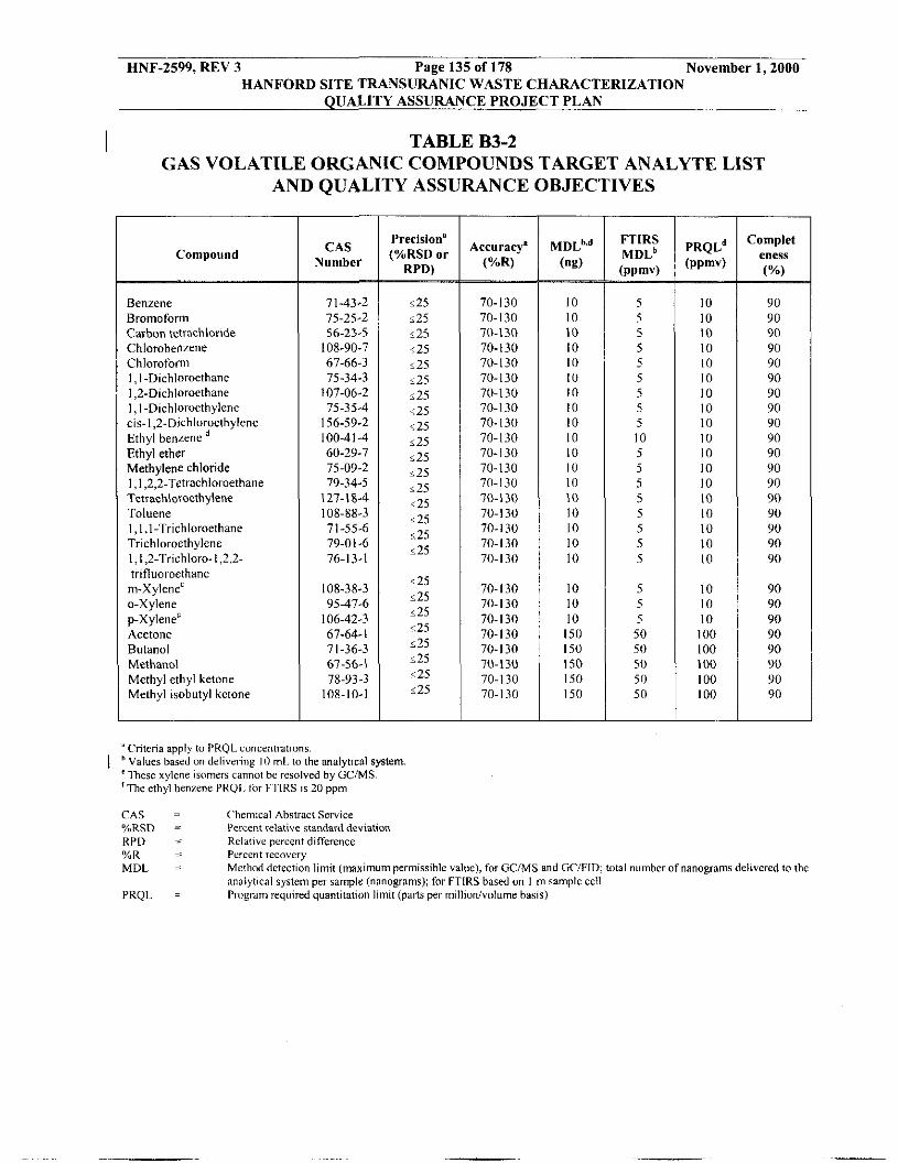
HNF-2599, REV 3 Page 135 of 178 November 1,2000 HANFORD SITE TRANSURANIC WASTE CHARACTERIZATION
QUALITY ASSURANCE PROJECT PLAN
TABLE B3-2 GAS VOLATILE ORGANIC COMPOUNDS TARGET ANALYTE LIST
AND QUALITY ASSURANCE OBJECTIVES
I
Compound
- - Benzene Bromoform Carbon tetrachlonde Chlorobe~venc Chlorofom 1 , I-Dlchloroethanc I ,2-Dichloroethane 1 , I-Dichloroethylene CIS- 1,2-D1chloroethylene Ethyl benrcne Ethyl ether Methylene chlonde I , I ,2,2-Tctrachloroethane Tetrachloroethylene Toluene 1 , I ,I-Trichloroethane Trichloroethylene l,1,2-Trichloro-l,2,2- trifluoroethane
m-Xylene' o-Xylene p-xylene' Acetone Butanol Methanol Methyl ethyl ketone Methyl isobutyl kctone
CAS Number
71-43-2 75-25-2 56-23-5 108-90-7 67-66-3 75-34.3 107-06-2 75-35-4 156-59-2 100-41 -4 60-29-7 75-09-2 79-34-5 127-1 8-4
71-55-6 79-01-6 76-13-1
108-88-3
108-38-3 9547-6 106-42-3 67-64-1 71-36-3 67-56-1 78-93-3
loa-10-1
Precision' (YoRSD or
RPD)
125 1 25 125 .25 125 125 i25 <25 <25 i25 125 i25 s25 125 125 ~ 2 5 125
125 125 i25 <25 i25 i25 <25 i25
9ccuracy' (%R)
70-130 70-130 70-130 70-130 70-130 70-130 70-130 70-130 70-130 70-130 70- I 30 70-130 70-130 70-130 70-130 70-130 70-130 70-130
70-130 70-130 70-130 70-130 70.130 70-130 70-130 70-130
M D L ~ . ~ (ng)
~
10 10 10 10 10 10 10 I O 10 10 10 10 I O 10 I O 10 I O I O
I O I O I O
150 I50 I50 150 150
FTlRS M D L ~
(ppmv) ~
5 5 5 5 5 5 5 5 5 10 5 5 5 5 5 5 5 5
5 5 5
50 50 50 50 50
~
P R Q L ~ (ppmv) -
I O I O 10 10 10 10 10 10 10 10 10 10 10 10 10 I O 10 10
10 I O I O
100 100 100 100 100
~
C o m p I e t eness (%)
~
90 90 90 90 90 90 90 90 90 90 90 90 90 90 90 90 90 90
90 90 90 90 90 90 90 90
"Criteria apply to PRQLconcentrations.
"These xylene isomers cannot be resolved by GCIMS ' T h e ethyl henzene PROI. Ibr FTlRS IS 20 ppm
CAS ('hemzcal Abstract Service %RSD = Percent relative standard deviation RPD = Rclativr percent difference
I Values based on delivel-inE I O ml. to the analytical system.
Y" R - - Percent recovery MDL = Methcd detection limit (maximum permissible value), for GCIMS and GCIFID; total number ofnanamams delivered to the
analytical system per sa&pIc (nanograms); for FTlRS based on I m sample fell .
PRQL = Program required quantitation limit (parts per millionIvolume hasis)

HNF-2599, REV 3 Page 136 of 178 November 1,2000
QUALITY ASSURANCE PROJECT PLAN
TABLE B3-3
HANFORD SITE ' r m s u w i c WASTE CHARACTERIZATION
SUMMARY OF LABORATORY QUALITY CONTROL SAMPLES AND FREQUENCIES FOR HEADSPACE GAS VOLATILE ORGANIC COMPOUND
ANALYSIS
Procedure
BFB Tune Evaluation
5-pt Initial Calibration (5 standards) Initial Calibration Verification (ICV) Continuing Calibration Verification (CCV)
QC Sample
Method performance samples
Frequency of Acceptance Criteria Procedure
Prior to starting any analysis and every I2 hours Initially, and as needed
Immediately following 70.130 % R Initial 5-pt Calibration
Every 12 hours, after BFB, prior to laboratory blank and everv 12 hours
Abundance critcria for all key ions are met in Table B - 16
%RSD of response f x t o r for each analyte <35
% D for all compounds 530 of initial calibration
Laboratory duplicates or on- line duolicates
Laboratory Blank
Internal Standard
Laboratory blanks or on-line blanks
of analysis Every 12 hours, after BFB and CCV, and I2 hours of analysis Add to every calibration standard. blank. and
Analyte amounts s 3 x MDLs from Table 83-2
Standard's area shall be within 50400% of CCV
Laboratory control samples (LCS) or on-line control samples
GCIMS comparison sample (for FTIRS only)
Blind audit samples
Minimum Frequency
Seven (7) samples initially and minimum four (4) semiannually
One ( I ) per analytical or on-line batch
Daily prior to sample analysis for GC/MS and GCIFID. Otherwise daily prior to sample analysis and one ( I ) per analytical batch or on- line batch for FTIRS.
One set (LCSILCSD) per analytical or on-line batch. Control charting of one LCS per batch can he used instead of the LCSILCSD set if sufficient historical data is available. One (I) per analytical or on-line hatch
Samples and frequency controlled bv the Headsoace Gas PDP Plan
Acceptance Criteria
Meet method QAOs; 70- I30%R for concentrations > lowest initial calibration standard RPD i 25 for detections in both samples > PRQL
Analyte amounts < 3 x MDLs from Table 83-2 for GCiMS and GCIFID, < PRQL for FTlRS
70-1 30 %R RPD 5 25 for LCSiLCSD
RPD i 25 for detections in both samples > PRQL
Specified in the Headsoace Gas PDP Plan
Nonconformance if RPD >25 for detections in both samples
> 3 x MDLs from Table B3-2 for G U M S and GCIFID; > PRQL for FTlRS
or>130 or if RDP>25 for
for detections in both samples
Gas PDP Plan
GUMS TUNES, INITIAL CALIBRATION AND CONTINUING CALIBRATIONS
Technique
W M S
I sample I standard's area

HNF-2599, REV 3 Page 137 of 178 November 1,2000 HANFORD SITE TRANSURANIC WASTE CHARACTERIZATION
QUALITY ASSURANCE PROJECT PLAN
GUMS TUNES, INITIAL CALIBRATION AND CONTINUING CALIBRATIONS
Technique
GCIFID
Procedure I Frequency of
Continuing calibration Every 12 hours
%RSD ofresponse fdctor for each analyte <30
Linear regression plots yield straight line an %R is 70-130 for each standard analyte
initial calibration. RTs i 3 standard deviations of.initial
Corrective action per Section 83-13 when final reported QC samples do not meet the acceptance criteria Applies only to concentrations greater than the PRQLs listed in Table B3-I
MDL =~ Method Detection Limit QAO 3 Quality Assurance Objective PDP =~ Performance Demonstration Program PRQL Program Required Quantitation Limit %R = Percent Recovery RPD = Relative Percent Difference

HNF-2599, REV 3 Page 138 of 178 November 1,2000 HANFORD SITE TRANSURANIC WASTE CHARACTERIZATION
QUALITY ASSURANCE PROJECT PLAN
TABLE B3-4 VOLATILE ORGANIC COMPOUNDS TARGET ANALYTE LIST
I AND QUALITY ASSURANCE OBJECTIVES ~ -
Compound
Benzene Bromoform Carbon Disulfide Carbon Tetrachloride Chlorobenzene Chloroform I ,4-Dichlorobenzenec ortho-Dichlorobenzene' I ,2-Dichloroethanc I .I -Dichlorocthylcnc Ethyl benrene Methylene chlonde I .I ,2,2-Tctrachluroelhane Tetrachloroethylene Toluene 1 , I ,I -Trichlorocthane 1 ,I ,2-Trichloroethane Trichloroethylene T~nchlorofluoromethane I .I .2-Trichloro-l,2,2-trifluoraethane Vinyl Chloride m-xylene 0-xylene p-xylene Acetone Butanol Ethyl ether Isabutand Methanol Methyl ethyl ketone Pyridine'
~
CAS Number 7143-2 75-25-2 75-15-0 56-23-5 108-90-7 67-66-3 106-46-7 95-50-1 107-06-2 75-354 100-41 4 75-09-2 79-34-5 127.184 108-88-3 71-55-6 79-00-5 79-01-6 75-69-4 76-13-1 75-014 108-38-3 95-47-6 106-42-3 67-64-1 7 1-36-3 60-29-7 78-83-1 67-56-1 78-93-3 110-86-1
~
- Precision'
('%RSD or RPD) 1-45 147 c50 130 138 144 160 160 542
1250 143 150 15' 12il S29 $33
550 2-200 150 150 150 1-51) 150 S50 150 150 350 150
~
~
Accuracy' ( 'XR) 37-151 45-16') 60-150 70-140 37-160 51-138 18.190 18-190 49.155
37-162
46.157 64-148 47-150 52.162 52.150 71-157 17-181 60-150 D-251' 60-150 60-150 60.150 60-150 60-150 60-150 60-150 60-150 60-1 50
D-234'
0.221~
60-1 50
~
M D L ~ L!SLkL
I I I I I I I I I I I I I I I I I I I I I I 1 I
IO' I O " I Or I O ? I O ? I O " I Or
L
PRQL' A!Z&L
I O I O 10 I O I O I O 10 I O I O I O I O 10 I O I O I O I O I O I O I O I O 4 I O I O I O
IO0
I00 I00 I00 IO0 IO0
I on
- Completeness
(%) 90 90 90
90 90 90 YO 'J0 90 90 90 90 90 90
90 90 90 90 90 90 90 90 90 90 90 90 90 90 90
90
90
- Criteria apply to PRQL concentrations TCLP MDL and PRQL values are reported in uniu of mgll and l i n m are reduced by a factor of 20
Detected; result must be greater than zero. Estimate. to be determined.
I Can also be analyzed as a semi-volatile organic compound, If analyxed as a swn-volatile compound. the QAOs of Table 83.6 apply.
CAS = Chemical Abstract Service '%RSD = Percent relative standard deviation RPD = Relative percent difference "AIR ~
MDI. = Methud detection limit (maximum permissible value) (milligrams per kilogram) PRQI. = Program required quantitation limit, calculated from the toxicity characteristic level for benzene assummg a 0.9 OL
(25-gram [g]) sample, 0.1 gal (0.5 liter [LI) of extraction fluid. and 100 percent analyte extraction (milligrams per kilogram)
NOTE ~ There mny be o l k r compounds rlmt ne-ed 10 be nnnly;ed,for 1mn.yonnrion
Percent recovery -

HNF-2599, REV 3 Page 139 of 178 N o v e m b e r 1,2000 HANFORD SITE TRANSURANIC WASTE CHARACTERIZATION
QUALITY ASSURANCE PROJECT PLAN
TABLE B3-5
SUMMARY OF LABORATORY QUALITY CONTROL SAMPLES AND FREQUENCIES FOR VOLATILE ORGANIC COMPOUND ANALYSIS
QC Sample
Method performance Emples Laboratory duplicatesb __ Laboratory blanks ~
Matrix spikesb
Matrix spike duplicates
Laboratory control samples
GClMS Calibration
GC/MS Calibration (continued)
Minimum Frequency
Seven (7) samples initially and four (4) semiannually
One ( I ) per analytical batch
One ( I ) per analytical batch
One ( I ) per analytical batch
One ( I ) per analytical batch
One ( I ) per analytical batch
BFB Tune every 12 hours
5-pt. Initial Calibration initially, and as needed
Continuing Calibration every I2 hours
Acceptance Criteria
Meet Table 83 -4 QAVs
Meet Table 83-4 precision 2AOs
hnalyte concentrations I 3 < MDLs
Meet Table 83 -4 accuracy 2AOs
Meet Table 83-4 accuracy ind precision QAOs
30-120%R
4bundancc criteria met as per method
Calibrate according to SW- 846 Method requirements:
%RSD for CCC I 30, %RSD for all other :ompounds i 15%
Average response factor (RRF) used if%RSD s 15, use linear regression if %RSD>I5; R o r R 2 > 0.990 if using alternative curve
System Performance Check Compound (SPCC) minimum RRF as per SW- 846 Method, RRF for all other compounds L 0.01
"AD I 20 for CCC;
SPCC minimum RRF as per SW-846 Method; RRF for all other cornpounds L 0.01
RT for internal standard must be I 30 seconds from last daily calibration, internal standard area count must bc >50% and <ZOO% of last daily calibration
Corrective Action
iepeat until acceptable
Vonconformance if RPDs > d u e s in Table 83-4
Vonconformance i f analyte :oncentrations > 3 x MDLs
Vonconformance if %Rs ire outside the range ,pecified in Table B3-4
VonconfOrmance I f RF'Ds ialues and %Rs outside mge specifled in Table 83-4
Vonconformance i f%R < 30 or > 120
Repeat until acceptable
Repeat until acceptable

November 1,2000 HNF-2599, REV 3 Page 140 of 178 HANFORD SITE TRANSURANIC WASTE CHARACTERIZATION
QUALITY ASSURANCE PROJECT PLAN
Surrogate compounds r Blind audit samples
'Corrective Action per sectio
Minimum Frequency
3-pt. Initial Calibration initially and as needed
Continuing Calibration every 12 hours
Each analytical sample
Samples and frequency controlled by the Solid PDP Plan
Acceptance Criteria
Correlation Coefficient L
0.990 or %RSD s 20 for all analytes
%D or %DriR for all analytes i I5 of expected values,
RT i 3 standard deviations from initial calibration
Average %R from minimum of 30 samples for a givcn matrix 23 standard deviations
Specified in the Solid PDP Plan
Corrective Action'
Repeat until acceptable
Nonconformance if %R < (average %R - 3 standard deviation) or > (average %R + 3 standard deviation)
Specified in the Solid PDP Plan
13-13 when final reported QC samples do not meet the acceptance criteria. Nonconformances do not apply to matrix related exceedances.
in Table 83-4.
MDL - QAO PDP Yo R - RPD -
May be satisfied using matrix spike duplicate; acceptance criteria applies only to concentrations greater than the PRQLs listed
Method detection limit Quality assurance objective Performance Demonstration Program Percent recovery Relative percent difference
- - ~
~ ~
~
-

HNF-2599, REV 3 Page 141 of 178 November 1,2000 HANFORD SITE TRANSURANIC WASTE CHARACTERIZATION
QUALITY ASSURANCE PROJECT PLAN
TABLE B3-6 SEMI-VOLATILE ORGANIC COMPOUND TARGET ANALYTE LIST
I AND QUALITY ASSURANCE OBJECTIVES
CAS = Chemical Abstract Service "ARSD = Percent relative standard deviation KPD = Reiative percent difference "AK Percent recuvery MIX. = PRQL =
- ~
Method detcction limit (maximum permissible value) (milligrams per kilogram) Program required quantilation limit: calculated from the toxicity characteristic level for nitrobenzene assuming a 100-gram (gj sample. 0.5 gal (2 liter [I.]) of extraction fluid, and 100 percent analyte extraclion (mtllig~ams per kilograms)
"Criteria apply to PRQI. ~unc~nlrst iuns
' Can also be anslyzed as a volatile organic compound
' Detected: result must be greater than zero
TCLP MDL and PRQL value^ are I-eported in units of mg/l and limits are reduced by a factor of20
Required only (or waste matrix code Si220 (organic sludges)

HNF-2599, REV 3 Page 142 of 178 November 1,2000 HANFORD SITE TRANSURANIC WASTE CHARACTERIZATION
QUALITY ASSURANCE PROJECT PLAN
I TABLE B3-7 SUMMARY OF LABORATORY QUALITY CONTROL SAMPLES AND
FREQUENCIES FOR SEMI-VOLATILE ORGANIC COMPOUNDS ANALYSIS
OC Samnle nethod performance samples
.aboratory duplicatesb
.aboratory blanks
Aatrix spikes
W M S Calibration
X i E C D Calibration
Minimum Frequency Seven (7) samples initially ind four (4) semiannuallv
3nc ( I ) per analytical batch
3ne ( I ) per analytical batch
3ne ( I ) per analytical batch
DFTPP Tune every 12 hours
5-pt Initial Calibration snitially, and as needed
Continuing Calibration every 12 hours
5-pt. Initial Calibration initially and as needed
Continuing Calibration every I2 hours
Acceptance Criteria Meet Table 83-6 QAOs
Meet Table 83-6 precision QAOs
Analyte concentrations i 3 x MDLs
Meet Table 83-6 accuracy QAOs
Abundance criteria met as per method
Calibrate according to SW- 846 Method requirements:
%RSD for CCC < 30, %RSD for all other compounds i 1 5 % Average response factor (RRF)used i f%RSD i 15, use linear regression i f>15; R or R2 20.990 if using alternative curve
System Performance Check Compound (SPCC) minimum RRF as per SW-846 Method; RRF for a11 othcr compounds L 0.01
% D i 20 for CCC,
SPCC minimum RRF as per SW-846 Method; RRF for all other compounds > 0.01
RT for internal standard must be t 30 seconds from last daily calibration, internal standard area count must be >50% and <ZOO% of last daily calibration
Correlation Coefficient i 0.990 or %RSD < 20 for a11 a"alyteS
%D or %DriR for all analytes 5 15 of expected values,
RT i 3 standard deviations of initial calibration
Corrective Action. kpeat until acceptable
donconformance If RPDs > alues In Table B3-6
ionconformance If analyte oncentrations > 3 x MDLs
donconformance i f RPDs !slues and %Rs are outside ange specified in Table 83-6 lcpeat until acceptable
kpea t until acceptable

HNF-2599, REV 3 Page 143 of 178 November 1.2000 HANFORD SITE TRANSURANIC WASTE CHARACTERIZATION
QUALITY ASSURANCE PROJECT PLAN
TABLE B3-7 (cont.) SUMMARY OF LABORATORY QUALITY CONTROL SAMPLES AND
FREQUENCIES FOR SEMI-VOLATILE ORGANIC COMPOUNDS ANALYSIS
Q C Sample Minimum Frequency Matrix spike duplicates One ( I ) per analytical batch
Laboratory control samples
Surrogate compounds Each analytical sample
One ( I ) per analytical batch
Acceptance Criteria Meet Table B3-h accuracy and precision QAOs
80 - 120 %R
Average %R from minimum of 30 samples from a given matrix + 3 standard deviations
~
Blind audit samples
Corrective Actionn Nonconformance if RPDs and %R > values in Table B3-6
Nonconformance i f%R < 80 o r > 120
Nonconformance i f%R <(average %R - 3 standard deviations) or > (average %R + 3 standard deviations)
Specified in the Solid PDP Plan
Samples and frequency controlled by the Solid PDP Plan
Specified in the Solid PDP Plan
' Corrective action per Section 83-1 3 when final reported Q C samples do not meet the acceptance criteria. Nonconformances do not apply to matrix related exceedances.
listed in Table B3-6.
MDL = Method Detection Limit QAO = Quality Assurance Objective PDP = Performance Demonstration Program %R = Percent Recovery RPD = Relative Percent Difference
May be satisfied by using matrix spikc duplicate; acceptance criteria applies only to concentrations greater than the PRQLs

HNF-2599, REV 3 Page 144 of 178 November 1,2000 HANFORD SITE TRANSURANIC WASTE CHARACTERIZATION
QUALITY ASSURANCE PROJECT PLAN
TABLE B3-8 METALS TARGET ANALYTE LIST
AND QUALITY ASSURANCE OBJECTIVES
Antimony
Precision (%RSD or Accuracy
(%R)b CAS
Number Analyte RPD)”
7440-36-0 130 I 80-120 100
Vanadium I 7440-62-2 I ~ 3 0 I 80-120 Zinc 1 7440-66-6 I ~ 3 0 1 80-120
100
2000 100 20 100 100 4.0 100 20 100 100 100 100
100 I 100 2000 100 20 100 100 4.0 100 20
100 100 100 100
Completeness (”/.I
90 90
90 90 90
90 90 90 90 90
90 90 9n
90
‘ I 30 percent control limits apply when sample and duplicate concentrations are > I O x IDl. for ICP-AFS and AA techniques, and i 100 x ID1 for Inductively Coupled PlasmaOMass Spectrometry (ICI’-MS) techniques. If less than these limits, the absolute difference between the t~vu values shall be less than OT equal to the PRQL.
tati is tical control limits IS used. then the established control limits tor that material shuuld be used for accuracy requirements. “ICLP PRQL values are reported ~n units of mgil and limits are reduced by a factor of 20. ‘ PRDL set such that i t is a factor of 10 below the PKQl. for 100 percent solid samples, assuming a l0Ox dilution dr rhg digestion.
CAS ~ Chemical Abstract Sewice %nSD - Percent relative standard deviation
Relative percent difference RPD ~
%R - Percent recovery
Applies to laboratory f ~ n t r d samples, and labaratoly matrix spikes. If P solid laboratory control sample material which has established
- - - -
I PRDL - - Program required detection limit (Le., maximum permissible value for IIX.) (micrograms per liter)
- I pRQL ~ Program required quantitation limit (milligrams per kilogram)

HNF-2599, REV 3 Page 145 of 178 November 1,2000 HANFORD SITE TRANSURANIC WASTE CHARACTEIUZATION
QUALITY ASSURANCE PROJECT PLAN
TABLE B3-9 SUMMARY OF LABORATORY QUALITY CONTROL SAMPLES AND
i JCQUENCIES FOI Minimum Freauencv
METALS ANALYS ACCeDtanCe Criteria OC S a m l e Corrective Action.
Repeat until acceptable Meet Table B3-8 QAOs Method performance samples
Seven (7) samples initially and four (4) iemiannuall y
3ne ( 1 ) per analytical batch
Laboratory blanks i 3 x IDL ( s 5 x IDL for 1CP-MS)'
Redigest and reanalyze any samples with analyte concentrations which are s 10 x blank value and t 0.5 x PRQL
Matrix spikes One (1) per analytical batch
Meet Table 83-8 accuracy QAOs
Nonconformance if %R outside the range specified in Table B3-8
Matrix spike duplicates One (1) per analytical batch
Meet Table B3-8 accuracy and precision QAOs
Nonconfornmnce if RPDs values and %R> outside the range specified in Table B3-8
ICP-MS Tune (ICP-MS Only)
Daily Nonconformance if %RSD > 5 ; mass calibration > 0.9 amu; resolution > 1 .O amu
4 Replicate %RSD i 5 ; mass calibration within 0.9 amu; resolution < 1.0 amu full width at 10% peak height
90-1 I O %R (80-120% for CVAA, GFAA, HAA, FLAA) for initial calibration verification solution. Regression coefficient t 0.995 for FLAA, CVA, GFAA, MAA
90-1 10% for continuing calibration verification solution. (80.120% for CVAA, GFAA, HAA, FLAA)
Meet SW-846 Method 6020 criteria
Daily Correct problem and recalibrate; repeat initial calibration
Initial Calibration 1 blank, 1 standard (ICP, ICP-MS) 3 standard, 1 blank (GFAA, FLAA) 5 standard, 1 blank (CVAA, HAA)
Continuing Calibration Every 10 samples and beginning and end of run
Correct problem and recalibrate; r e m last I O samples
Internal Standard Area Verification (ICP-MS)
Every Sample Nonconformance if not reanalyzed at 5 X dilution until criteria are met
Serial Dilution (ICP. ICP- MS)
One (1) per analytical batch
5 X dilution must he s 10% D of initial value for sample > 5OxIDL
Flag data if >lo% and > 5OxIDL

HNF-2599, REV 3 Page 146 of 178 November 1,2000 HANFORD SITE TRANSURANIC WASTE CHARACTERIZATION
QUALITY ASSURANCE PROJECT PLAN
TABLE B3-9 (eont.) SUMMARY OF LABORATORY QUALITY CONTROL SAMPLES AND
FREQUENCIES FOR METALS ANALYSIS
I
Interference Correction Verification (ICP, ICP-
Laboratory Control Samples
Blind audit samples
I
Minimum Frequency
Beginning and end of run or every 12 hours (8 for ICP) whichever is more frequent
One ( 1) per analytical batch
Samples and frequency controlled by the Solid PDP Plan
Acceptance Criteria
80.120% recovery for analytes
Note: Acceptance Criteria and Corrective Action apply only if interferents found in samples at levels greater than ICs A Solution
Table B3-8 accuracy QAOs
Specified in the Solid PDP Plan
Corrective Action'
Correct problem and recalibrate, nonconformance if not corrected
Redigest and reanalyze for affected analytes; non conformance if not reanalyzed
Specified in the Solid PDP Plan
' C'omrclivr action per Section 83-13 when final reporled QC samples do not meet the acceptance criteria. Nonconfumances do not apply to matrix related enceedances. 'Applies only to con~entratmns greater than the PRQLr listed in Table B3-8. ID1 Instrument Detection Limit PUP ~ Performance Demonstration Program
I PRQL = Program Required Quantitation Limit %K ~ Percent Recovery RPD ~ Relative Percent Difference
~
~

HNF-2599, REV 3 Page 147 of 178 November 1,2000 HANFORD SITE TRANSURANIC WASTE CHARACTERIZATION
QUALITY ASSURANCE PROJECT PLAN
Table B3-10 TOXICITY CHARACTERISTIC LEVELS EXPRESSED AS REGULATORY
THRESHOLD LIMIT VALUES IN THE WASTE
T h e ca
Analyte
Metalsh Arsenic Barium Cadmium Chromium Lead Mercury Selenium Silver
SVOCsh Cresols 1,4-Dichlorobenzene 2,4-Dinitrotoluene Hexachlorobenzene Hexachloroethane Nitrobenzene Pentachlorophenol Pyridine
VOCS' Benzene Carbon tetrachloride Chlorobenzene Chloroform 1,2-Dichloroethane 1 , l -Dichloroethylene Methyl ethyl ketone Pyridine Tetrachloroethylene Trichloroethylene Vinyl chloride
tions assume 1 ) the maximum amount of material suggested by the toxicity characte
100 2000 20 100 100 4 20 100
4000 150 2.6 2.6 60 40 2000 100
I O I O 2000 120 10 14 4000 100 14 I O 4
ic leaching proced used; and 4) all an
e is used; ites are ~. ,, ,
100 percent solublc in thc extraction fluid. 'For metals and SVOCs, RTL value (mgkg) = (TC level, mg/L) (volume of extraction fluid, 2 I.)/(weight of sample, 0.100 kg) 'For VOCs. RTL value (mgikg) = (TC level, mg/L) (volume of extraction fluid, 0.5 L)/(weight of sample, 0.025 kg)
RTL = regulatory threshold limit SVOC = semivolatile organic compound voc = volatile organic compound
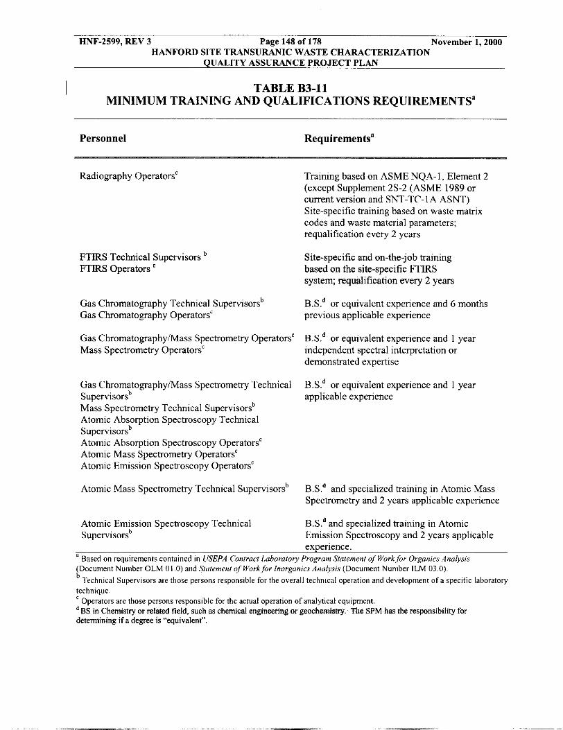
HNF-2599, REV 3 Page 148 of 118 November 1,2000 HANFORD SITE TRANSURANIC WASTE CHARACTERIZATION
QUALITY ASSURANCE PROJECT PLAN
I TABLE B3-11 MINIMUM TRAINING AND QUALIFICATIONS REQUIREMENTS”
Personnel Requirementsa
Radiography Operators‘
FTIRS Technical Supervisors ‘ FTIRS operators
Training based on ASME NQA-1, Element 2 (except Supplement 2s-2 (ASME 1989 or current version and SNT-TC-1A ASNT) Site-specific training based on waste matrix codes and waste material parameters; requalification every 2 years
Site-specific and on-the-job training based on the site-specific FTIRS system; requalification every 2 years
Gas Chromatography Technical Supervisorsb Gas Chromatography OperatorsC
Gas ChromatographyiMass Spectrometry OperatorsC Mass Spectrometry Operators‘
B.S.d or equivalent experience and 6 months previous applicable experience
B.S.d or equivalent experience and 1 year independent spectral interpretation or demonstrated expertise
B.Xd or equivalent experience and 1 year Gas ChromatographyiMass Spectrometry Technical Supervisors’ applicable experience Mass Spectrometry Technical Supervisorsb Atomic Absorption Spectroscopy Technical Supervisorsb Atomic Absorption Spectroscopy Operators‘ Atomic Mass Spectrometry OperatorsC Atomic Emission Spectroscopy OperatorsC
Atomic Mass Spectrometry Technical Supervisors’ B S d and specialized training in Atomic Mass Spectrometry and 2 years applicable experience
B S d and specialized training in Atomic Emission Spectroscopy and 2 years applicable experience.
Atomic Emission Spectroscopy Technical Supervisorsb
a Rased on requirements contained in USEPA Contracr Laboratory Program Staremenl of Work for Organics Analysis (Document Number OLM 01 .O) and Staremenr of Work.for Inorganics Analysis (Document Number ILM 03.0).
technique.
’ RS in Chemistry or related field, such as chemical engineering or geochemishy. The SPM has the responsibility for determining if a degree is “equivalent”.
Technical Supervisors are those persons responsible for the overall technical operation and development of a specific laboratory
Opcrators are those persons responsible for the actual operation of analytical equipment.

HNF-2599, REV 3 Page 149 of 178 November 1,2000 HANFORD SITE TRANSURANIC WASTE CHARACTERIZATION
QUALITY ASSURANCE PROJECT PLAN
0
X
X
0
X
TABLE B3-12 TESTING BATCH DATA REPORT CONTENTS
0 0
X X
X X
0 0
X x
Required Information
X
Batch Data Report Date Batch number Waste container
X X
name and/or
code Implementing procedure (specific version used) Container type
Videotape reference
Imagmg check Camera Check Audio check QC check of scales
QC documentation Description of liners and layers of confinement (if possible) Indication of vented rigid liners Description of container contents
Visual Verlfication 1 R a d i g ~ % cchni ue
Visual Examination
Radio as QC Check waphy
Comments
Summary Category Group included m waste matrix code
cited contains more than one method, od used must also be cited. Can use revision , date, or other means to track specific version
used. Drums, Standard Waste Box, Ten Drum Overpack, etc. Reference to Videotape(s) applicable to each container. For visual examination (for
cterization) of newly generated waste, tape not required if two tramed operators
Available documented evidence calibrated scale(s) were used. Only applicable if items are weighed during the visual examination.
Only reqoued for containers with ngid liners. If RTR is used to verify, indude in Teshng Batch Data Repoq. Provide enough detail for verificatlon of esbmated weigh for the 12 waste matrix parameters.

Page 150 of 178 HANFORD SITE TRANSURANIC WASTE CHARACTERlZATlON
November 1,2000 HNF-2599, REV 3
L U A L l T Y ASSURANCE PROJECT PLAN
Required Information
ferification hat the )hysical form natches the waste stream lescription and Waste Matrix ,ode indicatlon of iealed :ontainers > 1L Amount of free liquids Estimated weights for the 12 waste matrix parameters Container gross weight Container empty weight Comments Reference to 01 copy of associated NCRs, if any Visual examination expert decisions Verify absence of prohibited items operator signature and
Radio graphy
X
X
X
X
X
0
X X
visual examination + Data review checklists Legend
Visual Examination m QC Check
on Radiography
X
X
X
X
X
0
X X
X
X
X
X
X
Visual Verification
e# - (Rewle$gel'
echnique X
__ X
X
X
X
0
X X
X
X
X
Comments
3ummary Category Group included in waste mab :ode.
Table B3-1 lists waste matrix parameters.
Established container weights can be used.
Copies of associated NCR's must be available.
Only applicable if vlsual examination expert is consulted during visual examination.
2 signatures required for Visual Verification of Acceptable Knowledge.
when visual examination expert is cowulted.
X--Required in batch data report 0- Required in batch data report, but optional in submittal to permittee.

HNF-2599, REV 3 Page 151 of 178 November 1,2000 HANFORD SITE TRANSURANIC WASTE CHARACTERIZATION
QUALITY ASSURANCE PROJECT PLAN
Requked Information
Batch Data Report Date Batch number Waste stream name andior number Waste Mamx code Procedure (specific version used) Container number Container type Sample matrix and @e Analyses requested and laboratory Point of origin for EYke ._ . Sample number .. Sample m e Sample Location
Sample preservation Person collecting sample Person attaching custody seal ,
Chain of custody record Sampling equipment numbers Sampling equipment numbers Cross-reference of sampling equipment numbers with associated cleaning batch numbers Drum age Equilihration time Veri&m#im of
TABLE B3-13 SAMPLING BATCH DATA REPORT CONTENTS
Headspace Gas X
X 0
X
X 0 X
X
X
X X 0
X
X
0
X
X
X
__ 0
0 0 0.
Solid Sampllng
X
X 0
X
X
X 0 X
X
X
X X 0
X
X
0
X
X
__ X
X
Comments
Summary Category Group included in waste mamx code.
If procedure cited contains more than one method, the method used must also be cited. Can use revision number, date, or other means to track specific version used.
Drums, Standard Waste Box, Ten Drum Overpack, etc.
Locahon where sample was taken (e.g., building number, room).
Locatlon within container where sample is taken. For HSG, specify what layer of confinement was sampled. For solids, physical location w i t h container.
May or may not be the same as the person collecting the sample. Original or copy is allowed.
For disposable equipment, a reference to the lot.
For disposable equipment, a reference to the lot.
As applicable to the equipment used for the sampling. For disposable equipment, a reference to the lot and procurement records to support cleanliness is sufficient.
Only applicable to contamers

HNF-2599, REV 3 Page 152 of 178 November 1,2000 HANFORD SITE TRANSURANIC WASTE CHARACTERIZATION
QUALITY ASSURANCE PROJECT PLAN
Required Information
Verification that sample volume taken is small in comparison to thi available volume Scale Calibration Depth of waste
Calculation of core recovery
Co-located core description
Time between coring and sub- sampling OVA calibration and reading Field Records
Reference to or copy of associate NCRs, If any Operator Signature and &I and time of sampling Data review checklists Leeend
Headspace GSS
0
0
X
X
X
X
~
Solid
0 X
~
X
__ X
~
X
~
X
~
X
__ X
___ X
Comments
Must include headspace gas volume when it can be estimated.
For newly generated waste, if a sampling method other than coring is used, this is replaced by documentation that a representative sample - has been -. taken. - For newly generated waste. i f a sampling method other than . . coring is used, this is replaced by documentation that a representative sample has been taken. For newly generated m'aste. i f a sampling method o&;r &n . - coring is Led, this is replaced by documentation that a QC
~
sample has been taken. Only applicable to coring.
Only applicable to manifold systems. Must be done in . .. accordance with manufacturer's specifications. .Must contain the following as applicable to the sampling method used collection problems, sequence of sampling collection, inspection of the solids sampling area, inspection ot the solids sampling equipment, coring tool lest, random location of subsample, caniswr pressure. and ambient temperature and pressure. Copies of associated KCRs muct he available.
I
X- Required in batch data report 0- Required in batch data report, but optional in submittal to permittee

HNF-2599, REV 3 Page 153 of 178 November 1,2000 HANFORD SITE TRANSURANIC WASTE CHARACTERIZATION
QUALITY ASSURANCE PROJECT PLAN
X
TABLE B3-14 ANALYTICAL BATCH DATA REPORT CONTENTS
X
Required Information
Batch Data Report Date-.- . -. _. - Batchnumber . - Sample number? QC designation for - sample Implementing procedure (specific version used)
Q0C sample results Sample data forms
Chain of custody G a s canister tags Sample preservation Holding time Cross-reference of field numbers to laboratory sample numbers Date and time analyzed Confirmation of spectra used for results TIC evaluation Reporting flag, if any Case narrative Reference to or copy of associated NCR's, if any .. Operator signature and analysis date Data review checklists Legend
Headspaee Gas z X
X X I X
Comments
If procedure cited contams more than one method, the method used must also be cited. Can use revision number, date, or other means to track specific version used
Form should contain reduced data for target analytes and TICS. Origiqal or copy. Original or copy.
Analyst must qualitatively evaluate the validity of the results based on the spectra. Can be implemented as a check box for each sample.
Table B3-15 lists applicable flags.
Copes of associated NCRs must be available.
X- Required in batch data report 0- Required in batch data report, but optional in submittal to permittee

HNF-2599, REV 3 Page 154 of 178 November 1,2000 HANFORD SITE TRANSURANIC WASTE CHARACTERIZATION
QUALITY ASSURANCE PROJECT PLAN
E J J
TABLE B3-15 DATA REPORTING FLAGS
pnor to dilution corrections (Metals) Analyte exceeds calibrahon curve (OrganicsEIeadspace gases) Analyte less than PRQL, but greater than or equal to MDL (OrganicdHeadspace gases) Analyte greater than or equal to IDL, but less than 5 times the IDL before diluhon
INDICATOR DATA FLAG
U D
2 H
B B
1 Analyte detected in blank (OrganicdHeadspace gases) 1 Analyte blank concentration greater than or equal to 20 percent of sample concentration
correchon (Metals) Analyte was not detected and value is reported as the MDL (IDL for Metals) Analyte was quantitated from a secondary dilution, or reduced sample aliquot (OrganicsEIeadspace gases) One or more QC samples do not meet acceptance critena Holding time exceeded
174 175 176 177
> 50% of mass 95 5 to 9% ofmass 174 >95%but<lOl%ofmass 174 5 to 9% ofmass 176
TABLE B3-16 4-BROMOFLUOROBENZENE NDANCE CRITERIA FOR
HEAD CIMS
Mass I Ion Abundance Criteria 40% of mass 95
ass 95 peak, 100% relative abundance
5 to 9% of mass 95

HNF-2599, REV 3 Page 155 of 178 November 1,2000 HANFORD SITE TRANSURANIC WASTE CHARACTERIZATION
QUALITY ASSURANCE PROJECT PLAN
B4
B4-1 Introduction
WASTE CHARACTERIZATION USING ACCEPTABLE KNOWLEDGE
The WIPP-WAP, which incorporates the applicable sections of the regulations in 40 CFR Parts 260 through 265,268, and 270, authorizes the use of AK in appropriate circumstances by waste generators, or treatment, storage, or disposal facilities to characterize hazardous waste.
I AK is described in Waste Analysis: USEPA Guidance Manualfor Facilities That Generate, Treat. Store and Dispose ofHazardous Waste (USEPA, 1994b). AK, as an alternative to sampling and analysis, can be used to meet all or part of the waste characterization requirements
I under the RCRA (USEPA, 199413).
The TRU Project uses AK to assign waste matrix codes and USEPA hazardous waste numbers to waste streams and to determine the physical form of waste (waste material parameter) and radionuclides present in the waste. The collection and use of AK information applies to both retrievably stored and newly generated TRU waste streams.
I
AK includes a number of techniques used to characterize TRU waste, such as process knowledge, records of analysis acquired prior to RCRA, and other supplemental sampling and
I analysis data (USEPA, 1994b). Radiogaphy andor VE, headspace-gas sampling and analysis, and homogeneous waste sampling and analysis (see Section B1) are used to acquire supplemental sampling and analysis data to meet the requirements of the QAPjP. AK is used in TRU waste characterization activities in three ways:
e
Sampling and analysis is performed to confirm AK and to provide data for updating and modifying initial AK assessments when required. Sampling and analysis includes radiography, VE, headspace gas, and homogeneous waste sampling and analysis. TRU waste streams shall undergo applicable provisions of the AK process prior to shipment of waste to WIPP.
B4-2 AK Documentation
To delineate TRU waste streams To assess if TRU heterogeneous debris wastes exhibit a toxicity characteristic To assess if TRU wastes contain listed waste constituents. I
The AK information progresses from general facility information (TRU waste management program information) to more detailed waste-specific information (TRU waste stream information). Traceability of AK information for select containers is maintained. The consistent presentation of AK documentation, including completeness and adequacy, is verified
I by internal and external audits. The following sections of the QAPjP identify the information required to characterize TRU waste using AK. WMH-400, Section 7.1.9, describes the methodology for compliance with requirements for compiling, confirming, and controlling Ax information. The TRU Project will, as necessary, supplement the required AK records with additional information (see Section B4-2c). The AK information applies to both retrievably stored and newly generated waste streams.
. .. . ..-

HNF-2599, REV 3 Page 156 of 178 November 1.2000 HANFORD SITE TRANSURANIC WASTE CHARACTERIZATION
QUALITY ASSURANCE PROJECT PLAN
B4-2a TRU Waste Management Program Information
The overview of the TRU Project and its TRU waste management operations is a part of the auditable AK records, HNF-3461, “Hanford Site Transuranic Waste Management Program Acceptable Knowledge Documentation for Retrievably Stored Contact-Handled Waste.” The auditable record clearly defines waste categorization method and terminology, provides a breakdown of the types and quantities of TRU waste that are generated and stored at the Hanford Site, and describes how waste is tracked and managed, including historical and current operations. Information related to the TRU waste certification procedures and the types of documentation (e.g., waste profile forms) used to summarize AK is provided. The following information is included as part of the AK written record:
0 Map of the site with the areas and facilities involved in TRU waste generation, treatment, and storage identified
Facility mission description as related to TRU waste generation and management
Description of the operations that generate TRU waste
0
0
0
0
Waste identification or categorization methods used.
Types and quantities of TRU waste generated, including historical generation through future projections
Correlation of waste streams generated from the same building and process, as appropriate
0
0 Waste certification procedures for retrievably stored and newly generated wastes to be sent to the WIPP facility.
B4-2b TRU Waste Stream Information
The TRU Project compiles an auditable record of all process information and data that support the AK used to characterize each waste stream. At a minimum, the waste process information includes the following written information:
0 Area(s) and/or building(s) from which the waste stream was or is generated
Waste stream volume and time period of generation
Waste generating process described for each area and/or building
Process flow diagrams (a description of the waste generating processes, rather than a formal process flow diagram, may be included if this option is justified and the justification is placed in the auditable record)
0
0
0

HNF-2599, REV 3 Page 157 of 178 November 1,2000 HANFORD SITE TRANSURANIC WASTE CHARACTEIUZATION
QUALITY ASSURANCE PROJECT PLAN
0 Material inputs or other information that identifies the chemical content of the waste stream and the physical waste form.
The AK written records include a summary that identifies all sources of waste characterization information used to delineate the waste stream. The basis and rationale for delineating each waste stream, based on the parameters of interest, is summarized and traceable to referenced documents. Assumptions made in delineating each waste stream are identified and justified. If discrepancies exist between required information, all hazardous waste codes indicated by the information for the subject waste stream will be applied. Alternately, the site may choose to justify an alternative assignment and document the justification in the auditable record. The TRU Project procedure, WMH-400, Section 7.1.9, addresses the following AK requirements:
Identifying and assigning the physical waste form of the waste.
Delineating waste streams and assigning Waste Matrix Codes.
Resolving inconsistencies in AK documentation.
Confirming AK information through headspace-gas sampling and analysis, VE and/or radiography, and homogeneous waste sampling and analysis.
Describing management controls used to ensure prohibited items (specified in Section B-lc) are documented and managed.
Ensure radiography and VE acceptance criteria includes a list of prohibited items the operator verifies are not present in each container of waste.
Document how changes to Waste Matrix Codes, waste stream assignment, and associated USEPA hazardous waste numbers are documented for any waste.
Describe how AK is confirmed using VE when addressing newly generated waste.
B4-2c Supplemental AK Information
The TRU Project collects supplemental AK information to support required TRU waste stream information. The supplemental information is included in the AK written record. Supplemental AK documentation that may be used (if available) includes, but is not limited to, the following information:
0
Process design documents (e.g., Title I1 Design).
Standard operating procedures that may include a list of raw materials or reagents, a description of the process or experiment generating the waste, and a description of wastes generated and how the wastes are managed at the point of generation.

HNF-2599, REV 3 Page 158 of 178 November 1,2000 HANFORD SITE TRANSURANIC WASTE CHARACTERIZATION
QUALITY ASSURANCE PROJECT PLAN
e
e
e
e
e
e
e
e
e
e
Preliminary and final safety analysis reports and technical safety requirements.
Waste packaging logs.
Test plans or research project reports that describe reagents and other raw materials used in experiments.
Site databases (e.g., chemical inventory database for Superfund Amendments and Reauthorization Act Title I11 requirements).
Information from site personnel (e.g., documented interviews).
Standard industry documents (e.g., vendor information).
Analytical data relevant to the waste stream, including results from fingerprint analyses, spot checks, or routine verification sampling. This may also include new information acquired apart from the confirmatory process that supplements required information (e.g., VE not performed in compliance with the QAF'jP).
Material Safety Data Sheets (MSDS), product labels, or other product package information.
Sampling and analysis data from comparable or surrogate waste streams (e.g., equivalent nonradioactive materials).
Laboratory notebooks that detail the research processes and raw materials used in an experiment.
All specific, relevant supplemental AK documentation assembled and used in the AK process, whether it supports or contradicts any required AK documentation, is identified and an explanation provided for its use (e.g., identification of a toxicity characteristic). Supplemental documentation may be used to further document the rationale for the hazardous characterization results. Similar to required information, if discrepancies exist between supplemental information and the required information, the site will apply all hazardous waste codes indicated by the supplemental information to the subject waste stream unless an alternative assignment can be justified. Alternate assignment, if used as an option, will be justified and documented in the auditable record.
B4-3 AK Training, Procedures and Other Requirements
The TRU Project ensures the proper development and use of AK information by implementing controls over the three major phases of program implementation; 1) compiling the required and supplemental AK documentation in an auditable record; 2) confirming and updating AK information using radiography and/or VE, headspace-gas sampling and analysis and homogeneous waste sampling and analysis; and 3) auditing AK records. The following paragraphs address personnel qualification and training requirements, the development of adequatr: PuKpcessprocedures, and specific data quality requirements for AK.

HNF-2599, REV 3 Page 159 of 178 November 1,2000 HANFORD SITE TRANSIJRANIC WASTE CHARACTERIZATION
QUALITY ASSURANCE PROJECT PLAN
B4-3a Qualifications and Training Requirements
TRU Project personnel responsible for compiling AK information, assessing the AK information process, and resolving discrepancies associated with AK processes or information are qualified and trained prior to performing their respective duties. The TRU Project training program is described in WMH-400, Section 1.2.2. TRU Project training addresses the following areas:
WIPP-WAP 0 WIPP-WAC
State and federal RCRA regulations associated with solid and hazardous waste characterization Discrepancy resolution and reporting processes Procedures associated with waste characterization using AK.
B4-3b AK Assembly, Compilation, and Confirmation Procedures and Required Administrative Controls
The TRU Project has developed and implemented an AK procedure, which ensures consistent application of the AK process and requirements. WMH-400, Section 7.1.9, describes the process for assembling AK information. This procedure describes the following criteria:
The specific methodology used to assemble AK records, including documenting the origin of the documentation, how it will be used, and any limitations associated with the information.
The process used for compiling the required AK record.
The process that ensures unacceptable wastes (e.g., reactive, ignitable, corrosive) are identified and segregated from TRU waste populations sent to WIPP.
The process used to evaluate AK and resolve discrepancies. If different sources of information indicate different hazardous wastes are present, all sources of information will be included in the records and the site will conservatively assign all potential hazardous waste codes unless an alternative assignment is made and justified in the auditable record. The assignment of the hazardous waste codes will be traceable in the auditable record to all required documentation.
The process used to identify hazardous wastes and assign the appropriate hazardous waste codes to each waste stream. The following are minimum baseline requirements/standards that the procedure includes to ensure comparable and consistent characterization of hazardous waste:
0
A compilation of the required information in an auditable record
A review of the required information to determine if the waste is listed under the WAP (incorporating 40 CFR 261h Subpart D

HNF-2599, REV 3 Page 160 of 178 November 1,2000 HANFORD SITE TRANSURANIC WASTE CHARACTERIZATION
QUALITY ASSURANCE PROJECT PLAN
. A review of the required information to determine if the waste may contain hazardous constituents included in the toxicity characteristics specified in the WAP (incorporating 40 CFR 261), Subpart C. A provision that if a toxicity characteristic contaminant is identified and is not included as a listed waste, the toxicity characteristic code will be assigned unless data are available that demonstrate that the concentration of the constituent in the waste is less than the toxicity characteristic regulatory level. When data are not available, the toxicity characteristic hazardous waste code for the identified hazardous constituent will be applied to the waste stream.
0 For newly generated waste, hazardous waste characterization using AK will be accomplished prior to packaging the waste.
The process used for confirmation of AK in accordance with Section B4-3d
The process used to provide a cross reference to the applicable summary category group (e.g., S3000, S4000, and S5000) to verify all of the required confirmation data has been evaluated and the proper hazardous waste codes have been assigned.
0 I
0 The process that ensures that results of audits of the TRU waste characterization program at the site are available in the records.
Furthermore, TRU Project procedures specify the administrative controls used to ensure that prohibited items are documented and managed. The following elements are addressed by procedures associated with administrative controls:
0 The identity of the organization(s) responsible for compliance with administrative controls.
0 The identity of the oversight procedures and frequency of actions to verify compliance with administrative controls.
The OJT specific to administrative control procedures.
The provision that personnel may stop work if noncompliance with administrative controls is identified.
0
0
0 A nonconformance process that complies with the requirements in Section B3 of the QAPjP to document and establish corrective actions.
As part of the corrective action process, assess the potential time frame of the noncompliance, the potentially affected waste population(s), and the reassessment and recertification of those wastes.
0

HNF-2599, REV 3 Page 161 of 178 November 1,2000 HANFORD SITE TRANSURANIC WASTE CHARACTERIZATION
QUALITY ASSURANCE PROJECT PLAN
B4-3c Assembling an AK Record and Delineating the Waste Stream
Figure B4-1 provides an overview of the process for assembling AK documentation into an auditable record. TRU Project procedure, WMH-400, Section 7.1.9, describes the process for assembling AK information and assures compliance with the following criteria:
0 AK information is compiled in an auditable record, including a road map for all applicable information.
The overview of the Hanford Site and TRU waste management operations in the context of the Hanford Site mission is correlated to specific waste stream information.
0 Correlations between waste streams, with regard to time of generation, waste generating processes, and TRU Project facilities are clearly described. For newly generated wastes, the rate and quantity of waste to be generated will be defined.
0 A reference list is provided that identifies documents, databases, QA protocols, and other sources of information that support the AK information.
Container inventories for TRU waste currently in retrievable storage are delineated into waste streams by correlating the container identification to all of the required AK information and any supplemental AK information.
B4-3d Confirmation of AK Information
Waste characterization of retrievably stored waste (that is, radiography or VE, headspace- gas sampling and analysis, and homogeneous sampling and analysis) is used to confirm AK information. All retrievably stored TRU waste containers are sampled and analyzed for headspace gas and undergo either NDE by RTR or VE to confirm the Waste Matrix Code Ckmp and waste stream and certify compliance with the QAPjP. If retrievably stored waste must be repackaged for confirmation of AK or ddue to lack of sufficient AK, VE of the waste during the repackaging using the VE technique or VE in lieu of radiography is used to confirm AK information rather than radiography. Figure B4-2 illustrates the process the TRU Project uses to confirm AK information.
Waste characterization for newly generated waste (that is, VE during packaging, total metal analysis and headspace-gas sampling and analysis, if appropriate) is used to confirm AK. For newly generated waste, the site confirms AK information by performing and documenting VE (using the VE technique) prior to or during waste packaging. For newly generated waste, the following requirements are addressed in TRU Project procedures:
0
0 responsible organization(s) 0 administrative process controls
material inputs to process - scope (e.g., waste streams) and purpose
pDcess controls and range of operation that affect final hazardous waste cbazketization . .
HNF-2599, REV 3 Page 162 of 178 November 1,2000 HANFORD SITE TRANSURANIC WASTE CHARACTERIZATION
QUALITY ASSURANCE PROJECT PLAN
e
e
e
e reporting and records management.
The TRU Project performs a reevaluation of AK if radiography or VE results lead to
rate and quantity of the hazardous waste generated list of applicable operating procedures relevant to the hazardous waste characterization process knowledge verification sampling (e.g., headspace-gas sampling andor homogeneous waste annual sampling); and
I reassignment of a different Waste Matrix Code4hwp. The TRU Project procedures describe how the waste is reassigned, AK is reevaluated, and appropriate hazardous waste codes are
I assigned. If a waste must be assigned to a different Waste Matrix Code, the following steps are taken to reevaluate AK:
e Existing information is reviewed based on the container identification number and document all differences in hazardous waste code assignments.
If differences exist in the hazardous waste codes previously assigned, the information is reassessed and all required AK information (see Section B4-3b) associated with the new designation is documented.
All sampling and analytical data associated with the waste is reassessed and documented.
e
e
I e The reassignment of the Waste Matrix Code Gkq- is documented and verified, (e.g., -verification that the waste was generated within the specified time period, area and buildings, waste generating process, and that the process material inputs are consistent with the waste material parameters identified during radiography or VE).
All changes to AK records are recorded
If discrepancies exist in the AK information for the reassigned Waste Matrix CodeCikwp, the segregation of the container is documented, and the actions necessary to fully characterize the waste are defined.
0
I
Potential toxicity characteristics for base materials that compose TRU heterogeneous debris (SSOOO) waste are determined by AK without destructive sampling and analysis. The TRU Project assigns a Waste Matrix Code and waste stream to each container of waste using AK. In lieu of confirmatory sampling and analytical or other data to the contrary (including headspace gas and total/TCLP analysis of soliddsoils), the toxicity characteristic hazardous waste codes are assigned based on the presence of the constituent identified by AK, regardless of the quantity or concentration, except as allowed in B-3d. Radiography or VE is used to confirm the waste matrix code and waste stream identified using AK. If the waste stream designation is so detailed that the specific components cannot be differentiated by radiography (e.g., a waste stream based on a specific type of plastic), the waste stream confirmation is not performed and this omission is explained in the auditable record. TRU Project procedures describe how

HNF-2599, REV 3 Page 163 of 178 November 1,2000 HANFORD SITE TRANSURANIC WASTE CHARACTERIZATION
QUALITY ASSURANCE PROJECT PLAN
discrepancies in the Waste Matrix Code are recorded and additions to hazardous waste codes are documented (see Section B4-3b).
Headspace-gas sampling and analysis is conducted on all TRU waste to be sent to the WIPP facility. Headspace-gas data is used to confirm the presence or absence of VOCs identified using AK.
The TRU Project uses AK to identify spent solvents associated with each TRU waste stream or waste stream lot. Headspace gas data is used to confirm AK concerning the presence or absence of F-listed solvents and concentration of applicable toxicity characteristic solvents. The TRU Project confirms the assignment of F-listed hazardous waste codes by evaluating the average concentrations of each VOC detected in container headspace gas for each waste stream or waste stream lot using the UCL90. The UCLOO for the mean concentration is compared to the PRQL for the constituent. If the UCLqo for the mean concentration exceeds the PRQL, the AK information is reevaluated and the potential source of the constituent is determined. Documentation is provided to support any determination that F-listed organic constituents are associated with packaging materials, radiolysis, or other uses not consistent with solvent use. If the source of the detected F-listed solvents can not be identified, the appropriate spent solvent hazardous waste code is conservatively applied to the waste stream. In the case of applicable toxicity characteristic VOCs and nontoxic F003 constituents, the site may assess whether the headspace gas concentration would render the waste nonhazardous for those characteristics and change the initial AK determination accordingly.
Hazardous wastes associated with S3000 and S4000 waste streams are verified based on the results of the total/TCLP analysis of a representative homogeneous waste sample. If discrepancies between the results obtained from homogeneous waste sampling and analysis and headspace-gas sampling and analysis exist (e.g., a VOC is detected in the solidified waste but not in the headspace), the most conservative results are used to verify AK and assign hazardous waste codes, as applicable. As with headspace gas, if the total/TCLP results indicate that the concentration of a characteristic waste or nontoxic constituent of an F003 waste is below regulatory levels, the hazardous waste code assigned initially by AK may be changed as part of the confirmatory process. Otherwise, if an F-listed waste constituent is detected, the appropriate hazardous waste code is applied.
If the confirmatory process determines that the source of the F-listed constituent is a spent solvent used in the process or is determined to be the result of mixing a listed waste with a solid waste during waste packaging, or applicable toxicity characteristic or nontoxic F003 wastes are present in excess of regulatory levels, the TRU Project will either assign the applicable listed hazardous waste code to the entire waste stream or segregate the drums containing detectable concentrations of the solvent into a separate waste stream and assign applicable hazardous waste codes. The TRU Project will document, justify, and consistently delineate waste streams and assign hazardous waste codes based on site-specific requirements and state-enforced agreements.
To determine the mean concentration of solvent VOCs, all headspace-gas data and homogeneous waste data for a waste stream or waste stream lot (e.g., the portion of the waste stream that is characterized as a unit) are used, including data qualified with a 'J' flag (e.g., less than the PRQL but greater than the MDL) or qualified with a 'U' flag (e.g., undetected). For data @ified.witb a 'U' flag, one-half the MDL is used in calculating the mean concentration.

HNF-2599, REV 3 Page 164 of 178 November 1,2000 HANFORD SITE TRANSURANIC WASTE CHARACTERIZATION
QUALITY ASSURANCE PROJECT PLAN
Because listed wastes are not defined based on concentration, the TRU Project will not remove hazardous waste codes assigned using AK if hazardous constituents are not detected in the headspace gas or solids/soil analysis.
TRU headspace gases and homogeneous waste matrices may contain one or two constituents (e.g., carbon tetrachloride and l , l , 1 -trichloroethane) at concentrations that are orders of magnitude higher than the other target analytes. In these cases, samples are diluted to remain within the instrument calibration range for the elevated constituents. Sample dilution results in elevated MDLs for the constituents with elevated concentrations. Only the concentrations of detected constituents are used to calculate the mean for the purpose of assigning F-listed hazardous waste codes. Because the presence or absence of F-listed solvents cannot be confirmed based on the artificially high MDLs that are caused by sample dilution, data flagged as 'U' and showing an elevated MDL are not used in calculating the mean concentration.
B4-3e AK Data Quality Requirements
I The DQOs for sampling and analysis techniques are provided in Section B3 of the QAPjP. Analytical results are used to confirm the characterization of wastes based on AK. To ensure that the AK process is consistently applied, the TRU Project imposes the following data quality requirements for AK documentation:
0 Precision ~ The qualitative determinations, such as compiling and assessing AK documentation, do not lend themselves to statistical evaluations of precision. Therefore, precision requirements are not established for AK.
Accuracy - Accuracy is the degree of agreement between an observed sample result and the true value. The percentage of waste containers that require reassignment to a new waste matrix code and/or designation of different hazardous waste codes based an the reevaluation of AK and sampling and analysis data will be reported as a measure of AK accuracy.
Completeness - Completeness is an assessment of the number of waste streams or number of samples collected to the number of samples determined to be useable through the data validation process. The AK record will contain 100 percent of the required information (see Section B4-2). The usability of the AK information will be assessed for completeness during audits.
Comparability - Data are considered comparable when one set of data can be compared to another set of data. Comparability is ensured through meeting the training requirements and complying with the minimum standards outlined for procedures that are used to implement the AK process. The TRU Project establishes and assigns hazardous waste codes in accordance with Section B4-4 and provides this information to other sites that store or generate similar waste streams.
0
0
0
0 Representativeness - Representativeness expresses the degree to which-sample data accurately and precisely represent characteristics of a population. Repsentativeness is a qualitative parameter that yill.besetisfied by. ensuring

HNF-2599, REV 3 Page 165 of 178 November 1,2000 HANFORD SITE TRANSURANIC WASTE CHARACTERIZATION
QUALITY ASSURANCE PROJECT PLAN
that the process of obtaining, evaluating, and documenting AK information is performed in accordance with the minimum standards established in Section B4 of the QfPjP. In addition, the TRU Project assesses and documents the limitations of the AK information used to assign each hazardous waste code (e.g., purpose and scope of information, date of publication, type and extent to which waste parameters are addressed).
I
The TRU Project addresses quality control by tracking performance with regard to the use of AK by: 1) assessing the frequency of inconsistencies among information, and 2) documenting the results of AK confirmation through radiography or VE, headspace-gas analyses, and homogeneous waste analyses. In addition, the AK process and waste stream documentation is evaluated through internal assessments by quality assurance organizations and
I assessments by auditors or observers external to the organization (e.g., CAO, NMED, USEPA).
B4-3f Audits of AK
External Audits - The CAO will conduct an initial audit of the TRU Project programs certification prior to certifying the site for shipment of TRU waste to the WIPP facility. The initial audit will establish an approved baseline that will be reassessed annually by CAO. The annual audits will verify continued compliance with the requirements specified in the WAP. These audits will verify compliance with the compilation, application, and interpretation requirements of AK information specified in the WAP, and evaluate the completeness and defensibility of AK documentation related to hazardous waste characterization. Section B6 of the WAP provides a description of the overall audit program.
Internal Audits - In addition to the initial and annual audits conducted by CAO, the SQAO will conduct independent audits/assessments of the AK information process. An overall program audit of the AK process will be conducted on an annual basis. Auditors will evaluate compliance with TRU Project procedures for developing the AK record. A completeness review will evaluate the availability of all required TRU waste management program information and TRU waste stream information (see Sections B4-2a and B4-2b). Records will be reviewed for correlation to specific waste streams and the basis for characterizing hazardous waste. Auditors will verify that the AK records include all required information and that all potential hazardous waste codes have been conservatively applied. The audit process utilized will be consistent with the methodology used by CAO (e.g., the methodology described in Figure B4-3 and Section B6). The TRU Project AK audit checklists will include the following criteria to be assessed during internal audits:
The process used to compile, evaluate, and record AK is implemented.
Personnel qualifications and training are complete and documented.
The required AK documentation specified in Section B4-2 has been compiled in an auditable record.
The procedure requirements specified in Section B4-3 have been developed and implemented.

HNF-2599, REV 3 Page 166 of 178 November 1,2000 HANFORD SITE TRANSURANIC WASTE CHARACTERIZATION
QUALITY ASSURANCE PROJECT PLAN
The process for assigning hazardous waste codes to waste streams in accordance with Section B4-3.
The process for resolving discrepancies in AK documentation in accordance with Section B4-3.
The process for confirming AK information through: a) radiography or VE, b) headspace gas sampling and analysis, and c) homogeneous waste sampling and analysis in accordance with Section B4-3.
Verification that results of audits of the TRU waste characterization program are available in TRU Project records.
Members of the TRU Project audit team will be knowledgeable regarding the AK I information process, RCRA regulations, USEPA guidance regarding the use of AK for waste
characterization, and the WAF'. Audit team members will be independent of all TRU waste management operations being audited. During audits of the AK process, auditors will evaluate AK documentation for at least one waste stream from the Summary Category Group(s) and will audit AK traceability for at least one container from the audited Summary Category Group(s). All deficiencies in the AK documentation will be included in the audit report.
B4-4 Additional Final Confirmation of AK at the WIPP Facility
Prior to notifying the TRU Project that a waste stream can be shipped to the WIPP facility, the permittees will review the WSPF, the WWIS and associated characterization information summary (e.g., summary reports and DQO reconciliations) to ensure that radiography or VE, headspace-gas sampling and analysis data, and homogeneous waste sampling and analysis data confirm hazardous waste characterization made using AK. The TRU Project will provide all of the required data associated with waste stream characterization, including summary AK information, radiography or VE, headspace gas sampling and analysis, and homogeneous waste sampling and analysis results addition, the TRU Project will designate the assigned hazardous waste codes for the waste stream on the WSPF. The WWIS and associated
compared to the hazardous waste codes specified on the WSPF. As part of the reconciliation of DQOs (see Section B3-10), the TRU Project tracks and reports changes to hazardous waste characterizations. If data consistently indicates that discrepancies with AK information were identified at the TRU Project (and were subsequently reconciled), the TRU Project will reassess the materials and processes that generate the waste, and resubmit waste stream profile information and implement their corrective action system. If review of a WSPF and associated waste characterization data reveal nonconformance with AK requirements as described in Section B3 (e.g., project level nonconformance), the waste will not be shipped to WIPP until corrective action is taken as specified in Section B3.
I characterization information summary will be evaluated as illustrated in Figure B4-2 and
Any drum with unresolved discrepancies associated with hazardous waste characterization will not be shipped to the WIPP until the discrepancies are resolved. The
I permittees will require the TRU Project to reassess the materials and processes that generate the waste, and beadspace-gas sampling and analysis, radiography or VE, and homogeneous waste sampIing.ndanalysis. All shipments of the subject waste stream. will ceaseuntil the corrective

HNF-2599, REV 3 Page 167 of 178 November 1,2000 HANFORD SITE TRANSURANIC WASTE CHARACTERIZATION
QUALITY ASSURANCE PROJECT PLAN
I action(s), as necessary, have been implemented and the discrepancy resolved. The permittee will notify NMED when the certification status of a waste stream at a site is revoked. Waste characterization and certification authority will not be reinstated until the TRU Project
permittee. I demonstrates all corrective actions have been implemented and the program is reassessed by the

HNF-2599, REV 3 Page 168 of 178 November 1,2000 HANFORD SITE TRANSURANIC WASTE CHARACTERIZATION
QUALITY ASSURANCE PROJECT PLAN
Gather required TRU waste program
information (Section 84-2a)
Gather required TRU waste
stream information (Section 64-2b)
Review waste inventory records and delineate waste streams based on
acceptable knowledge
1 Compile documentat
auditable file for each waste stream Gather any supplemental information (Section 84-2c)
Resolve discrepancies and document resolution within acceptable knowledge
documentation?
(::r:=. equired information Nod-1 insufficient Segregate information wastes for which is
waste? available for ail
available
vds
Emluate informtion for !he purpose of
assigning hazardous waste codes and . waste rniltnx ,?"des
characterization activities (See Figure 84-2)
Audit acceptable knowledge files
(See Figure 84-3)
Figure W-I. Compilation of AccOptable,XmwW@e Dowfwmtatii
- -

HNF-2599, REV 3 Page 169 of 178 November 1,2000 HANFORD SITE TRANSURANIC WASTE CHARACTERIZATION
QUALITY ASSURANCE PROJECT PLAN
Conduct radiography or document waste container contents during packaging
1 ._.... ~~~
physical form ofthe waste different than tliat
Reassign waste 10 proper waste smam -and -
Re-cvxluatc hazardour waste codes determined by acccptable ~
(40CFR 8261.24)
Sample and riirlyze headspace gas for flammable and eon-llanmnble
~~~~ ~
Prepare data packrgcer and ..."_.̂ _-"I_.̂ F_>^
acceptable knowledge" /' ~ .~ ~~~~~~~
Prepare data packages and Is the waste debtis'! " ..LA...."."al"
. . ~
Continued on next page
Figure 84-2 Confirmation of Acceptable Knowledge
1

HNF-2599, REV 3 Page 170 of 178 November 1,2000 HANFORD SITE TRANSURANIC WASTE CHARACTERIZATION
QUALITY ASSURANCE PROJECT PLAN
Continued from previous page
A oes solidified waste
P q & data packager k d waste slrcam orofi1e
.. . ~ ~ . . .~
pmceri and packaging
materials and procedures
c, or extracting in pmcerr or packaging
~
. . .. .-
Add appmpiiale F - codes
(40CFR6261 .31) towas fes~eam
Or
segregate waste containers Witll packaging materials or radiolysis'!
detectable co~~ceiitralions into
separate waste ilrcam
'-.
waste ilream profile
Figure B4-2 (Continued) C o n f i r d Q n of Acceptable Knowledge,'

HNF-2599, REV 3 Page 171 of 178 November 1,2000 HANFORD SITE TRANSURANIC WASTE CHARACTERIZATION
QUALITY ASSURANCE PROJECT PLAN
I FigureB4-3 Acceptable Knowledge A-g
/ all required hazardous waste codes ..~ Nu %-_, indicated by the acceptable knowledge ~~~~ D
~~~ records? l-.. 1,
Does the site _-.. 1. use administrative controls and idl& -.__
written procedures to make hazardous wasle l> N O
determinations on newlv ,,-, /' . -\
I analysis consistent
.\ withthcWAP? , .,
// Areprocedures ,. to docurncnt changes in acceptab%-e-~- ..
knowledge documentation and hazardous waste'--. N~ <., code assignments consislent with the WAP? ,> I .-' '-,, ,.

HNF-2599, REV 3 Page 172 of 178 November 1,2000 HANFORD SITE TRANSURANIC WASTE CHARACTERIZATION
QUALITY ASSURANCE PROJECT PLAN
B5
B5-1 Quality Assurance Project Plans
QUALITY ASSURANCE PROJECT PLAN REQUIREMENTS
I It is the responsibility of the SPM to ensure that the QAF’jP has been developed and implemented to address all of the applicable requirements specified in the WIPP-WAF’. The
incorporates WAF’ requirements including: I WIPP-WAF’ is contained in the Attachment B of the WIPP RCRA Permit. The QAF’jP
s The qualitative or quantitative criteria for determining whether the waste characterization program activities are being satisfactorily performed.
The identity of the organization(s) and position(s) responsible for the implementation of the QAPjP.
References to site-specific documentation that detail how each of the required elements of the characterization program will be performed.
s
s
The QAPjP follows the document format of the WAF’ and is implemented by TRU Project and facility procedures that address TRU waste characterization activities. Table A-1
I lists the procedures that implement the requirements of the QAPjP. The SPM reviews the QAPjP annually and coordinates the review and approval of the revised document. Distribution of the Q N j P and control of changes are described in ” WMH-400, Section 1.4.1, “TRU
I Document Control” (see Table A-I). The SPM ensures that the DOE CAO approves the QAPjP.
I
Prior to the implementation of characterization activities, the SPM will ensure that written procedures have been developed for implementing the requirements of the QAPjP, and the waste characterization program. Procedures ensure that tasks are performed in a consistent manner and achieve the quality required for the quality assurance program. The SPM ensures that procedures meet the organization, format, content, and designation of standard operating procedures described in WMH-400, Sections 2.1.2,2.1.3, and 2.1.6. As a minimum, the following requirements are addressed in site-specific procedures:
s
Scope and purpose Responsible organization(s) Administrative process controls Material inputs to process Process controls and range of operation that affect the proceduralized functions Rate and quantity of the hazardous waste generated List of applicable operating procedures relevant to the process Process knowledge verification sampling (is., headspace-gas sampling and/or homogeneous waste annual sampling), and Management Reporting and Records.
The TRU Project procedures are reviewed for consistency with the QAPjP in accordance with the above-listed requirements.
I

HNF-2599, REV 3 Page 173 of 178 November 1,2000 HANFORD SITE TRANSURANIC WASTE CHARACTERIZATION
QUALITY ASSURANCE PROJECT PLAN
The most recent revision of procedures is available electronically on a network drive. Personnel ensure that they are working to the most up-to-date version of the applicable procedure
I by accessing the electronic version via the \\au002\wmo\wmh-400 share drive or web page or by comparing their hard copy of the procedure to the electronic version.
Procedures include examples of data (e.g., reports, forms, and data validation checklists), as appropriate. Data forms used in the TRU Project are available via the shared drive document system. Each procedure specifies internal review and approval requirements. Facility QA procedures for TRU Project activities (e.g., records management) must be equivalent to project QA plans and procedures.
B5-2 Document Review, Approval, and Control
The SPM will ensure that the preparation, issuance, and change to documents that specify quality requirements or prescribe activities affecting quality for the TRU waste characterization program be controlled to ensure that correct and current documents are used and referenced. The TRU Project will use a document control format consisting of a unique document identification number, current revision number, date, and page number, which will be placed on the individual pages of the document. Qualified and independent individuals will review all TRU Project quality documents prior to approval and issuance. QAPjP reviews will consider the technical adequacy, completeness, and correctness of the QAPjP, and the inclusion of and compliance with the requirements established by the WAP. Appropriate QAPjP approval is indicated by a signature and date page included in the front of the document. As a minimum for TRU Project documents. the SPM will ensure that:
The revisions to site implementing documents are denoted by including the current revision number on the document title page, the revised signature page, and each page that has been revised.
Only revised pages need to be reissued or the entire procedure may be electronically reissued.
A vertical bar, indicating the change to the text, is included along the left-hand margin of the page, except for full document revisions.
Revised document submittals identify the changes, the reason for the changes, and the justification for concluding that the revised contents continue to satisfy the requirements of the quality assurance program.
The QAPjP and implementing document revisions that affect performance criteria or data quality (e.g., sample handling and custody requirements, sampling and/or analytical methods, QAOs, calibration requirements, or QC sample acceptance criteria) other than editorial changes undergo the same level of review and approval as the baseline version of each document.
The QAPjP includes a detailed description of the reporting and approval requirements for changes to approved implementing procedures, including pmxedures for implementing changes to these dociments.
0
0
0
HNF-2599, REV 3 Page 174 of 178 November 1,2000 HANFORD SITE TRANSURANIC WASTE CHARACTERIZATION
QUALITY ASSURANCE PROJECT PLAN
Members of the TRU Project staff are responsible for reporting any obsolete or superseded information to the SPM.
All site-specific changes are evaluated and approved by the SPM and the SQAO before implementation and that the appropriate personnel are notified and the affected documents are revised as necessary.
Changes that affect performance criteria or data quality, and would take the activity out of compliance because they alter a requirement, such as sample handling and custody requirements, sampling and analytical procedures, quality assurance objectives, calibration requirements, or QC sample acceptance criteria are not made without prior approval by DOE CAO.
The TRU Project personnel implement the document control system in accordance with WMH-400, Section 1.4.1. WMH-400, Sections 2.1.2, 2.1.3, and 2.1.6, specify the process for initiating, revising, modifying, reviewing, and distributing project documents and changes to project documents. As potential changes to project information are identified by the SPM, documents will be revised as necessary and distributed to affected organizations in accordance with this procedure.
B6 AUDIT AND SURVEILLANCE PROGRAM
B6-1 Introduction
The SQAO is responsible for developing and implementing an internal audit and surveillance program that will ensure that TRU Project personnel conduct TRU waste
I characterization, including sampling and analysis of waste in accordance with the QAPjP, and the information supplied to satisfy the requirements of Section B-4 is being managed properly. The TRU Project will conduct these audits and surveillances in accordance with WMH-400, Section 3.2.1, “TRU Independent Assessments,” and WMH-400, Section 3.2.2, “TRU Surveillance Program.” The audit and surveillance program provides for:
0
0
0
0
0
Coordination with CAO external audits Audit schedule Assurance of specialized auditor training Selecting audit personnel Reviewing applicable background information Preparing an audit plan Preparing audit checklists Conducting the audit Developing an audit report Following up on audit deficiencies, both internal and external Maintain auditor training and qualification records, and Maintain audit records.

HNF-2599, REV 3 Page 175 of 178 November 1,2000 HANFORD SITE TRANSURANIC WASTE CHARACTERIZATION
QUALITY ASSURANCE PROJECT PLAN
B6-2 Audit Procedures
The above audit procedures define the responsibilities and methodology for planning, scheduling, performing, and reporting internal audits.
B6-3 Audit Position Functions
Audit procedures define audit personnel and technical specialist position functions, I required expertise, and TRU Project requirements.
B6-4 Audit Conduct
Audits will include personnel interviews, document and record reviews, observations of operations, and any other activities deemed necessary by the auditors to meet the objectives of the audit. Observations and deficiencies identified during the audit will be investigated or evaluated to determine if they are isolated conditions or represent a general breakdown of the waste characterization quality assurance program. During audit interviews or audit meetings, personnel may be advised of deficiencies identified within their areas of responsibilities to establish a clear understanding of the identified condition.
.
TRU Project personnel will be given the opportunity to correct deficiencies that can be corrected during the audit period. Deficiencies and observations will be documented and included as part of the final audit report. Those items that have been resolved during the audit (isolated deficiencies that do not require a root a cause determination or actions to preclude recurrence) will be verified prior to the end of the audit, and the resolution will be described in the audit report. Those items that effect quality of the program, and/or the data generated by that program will be documented on a CAR in accordance with WMH-400, Section 3.2.1 and WMH-400. Section 3.2.2.
The corrective action response will include a discussion of the investigation performed to determine the extent and impact of the deficiency, a description of the remedial action taken determination of root cause, and actions taken to preclude recurrence. Refer to WMH-400, Section 1.3.1, “TRU Corrective Action Management” (see Table A-1).
The responsible individual will respond to deficiencies and observations within 30 days after receipt of any CARs and indicate the corrective actions to be taken. If the corrective action has not been completed, the response must indicate the expected date the action will be completed.
In addition to performing internal audits and surveillances, the SPM and SQAO will be responsible for coordination and cooperation with external audit agencies responsible for assessments of the TRU waste characterization program. Interface and coordination actions will include the following:
0 Support annual CAO audits Participate in applicable audit meetings
)I R e W CARs and provide corrective actions
HNF-2599, REV 3 Page 176 of 178 November 1,2000 HANFORD SITE TRANSURANIC WASTE CHARACTERIZATION
QUALITY ASSURANCE PROJECT PLAN
Provide CAR plans within allotted time constraints Close deficiencies prior to waste shipment.
i
.~

HNF-2599, REV 3 Page 177 of 178 November 1,2000 HANFORD SITE TRANSURANIC WASTE CHARACTERIZATION
QUALITY ASSURANCE PROJECT PLAN
C LIST OF REFERENCES
Cochran, William G. 1977. Sampling Techniques. New York, New York, John Wiley & Sons: pp.77-78.
DOE, 1996. DOE Waste Treatability Group Guidance, DOE/LLW ~ 217, Current Revision, Idaho Falls, Idaho, INEL ~ Lockheed Idaho Technologies Company, U S . Department of Energy.
DOE, 1995a. Performance Demonstration Program Plan for the Analysis of Simulated Headspace Gases for the TRU Waste Characterization Program. CAO-95-1076, Current Revision, Carlsbad, new Mexico, Carlsbad Area Office, U.S. Department of Energy.
DOE, 1995b. Performance Demonstration Program Plan for the Analysis of Solid Wastes for the TRU Waste Characterization Program. CAO-95-1077, Current Revision, Carlsbad, New Mexico, Carlshad Area Office, U.S. Department of Energy.
DOE, 1996. TRLJF'ACT-I1 Content Codes (TRUCON), DOE/WIPP 89-004, Current Revision, Waste Isolation Pilot Plant, U.S. Department of Energy, Carlsbad, New Mexico.
DOE, 1997. "Resource Conservation and Recovery Act Part B Permit Application for the Waste Isolation Pilot Planto, Revision 6.5, U.S. Department of Energy.
DOE, 1999a. Waste Isolation Pilot Plant Hazardous Waste Permit, 4890139088-TSDF, Attachment B, including Attachments B1 through B6, Santa Fe, New Mexico, New Mexico Environment Department
DOE, 199913. Quality Assurance Program Document, CAO-94-1012, Current Revision, Carlsbad New Mexico, Carlsbad Area Office, U S . Department of Energy.
EG&G. 1994. Description of the SWEPP Certified Waste Sampling Program for FY-94. Engineering Design File, RWMC-363, Revision 6, Idaho Falls, Idaho, EG&G - Idaho Inc., Idaho National Engineering Laboratory.
I USEPA, 1988, "Compendium Method TO-14, The Determination of Volatile Organic Compounds (VOC) in Amhient Air Using SUMMA Passivated Canister Sampling and Gas Chromatographic Analyses." Compendium of Methods for Determination of Toxic Organic Compounds in Ambient Air. Research Triangle Park , North Carolina, Quality Assurance Division, Environmental Monitoring Systems Laboratory, U S . Environmental Protection Agency.
USEPA, 1992. Specifications and Guidance for Obtaining Contaminant-Free Sample Containers, Directive No. 9240.0 OSA, Washington D.C., Office of Solid Waste and Emergency Response, U.S. Environmental Protection Agency.
USEPA, 1994a. U.S. USEPA Contract Laboratory Program Statement of Work for Organ~csA.u&yi$s, OLM 03.1, Washington D.C., U S . E n ~ m
I
I

HNF-2599, REV 3 Page 178 of 178 November 1,2000 HANFORD SITE TRANSURANIC WASTE CHARACTERIZATION
QUALITY ASSURANCE PROJECT PLAN
USEPA, 1994b, "Waste Analysis at Facilities that Generate, Treat, Store, and Dispose of Hazardous Waste, a Guidance Manual," OSWER 9938.4-03, Office of Solid Waste and Emergency Response, Washington, D.C.
USEPA, 1996. "Test Methods for Evaluating Solid Waste," Laboratory Manual PhysicalKhemical Methods, SW-S46,3rd ed., U S . Environmental Protection Agency, Office of Solid Waste and Emergency Response, Washington, D.C.
Hanford, 1999, "Hanford Site Transuranic Waste Certification Plan" Richland, Washington, WMFSH, Inc.
I
I