engineering calculation cover sheet …specifically, the design strength capacity of the anchor...
TRANSCRIPT

E
ENRON SERVICES, INC.
ENGINEERING CALCULATIONCOVER SHEET
CALCULATION NO. PGE-009-CALC-001 REVISION NO. 5
PURPOSE OF CALCULATION:
Design the components of an anchorage system for the Holtee HI-Storm I OOSA used fuel storage casks thatwill be used at the Diablo Canyon Nuclear Power Plant.
SCOPE OF REVISION:
Revision adjusts the calculation for the layer of steel above to dnchor plates to incorporate results from the steelreinforcement calculation PGE-009-CALC-007. Adjusted Figure 6 to be consistent with the 007 calculation. Revisedsome formats.
REVISION IMPACT ON RESULTS:
No impact.
SAFETY RELATED
PRELIMINARY CALCULATIONE NON-SAFETY RELATED
FINAL
APPROVALS (Print Name and Sign)
ORIGINATOR S. C. Tumminelli Date March 11, 2003
REVIEWER Date
VERIFICATION ENGINEER K. L. Whitmore Date March 11, 2003
APPROVER R. F. Ev e rs "o(e6 --~~ :r ~-A I --'12 Date March 11, 2003
t, JTHER REVIEWER Date- K )THER REVIEWER Date

SHEET 2 OF 29
.I oynENGINEERING CALCULATIONJYtx REVISION STATUS SHEET
-ENERCON SERVICES, INC.
CALCULATION NO. PGE-009-CALC-001
ENGINEERING CALCULATION REVISION SUMMARY
REVISION NO.01
DATE3/28/016/27/01
2
3
11/21/01
12/14/01
01/02/03
03/11/03
DESCRIPTIONInitial issue.
Upgraded from a sizing calculation to a final designcalculation. Added more detail and addressedreviewers comments. Revised version of Appendix Bused and revision of Holtec report for design inputloads. Calculation revised in its entirety. No revisionbars shown. Added appendices DOC- 1 and DOC-2.Made minor grammar and punctuation corrections.Revision reflects conformance to alternate criteriaspecified by the ACI 349-97 code for A36, that is moreappropriate for this material. Incorporated latestrevision of the Holtec cask report.Revised references 4.1.3 and 4.1.4 to latest rev. no.Change is not substantive. Corrected typos this page.All sheets revised to rev. 4 due to pagination.Substantive revisions are to the anchor plate size onsheet 22, and concrete pull out sheets 24 to 28.All sheets show a new revision number. Revised thecalculation for shear and shear friction, sheets 24 to 29.
4
5
CALCULATION SHEET REVISION STATUS
SHEET NO. REVISION NO. SHEET NO. REVISION NO.All sheets upgraded to 1 3,11 3
Revision 1
3-6, 9and 1 2 All sheets420-27 2 All sheets 5
APPENDIX AND ATTACHMENT REVISION STATUS
APPENDIX NO. REVISION NO. ATTACHMENT NO. REVISION NO.
DOC-1 2 N/A N/ADOC-2 2

SHEET 3 OF 29
JOB. NO. PGE-009 DATE March 11, 2003
PROJECT DCPP ISFSI
SUBJECT Embedment Support Structure
CLIENT PG&E-DCPP ORIGINATOR S. C. Turnminelli
ENERCON SERVICES, INC. REVIEWER K. L Whitmore APPROVED R. F. EversCALCULATION NO. PGE-009-CALC-001 REVISION 5
REVIEW SUMMARY SHEET(Enercon Services, Inc. Corporate Standard Procedure # 3.01 paragraph 4.6)
Method of Review:
The changes made in revision 4 of the calculation have been independently reviewed in accordance with
the requirements of ENERCON Corporate Standard Procedure 3.01. The independent verification of the
calculation was performed by a detailed review and check of the entire calculation including a check of
the impact of the changes on the remaining portions of the calculation. This included verification of
inputs, methodology, results and conclusions as well as a check of the mathematical accuracy of the
computations.
Results:
The calculation has been independently verified to be mathematically correct and to be performed in
accordance with license and design basis requirements and applicable codes. Inputs are appropriate and
are obtained from verified source documents. The calculation is sufficiently documented and detailed to
permit independent verification. No assumptions are made other than conservative simplifying
assumptions which are identified and do not require confirmation. The methodology used is appropriate
and consistent with the purpose of the calculation
The rods, couplings, bearing plates and other hardware detailed in the calculation and on drawings PGE-
009-SK-301 and PGE-009-SK-302 have been demonstrated by the analysis documented in the
calculation to be adequate to transfer the loads of the HI-STORM cask to the slab of the spent fuel
storage facility. The design has been shown to be in compliance with the design and license basis
requirements and to be adequate for the Hosgri and Long Term Seismic Program seismic events. In
addition, the embedment support structure has been shown to meet all requirements with regard to
strength, ductility, stiffness and factors of safety.
Thus, the design is compliant with all technical and license basis requirements at Diablo Canyon Power
Plant. In addition, the results and conclusions accurately reflect the findings of the calculation. Thus,
the embedment support structure design is adequate and compliant with all requirements.

JOB. SHEET 4 OF 29____ ___JOB. NO. PGE-009 DATE March 11, 2003
PROJECT DCPP ISFSISUBJECT Embedment Support StructureCLIENT PG&E-DCPP ORIGINATOR S. C. Tumminelli
ENERCON SERVICES, INC. REVIEWER K. L Whitmore APPROVED R. F. EversCALCULATION NO. PGE-009-CALC-001 REVISION 5
1.0 PROBLEM STATEMENT
The purpose of this calculation is to design the components of an anchorage system for the
Holtec HI-Storm 100A used fuel storage casks that will be used at the Diablo Canyon Nuclear
Power Plant. This anchorage system is called the Embedment Support Structure. The used fuel
storage casks are part of an Independent Spent Fuel Storage Installation that will be used to store
irradiated used fuel.
The anchorage system will be embedded in the concrete cask storage pads at the Independent
Spent Fuel Storage Installation site. This calculation identifies load paths and predicts member
performance to determine member sizes and details.
The anchorage system is to provide the following:
* a level surface for the cask to sit upon.
* sixteen (16) receptacles for (16) - 2 inch diameter anchorage studs.
* strength to deliver applied cask loads due to external events to the concrete pad.
2.0 INPUT REQUIREMENTS
2.1 Assumptions
None
2.2 Design Data
Materials
The plates and bars are to be made from ASTM A-36 material.
The receptacles into which the anchor studs thread are to be SA 516 Grade 70, per Holtec
requirements (See Ref. 4.1.4, pg A-5).
The concrete cask storage pad compressive strength is to be 5000 psi.
The spring rate of the round anchor bars is 1.898e6 lb./in. (Ref. 4.1.4, Table 1, pg. 23 and sheet
A-8).
Applied loads
Loads from Holtec report HI-2012618, (Ref. 4.1.4) are as follows (These loads are from analyses
for the Hosgri and Long Term Seismic Program seismic events):

SHEET 5 OF 29
JOB. NO. PGE-009 DATE March 11, 2003PROJECT DCPP ISFSISUBJECT Embedment Support Structure
CLIENT PG&E-DCPP ORIGINATOR S. C. Tumminelli
ENERCON SERVICES, INC. REVIEWER K. L Whitmore APPROVED R. F. EversCALCULATION NO. PGE-009-CALC-001 REVISION 5
* Maximum Net Interface Shear Force is 515 kip (See ref., pg. 9). This is the largest vectorsum of the applied shears at the base of the cask.
* Maximum applied Tensile Load in Embedment Anchor Rods is 62.13 kip (See ref. pg. 9)* Cask Anchor Stud Preload is 157 kip (See ref, pg. 19)
Distance from pad surface to C.G. of cask is 118.5 inches (See ref., pg. 10)
3.0 METHODOLOGY
The detailed descriptions and calculations below will demonstrate the following:
The casks are anchored into the concrete by embedded anchor bars. Anchor plates are attached tothe bottom of these anchor bars to provide adequate bearing area onto the concrete so as to beable to transfer all load by end bearing. Anchorage is designed so as to meet the ductileanchorage provisions of the 10/01/00 Proposed Draft New Appendix B to ACI 349-97, see Ref.4.2.1. Specifically, the design strength capacity of the anchor plate (B.10.1), concrete bearing(10.15.1 and B.4.5.2), and the diagonal tension shear capacity (11.3.1.1) computed in accordancewith the design provisions of ACI 349-97 all exceed the anchor bar required ductile designstrength of 235.63 kips (see Section 6.3) for A36 material per Section B.3.6.2 and Commentary(Ref. 4.2.1.). Furthermore, the minimum ultimate tensile strength which is computed at thereduced section at the thread root of the anchor bar is 125 percent of the minimum yield strength(176.72 kips) of the unreduced gross section of the anchor bar, though the Code only requiresthat it be greater.
The anchor bars are made from A36 steel, which has a well-defined yield plateau. Thus, if anyoverload occurs, the anchor bars will yield before any less ductile failure could occur. Lastly, theminimum yield strength of the anchor bars is more than 250 percent of the computed demandload (62.13 kips) on these bars so as to provide substantial margin against yielding.
The main components of the anchorage system will be comprised of a circular steel EmbedmentSupport Plate, sixteen (16) Couplers used to anchor the Holtec supplied 2 inch Cask AnchorStuds, and sixteen (16) Round Bars (including anchor plates) used to anchor the Couplers. Thesecomponents will be embedded in the concrete pad. The design of the concrete pad is the subjectof a separate calculation. A description of the components sized in this calculation is as follows:
EMBEDMENT SUPPORT PLATE (Figure 1)
The Holtec cask base plate outside diameter is 146 l/2 inches, ± 114 inch (Ref. 4.1.3). The largestdiameter with tolerance is 146 /4 inches. The Holtec 2 inch diameter studs fit into the embedmentplate through holes in the cask flange that are sized at 2 1/4 inches, +1%4, -0 inch (Ref. 4.1.3). Thusthe cask can shift in the holes by 1/2 inch. Therefore the maximum effective diameter of the caskbase plate is 147 1% inches

SHEET 6 OF 29
JOB. NO. PGE-009 DATE March 11, 2003
PROJECT DCPP ISFSI
SUBJECT Embedment Support Structure
CLIENT PG&E-DCPP ORIGINATOR S. C. Tumminelli
ENERCON SERVICES, INC. REVIEWER K. L Whitmore APPROVED R. F. EversCALCULATION NO. PGE-009-CALC-001 REVISION 5
The desire is to have a l2 inch lip on the embed showing regardless of where the cask is placed.
Therefore, the embedment plate must be 148 1/4 inches minimum. Therefore, call for 149 inch ±
1/4 inch diameter. This provides some additional margin for future potential minor changes in
dimensional tolerance.
The bolt circle is 139 1/2 inches. For symmetry, call for 130 ± ¼ inch diameter for the inside.
The concrete pad will slope at approximately 1 % for drainage. Thus, the concrete surface will be
approximately 1 l2 inches higher on one side of the embedment support plate (0.01x149 = 1.49
inches). Call for a 2 inch thick plate to keep the bottom of the embedment support plate below
the concrete surface.
Therefore, the embedment plate dimensions are as follows:
* outside diameter is 149 inches, 4 1/4 inch
* inside diameter is 130 inches, ± 1 inch
* bolt circle diameter is 139 l2 inches, to be located using a template
* plate is 2 inches thick
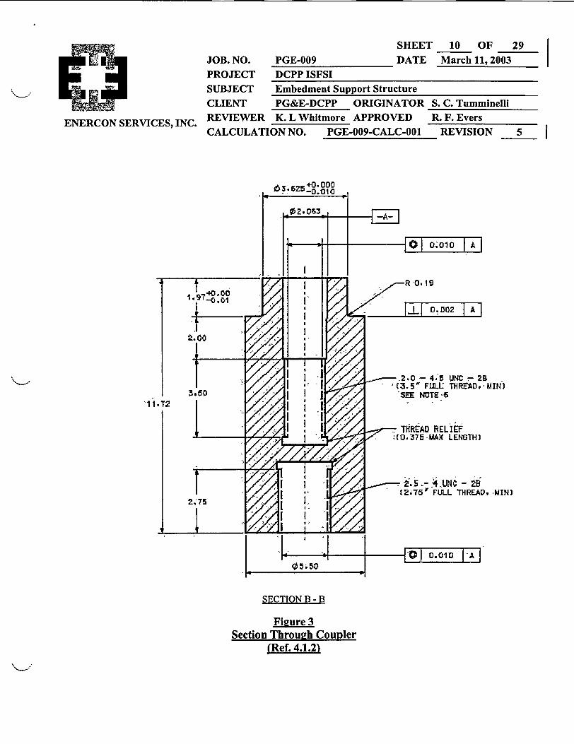
COUPLER (Figures 2 and 3)
Sixteen 5 l/2 inch Couplers are required. Each Coupler will be made with a 2 inch Class 2B
thread to match the Holtec Cask Anchor Stud (Ref. 4.1.4, pg. A-4). The thread length needed is:
Le+2-= 1.397+2x 1= 1.897in.n 4
The Coupler will be designed to have a boss that fits up into a hole in the embedment support
plate. A tight fit is required so that tolerance will be held to a minimum and so that shear may be
delivered without appreciable bending. The threads in the coupler will be started well below the
plate so that the stud can pull the coupler up into bearing with the plate. Relief is provided at the
bottom of the hole to allow for thread run-out and good stud installation practice.
The outside diameter of the coupler was selected to be larger than a heavy hex nut for the threads |
used in the round bar below. It is then evaluated for shear capacity. A threaded hole in the
bottom of the coupler will be provided to accommodate a round bar required that delivers load to
the concrete.

ENERCON SERVICES, INC.
SHEETJOB. NO. PGE-009 DATEPROJECT DCPP ISFSISUBJECT Embedment Support StructureCLIENT PG&E-DCPP ORIGINATOR SREVIEWER K. L Whitmore APPROVED ICALCULATION NO. PGE-009-CALC-001
7 OF 29March 11, 2003
. C. TumminelliL. F. EversREVISION 5j
ROUND BARS (Figure 2)
Sixteen round bars are also required. The bars will mate with the bottom of the Coupler todeliver the cask tensile loads to the concrete pad. The bars will be designed to ensure ductilefailure, i.e., the embedment and concrete strength will have the capability of developing thecapacity of the bar. These bars are the parts of the structure that will demonstrate compliancewith the ductility requirements of ACI 349-97, Appendix B (Ref.4.2.1).
The Holtec calculation for loads includes a spring rate for these bars, see Section 2.2. The barused in that calculation is 2 inches in diameter x 48 inches long. The calculated stiffness of thebar is, k = 1.898 106 lb./in. Any bar used must remain faithful to this stiffness. This calculationwill ensure compliance to this requirement.
The round bars will be embedded deeply into the pad to ensure bar strength and to ensure theconcrete will not fracture under applied load.

SHEETJOB. NO. PGE-009 DATEPROJECT DCPP ISFSISUBJECT Embedment Support StructureCLIENT PG&E-DCPP ORIGINATOR SREVIEWER K. L Whitmore APPROVED RCALCULATION NO. PGE-009-CALC-001
8 OF 29March 11, 2003
. C. Tumminellit. F. EversENERCON SERVICES, INC.
0149' tl/4 L.
0 1 30. + 1/4
0 13S92" B.C. GSEE NOTE 3 /\
REVISION 5 1
A
PLAN VIEWEMBEDMENT SUPPORT PLATE
Figure 1Embedment SulDort Plate
(Ref. 4.1.1)

SHEET 9 OF 29i JOB. NO. PGE-009 DATE March 11, 2003
PROJECT DCPP ISFSISUBJECT Embedment Support StructureCLIENT PG&E-DCPP ORIGINATOR S. C. Tumminelli
ENERCON SERVICES, INC. REVIEWER K. L Whitmore APPROVED R. F. EversCALCULATION NO. PGE-009-CALC-001 REVISION 5
r21-.
82. 88
I i
i i
i ii ii ii ii ii ii ii ii i
10I
I!:IL
i
I
iIIiIIiI
i
I
n r4lT nCOUPLER
l "Ia L. f
iIii'iIiIiI
w ROUND BAR
i LLnLI JL=
2"
4, ANCHOR PLATE
SECTION A-A
Figure 2Section of Embedment Support Plate
Showine Round Bars, Couplers and Anchor Plates(Ref. 4.1.1)
SHEET 10 OF 29
March 11, 2003JOB. NO. PGE-009 DATE
PROJECT DCPP ISFSISUBJECT Embedment Support StructureCLIENT PG&E-DCPP ORIGINATOR S
ENERCON SERVICES, INC. REVIEWER K. L Whitmore APPROVED ICALCULATION NO. PGE-009-CALC-001
+0. 000
_- -ff 1IS1 | R '0.19
'I.l
It2.0 4,
-I '7V 3.SM FUL515I SEE 1
;. C. Tumminelli1. F. EversREVISION 5 I
SECTION B - B
Figure 3Section Through Counler
(Ref. 4.1.2)

SHEET 1 1 OF 29
JOB. NO. PGE-009 DATE March 11, 2003
PROJECT DCPP ISFSI
SUBJECT Embedment Support Structure
CLIENT PG&E-DCPP ORIGINATOR S. C. Tumminelli
RCON SERVICES, INC REVIEWER K. L Whitmore APPROVED R. F. Evers
CALCULATION NO. PGE-009-CALC-001 REVISION 5
4.0 REFERENCES
Reports, Drawings and Industry Literature
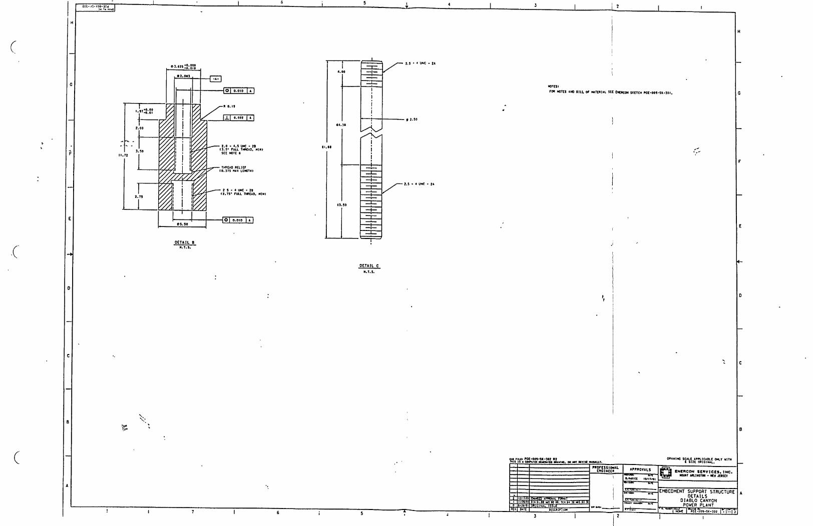
4.1.1. Enercon Sketch No. PGE-009-SK-301, Sh.1, "Embedment Support Structure, Diablo
Canyon Power Plant", see Appendix DOC-1.
4.1.2 Enercon No. PGE-009-SK-302, Sh.1, "Embedment Support Structure Details, Diablo
Canyon Power Plant", see Appendix DOC-1.
4.1.3 Holtec Drawing 3570, Rev.2, "Cask Anchor Stud and Sector Lug Arrangement".
4.1.4 Holtec Report No. HI-201261 8, R5.
4.1.5 Roark's Formulas for Stress and Strain, 6th Edition.
4.1.6 Machinery's Handbook, 26 th Edition, Industrial Press Inc., New York, 2000
4.1.7 Good Bolting Practices, Volume 1: Large Bolt Manual, EPRI. 1987.
4.1.8 ENERCON Calculation PGE-009-CALC-007, "ISFSI Cask Storage Pad Steel
Reinforcement", latest revision.
4.1.9 PG&E Specification, 10012-N-NPG, Rev 2,
Design Codes
4.2.1 ACI 349 - 97, including the proposed revision to Appendix B, dated 10/01/00. See
Appendix DOC-2 for ACI 349 Appendix B.
4.2.2 Steel Construction Manual, 9t Edition, AISC
5.0 CONCLUSION
This calculation concludes that the members as identified in the body of the calculation are in
compliance with design codes and acceptable design practices.
SHEE'JOB. NO. PGE-009 DATEPROJECT DCPP ISFSISUBJECT Embedment Support StructureCLIENT PG&E-DCPP ORIGINATORREVIEWER K. L Whitmore APPROVEDCALCULATION NO. PGE-009-CALC-001
T 12 OF 29March 11, 2003
S. C. TumminelliR. F. Evers
REVISION 5ENERCON SERVICES, INC. I
l~
6.0 CALCULATION
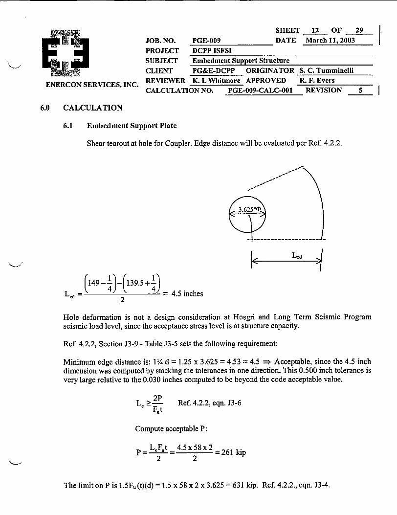
6.1 Embedment Support Plate
Shear tearout at hole for Coupler. Edge distance will be evaluated per Ref. 4.2.2.
VC149 -J1(139.54) (
= 1 4_J = .nches
Led =2
Hole deformation is not a design consideration at Hosgri and Long Term Seismic Programseismic load level, since the acceptance stress level is at structure capacity.
Ref. 4.2.2, Section J3-9 - Table J3-5 sets the following requirement:
Minimum edge distance is: 1 /4d = 1.25 x 3.625 = 4.53 = 4.5 => Acceptable, since the 4.5 inchdimension was computed by stacking the tolerances in one direction. This 0.500 inch tolerance isvery large relative to the 0.030 inches computed to be beyond the code acceptable value.
Le 2PF.t
Ref. 4.2.2, eqn. J3-6
Compute acceptable P:
~LeFut- 4.5x58x2p L2 = 25 = 261 kip2 2
The limit on P is 1.5Fu(t)(d) = 1.5 x 58 x 2 x 3.625 = 631 kip. Ref. 4.2.2., eqn. J3-4.

SHEE'T 13 OF 29
March 11, 2003JOB. NO. PGE-009 DATEPROJECT DCPP ISFSISUBJECT Embedment Support StructureCLIENT PG&E-DCPP ORIGINATOR
REVIEWER K. L Whitmore APPROVED
CALCULATION NO. PGE-009-CALC-001
S. C. TumminelliR. F. Evers
REVISION 5ENERCON SERVICES, INC. I
I
The 1.7 factor permitted by Ref. 4.2.2, Section N8 is not used. Therefore, the design isconservative.
Net capacity per coupler is: 261 kip
Structure capacity is:16x261= 4176kip
as limited by the shear tearout in the embedmentsupport plate at the holes for the coupler.
6.2 Coupler
Material: SA516, Grade 70, FY = 38 ksi (Section 2.2).
The maximum applied shear load is 515 kip applied in friction to both, the surface of theembedment plate steel and the concrete surface (Section 2.2). Since the distribution is not knownbetween the steel shear and the concrete shear, assume it all acts on the steel.
Therefore, the load path is from the plate, to the coupler, to the concrete.
Boss at the top of coupler is 3.625 inch OD, and 2.06 inch ID, (See Figure 3).
Compute shear capacity of coupler as limited by bending of the boss:
Boss Plastic Moment Capacity, Ref. 4.1.5, Table 1, Case 22:
E20 ' 2A= n(RO-R2) = " (1.8125'-1.03
A = 3.494 in2
Distanceto C.G.: y= = 0J=4 (1.81253 -1.033 = 0928 in
3;r 1.81252 -1.032)

SHEETJOB. NO. PGE-009 DATEPROJECT DCPP ISFSISUBJECT Embedment Support StructureCLIENT PG&E-DCPP ORIGINATOR SREVIEWER K. L Whitmore APPROVED RCALCULATION NO. PGE-009-CALC-001
14 OF 29March 11,2003 |
. C. TumminelliR. F. EversREVISION 5
ENERCON SERVICES, INC. I
�� I
.-. Z (Plastic Section Modulus) = 2 x 3.494 x 0.928 = 6.485 in3
and MP = 6.485 x 38.0 = 246.4 in-kip
Using 90% MP =Ma11 = 0.9 x Mp = 0.9 x 246.4 = 221.8 in-kip (Ref. 4.2.1, B.10.1).
Applied Moment:
Stress at inner surface of hole is allowed to reach 1.5 F, = 87 ksi (Ref. 4.2.2, eqn. J3-4).
Line load along the surface is: w = 3.625 x 87 = 315.4 kip/in
315.4 kip/in
h
0.25 in (chamfer)
The hole in the embedment support plate that the Coupler fits into has a 1/4 inch chamfer, (Ref.4.1.1).
.-. Applied Moment at Boss is:
MaPP=315.4xh( 2 +0.25)= 157.7h2 +78.85h2
Now, set Mau = Mapp
221.8 = 157.7 h 2 + 78.85 h
0 =157.7 h 2 + 78.85 h - 221.8
- 78.85 + 78.852 -4x157.7(-221.8)
2x157.7
I - a
..
ENERCON SERVICES, INC.
SHEET 15 OF 29
March 11, 2003 |JOB. NO. PGE-009 DATEPROJECT DCPP ISFSI
SUBJECT Embedment Support StructureCLIENT PG&E-DCPP ORIGINATOR SREVIEWER K. L Whitmore APPROVED R
CALCULATION NO. PGE-009-CALC-001
. C. TumminelliR. F. Evers
REVISION 5
h 78.85+382-27 = 0.962 inch2 x 157.7
And, 0.25" + 0.962" = 1.212" < 2.0" (the plate thickness). Therefore, OK.
Allowable load is: (0.962) (315.4) = 303.4 kip
Structure capacity is:16 x 303.4 = 4854.4 kip,
as limited by bending of the boss on the coupler.
Compute the shear capacity of the Coupler as limited by the shear stress in the boss:
Shear stress in Boss
A =4r(l.81252 - 1.032)= 6.99 in2
a = A (based upon fully elastic shear stress distribution)A
0.75 (R2 +R2,) 0.75(1.81252 +1.032) 2 0525
R2 +R.R, +R2, 1.81252 +1.8125x1.03+1.03 2
Holding the maximum shear stress to 0.55 Fy, (Ref. 4.2.1,B.10.1), the shearcapacity of the boss is:
V = 0.55 x 38.0 x 6.99 x 0.525 = 76.7 kip
Structure capacity is:16 x 76.7 = 1227.2 kip
as limited by holding the maximum elastic shearstress to 0.55Fy.
Compute the shear capacity of the Coupler as limited by concrete bearing stress:
After the load goes through the boss, it is in the 51/2 inch d1 Coupler, which bears on the concreteThis will create bearing stress blocks on the concrete, similar to those of a dowel.
SHEE'r 16 OF 29March 11, 2003JOB. NO. PGE-009 DATE
PROJECT DCPP ISFSISUBJECT Embedment Support StructureCLIENT PG&E-DCPP ORIGINATORREVIEWER K. L Whitmore APPROVEDCALCULATION NO. PGE-009-CALC-001
S. C. TumminelliR. F. Evers
REVISION 5ENERCON SERVICES, INC.
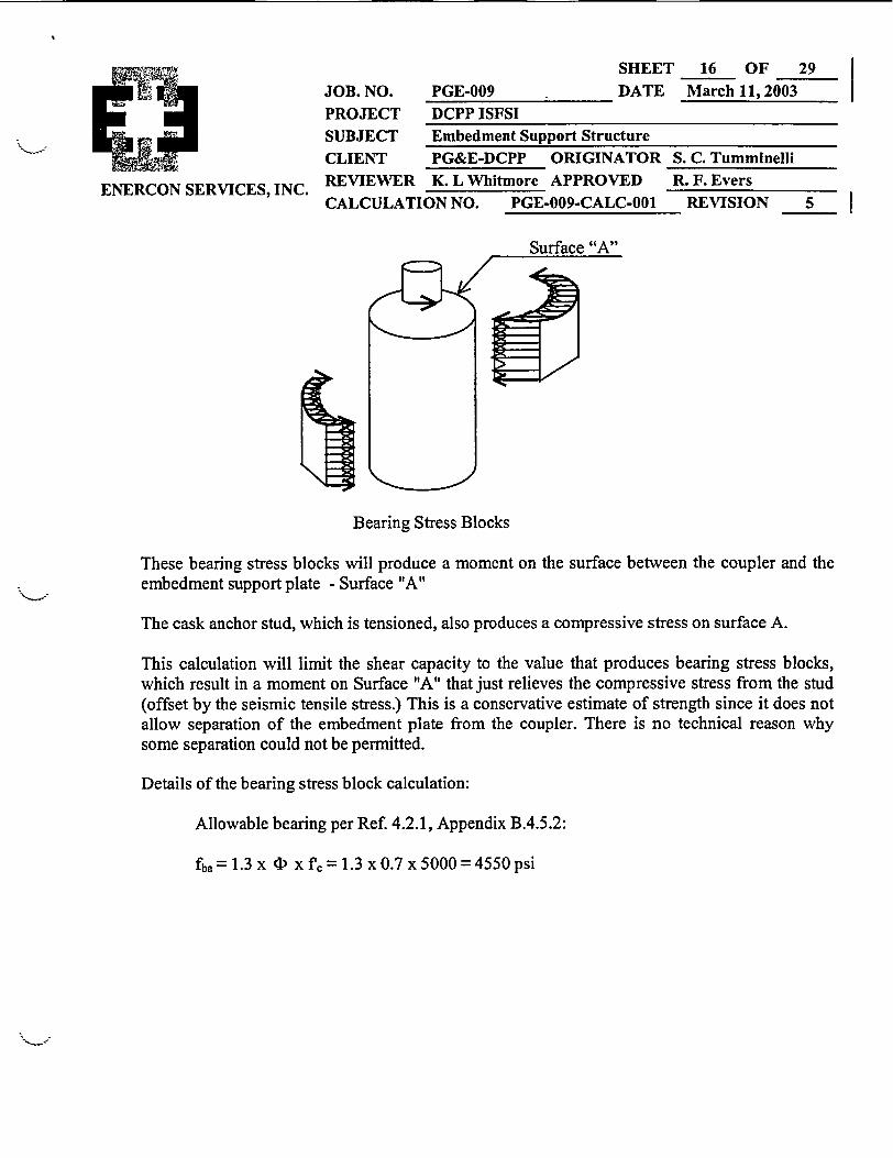
Surface "A"
Bearing Stress Blocks
These bearing stress blocks will produce a moment on the surface between the coupler and theembedment support plate - Surface "A"
The cask anchor stud, which is tensioned, also produces a compressive stress on surface A.
This calculation will limit the shear capacity to the value that produces bearing stress blocks,which result in a moment on Surface "A" that just relieves the compressive stress from the stud(offset by the seismic tensile stress.) This is a conservative estimate of strength since it does notallow separation of the embedment plate from the coupler. There is no technical reason whysome separation could not be permitted.
Details of the bearing stress block calculation:
Allowable bearing per Ref. 4.2.1, Appendix B.4.5.2:
fba = 1.3 x 4) x fc = 1.3 x 0.7 x 5000 = 4550 psi
SHEET 17 OF 29 |
JOB. NO. PGE-009 DATE March 11, 2003 |
PROJECT DCPP ISFSI
SUBJECT Embedment Support Structure
CLIENT PG&E-DCPP ORIGINATOR S. C. Tumminelli
REVIEWER K. L Whitmore APPROVED R. F. Evers
CALCULATION NO. PGE-009-CALC-001 REVISION 5 |ENERCON SERVICES, INC.
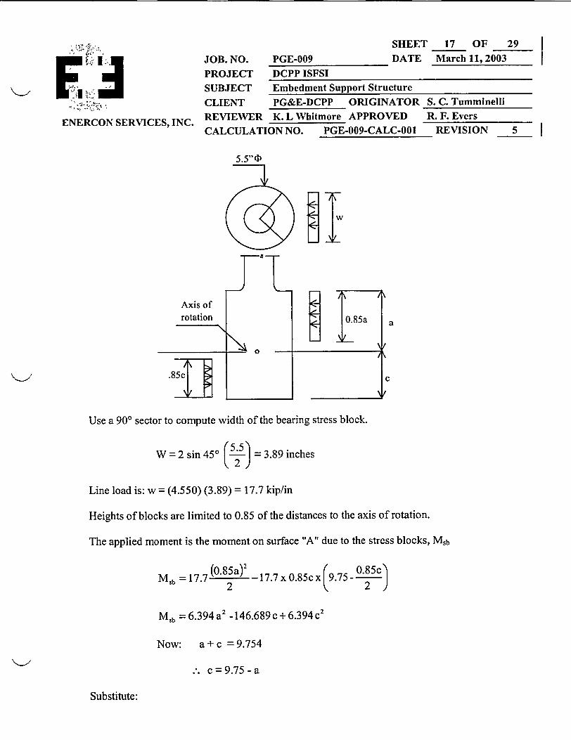
55" c1
NeIw_-r
a
Use a 900 sector to compute width of the bearing stress block.
W =2 sin 450 5.5) =3.89 inches
Line load is: w = (4.550) (3.99) = 17.7 kip/in
Heights of blocks are limited to 0.85 of the distances to the axis of rotation.
The applied moment is the moment on surface "A" due to the stress blocks, Msb
Msb =17.7 (o. 85a)_ 17.7 x 0.85c x 9 .75c- 2)
Msb =6.394 a2 -146.689c+6.394c 2
Now: a+ c = 9.754
.-. c=9.75-a
Substitute:

SHEET
JOB. NO. PGE-009 DATE
PROJECT DCPP ISFSI
SUBJECT Embedment Support StructureCLIENT PG&E-DCPP ORIGINATOR SREVIEWER K. L Whitmore APPROVED f
CALCULATION NO. PGE-009-CALC-001
18 OF 29 l
March 11, 2003 |
S. C. TumminelliL. F. EversREVISION 5
ENERCON SERVICES, INC.
Msb= 6.394a2 - 146.698 (9.75 - a) + 6.394 (9.75 - a)2
Msb = 6.394a2 -1430.22 +146.689a + 6.394(95.063 -19.5a +a 2 )
Mb = 6.394a2 -1430.22 + 146.689a + 607.83- 124.683a + 6.394a 2
Msb = 12.788a2 + 22.006a - 822.39
The allowable moment is computed from the compressive stresses on surface "A".
Compressive force due to preload is 157 kip (Section 2.2).
Maximum seismic load is 62.13 kip (Section 2.2)
Area of A = [5.52- (3.625 + 2 x 0.25)2] = 10.39 in2 , accounting for the 1/4 inch4
chamfer in the embedment support plate.
. (pressure on A) = 157-62.13 9.13ksi10.39
Section modulus of A is:
_ Ic
n I= =5. = 30.71 in4
S = 7= 11.16in'2.75
.-. Allowable moment on surface "A" due to the bearing blocks:
Mall = (9.13) (11.16) = 101.89 in-kip
Set the applied moment equal to the allowable moment:
.-. Msb = Mall
SHEET 19 OF 29
DATE March 11, 2003JOB. NO.
PROJECTPGE-009
DCPP ISFSISUBJECT Embedment Support Structure
ICLIENT PG&E-DCPP ORIGINATOR
ENERCON SERVICES, INC. REVIEWER K. L Whitmore APPROVEDCALCULATION NO. PGE-009-CALC-001
S. C. TumminelliR. F. Evers
REVISION 5 Il~
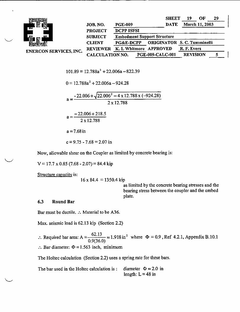
101.89 = 12.788a2 +22.006a-822.39
0 = 12.788a2 + 22.006a - 924.28
- 22.006 + 122.0062 - 4 x 12.788 x (-924.28)
2 x 12.788
a-22.006+218.5
2 x 12.788
a =7.68in
c = 9.75 - 7.68 = 2.07 in
Now, allowable shear on the Coupler as limited by concrete bearing is:
V = 17.7 x 0.85 (7.68 - 2.07) = 84.4 kip
Structure capacity is:16 x 84.4 = 1350.4 kip
as limited by the concrete bearing stresses and thebearing stress between the coupler and the embedplate.
6.3 Round Bar
Bar must be ductile. .-. Material to be A36.
Max. seismic load is 62.13 kip (Section 2.2)
62.13.-. Required bar area: A = 0_____ = 1. 918 in2 where 4 = 0.9, Ref 4.2. 1, Appendix B. 1 0.1
0.9(36.0)
.-. Bar diameter: 4D = 1.563 inch, minimum
The Holtec calculation (Section 2.2) uses a spring rate for these bars.
The bar used in the Holtec calculation is: diameter cD = 2.0 inlength: L = 48 in

SHEET
JOB. NO. PGE-009 DATEPROJECT DCPP ISFSISUBJECT Embedment Support Structure
CLIENT PG&E-DCPP ORIGINATOR SREVIEWER K. L Whitmore APPROVED RCALCULATION NO. PGE-009-CALC-001
20 OF 29
March 11, 2003 I
. C. TumminelliR. F. EversREVISION 5
ENERCON SERVICES, INC. I
(7 t2 2 9 0 0 0 0 0 0
48Stiffness of the bar: k = 1.898x10⁶ lb/in
Any bar used must be faithful to this stiffness.
The pad is sized to have 7 1/2 foot minimum thickness. (It is 7 feet 11 3/4 inch at its thickest point.)The bars must deliver the loads deeply into the pad in order to preclude concrete tensile stressesthat might split the concrete.
Try a 2Y/2 'tDbar, 71.13 (82.88 - 2 - 9.75) inches long from the bottom of the coupler to the topof the anchor plate (Figures 2 and 3).
Coupler is 5½2" D with 2¼/2" 4 hole in it. It is 9 3/4" long.
. Acol = (5.52 - 2.52) = 18.85 in2
4
AE 18.85x29xl06 -5.0 10 6 lbiL 9.75
Aba = (2.5) = 4.909 in24
k AE= 4909X29xlO = 2.001x10⁶ lb/in.L 71.13
Net k:
1 1 1_= k +k kcoriet. kbar
1 1 1_= +
k 56.07x10 6 2.001x10⁶
.-. k = 1.932 x 10⁶ lb/in
The net k is within 1.8 % of the Holtec value and the net frequency is within 0.9 %, thereforeacceptable.
Determination of the bar ductility. Investigate the need for the upset ends:
SHEETJOB. NO. PGE-009 DATEPROJECT DCPP ISFSISUBJECT Embedment Support StructureCLIENT PG&E-DCPP ORIGINATOR SREVIEWER K. L Whitmore APPROVEDCALCULATION NO. PGE-009-CALC-001
21 OF 29March 11, 2003
S. C. TumminelliR. F. EversREVISION 5
ENERCON SERVICES, INC.
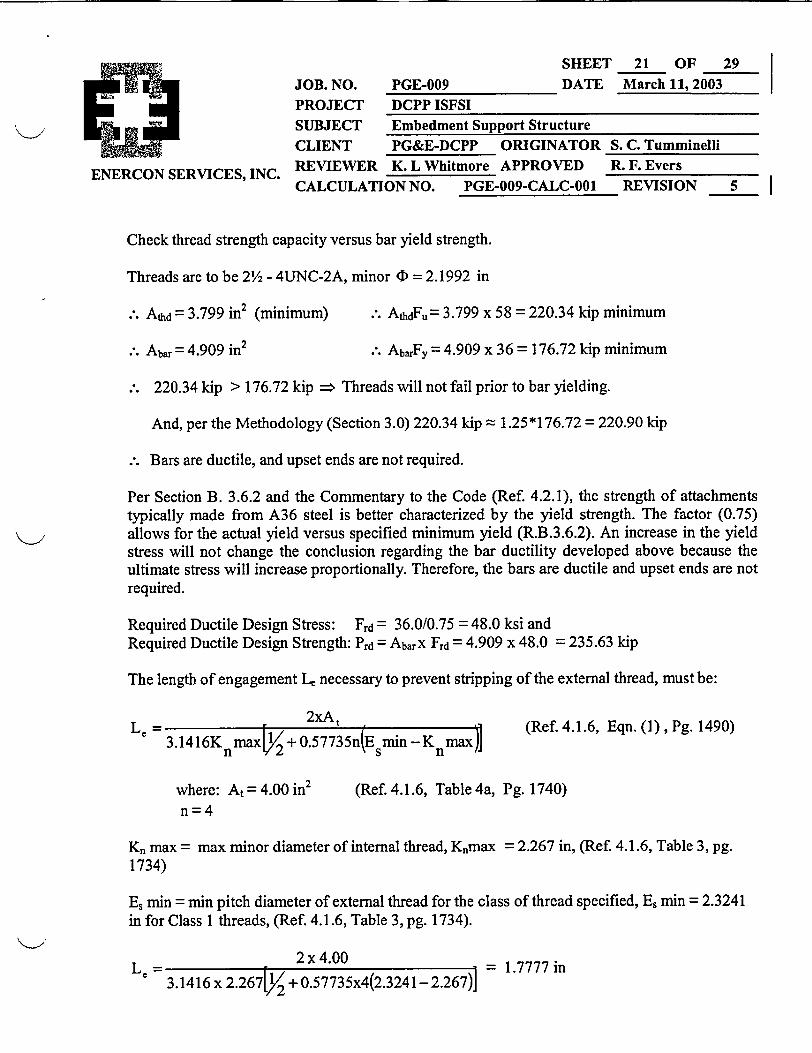
Check thread strength capacity versus bar yield strength.
Threads are to be 2Y2 - 4UNC-2A, minor CI = 2.1992 in
.-. Athd = 3.799 in2 (minimum)
.-. Abar = 4.909 in2
.: AthdFu= 3.799 x 58 = 220.34 kip minimum
.: AbarFy = 4.909 x 36 = 176.72 kip minimum
220.34 kip > 176.72 kip => Threads will not fail prior to bar yielding.
And, per the Methodology (Section 3.0) 220.34 kip = 1.25*176.72 = 220.90 kip
Bars are ductile, and upset ends are not required.
Per Section B. 3.6.2 and the Commentary to the Code (Ref 4.2.1), the strength of attachmentstypically made from A36 steel is better characterized by the yield strength. The factor (0.75)allows for the actual yield versus specified minimum yield (R.B.3.6.2). An increase in the yieldstress will not change the conclusion regarding the bar ductility developed above because theultimate stress will increase proportionally. Therefore, the bars are ductile and upset ends are notrequired.
Required Ductile Design Stress: Frd = 36.0/0.75 = 48.0 ksi andRequired Ductile Design Strength: Prd = AbarX Frd = 4.909 x 48.0 = 235.63 kip
The length of engagement L, necessary to prevent stripping of the external thread, must be:
3.1416K nmax V+ 057 735n(Esmin -Knmax)](Ref. 4.1.6, Eqn. (1), Pg. 1490)
where: At= 4.00 in2
n=4(Ref. 4.1.6, Table 4a, Pg. 1740)
K, max = max minor diameter of internal thread, Knmax = 2.267 in, (Ref. 4.1.6, Table 3, pg.1734)
Es min = min pitch diameter of external thread for the class of thread specified, Es min = 2.3241in for Class 1 threads, (Ref. 4.1.6, Table 3, pg. 1734).
Le = 3F46x 1 2x4.00 23.1416 x 2.2671V + 0.57735x4(2.3241-2.267)]
= 1.7777 in
SHEE'T 22 OF 29
March 11, 2003JOB. NO. PGE-009 DATE
PROJECT DCPP ISFSI
SUBJECT Embedment Support Structure
CLIENT PG&E-DCPP ORIGINATOR
ENERCON SERVICES, INC. REVIEWER K. L Whitmore APPROVEDCALCULATION NO. PGE-009-CALC-001
S. C. Tumminelli
R. F. EversREVISION 5
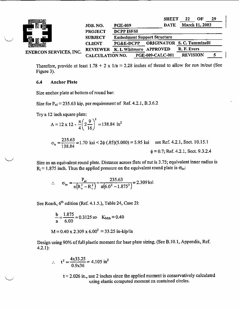
Therefore, provide at least 1.78 + 2 x 1/n = 2.28 inches of thread to allow for run in/out (SeeFigure 3).
6.4 Anchor Plate
Size anchor plate at bottom of round bar:
Size for Prd = 235.63 kip, per requirement of Ref. 4.2.1, B.3.6.2
Try a 12 inch square plate:I' 9\2
A=12x12- 4(2 2- =138.84 in24 ',16)
Cyb =235.63 =1.70 ksi < 2) (.85)(5.000) = 5.95 ksi see Ref. 4.2.1, Sect. 10.15.1138.844 = 0.7; Ref. 4.2.1, Sect. 9.3.2.4
Size as an equivalent round plate. Distance across flats of nut is 3.75; equivalent inner radius isRi = 1.875 inch. Thus the applied pressure on the equivalent round plate is abc:
_____P.d 235.63 =2.309ksi
be (R' - R,2) =76.02 - 1.8752)
See Roark, 6h edition (Ref. 4.1.5.), Table 24, Case 21:
b 1.875- = = 0.3125 > Kjb = 0.4 0a 6.00
M = 0.40 x 2.309 x 6.002 = 33.25 in-kip/in
Design using 90% of full plastic moment for base plate sizing, (See B.10.1, Appendix, Ref.4.2.1):
t2 = 4x33.25 = 4.105 in2
0.9x36
t = 2.026 in., use 2 inches since the applied moment is conservatively calculatedusing elastic computed moment on contained circles.

SHEE'rT 23 OF 29March 11, 2003JOB. NO. PGE-009 DATE
PROJECT DCPP ISFSISUBJECT Embedment Support Structure
CLIENT PG&E-DCPP ORIGINATOR
ENERCON SERVICES, INC. REVIEWER K. L Whitmore APPROVEDCALCULATION NO. PGE-009-CALC-001
S. C. TumminelliR. F. Evers
REVISION 5 I
�� ISUMMARY of shear capacities (Applied shear is 515 kip, section 2.2):
1) Embedment support plate shear capacity is2) Coupler: Bending capacity of the boss:
Shear capacity of the boss:Concrete bearing capacity:
4176 kip4854.4 kip1227.2 kip1350.4 kip
> 515 kip> 515 kip> 515 kip> 515 kip
The round bars are also adequate for the applied loads, have the appropriate stiffness, they areductile, and meet the ductility requirements of Reference 4.2.1 (Section B.3.6.2).
Therefore, the embedment hardware has sufficient capacity to withstand the loads defined byRef. 4.1.4 imposed due to the seismic events.
This calculation, to this point, has qualified the embedment support structure for the appliedloads and has determined that the round bars are ductile. The direct tensile load path, through thecoupler to the anchor plates, including the concrete bearing stresses will not fail prior to therequired ductile design strength of the round bar at a tensile load of 235.63 kip.
6.5 Nuts and Bolts
The assembly of the structure is to be performed with the goal of minimizing gaps in thoseportions of the structure that deliver the loads to the concrete.
The 2 l/2 inch round bars are to be installed so that they bottom out on the diaphragm in thecoupler between the 2 inch and 2 1/2 inch holes. Then they are torqued hand tight. This mates thethreads between the rod and the coupler to deliver the tensile loads to the concrete without firstremoving the gaps between the threads.
The anchor plates are to be attached to the rods with standard hex nuts and jam nuts. The jamnuts are specified to prevent any loosening of the joint prior to concrete placement. Two sets oftorques/tensions are provided for installation. One is a lower set that is designed to just seat theparts without any significant stress. This requires the jam nuts. The other set produces thestresses in the pieces that would be used if this were a structural joint, say in building structure.This produces some significant stress in the pieces. In this case the jam nuts are not requiredsince the higher torque is sufficient to prevent any loosening of the joint prior to concreteplacement.
The nuts are to be standard heavy hex A536 Grade A nuts for use with the A36 steel, withstandard F436 type 1 circular washers.
Further, assembly bolts to hold the couplers in place are to be A307 bolts, to be used withoversize -washers.

SHEET 24 OF 29March 11, 2003 |JOB. NO. PGE-009 DATE
PROJECT DCPP ISFSISUBJECT Embedment Support StructureCLIENT PG&E-DCPP ORIGINATOR S
ENERCON SERVICES, INC. REVIEWER K. L Whitmore APPROVED RCALCULATION NO. PGE-009-CALC-001
. C. TumminelliR. F. EversREVISION 5 I
�� IThe maximum torques specified are from Ref. 4.1.7, Table H, which provides torque values forunlubricated threads (nut factor 0.2) and stresses the bolts to 50% of their yield strength.
6.6 Embedment Support Structure Ductility Evaluation/Requirements for the Pad
The following calculation evaluates the pad to ensure that the embedment support structure/casksupport pad system will not fail prior to the round bar required ductile design strength of 235.63kip.
The bar force is Prd = 235.63 kip
The Neutral Axis XNA is shown in its approximate location in the Figure on the next page. It does139.5
not have to be located since the maximum value of XNA is = 69.75" because it must lie2
beneath the footprint of the cask.
The d value for the pad is (see Figures 5 and 6):
d = 9.75 + 71.13 - 2.815 - 1.27 - 0.815 - 1.27/2= 75.345 in
Now bars 5, 6, 7 and 8 are all within 75.345 inches of the Neutral Axis (see Figure 4) Therefore,the load delivered upward by the anchor plates will all be reacted by the downward force of thecompression zone as a compression strut within the concrete.
Hence, only the forces contributed by bars 1, 2, 3 and 4 will produce net shear in the pad crosssection. Assume all of the bars are at Prd.

SHEE'r 25 OF 29
March 11, 2003JOB. NO. PGE-009 DATEPROJECT DCPP ISFSISUBJECT Embedment Support StructureCLIENT PG&E-DCPP ORIGINATOR
ENERCON SERVICES, INC. REVIEWER K. L Whitmore APPROVEDCALCULATION NO. PGE-009-CALC-001
S. C. TumminelliR. F. Evers
REVISION 5 I
I
BAR CIRCLE4
Figure 4Plan Geometry of the Cask Anchor Studs
(Also, see Figure 1)
SHEET 26 OF 29
JOB. NO. PGE-009 DATE March 11, 2003
PROJECT DCPP ISFSISUBJECT Embedment Support Structure
CLIENT PG&E-DCPP ORIGINATOR S. C. Tumminelli
ENERCON SERVICES, INC. REVIEWER K. L Whitmore APPROVED R. F. EversCALCULATION NO. PGE-009-CALC-001 REVISION 5
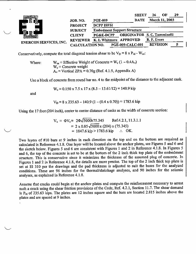
Conservatively, compute the total diagonal tension shear to be VD = 8 x Prd - Wc,:
Where: Wce = Effective Weight of Concrete = We (1 - 0.4Av)Wc= Concrete weightAv =Vertical ZPA = 0.70g (Ref. 4.1.9, Appendix A)
Use a block of concrete from round bar no. 4 to the midpoint of the distance to the adjacent cask.
W= 0.150 x 7.5 x 17 x (8.5 - 13.61/12) = 140.9 kipand
VD = 8 x 235.63 - 140.9 (1 - (0.4 x 0.70)) = 1783.6 kip
Using the 17 foot (204 inch), center to center distance of casks as the width of concrete section:
Vu = <DVc= 20F 6b75.345 Ref.4.2.1,11.3.1.1
= 2 x 0.85 -jf5OOx (204) x (75.345)= 1847.6kip>1783.6kip .-. OK.
Two layers of #10 bars at 9 inches in each direction on the top and on the bottom are required as
calculated in Reference 4.1.8. One layer will be located above the anchor plates, see Figures 5 and 6 and
the sketch below. Figures 5 and 6 are consistent with Figures 1 and 2 in Reference 4.1.8. In Figures 5
and 6, the top of the concrete is set to be at the bottom of the 2 inch thick top plate of the embedmentstructure. This is conservative since it minimizes the thickness of the assumed plug of concrete. In
Figures 1 and 2 in Reference 4.1.8, the details are more precise. The top of the 2 inch thick top plate is
set at El 310 per the drawings and the pad thickness is adjusted to suit the bases for the analyzedconditions. These are 96 inches for the thermal/shrinkage analyses, and 90 inches for the seismicanalyses, as explained in Reference 4.1.8.
Assume that cracks could begin at the anchor plates and compute the reinforcement necessary to arrest
such a crack using the shear friction provisions of the Code, Ref. 4.2.1, Section 11.7. The shear demand
is Prd of 235.63 kips. The plates are 12 inches square and the bars are located 2.815 inches above the
plates and are spaced at 9 inches.
SHEET 27 OF 29DATE March 11, 2003JOB. NO.
PROJECTSUBJECT
PGE-009DCPP ISFSIEmbedment Support Structure
CLIENT PG&E-DCPP ORIGINATOR S. C. TumminelliREVIEWER K. L Whitmore APPROVED R. F. EversCALCULATION NO. PGE-009-CALC-001 REVISION 5
ENERCON SERVICES, INC. II
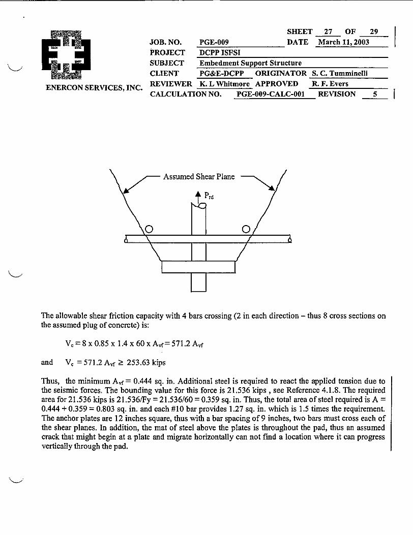
The allowable shear friction capacity with 4 bars crossing (2 in each direction - thus 8 cross sections onthe assumed plug of concrete) is:
V =8x0.85x 1.4x60xAf= 571.2 Avf
and V, = 571.2 Avf 2 253.63 kips
Thus, the minimum Avf = 0.444 sq. in. Additional steel is required to react the applied tension due tothe seismic forces. The bounding value for this force is 21.536 kips , see Reference 4.1.8. The requiredarea for 21.536 kips is 21.536/Fy = 21.536/60 = 0.359 sq. in. Thus, the total area of steel required is A =0.444 + 0.359 = 0.803 sq. in. and each #10 bar provides 1.27 sq. in. which is 1.5 times the requirement.The anchor plates are 12 inches square, thus with a bar spacing of 9 inches, two bars must cross each ofthe shear planes. In addition, the mat of steel above the plates is throughout the pad, thus an assumedcrack that might begin at a plate and migrate horizontally can not find a location where it can progressvertically through the pad.
SHEET 28 OF 29DATE March 11, 2003 |JOB. NO. PGE-0I
PROJECT DCPP]SUBJECT EmbedCLIENT PG&E-REVIEWER K. L WCALCULATION NO.
09
ISFSIment Support Structure
.
-DCPP ORIGINATOR S,Thitmore APPROVED 1
PGE-009-CALC-001
. C. TumminelliF F. Evers
ENERCON SERVICES, INC.REVISION 5s
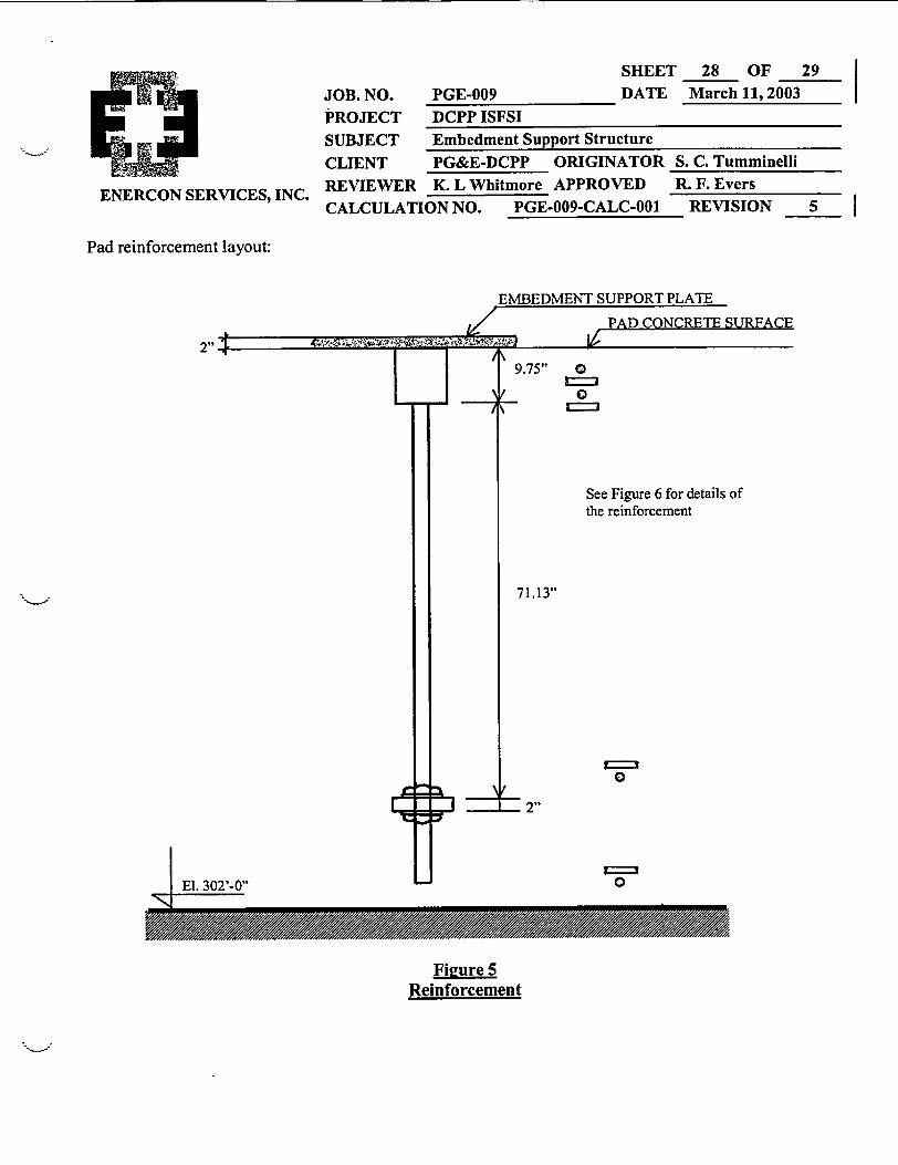
Pad reinforcement layout:
EMBEDMENT SUPPORT PLATE
V PAD CONCRETE SURFACEIt414:1~t 0 XA*1--V
LY
1+--T\
9.75" 0
0&___/
See Figure 6 for details ofthe reinforcement
71.13"
0
- 2"
El. 302'-O C=
Figure 5Reinforcement

SHEET 29 OF 29DATE March 11, 2003JOB. NO. PGE-O(
PROJECT DCPP ISUBJECT EmbediCLIENT PG&E-REVIEWER K. L WCALCULATION NO.
09..
'SFSInent Support StructureDCPP ORIGINATOR Shitmore APPROVED
PGE-009-CALC-001
. C. TumminelliI F. Evers
ENERCON SERVICES, INC.REVISION 51
Min. Top of Concrete_ A _
IA Ik- 2.815"
, _
3 ,-S~ ; '
-0.815"1.27"
-0.815"-1.27"- 0.815"- 1.27"
10.34"
,- . . .
80.88"
Short Directionn einforcement
8 ' ,4Long Direction _pReinforcement
l 'a 1.27",:- 0.815"
1.27"
2.815"
d0
d
9-
Anchor Plate
I
. _ 1
C 'V
10- 1.27"_ 0.815"L- 1.27"- 2.815"s Bottom of Concrete
Figure 6Details of Reinforcement
\._j Thus, ductile failure mode of the embedment support structure is assured and the ductility requirementsof ACI- 349, Ref. 4.2.1 have been satisfied.

Sheet 1 of 3I!E ENERCON
SERVICES, INC. Appendix DOC-1 to Calculation PGE-009-CALC-001
OriginatorDate June_27,_2001Reissued November 21, 2001
Appendix DOC-1
This Appendix presents the two sketches that provide the structure and details of the EmbedmentSupport Structure. They are:
Sketch No. PGE-009-SK-301, Sh. 1, "Embedment Support Structure, Diablo Canyon Power Plant",Revision 0, dated 6/27/01.
Sketch No. PGE-009-SK-302, Sh. 1, "Embedment Support Structure Details, Diablo Canyon PowerPlant", Revision 0, dated 6/27/01.

Sheet 1 of 33ENERCONSERVICES, INC. Appendix DOC-2 to Calculation PGE-009-CALC-001
Originator 2Date ___ 27,_2001Reissued November 21, 2001
Appendix DOC-2
This Appendix presents the DRAFT of Appendix B (dated 10/01/00) to ACI 349-00. It is provided inthe following 32 pages, which are paginated in the lower left and right corners as 349-1 to 349-32.
Draft IOJO 1100
\,ode ReqUirements for Nuclear Safety Related Concrete
Structures (/\CI 349-00) and Commentary (ACI 349R-OO)"
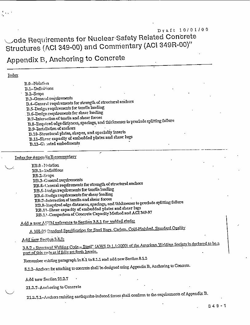
Appendix B, Anchoring to Concrete
Index
3B.0 -Notatiin33.1- Defluil ions
* 32-Scope,1 31-Genertl requirementsB.4-General requirements for strength of structural anchors
3B35-DesIgn requirements for tensile loading
B.6-Design requirements for shear loading
B.7-Interaction of tensile and shear forces
B3-IRequred edge distances, spacings, and thilckesses to preclude splitting failure
B.9-Installation or anchorsB.1.0Structuralplates, shapes, and specialty iserts
B .11-hear capacity of embedded plates and shear lugs
B.122- iuted enmbedments
- Index for Afunluct B-ef ntav
s B.0 4O tation'RB.1- DefwltlousnBB2S-opeRB 3-Gclneral reqreentsI A-( enerai reqtdtements for strength of structural anchors
B35-A ),slgar equkements for tensile loadin g
PM.6- lesigarequiremnts for shear loading
3B.7-tinteraction of tensile and shear forces
RB.9-Required edge distances, spacings, and Thcknesses to preclude splitting fallure
3RB.11--Shear capacity of embedded plates and shear lugs
RB.1 3 -Compariso o£ Concrete Capacity Method and ACTI349-97
Add a new A .r'hreference to Sectlon 3.8.1 for welded studs:
A 108-9!) iThuuiard Specicatio for See Bars. Cain. Cold-Finished. Standard Oaalitv
Acld fiew Section 3.8.7:
3.8.7 - Strutcwral Weldinu Code- Steel" (AW'S .l.l:2000) of the Arnerian "WeldinR Societvis dcl ared to teba
Part of thIs c(.e as -if Fiull set forth merhi,
Renuniber exdsting paragraph In 8.1 to 8.11 and add new Section 8.1.2
8.12-AnchMx-, foc attadiing to concrete shall ber designed usinig Appendix B, Ancdhorag to Concrete.
Add new Section 212.7
21.2.7-Anclioring to Concrete
21.2.7.1-Anchors resisting cartbqguAc-Induced forces shall conform to the requirements of Appedim B.
34 9 -1

Draft 10/0 1100
Appendix B. Anchoring to Concrete
B.O -Notation
Ab= = ngarearof thehadofstudoranchorbol0in
A = proj e faire area of one anchor, fo i of strength in tension, when not limited by ege
distanceor sp;;:;ng, asdefinedinB.5.2l, in? SeeFig.RB5.l(a.1
Ax = projected etefaihzre areaof an anchrc or group of anchrs for calclati of strength in. tensioa, as defned
inB5A1, il. Ax shallnotbttaken greater than nAx . JSeefig.1RB5.B](b
= effective acrs-sectioal area of anchor, in?
Ax = effective cross-secional area of expansioa or undercut anoc hsleeve, if sleeve is within shear plane, inm
Ay4b = projected cracrete failure area of oae anchor, for calclation of strength in shear, vihen not limited by cocner
-icfu p aAm'o" B 6291. h 2 l(e&Vg 5.611(a)
Ay projectL cnaaetefailure aeaofananchor or group ofanchecs, for c1lcati aooftsregeigfin ear, as dned in
B.62Jdiii Av shaflnotbatakengreater thannLAvy. JSee-Rg.RB.62(b4)
C = the comnpressive resultant frce betmen the embedment and the concrete reslting from factored mometat and
factored axia. load applied to the embedmenti
c = distanre fomn center of an aMchor haft to the edge of concrete, in.
c = distanc.u from the center of an anchoc shaft to the edge of colcrete in one dirction, in.; W.aier. shear fcxce is |
applietd to amcho, cL is in the. direction of bie she& fcr [SeFig. RlB.62(a)l
CZ = distance fmmcenter of an anchoc shaft t the edge of cmoce m the directioa octhogonal to c. in.
= thelargesttefie-edge disanes-e eq , in. ( A y - Lf- |
=, the srnalleste o'E dgedltnz di t an r~l hn crajat _ V ,in .i
d4 = outsidc diameter of anicoc oc shaft diameter ofheadedstud, orheadedndifx-bolt in.
ell = nctricity o£nocmyna ocef on a group of anchors; th distancebettw c theresultant tension load oa a group of
anchors in tension and the centroid of the& a-x of gwp of anchors loaded in tension, in.; -e is always
pos i t~v, SeeFig.B5.5.2(b and *)|
ey'= eccntricity of shear force o a group of anchms; the dist&bctbeen thepoint of shear foce application and
the ttntroid of the group of anchors resissing shear in fhc Gdiion of the applied shear, in.
£, specified comprssive strength of concrete, psi;
3 4 9 - 2

Draft 1 /01 1/00
f"-= specified tcsi' s .trength of Cccrde, psi:-
mr = iodulusofim ,;we -ofcccretepsd(Sce9.S.-3 )
f, = calculated ten: i stress in a region of a membxr, psi-.
specified yield t trength of anchoc steel, psi-
f, = specified tenw.1k strength ofarnchrsteel, ps:-
= soecifie6 t ,:'e strength of arnchor sleve, psi-.
h = thickness of ernber in which an anchor is anchoed, measured parallel to anchor axis, in.
hD= efective. anm hOc embedment depth, in. (SceeB.85 and~ig. B:B1)
k = coefladent f ltsaicconcretebreakoutstreagthin tensionr|
lc = coefficient f prout strength:
o= acd-beariLi length of anchoc for shear, not to excxed Sdo in.
bI-foC-Md Lhnsta t nver s full lea of the cmbedded sectioo, such as headed studs oc
ost-mistAlled anchocs vth onee tubular shdl over the full length of the embedment depth-
2id. fo tivy-c-trolled expansica anchocs with a distancesl-eeve s teftdofi the expansion sleevo-
n = number o, achors n a group:
Nb = basiccon- rtebreakoutstrength in teusio ofasingleanchoc in a ed concrete, as def.fdinB522, 1b-
N.n, = nomrnalt creteixeakout strength i tension of a single anchoc, as defined inB52.1, IT
Na, = nomina1 n1cretetceakout strength i tensionofa group of anchos as defined inB.59-l, Tbh
N. = noniinz l 'trcngth in tension, lb:I
N. = ullout . ccnpm taasion of a single anchoc mceac ooacrete, as definedinB53.4,Tl|
Np, = ncaninql pullort strength ntensionofasingleanchoc,as MfinediB53.1,l: -
N~b = sidb-f' l .blowout strength of a single anchor, I-.
Nb s = eidef.i' rblowoutstrengthofagroupofanchorslb
N, = nocnin. I strength in tension of a single anchoc or group of anchors as governed by the steel strength, as defined
in B ' 1.1 oc B5.12, lb:
N. factr d-t! tensileload, lb.1
Ps an= f .,ntedrextoenaltael loadc na.z- mbedne, 1Eb|
s = ancll---center-to-tcnt rspaing,i.
3 4 9 - 3

Draft 10/0 1/00
s. = spacingfg oE the cai nchors aloag the edge in a group, in.
t = thidsessoE wa-ejx r ocplate7 inl
Yb = basic concrete b- .:Aout strength in shear of a single anchoc in cracked concrete, as defned in B.6.2.2 oc B.6.2.3, nA
,b= nominal coxcet .bcea'kout strength in shear oE a single anchor, as defined inB.6.2-1, 1b
Vbt = nominal concrete bxeakout strenglh in shear of a group of anchocs, as defined in B.62Q, lb -
V,? = nominal coacrete pryut strength, as defined in B.63, Ib:
V. = nominal shear strength, lb'-|
V. = nominal strength in shear of a single anchoor c group of anhors as governed by the stel strength, as defined in
B.6.1.1 or B.6.l1.2, lb:|
V, factoredshea, load4lbI
4 = strengthred, 'tionfactoc(5=BA4. 4):
TW = modification A=to, Foc strength in tensio-, to a oMnt for a tfc VOlP
BS k
= modificatiox fcor, foc strength in tension, to account for edge distances smaler than 15he, as &fined in
B52S!5
3 = modificatk' factor, for strength in tension, to acomnt for cradnZ, as defined inB5:;.6 andB5Z7;.
' 4 = modifcatioC factocr foc pullout strength, to accountfocramclng, as definedinB53.1 andBS35.
S modification fac, foc strength in shear, to acmunt fo anchoc groups load c tcally, as defined in
B.625
-c = modificA.iuifactor, f orstengthin shear, to accountfo edgedistances smanlerthlan 1-5c,as definedin B.6).6. |
T.= modification factoc, foc strength in shear, to accmunt focacing, as dfinediB.62.7.
B .1- Defrltdow
Anchor-A steel elenent either cast into concrete oc post-installed into a hardened concrete mnember and used to tansmit
applied loads, including _hmdg dsW boltsu lolzzF bc'Th (I c: L tlO, headed studs, expansion anchos. undercut
anchors, or sMnlY inserts.
Anchor group-A number of anchocs of approximately equal effective embediment depth with each anchoc spaced at less
than three timne- its embedment depth from one or more adjacent anchors.
Anchorpufout strength-Thest ngth ccdsponding to the anchoring d&Ict oc as0cc coxnponent of the devic sliding
outfrom the concrete withoutbxealzing out a substantial portion of the surroumding concrete.
3 4 9 - 4

Dr aft 1O I O 1 1/ 0\.~Chmntn-Th.e StrUCl ,ra ssnbly, eXternal tO the. surfce. of the. cone~teC, that tanlats ltcQds to or reXvs loa frr |
the anchior.
Brittle steel emeneM-An elemaet Aith a tensile test elongation of less than 14 *rgaC e z. *' 2 .itC LtgTlor f
reduction in area o len- than 30 strascenl, ccz h.
Car- r; nnchor-A hefitiled IAt rcbe.aded stud install~ed lfcRrel aline uticrelt-
Concrete breakout strength-The strength corresponding to a volume of concrete surrounding the anchor oc group ofanchors separating frou the member.
Concrete pryott stren k-T13e. strength crresponding to formation of a concrete spall behind a short, stiff anchor with anembedded base ihat i. displaced in the direction. opposite to the. applied shea forme.
Distance sleeve-A S1-zve that ecases the center part of an undercut anchor, a torque-controlled expansion anchor, or adsplacent-control'od expansico anchor, bdt does not expand..
Ductile embedment - An embedment designed for a ductile. steel failure in accordance with B3.6.1.
Ductile steel elementt-An element wit a tensile test elongation of at least 14 * prcent ee n Q in. c leatl+ andfreduction in area of at least 30 4p-ercent. A steel meeting ASTM A.307 shallbe considered ductile. i
-tdge dgts~zacc-.ie. tlo Eeitrfhec . tro the. center of the.nearest anchor.
Effective erredient depith-The overall depth through vbich te. anchoira f cre !f r -the. surromding-- concrete. Ihe. effective embednaent depth will nocmally be. the depth of the cmcrete fallure. surfa in tension
applications. For cast-in headed anclor-bolts and headed studs, the effective embedment depth is measured from thebearing coatact su, face of thehead. (See ig.IB.1)
Embedmernt - A steel compon et embedded in the. concrete to transmit applied loads to or fiom the concrete.structure.. 'Iet embedment may be fabricated of plates, shapes, anchors, reinforcing bars, shear conntctors,secalty insrts, or any combination thereof. .
Expaision aechor-A post-instaled anchor, inserted intohardened coacrete. that transfers lcads into or fhcu the. cccrete|by direct bearing orc fdctioa or boh. Expansioa anchors may be torque-coatrolled, w th. expansion is adileved by atorque acting ci the. screw co bolt, cc dispimcneat-cotrolled, vwhere the expansion is achieved by impact focces actingm a sleeve or rplg and the expansion is controlledby thelength of travel of the sleeve. cT plug.
Expansion sleeve-The. outer part of an expansion anchor that is forced outward by the ceater part, either by appliedtorque cr impacc, to bear against the sides of the predrlled hole.
5 Xp-Ercentf jrctile-A statistical term meaning 90 percent confidence that iter is 95 percent proability of the actualstrength exceeciing the nominal strength. ,Dri -I .ShZ'l in-udz thc nubzr of tz1tz V1t-e cxclting dat t
Wedefd-h lea ed: stud-A steel anchor.& E ee frn :J dravn be tr ztxlc of sa z, h n and. c ld fcx. ad, nrMconforming to the. requirements of AWS D 1.1 e-.eTele affixed to a plate or similar sted attachment by the studarc welding process for ase tsing int- an~1~in ~ rn .ithin ai eM rr ' 7crt.
Post-installetd anchor-An anchor installed in hardened concrete. Expansioa anchors and uandercut anchors are exampleof post-installd archors.
349 -5
Dr aft 10 1.0 11O 0
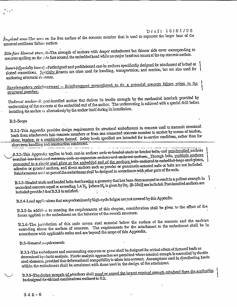
hected area-The are:- on the free surfam of the ccnatt mcmber that is used to rereseflt the larger ba of the
assumed rectilinr failiut Surface.
Side-face blowout strenr,(Jf-the strength of anchocs with deeper embedment but thinner side cover corresponding to
concrete spalling oa the v ;cl face around the embeddedhead vhile no majoc bceakout oCurs at the toQ cocnett surface.
Th-( jpecialty insert) -Predesigned-and-prefcicated cast-in anchors spedfically designed fsc aWacment of bolted fdc
slotted connmeions. c hlty Uinsats are oftmn used for handling, transpotation, and erection, but are also used fcc
anchoring structural ek, nents.
SurLp/emengfrv reilnforcefeft -Rcinforcccnt prcxwirtiorned to tie a mwotim~ial concrete failurc prism to th|
structural mlember
Undercut anchor-A pest-installed anchor that derives its temsile strength by the mechanical interlock provided by
undercutting of the ctxcrete at the embedded end of the anchor. The undercutting is achitved with a special drill before
installing the anchor Cq alternatively by the anchor itself during its installation.
B.2Scope
B2.1-This Appendix provides design requirements foc structural embe1ments in concrete used to.transmitt structural
loads from attacbments into coacrete members cc from cut connected coacrete membr to another by means of tensioa,
sbear, bearing, cc a combinatioa thereof£ Safety levels specified art intended for in-service codifitcis, rather than for
short term, handling and constructioa coadihtons.
22-his Appendx aplies to both cast-in anchocs zuc an chdcc stuSz ze Ieadc Ielt and t acho |
sitsl fl ir~tc etn~crzt, zt-.Th n:, c on cenhefs r. uedffw U ncr. rouT h bolts mltiple anchors |
conneced to a sin l steel late at the emd end of the anchors b eed to emd
adhesive cc groutnd' anchoes, and direct anchors such as powder cc p matic-atuated nails cc bolts are not included.
Reinfoccement us-1 as part ofthe emnbedrant shall be designed in accordance ith other parts of the cixe
B B.2.-laded studs anheaded bolts thath ig a geometry that hasbeen dcsttedtorsultin apullout strength in
uncracked concrete equal cc exceeding l.4A N [vhieeN is giveNbyBq. (B-10a)l areinclude& Post-installed anchocs are
includedprovided thatB33 is satisfied.
B.7-4-oadp applknfions thai arepredonmantlybigh-cycle fatigue are not coverdby this Appendx
B325--In additi 4.0 to meeting the requirements of this chapter, consideration shall be grvm to the effect of the
forces applied to the embedment on the behavior of the overall structure.
B.2.6-The jurisdiction of this code covers steel material below the surface of the concrte and the aachors
extcnding aboyc the surface of coacrete. The requirements for the attachment to thc embedment shall be in
accordance with applicable codes and are beyond the scope of this Appendix.
BZ-General requirexnents
B3.1-The embl-edment and surrounding concrete or grout shall be designed for crtical fects offatoced loads as
determined by dastid analysis. Plastic analysis approaches are permitted wherenominal strength is eontrolledby ductl1e
steel elements, provided that deformational compatibilityis taken into account Assumptions used in distributing loads
within the embedment shall be consistent wvith those used in the design of fthe attachment.
K33.32-T dCin s1rncnzvth of a~nchors shall lqual or crod tclarezo t rcIircd strcnglh callatcd from the appliralulc
l o a d ccnbinations eetEd-in 9.2.
3 4 9 - 6

Draft 10101/00
133-Post-installed structural anchors shall be testedb Ifore use to vrify that they are capablc of sustaining theirdesign strength in cracked concretz under seismic loads. TIhes verification tests shall be cooducitd by anindependent testing agency and shall be certified by a professional engineer with full description and details of thetesting programs, prcscdures, results, and conclusions.
B.3.4-A provisions fPv anchor axial tension and shear strength apply to ncfmalweight concretc only.
1-3-35-The values of f, used for calculations in tis Appendix sball not exceed 10,000 psi for cast-in anchors and 8,000psi for port-installed :.achors.
3z.6-Embedment tlesign
B3.6.1-1mbedment design shall be controlled by the strength of embedment steel. The design strength shall bedetermined using Ome strength reduction factor specified in B.4.4(a). It shall be permitted to assume that design iscontrolled by the strength of embedment steel where the design concrete breakout tensile strength of theembedment, the design side blowout strength of the embedment and the design pullout strength of the anchorsexceed the specified ultimnate tensile strength of the embedment steel and when thc design concrete breakout shearstrength exceeds 65 5percent of the specified ultimate tensile strength of the embedment steel. The design |concrete tensile strength, the design side blow out strength, the design pullout.strength and thc design concretebreakout shear strength shall be taken as 0.85 times the nominal strengths.
33.6.2-As an altternate to 36 . sac ent- e-designed-ol level corresponding tof-or feres -no; greater-thanthe 4 a nchor desi~strength speified in B.4.13. The anchor design |
strength shall l/ iletcrnined using the strength reduction factors specfid in orTW -06c.
B .36-SIt shall bpermitted to design anchors as nonductile anchors. The design strength of such anchors shaUbe taken as 0.(. ' Nl and 0.60 ,hewhee r is given in BAA .a Nd andYV are deermined in acordanc thB.4.1.
B1.3.7-Matri. and testing rquiremets for embedment steel shallbe cfiedby the Engineer so that thcembedment design is compatible with the intended function of the attachment.
B3.89-mbem entzmaterials for ductile anchors other than xeinforcingbars shall be ductile steel elements.
B339-Ductilc anchors that icorporate a reduced section in the tension or shear load path shall satisfy one of thefollowing conditions:a) The ultinuate tensile strength of thereduced secion shallbe greater than the yield strength of the unreduced
section.b) Forbolts, Ihe length of thread in the loadpath shail bat least two anchor diameters.
B3.1-Thc lesign strength of embedment materials may be increased in accordance. with Appendix C forembedmenn. subject to impactiye. and impulsive loads.
fl.3.11-P1astic deformation of the embedment is permitted for impactive and impulsive loading provided thestrength of the embedment is controlled by the strength of the embedment steel as specified in B.3.6.
P.4-Gener .1l requlrements for strength of structural anchors
B.4.1t--SLtrgth design of etwel anchors shall be based dther on the, aczutwdioc ing :s ign models that satisfy the|requiremnits oEB.42 or on test evaluatiom using the Sopcrmnt fractile of test resultsfor the following:
a) steel trength of ancho in tension (.5.1>a
3 4 - 7

Dr aft 1 010 1 /00steel strength of tnchor in shear (B.6.1>,
c) concrete breakout strength of anchor in tension (B.5.2d) concrete breakout strength of anchor in shear (B.6.2);c) pullout strength of anchor in tension (B.5.3> -f) concrete side-face blowout strength of anchor in tension (B.5.4), .g) concrete pryout strength of anchor in shear (B.6.3)t-
In addition, anchors sl ll satisfy he required edge distances, spacings, and thicknesses to preclude splitting failure as
B.4.1.1-For the desi nfn of anchors, except as required in B33,|
> N (B-1)
iV (B-2)
B.4.1.-TIn Eq. (B-1) and (B-2), tND and Y,, are the lowest design strengths determined from all appropriate failuremodes. tN, is the lowest design strength in tension of an anchor or group of anchors as determined from cosideration oftN,, N ither tN., a §N , and either tN,, cc §Nbr RY is the lowest desiga strength in hear of an anchor oc agroup of anchors a determined frm consideration of V.V, either 4Va or fYs, and §,.?
B4.13-Vhen both N, and V,, arepresent, interaction effet shallbe considered in accordance with 1B 3.
TB.4I-ThoinastrngtLuhany anchor oc zgroup of atichors shallbbased on desiga mcels thatresult i preMctions -- -
of strength in substantial agreemcat with results of i7Thm.lersed - dihe -tests hall I--acmpafble ithltmaterials used n the tstructe. Thenoinalstrgfti sallbe dod onthe 5 no4Lnt fractle of thebsic.in(dividual wiidlor strength. Foc nninal strengths related to the crete strength, modifications f size effects, thenurnbr of anchcks, the effects of dlose spng of anchors, proximity to edges, depth of thc cocrete member, cocntricloadings of anchoc groups, and presence or absence of crading shall be accomted fcc. I imts on edge distances andandior spa cig .n thc desiggn nbddls slallb consistent with the tests that erifiedfhtemodes
B.4.21-The effect of supplementary reinforcement provided to counfe OC restrain the concretebreakout, &r both, shall bepermitted to b included in the design models ef-used to snfisRv B.42|
BA2.2-Fx anichocs vAth diameters not exceeding 2 in, and tensile embedmeats not exceoding 25 in. in depth, thecoacrteze=akt &t strength requiremcats e 4halbe cccisidered satisfiedby the design proredure of 135.2 and.B.6:2- |
B.4A-I esistauce to coabined tenhile and shear loads sbaU bbe considered in design using n interaction expression thatresults in comi utation. of strength in substanial agremnet with results of compreiensive tests. 'his requirement shall bccmsidered s~aisraedbyB.7.
B.4.4-Stren th reduction factor t for anchorsirte in concrete shall be as follows when the load combinations of9.2 areused:
a) Anchcc governed by strength of a ductile steel element
i) TensionLoads ........... 0.80ii) SlicarLoads ............ 0.75
'b Anchcr governed by strength of abittle steel element
i) Tension Loads .......... 0.70ii) ShearLoads ............ 0.6S
349 - F;

Dr aft 10/0 1 100
c-Anchor governed by wacrctceakout, side-face blowout, pullout oc prut strengSh 0.75
B.4.5- Bearing Strengtl
13.4.5.1 - A combinatiost of bearing and shear friction mechanisms shall not be used to develop the nominal shear
strength defined in accordance with 9.2-of c oe-'e. If the requiremeats of 9.2.3 are satisfied, however, it is
pemritted to-use the available confining force afforded by the tension anclhorsin combination with acting (or
applied) loads used in determining the shear strength of embedments with shear lugs.
B.4.25 - The design bWaring strength used for concrete or grout placed against shear lugs shaU not exceed 1.3 tC' using a
strength reduction factor 4 of 0.70. For grouted installations, the Nalue of £ ' shall be the compressive strength of the grout
ncc he concrete, whiche er is less.
B35-Desgn requiren. nts for tensileloading
B.5.1-Steel strengtl of anchor In tension
1.5.1.1-lhe noninal strength of an anchor in tension as governed by the sted, N,, shall beR evaluated by calculations
based on the prwert I of the anchor material and the physical dimensions of the anchor.
B .5.121het on-iinal .trength of an anchor & group of anchocs in tension N shall not exceed|
N ~ (B-3)
_ihere f, shall not be taaken greater than 1.9!, oc 125,000 psi.
B 5.2,Concrete bcakout strength of anchor In tenslon
BS.2-.Ih-Thnomi I: l c retc breaout s trgthA-, of an ancor o group of anchors in tension shall not exced
(a) for:' ingle aachoc.
N AN (B-4a)Neb kV' 2 V3Nb
co) for a:group of anchors:
AN (B24b)ilaA -VN. 2 V 3Ni,
. c . iis the projected area |
of the failure surface for the anchor or group of anchors that shal be Mproximiated as the base of the rectilinear
geometrical figprre that results from projeG ng the failure surfce outward 1.5h, from the centerlines of the anchor, oc in
the caseA o£ a ,X cp of anchomn from a line through a rowt of adjacenthanchoe. j shall ioc exc n At6 Vhert n is thc
number of ten siuid anchors in the group. Av is the projected area of the failure surface of a single anchor remote from
edges:
AN,, 9 h2 (B-5)
B I.-2'he "- -. ic ccncretebreakout strength N of a single anchoc in tension in caded onacr='- shall not exceed:
Nb= k47. h'Ci (B-6a)
where 1: - 24 for cast-in lieade&s auad va -e Ismch s
349-9

Draft 1010J100
k = 17 for P1 -:t-installed anchors.
Alteruativedy, foc cast-inl eaded studsandhead boltswith 11 in.<h rh525 in, thetasic cocretezLeakoutstrengdh of a
single anchcc in tensicx',i craked c=acret tshall not exmcee
Nb = 164fh~,5 13 (6)
B.15 9.3-l- the special case of anchos in an application with three or four edges and thelargest edge distance c,,. < 1.5
lid, the embedment depth hllusedinEq. (B-5), B-6), (B-7), and (B-8) shallbelniltedto c.Jl.5.
B.52.4'he, modifat -n factc fcc ecceatrically loaded anchcc groups is:
1-L <1(B-7)ytri +2e'
Eq. B-7) isva~dfb eN C S/2 .
.If the loading on an anchoc group is such that only scme anchors are in tension, odly those anchors that are in tension
shalib coasidered vAien detamining theeccentricity, e , fc= seinEq. (B-7).
In the case where eccentric loadino exists about two axes, the, modification facto, -rl shall be computed. for eacn 05 -
individuallyandhtl Producofthesefaccsused asyLm4 E.(B-4bi).
VI is equal to 1.0 f.- a ductile embedmeat analyzed using oaly linear (elastic) analysis teminiques.
B.55lhe modificatio fctor fcc edge effects is:
V2 = 1if cj,,, >1.5 he
V2=07+03 Sh if c,<1. 5hr (B-8b)
B 6-NWhen. -II anchoc.'is located inma regixod of a coaeze member vwem analysis indicates no crackng
(f< < f) under th, load combinatioas secsed in9 2 vwiih load facts taken as unlity, th following modification factoc
shallbepamattt t i:
1/3=~ 1.25 for cast-in Exnciorsl-ai St1.BaJ'a edo.; nnrG
W-3 = 1.4 for post-installed anchors.
e 4S-,7WhcV -analysss indicates craddng under the load cicnAinatious specified in 9. witih load factors taken as unity, |
NV Shall be tal.en as 1.0 foc both cast-in anchors aiLd post-installed anchocs- TIht craddng in the concrete shall be
controlled by flexuralreinfbccomcnt distributed in accocdance with 10.6.4, oc equivalet cack coutrol shall be provided by
coafining reiriofcement.
B5a.78-Wben additioaal platc(W asher is added at the head oE thc anchoc, it shall bc pemitted to calClJt the |
prcjected area of thc failure sudaombyproecting the failure surface outvd 1.5hfrom. the effect perimeter of theplate
oc washer. Mhe effective pemimeter shall not exceed the aue at a sectio prced outward more than t from te outer
"- edge of thclt .1 of anchor, Wherc t is the thickness ofthtwasher orplat
34 9-1 0

*1
Dr aft 1 0 10 1 /00
- For post-instnlled anchors, it shall be permitted to use a coefficient, k, in equation B{Oa based on the 5
rpcrccnt fractilt of sesults from product-specific tests. For such cases, themodification factor, V3, shall be based Ion a direct conparison 1 ltwe th average ultimate failure loads and the characteristic loads based on the 5
epmcsrnt fractile of product-specific testing in cracked concrete and otherwise identical product-specific testing in |
uncracked concrete.
f.53-uM1out strengtl' of anchor In tension
B53.1-Thtnominal 1 ' illout strength .N2of an anchor in tension shalI not exceed:
pn=Y/4 H p (B-9)
13532-For post-instilled expansion and undercut anchors, it is not permissible to calculate the pullout strength in
tension. Values of NO shall be based on the 5 -Tcrpqcct fractile of results of tests performed and evaluated aoxcding to
B.33.
B1.533-For single cnst-in headed studs and haded bolts, it shallbe, permitted to evaluatc thtpullout strength in tension
using B53.4.
B .53.4-Th pullout \trength in tension of a single headed stud or headedbolt, Ne, for use in Eq. (B-9j, shall not ex-ceed
_ _ _ _ _ _ _ _ _ (B4O a)|
__ -. > ~~ - l-
B3.5-For an aw~clor located in a rtgion of a concrete member where analysis indicates no cracking (f- f,) under
` the load ccmnbinalixis specified in 92 *ith load factors taken as unity, the following modification factor shall be
permitted:
r4 = 1-4
Otherwise, 4 shaJI be taken as 1.0.
B.5.4-Concrete side-face blowout strength o( a headed anchor intension
B.5A.1-Foc a single headed anchoc with deep embedment close to an edge, the nominal side-fam blowout strength Nb
shall not cxoeed
* X,-1 kg,>g(B-11)
if the single andicv is located at a perpeadiailar distance, cz , less than 3c frcon an ede, the vaue of Nl shallbe modified
bmultiplisd.441itby the factc (1 + c2lc)/4 whecr l< c2/c <3.
B-5.42-Foc multplo-headed anchors with dep embedment close to an edge (e < 0.4 Ii and spacing between anchocs
less than 6c, et i nominal strength of the outer anchors along the edge in the gtoup foc a side-face blowout failure NA,
shal not exceed
Nsbz = 1 + 6(B-12)
where SQ = spacing of the outer anchors aloag the edgcin thegroupandNbis obtained fromEq. (B-11) Mithout
modification for a pcpendimlar edge distance. The nominal straegth of the group of fasteners shall be taken as the
- nominal strenyth of the outer fasteners along the cd e multiplied by thc number of rows parallel to the edge.
3 4 9 - 1.
* r a f t 1 0 / 0 1 1 0 0
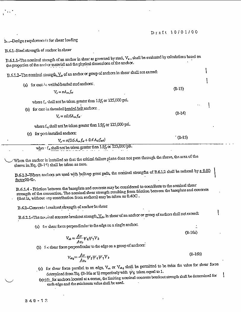
bhDeslgn requlremetit 3 for shear loading
B.6.1-Steel strength of ̂ n chor ln shear
]-.6.tl-The nomiinal strength of an andioc in shear as governed by steel, V, ,shall be evaluated by calauations based on
cthprcperties of the an-1Clr material and thephyslc1 dimenssons of the anchor.
B3.6.12-The noalal .trcagWLYhP of an anchor or group of anchors in shear shallnotexced:|
(a) forcast-,.;ivmelded-headedstudanchors:.
-Y. = nA..f. (B-13)
whaere fX, shailno~tb takenl greater than 1.9f 7 or 125,000 pSiL
(b) fcccast-inth rsn liead--Aboltaarcor:,
Y. = nO.6A,,fa -(B-14)
where £,, shall notbttakm greater than 1.9fy cc 125,000 psi.
(c) foe pct-installed anchocrs:
*V, = d0.6 Af*± 0.4 AjfwO (B-15)
he-if - f., shallnotbe taken greater than 1.9f or 125,000 psi.
K'When the anchor is installed so that th critical failure plane does not pass through the sleeve, the area of the-
slmeve inBq. (B-I') shall be taken as zero.
B.6V1_7-)Vqrq anchlocs are used with built-up grout pads, the norbinal strengths of B.6.12 shall be reduced by a 0,0|
B. .61.4 -Friction between the baseplate andoncretm may be considered to contrbute to the ncminal shear
strength of the connection. The nominal shear strength resulting from fiictioa between the baseplate and concrete
(that is, without ;,ny contribution from anchors) mayb-taken as 0.400.
B .62-Comrete 1 .reakout stregh o[ anchor In shear
B.62.1-The n(?.,nal concretelxakout stensgth.O5 mn shear of an anchor oc group of eniCxos shallnot exceed
(a) ferr shea force perpendicular to the edge oQ a single anchoc.
a =AvhV Vb (B-16a)AvO
Ob fi <shear forceperpenolar to tecedge ona group of ancacas:
b = Av rBb B-16b)Av.
(c) for shear ocrce paral~el to an edge, V6l oc Y,-, shall be pwrmurd to be, twice the, value foc shear f~cmc
determined fromt-q. (B-16a orb) respectvelywith V6 taken eCal to 1.
'.> (e-L) foranhorslocatedataconerthelimitingnominalconcr tea akoutstrengthshallbedeterminedfor
each edge and (he minimum value shall be used
349 -1 ?

Draft 1010 1/00
~-9 he-1is the projeced arta of the filS sufaeo coa the
sideofthooneteflmeiber atits edgefo asinglcanchococ a group ofanchc& Itsh-,lb pnt ,th ==
as thebse oE a wuncatek half pyramid prected c th side fa oEthcmember shcre thettu oE thchalfp)Tamid is givn
by the axis of the andlch row selected as citical Ihe value of c, shall bet taken as the distance from the edge to this axis.
AshallnotexceedniA, haeren is thenumber of anchors in thegroup.
A, is the projected area for a single anchor in a deep member and remote, from edges in the direction pe:padicular to the
shear fcrce. It shal be prnnitted to evaluate this area as the base of a half pyramid with a side length parallel to the edge
of 3c1 and a depth of 1.5 cj:
A,, = 4.5c,2 (B-17)
WYhere anchors are 1(xated at varying distances from the edge and the anchors are welded to the attachment so as to
distribute the force to ail anchors, it shall be pamitted to evaluate the strength based oa the distance to the farthest row of
-anchors from. the, edge. In this case, it shaUl be pewmtttd to base the, value of c, on the distzmm fro m the edge~ to thc axis of
the farthest anchor row vhich6 is selected as critical, and aUl of thc shear shall b assumed to be, carried by this cr~itical
anchor row alam.
B.6.2.2-The basic ciacrete breakout streng bhYV in shear of a single anchor in cradked ciacrete shall not excee&
V 4 4C15d- (B 18a)
B.6.234kx cast-in headed studs% &bed 1b-lts, Nat are rigidly welded to steel attachments haVng a minimum
.thickncss equal to the greater of g in. or half of the anchor dinmetCrl unl dz m cz xin U.TS E 1 the
basic concretebrceal-.out strength.V, in shear of a single anchcr in cracred cocraete sall not exceed
0 2Vb7=f8(--) 4 i c.5 (B-18b)
doprovided that:
a) for groups of anchors, the strength is determinedbased oa the strength of thcrow of anchos frthest cm
the edge.
+t-L) Jic center-to-cater spacing of the anchors is not less than 25 in.
e)-CY s:.p-lernmtaryren-fbcoment is proided at the cocnas if C2 :E 1.5he
B.6.2.4-Fo the speial c of anchors sn a thin mcnbr influencedby three oc more edges, the edge distance c1 used in
Eq. (B-17), (B-1la), (B-19), and (B-20) shaUlbelimitedtohl15.
B.62.5-Tht3r, lificatonfactor foc eccentricallyloaded anchor groups is:
= 2 t 1 (B-l9)
1+ '3 CI
Eq. (B-19) is valid for e' < s2.
B.62.6-The modification factor fo edge effects is:
V- = l if C2 2- 1 (B-20a)
349-1 3
Draft 1 0 1 0100
-' 0.7 + 0.3 1 if C2 < 1. 5 C (B-20b)
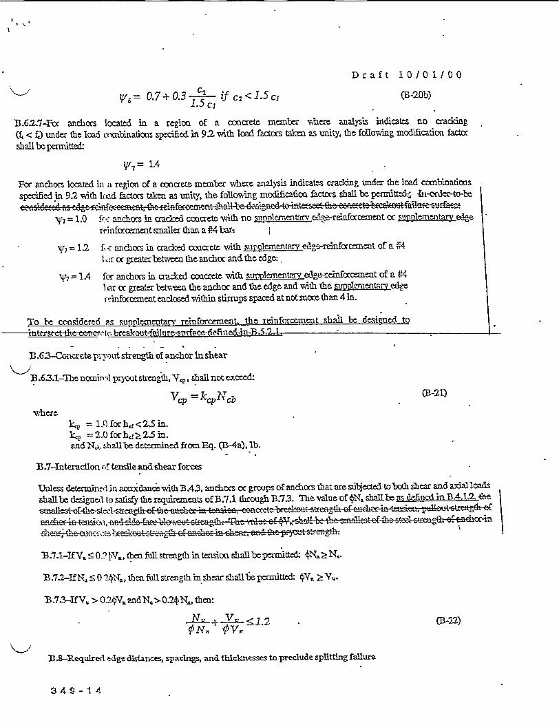
D.6.2.7-For anchors located in a region of a coaete member where analysis indicates no crading(f < f3 under the load corbinations specified in 9.2 with load factors taken as unity, the following modification factorshallbepenitted:
Vf7= 1.4
Fcc anchors located in a region of a concrete nmember where analysis indicates cracldng under the load ccmbinatioosspecified in 9.2 with lxid factors taen as unity, the following modificatioa factrs eball be pitted:: T r-to
cenercdn GS c~rif~ccalnt. thrcinfrcurn'cnt -zha1l 1 ds ^ _cd te intc::e thc. c' Lrczcsv ut e fa~eue -urface.:= 1.0 fc-. anchors in cracked concrete. with no supplnementarv e e-reinfrcenent cc sgnprlementaw oe |
rehnforceaent snller than a #4 ba|
7= 12 fc anchors in cracked cocxrett with siiplcmentM ea--renfcccemeat of a #41 Ur or greaterbetwen theanchoc and thc edge.
7 = 1.4 fo anchors in craced coxcrete with Sppjgnentaty edge-reinforcement of a 14liar cc greater bttweea the anchor and the edge and with the g~plgnetArv edrctnforcement enclosed within stirrups spaced atnotmore than 4 in.
lo te cm'sidered is supplementarvt reinforcement, the -rinforcernct sbha be dmsijed toitt~tel brakee-fheh4efied4Thtl-,- - |
B .63ncrete ,; strength of anchor In shear
B.63.1-Ihe ncnin il pryut strength, Vp, shaUlnot ecee&
V,,p =kp ~Ycb (B-21)
wherek, = ll for hd < 2.5 in.kP = 2.0 forhd 2.5 in.and Nd. Oall be determined from Eq. CB-4a), lb.
B3.7-Interaction *, tensile and shear forme
Unless determmne, in acordancvwith B.43, anchocs cc grcps of anchors that are sbected to both -. ear and axiAl sShall brc dcsigne' t o satisfy the requiremcnts of B.7.1 throu gh B.73. IThc value of 4N, shallbe Bs dfi ncd in BA4.t.2 *fe6;rlcnest er t~t :5'1 stfth o£ th:. ozhzz m tfn ioe, eeaa~c elerat 3trcgt o£ .- hx in taez, .ulieut z~rznth z \
of-tcas , ' ,, asd- ds SIE1 f~e;eu sblth1 '-c- -- e1 _ o l ~ -S lzheet t e eektr -;- of enchcecn ihenz. oez t Lz t FtMzrzgth. s I
T3.7.1-IEV. < 0 JV, then full strength in tensionx shallbeeMed: tN. Ž N..
B. 37f2-ifN,. 0 2ON,,, ihen full strength i shear sbailbepermitted: 4. >Yu.
1B.7.3-IfY,, > O.'VandNq,>0.24N,, then:
VI'y <1.2 .(B-22)
133-&Required edge distances, spaclngs, and thicknesses to preclude spliffting failure
349 -l A

Draft 10/01100
Minimum spacings and cdge distances fc anchccs and minimtmi thicakesses ofmembrs shall confccm to B.8.1 through
B.8.6, unless lanW , ir'reinfcccemnct is provided to cocitrol splitting.
B.8.1-Mlnimnum cent, r-to-nter spacing of cast-in 1ied-anchors shall be 4d. fcc untocqued anchors and 6d for
tocqued anchors.
B.82-Minimumncent t-center spacingofpost-installed anchors shallbe.basedon testsperfcrmedaccording toB.3.3.
B.83-Minimunm. edge distances fos cast-in ared-anchcs that will not be tccqued shall satisfy thc minimum cover
requirements for renccement in 7.7. Minimum edge distances fcc cast-in hea1ed-anchocs that will be- torqued shall be
based ox the greater of the minimum cover requirrments foc reinforcement in 7.7 or 6d.
B.84-Minimum edge distances for post-installed anchors shall be based cQ the greater of the niinimum cover
requirements for reintoccement in 7.7 oc the minimum edge distance requirements fos the products as dtermLned by tests
performed accordinj E t B. 3, and shall notbe less than two times the maximum aggregate5 siz
B3.8.-'he value of ld for an expansion cr undercat post-installed anchor shall not exce the greater of either %3 of the
member thidmness cs the member tidmess less 4 in.
B..6-Prpject dravings and proect spifications shall specify use. of anchors vith a mnnniumr edge distance as assumed
B.9-Installation f r ::nchos
<~ 9B.l.-Anchocs sli'1l be installed in acacdance with the prqect drawings and projec spiciatioas and the reqtirements
stipulated by the . -choc ranufacturer.
B.9:2i-Thc engineer shll establish an inspection program to vei prce instaati of the anchos.
B.93-Thtengincer shall establish awelding procedure to avoid ecessive thermialdefornation of an embedment
that, if welded to the attachment, could cause spalling or cracking of the concrte or pulloutof the anchor.
B.1O-Stractur:-1 plates, shapes, and specialty lnserts
B .1.1-The dc,; gm strength of embedded structural shapes, fabricated shapcs7 and shear lugs shall bc deterined
based on fully )ielde- conditions, and using a + factor o 0.9 for tension, comprcssion and bending (and
combinations thereof), and 055 for shear.
B.1Q.2-Foc st, uctral shaps and fagricate szl sections, the V>' 'D ne ' diged fo lte shear and the flanges
shall be design - d for thet tension, compression, and bending.
B.1O.3-The iominal strength of specialty insts shall be basd on the 5%pcn-t fractilc of results of tests
performed and evaluated according to B3. Ernbendmcnt design shall be according to B3 with strength reduction
factors according to B.4.4.
B1.11-Shear capacity of embedded plates and shear lugs
B3.11.1-GenCII a
The shear strength of grouted cc cast-in-place embedments with shearlugs shallincludt cosideration of thebearing
strength of the concrete cr grout placed against the shear lugs, the direct shear stgth of tht concrete or grout placed
between shear lugs and te coafinement aforded by the tension anchors in coination with exteZal loads acting across
3 4 9 -1 5
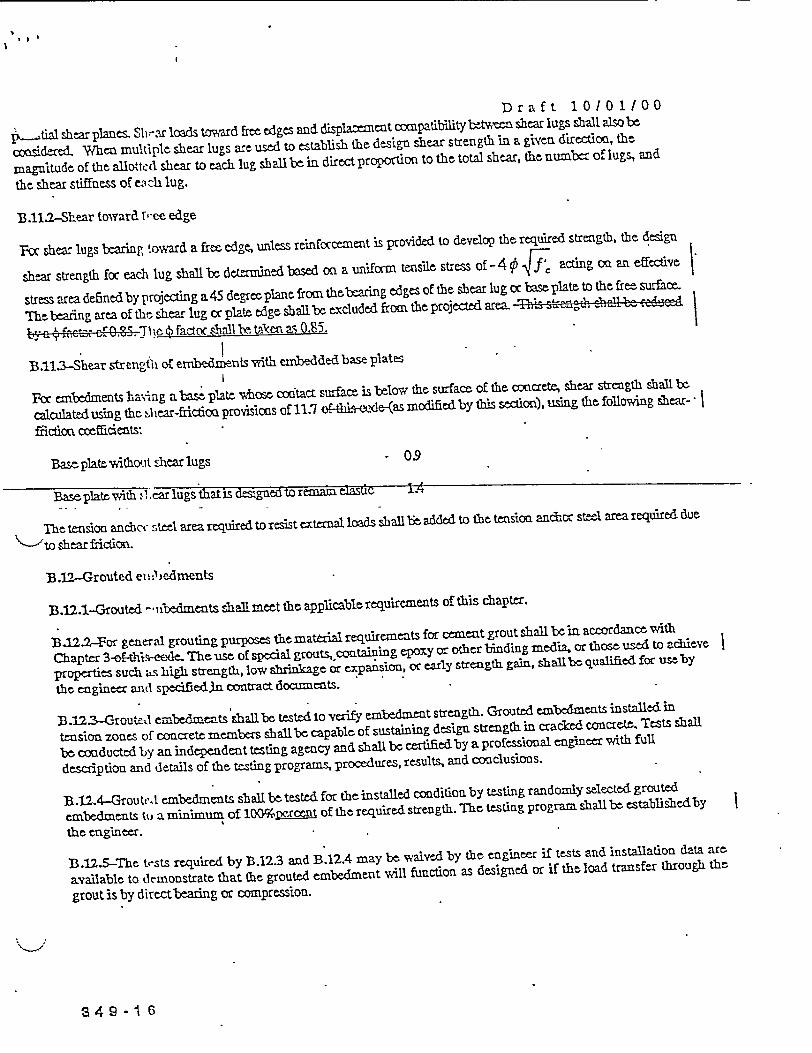
Draft 10101100
pktial shear planes Slit-r loads toward free edges and displacment conpatibility bwen shear lugs shall also be
o sidered- When multiple shear lugs are used to establish the design shear strength in a given direction, the
magnitude of the allotted shear to each lug shall be in direct proportion to the total shear, the number of lugs, and
the shear stiffness of eC ci lug.
13.11.2-Shear toward free edge
Yoc shear lugs bearing toward a free edge, unless reinforcement is provided to develop the required strength, the design
shear strength foc each lug shall be detamined based on a uniforn tensile stress of-4 ' 4 acting on an efective
stress area defned by projecing a 45 degree plane froc thebearing edges of the shear lug oc bsplate to the free surffce.
Thebeaing area of the shear lug cc plate edge shall be excluded from theprojected area- streag , gthhz |
t~ja t fa- cO. fact shall SeMta~en S 0Y85.
B .113-Shear strength of emnbedicnts with embedded base plates
Fcc embedments having a base plate whose cdtact surface is below the surface of the conacrete, shear strength shall be
calculated using the slJ ear-frictioa provisions of 11.7 us-cle (as moified by this section), using the following shear-
frictim cefidents:
Bascplatetithont slhcar lugs 09
Base plate with tl ear lugs that is desiged to reman eiasdc 1.4
The tension andcaq steel area required to resist external loads shall be added to the tension. anchor steel area required due
"---'to shear fricion.
B.12-Grouted et: )edments
B.12.1-Grouted --abedments shall meet the applicable requirements of this chapter.
13.12.2-For general grouting purposes thc material requirements for cement grout shall be in accordance with
Chapter 3-oi -eede. Th us of specal grouts, containing epomy or other binding media, or thosc used to acileve
properties such as high strength, low shrinkage or expansion, or early strength gain, shall be quaified for useby
the engineer and spedified.n contract documents.
B.123-Groutet embedments shall be tested to verify embedment strength. Grouted embedments installed in
tension zones of concrete members shall be capable of sustaining design strength in cracked concrete. Tests shall
be conducted by an independent testing agency and shal,l be certified by a professional engineer vith full
description and details of the testing programs, procedures, results, and conclusions.
B.12.4-Groutel embedmeats shall be tested for the installed condition by testing randomnly selected grouted
inbedmcents tu a minimum of lO0erXcent of the required strength. The testing program shall be established by
the engineer.
1B.12.5-The tests required by B.12.3 and B.12.4 may be waived by the engineer if tests and installation data are
available to demonstrate that the grouted embedment will function as designed or if the load transfer through the
grout is by directbeadng or compression.
349-1 6
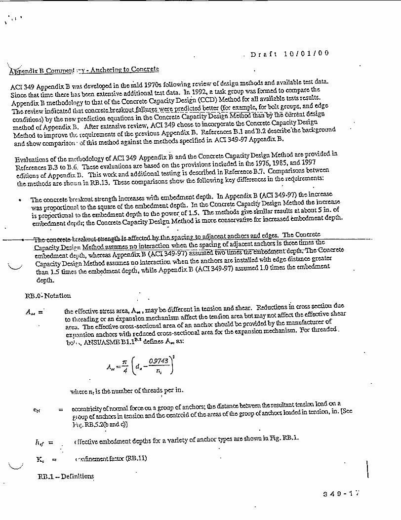
Draft 10/01/00
;i endlx B Coment -.Y - Anchorin? to Concrete
ACT 349 Appendix B v.-.s developed in the mid 1970s following review of design methods and available test data.
Since that time therehas been extensive additional test data. In 1992, a task group was formed to compare the
Appendix B methodology to that of the Concrete Capacity Design (CCD) Method for all available tests results.
The-reviw indicated tlat concretebrea ot alures ep cted better (for example, for bolt groups, and edge
conditions) by the new prediction equations in the Concrete Capacity Design Method tha6nb T-t cuIrrent design
method of Appendix B. After extensive revirw, ACI 349 chose to incorporate the Concrete Capacity Design
Method to improve thc requirements of the. previous Appendix B. References B.1 andB.2 describethebackground
and show comparison - of this method against the methods specified in ACI 349-97 Appendix B.
Evaluations of the methodology of ACI 349 Appendix B and the Concrete Capacity Design Method are provided in
References B.3 to B.b. These evaluations arcbased on the provisions included in the 1976, 1985, and 1997
editions of Appendix; B. This work and additioral testing is described in Reference B.7. Comparisons between
the methods are shov',,n in RB.13. These comparisons show the following key differences in the requirenents:
TIhe concrete breakout strength increases with embedment depth. In Appendix B (ACI 349-97) the increase
was proportional to the square of the embedment depth. In the Concrete Capacity Design Method the increase
is proportional to the embedment depth to the power, of 1.5. The methods give similar results at about 5 in. of
embedment de)pt; the Concrete CapacityDesign Method is more conservative for increased embedment depth.
-- Thc onemwbre- u" ang to adjacent anchors and edges. The Concrete
Capadty~iviP nMethod assumes no intcraction when the spacing of adjacent anchors is three times the
embedment depth, whereas Appendix B (AC1 349-97) assumed two times tle-etmnt Tdh7e-Concrete
Capacity Design Method assumes no interaction when the anchors are installed with edge distance greater
than 1.5 times the embedment deptih, while Appendix. B (ACI 349-97) assumed 1.0 times the embedment
depth.
R.O.- Notattion
A, the efective stress area, A.e, maybe. different in tensio and shear. Reductions in cross section due
to tlheading or an expansion nechanism affect the tention area but maynot affect te effective shear
area= The effective cross-sectional area of an anchor should be provided by the manufacturer of
expansion anchors with reduced cross-sectional area for the expansion mechanism. For threaded.
bol ,, ANSIJASME Bl.l-' defines A,. as:
(o9743'V09A=4 k 0e~)
whcr nr is th number of threads per in.
eo eatricity of normal force on a group of anchocs; the distancebettween theresultant tension load con a
gi oup of anchors in tension and the centroid of the areas of the group of anchocs loaded in tension, in. [See
I Ag. RB.5.2(b and c)]
(ffective embedment depths for a variety of anchor types are shown in Fig. RB.}.
,= (-infinement factor (1B.(11)
'RB.1 - Definitions
349- I "

Draft 10/01100
Alttle steet etement snud Ductile ,cteel element -Thc 14%f clonn tion shall bemeasured over thc eaze cnzth
Mstcified in tVi nppr ialtC AST standatd for the steel.
S % F-Me(He 'Thzt c; r t ltt
Vaaiaetkn rna K dz4znt- _ r : . 5 percent rr'actle -hc determination of the cocfficient K
iSc:nltd Vjth thic S nt fiactile, 3 - K de~nmds on the number of tests. n, used to com tte an d c.
Valuegof K idhke, for exa-mple, from 1.645 for n = -,-to 2.010 for n = 40, and 2.568 for n = 10.
RB3.2 - Scope
RB).2.1 - ACI 349 uses the term embedments to cover a broad scope that includes anchors, embedded plates, shear
lugs, grouted ernbed'taents, anid sgacialty inserts. It covers the same scope as was included in the 1997 code.
RB23 - Typical cm st-sn headed studs and headed bolts vith geometries consistent with ANSIJASMB B 1.11-s
B18.2.1,l9 and BlZ,.2.e'o have been tested andhave proven to beavcpredictably, so calculated pullout values
are acceptable. Post-installed anchors do nothavc predictable pullout capacities, and thercfore are required to be
tested.
IRB.2.6 - Typical embedment configurations are shown in Fg. RB.2.1 and RB.2.2. Thee figures also indicate the
extent of the embedaent within the jurisdiction of this code.
B "' - r rvqutilrernernts
PB.3.1 -When the strenoth of an anchor group is govermEd r la britgand
there is limitedre-listribution of the forces between the hiehlv stresed and less sressed anchors. In this case, the
theory of elasticity uirdt b used assug the attachment that distributes loads to thc anchors is
suficiently stiff. Thle forces in the anchors are considered to be proportional to the external load and its distance
from the neutral ;' s of the anchor group.
If anchor stregthl is goveredby ductile yielding of the anchor steel, significant redistribution of anchor forces can
occur. In this case, an analysis _O bsdi the theory of elasticity wilb conservative. References B.11 to
B.13 discuss nonlinear analysis, using the theory of plasticity for the determination of the capacities of ductile
anchor groups.
RIB3.3 - Many anchors ia a nuclear power plant must perform as designed with high confidence, even when
exposed to si nificant seismicloads. To prevent unqualified anchors being used. in connecdons wifch must
perform with hiph confidcae under significant seismic load, all anchors are required to be qualified for seismic-
zone usage by passing simulated seismic tests. jhe qualification shouldbe performed consistentvWith the
provisions of t is Appendix and should be reviewed by a professional engineer experienced in anchor technology.
Typical simul .ted seismic-testing methods are described in Reference B.7. For a post-installed anchor t6 beused
in conjunction with the requrements of this Appendix, the results of tests have to indicate that pullout failures
exhibit an arceptable load-displacement characteristic or that pullout fallures are precluded by another falure
mode. ACI 349 requires that all post-installed anchors be qualified, by independent tests, for use i cracked
concretc. /I.ichors aualified for use only in uncracked concrete arenotrecommendedinfnuclear power plant
structures.
The design of the anchors for impactive or impulsive loads is not checed directly by simulated seismic tests. An
anchor that has passed the simulated seismic tests, however, should function under impactive tensile loading in
cracked concrete.
RB .3.4 -T1te provisions 6f Appendix B are abplicable to normalweight concrete. Thc design of anchors in heavy
weigjht concrete should be based on testing for the spedficheavy weight concrete.
34 9-1 8
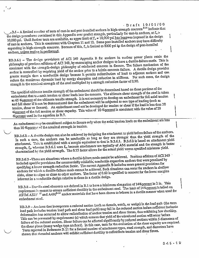
Dr af t 1 0101100
\< .3.5 - A limited xiuinber of tests of cast-in and post-installed anchors in high-strength coacrete 14 indicate that
the design procedures contained in this Appendix over predict strength, particularly for cast-in anchors, at fe >
10,000 psi. Until fuirher tests are available, an upper limit of f , = 10,000 psi imposed in th design
of cast-in anchors. MTis is consistent with Chapters 11 and 12. Somc post-installed anchors may have difficulty
expanding in high-strength concrete. Because of this, f c is limited to 8000 psi iy the design of post-installed
anchors, unless=611P it d..
R13.3.6.1 - The design provisions of ACI 349 Appendix B for anchors in nuclear power plants retain the
philosophy of previous editions of ACI 349, by encouraging anchor designs to have a ductile-fure mode. This is
consistent with the iutrength-design philosophy of reinforced concrete in flexure. the failure mechanism of the
anchor is controlle l ly requiring yield of the anchor prior to a brittle concrete failure. A ductile design provides
greater margin than a nonductile design'because it permits redistribution of load to adjacent anchors and can
reduce the maxirniuii dynamic load by enerjy absorption and reduction in stiffness. For such cases, the design
strength is the nominal strength of the steel multiplied by a strength reduction factor oE O.90.
The specified ultimate tensile strength of the embedment should be determined based on thoseportions of the
e rabedent that tra,;;smit tension or shear loads into the concrete. The ultimate shear strength of the steel is taken
as 65 %r tnt of the ultimate tensile strength. It is not necessary to develop an embedment for full axial tension
and full shear if it can be demonstrated that the embedment will be subjected to one type of loading (such as
tension, shear or flexure). An enbedmentneedfnot bc developed for tension or shear if theloadis less than 20
4pmcent of the full tension or shear capacity. This value of 20 %pArcent is consistent with the value of 20
qTcpercemt used in the equation in B.7.
An embedment nm:%.y b nsieredsubjecttoflceu only when the axial tension loads on the embedmeat are less
than 20 fkperg tut of the nomninal strength in tension.
RB 3.62 - A doctile design can also be achieved by designing the attachment to yield before failure of the anchors.
In such a case, the anchors can be nonductile so long as they are stronger than the -yield strength of the
atachiment. This is established with amargin equivalent to that in B3.6.1. B3.6. isbased on attachment yield
strength, f, whicreas B.3.6.1 uses , beauie attacmnts-rC typicall of A36 material and the strength is ber
characterized by the yield strength. The 0.75 factor allows for the actual yield. versus specified minimum yield.
RB3.63 -rnere are situations where a ductilefailure.mode cannotbe achieve& Previous editions of AC349
included specific provisions for commercially available, noaductile expansion anchors that vmepenalizedby
speifying a lowver stcength reduction factor. Th cuent AppcdixB includes moregeneraprovisions for
anchors fo vuwbich a ductile-failure mode cannaotbe achieved. Such situations can occur for anchors in shallow
slabs, close to ed ges or close to cther anchors. The factor of 0.60 is specified to account for the lowcr margins
inherent in a :onductile design relative to those in a ductile design.
B.3.S - Ducrile steel elemeats are defined in B. tobave a inimum elogation of 144%pen in 2 in. This
requirement i': meantto ensure sufficient ductility in the embedment steel. Thclimit of 149perentis bbedon
ASTM A325' '5andA490Q1'6 anchormaternals thathavebeen shown tobehavein a ductilemannerwhenused for
embedment stcel.
RP333.9 - AnChors that incorporate a reduced section (such as threads, notch, or wedge) in thcloadpath (thetermn
load path includes tension load path and shear load path) may fail in thereduced section before sufficient inelastic
deformation has occurred to allow redistribution of anchor tension and shear forces, thus cibting low ductility.
This can be prevented by requirement (a) which ensures that yield of the unreduced section wi occur befoce
failure of hic reduced section. Shear failurc can be affected slgificagtniy by reduccd setions vwithn 5 diameters of
the shear plane (many wedge type anchors). In this case, tests for the evaluation of the shear capacity arc required.
Tests reported in Reference B.1l for a limited number of attachment-types, steel strength, and diameters have
shown that threaded anchors will exhibit sufficient ductility to redistribute tension and shear forces.
34 s -I

Draft 101011003.10 -The design provisions for impulsive and. impactive loads in Appendix C may be used foi emnbedmerts.
Energy can be abscrdx-d by deformation of anchors designed for ductile steel failure.
RBA.4 - General reItil' rements for strength of structural anchors
R1- .4.1- This section provides the requirements for establishing the strength of anchors to concrete. The various
types of steel and cooct ete failuremodes foranchors are showaidigi iis. RB.4.l.(a) andRB.4.L(.b. Comprehensile
discussions of anchor failure modes are included in References B.1, B.2, and B.17. Any model that complies with
the requirements of B.4.2 and B.4.3 can be used to establish the concrete related strengths. For anchors such as
headed bolts, headed studs, and post-installed anchors, the concrete breakout design method of B.5.2 and B.6.2 is
acceptable. The anchor strength is also dependent on the pullout strength of B.53, the side-face blowout strength
ofB.5.4, and the minimum spacing and edge distances of B.S. The design of anchors for tension recognizes that
the strength of anchors is sensitive to appropriate installation; installation requirements are included in B.9.
Test procedures can also be used to determine the single anchor breakout strength in tension and in shear. The test
results, however, are required to be evaluated on a basis statistically equivalent to that used to select the values for
the concrete breakout method considered to satisfy provisions of B .4.2. The nominal strength cannot be taken
greater than te 5 '. frrcent fractile. The number of tests has to be considered in determining the 5 ;Ž±Ircent
fractilt.
RB.42 and 4 3 -- B.4.2 and B.43 establish the prformance factors for -which anchor design models are required
-to- b e vepanyeibae p oe he-exi sa- to Ossify teist-ing R'4 9.4
as long as swcea~t dataareavamidable to serifyihe. model.-
PB.4.2.1- The a~ddition of supplementary reinforcement in the direction of the load, confining reinforceent, or
both, can greatly enhance the strength and ductility of the anchor connection. Such enhancement is practical with
cast-in anchors such as those used in precast sectiois.
The shear strength of headedanchors-locatedneas theedge of amember cans b significantlyincreasedwithappropriate supplementary reinforcement References B.17 to B.19 provide information on designing suchreinforcement. Ihe effect of supplementary reinforcement is riot included in the concrete breakout calculatiommethod of B.5.2 and B.6.2. Ihe engineer has to rely on other test data and design theories to include the effects ofsupplementary reinforcement.
For anchors exC. eding thelimitations of D.4.22, for situations where geometric restrictions limit breakoutcapacity, or both, reinforcemaent proportioned to resist the total load, oriented in the dirtcion of load, within the
breakout 'risin and fully anchored onboth sides of thebreakoutplanes, maybeprovided instead of calculatingbreakout capacity.
The breakout :'rength of an unrein forced connection can be taken as an indication of the load at which significant
cracking will ascur. Such cracking can represent a serviceability problem if not controlled (seeRB.6.2.1).
RB .4.2.2 -Th e method for concrete breakout design included as considered to satisfy B.4. was developed from
the Concrete Capacity Design (CCD) Method, B-1Xa which was an adaptation of the xc Method, and is
considered to be accurate, relatively easy to apply, and capable of extension to irregular layouts. The CCD Methdpredicts the lhmd-bearig capacity of an anchor or group of anchors by using a basic equation for tensioa or for
shear for a single anchor in cracked concrete, and multiplying by factors that account for the number of anchors,edge distance, spacing, eccentricity, and absence of cracking. The limitations on anchor size and embedmentdepth are based on therange of test data.
349-2 0
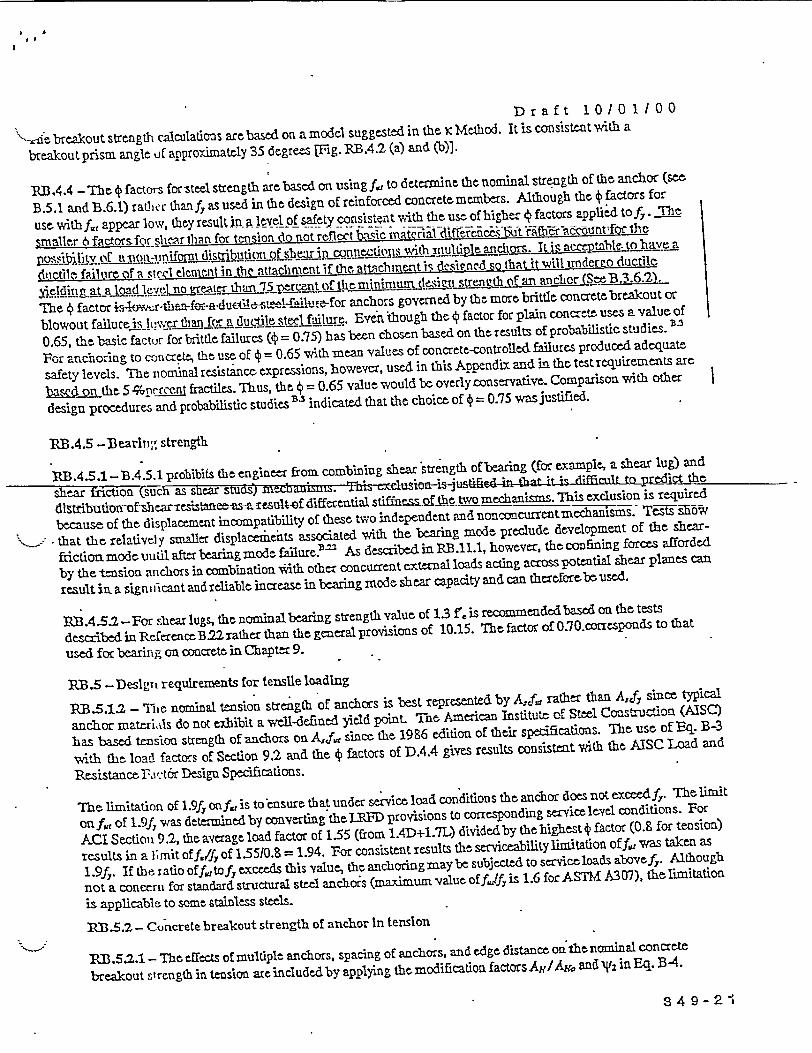
Dr a f t 1 /0 1 / O 0
""-oe breakout strength calculations are based on a model suggested in thx x Method. It is consistent vw'ith a
breakout prism angle u[ approximately 35 degrees Fig. RB.4.2 (a) and (b)].
F3R.4.4 - The 4 factors forsteel strength are based on usingf,11 to determine the norniral strength of the anchor (se
B.5.1 and B.6.1) raLthr thanfy as used in the design of reinforced concretemebers. Although the 41 factors for
use. with f,, appear low, they resultin ja leel of safety consistent with the use of higher^ § factors pplied tof. .fTh7
smaller 6facqsors herthafn for teasion tio notreflect buwxicmaterial difFer n ct rati LI
possibiltyc d ti n-!iniform lisibutipfselDric -u ons S p anchors. IL is aco pi L l _avca
ductile failure nf a sterl element ir the attachment if thG attachment rS desirned so that it will underao ductlet
eLqng tau l ~L et lj no trt lehan! 75 cenjt f ttminil _e of an anctor (See B3 .6,S)
1The 4 factor sl rfr anchors governed by the more brittle concrete breakout or
blowout failure JuwIt S er than Cor a tiucik t.eUtj fulure. Even 'though the 4 factor plain concret-e uses a value of
0.65, the basic factur for brittle failures (4 = 0.75) has been chosen based on the results of probabilistic studies.
For anchoring to o-kcrete, the use of 4 0.65 with mean values of concrete-controlled failures produced adequate
safety levels. The nominal resistance expressions, however, used in this Appendix and in the testrequirements are
bascd on the S %I)rss it fractiles. Thus, the 4 0.65 value would be overlyconservative. Comparison with other
design procedures and probabilistic studies B 3 indicated that the choice of 0.75 was justified.
P.B.4.5 -Bearlnr strength
11B.4.5.1 -B.4.5.1 prohibits the engineer from combining shear strength of bearing (for example, a shear lug) and
shear fiction (such as shcar studs) mecdazu1smj. ThAs cXbltTsiriusti0 dificultO t redict the
distb m-fsecarrscsmstaese.esultof 4iEfererial stiffas ofthc two mechanisms. This exclusion is required
because of the displacement incompatibility of these two independert and nonconcurrentmechanisms. TetRs EBW
* that the relativel y smaller displacements associated with the bearing mode preclude development of the shear-
frictionmodeouutil after bearing mode faflure.' As describedin PB.11.1, however, the confining forces afforded
by the tension anchors in combination *ith other concurrent external loads acting across potential shear planes can
result in. a signu *icant and rcliable increase in bearing mode shear capacity and can thecrefore'be used.
RB.4.5.2-For shear lugs, the nominal bearing strength value of 1.3 f', is reconmended based on the tests
described in Refe:receB.22rather than the general provisions of 10.15. The factor of 0.70.corresponds to that
used for bearing on concrete in Chapter 9.
RB.5 -Deslgrn requlrements for tensile loading
R3.5.12 - The nominal tension strength of anchors is best represented by A4fJi rather than Aid; since typical
anchor materials do not exhibit a well-defined yield point. The American Institute of Steel Ccastruction (AISC)
has based tesion strength of anchors on AIf; since the 1986 edition of their specifications. he use oF Eq. B-3
vwith the load factors of Section 9.2 and the 4 factors of D.4.4 gives results consistent with the AISC Load and
Resistance R cltor Design Specifications.
-The limitation of 1.9fy onf., is to ensure that under service load conditions the anchor does not exceedf 7. The limit
on f,, of 1.9fJ was determined by converting thIYRFD provisions to corresponding service level conditions. For
AC1 Section 9.2, the average load factor of 155 (from 1.4D+1.7L) dividedby the highest § factor (0.8 for tension)
results in a , mit of,,/fof 1-5510. = 1.94. For consistentresults the serviceability limitation off1 ,1 was taken as
1.9fy. If thtbiatiooff,dtofycxceed5 this valuc, thanchoringmaybesubjicted to servicloads abovf,. Although
not a concerti for standard structural steel anchors (maximum value offff is 1.6 for ASTM A3 07), the limitation
is applicable to some stainless steels.
113.5.2 - Concrete breakout strength of anchor In tenslon
113.5.2.1 - The effects of multiple anchors, spacing of anchors, and edge distance oa the nominal concrete
breakout strength in tension are included by applying the modification factors Av/Ay, and N' in Eq. B4.
3 4 9-2 I

Draft 10/0 1/00
hf.<B.5.1 (a) shows Ag., and the development of Eq. (B-5). Ay. is the maximum projected area for a single
anchor. Fig. RB5.1 (b) shows examples of the projected areas for various single-anchor and multiple-anchor
arrangements. Because AN is the total projected area for a group of anciors, and Ayo is the area for a single
anchor, there is no n1ee to include a, the number of anchors, in Eq. (B-4a) or (B-4b). If anchor groups arc
positioned in such a v v that their projected areas overlap, the value of As is required to be reduced accordingly.
RB.5.2.2 -. The basic equation f6r aclior capacity was d-rived B assuming a concrete failure prism
wiLh an angle of abot 35 degrees and coasideing fracture mechanics concepts.
The values of k were 4I ternined from a large database of test results in uncracked concrete B. au the 5 percent |
fractile. The values V.anre adjusted to corresponding k values for cracked concrete.B I. B2 5 For anchors with a deep
embedment depth (ht, , 11 in.) some test evidence indicates using hy can be overly conservative in some cases.
Often, such tests hav. been performed with selected aggregates for speal applications. An alternative expression
(Eq. B-6b) is providrc' using h513 for evaluation of cast-in anchors with 11 in. <ha <25 in. The limit of 2S in.
corresponds to the upper range of test data. This expression can also be appropriate for some undercut post-
installed anchors. 3 '1.2, however, should be used with test results to justify such applications.
RB .5.23 -For anchors influenced by three, or more edges where any edge distance is less than 1.5 hcr, the tensile
bce akout.strength computed-by the ordinary CCD Method, which is the basis for Eq. (B-6), gives misleading
results. This occurs because the ordinary definitions of A1 A/,O do not correctly reflectthe edge effects. If the value
af hnlls ilutec toii~.,, wnerec~rs taciargest ofxrlua cinug, cdged~Listu~ ~la1cess Am or-equam --
-the-actual -1-Sha, this problem-sc ree.d is-s hown-by-lautz 3-5 Ahis~miiingwvalue ofi5eiudifl,,Q-,B6,B-7, andB-6. Tnis approachis bestunderstood when applied to an actual case. Fig. R3.5.2 (a) showshow
Chic failure surface, as tihe samt area for any embedmentdepthbtyoad theproposedlimit onha (taken ash'Wein the
figure). In this cam~ple, theproposedlimit on the value of hr= c,,l,1 5 tobeused in the computations results in
We= hr 4 in J .5 = 2.67 in. This would be the proper value to be used for hf in computing the resistance, for
this example, evet k if the actual rmbedmnent depth is larger.
RB .5.2.4-Fig. l; u.5.2 (b) shows dimensaion ca = ef for a group of anchors that is in tension but that has a
resultant force eccentric with respect to the centroid of the anchor group. Groups of anchors can be loaded in such
a way that only some of the anchors arc in tensionuTFig. RB.5.2(c)]. In this case, only the anchors in tersion are to
be considered in letermining cat. The anchor loading has to be determined as the resultant anchor tension at an
eccentricity with respect to the center of gravity of the anchors in tension. Eq. B-7 is limited to cases where
ear < s12 to alert the designer that all anchors may notboe in tension.
RB.52.5 - If anthors are located close to an edge so that there is not enough space for a complete breakout prism
to deielop, the, luad-bearing capacity of the anchor is further reduced be~ymd that reflected in AtAx,. If the
smallest side cover distance is greater than 1.5 bG a complete prism can form and there is no reduction (C2 = 1).
If the side cover is less than 1.5 hb, the factor, W12, is required to adjust for the edge effectl
RB.5.2.6 - Te -mnalyses for cracking should consider all specified load combinations using unfactored loads,
including the ef fects of restrained shrinkage.
_RB7 5.s2;7'--Anchors that perform well in a crack that is 0.012 in. wide are considered suitable for use in cracked
concrete. If widcr cracks are expected, confining reinforcement to control the crack width to about 0.012 in.
should be provided.
349 -22
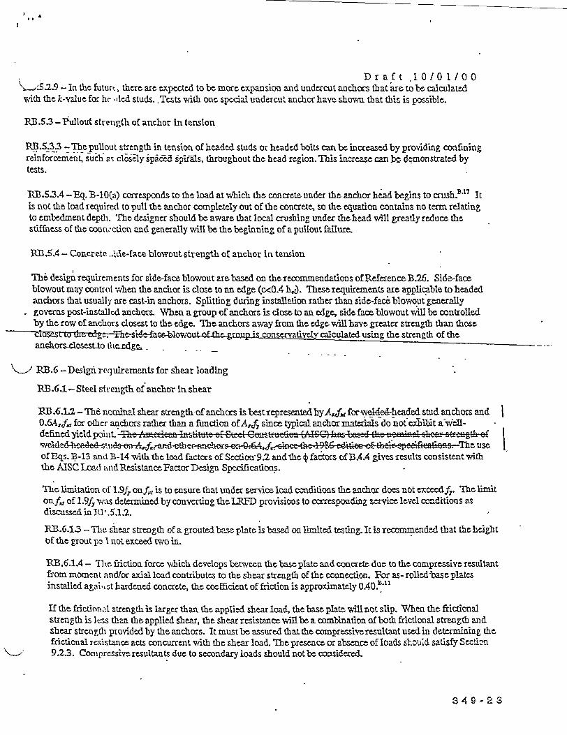
6
Dr aft .10/0 1/00.5.2.9 - In the futurt, there are expected to be more expansion and undercut anchors that are to be calculated
with the k-value for hr .led studs. Tests with one spedal undercut anchor have shown that this is possible.
RB3.5.3 -Thllout strength of anchor In tension
RB.5.3.3 -Thepullout strength in tension of headed studs or headed bolts canbe increasedby providing confiningreinfsrcement1 such as closely sipacd §p`ifgs, throughout the head region. This increase can be demonstrated bytests.
k13.5.3.4 -Eq. B-lO(a) corrcsponds to the load at which the concrete under the anchor bead begins to crush.Y " Itis not the load required to pull the anchor completely out of the concrete, so the equation contains no term relatingto embedment depth. The designer shouldbe aware that local crushing under thchead will greatlyreduce thestiffness of the couivction and generally will be the beginning of a pullout failure.
RB.5.4 - Concrete .. ide-face blowout strength of anchor In tension
The design requirements for side-face blowout are based on the recommaendations of Reference B.26. Side-faceblowout may contro -when the anchor is close to an edge (c<0.4 he). Thse requirements are applicable to headedanchors that usually are cast-in anchors. Splitting during installation rather than side-fac blowout generallygoverns post-installcd anchors. When a group of anchors is close to an edge, side face blowout will be controlledby the row of anchors closest to the edge. The an chors away from the edgec vwll bav greater strength than thoseCls G L c -Tht-st ae t g sconservatively calculatedusing the strength of theanchors-closesto theedgfe.,
> hRB.6 -Deslgni ret3ulrements for shear loading
nB .61- Steel st rength of anchor In shear
RB.6.1.2 - Tle r.oal shear strength-of anchors is bestrepresentedbyA,f, for elde4-headed stud anchors and0.6Af; for other anchors rather than a function of AJ since typical anchornmaterials do not exhibit a Well-defined yield point. Thc Amec. Inzntuti er Eteet Coz"tf n (tSC) L ns bzizd the naenirel -hcar stgth ofv&dcldzd e.tu,,i-i . ffielinhor -o 0.6. zlhce thc 1925 rUiti 0f thr 3p-fifficoi. euseof Eqs. B-13 andB -14 'Aththe load factors of Setion 9.2 andthe factors ofB.4 gives results cmsistentwiththe AISC Load ..nd Resistance Factor Design Spcifications.
The limitation of 1.9f onf is to ensure that dcr seice load oditions the anchor does not exceedf Te limitonf.d of 1.9f, was deternined by converting the I D provisions to correspoding service level conditions asdiscussed in 10 .5.1.2.
RB.6.1.3 - Tlie shear strength of a grouted base plate is based on limited testing. It is reconmended that theheightof the grout pD I not exceed two in.
RB.6.1.4- Tte. friction force which develops between the baseplate and cocrete due to the compressive resultantfrom moment andlor axial load contributes to the shear strength of the connection. For as- rolledtbase platesinstalled agai .st hardened concrete, the coefficient of friction is approximately 0 4 0AL "
If the frictional strength is larger than the applied shear load, the base plate will not slip. When the frictionalstrength is ]ess than the applied shear, the shear resistance will be a combination of both frictional strength andshear strength provided by the anchors. It must be assured that the compressive resultaut used in determining thefrictional resistance acts concurrent with the shear load. Ihtpresence or abscrce of loads sr..u'd satisfy Sectihn-9.2.3. Compressive resultants due to secondary loads should not be considered.
3 4 9 - 2 G

Draft 10101100I 2 - Concrete breakout strength of anchor In shear
RB .62.1.- The shear-strength equations were. developed from the CCD method. They assume a breakout concangle. of approximately 3S degrees [Fig. RB.4.2 (b)] and consider fracture mechanics theory. The effects ofmultiple anchors, spacing of anchors, edge distance and thickness of the coacretemember on nominal concretebreakout strength in shtar are included by applying the reduction factor A VAv, and Vst in Eq. (B-16). For anchorsfar from theedge, B.6..'. usually will not govern. For these cases, B.6.1 and B.6.3 often govern.
Fig.RB.6.2 (a) shows A, 0 and the dcyelopment ofBq. (-17). Ay0 is thermaximum projected area for asingleanchor that approximates the surface area of the. full breakout prism or cone for an anchor unaffectedby edgedistance, spacing, or depth of member. Fig. RB.6.2 (b) shows examples of the projected areas for various single-anchor and multiple-anchor arrangements. Ay approximates the ful surface area of the breakout cone, for theparticular arrangement of anchorsi Since Av is the total projected area for a group of anchors, and Ay, is the areafor a single anchor, 1)ereisnone~d to include the number OL anchors in the equation.
The assumption sho;.'n in Fig. RB..6.2 (b) with the case for two anchors perpendicular to the edge is a conservative,interpretation ofthetlistribution of theshear forceonX an elastic-basis. Iftheanchors arewelded to acommonplate, when the anchor nearest the front edge begins to form a failure cone, shear load would be transferred to thestiffer and stronger rear anchor. For cases where nominal strength is not controlled by ductile. steel elements, B.3.1specifies that load (- rects be determined by elastic analysis. It has been suggested in the PCI Desimg Handbookapproach B27 that tlhe increased capacity of tnh anchors away from the edge be considered. Because this is areasonable approach, assuming that the. anchors are spaced far enough apart so that the. shear failure surfaces do- 1 l u il;2tssc B. G o oir T the fii sufaces do not intersect, as Would generally occur if-the-anchor-spacint, s, is, qua eater than 15c,, then after formation of the nearedge failure surlace, thc - --
%igher capacity of the load. As shown i ettom exampleig-- -kRB.6.2 (b), cousidcring the full shear capacity to be provided by this anchor with its much larger resisting failure
surface is appropriate. No contribution of the anchor near the edge is then considered. Checking the ncar-edgeanchor condition to predlude undesirable. cracking at service load conditions is advisable. Further discussion ofdesign for multiple anchors is given in RefEcrence B.17.
For the case of anchors near a corner subjected to a shear forc 'ith components normal to each edge, asatisfactory solution is toi e e cedk indeendlently the. contiedon for eadh component of thc shear force. |Other specialized cases, such' as (he hear resistance of anc'hor groups where all anchors do not have the sameedge distance, art treated in REereace B.18.
The detailed pru ,-isions ofB.6.2.1 (a) app'lyto thcase of shear forc directed towards an edge. When the shearforce is directd away from the. edge, the strength will usually be goernmedby B.6. or B.6.3.
The case of sht ir force parallel to an edge iB.6.2.1 (c)] is shown in Fig. RB.62 (c). A special case can arise wzithshear force pai iflel t, te. cdge near a corner. Take the example of a single ancho near a corer [Fig. RB.6.2(d)1.If the edge distwnce to the side c2 is 40 %per t or more of the distance clin the direction of the load, the shearstrength parall el to that edge can be computed directly from Bq. B-16 using clin the direction of the load.
RB .6.2.2 - I-ike the concrete breakout tensile. capacity, the concrete. breakout shear strength does not increasc withthe failure sur face, which is proportional to c?. Instead, the strength increases proportionally to cts, due to thesizt effect. lie. capacity is also influenced by thc anchor stiffinss and the anchor diameter. B 1 '
The constant 7 in the shear strength equation vwas determined from test data reported in Reference B,1 ats the 5S9P9rcesnt fr-,.Ueilc adjusted for cracking.
3 4 9 - 2 At

Draft 10/01/00.23 - For the spr-cial case of cast-in headed bolts rigidly welded to an attachment, test data B show that
somewhat higher shear capacity exists, possibly duc to the stiff welding connection clamping the bolt moreeffectively than an atachment with an anchor gap. Because of this, the basic shear value for such anchors isincreased. Limits are imposed to ensure sufficient rigidity. The design of supplementaryreinfoccecment isdiscussed in Referenc'rs B.17 to B.19.
R13 .6.2.4 - For anchors influenced by three or more edges where any edge distance is less than 15cL, the shearbreakout strength coniputed by the basic CCD Method, which is the basis for Eq. B-18, gives safe but misleadingresults. These special cases were studied for the - Method E T.and the problem was pointed out bytLutz. tzsSimilar to the approach used for tensile breakouts in B.5.2.3, a correct evaluation of the capacity is determined ifthe value of c in Bos. B-18, B-19, B-20, and B-21 is limited to hl1.5. This is shown in Figur RPB.6.2(g).
RB.6.2.5 -This section provides a modification factor for an eccentric shear force towards an edge, on a group ofanchors. If the shear load originates above thecplanc of the concrete surface, the shear shouldfirstberesolved as ashear in the plane of the concrete surface, vwith a momant that can or cannot also cause tension in the anchors,depending on the normal force. Fig. RB.6.2 (c) defints the term c for calculating thet T5 modification factor thataccounts for the fact that more shear is applied on one anchor than the other, teading to split the concrete near anedge. If e > s/2, the CCD procedure is not applicable.
1113.6..6 F;. l"3.E.2 (f) s:cvz the dimenion c~ -
RB.6.2.7 -Torque-controlled and displacernentcontxoiIec expansi zc - k r ce=under pure shear loa&.
RB .6.3 - Concrti e pryout strength
RB .6.3 -Refere mcc B.I indicates th at the pryout shear resistance can bh approximated as 1 to 2 times the anchortensile resistanc' with the lo-etf value appropriate for hr less than 2.5 in.
RB.7 - Intera c ton of tensile and shear forces
The shear-tension interaction epression has traditionally been expressed as:
where ca varies from 1 to 2.
The. current tri-linear recommendation is a simplification of the expression where a= 513 (Fig. RB.7). The limitswere chosen to eliminate the requirement for computation of interaction effects where very small values of thesecond forct ;,re present. Any other interaction expression that is verified by test data, however, can be used underB.43.
RB1.8 - Reqn ! red edge distances, spacings, and thicknesses to preclude splitting failure
The minimimn srpacings, edge distances, and thicknesses are very dependent on the anchor characteristics.Installation forces and torques in post-installed anchors can cause splitting of the surrounding concrete. Suchsplitting can also be-produced in subsequent torquing during connection of attacbments to anchors including cast-in anchors. The primary source ofvalues for minimum spacings, edge distances, and thicknesses of post-installed
3 A 9 - 2 5

Draft lO/1100
a :s should be the product-specific tests. In some cases, however, specific products are not known in the design
stage Approximate values are provided for use in design.
RB .8.2 - In thc abscm of product-specific test infamation, at the design stagc the uunimnum cetr-to-nter spacing for
post-installed anchors mavy be taken as 6d,.
RB.8.3 -The edge cover over a deep embedment close to the edge can have a significant effect on the side-face
blowout strength ofB.5.4. The engineer can use cover larger than the normal conicrete cover requirernents to
inacrease the sidt-face blotwout strength.
B .8.4 - In the absence of product-specific test information, at the design stage the tninimum edge distance may be taken
asnotless than:
Underocit ancr,-s 6d-
Tcxque-contr ,'led expansion anchors
Deformation-. ontrolled empansio anchors 10d.
If these values are us'l in design, the project drawings andproject specifications should specify use of anchors witvf
mninum center-to-c' iater spacing and edge distance as assumed in design.
Hmdsed-an cI= Ck1 to-e-gei 4 d-tOS reeut of the design strength.
' .8.4 -DriMing -tdIes for post-installed anchors can causemicroo:acking. Therequilrement for atminimum edge
-istance=2 times th. iaximuim aggregate size is to minimnze the effects of such microcracking.
RB.11 - Shear ca I, -%city of embedded plates and shear lugs
RB.1l.1 - Shear I rgs
The code requirements for the design of shear lugs are based on testing reported in Reference B.22. This testing
confirmed that shear lugs arc effective with axial compression and tension loads on the embedment, and that the
strength is increased due to the confinement aff~oded by the tension anchors in combination, with external loads.
The shear streagth1 of the embedment is the sum of the bearing strength and the strength duc to councnment.
The tests also revlaed two distinct response modes:
1. A beaming ni':d characteized Jby shear resistance from direct bearing of shear lugs and inset faceplate edges
on concretc or grout augmented by shear resistance from confinement effects associated with tension anchors
and extern: . concurrent axial loads, and
2. A shear-friction mode such as defined in 11.7 of the code.
The embedments first respond in the bearing mode and then progress into the shear-friction mode subsequent to
formation of f ;l fracture planes in the concrete in front of the shear lugs or base plate edge.
The bearing strength of single shear lugs bearing on concrete is defined in B. 4.5. For multiple lugs, the shear
strength should not exceed the shear strength b-etwen shear lugs is defined by a shear planbetwecn the shear
lugs as shown in Fig.RB.11-1 and a shear stress linited to 10 54 with 4 equal to 0.85.
349 -2G

D X a f t Io/ 0 1 1 0 0anchorage shear strength due to con finement can be taken as Kc(N, - P.), with < equal to 0.85, where N, is
tbstrength of the tension anchors in accordance with B.5.1 and P, is the factored external axial load on theanchorage. (P. is positive for tension and negatlve for compression.). This considers the effect of the tensioaanchors and external loads acting across the initial shear fracture planes (see Fig. RB.11-1). When P, is negativc,the provisions of Section 9.2.3 regarding use of load factors of 0.9 or zero, must also be considered. Theconfinerent coefficieni, KA, given in Reference B.22, is as follows:
K,: = 1.6 for inset base plates without shear lugs br for anchorage vith multipleshear lugs of height, h,
and spacing, ., (clear distance face-to-face between shear lugs) less than or equal to 0.13 hi.
K, = 1.8 for . nchorage with a single shear lug located a distance, h, or greater from the front edge of the
base plate oi with multiple shear lugs and a shear lug spacing, s, greater than 0.13 h-VE.
These values of confiement factor, K,, are based on the analysis of test data. The different Kc values for plateswith and without shea.r lugs primarily reflect the difference in initial shear-fracture, location with respect to thetension anchors. The tests also show that the shear strength due to confinement is directly additive to the shearstrength determined by bearing or by shear stress. The tension anchor steel area required to resist applied momentscan also be utilized for determining N., providing that the compressive reaction from the applied moment actsacross the potential shear plane in front of the shear lug.
For inset base plates, the area of the base plate edge in contact with the concrete cn be used as an additional shear--- thgp-bearbg-area-provading dcgarment comnatibilitv with shear lugs can be demonstrated. This requirement can
zsatisfiedbydesigning the shear lug to remain elastic under factor design oaplus flexure) less than 0.01 in.
For cases such as ia grouted installations where thebottdm of the baseplate is above the surface of the concrete,the shear-lug-bearing area should be limited to the contact area below the plane defined by the concrete surface.This accounts for the potential extension of the initial shear fracture plane (formed by the shear lugs) beyond thep&rimeter of the l-ose plate, that could diminish tht effective bearing area
Multiple shear lugs should be proportioned by considering relative shear stiffness. When multiple shear lugs areused near an edge, the effective stress area for the concrete design shear strength: shold be evaluated for theembedment shen i at each shear lug. -
kB.113 - She - strength of embedments with embedded base plates
The coefcient of 1.4 for embedmcnts with shear lugs reflects concrete-to-concrete ffictioa afforded byconfinement of concrete between the shear lug(s) and the base plate (postbearing mode behavior). This valuecorresponds to the friction coefficient of 1.4 recommended in 11.7 of the code for concrete-to-concrete friction andis confirmed it tests discussed in ReferenceB.22.
R..13-ConII arlsonof Concrete Capaclty eslgnMethod andACI 349-97
The following sections provide comparisons of the capacities of anchors in accordance with the Concrete CapacityDesign Methodl (included in this edition of ACI 349) against those calculated in accordance with the previousprovision of ACI 349 Appendix B (ACT 349-97).
RB.13.1- Co ncrete breakout strength of a single headed stud in tension
Fig. RB.13-lshows the concrete breakout strength of a single anchor in tension (3 3Nb) in concrete with acompressive strength of 4000 psi. The CCD method in cracked concrete is from Eq. B-6a of the code with ;-24
349 -27
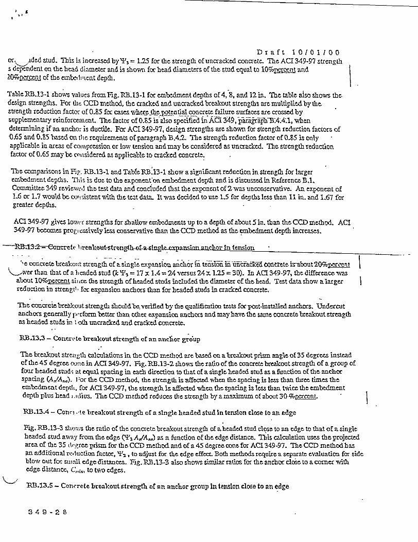
Draft 10/01100ori dd stud. Ihis is increased by ,3 = 1.25 for the strength of uncracked concrete. The ACI 349-97 strengths dcpendent on the head diameter and is shown for head diameters of the stud equal to 10%rei!Lt andaZOpetrcent of the embedvient depth.
Table RB.13-1 show's values fromrFig. RB.13-1 for embedment depths of 4, 8, and 12 in. The table aiso shows thedesign strengths. For th C'CD method, the cracked and uncrackedbreakout strengths are multiplied by thestrength reduction factor of 0.85 for case-s wkcre tepoential concrete failure surfaces are crossed bysupplementary reinforcement. The factor of 0.85 is' also specified in ACl 349, paragraphB.4., whendetermining if an anchor is ductile. For ACI 349-97, design strengths are shown for strength reduction factors of0.65 and 0.85 based on thle requirements of paragraph B.4.2. The strength reduction factor of 0.85 is onlyapplicable in areas of coinpression or low tension and may be considered as uncracked. The strength reductionfactor of 0.65 may be cn;isidered as applicable to cracked concrete.
The comparisons in FR. 3RB.13-1 and TableIB.13-1 show a significant reduction in strength for largercn.bedmnet depths. Tlis is due to the cxponent on embedment depth and is discussed in Reference B.1.Committee 349 reviewe.3 the test data and conciuded that thc exponent of 2 was unconservative. An exponent of1.6 or 1.7 wouldbe consistenttwith thetest data. Itwas deided to use 1.5 for detthsless than 11 in. and 1.67 forgreater depths.
ACI 349-97 gives loNvtc strengths for shallow embedments up to a depth of about 5 in. than the CCD method. ACI349-97 becomes prog i ssively less conservative than the CCD method as the embedment depth increases.
i3 --'e re t-strength-hot-alsle ypdna nn anchor In tension
'e concrete breakoutt strength of a single expansion anchor in te i-h cacked tcete is-bout 2O~rvt |\,,er than that of a Iteaded stud (k 73 = 17 x 1.4 = 24 versus 24 x 1.25 =30). In ACI 349-97, the difference was
about 10 prce~nt sit mCe the strength of headed studs included the diameter of the head. Test data show a largerreduction in strengl. for expansion anchors than for headed studs in cracked concrete.
The concrete bretkout strength slouldle verified by the qualficatio tests for post-inst~aled anchors. Undercutanchors generally p'rform better than other expansion anchors and may have the same concrete breakout strengthas headed studs in, oth uncracked and cracked concrete.
RB13.3 - Concrete breakout strength of an anclkor group
The breakout streL-th calculations in the CCD method are based on a breakout prism angle of 35 degrees insteadof the 45 degree xoule in ACI 349-97. Fig. RB.13-2 shows the ratio of the concrete breakout strength of a group offour headed studs at equal spacing in each direction to that of a single headed stud as a function of the anchorspacing (A,/A,.,). F or the CCD method, the streagth is affected when the spacing is less than three times theembedment deptil, for ACI 349-97, the strength is affected when the spacing is less than twice the embedmentdepth plus head i.tdius. The CCD method reduces the strength by a maximum of about 30 % x6rcent
RB.13.4 - Conn, . te breakout strength of a single headed stud In tension close to an edge
Fig. RB.13-3 slwov, s the ratio of the concrete breakout strength of aheaded stud closc to an edge to that of a singleheaded stud away from the edge (' AT,/A^) as a function of the edge distance. TIhis calculation uses the projectedarea of the 35 Olec ree prism for the CCD method and of a 45 degree cone for ACI 349-97. The CCD method hasan additional reduction factor, '2, to adjust for the edge effect. Both methods require a separate evaluation for sideblow out for sti all edge distances. Fig. RB.13-3 also shows similar ratios for the anchor close to a corner withedge distance C, to two edges.
k13.13.5 - Concrete breakout strengthl of an anchor group In tenslon close to an edge
3 4 9 - 2 8

Dr a f t 1 0 0 1 / 0 0ig .13-4 shows the ratio of the concrete breakout strength of a group of four headed studs losc to an edge toaatM 0the same anchor grutip away from thc edge as a function of the edge distance, C,.,,,. The ratio is influenced)y the spacing of the ancho s and this figure applies to four headed studs with embedment depth of 6 in., spacing)f 6 in. and head diameter of 0.6 in. The figure also shows simtilar ratios for the anchor group closa to a cornerwith edge distance, C,.,,, to two edges.
REFEREN-CES
BA Fuchs, W., Eligehausen, R., and Breen, I., "Concrete Capacity Design (CCD) Approach for Fastening toConcrete," ACI Structural Journal, V. 92, No. 1, January-February 1995, pp. 73-93. Discussion - AC!Structural Journal, V. 92, No. 6, November-December 1995, pp. 787402.
B.2 Bligebausen, K, aid Balogh, T., "Behavior of Fasteners Loaded in Tension in CrackiedReinforcedConcrete," Acr Structural Journal, Vol. 92, No. 3, May-June 1995, pp. 365-379.
13.3 Farrow, CB., anl lYlugner, RLE., 'Tensile Capacity of Anchors with Partial or Overlapping FailureSurfaces: Evain ution of Existing Formulas on an LPr-D Basis," ACI Structural Journal. V. 92, No. 6,Novemnbr-Deceaiber 1995, pp. 698-710.
B.4 Farrow, C. B., IVrigui, I., and Klingner, R. E., 'Tensile, Capacity of Single Anchors in Concrete: Evaluationof Existing Formiulas on an LRFD Basis," ACI Stractural Journal, V. 93, No. 1, Janwary-February 1996.
B.5 Shirvani, M., -Behavior ofTensile Anchors in Concrete: Statistical Analysis andDeseignRecornmendations," (M.S. thesis, Departnent of Civil Engineering, he, University-of Texas at Austin, May
NiutiL ", Pehaviof-Shear--Anharsin Concrete: Statistical Analysis and Design1 cou s,(M.S. thesis, Departmeat of Civil Engintering, The. Ulniersity ot Tcas ast, j-,Y498 .) .
. '.7 "Anchor Bolt Behavior and Strength during Earthquakes," NUREGICR-5434, August, 1998
B.8 ANSIIASMFi 1T1.1 "Unifidlnch Screw Threads (UN andU.NRThreadForm), ASbME, Fairfield, NJ, 1989.
B.9 ANSIIASMi I B18.2.1, -Square and Hax bolts and Screws, Inch Series," ASME, Fairfiedd, NJ, 1996.
B&10 ANSI/ASMYI) 1 B18,2.6, 'Tasteners for Use in Structural Applications," ASME, Fairfield, NJ, 1996.
B.11 Cookl R A, and Elingner, R E., "Behavior ofDtictile Multiple-Anchor Steel-to-Concrete Connectionswith Surface.-Mounted Baseplates, " Anchors in Concrete: Design and BRehavior (SpecW Publication SP-130), Geori- A. Senkiw and Harry B. Lancelot mT, eds., American Concrete Institute, Detroit, Michigan,February V.|?92, pp. 61-122.
B.12 Cook,PR A., and Klingner,R E., "DuctileMultiple-Anchor Steel-to-ConcreteConnectioas," Journal ofStructural E'nginecring, ASCE, V. 118, No. 6, June 1992, pp. 1645-1665.
B.13 Lotze, D)., and Klinguer, R B., 'Behavior of Multiple-Anchor Attachments to Concrete from thePerspectiv.' of Plastic Theory, 'Report PMFSEL 96-4, Ferguson Structural Engineering Laboratory, TheUniversity of Texas at Austin, March 1997.
B.14 Primavera, E. J., Pinelli, J. P., and Kalajian, E. R, 'TensileBehavior of Cast-in-Place and UndercutAnchors in High-Strength Concrete," ACI Structural Journal, V. 94, No. 5, Septembber-October 1997, pp.583-594.
B.15 ASTM A,325, "High-strength SteelBolts for Structural Steel Joints"
B.16 ASTM A490, "'Heat-treated Steel Structural Bolts, 150,C00 psiMin_. . tnsle Strength"
3 4 9 - 2 9

Draft 1 0/0 1/00B!,,Design of Fostenin; s in Concrete, Comitetfuro-International du Bcton (CEB), Thomas Telford Services
Ltd., London, Jan. '997.
B.18 Fa-stenings to Con, rcel and Masorny Structures, State of the Art Report, Cornite uro-Intermational duBeton, (CEB), Bulltin No. 216, Thomas Telford Services Ltd., London, 1994.
B..19 Klingner,kjenmonca, J., and Malil, T., 'Effect of Reinforcing Details on the Shear Resistance of AnchorBolts under Revex;cd Cyclic Loading~," Jouiiial Uft he-Atmerican-Concrete Institite, V. 79, Mo. 1, 1982. pp.3-12.
B.20 Eligehausen, R., Fuchs, W., and Mayer, B., "Load Bearing Behavior of Anchor Fastenings in Tension,"Betonwerk + Fei ti .teiltechnik, 12/1987, pp. 826-832, and 1/1588, pp. 29-35.
B.21 Eligehausen, P. -,.nd Yuchs, W., 'Load Bearing Behavior of Anchor Fastenings under Shear, CombinedTenrsion and Shtear or F.exural Loadings," Btaonwerk + Fertigteiltechnik, 211988, pp. 48-56.
B.22 Rotz, J. V., and RPeifschneider, M., 'Combined Ayial and Shear Load Capacity of Embeddments inConcrete, " 10th International Conference, Strctutral Mechanics in.Reactor Technology, Anaheim,California, .Al-st, 1989.
B..23 ASTM A307, "Carbon Steel Bolts and Studs, 60,000 psi Tensile Strength"
_ Anchor Connections in Crackced Concrete," (Ph.D. diss., TheUniversity of texaiat Aust August 1997.)
.25 Lutz, L., 'Di :cussion to Concrete Capacity Design (CCD) Approach for Fastening to Concrete," ACIStructural Journal, November-December 1995, pp. 791-792 and authors closure, pp. 798-799.
B.26 fiE he, L., anidEligehausme, R, Tateral Blow-outFailure of Headed Studs Near aFreefdge," Anchors inConcrete: DIesign and Behavior (•p-cfarPubiccaton SP-13 o, cor--S eniw-aniiarry B. Lan clotIII, eds., Amrvican Concrete Institute, Deticot, Michigan, Febrary 1992, pp. 235-252.
B.27 PCI Des.;g: Handbook - Precast and Prestrcssed Concrce, 2nd-Sth Editions, Prestressed ConcreteInstitute, Cilcago, 1978.
B.28 Wong, T.L., "Stud Groups L oaded in Shear (M.S. thesis, Oklahoma State University, 1988.)
B.29 Shaikh, A'; 1., and Yi, W., 'In-place Strength of Welded Studs,' PCI Jowrnal, V.30 (2), March-April 1985.
3 4 9 -30

Draft 1 0 1 /0 1 10
TABLE BA.13-1COMCRETE BREAKOUT STRENGTEI OF A SINGLE UEAIDED STUD
(Concrete Strength = 4000 psi)
* bThe strength for embedment depths of 4" and 8" is calculated using equation B-7a; the strength for theermbedrment depth of 12 is calculated'using equation B-7b.
349-31

Draft 10/0 1/00
MKFRICVERSION.0 Change trits as follows: in. shall be mm; in. shall be timE; psi shall be MIPa; lb shall beN.
\' .1 Change 2 in. to 50 mm.B.3.5 Change 10,000 psi to70 MPa and change 8000 psi to 55 MPa
BI.4.2.2 Change 2 in. to 50 mm and change 25 in. to 625 mm.B15.1.2 Change 125,000 psi to 860 MPa.B5.2.2 Change, .= 24 tok= 10, changek= 17 tok=7, change k= 16 tok= 6.7, change 11 in. to280 mm,
nd-change 25 in. to 635 mm.13.5.4.1 In EquaLion B-1l, change 160 to 13.3.B.6.1.2 Change 125,000 psi to 860 MPa.B.6.2.2 In Equation B-18a; change 7 to 0.6.13.6.2.3 Change 318 in. to 10 mm.*B.6.23 In Equation B-18b, change S to 0.66.B.6.2.7 Chanve #4 to #13 and 4 in. to 100 mm.B.63.1 Chanme 2.5 in. to 65 mmn.B.8.5 Channe 4 in. to 100 mm.RB .5.2.2 Change 11 in. to 280 mn, change 25 in. to 635 mm.
RP..5.23 Change 4 in. to 100 mm; change 2.67 in. to 67 mmn.PB.5.2.7 Change 0.012 in. to 03 mm.RB1.6.2.2 Change uconstantT to "constant 0.6.'RP.6.3 Change 2.5 in. to 65 mm.Fig. P.B.52(a) Change 4 in. to 100 mm; change 8in. to 200 mm; change 2.67 in. to 67 mm.
349-32