engineering bulletin #102 front coverpalmoilis.mpob.gov.my/publications/poeb/poeb104.pdf · pome:...
TRANSCRIPT
PALM OIL ENGINEERING BULLETIN NO. 104 1
Engineering Bulletin #102
front cover
ISSUE NO. 104 (July - Sept. 2012)
LEMBAGA MINYAK SAWIT MALAYSIAMALAYSIAN PALM OIL BOARD
KEMENTERIAN PERUSAHAAN PERLADANGAN DAN KOMODITI MALAYSIAMINISTRY OF PLANTATION INDUSTRIES AND COMMODITIES, MALAYSIA
Website: www.mpob.gov.my

PALM OIL ENGINEERING BULLETIN NO. 104 1
EDITORIAL BOARD
ChairpersonDatuk Dr Choo Yuen May
MembersDr Lim Weng SoonAb Aziz Md Yusof
SecretaryIr N Ravi Menon
Malaysian Palm Oil BoardMinistry of Plantation Industries and Commodities,
MalaysiaP. O. Box 10620, 50720 Kuala Lumpur, Malaysia
Tel: 603-8769 4400Fax: 603-8925 9446
Website: www.mpob.gov.my
© Malaysian Palm Oil Board, 2012All rights reserved.
No part of this publication may be reproduced, stored in a retrieval system, in any form or by any means, electronic,
mechanical, photocopying, recording, or otherwise, without the prior written permission of the publisher.
Products and services advertised in thisPalm Oil Engineering Bulletin do not
connote endorsement by MPOB.
Editorial
see page 2
CONTENTS
Editorial
TRAINING AND SEMINARSMPOB Training Programme 2012
MPOB Conferences/Seminars 2012
FEATURE ARTICLESInnovation Potentials in Palm Oil Mill Design
The Present Status and Potentials of Biogas Production and Utilisation for Palm Oil Mills-based Residues
Achieving a BOD below 20 mg litres-1 for POME: Is it a Myth or a Reality?
DATASHEET Standard Milling Product Losses
1
7
9
21
49
33
8
Most millers are aware that process control is a very important tool for conducting
good milling practice. It is verily the ‘eyes’ of the whole process operation. It is of paramount importance for the mill management to ensure that it is not only done regularly but that it is also done with a good measure of zeal and truthfulness, so that the ensuing results accurately reflect the losses and quality of palm products at different stages of process operation. Large plantation companies in Malaysia have well-organised process control departments with a network of routine inspection schedules, carried out by its specialists stationed in their head office. However, this is not replicated by some private companies, as it may be to reduce operational costs. This may be akin to penny wise and pound foolish approach as even for a small mill, the role of process control is something that it can ill afford to totally ignore.
Process control is a fundamental acti-vity in any produce line as only it can effectively guide the personnel in charge to continuously alter the process course to follow the desired targets. If this is not followed religiously, the process direction may take a dangerous and often costly route culminating in heavy losses to the company. Unfortunately for the affected mills, the inherent weakness of its process control system often goes un-noticed basically due to low importance being given to process control activities. Process control should therefore not be envisaged as a waste of time by millers, as its implication on productivity far outweighs the cost of establishing and operating a process control unit in a mill.
Under the National Key Economic Area (NKEA), one of the Entry Point Projects (EPP) is to raise the mill oil extraction rate (OER). In order to implement this effectively, the accuracy of the laboratory analysis of the oil lost in empty fruit bunches (EFB), mesocarp fibre and sludge is extremely important. Among these, probably the highest oil loss

PALM OIL ENGINEERING BULLETIN NO. 1042
from page 1
CALL FOR ARTICLESPersonnel of the palm oil mills are invited to send in articles of relevance to the palm oil industry in Malaysia for publication in Palm Oil Engineering Bulletin. By sharing your expertise you will be helping the industry and the nation as a whole. The topics of interest are:
1. Plant modifications done in your mill that resulted in improvements in milling operation or main-tenance.
2. Innovations done in your mill that produced improvements in the operation of the mill and that you are willing to share them with others.
3. Any special work done in your mill that directly resulted in improvements in OER and product quality.
Please submit your article to us and we shall be pleased to publish them in Palm Oil Engineering Bulletin. Feel proud to have your articles published in this Bulletin that is circulated throughout the industry and MPOB offices worldwide.
is in EFB. The analytical results of oil lost in EFB with reasonable level of accuracy using the prevailing quartering system of sampling is highly questionable. Even this analysis is seldom carried out by some of the private mills. Some established plantation-based mills conduct this test once or twice a year and use these analytical results for all EFB oil loss calculations, while some others assign a zero value for this. The oil lost in EFB is closely related to the percentage of overripe bunches in the FFB consignment, as well as the overfeeding of threshing machine or its feed conveyors.
In spite of exponential growth of the palm oil industry worldwide no reasonably accurate method of quantifying the oil lost in EFB has been devised to date. The main issue is the undependable sampling procedure, which can only be described as ludicrous.
The EFB sampler picks up one bunch from every train of 300 EFB moving slowly along the conveyor. At the end of the day or the next day the samples are quartered a few times, until the sample size is brought down to a manageable size of a mere 50 g to extract the oil in the sample. A better method is the full solvent extraction of the oil from the whole bunch but this is not at all practical, as it tends to be costly and time-consuming.
Perhaps the industry should look into the possibility of using a near infrared (NIR) analyser or similar devices that could continuously scan the moving EFB to capture data. The data can then be converted to give the actual oil content in EFB. This project may be undertaken by any research-minded miller. If successful, the system could be patented. The oil lost in EFB has to be measured accurately in order to modify the milling logistics, so that it can pave the way for bringing down oil loss.

PALM OIL ENGINEERING BULLETIN NO. 104 7
Training & Seminars
MPOB TRAINING PROGRAMME SCHEDULE 2012
CODE NO.
TITLE DATE VENUE
A COURSES1 OIL PALM
A1.1 Kursus Operator Mekanisasi LadangTahap 1 dan 2 Mac-Ogos PLASMA, KeratongTahap 1 dan 2 Sep-Feb PLASMA, Keratong
A1.2 Kursus Pengurusan dan Penyelenggaraan Tapak Semaian SawitBil. 4: Wilayah Utara 11-12 Sep Hotel Orient Star,
Lumut, PerakBil. 5: Wilayah Tengah 16-17 Okt Hotel Klana Resort,
Seremban, Negeri Sembilan
2 PALM OIL A2.1 Diploma in Palm Oil Milling Technology
& Management (DIPOM)Semester III 2-11 Jul PLASMA, Lahad DatuExam Semester III 3-4 Sep PLASMA, Lahad Datu
A2.2 The 26th MPOB Oil Palm Products Surveying Course 2-6 Jul New York Hotel,Johor Bahru, Johor
The 25th MPOB Oil Palm Products Surveying Examination
20-22 Nov Premier Hotel, Klang
A2.3 Kursus Penyelia Kilang Minyak Sawit 3-7 Sep MPOB HQA2.4 Colour Cosmetic Course 8-12 Oct MPOB HQA2.5 Kursus Kemahiran & Pengetahuan Asas Rawatan
Tertiari Efluen Sawit9-11 Okt Hotel Emas,Tawau,
Sabah29-31 Okt Hotel Imperial, Miri,
Sarawak20-22 Nov PLASMA, Keratong

PALM OIL ENGINEERING BULLETIN NO. 1048
Forthcoming Events
For enquiry or further information, please contact:
HRD & Conference Management UnitTel. No. : 03-8769 4400 ext. 4865, 4867Fax No. : 03-8925 7549E-mail : [email protected]’s website : www.mpob.gov.my
All information are correct as at press time.
B MPOB CONFERENCES/SEMINARS 20121 National Seminar on Palm Oil, Milling, Refining and
Quality (POMREQ)27-28 Nov Magellan Sutera
Harbour Resort, Sabah
2 Transfer of Technology Seminar and Exhibition 2012
3 Dec Kinta Riverfront Hotel, Perak
3 Fourth IOPRI-MPOB International Seminar 13-14 Dec Hotel Bandung, Indonesia

PALM OIL ENGINEERING BULLETIN NO. 104 9
Feature Article
* Malaysian Palm Oil Board, P. O. Box 10620, 50720 Kuala Lumpur, Malaysia. E-mail: [email protected]
Innovation Potentials in Palm Oil Mill DesignN Ravi Menon*
INTRODUCTION
orizontal sterilisers are in dire need for improvement. There is great potential for university students to explore the field
of sterilisation. It has been found that the sterilisation process practiced by the industry is not founded on sound process technology. There is ample room therefore for improvement not only in the field of sterilisation, but in many other areas of processing as well. In this article, we would focus on sterilisation, the least understood process operation.
The weakness of the sterilisation process stems from its inefficient de-aeration system. Millers have tried single peak, three peaks and multiple peak sterilisation but none of these made any spectacular impact on sterilisation efficiency as such. To begin with, even a thermometer is conspicuously absent in most sterilisers, as without it, the millers will not know the impact of the operation of Dalton’s law of partial pressures on the temperature of steam/air mixture within the steriliser.
Some 30 years ago the millers were very enthusiastic in improving sterilisation efficiency. Various methods of sterilisation
regimes were tried out to improve de-aeration, so that the percentage of un-stripped bunches remained within limits. Now, bunch crushing and double stripping operations are widely accepted by the industry, as the norm for addressing the consequences of poor stripping efficiency, which served only to effectively camouflage the cause of poor stripping performance.
The problem lies in the lack of under-standing of one of the fundamental principles of thermodynamics. Crushing the partially stripped bunches, followed by second stripping does not remove the original problem of inefficient sterilisation. The mill engineers are encouraged to probe into this matter, so that their attention is focused on the actual cause of the problem. Let us take a close look at the inefficient stripping problem and find out whether it can be solved at the source rather than at the consequence.
At present, the mill process depends solely on the sterilisation efficiency based on the percentage of fruits still remaining in the bunch after the stripping operation is completed. As sterilisation efficiency is a function of the temperature within the steriliser, we should not wait for the actual results of the stripping operation to find out that the stripping had been unsatisfactory, when it is too late. It is more logical to just monitor the thermometer reading and become fully aware that the sterilisation
H

PALM OIL ENGINEERING BULLETIN NO. 10410
Feature Article
had indeed been inadequate in real time, even before opening the steriliser door.
The normal sterilisation steam pressure is 3 barg that should have a saturation temperature of 143.6°C. This is indeed a good temperature for sterilisation. This can occur only if the whole steriliser chamber is filled up with steam. What we really have here is a mixture of air and steam. One fundamental mistake in the steriliser instrumentation is that in almost all our mills the thermometer is missing and it would probably not cost more than RM 50. A thermometer can readily tell the engineer, the volume of residual air that still remains in the steriliser after completing the de-aeration operation. It can tell whether the sterilisation had been effective or not.
Everything that is happening within the steriliser in terms of heat transfer to the FFB is reflected by the temperature displayed by the thermometer. Millers may try single peak, triple peak or multiple peak but the efficiency of the impending stripping operation can be predicted by the temperature within the steriliser. We do not have to wait for the actual stripping results.
If throughout the sterilisation time the temperature within the steriliser never exceeded 120°C it can be easily predicted that the sterilisation will be poor. If on the other hand, the temperature remain steady at 130°C or above, the efficiency of sterilisation would undoubtedly be good.
Measuring the temperature is only one part. It will just tell us the sterilisation efficiency that can be expected from the prevailing temperature within the steriliser. It does not tell us how we must address the issues in order to improve the sterilisation efficiency. There is only one parameter that has to be made right, and that is the residual air within the steriliser and it is strongly linked to the temperature.
For this to happen we have to maximise de-aeration. This is not easy to carry out
due to many constraints. One obstacle is the high volume of air trapped within the steriliser. No matter how many peaks we set in our sterilisation regime, it is still not possible to realise complete evacuation of air in the steriliser. Let us discuss a popular hypothesis postulated by some in the milling industry. When bunches are heated, the air trapped within bunches will be continuously released. The incoming steam may not be able to push out all the air as they may form pockets encapsulated by steam with no escape route for it during de-aeration. The initial steam flow into the steriliser chamber could be highly turbulent due to high steam velocity followed later by laminar flow when the velocity drops due to low pressure differential between the incoming steam pressure and the steriliser chamber pressure. During the turbulent flow regime, it is possible for the air to form pockets and to remain as pockets without discharging until the steam capsule is dissipated by condensation that may take place at a later stage when sterilisation is nearly completed. As the air pockets are poor conductors of heat, and they are dominant during the early stages of sterilisation within the steriliser, the heat transfer between the steam and bunches can be expected to be poor.
Generally, the mills maintain the last peak for about 30 min with the de-aeration peaks being slotted at the beginning of the cycle. Now assume we start with a 5 min first peak to get rid of most of the air. This can be followed by a second full peak of 20 min pressure cooking, a third peak of 5 min intermediate de-aeration, an additional 20 min full peak pressure cooking and culminate with a 5 min blow off giving a total sterilisation time of 65 min. We are not sure whether this would give better results or not but it does provide for a good air release after bunches are properly heated. The mill engineers are encouraged to carry out different variations of this to arrive at the ideal system. Many innovations of this nature based on basic engineering principles have not been carried out.

PALM OIL ENGINEERING BULLETIN NO. 104 11
Feature Article
CONTINUOUS BLEEDING
Continuous bleeding of condensate was the norm in the early days of the industry but the new engineers or mill designers seem to have overlooked its importance and decided to ignore it as something useless! The continuous release of condensate as well as the air that is continuously released from bunches could effectively nullify the relatively low steam temperature corresponding to the low partial pressure of steam within the steriliser. Some sacrifice of steam is imminent when the condensate bypass is kept open throughout the sterilisation cycle. Probably, a further study is still necessary to ensure the efficient separation and expulsion of air from the condensate pipe. Air bottles fitted with spring loaded relief valves installed on the condensate bypass line can effectively release the air from the air bottle when the air pressure builds up (Figure 1). Other methods also may be available in the market for air release.
Steam Ejectors
These are effective but need high pressure steam for rapid air ejection. If mills have excess steam it is worthwhile to try this to partially evacuate the air prior to the admission of steam. In this case, care must be taken to prevent the collapse of the steriliser shell caused by excessive evacuation of air. A protective system must be incorporated to break the vacuum when it reaches a pre-set value.
Figure 1. Steriliser with air bottle fitted with relief valve on condensate bypass line.
Vacuum Pumps
This is a slow process for producing vacuum especially in big vessels like sterilisers. Steam ejectors generate vacuum at a faster rate than vacuum pumps and as such this is not recommended as a suitable system.
Steam Admission Points
This can play an important role in de-aeration process. The current design of air release through the exhaust pipe as practiced by many mills does not appear to be an efficient system for de-aeration. As the air is heavier than steam it will tend to stay at the bottom while the lighter steam will remain at the higher plane. What will happen when steam is admitted in a steriliser containing full of air? When steam is admitted into the steriliser the steam pressure will build up to form the first peak, during which time the exhaust and condensate valves will be generally closed. As the steam gets into contact with the cold air some steam will condense and the enthalpy of condensation of steam (latent heat) will be transferred to the air, thus raising its temperature. The quantity of steam condensed will continuously be replaced by the incoming steam. The pressure indicated on the pressure gauge now will be the sum of the partial pressure of air at the elevated temperature (not at the atmospheric temperature any more) plus the partial pressure of steam.
STERILISER RELIEF VALVE
COND. BYPASS LINE

PALM OIL ENGINEERING BULLETIN NO. 10412
Feature Article
Now let us consider what happens to the air immediately surrounding the bunches. As the bunches are encapsulated by a thick layer of air and is held firmly by the live layer of steam the air cannot escape is unable to form the pockets. If it cannot, then during the blow-off operation, most probably, only the steam hovering above the cages will be blown out and not necessarily the air. When eventually the steam pressure is reduced to zero then there is good chance for the air to be evacuated. But in most mills the pressure is kept at half the initial value. There is another area where some modifications can be made to avoid encapsulation of air. The steam can be admitted at the side.
A SENSIBLE APPROACH FOR ACCOMPLISHING GOOD
DE-AERATION
As air is lighter than steam and the steam pressure will most certainly press down the air, the possibility of air finding a way to pass through the only escape route through the steam, is indeed a mystery. It would make sense if the blow off pipe is located at the bottom, the only problem to this being the large volume of condensate that will accumulate at the bottom of the steriliser during the initial stage of heating.
This tendency for condensate accumu-lation can be addressed by keeping the condensate valve open during the initial 5 min of sterilisation followed by an intense pressure build-up and de-aeration of say 15 min through large blow-off pipes located at the bottom say 0.5 m above the conden-sate outlet so that large volume of air can be released in a relatively short time and at the same time avoid the blow out of con-densate. The air that is released could pass through a cyclone to reduce its kinetic en-ergy before discharging it into the atmo-sphere, so that blow off operation does not contribute towards excessive noise level. This is shown in Figure 2.
The above suggestion in no way rules out the possibility of unexpected practical obstacles that could render the proposed system to remain only as a hypothesis. The readers are kindly requested to participate in a dynamic discussion through the Palm Oil Engineering Bulletin on how to improve our milling techniques. We know that some of the engineers in the mills have good ideas but find it difficult to implement it or express it due to the lack of authority to do so. But you can always pool your resources and express it through the Palm Oil Engineering Bulletin. All suggestions are welcome.
Figure 2. Steriliser fitted with air release header and cyclone.
PALM OIL ENGINEERING BULLETIN NO. 10414
PALM OIL ENGINEERING BULLETIN NO. 104 21
Feature Article
The Present Status and Potentials of Biogas Production and Utilisation for Palm Oil
Mills-based ResiduesTong, S L * and Lee, A L *
* Oiltek Nova Bioenergy Sdn Bhd, Lot 6, Jalan Pasaran 23/5, 40300 Shah Alam, Selangor,
Malaysia. E-mail: [email protected]
ABSTRACT
he rapid growth of biogas plants in Malaysian palm oil mills in recent times can be attributed to the keen interest of the industry to reduce
the greenhouse gas (GHG) emissions from palm oil production, coupled with the potential benefits which can be realised by capturing and utilising the large quantities of biogas to produce renewable energy. During the initial development in the last five to six years, we have observed the applications of the various anaerobic digester technologies for biogas recovery mainly from palm oil mill effluent (POME) treatment systems, where to date, close to 10% of the palm oil mills have installed some forms of biogas-capture systems. Exponential growth is expected with this trend extending to cover all of the approximately 1000 mills in the ASEAN region. With the expansion of the biogas industry, the potential of the next generation biogas production using alternate sources can be expected. Palm oil mill residues, like POME slurry, solid palm waste materials (empty fruit bunches and oil palm by-products)
can become alternative or supplementary feedstock materials, to give much higher biogas yields than that from POME. Accompanying this development, various methods of utilisation of the biogas generated has been realised, but it was limited mainly to on-site applications in accordance with site specific factors. These include applications for thermal energy recovery in the different types of boiler systems and for power generation via gas engines for on-site use or connection to the grid. However, the challenges still remained for development of off-site utilisation for the biogas recovered. Prospective applications after upgrading of the biogas (biogas refining), such as compressed natural gas (CNG) equivalent (transport fuel), feeding to natural gas (NG) pipeline and bottling, and transportation for offsite industrial use, also can be foreseen.
INTRODUCTION
The capture of biogas from palm oil mill effluent (POME) treatment system using a closed-tank anaerobic digester system by the palm oil industry has been reported since the early 1980s (Quah and Gilles, 1981; 1984). However, due to the high cost of construction and the lack of economically attractive utilisation of the biogas recovered,
T
PALM OIL ENGINEERING BULLETIN NO. 10422
Feature Article
there has been, until very recently, only one successful closed-tank anaerobic digester system built in nearly 400 palm oil mills in Malaysia (Chua and Gian, 1986; Tong and Bakar, 2005). The system which has been in continuous operation for over 27 years to date is the one at Keck Seng Palm Oil Mill in Masai, Johor, which is located next to a palm oil refinery complex, with high demand for energy supplies.
However, a rapid growth of new POME biogas plants has been observed over the last five to six years. The main motivating factor for this development is the desire to reduce the greenhouse gas (GHG) emissions which lead to a reduction in the carbon footprints during palm oil production. The other benefit is capturing of the large quantities of biogas for utilisation as a form of clean renewable energy (RE).
This article reviews the methane production potentials, technology and the utilisation development extending from the present generation of POME biogas plants to the development of the large scale next generation biogas production, making use of other abundant palm oil mill biomass residues or by-products as feedstock materials.
METHANE PRODUCTION POTENTIALS OF PALM OIL MILL BIOMASS
RESIDUES
Palm oil represents the largest proportion of the world’s vegetable oil production in recent decades. The combined world palm oil production of 45.06 million tonnes and palm kernel oil of 5.21 million tonnes in 2009 accounts for 36.02% of the total world vegetable oil production at 139.59 million tonnes. The combined total for Malaysia and Indonesia at 18.50 and 20.75 million tonnes, respectively, amounts to 87% of the total world palm oil production. On this basis, the scale of biomass residues availability from the oil palm plantation and palm oil industrial sector has been recognised as an important resource of biomass feedstock for RE generation.
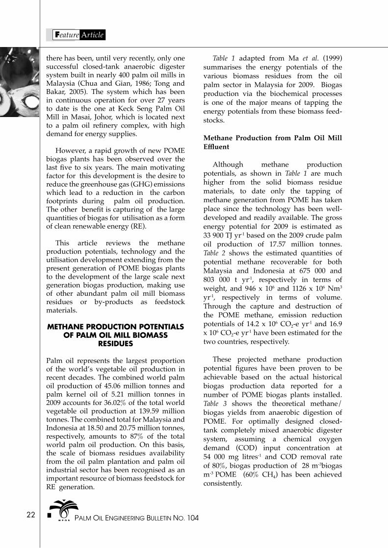
Table 1 adapted from Ma et al. (1999) summarises the energy potentials of the various biomass residues from the oil palm sector in Malaysia for 2009. Biogas production via the biochemical processes is one of the major means of tapping the energy potentials from these biomass feed-stocks.
Methane Production from Palm Oil Mill Effluent
Although methane production potentials, as shown in Table 1 are much higher from the solid biomass residue materials, to date only the tapping of methane generation from POME has taken place since the technology has been well-developed and readily available. The gross energy potential for 2009 is estimated as 33 900 TJ yr-1 based on the 2009 crude palm oil production of 17.57 million tonnes. Table 2 shows the estimated quantities of potential methane recoverable for both Malaysia and Indonesia at 675 000 and 803 000 t yr-1, respectively in terms of weight, and 946 x 106 and 1126 x 106 Nm3
yr-1, respectively in terms of volume. Through the capture and destruction of the POME methane, emission reduction potentials of 14.2 x 10⁶ CO2-e yr-1 and 16.9 x 10⁶ CO2-e yr-1 have been estimated for the two countries, respectively.
These projected methane production potential figures have been proven to be achievable based on the actual historical biogas production data reported for a number of POME biogas plants installed. Table 3 shows the theoretical methane/biogas yields from anaerobic digestion of POME. For optimally designed closed-tank completely mixed anaerobic digester system, assuming a chemical oxygen demand (COD) input concentration at 54 000 mg litres-1 and COD removal rate of 80%, biogas production of 28 m-3biogas m-3 POME (60% CH4) has been achieved consistently.
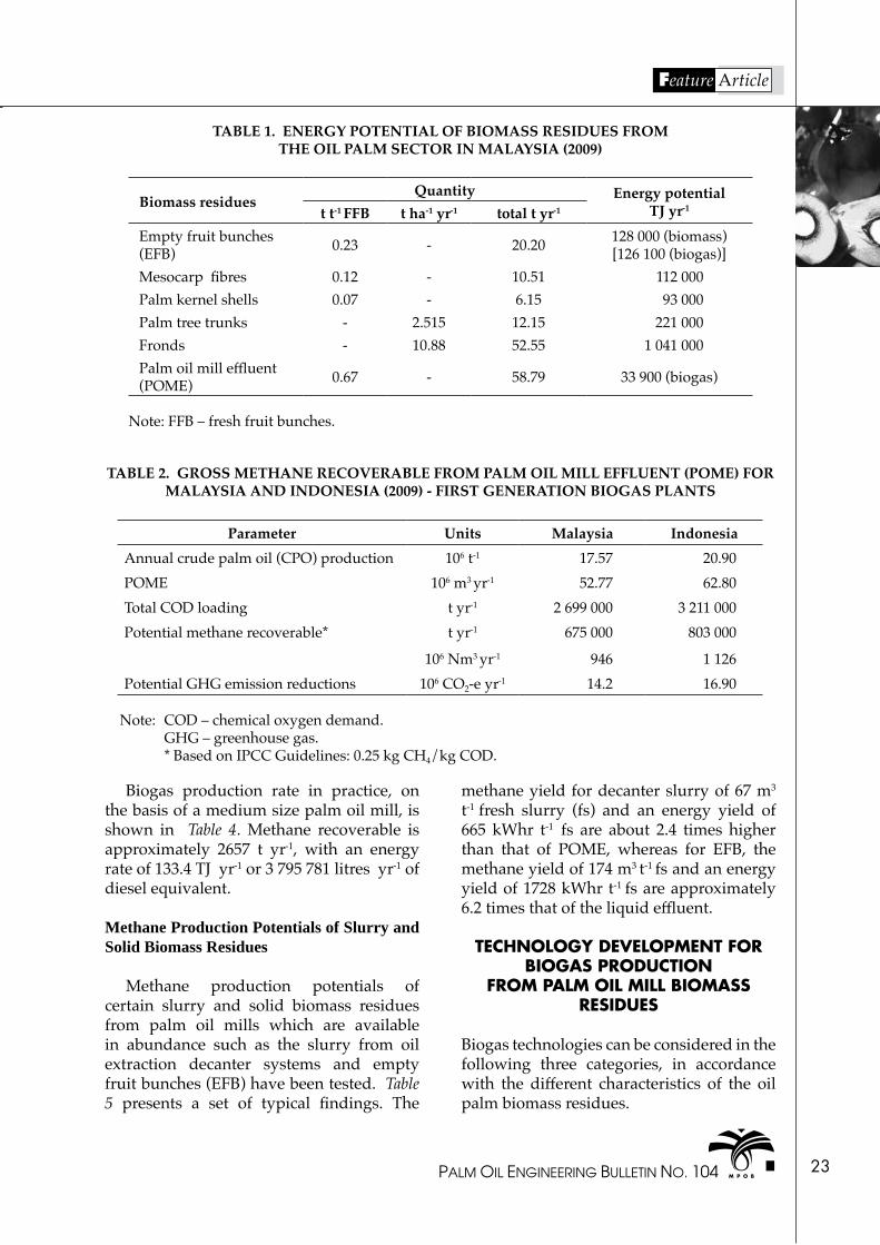
PALM OIL ENGINEERING BULLETIN NO. 104 23
Feature Article
TABLE 1. ENERGY POTENTIAL OF BIOMASS RESIDUES FROM THE OIL PALM SECTOR IN MALAYSIA (2009)
Biomass residuesQuantity Energy potential
TJ yr-1t t-1 FFB t ha-1 yr-1 total t yr-1
Empty fruit bunches (EFB) 0.23 - 20.20 128 000 (biomass)
[126 100 (biogas)]Mesocarp fibres 0.12 - 10.51 112 000Palm kernel shells 0.07 - 6.15 93 000Palm tree trunks - 2.515 12.15 221 000Fronds - 10.88 52.55 1 041 000Palm oil mill effluent (POME) 0.67 - 58.79 33 900 (biogas)
Note: FFB – fresh fruit bunches.
TABLE 2. GROSS METHANE RECOVERABLE FROM PALM OIL MILL EFFLUENT (POME) FOR MALAYSIA AND INDONESIA (2009) - FIRST GENERATION BIOGAS PLANTS
Parameter Units Malaysia IndonesiaAnnual crude palm oil (CPO) production 106 t-1 17.57 20.90POME 106 m3 yr-1 52.77 62.80Total COD loading t yr-1 2 699 000 3 211 000Potential methane recoverable* t yr-1
106 Nm3 yr-1
675 000
946
803 000
1 126Potential GHG emission reductions 106 CO2-e yr-1 14.2 16.90
Note: COD – chemical oxygen demand. GHG – greenhouse gas. * Based on IPCC Guidelines: 0.25 kg CH4/kg COD.
Biogas production rate in practice, on the basis of a medium size palm oil mill, is shown in Table 4. Methane recoverable is approximately 2657 t yr-1, with an energy rate of 133.4 TJ yr-1 or 3 795 781 litres yr-1 of diesel equivalent.
Methane Production Potentials of Slurry and Solid Biomass Residues
Methane production potentials of certain slurry and solid biomass residues from palm oil mills which are available in abundance such as the slurry from oil extraction decanter systems and empty fruit bunches (EFB) have been tested. Table 5 presents a set of typical findings. The
methane yield for decanter slurry of 67 m3
t-1 fresh slurry (fs) and an energy yield of 665 kWhr t-1 fs are about 2.4 times higher than that of POME, whereas for EFB, the methane yield of 174 m3 t-1 fs and an energy yield of 1728 kWhr t-1 fs are approximately 6.2 times that of the liquid effluent.
TECHNOLOGy DEVELOPMENT FOR BIOGAS PRODUCTION
FROM PALM OIL MILL BIOMASS RESIDUES
Biogas technologies can be considered in the following three categories, in accordance with the different characteristics of the oil palm biomass residues.

PALM OIL ENGINEERING BULLETIN NO. 10424
Feature Article
Anaerobic digestion of POME
• Organic substance: 1% to 6% total solids.
• Technology: complete-mixed stirred-tank reactor (CSTR) for anaerobic digestion – first generation biogas plant.
TABLE 3. THEORETICAL METHANE/BIOGAS YIELDS FROMPALM OIL MILL EFFLUENT (POME) ANAEROBIC DIGESTION
Theoretical methane yieldNm-3 CH4 kg-1 COD 0.35kg CH4 kg-1 COD 0.25POME organic matter conc. (COD)COD, kg m-3 POME 54COD removal rate 0.8Methane production: kg CH4 m-3 POME 10.8Nm3 CH4 m-3 POME (273 K) 15.1Methane/biogas volume yield (308 K)m3 CH4 m-3 POME (308 K) 17.1m3 biogas m-3 POME (60% CH4) 28.4
Note: COD – chemical oxygen demand.
TABLE 4. PALM OIL MILL EFFLUENT (POME) BIOGAS/METHANE OUTPUT FOR A 60 t FRESH FRUIT BUNCHES (FFB) PALM OIL MILL
Parameter QuantityFFB (t hr-1) FFB (t yr-1)POME (m3 yr-1)Total COD load (t yr-1) CH4 produced (t yr-1)CH4 (273 K) (Nm3 yr-1) Biogas (308 K) (m3 yr-1) Energy rate (TJ yr-1)Diesel equiv. (litres yr-1)Estimated CER, t CO2 - e yr-1
60360 000216 00010 8002 657
3 726 2276 726 318
133.43 795 781
36 000
Note: COD – chemical oxygen demand.
Anaerobic digestion of slurry and by-products
• Organic substance: 8% to 15% total solids.
• Technology: plug-flow anaerobic digester – second generation biogas plant.

PALM OIL ENGINEERING BULLETIN NO. 104 25
Feature Article
Anaerobic digestion of solid biomass
• Organic substance: 25% to 40% total solids.
• Technology: solid anaerobic digester – third generation biogas plant.
The initial development of the first generation biogas plants which evolved rapidly since 2006 mainly focused on the anaerobic digestion of POME, where technology was more readily adaptable. Second and third generation biogas plants are expected to be developed, as the industry is expected to grow with increasing numbers of POME biogas plant projects being implemented and supported by higher R&D inputs.
The transition from the first to the future generations of biogas plant development hinges on the differences in the requirements of oil palm biomass residue feedstocks in the optimisation of the biochemical processes of the anaerobic digestion. Figure 1 briefly illustrates the main rate of controlling steps and biomass utilisation in the anaerobic digestion processes.
TABLE 5. BIOGAS PRODUCTION POTENTIALS OF PALM OIL MILL EFFLUENT (POME) SLURRY AND EMPTY FRUIT BUNCHES (EFB) - NEXT GENERATION BIOGAS PRODUCTION
Parameter Quantity
Slurry1
Organic dry substance, % fsBiogas production (27 days), m3 t-1 fs Methane concentration, %Methane yield, m3 t-1 fs Energy yield, kWhr t-1 fs
13.71126067
665
EFB2
Organic dry substance, % fsBiogas (40 days), m3 t-1 fs (95%)Methane concentration, %Methane yield, m3 t-1 fs Energy yield, kWh t-1 fs
3431655
1741 728
Note: fs – fresh slurry. 1 Private communication with Westfalia (2009). 2 Eurotech Gmbh (2008).
The different requirements, for pre-treatment, due to the different characteristics of the three groups of biomass feedstock, are outlined below:
POME (first generation biogas plants)
• Well homogenised and well dispersed.• High in dissolved substrate, and low in
lignocellulose fibres. • Minimal pre-treatment required in
CSTR mesophilic anaerobic digestion.
Decanter slurry, by-products and residues (second generation biogas plants)
• Moderate in dissolved substrate, and moderate in lignocellulose fibres.
• Pre-treatment to breakdown ligno-cellulose would improve methane yield.
Solid biomass - EFB, tree trunks (third generation biogas plants)
• High in lignocellulose fibres.• Pre-treatment to breakdown ligno-
cellulose required to maximise biomass utilisation - development of enzymatic hydrolysis.

PALM OIL ENGINEERING BULLETIN NO. 10426
Feature Article
Anaerobic Digester Technology for Palm Oil Mill Effluent Biogas Capture
Of the closed-tank anaerobic digester technology for POME biogas capture, Quah and Gilles (1981) and Chua and Gian (1986), have reported on Keck Seng’s closed tank anaerobic digester system. It is based on the continuous-flow stirred-tank reactor using contact process (CSTR-Contact) principle. It was the earliest closed-tank technology offered by Novaviro Technology Sdn Bhd
Stage
1 Complex organics, proteins, lipids, carbohydrates, lignocellulose
Extracellular enzymes
Soluble fatty acids, alcohols, CO2 & NH3
2 Soluble fatty acids, alcohols, CO2 & NH3
Acetogenic bacteria of acid formers
Acetic acid, proplonic acid, hydrogen, carbon
dioxide & low M.W. organic acids
3a
3b
Hydrogen and carbon dioxide
AcetateMethane-forming anaerobic bacteria
CH4
CH4 & bicarbonate
Figure 1. The main rate of controlling steps and biomass utilisation in the anaerobic digestion processes.
to meet the demand of the industry (Tong and Bakar, 2005; Tong et al., 2008). The KS-CSTR anaerobic digester technology which operates with the provision of a dual function complete-mixed system in the mesophilic range. It had an optimum hydraulic retention time in the range of 17 - 18 days, and it also offered the efficient POME biogas capture, approaching the theoretical methane yield level. The first KS-CSTR system which was commissioned in 1984 has been in continuous operations
Figure 2. KS-CSTR biogas plant.

PALM OIL ENGINEERING BULLETIN NO. 104 27
Feature Article
for 27 years, with consistent records of biogas output. Photos of this system and a few recently installed KS-CSTR biogas plants are shown in Figure 2.
A few alternative technologies have emerged since 2006/2007 and most of these were reported and published in the project design documents (PDD) under the Kyoto Protocol Clean Development Mechanism (CDM), and in forums promoting GHG emission reductions in POME treatment. These technologies include: (i) flow-through
tank digester system; (ii) thermophilic anaerobic digester tank system; and (iii) membrane-covered anaerobic lagoon system. Table 6 shows that a total of 66 projects from Malaysia have been submitted to the UNFCCC CDM Executive Board for validation to date. Among these, a total of 34 projects, 16 of closed-tank systems and 18 of membrane-covered lagoons, have been registered.
Biogas production figures based on the historical data for projects which have
TABLE 6. CLEAN DEVELOPMENT MECHANISM (CDM)-DRIVEN PROJECT DEVELOPMENT - METHANE RECOVERY AND UTILISATION CDM PROJECTS FROM MALAYSIA
Status* Closed tank system
Membrane-covered system
Total No. of projects submitted for validation 66
Total No. of projects registered 16 18
Total No. of projects requesting CERs issuance
Submitted monitoring
report6 8
CER issued 1 2
Note: *As of June 2011. CER – carbon emission reduction.
TABLE 7. PALM OIL MILL EFFLUENT (POME) BIOGAS YIELD REPORTED IN PUBLISHED CDM PROJECT MONITORING REPORTS
Project No. Technology Monitoring period COD input
kg m-3m3 biogas/ m3 POME
Closed tank anaerobic digesters0867 Closed tanks 1/02/09 - 31/12/10 63.77 25.881783 Closed tanks 1/07/10 - 31/12/10 105.98 18.900916 CSTR 1/12/08 - 31/5/09 65.07 28.91
1153 CSTR 8/11/07 - 30/4/09 1/05/09 -28/2/11
77.7496.23
34.6743.94
2181 CSTR 1/06/09 - 31/12/09 1/01/10 - 30/9/10
66.1056.69
33.5434.28
2185 CSTR 1/06/09 - 31/12/09 1/01/10 - 30/9/10
73.3651.37
31.6328.87
3686 Closed tanks 8/10/10 - 30/6/11 148.89 36.52
Note: CSTR – complete-mixed stirred-tank reactor.
}

PALM OIL ENGINEERING BULLETIN NO. 10428
Feature Article
Figure 3. Anaerobic digester (slurry) for second generation biogas plant.
been implemented in the last few years are available in the monitoring reports published in the UNFCCC CDM website. Table 7 presents a summary of the biogas yield extracted from these reports. The data indicated that the CSTR systems had been able to achieve the expected biogas yield corresponding to the POME feeding rate.
Anaerobic Digester Technology for Slurry and Empty Fruit Bunches
For palm oil mill residue in the slurry form, a suitable anaerobic digester design for second generation biogas plant, based on a plug-flow digester design, is illustrated in Figure 3.
Figure 4. A solid anaerobic digester system.
The characteristics of the solid anaerobic digester system are briefly outlined in Figure 4.
• digester loading: 10 to 20 kg COD m-3
reactor per day;• temperature range: thermophilic: 48oC
to 57oC (or mesophilic: 35oC to 40oC) reactor per day;
• retention time in the digester: 15 to 30 days;
• biogas production: 100 to 200 Nm3 of biogas per tonne of waste; and
• electricity production: 220 to 440 kWhr per tonne of waste production.
RECENT PROGRESS IN BIOGAS UTILISATION
Biogas with 60% to 70% CH4 concentration can be utilised in both on-site and off-site applications (after purification):
An on-site application includes the following:
For direct fuel replacement (Figure 5):
• high pressure boiler;• package boiler• vapour absorption chiller;• hot air burner; and• co-firing in biomass boiler.

PALM OIL ENGINEERING BULLETIN NO. 104 29
Feature Article
Figure 5. Some examples of direct fuels displacement utilisation for on-site applications.
Figure 6. Utilisation of biogas/methane in biomass-biogas co-firing boiler.
Use after desulphurisation:
• for gas engines (35%-43% efficiency) – for local use or grid connection;
• gas turbine (25%) efficiency; and• hydrogen purification.
Off-site application (after purification or upgrading) (Figures 6 and 7):
• vehicle fuel – CNG equivalent;• injection to local gas grid or NG grid; • bottling for distribution; and• liquefaction for distribution.
For off-site applications including: vehicle fuel – as CNG equivalent, injection to local gas grid or NG grid, bottling for distribution, and liquefaction for distribution, the following technologies, such as chemical absorption, water
scrubber, cryogenic, pressure swing adsorp-tion and membrane process are shown in Figure 8. The most appropriate for adaptation appears to be the water scrubber technology, for which the operating and maintenance costs may be significantly lower than others.
Examples of application of biogas on-site after purification (H2S scrubbing) are shown in Figure 7.
CONCLUSION
The first generation POME biogas projects provide the industry with the ground work to develop the full potential of the palm oil mill residues for bio-methane production.
The development of the second and third generation biogas plants which utilise palm
High Pressure Boiler Vapour Absorption Chiller Package Boiler

PALM OIL ENGINEERING BULLETIN NO. 10430
Feature Article
Figure 8. Off-site application.
Figure 7. Biogas on-site application after purification.
6x500 kW gas engines installed in Sabah
oil mill slurry and solid biomass residues, still require further R&D, with respect to pre-treatment, including enzymatic hydrolysis, to ensure more effective utilisation of the total biomass residues.
In biogas utilisation, power generation for on-site applications and grid connection are rapidly developing and upgrading of
technologies will enable transportability and off-site utilisation of the product gas.
ACKNOWLEDGEMENT
The authors gratefully acknowledge the valuable information and support from the management of Keck Seng (Malaysia) Berhad, and all colleagues from Oiltek Nova Bioenergy Sdn Bhd.
PALM OIL ENGINEERING BULLETIN NO. 104 31
Feature Article
REFERENCES
CHUA, N S and GIAN, H F (1986). Biogas production and utilisation - Keck Seng’s experience. Proc. of the National Workshop on Recent Developments in Palm Oil Milling Techniques and Pollution Control. 5-6 August 1986, Kuala Lumpur.
IEA BIOENERGY (2001). Biogas Upgrading and Utilisation, Task 24: Energy from Biological Conversion of Organic Wastes.
JONSSON, O (2004). Biogas Upgrading and Use as Transport Fuel. Swedish Gas Centre, 205 09 Malmoe, Sweden.
MA, A N; TOH, T S and CHUA, N S (1999). Renewable energy from oil palm industry. Oil Palm and the Environment. p. 253-259.
QUAH, S K and GILLIES, D (1981). Practical experience in production and use of biogas. Proc. of the National Workshop on Oil Palm By-product Utilisation. PORIM, Bangi. p. 119-125.
TONG, S L and A BAKAR JAAFAR (2005). POME biogas capture, upgrading and utilization. Proc. of the PIPOC 2005 International Palm Oil Congress - Chemistry and Technology Conference. MPOB, Bangi. p. 328-336.
TONG, S L; CHUA, N S; CHUA, T N; LEE, K H and STEVEN PANG, F Y (2008). Successful utilisation of biogas from POME – an industry experience. Presented at the 2008 National Seminar on Biofertilizer, Biogas and Effluent Treatment in the Oil Palm Industry. 14-15 August 2008.
WESTFALIA (2009). Private communica-tion.

PALM OIL ENGINEERING BULLETIN NO. 104 33
Feature Article
Achieving a BOD below 20 mg litre-1 for POME: Is it a Myth or a Reality?
Ronnie C W Tan*
* Concept Engineering Sdn Bhd, No. 29 & 31, Jalan Industri USJ 1/4, 47600 Subang Jaya. Selangor, Malaysia.
E-mail: [email protected]
INTRODUCTION
here are a number of effluent treatment systems available now in the market claiming to give excellent results. This could be a
valid claim because in most cases it would have performed satisfactorily with other types of effluents. But the problem often overlooked is the dissimilar characteristics of different types of effluents. Each treatment system has to be separately evolved and custom made to be effective. It could be a costly mistake if we blindly adopt a system with a proven track record of effluent treatment when dealing with another industry. One of the critical characteristics of palm oil mill effluent is its extraordinarily high biochemical oxygen demand (BOD), that can be as high as 30 000 mg litre-1. Currently, most mills are struggling to keep it below the existing Department of Environment (DOE) limit of 100 mg litres-1. Soon this will have to be lowered to 20 mg litres-1 to keep pace with the rest of the world.
TSome of the existing systems that had
been tried out in palm oil industry are as follows: (i) DAF System, (ii) Activated Biological Sludge + Aeration System, (iii) Aerated Lagoon System, (iv) Aerated, Clarification Setting Tanks System, and (v) Biological Media System. So far NONE of the proponents of these systems are willing to guarantee a BOD of less than 20 ppm consistently. It is no use if it irregularly gives good results.
Recently, a new method called the biological chemical mechanical and membrane (BCMM) technology has been tried out under R&D in MPOB Palm Oil Mill Technology Centre (August 2010 – February 2011) and in FELDA’s Kilang Sawit Neram (January – August 2012), that seemed to deliver consistent results under the normal mill operating conditions.
BCMM is a tertiary effluent polishing plant developed by Concept Engineering and it consists of (Figures 1, 2 and 3): (i) biological method, (ii) aeration chemical method, (iii) flocculation/polymer, (iv) mechanical method, (v) lamella separator, (vi) continuous sand filter, (vii) membrane method, and (viii) UF

PALM OIL ENGINEERING BULLETIN NO. 10434
Feature Article
Figure 1. The BCMM plant at FELDA K S Neram.
Figure 2. Stages of waste water treatment (BCMM) system.

PALM OIL ENGINEERING BULLETIN NO. 104 35
Feature Article
Figure 3. Stages of waste water treatment (BCMM) system.

PALM OIL ENGINEERING BULLETIN NO. 10436
Feature Article
Figure 8. FELDA K S Neram tertiary treatment plant layout.
Figure 4. Figure 5.
Figure 6. Figure 7.
see page 41

PALM OIL ENGINEERING BULLETIN NO. 104 41
Feature Article
TEST RESULTS FROM PILOT PLANT LAF-FELDA NERAM5 m³ hr-1 R&D Polishing Plant (Neram mill FELDA)
WITHOUT AERATION WITH AERATIONFLOCCULANT: POLY ALUMINIUM
CHLORIDE (PAC) 12 JAN 2012
FLOCCULANT: FERRIC CHLORIDE (FeCl)+POLYMER SYNERGY1598 C
15 MAY 2012BOD SS TS COD pH AN TN BOD SS TS COD pH AN TN
Final pond inlet
99 310 3 283 613 8 87 136 74 628 - - - - -
Ex- lamella 71 229 3 016 454 7.3 84 125 27 73 - - - -
Ex- sand filter
38 191 2 924 462 7.3 92 139 21 63 - - - - -
Ex-ultra filter 12 19 2 723 299 7.8 78 119 16 28 2 500 150 7 - -
FLOCCULANT: POLY ALUMINIUM CHLORIDE (PAC)131
20 JAN 2012
FLOCCULANT: FERRIC CHLORIDE (FeCl)+POLYMER SYNERGY1598 C
18 JUN 2012BOD SS TS COD pH AN118 TN BOD SS TS COD pH AN TN
Final pond inlet
93 535 2 877 480 8.12 83 131 94 482 4 410 413 7.76 4 6
Ex- lamella 61 268 2 774 569 7.46 76 118 27 129 3 980 921 7.78 2 6
Ex- sand filter
43 216 2 611 360 7.59 72 112 25 40 1 948 281 7.81 2 7
Ex-ultra filter 9 28 2 340 222 7.68 58 62 16 11 3 819 209 7.97 2 5
FLOCCULANT FERRIC CHLORIDE (FeCl) +POLYMER KIMERA C493
21 JAN 2012
FLOCCULANT: FERRIC CHLORIDE (FeCl)+POLYMER SYNERGY1598 C
6 JUL 2012BOD SS TS COD pH AN TN BOD SS TS COD pH AN TN
Final pond inlet
168 1 280 - - - - - 172 680 4 394 508 8.87 15 21
Ex- lamella 28 64 - - - - - 20 67 3 913 225 8.57 3 6
Ex- sand filter
10 46 - - - - - 15 40 3 902 215 8.56 3 6
Ex-ultra filter 9 9 2 319 234 7.92 24 39 9 10 3 884 205 8.57 3 5
Note: All units in mg litre-1 except pH. BOD - biological axygen demand. COD - chemical oxygen demand. SS - suspended solids. TS - total solids. AN - ammoniac nitrogen. TN - total nitrogen.
from page 36

PALM OIL ENGINEERING BULLETIN NO. 10442
Feature Article
technology. This has the capacity for reducing and maintaining BOD below 20 ppm before effluent is discharged or to be reused for cleaning purpose.
In our R&D studies, Concept Engineering focused on the following: stability and reliability of this technology in maintaining and achieving BOD <20 ppm consistently, in compliance with the DOE Standard for palm oil mill effluent (POME) discharge. The system also efficiently removes the suspended solids to comply with the DOE Standard of SS below 400 mg litre-1, ammoniac nitrogen below 150 mg litre-1, total nitrogen below 200 mg litre-1 and also improves the clarity of the discharged water as shown in figures. Consideration was also given to operational and maintenance cost as well as the possibility of whether the water can be recycled for boiler use without further treatment, per cost m³ of POME.
CONCLUSION
From the trials conducted we were able to draw the following conclusions:
• the system was very stable in consistently achieving BOD less than 20 mg litre-1 at the point of discharge complying with the expected DOE limit of less than 20 mg litre-1;
• the suspended solids (SS) measured less than 30 mg litre-1 after ultra-filtration at discharge point complying with the limit of less than 400 mg litre-1;.
• ammoniac nitrogen (AN) concentration of less than 80 mg litre-1 and total nitrogen (TN) of less than 119 mg litre-1 also were well below the DOE limit of 150 mg litre-1 and 200 mg litre-1 respectively;
• total dissolved solids did not change much. It remained high at more than 3000 mg litre-1 indicating that it cannot be used as a make-up water for the boilers without further treatment.
• the pH remained lightly alkaline between 7 to 9; and
• the system was easy to operate. The chemical cost was about 20 sen m-3.

PALM OIL ENGINEERING BULLETIN NO. 104 49
Datasheet
STANDARD MILLING PRODUCT LOSSES
Product Oil lossto dry matter
Oil lossto wet matter
Moist Non-oily solids
Free fatty acid
Dirt DOBI Fibre/nut
Press fibre (%) 7.00 - 9.00 4.00 - 6.00
35.00 - 45.00
45.00 - 50.00
- - - 1.00 - 1.50
ST. condensate (%) 12.00 -15.00 5.00 - 7.00
90.00 - 95.00
4.00 - 5.00 - - - -
Decanter cake (%) 12.00 - 15.00 4.00 - 6.00
5.00 - 6.00 90.00 - 5.00
- - - -
CPO production oil - - 0.10 - 0.20 - 2.50 - 4.50 0.015 - 0.020
> 2.3 -
Product Kernel losses
Whole nut
Broken nut
Whole nut
Broken kernel
Moist Dirt/shell
Free fatty acid
Efficiency Fibre/nut
Fibre cyclone (%) 1.00 - 2.00 - - - - - - - - `-
Low tension dust separator (LTDS) (%)
2.00 - 3.00 - - - - - - - - -
Wet shell (%) 3.00 - 5.00 - - - - - - - - -
Nut cracker - 0.5 - 1.00 1.00 - 1.50 28.00 - 38.00
10.00 - 2.00
- - - 97 - 98 -
Prod kernel - - - - - 6.00 - 7.00
5.00 - 6.00
2.50 - 3.00 - -
Polishing drum - - 10.00 - 12.00
3.00 - 5.00 2.00 - 3.00 - - - - 0.50 -1.00
Product Fibre/nut B. nut/t. nut
Free b. kernel
Cracked nuts
Free shell Oil in wet fibre
Oil in dry fibre
Moisture in fibre
Shell/kernel ratio
Moisture in kernel
Press cake analysis 1.50 <10.00 <1.00 <10.00 <1.00 <5.00 <8.00 <45.00 1.50 21.00 - 22.00
Note: DOBI - deterioration of bleachability index. CPO - crude palm oil.

PALM OIL ENGINEERING BULLETIN NO. 104 61
ADVERTISEMENTue to the increased cost of printing, the advertisement rate is RM 700 per issue for an A4 size page of black and white, whereas the cost for colour is RM 900. One year of complimentary Vendor’s List advertisement for every one page A4-size colour or black & white advertisement. Advertisers are required to submit to us either their own black and white or colour artwork in CD. Cheque should be made payable to the ‘Malaysian Palm Oil Board’. If you have any queries, please contact the following at MPOB.
Tel: 03-87694400 Fax: 03-89262971
Dr. Lim Weng Soon ext: 4406 • Ir. N. Ravi Menon ext: 4467 • Lim Soo Chin ext: 4676 E-mail: [email protected]
Advertising Schedule for MPOB Palm Oil Engineering Bulletin
Issue Quarter Deadline forRegistration
Deadline forSubmission of Artwork
106 Jan - Mar 2013 30 Jan 2013 28 Feb 2013107 Apr - June 2013 30 Apr 2013 30 May 2013108 Jul - Sept 2013 30 Jul 2013 30 Aug 2013109 Oct - Dec 2013 31 Oct 2013 30 Nov 2013
REPLy-SLIP
Dr. Lim Weng Soon/Ir. N. Ravi MenonEngineering and Processing Division Palm Oil Engineering BulletinMPOB6, Persiaran InstitusiBandar Baru Bangi43000 Kajang, Selangor
PALM OIL ENGINEERING BULLETIN ADVERTISEMENT – FULL PAGE ADVERTISEMENT
1. We confirm our intention to advertise in the MPOB Palm Oil Engineering Bulletin.
Company:
Address:
E-mail: Tel. No.: Fax No.: Contact Person: Issue No.:
2. The artwork is attached/will be sent on for your further action.
3. Please find enclosed *crossed cheque No.: for RM ( ) being payment for the advertisement fee.
4. Thank you.
(Signature and Date) (Company stamp)
D
MPO
B P
ALM
OIL
EN
GIN
EERI
NG
BU
LLET
IN -
FULL
PA
GE
# * Made payable to ‘MALAYSIAN PALM OIL BOARD’.

PALM OIL ENGINEERING BULLETIN NO. 10462
MPO
B PA
LM O
IL E
NG
INEE
RIN
G B
ULL
ETIN
- V
END
OR
’S L
IST
ollowing a decision by the Editorial Board to further increase the role of Palm Oil Engineering Bulletin to serve the industry better, a new addition called Palm Oil Mill Vendor’s List has been introduced similar to Telekom Yellow Pages to assist mill engineers to know where to source materials or services pertaining to the industry. In order to make this useful, we need the co-operation of the mill engineers/managers to persuade their vendors to advertise in the Vendor’s List for a nominal fee of RM 100/year. If you have any queries, please contact the following at MPOB.
Tel: 03-87694400 Fax: 03-89262971
Ir. Ravi Menon ext. 4467 or e-mail: [email protected] Ms. Lim Soo Chin ext. 4676 or e-mail: [email protected]
REPLy SLIP
Dr. Lim Weng Soon/Ir. N. Ravi MenonEngineering and Processing Division Palm Oil Engineering Bulletin AdvertisementMPOB, 6, Persiaran Institusi, Bandar Baru Bangi, 43000 Kajang, Selangor, Malaysia.
We wish to advertise in the MPOB Palm Oil Engineering Bulletin Vendor’s List
Company: Issue No.:
Contact Person: H/P:
Address:
E-mail: Tel: Fax:
Please find enclosed a crossed cheque No.: Bank:
for RM: (Ringgit Malaysia)
drawn in favour of MALAySIAN PALM OIL BOARD
Please select the headings from the list given below (not more than five headings) under which you wish to advertise.
Air filters/dryersAir separatorsBearings/belts/bushesBiomass/bio-compost/productsBoiler spares/control/othersBoiler suppliers Bunch crushersCastingsCivil engineering Cleaning - generalCondition monitoringConsultancy services/certificationControl/automation/sparesConveyors/chains/elevators/beltsDiesel eng./services/sparesDynamic balancing Electric motors/systemsExpansion jointsFabrication works Fans
Signature:
Name:
Date: Company stamp
ADVERTISEMENT
F
#
Filter press/materialsFluid control system/couplingsGaskets/packing materials/sealsGear boxesHardware Hydraulic systems/services/spares Laboratory analysisLaboratory equipmentLubricantsMill machinery/sparesMiscellaneousNut crackersOil recovery systemsPalm kernel oil crushing plantPower plantPollution control/safety systemsPressure vesselsPumps/services PurifiersScrew press/parts
ScrubbersSludge separators/decantersSteam turbines/generator/sparesSterilizer/partsStorage silosVacuum pumpsValves/seatsWaste water treatment Water treatmentWeighing machines/sparesWelding equipmentsWheel loaders/spares

PALM OIL ENGINEERING BULLETIN NO. 104 63
From:
Address:
Question/Comment:
Signed: Date:
(We have enclosed this form to assist you in sending to us any questions or comments)
#

PALM OIL ENGINEERING BULLETIN NO. 10464
ChairmanThe Editorial BoardPalm Oil Engineering Bulletin Malaysian Palm Oil Board P. O. Box 1062050720 Kuala LumpurMalaysia
STAMP
PALM OIL ENGINEERING BULLETIN NO. 10474
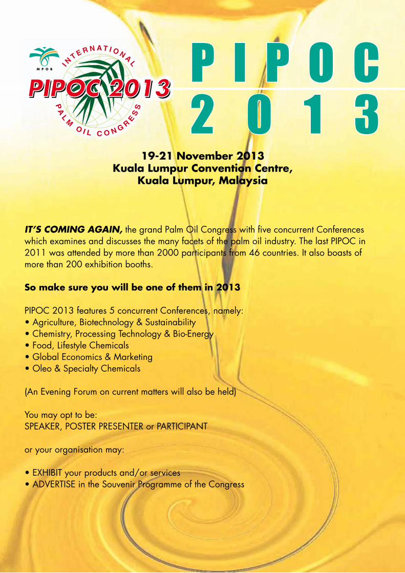
P I P O C2 0 1 3
19-21 November 2013Kuala Lumpur Convention Centre,
Kuala Lumpur, Malaysia
IT’S COMING AGAIN, the grand Palm Oil Congress with five concurrent Conferences which examines and discusses the many facets of the palm oil industry. The last PIPOC in 2011 was attended by more than 2000 participants from 46 countries. It also boasts of more than 200 exhibition booths.
So make sure you will be one of them in 2013
PIPOC 2013 features 5 concurrent Conferences, namely:• Agriculture, Biotechnology & Sustainability• Chemistry, Processing Technology & Bio-Energy• Food, Lifestyle Chemicals• Global Economics & Marketing• Oleo & Specialty Chemicals
(An Evening Forum on current matters will also be held)
You may opt to be:SPEAKER, POSTER PRESENTER or PARTICIPANT
or your organisation may:
• EXHIBIT your products and/or services• ADVERTISE in the Souvenir Programme of the Congress

PALM OIL ENGINEERING BULLETIN NO. 104 75
PIPOC 2011 was attended by more than 2000 participants from 46 countries.What better way to keep abreast with the rapid developments and changes in the oil palm industry
than to attend PIPOC 2013? This bi-annual Congress provides a platform that showcases the latest advances in the industry. It provides an excellent arena for networking and sharing information.
As a value-added feature, PIPOC 2013 boasts of an exhibition hall with a vast floor space of 2000 m2 that would house 200 booths. The new technologies and the information showcased here
would be a storehouse of knowledge and help you to increase the productivity and profitability of your business.
Technical On-site ToursVisiting plantations, oil palm mills, refineries, oleochemical plants and R&D facilities
Golf TournamentA special golf tournament will be organised for our golf enthusiasts.
…so hope to see you in PIPOC 2013!
Don’t forget to mark your calendar and extend our invitation to your friends and colleagues
Congress Registration Fee RM EUROParticipants1. Early bird (before 30 June 2013)2. Normal (after 30 June 2013)3. Poster Presenters and Students5% discount for group registration of 6 and more persons after the early bird period
2 3002 6001 300
600676350
MPOB Licensees 2 100 -Exhibition Fee varies with location 11 000
12 0002 8003 000
organised by:Malaysian Palm Oil Board (MPOB)MINISTRY OF PLANTATION INDUSTRIES AND COMMODITIES, MALAYSIA
For more information, please contact • [email protected]

PALM OIL ENGINEERING BULLETIN NO. 10476
Journal of Oil Palm Research
AVAILABLE ON-LINE
http://j
opr.mpob.gov.m
y
Vol. 24 April 2012
1
2007 Survey on Quality Parameters and Properties of Palm and Palm Kernel Fatty Acid DistillatesRM 20 (within Malaysia)/USD10 (outside Malaysia)
MPOBTECHNOLOGY
No. 33 • July 2010
2007 SURVEY ON QUALITY PARAMETERS AND PROPERTIES OF PALM AND PALM KERNEL FATTY
ACID DISTILLATES FROM LOCAL REFINERIES
by
BONNIE TAY YEN PING; TANG THIN SUE and MOHTAR YUSOF
i
Proof No: Date:Done By: Zack
OILPA L MB U L L E T I NNUMBER 63 HALF ANNUALLY NOVEMBER 2011
MPOBthe one stop
shopping centre for oil palm/palm oil
publications
Visit us at http://www.mpob.gov.my/
en/publications for the latest titles
MALAYSIAN PALM OIL BOARD6, Persiaran Institusi, Bandar Baru Bangi, 43000 Kajang, Selangor, Malaysia
Tel: 603-8769 4400Fax: 603-8922 3564
E-mail: [email protected]