engineered surfaces for mitigation of …this paper is declared a work of the u.s. government and is...
TRANSCRIPT

*This paper is declared a work of the U.S. Government and is not subject to copyright protection in the United States.
ENGINEERED SURFACES FOR MITIGATION OF INSECT RESIDUE ADHESION
Emilie J. Siochi1*, Joseph G. Smith Jr.1, Christopher J. Wohl1, John M. Gardner2, Ronald K.
Penner3 and John W. Connell1 1NASA Langley Research Center, Hampton, VA 23681 2National Institute of Aerospace, Hampton, VA 23666
3Science and Technology Corporation, Hampton, VA 23666
ABSTRACT
Maintenance of laminar flow under operational flight conditions is being investigated under NASA’s Environmentally Responsible Aviation (ERA) Program. Among the challenges with natural laminar flow is the accretion of residues from insect impacts incurred during takeoff or landing. Depending on air speed, temperature, and wing structure, the critical residue height for laminar flow disruption can be as low as 4 µm near the leading edge. In this study, engineered surfaces designed to minimize insect residue adhesion were examined. The coatings studied included chemical compositions containing functional groups typically associated with abhesive (non-stick) surfaces. To reduce surface contact by liquids and enhance abhesion, the engineered surfaces consisted of these coatings doped with particulate additives to generate random surface topography, as well as coatings applied to laser ablated surfaces having precision patterned topographies. Performance evaluation of these surfaces included contact angle goniometry of pristine coatings and profilometry of surfaces after insect impacts were incurred in laboratory scale tests, wind tunnel tests and flight tests. The results illustrate the complexity of designing antifouling surfaces for effective insect contamination mitigation under dynamic conditions and suggest that superhydrophobic surfaces may not be the most effective solution for preventing insect contamination on aircraft wing leading edges. *To whom correspondence should be addressed: [email protected], (757) 864-4279
1. INTRODUCTION
Drag reduction through maintenance of laminar flow over large areas on commercial transport sized aircraft can yield up to 30% improvement in fuel efficiency.1 While it is possible to minimize surface imperfections on critical portions of the aircraft where natural laminar flow (NLF) can be most beneficial during manufacture and maintenance of aircraft, operational flight conditions are more difficult to control. Among the challenges to practical application of NLF is the accretion of insect residue during takeoff and landing when the aircraft has to traverse altitudes where insect populations are present. Irregularities induced by residue left behind from insect impacts can cause premature transition from laminar to turbulent flow and reduce or negate the benefits offered by laminar flow designs. It has been documented that approximately 9% of all the insect strikes on the wing leading edge were of sufficient height to disrupt laminar flow at 7620 m (25,000 ft).2 The critical height at which turbulence is initiated can be as low as a few microns, depending on numerous factors including airfoil geometry and Reynolds number.
https://ntrs.nasa.gov/search.jsp?R=20130013855 2018-07-03T19:41:02+00:00Z

In 1960, Lachmann summarized methods that have been studied to mitigate insect residue adhesion.3 These methods were 1) natural erosion, 2) mechanical scrapers, 3) deflectors, 4) wing coverings, 5) soluble films, and 6) continuous liquid discharge. Since Lachmann’s publication, variations to these methods have been explored.4 More recently, Young and Humphreys reviewed insect residue adhesion mitigation approaches that were flight tested.5 The most promising mitigation strategies demonstrated on a Lockheed Jetstar aircraft flown under simulated airline service conditions were continuous liquid discharge and shielding via a Krueger-type leading edge device.6,7 The continuous liquid discharge approach was effective when the system was on continuously to keep the wing surface completely wetted. The Krueger shield effectively prevented insect residue deposition during takeoff; however, the shield was not deployed during landing when the heavy lift device was not required.6,7 Laminar flow can be achieved on the upper wing surfaces using this device, but physical discontinuities in the stowed configuration may induce early boundary layer transition on the lower surface. Hydrophobic coatings tested on sections of the Jetstar wing proved to be ineffective in maintaining the required surface characteristics for laminar flow.6,7 Elastic surfaces have also been investigated for the purpose of mitigating insect residue accretion.8,9 Coatings are desirable due to their ease of implementation on commercial aircraft, negligible weight penalty, environmental friendliness and relatively low cost. However, previous ground and flight tests have not identified any coatings that successfully mitigated insect residue adhesion.6,10,11 This study investigates the influence of coating composition on mitigating insect residue adhesion. To gain an understanding of the insect impact event and physical attributes of effective abhesive surfaces in operational environments, materials testing ranged from laboratory scale insect impact and wind tunnel tests to flight tests. Although flight tests have been conducted in the past to assess the viability of experimental coatings for insect residue adhesion mitigation, the authors are unaware of any previous studies that focused on establishing fundamental chemical and physical relationships between the coatings and insect residues in an effort to minimize interfacial interactions under realistic flight conditions. In addition to this ERA study,12 a similar effort known as AEROMUCO (AEROdynamic surfaces by advanced MUltifunctional COatings) is being conducted in the Europe Union. 13,14
2. EXPERIMENTAL
2.1 Materials
Aluminum (Al) 1100 alloy sheets approximately 51 and 76 µm in thickness were used for the lab scale tests and Basic Aerodynamic Research Tunnel (BART) studies respectively. Al/silicon (84/16) alloy sheets approximately 76 µm in thickness were used for the flight test. Prior to surface modification, the Al alloy substrates were cleaned with absolute ethanol using a dust-free laboratory cloth and air-dried at room temperature. Hexyltrimethoxysilane (Si-C6), dodecyltriethoxysilane (Si-C12), n-octadecyltriethoxysilane (Si-C18), and (heptadecafluoro-1,1,2,2-tetrahydrodecyl)triethoxysilane (Si-F17) were obtained from Gelest, Inc and used as-received. Aeroxide® LE2, a hydrophobic silicon dioxide with a Brunauer, Emmett and Teller (BET) surface area of 220 m2/g, was obtained from EVONIK Industries and used as-received. Molybdenum disulfide (MoS2, < 2 µm diameter) was obtained from Sigma Aldrich and used as-received. NyeBar® Type L (TAI Lubricants Inc.) was used as-received. 2,2-Bis(3,4-dicarboxyphenyl) hexafluoropropane (6FDA) was obtained from Clariant Corporation and
refluxed in acetic acid:acetic anhydride (3:1) for 24 h, isolated, and dried prior to use. 4,4’-Oxydianiline (4,4’-ODA) was obtained from Wakayama Seika Kogya Co. Ltd. and used as-received. The amine-terminated fluorinated alkyl ether (FAE) was synthesized from the hydroxyl-terminated oligomer15 purchased from Omnova. Spray coating of the various samples was performed using an airbrush (Badger Model 250) pressurized with dry air inside a paint booth. Flightless fruit flies were purchased from The Fruit Fly Shop located in San Diego, CA. Other materials were obtained from commercial sources and used as-received.
2.2 Surfaces Tested
2.2.1 Polymeric Particulate Composites
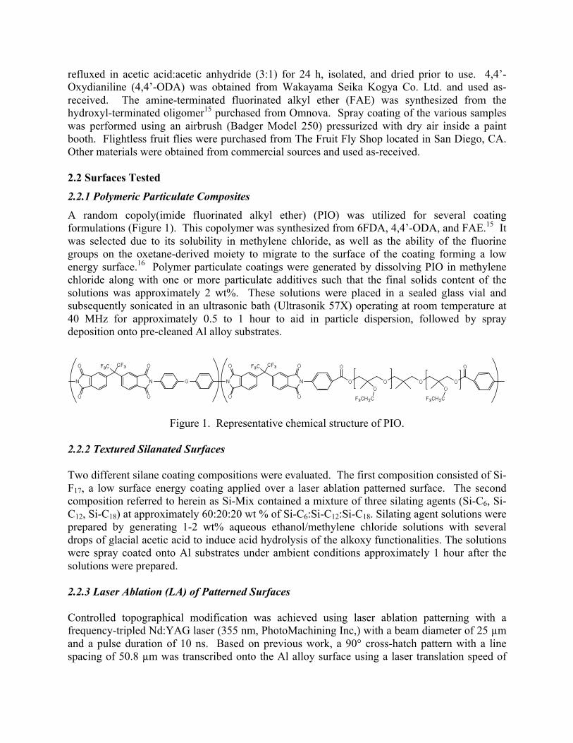
A random copoly(imide fluorinated alkyl ether) (PIO) was utilized for several coating formulations (Figure 1). This copolymer was synthesized from 6FDA, 4,4’-ODA, and FAE.15 It was selected due to its solubility in methylene chloride, as well as the ability of the fluorine groups on the oxetane-derived moiety to migrate to the surface of the coating forming a low energy surface.16 Polymer particulate coatings were generated by dissolving PIO in methylene chloride along with one or more particulate additives such that the final solids content of the solutions was approximately 2 wt%. These solutions were placed in a sealed glass vial and subsequently sonicated in an ultrasonic bath (Ultrasonik 57X) operating at room temperature at 40 MHz for approximately 0.5 to 1 hour to aid in particle dispersion, followed by spray deposition onto pre-cleaned Al alloy substrates.
2.2.2 Textured Silanated Surfaces Two different silane coating compositions were evaluated. The first composition consisted of Si-F17, a low surface energy coating applied over a laser ablation patterned surface. The second composition referred to herein as Si-Mix contained a mixture of three silating agents (Si-C6, Si-C12, Si-C18) at approximately 60:20:20 wt % of Si-C6:Si-C12:Si-C18. Silating agent solutions were prepared by generating 1-2 wt% aqueous ethanol/methylene chloride solutions with several drops of glacial acetic acid to induce acid hydrolysis of the alkoxy functionalities. The solutions were spray coated onto Al substrates under ambient conditions approximately 1 hour after the solutions were prepared. 2.2.3 Laser Ablation (LA) of Patterned Surfaces Controlled topographical modification was achieved using laser ablation patterning with a frequency-tripled Nd:YAG laser (355 nm, PhotoMachining Inc,) with a beam diameter of 25 µm and a pulse duration of 10 ns. Based on previous work, a 90° cross-hatch pattern with a line spacing of 50.8 µm was transcribed onto the Al alloy surface using a laser translation speed of
Figure 1. Representative chemical structure of PIO.

25.4 cm s-1.16 The pulse energy was approximately 65 mJ pulse-1 at 80 kHz. Test surfaces were laser ablation patterned prior to any chemical modification. 2.3 Contact Angle Goniometry Surface energy of the coatings was characterized via contact angle goniometry using a First Ten Angstroms FTA 1000B goniometer at ambient conditions. Contact angles were measured for each sample using an 8 µL drop of either water or ethylene glycol, and a 2 µL drop of methylene iodide. For each liquid, interfacial tension measurements were made of a suspended drop prior to experimentation to verify liquid purity and precision of the focused image. Contact angles were determined by drop shape analysis. For all surfaces, contact angles were measured for a minimum of three droplets. Surface energies were determined using the regression line analysis method developed by Kaelble.17
2.4 Optical Profilometry Insect residue heights were characterized using a FRT of America optical surface profilometer (Microprof 100). Data were collected over the entire region containing visible insect residues at a resolution of 5 µm between data points and 40 µm line to line. Several processing steps were performed on the collected topographical data including: segmentation to remove false zero readings, fitting the baseline to a second-order polynomial, and masking any edge and surface defects. Areal coverage was determined using grain analysis that identified and summed all features above the lowest permissible data plane, typically 8-15 µm, as individual grains. The data plane threshold above the established baseline was necessary to sufficiently separate insect residue features from substrate anomalies.
2.5 Lab Scale Fruit Fly Tests
To emulate flight conditions under which insect impact events occur, controlled fruit fly impact studies were conducted inside a benchtop wind tunnel (Figure 2). The insect delivery device, described below, was utilized to propel the fruit fly at velocities representative of aircraft takeoff speeds.
Figure 2. Benchtop wind tunnel used for controlled fruit fly impact studies.

2.5.1 Insect Delivery Device Testing was conducted using a custom-built pneumatic insect delivery device (Figure 3) constructed from a VACCON HIGHVAC HVP series 300-Venturi vacuum pump that was modified with an extended delivery nozzle to enable accurate positioning of the insect impact site. An impingement angle normal to the test surface was utilized. All tubing had an inner diameter (I.D.) of 1.27 cm. A 1 cm long Teflon® tube protruded from the insect insertion port. Air pressure to propel the insects was supplied through a high-pressure air hose using house air at a pressure sufficient to emulate the speed of aircraft at takeoff and landing, approximately 240 km/h. A single insect was used per impact event. Coated Al alloy foils were mounted onto a ¼ scale model of a section of an aircraft wing, located approximately 2.6 cm from the delivery nozzle. Testing was conducted at ambient temperature (approximately 25°C) and about 50- 60% relative humidity. For each event, the airflow was turned on prior to feeding the insect into the insect insertion port. The suction force rapidly ejected the insect from the delivery port for impact on the test surface. After each impact event the airflow was maintained for an additional 5 s to simulate wind shear experienced during actual flight conditions. High-speed photography was obtained during impact events using a Vision Research Phantom 12 camera at a speed of 50,000 frames per second.
Figure 3. Custom designed pneumatic insect delivery device schematic. 2.5.2 Insect Velocity Measurement Velocity measurements were obtained from high-speed photography of the insect trajectory against a 6 cm grid with 0.5 cm graduations. The air pressure was approximately 620 MPa. High-speed photography was obtained as described above. Insect velocities were determined by dividing the distance by the time, determined from the frame count, required for the insect to traverse the set distance. The velocities were determined to be 234 ± 29 km/h; well above that requisite for rupture of a fruit fly exoskeleton, approximately 50 km/h.18 2.6 Basic Aerodynamic Research Tunnel (BART) Tests
The BART is a subsonic, atmospheric wind tunnel used to investigate the fundamental characteristics of complex flow fields and to acquire detailed data for the development and

validation of computational fluid dynamics (CFD) models and methods. The tunnel has a closed test section that is 0.711 m high, 1.016 m wide, and 3.048 m deep. The free stream velocity was set to 201 km/h at an angle of attack of 8° to achieve a Reynolds number of 1-2 x 10⁶. For more details about the BART facility consult the references.19,20 2.6.1 Swept Wing Model Description The swept wing model used in BART was designed to withstand approximately 845 N normal force on the wing. The objective was to evaluate insect impact and insect residue adhesion characteristics on various coatings under conditions that mimic takeoff and landing. The coatings were selected based on various criteria including contact angle measurements, knowledge of the surface chemistry/adhesive property relationships, and insect impact tests conducted in the small laboratory wind tunnel. The BART wind tunnel model parameters are given in Table 1 and a photograph of the model mounted in the wind tunnel is shown in Figure 4.
Table 1. Parameters for the BART swept wing model
NACA 0015 Span: 71.1 cm Chord: 61 cm Sweep: 27.5°
Angle of attack: 8-12° Reynolds Numbera 1-2 x10⁶
aReynolds number based on an angle of attack of 8° and a free stream velocity of 201 km/h.
Figure 4. Photograph of an Al alloy substrate secured to the swept wing model in BART.
2.6.2 Insect Delivery A custom-built insect injection device was used to deliver the insects into the air-stream (Figure 5). The device was linked to a trigger system that activated a high-speed video camera when

insects were detected in the air-stream. A 1.59 cm steel barrel introduced the insects into the air-stream. It was designed so that the barrel tip can be positioned to deliver the maximum number of strikes possible onto the airfoil surface. The tubing anchor block consisted of a modified Venturi pump (Vaccon HVP-300), which was necessary to prevent movement of critical tubing components on the device. A 0.625 cm I.D. Teflon® tube connected the tubing anchor block to a 0.556 cm I.D. glass tube (insect sensing area tube). The remainder of the distance between the insect sensing area tube and the barrel was covered using 1.27 cm I.D. polytetrafluoroethylene (PTFE) hose.
Figure 5. Schematic of the insect insertion device.
A fiber optic area sensor (OMRON E32-T16W) and high-speed amplifier (OMRON E3X-DA21-S) were used to detect the presence of an insect in the glass tube. A micro programmable logic controller (PLC) system (OMRON CP1L-L1) interfaced the sensor with the high-speed camera. When an insect was detected, the PLC sent a transistor-transistor logic (TTL) signal to the camera instructing it to save a predetermined number of frames before and after the trigger. To use the device, a number of insects were placed in a PTFE tube with one end connected to the insect insertion point and the other end blocked off. Once the wind tunnel was at speed, the tube was unblocked and the insects traveled through the insect delivery device via the airflow created by the pressure differential between the wind tunnel test section and ambient environment. In these experiments 15-25 insects were injected over the course of 10-30 s. The trajectory paths of the insects were recorded using high-speed videography captured using a Vision Research Phantom 12 camera at a speed of 50,000 frames per second.
The following description details how each experiment or “run” was conducted. Once the Al panel was attached to the swept wing, the tunnel fan was activated and allowed to reach the required speed. At this point, insect injection triggered the high-speed video camera recording.

After multiple insect impacts were verified by preliminary visual examination of the coated panel from outside the test chamber as well as the high-speed video recording, airflow was stopped and the tunnel chamber opened to allow close visual inspection of the impacted panel. The number of visible insect strikes and their respective positions (both span and chord location) on the coated Al substrate were recorded. The substrates were then carefully removed from the swept wing model and stored under ambient conditions. The impacted substrates were later characterized using optical profilometry to measure insect residue height and areal coverage. The nature of each insect strike was determined via review of the high-speed video collected during the impact events.
2.7 Flight Tests
Flight tests were conducted out of Camarillo Airport in Camarillo, Ventura County, CA. Test articles were mounted on the inboard section of the aircraft wing, with approximately 0.91 m visible to the video and photo instrumentation. The inboard 0.91 m test section was covered with 3 test panels, with each panel containing 3 sections. The center section was an uncoated control surface and 2 experimental compositions were sprayed over the section to the right and left of the control as depicted in Figure 6. Test articles were installed immediately prior to the test flight using aluminized adhesive tape around the article perimeter to minimize creasing, bending, and warping. Air pockets were removed using a hand-held plastic straight edge to ensure that the airflow over the test articles was as uniform as possible. After the test aircraft returned to the hangar at the Camarillo airport, the flight test team determined the number and position of insect impacts, as well as the residue height [using a hand-held optical micrometer (model 8400, J Chadwick Company, Monrovia, CA)] prior to test article removal.
Figure 6. Al alloy test article coating schematic.
3. RESULTS AND DISCUSSION
3.1 Materials
Table 2 lists the coating compositions and the set of tests to which the samples were subjected. The sample set shown in Table 2 is a subset of over 70 compositions that were formulated and tested. This set was extracted from the large sample set to convey some lessons learned in developing a materials solution for a long-standing aerodynamics challenge.

Table 2. Description of surfaces tested.
Coating ID Composition Tests Lab BART Flight
Control Uncoated Al alloy X X X A NyeBar® Type L X X B PIO/40% SiO2 X X C PIO/60% SiO2 X X D PIO/50 % MoS2 X X X E LA-Si-F17 X X F Si Mix
X X
3.2 Contact Angle Goniometry
Contact angle goniometry was used to determine coating surface energy with the results shown in Table 3.
Table 3. Contact Angle Goniometry Results
Surface Energy (mJ/m2)
γd γp γtotal
Sample Dispersive Polar Total Control 22.1 3.6 25.6
A 9 0.05 9.1 B 14.2 0.3 14.5 C 26.3 10.6 36.9 D 24.5 0.03 24.5 E --- --- --- F 18.8 2.1 20.9
With the exception of coating F, all the coatings contained fluorine groups that preferentially migrated to the surface and were expected to lower the surface energy with respect to the control. Coatings B, C, and D incorporated particulates into a PIO matrix to afford a random surface texture similar to a lotus leaf. The measured surface energies of these coatings suggest that the effect of particulate fillers is complex given that the γtotal of PIO was 21.1 mJ/m2. The high surface energy of C was unexpected since the advancing water contact angle was 163° compared to 112° on PIO. Due to the small specimen size of E the surface energy was not determined; however, it had a water contact angle of 166° indicating superhydrophobicity. The water contact angle and γtotal of Si-F17 on a non-textured surface was 110° and 11.3 mJ/m2, respectively. The silane mixture F contained three components of differing chain lengths. This composition was prepared to assess the impact of molecular level conformational variations on insect residue adhesion and resulted in a slight lowering of the surface energy relative to the control.

3.3 Lab Scale Fruit Fly Tests
Figure 7. Influence of coating composition on insect residue heights and areal coverages from
lab scale fruit fly tests.
Residue adhesion was characterized both by residue height since there is a critical height which initiates unfavorable turbulent flow, and areal coverage, since constrained residue spreading may increase the probability of the contamination shearing off during flight to maintain laminar flow. These profilometry results from the laboratory fruit fly tests are shown in a scatter plot in Figure 7. Error bars are not included. Because insect hemolymph is predominantly aqueous, it was hypothesized that superhydrophobic surfaces can mitigate insect residue adhesion. If surface energy were the sole factor that determined insect residue adhesion, the lowest residue height and areal coverage would have been expected from coating A. Yet, this surface retained insect residues with heights that were higher than that measured for the control surface. Coating F, an aliphatic coating with a surface energy approximately double of that of A exhibited a comparable residue height but lower areal coverage. This may be due to the molecular texture provided by the different chain lengths making up this composition. Coating E, which consists of a low surface energy coating deposited over a periodic surface texture exhibited a lower areal coverage than A but a higher residue height, implying that a periodic texture may be less effective than the random molecular texture of coating F. The efficacy of random surface textures was affirmed by coatings B, C, and D, which are all polyimide based coatings modified by doping with particulates. These compositions afforded some of the lowest residue heights and areal coverages compared to the control. If these lab tests results were taken alone, they would suggest that surface texture plays a role in preventing insect residue adhesion, perhaps akin to what is known about biological surfaces such as the lotus leaf, where surface topographical features reduce the areal contact of water and contributes to the superhydrophobic nature of this surface.
Control
A
B
C
D
E
F
0.0
20.0
40.0
60.0
80.0
100.0
120.0
0.00 0.20 0.40 0.60 0.80 1.00 1.20 1.40 1.60
Res
idue
Hei
ght, µ
m
Areal Coverage, mm2
A) NyeBar® Type LB) PIO/40% SiO2
C) PIO/60% SiO2
D) PIO/50 % MoS2
E) LA-Si-F17
F) Si Mix

3.4 BART Tests A number of coatings were tested in the BART where the insect impact conditions simulated operational flight conditions more closely than the benchtop wind tunnel did. Although the benchtop wind tunnel tests involved fruit flies being propelled towards the representative coated airfoil at operational velocities, the distance to the test surface was very short. Additionally, there were minimal wall effects on the airfoil in the BART. Shown in Figure 8 are data for two of the coatings that were tested in the BART along with the control. For comparison, the analogous lab scale test data are shown on the same plot to illustrate the correlation between the two test configurations. It is notable that relative to the lab scale tests, the BART test results showed lower residue height and areal coverage overall for all samples tested. However, similar trends were observed for both test configurations, i.e. untreated surfaces yielded greater areal coverage of insect residues than coated surfaces.
Figure 8. Insect residue characterization from BART Tests.
Although coating D exhibited a higher residue height than the control in the BART, areal coverage was substantially reduced. Residue height of coating B was less than half that observed in the lab wind tunnel test with a significant reduction in the areal coverage.
3.5 Flight Tests It was anticipated that actual flight tests would offer the opportunity to validate results collected from controlled experiments in the lab scale and BART tests, especially considering that the same type of fruit fly was used in both the lab scale and BART tests, while there was less control
Control
B
D
D B
Control
0
10
20
30
40
50
60
70
80
0 0.2 0.4 0.6 0.8 1 1.2 1.4
Res
idue
Hei
ght, µ
m
Areal Coverage, mm2
BART
Lab Wind Tunnel
B) PIO/40% SiO2
D) PIO/50 % MoS2

over the type of insects that can impact the surface during the flight tests. The selected engineered surfaces were mounted on the aircraft wing as shown in Figures 9A-E. The aircraft was flown under conditions to assure high probability of encountering insects during takeoff and landing. Because it was unlikely to obtain constant flight conditions throughout the duration of the scheduled flight tests, the flight experiments were designed so that there was always a control flown with the experimental test surfaces. The assumption was made that by flying the specimens in this manner, all surfaces had equal opportunity for insect strikes during the same flight, even as it was recognized that insect density was a variable from flight to flight.
Figure 9 shows the test panels still mounted onto the aircraft wing leading edge after the aircraft has landed. The paper strips seen in the photographs were used to mark the locations of insect impact residues, with each strip corresponding to a single insect strike. The number of insect residues collected on each surface was counted and averaged over the number of flights in which the engineered surface was flown. These average values and their standard deviations are listed in Table 4. It was encouraging to note that all test surfaces had fewer insect strikes than the control surfaces, although with only 3 flights possible for each set of samples, it was difficult to obtain statistically significant differences for several of the samples flown. Nevertheless, it is difficult to ignore the lower number of residues and lower residue heights obtained for Sample D relative to the control surface.
Figure 9. Image of the insect residues identified by visual inspection of the test
articles after flight for five test flights labeled from A to E.
Insect residue height is the critical parameter that determines whether laminar flow is maintained. The location of these residues along the wing chord is also important in determining
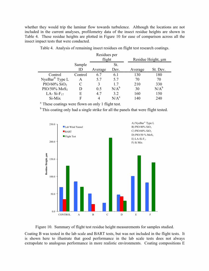
whether they would trip the laminar flow towards turbulence. Although the locations are not included in the current analyses, profilometry data of the insect residue heights are shown in Table 4. These residue heights are plotted in Figure 10 for ease of comparison across all the insect impact tests that were conducted.
Table 4. Analysis of remaining insect residues on flight test research coatings.
Residues per
flight
Residue Height, µm
Sample
ID Average St.
Dev.
Average St. Dev. Control Control 6.7 6.1 130 180
NyeBar® Type L A 5.7 5.7 70 70 PIO/60% SiO2 C 3 1.7 210 330 PIO/50% MoS2 D 0.5 N/Ab 30 N/Ab
LA- Si-F17 E 4.7 3.2 160 150 Si-Mix F 4 N/Aa 140 240
a These coatings were flown on only 1 flight test. b This coating only had a single strike for all the panels that were flight tested.
Figure 10. Summary of flight test residue height measurements for samples studied. Coating B was tested in the lab scale and BART tests, but was not included in the flight tests. It is shown here to illustrate that good performance in the lab scale tests does not always extrapolate to analogous performance in more realistic environments. Coating compositions E
0.0
50.0
100.0
150.0
200.0
250.0
CONTROL A B C D E F
Res
idue
Hei
ght, µ
m
Lab Wind Tunnel
BART
Flight Test
A) NyeBar® Type LB) PIO/40% SiO2
C) PIO/60% SiO2
D) PIO/50 % MoS2
E) LA-Si-F17
F) Si Mix

and F were consistently worse than the control in the lab tests and flight tests. Coating D yielded the best results across all test conditions. It had lower residue heights and areal coverage relative to the control in the lab scale fruit fly test. Although it retained slightly higher residue heights in the BART tests, these residues were confined to areas much smaller than those noted on the control. It performed very well in the limited flight tests, having collected the least number of insect strikes and the lowest residue heights.
Unexpected results were obtained for coatings A and C. In lab tests, coating A performed worse than the control, while C was substantially better. However, the flight test results were reversed for these two materials with coating C having significantly higher residue heights than the control. It is notable that there were far fewer residues counted on coating C relative to the control, even though the residues present from the flight tests were significantly taller than those measured on the control surface. Coating A appeared to perform well with regards to residue height, although it did not reduce insect residue count as well as the other coatings in this set. As noted above, the lab scale fruit fly tests and BART tests utilized fairly uniform sized insects of the same species, while the flight tests relied on the insect population available in the test zone. The flight tests were critical to evaluating the performance of engineered surfaces in realistic operational environments, even though data analysis was complicated by less control over the variables and limitations on the number of flights possible. Although the small number of flight tests yielded less than desirable statistical data, important lessons were learned both for design of engineered surfaces as well as future flight tests.
4. SUMMARY
The results presented herein provide some lessons learned in the design and evaluation of engineered surfaces for the mitigation of insect residue adhesion as applied to aircraft wing leading edges. Results from controlled experimental settings did not always correspond to those obtained under real operational conditions. Superhydrophobicity alone did not solve the insect contamination problem. Although insect hemolymph is largely aqueous, surface fouling appears to be due to the biological components that still adhered to surfaces shown to be highly hydrophobic by contact angle goniometry, albeit with controlled spreading as indicated by the reduced areal coverage noted on the coatings. Given the limited number of flight tests conducted, it was difficult to draw statistically significant conclusions, although the PIO based matrix doped with MoS2 appears to be a promising candidate for further investigation.
5. ACKNOWLEDGEMENTS
The Authors thank Dan Neuhart, Marlyn Andino, Donald Day and Paul Bagby of NASA LaRC for supporting the ground tests conducted. We also acknowledge Anne Bender, Christopher Harris, Andrea Korntheuer and Barry Hawkins of Northrup Grumman and Ben Harvey, Mark Stuckey, Phillip Grassa and John Marion of Scaled Composites who conducted the flight tests.
6. REFERENCES
[1] Joslin, R., "Aircraft Laminar Flow Control," Ann. Rev. Fluid Mech., 30, 1998, pp. 1-29. [2] Croom, C. C. and Holmes, B. J., "N88-14954," Langley Symposium on Aerodynamics,
1986. [3] Lachman, G. V., "Aspects of Insect Contamination in Relation to Laminar Flow Aircraft,"
A.R. C. Technical Report, C.P. No. 484, 1960.

[4] Maresh, J. L. and Bragg, M. B., "The Role of Airfoil Geometry in Minimizing the Effect of Insect Contamination of Laminar Flow Sections," AIAA 2nd Applied Aerodynamics Conference, Seattle, Washington, 1984.
[5] Young, T. and Humphreys, B., "Liquid Anti-Contamination Systems for Hybrid Laminar Control Flow Aircraft: A Review of Critical Issues and Important Experimental Results," Proc. Instn. Mech. Engrs. G. J. Aerospace Eng., 218, 2004, pp. 267-277.
[6] Fisher, D. F. and Peterson Jr., J. B., "Flight Experience on the Need and Use of Inflight Leading Edge Washing for a Laminar Flow Airfoil," AIAA Aircraft Systems and Technology Meeting, Los Angeles, CA, 1978.
[7] Wagner, R. D., Maddalon, D. V. and Fisher, D. F., "Laminar Flow Control Leading-Edge Systems in Simulated Airline Service," Journal of Aircraft, 27, 1990, pp. 239-244.
[8] Siochi, E., Eiss, N., Gilliam, D. and Wightman, J., "A Fundamental Study of the Sticking of Insect Residues to Aircraft Wings," J Colloid Interface Sci., 115, 1987, pp. 346-356.
[9] Wohl, C. J., Smith Jr, J. G., Penner, R. K., Lorenzi, T. M., Lovell, C. S. and Siochi, E. J., "Evaluation of Commercially Available Materials to Mitigate Insect Residue Adhesion on Wing Leading Edge Surfaces," Prog. Org. Coat., 76, 2013, pp. 42-50.
[10] Braslow, A. L. and Muraca, R. J., "A Perspective of Laminar Flow Control," AIAA, 1978. [11] Peterson Jr., J. B. and Fisher, D. F., "Flight Investigation of Insect Contamination and Its
Alleviation Ctol Transport Technology," National Aeronautics and Space Administration, NASA CP-2036, 1978.
[12] Wohl, C. J., Smith, J. G, Jr., Connell, J. W., Siochi, E. J., Penner, R., K. and Gardner, J. M., "Engineered Surfaces for Mitigation of Insect Residue Adhesion," 51st AIAA Aerospace Sciences Meeting, Grapevine, Texas, 2013.
[13] Young, T. M., Tobin, E. F. and Kok, M., "Laboratory Testing of Insect Contamination for Laminar Flow Applications using an Insect Impact Test Facility, ICAS 2012-3.4.4, 28th International Congress of the Aeronautical Sciences, Brisbane, Australia, September 28-30, 2012.
[14] http://www.aeromuco.eu [15] Wohl, C., Applin, S. I., Cooper, L. L. and Connell, J., "Copolyimide Surface Modifying
Agents for Particle Adhesion Mitigation," 242 ACS National Meeting, Denver, CO, 2011. [16] Wohl, C. J., Belcher, M. A., Chen, L. and Connell, J. W., "Laser Ablative Patterning of
Copoly(Imide Siloxane)S Generating Superhydrophobic Surfaces," Langmuir, 26, 2010, pp. 11469-11478.
[17] Kaelble, D. H., "Dispersion-Polar Surface Tension Properties of Organic Solids," J Adhes., 2,1970, pp. 66-81.
[18] Joslin, R., "Overview of Laminar Flow Control," National Aeronautics and Space Administration, NASA/TP-1998-208705, 1998.
[19] Sellers, W. L. and Kjelgaard, S. O., "The Basic Aerodynamics Research Tunnel-a Facility Dedicated to Code Validation," AIAA 88, 1997.
[20] Neuhart, D. H., Jenkins, L. N., Choudhari, M. M. and Khorrami, M. R., "Measurements of the Flowfield Interaction between Tandem Cylinders," AIAA, 2009.