engine f 33 a/b - milspecppg
TRANSCRIPT

GH F33 BDA
Göbler-Hirthmotoren KG
Service Manual
Engine
F 33 A/B
Göbler-Hirthmotoren KG, Max-Eyth-Str. 10, Germany-71726 BenningenTel.: 0049-7144-8551-0, Fax: 0049-7144-5415
e-mail: [email protected], internet: www.hirth-engines.de
Stand: 02.02.05 DOC_F33_B_E_0.01

GH F33 BDA
Engine
Type F 33 A/B
Manual
Read the operating instructions completely before the assembly of the engine or before starting the engine.
In the interest of the ongoing developments of our products, we reserve the right to change the delivery volume in form, technique and supply. We also ask for your understanding that the data in this instruction manual gives no further claims.
Stand: 02.02.05 DOC_F33_B_E_0.01

GH F33 BDA
Chapter 0Index
Chapter Designation Side
1 Description of the engine, Installation and 1-9
Technical Data
1.1 Description 1-10
1.1.1 General description of the engine 1-10
1.1.2 Description of the fuel mixture system 2-10
1.1.2-1 Variable jet carburettor 2-10
1.1.2-2 Diaphragm carburettor 3-10
1.1.3 Description of the ignition system 3-10
1.2 Installation 4-10
1.2.1 Engine installation 4-10
1.2.2 Air supply of the engine 5-10
1.2.3 Fuel supply of the engine 5-10
1.2.3-1 F 33 A 5-10
1.2.3-2 F 33 B 6-10
1.2.4 Carburettor control 6-10
1.2.5 Adjustment of idle speed 6-10
1.2.6 Adjustment of the idle fuel mixture 7-10
1.2.7 Fixation of plug socket at hanging installation 7-10
1.2.8 Cut off of the ignition system 7-10
1.3 Supervising the engine 7-10
1.3.1 CHT (cylinder head temperature) 8-10
1.3.2 EGT (exhaust gas temperature) 8-10
1.3.3 Fuel pressure 9-10
1.4 Identification plate 9-10
1.5 Technical Data 9-10
1.6 Installation sketch 10-10
Stand: 02.02.05 DOC_F33_B_E_0.01

GH F33 BDA
2 Operation of the engine
1-3
2.1 Generally 1-3
2.2 Run in recommendation 1-3
2.3 First inspection 2-3
2.4 Start procedure 2-3
2.5 Operation conditions 3-3
2.6 Cut off of the engine 3-3
3 Maintenance 1-7
3.1 Generally 1-7
3.1.1 Index 1-7
3.1.2 Tools, special tools and torques 1-7
3.2 Maintenance intervals 1-7
3.2.1 Daily inspections 1-7
3.2.2 Inspection intervals 2-7
3.3 Component change 2-7
3.4 Maintenance instructions 3-7
3.4.1 Variable jet and diaphragm carburettor 3-7
3.4.1.1 Maintenance of the variable jet carburettor 3-7
3.4.1.1-1 Basic adjustment of fuel mixture screw 3-7
3.4.1.2 Maintenance of the diaphragm carburettor 3-7
3.4.2 Air filter 4-7
3.4.2.1 Installation and de-installation of the air filter 4-7
2.4.2.1 Air filter cleaning 4-7
3.4.3 Fuel line and pulse line 4-7
3.4.3.1 Fuel line check 4-7
3.4.3.2 Pulse line check 4-7
3.4.4 Spark plugs and plug sockets 4-7
3.4.4.1 Condition check of the plug socket 4-7
3.4.4.2 Installation and de-installation of the spark plug 4-7
3.4.4.3 Condition of the spark plug 5-7
3.4.5 Cylinder head 5-7
3.4.5.1 Installation and de-installation of the cylinder head 5-7
Stand: 02.02.05 DOC_F33_B_E_0.01

GH F33 BDA
3.4.5.2 Check of the cylinder head condition 5-7
3.5 Trouble shooting 6-7
3.5.1 Engine doesn’t start 6-7
3.5.2 Engine doesn’t run at idle speed 6-7
3.5.3 Less power and rough running 6-7
3.5.4 Engine doesn’t reach full power 7-7
3.5.5 Cylinder head temperature is to high 7-7
4 Wiring diagram ignition system 1-3
4.1 Wiring diagram single ignition system 1-3
4.2 Wiring diagram dual ignition system 1-3
4.3 Wiring diagram single ignition lighting system 2-3
4.4 Wiring diagram dual ignition lighting system 2-3
4.5 Wiring diagram single ignition lighting system with 3-3
electric starter
4.6 Wiring diagram dual ignition system with 3-3
Electric starter
Stand: 02.02.05 DOC_F33_B_E_0.01

GH F33 BDA
Chapter 1Description of the engine, installation and technical data
1.1 Description
1.1.1 General description of the engine
The engine F 33 A/B (Illus. 1.1.1-1 and 1.1.1-2) of Göbler-Hirth Engines Ltd. is an air-cooled diaphragm-controlled one-cylinder 2-stroke engine. The cylinders consist of an aluminium alloy with wear-resistant tread alloy. C is mounted to crankcase through stay bolt, pulley and hexagon head nut. The cylinder heads consists of a special non-melting aluminium alloy that resist in same temper / hardness in high temperatures. It will be screwed on cylinder-by-cylinder screws and pullies without using gasket. The piston consists of an aluminium alloy and is tighted by two piston rings against cylinder thread. The piston is tied with connecting rod by piston pin and needle bearing. The crankshaft consists of Chromoly steel (42CrMo4) and is mounted in two ball bearings. It concerns to a manufactured crankshaft. The output drive is conical and equipped with centric external thread for mounting a junction cone on output drive. The connecting rod is connected with/ linked to the crankshaft through a crankpin and a needle bearing. The crankcase consists of an aluminium alloy. It is constructed as an radial divided case and consists of ignition part and an output driving part.Six cylinder screws with locking ring tie it. It picks up the stator plate of the ignition system, on the side of ignition.
Illustration 1.1.1-1 (Engine F 33 A)
Stand: 02.02.05 DOC_F33_B_E_0.01

GH F33 BDA
Illustration 1.1.1-2 (Engine F 33 B)
1.1.2 Description of the fuel mixture system
1.1.2-1 Variable jet carburettor
The fuel mixture system (Illus. 1.1.2-1) of the engine F 33 A consists of a variable jet carburettor. The carburettor is linked with intake window and the inlet diaphragm of crankcase by a rubber flange. On this occasion the rubber flange is screwed with cylinder screws and locking discs and the carburettor is tightened by a clamp in the rubber flange.On the inlet side of carburettor is positioned a dry air filter which is tightened on the carburettor by a clamp.
Illustration 1.1.2-1 (Fuel mixture system with variable jet carburettor)
Stand: 02.02.05 DOC_F33_B_E_0.01

GH F33 BDA
1.1.2.2 Diaphragm carburettor
The fuel mixture system (picture 1.1.2-2) of the engine F33 B consists of a diaphragm carburettor. The carburettor is linked with intake window and the inlet diaphragm of crankcase by an aluminium flange. In this occasion the aluminium flange is screwed by cylinder screws and locking discs at the cylinder and the carburettor is fixed at the aluminium flange by insulated part. On the inlet side of carburettor is positioned a dry air filter which is tightened on the carburettor by a clamp.
Illustration 1.1.2-2 (Fuel mixture system with diaphragm carburettor)
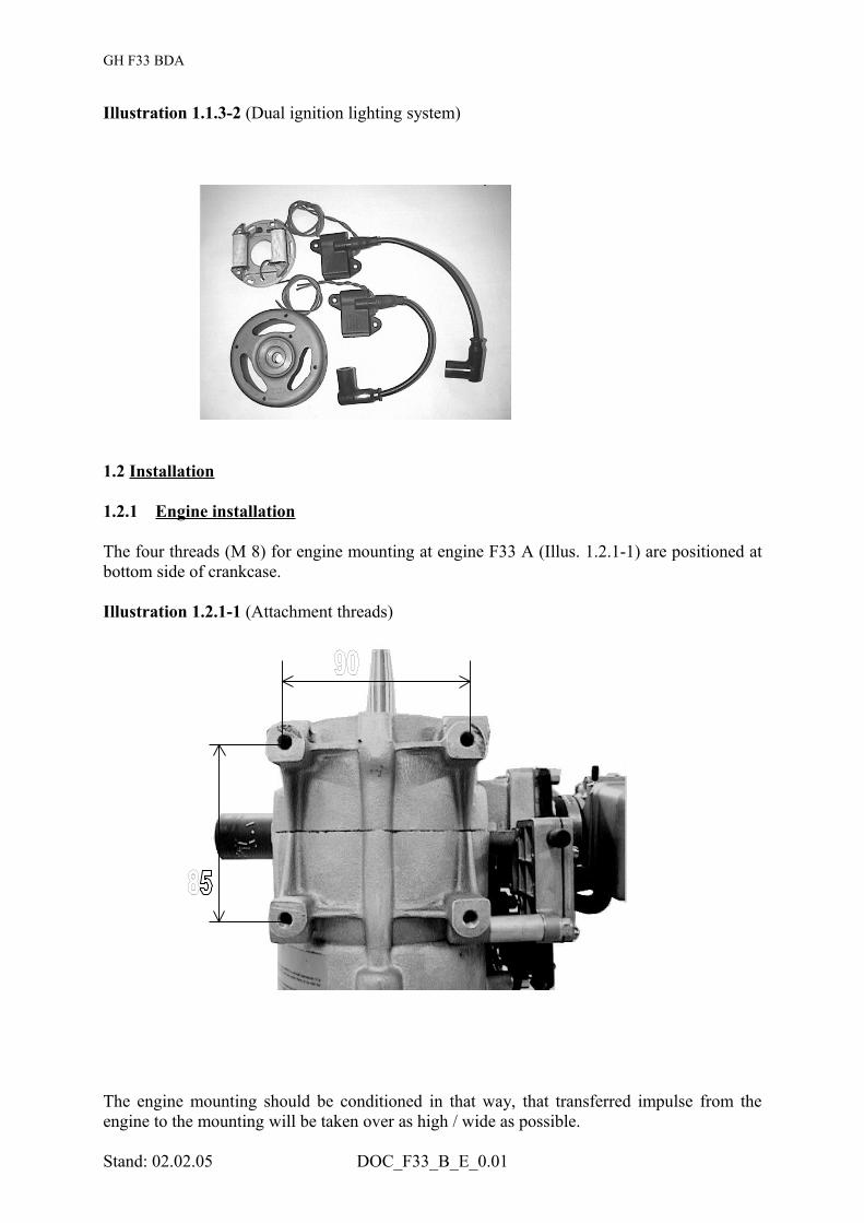
1.1.3 Description of the ignition system
The ignition system (Illus. 1.1.3-1, 1.1.3-2) is available as single and dual ignition. It consists of stator plate, flywheel, one ignition coil for single ignition, two ignition coils for dual ignition and ignition cables with spark plug connectors. The ignition system is all electronic. Generator power at 50 W is available on request.The stator plate is screwed with the crankcase on the ignition side. The flywheel is located on the crankshaft and surrounds stator plate. Intermediate case covers the flywheel of the ignition system. Ignition coil is / ignition coils are positioned at the crankcase.
Illustration 1.1.3-1 (Single ignition system)
Stand: 02.02.05 DOC_F33_B_E_0.01
GH F33 BDA
Illustration 1.1.3-2 (Dual ignition lighting system)
1.2 Installation
1.2.1 Engine installation
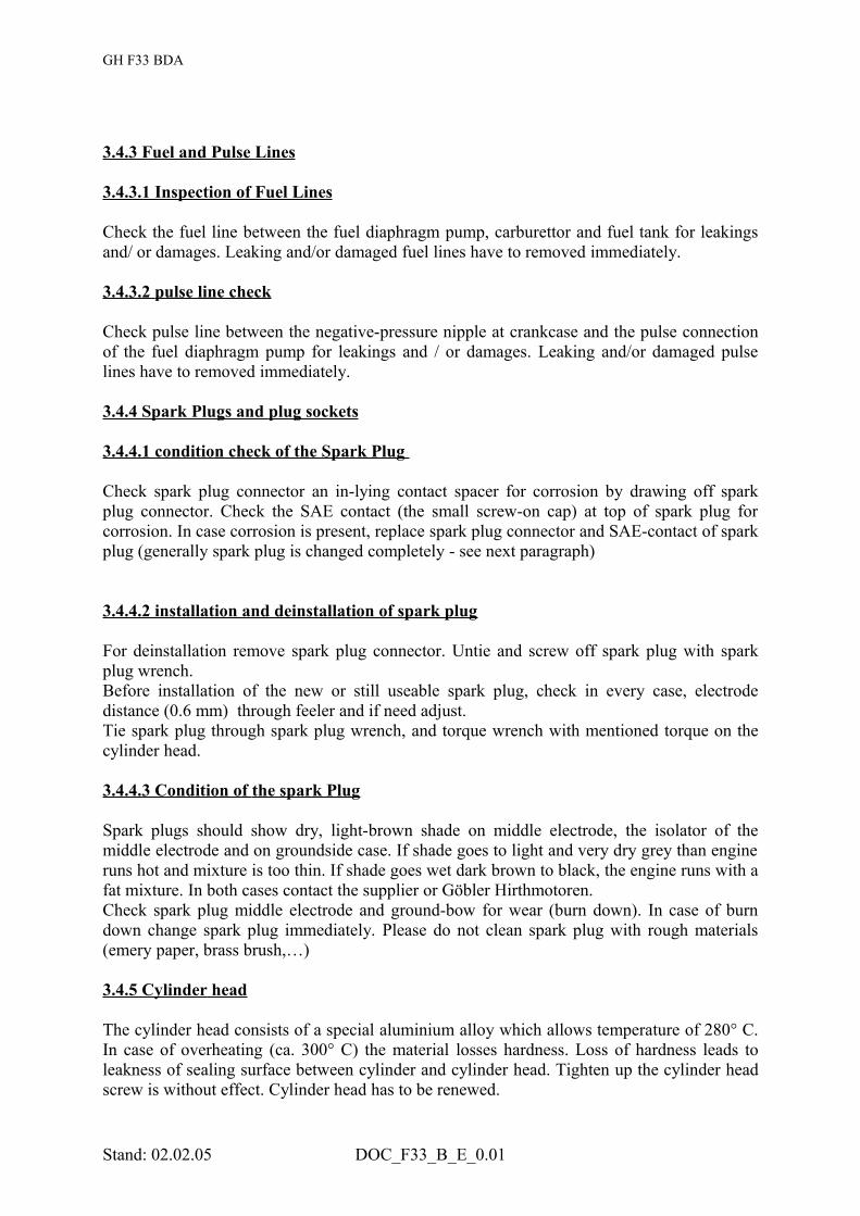
The four threads (M 8) for engine mounting at engine F33 A (Illus. 1.2.1-1) are positioned at bottom side of crankcase.
Illustration 1.2.1-1 (Attachment threads)
The engine mounting should be conditioned in that way, that transferred impulse from the engine to the mounting will be taken over as high / wide as possible.
Stand: 02.02.05 DOC_F33_B_E_0.01

GH F33 BDA
The damping of the mounting should be chosen as hard as possible, because engine could sway/ swing itself with damped mounting which is too smooth. This leads to problems with the fuel mixture (i.e. foam up of the fuel, uncontrolled centrifuge of the fuel pump diaphragm) and so to an unsafe running of the engine. -Recommendation for fixing:
Engine is mounted on a stabile fixing plate that is nearly doubled as the bottom side of the engine (the bigger the better). At the two exterior of the fixing plate there will be fixed, in axial way, four hard rubber damping elements (on each side two elements. This complete base will be fixed by these rubber damping elements on an according ground plate that is connected strong with the instrument.
1.2.2 Air supply of the engine
The engine has to be installed in that way, that the supplied fresh air is sufficient for cooling and for the carburettor. For an enclosed installation it has to be ensured that hot exhausted cooling air is not supplied to carburettor, because this leads to drastic reduction of power. Also it has to be ensured that hot exhausted cooling air could escape from case without obstruction, because this leads automatically to an overheat of the engine and so to destruction of itself.Sufficient fresh air supply has to be attended.
1.2.3 Fuel supply of the engine
1.2.3-1 F 33 A
The fuel supply of the engine is supported by a diaphragm pump (Illus. 1.2.3-1), which pushed through crank case low pressure.
Illustration 1.2.3-1 (Diaphragm Fuel pump)
This diaphragm pump is situated inside fuel line between the fuel tank and carburettor. A fuel filter always should be mounted between the diaphragm pump and fuel tank. The diaphragm pump is tied at crankcase.
Stand: 02.02.05 DOC_F33_B_E_0.01

GH F33 BDA
Pay attention that in standing position of the diaphragm pump the outlet is at the top. Place fuel connecting piece is perceptible by marking (→)on the case. The centrically connection the diaphragm pump is an impulse connection. The impulse line from the crankcase to the diaphragm pump should be as short as possible. For selection of impulse and fuel line it should be noticed that inflexible lines that will not extend under pressure should be used. Impulse line should have a maximum length of 150 mm and not exceed a minimum inside diameter of 6 mm. In every case it is advantageous if fuel tank is positioned above the engine, as so there is guaranteed some pressure of the fuel supply. The use of diaphragm pump is recommended additionally. A suitable measure instrument should control fuel pressure in any case. For installation of fuel tank below the engine, the following geometrical dates should be noted.The maximum length intake manifold between fuel tank and diaphragm pump should not exceed 2000 mm at a minimum inside diameter of 6 mm. At this a altitude of 1 m has not to exceed. During the running the possible inclination of complete equipment has to be considered (ascent / down fly of fly equipments, uphill/ downhill with ground equipments,….)The maximum length of the pressure line should not exceed 500 mm at inside diameter of 6 mm. At this a maximum pressure altitude between diaphragm pump center and floater case center of the carburettor should not be exceed. If diaphragm pump should be installed at engine, it should be mounted this way that diaphragm is vertical to crankshaft axle (wear or ignition side). Herewith it is guaranteed that vibrations at crankshaft axle due to the engine not impair the action and function of the diaphragm pump due superimposition of the vibrations.
1.2.3-2 F 33 B
The fuel supply of engine F 33 B is completely provided by diaphragm carburettor. Inside the carburettor is integrated a diaphragm pump that provides carburettor with sufficient fuel every time.The diaphragm pump that is integrated in the case of diaphragm carburettor is connected with the crankcase by a connecting hose and so with pressure pulsation of the engine. Because of the existing pulsation, fuel is sucked from the fuel tank through a fuel filter. The carburettor extracts the needed volume of fuel that is provided by diaphragm pump concerning the adjusted idle and load. The rest is pumped back by a return line into fuel tank.
1.2.4 Carburettor control
The throttle slide control of variable jet as well as diaphragm carburettor is handled by bowden cables. At idle running (throttle slide is seated on screw for idle; screw for idle of idle stop throttle strike against idle stop) bowden cable should have some space so that throttle slide can reach idle position secured. At full throttle the slide has to release the whole cross section of carburettor
1.2.5 Adjustment of idle speed
Adjustment of idle speed should be done with warm engine. If engine runs up, adjust the wanted idle speed by twisting the screw for idle. Twisting clockwise rises idle speed, twisting anti-clockwise reduces idle speed. Screw for idle is fixed through a spring that prevents undesirable wrench of the adjusting screw.
Stand: 02.02.05 DOC_F33_B_E_0.01

GH F33 BDA
1.2.6 Adjustment of the idle fuel mixture
Screw for idle is adjusted by Göbler Hirthmotoren before delivery of the engine and should not be twisted. As standard the screw is opened with 1,5 rotations. For readjusting the screw, tie it clockwise till screw is tight/ fixed (only tie slight against resistance) then turn off the screw anti-clockwise with 1,5 rotations.
1.2.7 Fixation of plug socket at hanging installation
If engine is installed at hanging position, plug socket(s) should be fixed that way, that drop off or interruption of contact due to engine vibrations are prevented effectively (based or secured due to wires or something similar)
1.2.8 Cut off of the ignition system
Single Ignition:The interrupter of the ignition system has to be lay on ground (e.g. case) due to a switch. With connection to the ground, the ignition system will be cut off.Double Ignition:Both interrupters absolutely have to lay on separate ground switchers. This instruction has to be fulfilled absolutely, because if both ground cables will be laid together, one ignition circuit can break down. With connection to the ground, the ignition system will be cut off.
1.3 Supervising the engine
It is strongly recommended to check the cylinder head temperature, exhaust gas temperature, and the fuel pressure. The fundamental adjustment of the engine guarantees a function without problems under the provided mounting conditions. As Göbler Hirthmotoren does not inspect the building in of the engine, there could be given bad external conditions (cooling air supply to low deep mounted tank at climb/ go down/ up-hill/ down-hill), therefore it is essential for a secured engine running to check the cylinder head-, exhaust gas temperature and the fuel pressure.Due to improper mountings or changes at the engine without checking the cylinder head and exhaust gas temperature, the claim of guarantee or each warranty is expired. The maximum temperatures, stated by Göbler Hirthmotoren KG, are not allowed to exceed.
The equipment mentioned in table 1.3-1 can be ordered from Göbler Hirthmotoren KG.
Table 1.3-1
Designation NumberEGT-/CHT-Temperature-measurement spark plug 14 mm 029.33EGT-/CHT-Temperature-measurement spark plug 10 mm 029.34Fuel pressure measurement 029.20
Stand: 02.02.05 DOC_F33_B_E_0.01

GH F33 BDA
1.3.1 CHT (Cylinder head temperature)
Cylinder head temperature (see Table 1.5-1) is measured at fitting beneath the spark plug. Hereby a ring-shaped thermocouple element is screwed in beneath the spark plug. The positioning of the thermocouple element is very important. The connecting cable of the thermocouple element should be conducted upwards in the way that the cooling air does not blow at the connection from the cable to the ring-shaped measure element.Only calibrated measuring equipments should be used. It has to be concerned that subsequently lengthened measuring cable, between thermocouple element and measure instrument, could falsify measured value. Temperature measure instruments with subsequently lengthened measuring cable should be calibrated once more under mounting conditions. Defective or not correct working thermocouple elements, temperature indication and measuring cable has to be removed immediately. The maximum allowed cylinder head temperatures indicated by Göbler-Hirthmotoren referring to the mentioned mounting position as well as to the calibrated measure element in this range of temperature.
1.3.2 EGT (Exhaust gas temperature)
The exhaust gas temperature (see Table 1.5-1) is measured at outlet manifold. Hereby a rod-shaped thermocouple element is clamped into a special sealed screwed joint. The positioning of the thermocouple element is very important. The thermocouple element should be inserted into the outlet manifold as deep as the peak of the thermocouple element is in the middle of the outlet pipe/ tube. The gap between piston rim at the outlet and the measuring peak runs to 110 mm.Only calibrated measuring equipments should be used. It has to be concerned that subsequently lengthened measuring cable, between thermocouple element and measure instrument, could falsify measured value.Temperature measure instruments with subsequently lengthened measuring cable should be calibrated once more under mounting conditions.Defective or not correct working thermocouple elements, temperature indication and measuring cable has to be removed immediately. The maximum allowed exhaust gas temperatures by Göbler-Hirthmotoren referring to the mentioned mounting position as well as to the calibrated measure element in this range of temperature.
1.3.3 Fuel pressure
(see table 1.5-1)
1.4 Identification plate
The identification plate is attached on ignition side at the upper side of the intermediate case. In any case of problems with your engine, then apply to Göbler Hirthmotoren KG with details of type and serial number of engine.
Stand: 02.02.05 DOC_F33_B_E_0.01

GH F33 BDA
Illustration 1.4-1 (Identification plate position)
1.5 Technical data
Table 1.5-1
Manufacturer Göbler-Hirthmotoren KGType F 33 AStroke Two strokeNumber of cylinders 1Displacement 313 cm3
Stroke 69 mmBore 76 mmCompression ratio 9,5 : 1Performance 18 kW (24,5 HP)RPM, max. 6500 1/minTurn direction Left, view to PTOStart device Recoil starter (Option: E-Starter in combination with G 33) Ignition system Electronic ignition system, single or dualGenerator 50 W, 12 V (Option)Spark plugs single ignition 023.22 (Hirth), B 8 HS (NGK), W 24 FS-U (N D)Spark plugs double ignition 023.26 (Hirth), C 8 HSA (NGK), U 24 FS-U (N D)Ignition timing 16° v. TDC (at 2000 1/min)Fuel mixture 1 Dellorto PHBE, 1 Mikuni BN34..., 1 air filter (try)Cooling Air cooled, free airOil/Fuel mixture 1 : 50Fuel 95 OctanTwo stroke oil Brand two stroke oilCHT max. 280° C / 536° FEGT max. 680° C / 1256° FFuel pressure min. 0,3 barEngine mass 12,7 kgExhaust system mass 3,4 kg
Stand: 02.02.05 DOC_F33_B_E_0.01

GH F33 BDA
1.6 Installation sketch
Stand: 02.02.05 DOC_F33_B_E_0.01
119
230
299,5131,5
85
M8 (4x)
74,5
209,6
380
82
90
70

GH F33 BDA
Chapter 2Operating of the Engine
2.1 General ly
The absolute attention of this chapter is essential for a long, economic and satisfactory operating of the engine.
- ONLY USE BRAND 2 STROKE-OIL AND THE PRESCRIBED FUEL (MIXTURE RATIO 1:50).
- PAY ATTENTION TO THE PRESCRIBED MIXTURE RATIO.
- REMOVE FUEL FROM THE FLOAT CHAMBERS OF THE CARBURETOR BOWLS AND THE TANK IN CASE THAT ENGINE DOES NOT RUN FOR A LONGER TIME. AFTER A LONGER STANDING TIME AND BEFORE START-UP ALL FUEL RESTS SHOULD BE REMOVED FROM THE FLOAT CHAMBERS OF THE CARBURETTOR AND FROM THE TANK.
- PAY ATTENTION THAT COOLING AND CABURETTOR ARE PROVIDED WITH SUFFICIENT FRESH AIR.
- PAY ATTENTION, THAT HOT COOLING AIR COULD BE RUN OFF WITHOUT OBSTRUCTION OR OTHER HINDRANCES.
- PAY ATTENTION THAT THE HOT AIR STREAM IS NOT SUCKED IN FROM THE CARBURETTOR.
- THE IGNITION SYSTEM HAS TO RUN ONLY WITH RESISTANCE SPARK PLUGS AND RESISTANCE SPARK PLUG CONNECTOR.
- ALWAYS ENGINE RUN/ WARM UP ITSELF.
2.2 run in recommendation
There are no special run in recommendations for the engines of Göbler Hirthmotoren KG because the nickel-silica alloy of the cylinder, the aluminium piston and the grey cast-iron of the piston rings do not have to run in one against the other. The engines are at full throttle from the moment of their mounting if maximum temperatures meet the recommendations as mentioned in chapter 1.As a recommendation for an adequate run in, engine should run at half throttle and half charge (not more then 4000 1/min) in the first of five hours of running. At the first run there could be a more intensify formation of smoke due to the fact that engine has 2-stroke-oil inside itself (because of the mounting).
2.3 First Inspection
After the first 10 – 15 hours of running or 10 – 15 hours after big inspection the following inspection works should be done
- Tighten up engine fixing screws for reasons of safety.
Stand: 02.02.05 DOC_F33_B_E_0.01

GH F33 BDA
- tighten up the cylinder head screws for reasons of safety
- tighten up the spark plugs for reasons of safety
- viewing examination (leaking, unassembled nuts/ screws,…)
Attention !
It is recommended to check the following items before every engine running for reasons of safety:
- Starter (checking of connections, fixings and condition; overhaul if necessary)
- Carburettor (checking of connections, fixings and condition; overhaul if necessary)
- Ignition system (checking connections, fixings and condition; overhaul if necessary))
- Cylinder head (checking of fixings and condition; overhaul if necessary)
- Cylinder (checking of fixings and condition; overhaul if necessary )
- Outlet manifold (checking of fixings and condition; overhaul if necessary)
- Exhaust system (checking of fixings and condition; overhaul if necessary)
- Spark plugs and spark plug connectors (checking of fixings and condition; overhaul if necessary)
- Fuel system (checking of leaking of soiled filters; overhaul if necessary)
2.3 Start Procedure
1. Ensure fuel providing (fill tank, open fuel cock,…)2. If engine is cold manipulate the choke. If engine is warm or hot do not manipulate the
choke. Choke lever in vertical position for a cold starting (in the case of hand lever-choke) 3. Set throttle hand lever in idling (slide in carburettor in idling)4. Ignition system put in running (ON-position of the short circuit button) 5. Start the engine (pull out the lever of the reverse starter till resistance is noticed, than pull
through strong and constant; manipulate electric starter for maximum of 10 seconds than break of 20)
6. If engine gets/ takes throttle, the choke could be taken back (checking by little open of them)
7. Engine has to run warm by ¼ weight/ charge or 3000 1/min ca. 3 minutes. 8. Engine has running temperature and is ready for running.
Notice:
If engine is mounted with a centrifugal clutch, for the run up it should be considered the following:
1. run up of engine in a speed range where centrifugal clutch is positioned in fixed gearing.
Stand: 02.02.05 DOC_F33_B_E_0.01

GH F33 BDA
2. run up of engine in a speed range where centrifugal clutch is positioned without fixed gearing. Because in this case the run up range is very slow, the time of run up should be longer.
Attention !
If the warm up or other engine operation is carried out in the range where the clutch engages, the result may be increased wear on the surface, glazing of the coating, or overheating of the clutch.
2.4 Operation conditions
During operation of the engine, cylinder head- and exhaust gas temperatures have to be controlled. If permissible maximum temperature of cylinder head and/ or exhaust are not exceed, engine can run without limit (also full load in maximum performance). It is also recommended to control fuel pressure during operation. Lack in fuel pressure can cause loss in performance and set out engine.
2.5 cut off the engine
Before engine is cut off, it should be run one minute at idle power in unencumbered state. This proceeding always should be noticed because an engine load tends to overheat when it is cut off after highest load.
Stand: 02.02.05 DOC_F33_B_E_0.01

GH F33 BDA
Chapter 3
Maintenance
3.1 Generally
3.1.1 Index
This chapter contains main instruction for technically qualified personnel to carry out minor inspections and repairs, such as:
- Periodical inspections of engine
- Maintenance of engine components
- Trouble shooting
3.1.2 Tools , special tools and torques
Description and sizes of tools are indicated in metrical system and can be purchased in special shops.
Tools:
Description Size Description SizeTorque wrench 0-50 Nm Hexagon head socket
wrenchSW 5
Engineers’ wrench SW 10 Engineers’ wrench SW 13Engineers’ wrench SW 17 Socket wrench SW 24Screwdriver Sparkplug wrench 20.6/20.8
Special tools:
Flywheel-withdraw W 85Piston ring clamp (piston – mounting assistance W 108/15
Initial Torque Values
Description Torques Description TorquesM6 9,6-11 Nm M8 23-28 NmM10 45-50 Nm
3.2 Maintenance Intervals
3.2.1 Daily Inspections
Daily inspection should be realized conscientious before every operation. Pay attention to following instructions:
Stand: 02.02.05 DOC_F33_B_E_0.01

GH F33 BDA
1. Air filter – checking of condition and bolting 2. Starter – checking of condition and bolting3. Ignition component – checking of condition, mounting and junction/ connection4. Crank case and cylinders – checking of leakage, condition and bolting 5. Spark plug connector – checking of condition and fit.
3.2.2 Inspection intervals
Basic unit assembly group Inspection intervalsEngine completeCheck for leaks (optical) Before every operationcheck for damages (optical) Before every operationCarburettorClean air filter Every 50hCheck carburettor setting Every 50hClean carburettor All 100hFuel systemClean fuel filter Every 50 hCheck fuel line and connections Every 25 hCheck impulse line to diaphragm pump Every 25 hIgnitionCheck ignition timing Every 100 hCheck electrode space of spark plugs Every 50 hExhaust systemCheck fixed positioning and damages Every 25 hCheck exhaust slot for trace of coke Every 100 h
3.3 change of component
Parts mentioned on table 3.3-1 should be replaced after indicated running hours. If wears appear earlier on this parts or other parts of the components, replace them accordingly. Please consult Göbler Hirthmotoren KG or any authorized dealer.
Table 3.3-1
Shortening SI means single ignition and shortening DI means dual ignition.
Description Order no. Running hoursSpark plug SI 023.22 100Spark plug DI 023.26 100Spark plug connector 024.22 200Short-firing cable 026.4/380 200Set of piston 014.81 1000Crankshaft F 331 A 1000Cylinder head SI F 332 E2 1000Cylinder head DI F 332 C3 1000Cylinder SI / Cylinder DI F 332 D1U / F332 B1U 1000Carburettor PHBE 34 BD/BS 1000Air filter 066.19 100
Stand: 02.02.05 DOC_F33_B_E_0.01

GH F33 BDA
Multiple dis valve 058.9 500
3.4 Maintenance Instructions
3.4.1 variable jet and diaphragm carburettor
Carburettor is jetted from Göbler Hirthmotoren so that thermical secured running is guaranteed. As interference on jets could lead to overheating and damage of engine, this should be left off. Only original spare parts should be used. Dates for carburettor can be obtained by Göbler-Hirthmotoren.
3.4.1.1 maintenance of the variable jet carburettor
open float chamber of carburettor every 50 hours of running and check for dirt. By occurrence of sedimentation, renew fuel filter between tank and diaphragm pump. Clean float case with fuel. Clean main and idle jet with fuel and blow through with compressed air. Do not use peaked or hard objects for cleaning the jets. Blow drillings and canals inside the carburettor with compressed air (more effective: cleaning with ultrasonic). Renew defective gaskets by original gaskets immediately.
3.4.1.1-1 basic adjustement of fuel mixture screw
The adjusting screw for idle in a slide carburettor is opened basically at 1,5 revolutions. Turn the adjusting screw for idle slightly against detent than open to 1,5 revolutions.
3.4.1.2 Maintenance of the diaphragm carburettor
Check carburettor for leakings. If there are leakings, change the gaskets according. Open side of jet of the carburettor (provided with a round bulge and a small drilling) every 100 hours of running. With this check inlayed diaphragm for damages and if need be renew it. Clean jets with fuel and blow them with compressed air. Blow through the canals inside carburettor likewise with compressed air. Likewise open the pumpside of the carburettor (with connecting nipples for fuel and nipples of pulse) and clean filter inset with fuel. Check diaphragm of pump membrane for damages and if need be change it.
3.4.2 Air Filter
3.4.2.1 Installation and deinstallation of air filter
For removing of the air filter untie the clamp at the air filter through screw driver and draw off the air filter from carburettor flange.For installation fix the air filter on the carburettor flange and tie it with clamp. If clamp is defected remove it immediately.
3.4.2.2 Cleaning the Air filters
Wash out the air filter with gasoline and dry it subsequently. To this blow through the filter from inside to outside by compressed air. Check filter for damage and renew filter if there is need for.
Stand: 02.02.05 DOC_F33_B_E_0.01
GH F33 BDA
3.4.3 Fuel and Pulse Lines
3.4.3.1 Inspection of Fuel Lines
Check the fuel line between the fuel diaphragm pump, carburettor and fuel tank for leakings and/ or damages. Leaking and/or damaged fuel lines have to removed immediately.
3.4.3.2 pulse line check
Check pulse line between the negative-pressure nipple at crankcase and the pulse connection of the fuel diaphragm pump for leakings and / or damages. Leaking and/or damaged pulse lines have to removed immediately.
3.4.4 Spark Plugs and plug sockets
3.4.4.1 condition check of the Spark Plug
Check spark plug connector an in-lying contact spacer for corrosion by drawing off spark plug connector. Check the SAE contact (the small screw-on cap) at top of spark plug for corrosion. In case corrosion is present, replace spark plug connector and SAE-contact of spark plug (generally spark plug is changed completely - see next paragraph)
3.4.4.2 installation and deinstallation of spark plug
For deinstallation remove spark plug connector. Untie and screw off spark plug with spark plug wrench.Before installation of the new or still useable spark plug, check in every case, electrode distance (0.6 mm) through feeler and if need adjust.Tie spark plug through spark plug wrench, and torque wrench with mentioned torque on the cylinder head.
3.4.4.3 Condition of the spark Plug Spark plugs should show dry, light-brown shade on middle electrode, the isolator of the middle electrode and on groundside case. If shade goes to light and very dry grey than engine runs hot and mixture is too thin. If shade goes wet dark brown to black, the engine runs with a fat mixture. In both cases contact the supplier or Göbler Hirthmotoren. Check spark plug middle electrode and ground-bow for wear (burn down). In case of burn down change spark plug immediately. Please do not clean spark plug with rough materials (emery paper, brass brush,…)
3.4.5 Cylinder head
The cylinder head consists of a special aluminium alloy which allows temperature of 280° C. In case of overheating (ca. 300° C) the material losses hardness. Loss of hardness leads to leakness of sealing surface between cylinder and cylinder head. Tighten up the cylinder head screw is without effect. Cylinder head has to be renewed.
Stand: 02.02.05 DOC_F33_B_E_0.01

GH F33 BDA
3.4.5.1 installation and deinstallation of cylinder head
For deinstallation of cylinder head, the spark plug connector and spark plug has to be removed as mentioned before. Untie and turn off the eight cylinder head – clamping bolt by hexagon head socket wrench. Mark position of the cylinder head. Take off cylinder head. For installation according reverse succession. First put on cylinder head – clamping bolt slightly than tie up crosswise with specified torque.
3.4.5.2 condition check of cylinder head
Check surface of cylinder head for spots where combustion gas is blown out. These spots can be detected due to black smear on sealing surface and combustion sediments on the cooling rib. Should there be such spots, renew cylinder head immediately. Check burning depression of cylinder head for combustion sediments (carbonization). If there is a strong sediment formation, remove carbon and change kind of oil possibly.
3.5 Trouble Shooting
3.5.1 Engine Does Not Start or is Difficult to Start
Cause: -Lack of fuelSolution: -check that fuel switch is on
-check that fuel filter is clean-check that fuel is in the tank
Cause: -Defective or discharged batterySolution: -Replace battery
-Charge the battery
Cause: - lack of compression in cylinder, caused by:
Cause: - loose spark plugSolution: -tight spark plug with alleged torque
Cause: - piston, piston ring, cylinder head, cylinder damagedSolution: -send engine to Göbler-Hirthmotoren or any authorized supplier
Cause: - lack of ignition spark or weak ignition spark
Cause: - spark plug damagedSolution: -renew spark plug
Cause: - spark plug connector damagedSolution: -renew spark plug connector
Cause: - ignition system damagedSolution: -send engine to Göbler-Hirthmotoren or any authorized supplier
Stand: 02.02.05 DOC_F33_B_E_0.01

GH F33 BDA
3.5.2 Engine does not run at idle speed
Cause : -Idle speed adjusted too lowSolution: -On the carburettor, screw the idle stop screw in
Cause: -Idle speed adjusted too highSolution: -On the carburetor, screw the idle stop screw out
Cause: -Idle running mixture adjusted wrongSolution: -Turn the low speed adjuster so that correct idle is insured
Cause: -ignition system damagedSolution: -send engine to Göbler-Hirthmotoren or authorized supplier
3.5.3 less power and rough running
Cause: -Dirty air filterSolution: -Clean or renew air filter
Cause: -Dirty or damaged spark plugSolution: -Clean or renew the spark plug
Cause: -Dirty fuel filterSolution: -Clean or renew fuel filter
Cause: -wrong (too oleiferous) mixture ratio of fuelSolution: -pour out tank and fill in prescribed fuel mixture
Cause: -spark plug connector damaged Solution: -renew the spark plug connector
3.5.4 Engine Does Not reach full power
Cause: -Dirty air filter Solution: - Clean or renew filter
Cause: -Dirty fuel filterSolution: -Clean or renew the fuel filter
Cause: -wrong (too oleiferous) mixture ratio of fuelSolution: -pour out tank and fill in prescribed fuel mixture
Cause: -Incorrect adjustment of carburetors, butterfly valve not fully openSolution: -Adjust butterfly valve accordingly
Cause: -One of the two ignition circuit is damagedSolution: -Send engine to Göbler-Hirthmotoren or authorized supplier
Cause: - piston, piston ring, cylinder head, or cylinder damaged
Stand: 02.02.05 DOC_F33_B_E_0.01

GH F33 BDA
Solution: -Send engine to Göbler-Hirthmotoren or authorized Hirth supplier
Cause: -wrong ignition timingSolution: -adjust ignition timing
-send engine to Göbler-Hirthmotoren or authorized supplier
3.5.5 cylinder Head Temperature is too high
Cause: -engine gets less cooling airSolution: -arrange mounting so that engine gets sufficient and unhindered cool air
Cause: -Dirty carburettorSolution: -Clean carburettor
Stand: 02.02.05 DOC_F33_B_E_0.01

GH F33 BDA
Chapter 4Wiring diagram ignition system
The 6 following wiring diagrams are referring to single and dual ignition systems with and without generator coil, just as without and with electric starterAttention: Read also the Hirth Information 0065 „Additional Information on voltage supply and ignition system”
Stand: 02.02.05 DOC_F33_B_E_0.01

GH F33 BDA
Dieser Schaltplan versteht sich als Verlegungsvorschlag f Tag Name
This wiring diagram is to be considered as a proposal for wiring e Gezeichnet: 07.01.99 RögeleLeitungsquerschnitt allgemein: 1,5 mm2 d Geprüft: 07.01.99 RögeleGeneral size of line wire: 1,5 mm2 c Schaltplan – Einfachzündung
b Wiring diagram – single ignitiona
Buchstabe Anzahl Änderung Tag Name F 33Rohteil-Nr. Maßstab Zeichnungs-Nr.
- - 14 A 135
Stand: 02.02.05 DOC_F33_B_E_0.01
Mass e - Gehäus eGround - C as e
Schalter
Switch
020.39/1020.39/2
ZündungIgn ition
rot
red
s c hwarzb lac k
braun
brown
Zündk erze
Spark p lug
023.22D
Zünds puleIgn ition c o il
020.39/3
r otred

GH F33 BDA
Stand: 02.02.05 DOC_F33_B_E_0.01
Mas s e - Gehäus eGr ound - C as e
Schalter
Switch
ZündungIgnition
F 334 B1U020.39 /2
rot
red
s c hw arzb lac k
braun
brown
braun
brown
Zündkerze
Spark p lug
023.26D
Zündkerze
Spark p lug
023.26D
Zünds puleIgn ition c o il
020.39 /3
r otred
Zünds pu leIgn ition c o il
020.39 /3

GH F33 BDADieser Schaltplan versteht sich als Verlegungsvorschlag f Tag Name
This wiring diagram is to be considered as a proposal for wiring e Gezeichnet: 07.01.99 RögeleLeitungsquerschnitt allgemein: 1,5 mm2 d Geprüft: 07.01.99 RögeleGeneral size of line wire: 1,5 mm2 c Schaltplan – Doppelzündung
b Wiring diagram – dual ignitiona
Buchstabe Anzahl Änderung Tag Name F 33Rohteil-Nr. Maßstab Zeichnungs-Nr.
- - 14 A 136
Stand: 02.02.05 DOC_F33_B_E_0.01
s c hw arzb lac k
Sicherung
Fus e
R eg le r -Gle ic h r ic hte rR ec tifie r -R egu lato r029 .5
rot
red
Mas s e - Gehäus eGround - C as e
braun
brown
Schalter
Switch
gelb-rot
y ellow-red
g e lby e llow
ge lby e llow
+
5 A
ZündungIgn ition
021 .39 /1020 .39 /2
braun
brown
rot
red
Zündk erze
Spark p lug
023 .22D
Zünds pu leIgn ition c o il
020 .39 /3
r otred
gelb-rotyellow-red
gelbyellow

GH F33 BDA
Dieser Schaltplan versteht sich als Verlegungsvorschlag f Tag NameThis wiring diagram is to be considered as a proposal for wiring e Gezeichnet: 07.01.99 RögeleLeitungsquerschnitt allgemein: 1,5 mm2 d Geprüft: 07.01.99 RögeleGeneral size of line wire: 1,5 mm2 c Schaltplan – EZ mit Generatorspule
b Wiring diagram – SI with generator coila
Buchstabe Anzahl Änderung Tag Name F 33Rohteil-Nr. Maßstab Zeichnungs-Nr.
- - 14 A 137
Stand: 02.02.05 DOC_F33_B_E_0.01
SicherungFuse
5 A
Regler-GleichrichterRectifier-Regulator029.5
rotred
Masse - GehäuseGround - Case
braunbrown
Schalterswitch
gelbyellow
gelbyellow
schwarzblack
+
ZündungIgnition
F 334 D1U020.39/2 braun
brown
rotred
Zündkerzespark plug
023.26D braunbrown
ZündspuleIgnition coil
020.39/3
Zündkerzespark plug
023.26D
ZündspuleIgnition coil
020.39/3
rotred
gelb-rotyellow-red
gelbyellow

GH F33 BDA
Dieser Schaltplan versteht sich als Verlegungsvorschlag f Tag NameThis wiring diagram is to be considered as a proposal for wiring e Gezeichnet: 12.01.99 RögeleLeitungsquerschnitt allgemein: 1,5 mm2 d Geprüft: 12.01.99 RögeleGeneral size of line wire: 1,5 mm2 c Schaltplan – DZ mit Generatorspule
b Wiring diagram – DI with generator coila
Buchstabe Anzahl Änderung Tag Name F 33Rohteil-Nr.
Maßstab Zeichnungs-Nr.
- - 14 A 138
Stand: 02.02.05 DOC_F33_B_E_0.01
ZündungIgnition
rot
red
021.39/1020.29/2
Sicherung
Fuse
rot red
braun
brown
-
Batterie
battery
12 V
gelb-rot
yellow-red S
chalter
Switch
Regler-GleichrichterRectifier-Regulator029.5
gelbyellow
5 A
schwarzblack
gelbyellow
+
Gehäuse auf MasseCase to ground
braun
brown
Zündkerze
Spark plug
023.26D
ZündspuleIgnition coil
020.39/3
rotred
6,3 mm
SchalterSwitch
Startrelais032.20
E-Starter028.15
M
gelb-rotyellow-red
gelbyellow

GH F33 BDA
Dieser Schaltplan versteht sich als Verlegungsvorschlag f Tag Name
This wiring diagram is to be considered as a proposal for wiring e Gezeichnet: 12.01.99 RögeleLeitungsquerschnitt allgemein: 1,5 mm2 d Geprüft: 12.01.99 RögeleGeneral size of line wire: 1,5 mm2 c Schaltplan – EZ mit Gen.-spule + E-St.Leitungsquerschnitt von/zu E-Starter: 16 mm2 b Wiring diagram – SI with gen.-coil + E-St.Size of line from / to E-Starter: 16 mm2 a F 33
Buchstabe Anzahl Änderung Tag NameRohteil-Nr. Maßstab Zeichnungs-Nr.
- - 14 A 139
Stand: 02.02.05 DOC_F33_B_E_0.01
Sicherung
Fuse
gelbyellow
-gelb-rotyellow-red
braun
brown
Batterie
battery
12 V
Regler-GleichrichterRectifier-Regulator029.5
rot
red
5 A
grün-gelbgreen-yellow
Schalter
Switch
ZündungIgnition
F 334 D1U020.39/2
schwarzblack
gelbyellow
rot
red
+
SchalterSwitch
braun
brown
braun
brown
Zündkerze
Spark plug
023.26D
ZündspuleIgnition coil
020.39/3
rotred
Zündkerze
Spark plug
023.26D
ZündspuleIgnition coil
020.39/3
Gehäuse auf MasseCase to ground6,3 mm
Startrelais032.20
M
E-Starter028.15

GH F33 BDA
Dieser Schaltplan versteht sich als Verlegungsvorschlag f Tag Name
This wiring diagram is to be considered as a proposal for wiring e Gezeichnet: 12.01.99 RögeleLeitungsquerschnitt allgemein: 1,5 mm2 d Geprüft: 12.01.99 RögeleGeneral size of line wire: 1,5 mm2 c Schaltplan – DZ mit Gen.-spule + E-St.Leitungsquerschnitt von/zu E-Starter: 16 mm2 b Wiring diagram – DI with gen.-coil + E-St.Size of line from/to E-Starter: 16 mm2 a neu 14.05.03 T.F. F 33
Buchstabe Anzahl Änderung Tag NameRohteil-Nr. Maßstab
- -Zeichnungs-Nr.
14 A 140
Stand: 02.02.05 DOC_F33_B_E_0.01
gelbyellow