engg tbd - jan2008 - rasman technologies pvt ltd | ksb ... = 2900 rpm (50 hz) n = 1450 r.p.m. (50...
TRANSCRIPT
WKFI
Contents
Sr. no. Description Page no.
1 Range of application 1
2 Design 1
3 Operating data 13.1 Selection charts (50 Hz) 23.1.1 Selection charts (60 Hz) 33.2 Discharge limits 43.3 Minimum Flow Q min. 43.4 Efficiency reductions 53.4.1 Balancing line connection 63.5 Number of stages 7
4 Flange ratings 8
5 Bearing 85.1 Bearing sizes 85.2 Lubrication quantity 85.3 Lubrication quality 85.3.1 Oil quality / Oil change 85.4 Bearing temperature 8
6 Shaft sealing 96.1 Soft packed stuffing box 96.1.1 Type of executions 96.1.2 Stuffing box packing space 96.1.3 Packing sizes 96.1.4 Packing material 96.2 Mechanical seals 9
7 Prime Mover 107.1 Type of Drive 107.2 Reserve 10
8 Coupling 10
9 Material construction 10
10 Spare Parts 11
11 Design Data 1111.1 Weights 1111.1.1 Weights of complete pump (Kg.) 1111.1.2 Rotor weights (Kg.) 1111.1.3 Weight of individuals components 1111.2 Water filling capacity 1211.3 Polor moment of inertia (J) for water filled
pumps 1211.4 Forces & Moments 12
12 Efficiency derations 1212.1 Due to balancing leak-off 1212.2 Due to No. of stages 1212.3 Due to impeller material 1212.4 Due to turning down of impeller vanes 12
13 Dimensional drawing 13
14 Sectional drawing & List of components 14

WKFI
1
1. Range of applicationIndustrial and domestic water supply, sprinkler, pressureboosting condensate extraction, boiler feed water for smalland medium power stations, fire fighting and distant heatinginstallations.
2. DesignHorizontal, vertically split pump with single entry and single ormultistage. Casings are sealed with O-rings and held togetherby means of tie rods, pump feet are cast integral under thesuction and discharge casings. Discharge nozzle verticallyup the suction nozzle vertically up or on the right hand side / orleft hand side when seen from suction side.
3. Operating dataCapacity Q upto 38 m3/h (11 ltr/sec)
Total head H upto 630 m (at Q=0 and ρ=1 Kg/dm3)
Temperature t upto +2000C
Suction pressure Ps upto 25 bar
End pressure Pd upto 631) bar
Speed n upto 4000 rpm
1) The sum of suction pressure and head of zero flow pointmay not exceed the stipulated limit.
Standard Execution Other Execution
Industrial and domestic water supply, sprinkler, pressure boosting condensate extraction, boiler feed water forsmall and medium power stations, fire fighting and distant heating installations. The material of pump parts are notattached by pure medii, chemically or mechanically.
Solid contents < 150 ppm, abrasive particles < 15 ppm For higher values refer to works
Temp. of flow medium -100C to + 2000C (For fluctuations see below)
Supply frequency 50 C/s 60 C/s
Max. speed1500 rpm (4 pole) 1800 rpm (4 pole)3000 rpm (2 pole) 3600 rpm (2 pole)
Direction of rotation Clockwise when seen from driven end (suction side)
Nozzle orientationDischarge-Vert. up Discharge-Vert. upSuction-Hor. to right Suction-Vert. up
Foot position In general at the bottom
Suction Discharge
Flange C.I. DIN2533/16 DIN2535/40Executions DIN2535/40 ANSI or BS
GS c 25 --- DIN2535/40DIN2546/64
Ap
plic
atio
n R
ang
e

WKFI
2
Cold starting :
3.1 Selection charts
n = 2900 rpm (50 Hz) n = 1450 r.p.m. (50 Hz)
Pressure CasingC.I. GS c 25bar bar
Maximum suction pressure 25 25
Maximum pump end pressure For continuous operation 40 63
Q = 0, ρ = 1000 Kg/m3 For quick stop 48.4 76.2
Suction casing 45 45
Maximum permissible test pressure Discharge casing, Stage casting 60 80
Cooling cover 16 16
Maximum permissible stage With continuous operation 15 15
differential pressure With quick stop 17 17

WKFI
3
3.1.1 Selection charts
n = 3500 rpm (60 Hz) n = 1750 r.p.m. (60 Hz)

WKFI
4
3.2 Discharge limits
Recommended operating zoneMinimum flow : 50% of Qopt.Maximum flow : 120% of Qopt.
3.3 Minimum Flow Q min.
To avoid eveporation and fluctuations in the pump, a minimumflow is to ensured by means of Minimum Flow Installation (e.g.Schroedahl) or Standard bypass.
Attention : bypass piping should be provided in exceptionalcases, since deration of efficiency by 5-10 points is possible.
Minimum Flow Liquid Temperature 0C
0.15 -10 to +100
0.20 >100 to 150
0.25 >150 to 200
Q min. =Qnopt.
Dia. of orifice plate to bleed off the minimum flow through by pass.

WKFI
5
3.4 Efficiency reductions
Reductions due to quantity losses
The balancing water line causes an internal circulation in thepump, which is referred to as quantity loss and results in areduction of efficiency.
Example :
WKFI 40/14H = 400 mQ = 20 m3/hEfficiency curve = 62.5%Efficiency reduction = 5.4 percentage pointsEffective efficiency = 62.5 - 5.4 = 57.1If required, the further efficiency reduction to be considered as well.

WK
FI
6
3.4.1B
alancin
g lin
e con
nectio
n
161412108642
No. of stages
WKFI 40, 50
150502010102050150
Stage differential pressure in MWC
654321
SuctionCasing
Balancing liquid line connection stageSuctionCasing
Bleed of stage for circulation piping forthe discharge side Mechanical seal
Bleed off / Balancing liquid line connection stage
87654321
Selection Example :WKFI 50, 10 stages. Differential stage pressure20 MWC. Balancing liquid line connected to3rd stage and circulation line from 5th stage.
WKFI
7
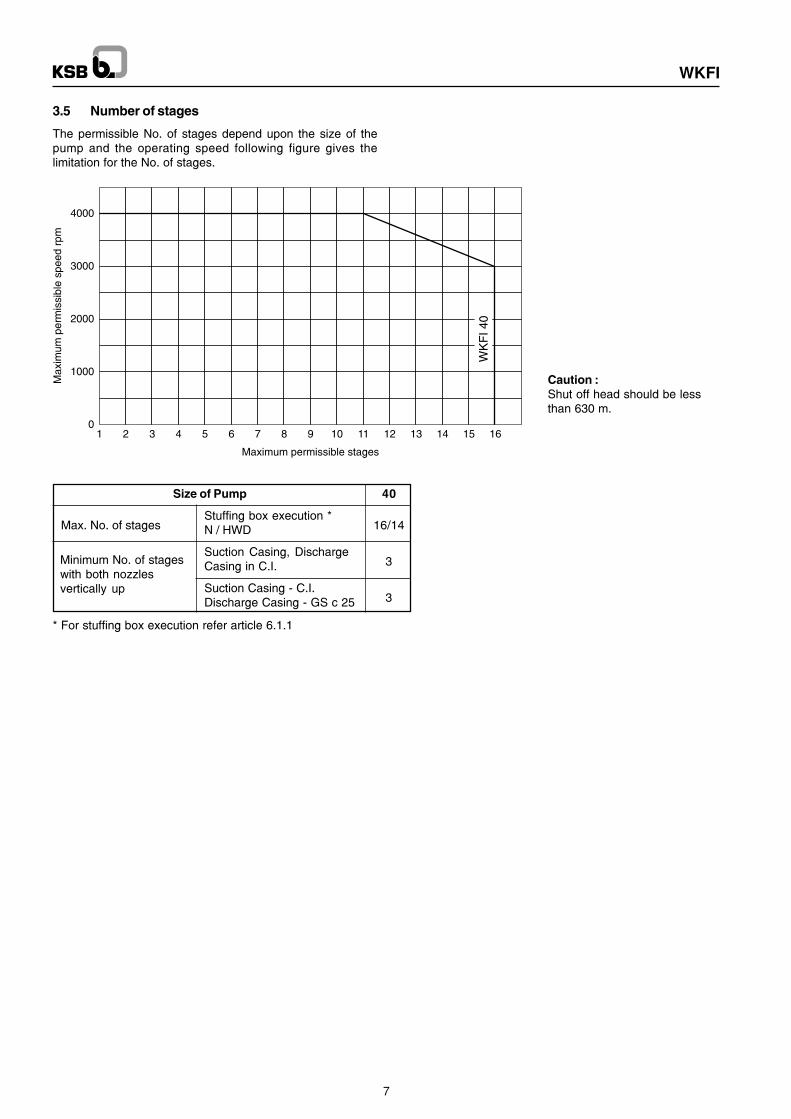
3.5 Number of stages
The permissible No. of stages depend upon the size of thepump and the operating speed following figure gives thelimitation for the No. of stages.
Caution :Shut off head should be lessthan 630 m.
Size of Pump 40
Max. No. of stagesStuffing box execution *
16/14N / HWD
Suction Casing, Discharge3Casing in C.I.
Suction Casing - C.I.3Discharge Casing - GS c 25
Minimum No. of stageswith both nozzlesvertically up
* For stuffing box execution refer article 6.1.1

WKFI
8
4. Flange ratingsFollowing table gives the maximum possible flange ratings.
5.1 Bearing sizes
5.2 Lubrication quantity
5.3 Lubrication quality
5.3.1 Oil quality / Oil change
Quality HD 20
The first oil change is to be taken up after 300 operating hours,and all further after every 3000 operating hours.
5.4 Bearing temperature
The bearing temperature may be upto 500C above roomtemperature, however should not exceed 900C (measuredexternally on the bearing housing).
Size 40
SuctionCI DIN 2535 / 40DIN
DischargeFlanges
Discharge GS c 25 DIN 2546 / 64
SuctionCI ANSI B 16.1 Class 250ANSI
DischargeFlanges
Discharge GS c 25 ANSI B 16.5 Class 400
SuctionCI BS10 Table HBS
DischargeFlanges
Discharge GS c 25 BS10 Table K
Fixed Bearing Loose BearingWKFI Ang. contact Cylindrical Roller Brg. with adaptor
ball brg. sleeveDIN 628 DIN 5412
40 2 x 7305 BUA NU 206 K C3
5. Bearing
Standard programme
Fixed and loose bearing, oil lubricated with sealing and ventwith constant level oiler.
Fig. 1 Bearing, oil lubricated
Constantlevel oiler
Short Oil lubricatedWKFI indication Oil per Brg.
~~ l.
40Fixed bearing 2 x 7305 BUA 0.18
Loose bearing NU 206 K C3 0.16
WKFI
9
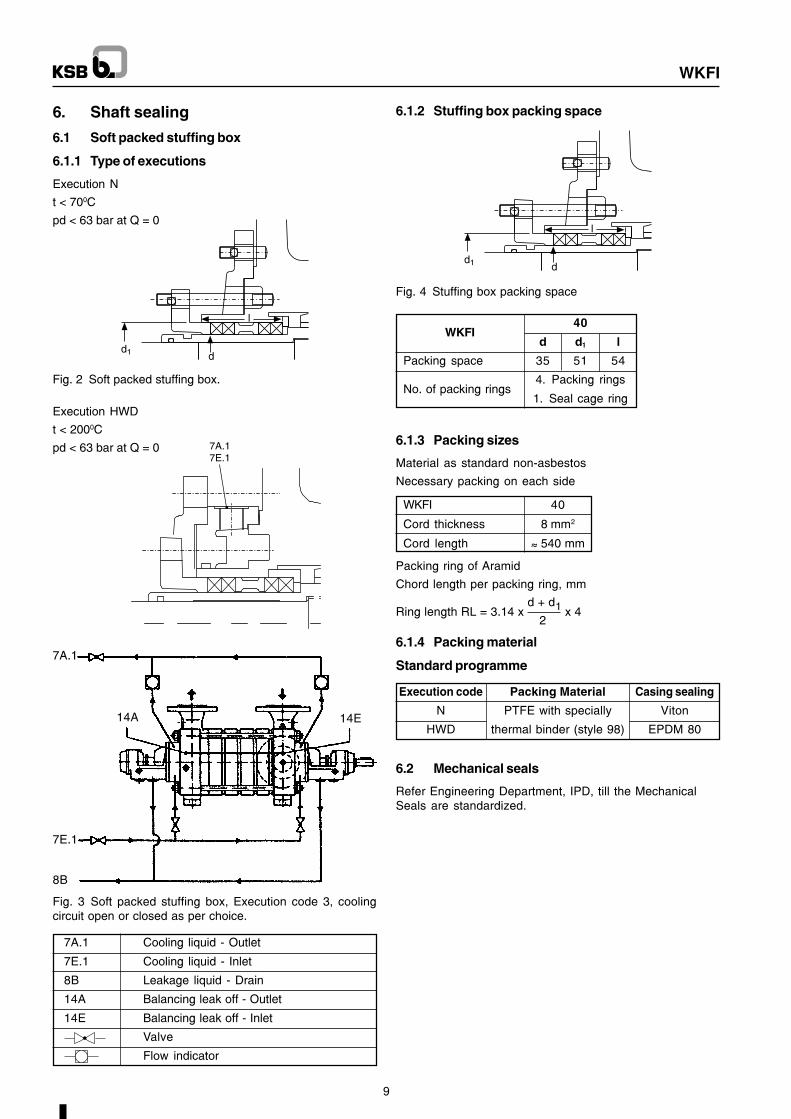
6. Shaft sealing
6.1 Soft packed stuffing box
6.1.1 Type of executions
Execution N
t < 700C
pd < 63 bar at Q = 0
Execution HWD
t < 2000C
pd < 63 bar at Q = 0
Fig. 2 Soft packed stuffing box.
7A.1
14A 14E
7E.1
8B
Fig. 3 Soft packed stuffing box, Execution code 3, coolingcircuit open or closed as per choice.
7A.1 Cooling liquid - Outlet
7E.1 Cooling liquid - Inlet
8B Leakage liquid - Drain
14A Balancing leak off - Outlet
14E Balancing leak off - Inlet
Valve
Flow indicator
6.1.2 Stuffing box packing space
Fig. 4 Stuffing box packing space
WKFI40
d d1 l
Packing space 35 51 54
No. of packing rings4. Packing rings
1. Seal cage ring
6.1.3 Packing sizes
Material as standard non-asbestos
Necessary packing on each side
WKFI 40
Cord thickness 8 mm2
Cord length ~~ 540 mm
6.1.4 Packing material
Standard programme
Execution code Packing Material Casing sealing
N PTFE with specially Viton
HWD thermal binder (style 98) EPDM 80
6.2 Mechanical seals
Refer Engineering Department, IPD, till the MechanicalSeals are standardized.
Packing ring of Aramid
Chord length per packing ring, mm
Ring length RL = 3.14 x d + d1
x 42
WKFI
10
7. Prime Mover
7.1 Type of drive
Directly through flexible coupling or indirectly through gearbox and elastic coupling; with electric motor, steam turbineor I C engine.
7.2 Reserve
Approximately 10% on the required power of the pump.
8. CouplingFlexible couplings of KSB make type BN or BZ-H, aregenerally used. Other couplings like Lovejoy, Metaflex etc.are possible, for which the case should be referred to H.O.
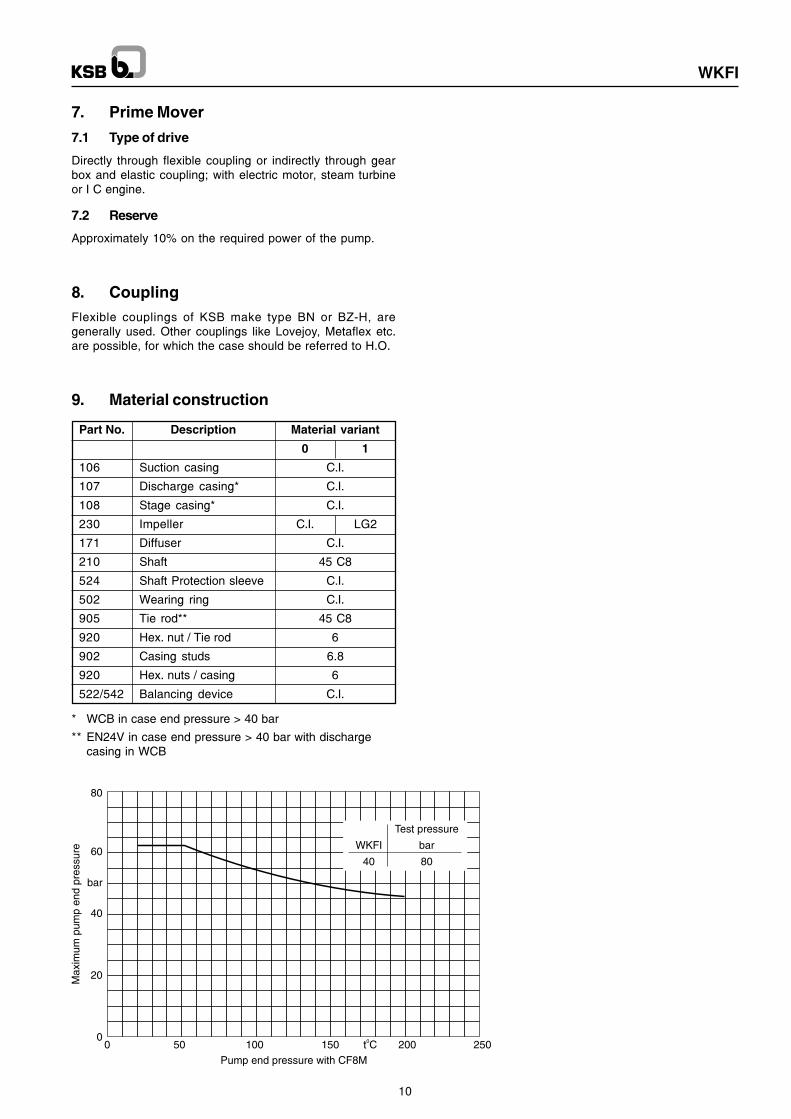
9. Material construction
* WCB in case end pressure > 40 bar
** EN24V in case end pressure > 40 bar with dischargecasing in WCB
Part No. Description Material variant
0 1
106 Suction casing C.I.
107 Discharge casing* C.I.
108 Stage casing* C.I.
230 Impeller C.I. LG2
171 Diffuser C.I.
210 Shaft 45 C8
524 Shaft Protection sleeve C.I.
502 Wearing ring C.I.
905 Tie rod** 45 C8
920 Hex. nut / Tie rod 6
902 Casing studs 6.8
920 Hex. nuts / casing 6
522/542 Balancing device C.I.

WKFI
11
10. Spare partsFollowing are the spare parts recommendations for 2 yearsoperation as per VDMA 24296.
No. of pumps including stand by pumps
Part No. Part Description2 3 4 5 6, 7 8, 9 10 or
more
Quantity of spare parts
210 Shaft with keys 1 1 2 2 2 3 30%
230 Impellers (set) 1 1 1 2 2 3 30%
320 Angular contact ball brg. (set) 1 1 2 2 3 4 50%
322 Cylindrical roller bearing 1 1 2 2 3 4 50%
411 Gasket 2 2 4 4 4 6 50%
412 O ring (sets) 4 6 8 8 9 12 150%
433 Complete mechanical seal 2 3 4 5 6 7 90%
461 Stuffing box packing 4 4 6 6 6 8 40%
502.1/.2 Wearing rings (2 x No. of stage) 2 2 2 3 3 4 50%
504 Distance ring 1 1 2 2 3 4 50%
542 Throttle bush 2 2 2 3 4 4 50%
523.1 Shaft sleeve 2 2 2 3 3 4 50%
524.1 Shaft protection sleeve 2 2 2 3 3 4 50%
505.1/.2 Spacer sleeve suc. / Discharge 2 2 2 3 3 4 50%
526 Centering bush 1 1 2 2 3 4 30%
522 Balancing drum 2 2 2 3 4 4 50%
551.1 Spacer washer (set) 1 1 2 2 3 4 50%
11. Design data
11.1 Weights
11.1.1 Weights of complete pump (Kg.)
WKFI 40
No. of stage
1 53
2 60
3 67
4 74
5 81
6 88
7 95
8 102
WKFI 40
No. of stage
9 109
10 116
11 123
12 130
13 137
14 144
15 151
16 158
11.1.2 Rotor weights (Kg.)
WKFI 40
Part No. Part Description
106 Suction casing 19
107 Discharge casing 20
108.1 Stage casing 3.7
171.1/.2 Diffuser 1.4
171.3 Diffuser last stage 0.9
210Single stage shaft 2.4
Shaft per stage 0.4
230.1/.2 Impeller 0.9
350.1 Bearing housing 2.6
360/361 Bearing cover 0.2
451 Stuffing box housing --
452 Stuffing box gland 0.3
502.1/.2 Wearing ring 0.05
524 Shaft protection sleeve 0.4
525.1 Spacer sleeve suction 0.1
525.2 Spacer sleeve discharge --
9054. Tie rods 1 stage 2.5
4. Tie rods per stage 0.5
11.1.3 Weights of individuals components
WKFI 40
Part Description
Impeller 1st stage 4.2
Per stageWith balancing drum -
Without balancing drum 1.3

WKFI
12
WKFI 40
No. of stage
1 2.5
2 3.5
3 4.4
4 5.3
5 6.3
6 7.2
7 8.1
8 9
WKFI 40
No. of stage
9 9.9
10 11
11 12
12 12.9
13 13.8
14 14.7
15 15.6
16 16.5
11.2 Water filling capacity (~ Lit.)
WKFI 40
No. of stage J (kgm2)
1 0.0039
2 0.0075
3 0.0111
4 0.0147
5 0.0183
6 0.0219
7 0.0255
8 0.0291
WKFI 40
No. of stage
9 0.0327
10 0.0363
11 0.0399
12 0.0435
13 0.0471
14 0.0507
15 0.0543
16 0.0579
11.3 Polor moment of inertia (J) for water filledpumps
DNMY
FY MX
MZ
FZ
FX
MY
FY
MZFX DNFZ
MX
11.4 Forces and moments
The following table gives the permissible forces andmoments, due to piping, on suction and discharge nozzles.The same are indicated in the figure on next page. Forcesand moments can act simultaneously on suction anddischarge nozzles.
FX = Horizontal parallel to the pump axis.Forces FY = Vertical to the pump axis.
FZ = Horizontal at right angle to the pump axis.
MX = about the horitontal axis parallel to thepump axis.
Moments MY = about the vertical nozzle axis.MZ = about the horitontal axis at right angle to
the pump axis.
Maximum permissible forces and moments onflanges :
WKFI 40
Suction casing
FX 600FY [N] 1400FZ 600
MX 400MY [Nm] 300MZ 400
WKFI 40
Discharge casing
FX 600FY [N] 1400FZ 600
MX 400MY [Nm] 300MZ 500
Y
Dischargeside
Suctionside
Z
X
Dowelling of the pump on the base frame
12. Efficiency derations
12.1 Due to balancing leak offRefer article 3.4
12.2 Due to No. of stages
No. of stages
1 2 3 4
WKFI Percentage points
40 -4 -3 -2 -1
12.3 Due to impeller material
The larger clearances at impellers of cast chromium steelresult in a larger balancing water quantity. Thereforeadditional efficiency reduction at
WKFI 40 - 2 percentage points
12.4 Due to turning down of impeller vanes
Design acc. to DIN 1944/III does not require a correction forturning down the impeller blades. Design acc. to DIN 1944/IIrequires the following efficiency reductions.
ηtot. at Q
Qopt.
ø Turning downPercentage points
ø Performance curve
0.5 1.0 1.2
0.98 -0.25 -0.5 -1
0.97 -0.5 -1 -2
0.96 -0.75 -1.5 -3
0.95 -1 -2 -4
0.94 -1.25 -2.5 -5
0.93 -1.5 -3 -6
0.92 -1.75 -3.5 -7
0.91 -2 -4 -8
0.90 -2.25 -4.5 -9

WKFI
13
WKFI DN1 DN2 a b d2 f h1 h2 l1 l2 l3 l4 l5 m2 n1 n2 d1 s t u
N HWD N HWD N HWD N HWD N HWD
40 50 40 185 60 16 264 293 140 185 60 194 223 215 244 169 198 190 219 50 300 250 24 20 27 8
NO. OF STAGES
01 02 03 04 05 06 07 08 09 10 11 12 13 14 15 16
e 80 135 185 235 285 335 385 435 485 535 585 635 685 735 785 835
m1 130 185 235 285 335 385 435 485 535 585 635 685 735 785 835 885
a
DN2
1M.1
DN1
1M.2
h1h2
s
b b
6B
n2
n1
d2
l3 e f
l2 l1
5B
7A.1 13D
14E
d1
u
t
d1k6
13B8B7E.1
m2
l4m1
m2
l5
14A
13B 8B 7E.1
13D 7A.1
13. Dimensional drawing
Connction Designation WKFI 40
1 M.1/.2 Pressure gauge G 1/2"
5 B Vent connection 1) G 1/4"
6 B Casing Drain G 1/4"
7 A.1/7 E.1 Cooling water outlet / inlet G 1/4"
8 B Leakage drain G 1/2"
13 B/13 D Oil drain / Topping up - venting G 1/8"
14 A / 14 E Balancing liquid outlet / inlet G 1/4"
1) If nozzle is at right hand side.

WKFI
14
14. Sectional drawing and list of components
Part No. Part designation
106 Suction casing107 Discharge casing108.01 Stage casing108.02 Stage casing171.01 Diffuser171.02 Diffuser / Last stage210 Shaft230.01 Impeller stage230.02 Impeller / Last stage320 Angl. cont. ball bearing322 Cylin. roller bearing350.01 Bearing housing / Suc.350.02 Bearing housing / Dis.360 Bearing cover361 Bearing cover400.02 Gasket411.01 V-Ring411.02 V-Ring412.01 O-Ring412.02 O-Ring412.04 O-Ring452 St. Box Housing458 Lantern ring461 Gland packing502 Wearing ring504 Spacer ring
920 526 350.01718
913461
902/920107
905920
550
940
902/920452 106 902/920
913718
400.02901
210
361901
931320
551504
731411
412.04524.1
458.01522
412.02171.02
542108
171230
412.01 502903
940524
452.01412.3
932411
731350
322531
360940
Part No. Part designation
522 Throttle sleeve524.01 Shaft prot. sleeve524.02 Shaft prot. sleeve526 Centering ring531 Adaptor sleeve542 Throttle bush550 Washer551 Spacer disc718 Socket731 Square head plug901 Hex. bolt902.01 Stud902.02 Stud903 Hex. head plug905 Tie rod913 Vent plug920.01 Hex. nut920.02 Hex. nut920.03 Hex. nut920.04 Slotted nut932 Circlip940.01 Key940.02 Key940.03 Key940.04 Key

WKFI
Notes