energy efficiency by using innovative bearing solutions · specialized multi-body simulation (mbs)...
TRANSCRIPT
powertransmissionengineering august 2010 www.powertransmission.com32
Management Summary Based on simulation methods and calculation tools developed by the Schaeffler Group and presented in the first
part of this paper, three approaches regarding increased efficiency based on rolling bearings are presented.The first approach addresses the overall bearing concept itself. It shows which bearing concept exhibits the highest
potential for reducing friction within the customer’s system.The second approach focuses on reducing the friction of the rolling bearing itself. In this respect, optimization of the
internal bearing geometry—as well as of the tribological conditions of relevant friction partners (e.g., roller face versus rib)—plays a key role. Examples used here are low-friction, tapered-roller and deep-groove ball bearings.
The third approach facilitates higher efficiency through downsizing. For example, the load-rating capacity of the Schaeffler Group’s new ball roller bearings is enhanced by their ability to place a higher number of rolling elements into the bearing without increasing its size.
IntroductionRolling bearings and saving energy go hand-in-hand.
In other words, the original purpose of a rolling bearing is to save energy by reducing the friction between mechani-cal parts in movement against each other—be it the rota-tion of a wind turbine, the wheel of a car or the shafts of a transmission. Accordingly, the rolling bearing is a key machine element with respect to the improvement of energy efficiency of a machine or system. In order to meet growing market demands in this field, the Schaeffler Group develops and manufactures low-friction bearing solutions. Schaeffler’s engineering expertise in this respect is based on simulation and calculation tools, understanding and analyzing the cus-tomer’s bearing-related system as a whole, as well as providing appropriate low-friction bearing components.
Analytical Model for Calculating and Minimizing Friction of Rolling Bearings
There are currently two methods for calculating the fric-tion of rolling bearings.
The first approach is to use the catalog method of the rolling bearing manufacturer and the second is to use highly specialized multi-body simulation (MBS) programs. The catalog method involves the use of empirical approaches. They enable the frictional torque to be calculated quickly for low model accuracy. On the other hand, MBS programs such as the CABA3D (Ref. 1), developed by the Schaeffler Group, have a very high model accuracy that require longer calcula-tion times.
In order to combine the advantages of the catalog method and the MBS programs, the Schaeffler Group has developed
Energy Efficiency BY USING
INNOVATIVE BEARING SOLUTIONSClaus Müller, Peter Schuster and Oliver Koch
a new analytical model for calculating rolling bearing friction. This model was implemented in the BEARINX (Ref. 2) pro-gram so that the new friction calculation is available to a large group of users. Advantages are short calculation times and the consideration of various influencing factors such as real stress distribution and the internal geometry of the bearing. Furthermore, the rolling bearing power loss of entire shaft systems or transmissions can be calculated, as well as load distribution and rating life. Thus it is possible to select an (friction) optimized bearing design, even in the early product development phase.
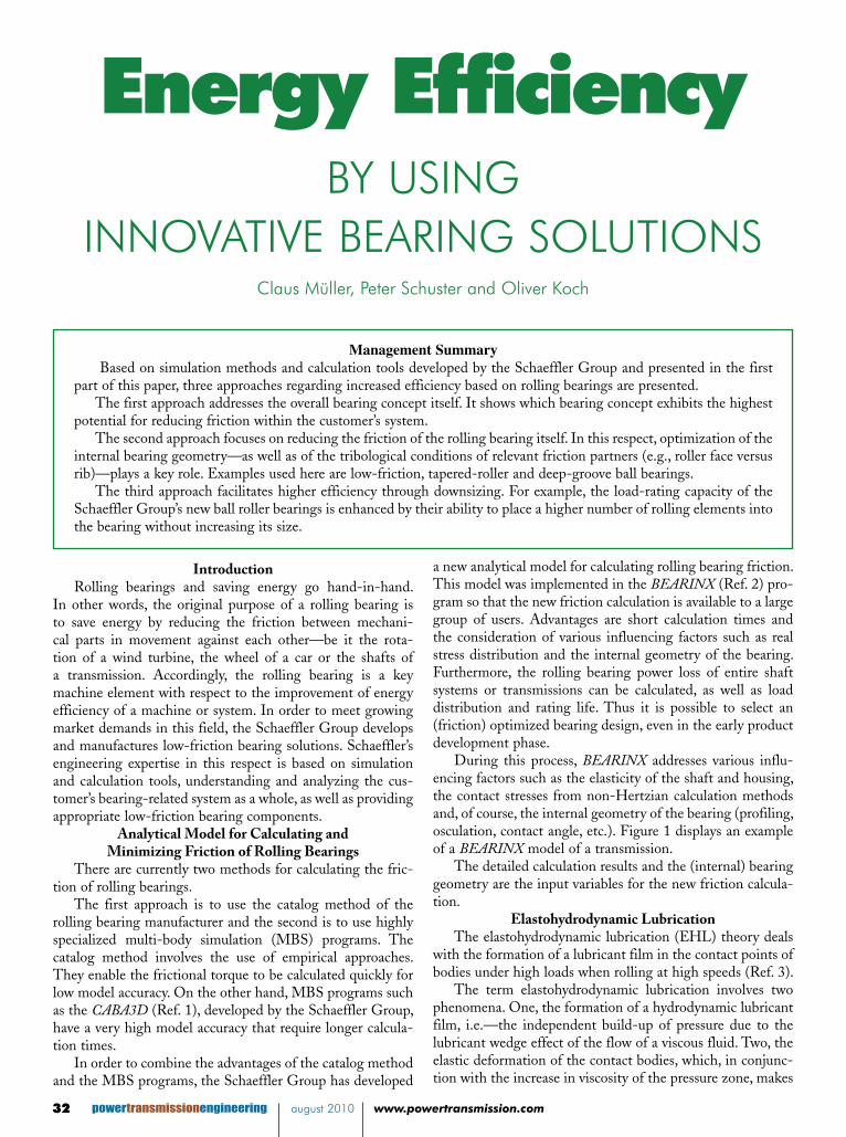
During this process, BEARINX addresses various influ-encing factors such as the elasticity of the shaft and housing, the contact stresses from non-Hertzian calculation methods and, of course, the internal geometry of the bearing (profiling, osculation, contact angle, etc.). Figure 1 displays an example of a BEARINX model of a transmission.
The detailed calculation results and the (internal) bearing geometry are the input variables for the new friction calcula-tion.
Elastohydrodynamic LubricationThe elastohydrodynamic lubrication (EHL) theory deals
with the formation of a lubricant film in the contact points of bodies under high loads when rolling at high speeds (Ref. 3).
The term elastohydrodynamic lubrication involves two phenomena. One, the formation of a hydrodynamic lubricant film, i.e.—the independent build-up of pressure due to the lubricant wedge effect of the flow of a viscous fluid. Two, the elastic deformation of the contact bodies, which, in conjunc-tion with the increase in viscosity of the pressure zone, makes
powertransmissionengineering august 2010 www.powertransmission.com www.powertransmission.com august 2010 powertransmissionengineering 33
continued
Fig. 1. Model of a passenger car manual transmission in BEARINX
Body 1,R1, E1
Body 2,R2, E2
Body 1,R1, E1
Body 2,R2, E2
Fig. 2. Elastohydrodynamic contact [5]
Fig. 3. Spinning friction illustrated with ball/plane
measuredmeasuredmeasuredmeasuredcalculatedcalculatedcalculatedcalculated
Sliding ratio [%]
Fric
tion
coef
ficie
nt [-
]
measuredmeasuredmeasuredmeasuredcalculatedcalculatedcalculatedcalculated
measuredmeasuredmeasuredmeasuredcalculatedcalculatedcalculatedcalculated
Sliding ratio [%]
Fric
tion
coef
ficie
nt [-
]
Fig. 4. Friction coefficient as a function of slip increase -
comparison of measurement and calculation
a significant contribution to the increase in hydrodynamic load-carrying capacity (Ref. 4).
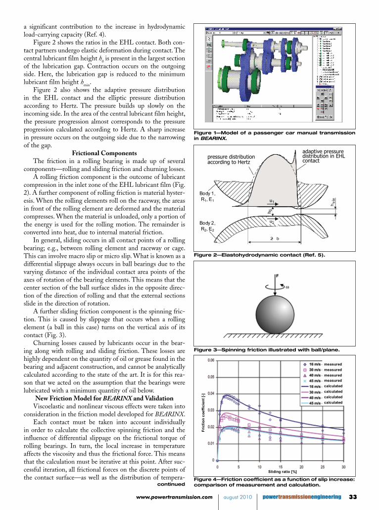
Figure 2 shows the ratios in the EHL contact. Both con-tact partners undergo elastic deformation during contact. The central lubricant film height h0 is present in the largest section of the lubrication gap. Contraction occurs on the outgoing side. Here, the lubrication gap is reduced to the minimum lubricant film height hmin.
Figure 2 also shows the adaptive pressure distribution in the EHL contact and the elliptic pressure distribution according to Hertz. The pressure builds up slowly on the incoming side. In the area of the central lubricant film height, the pressure progression almost corresponds to the pressure progression calculated according to Hertz. A sharp increase in pressure occurs on the outgoing side due to the narrowing of the gap.
Frictional ComponentsThe friction in a rolling bearing is made up of several
components—rolling and sliding friction and churning losses.A rolling friction component is the outcome of lubricant
compression in the inlet zone of the EHL lubricant film (Fig. 2). A further component of rolling friction is material hyster-esis. When the rolling elements roll on the raceway, the areas in front of the rolling element are deformed and the material compresses. When the material is unloaded, only a portion of the energy is used for the rolling motion. The remainder is converted into heat, due to internal material friction.
In general, sliding occurs in all contact points of a rolling bearing; e.g., between rolling element and raceway or cage. This can involve macro slip or micro slip. What is known as a differential slippage always occurs in ball bearings due to the varying distance of the individual contact area points of the axes of rotation of the bearing elements. This means that the center section of the ball surface slides in the opposite direc-tion of the direction of rolling and that the external sections slide in the direction of rotation.
A further sliding friction component is the spinning fric-tion. This is caused by slippage that occurs when a rolling element (a ball in this case) turns on the vertical axis of its contact (Fig. 3).
Churning losses caused by lubricants occur in the bear-ing along with rolling and sliding friction. These losses are highly dependent on the quantity of oil or grease found in the bearing and adjacent construction, and cannot be analytically calculated according to the state of the art. It is for this rea-son that we acted on the assumption that the bearings were lubricated with a minimum quantity of oil below.
New Friction Model for BEARINX and ValidationViscoelastic and nonlinear viscous effects were taken into
consideration in the friction model developed for BEARINX.Each contact must be taken into account individually
in order to calculate the collective spinning friction and the influence of differential slippage on the frictional torque of rolling bearings. In turn, the local increase in temperature affects the viscosity and thus the frictional force. This means that the calculation must be iterative at this point. After suc-cessful iteration, all frictional forces on the discrete points of the contact surface—as well as the distribution of tempera-
Figure 1—Model of a passenger car manual transmission in BEARINX.
Figure 2—Elastohydrodynamic contact (Ref. 5).
Figure 3—Spinning friction illustrated with ball/plane.
Figure 4—Friction coefficient as a function of slip increase: comparison of measurement and calculation.
pressure distribution according to Hertz
adaptive pressure distribution in EHL contact
powertransmissionengineering august 2010 www.powertransmission.com34
ture increases—are available in the calculation results. The redeveloped method for calculating friction with
BEARINX was comprehensively validated. During the first phase, friction measurements from 2-disc test rigs were used for the validation. Figure 4 shows the coefficient of friction as a function of the slippage for various accumulated speeds. The measurement values are shown as points and the calculated friction values as the continuous line. The decrease in the coefficient of friction is based on thermal effects. The corre-lation between measurement and calculation can be assessed as very good. This shows that BEARINX is capable in princi-ple of calculating the coefficient of friction of a single-defined contact correctly—both qualitatively and quantitatively.
In the final step of the validation, frictional torque values of rolling bearings were calculated with BEARINX and com-pared with measurements. It was shown that the correlation between the frictional torques, calculated using BEARINX, and the measurements is significantly greater than the cor-relation between the frictional torques calculated using the catalog methods of major rolling bearing manufacturers and the measurements (Ref. 6).
Bearing Concept for Customer Applications with Optimized Friction Characteristics
In order to identify the best low-friction solution for the customer, the new BEARINX friction calculation enables the assessment of bearing concepts and friction reduction potentials in the early phases of customer product design and development.
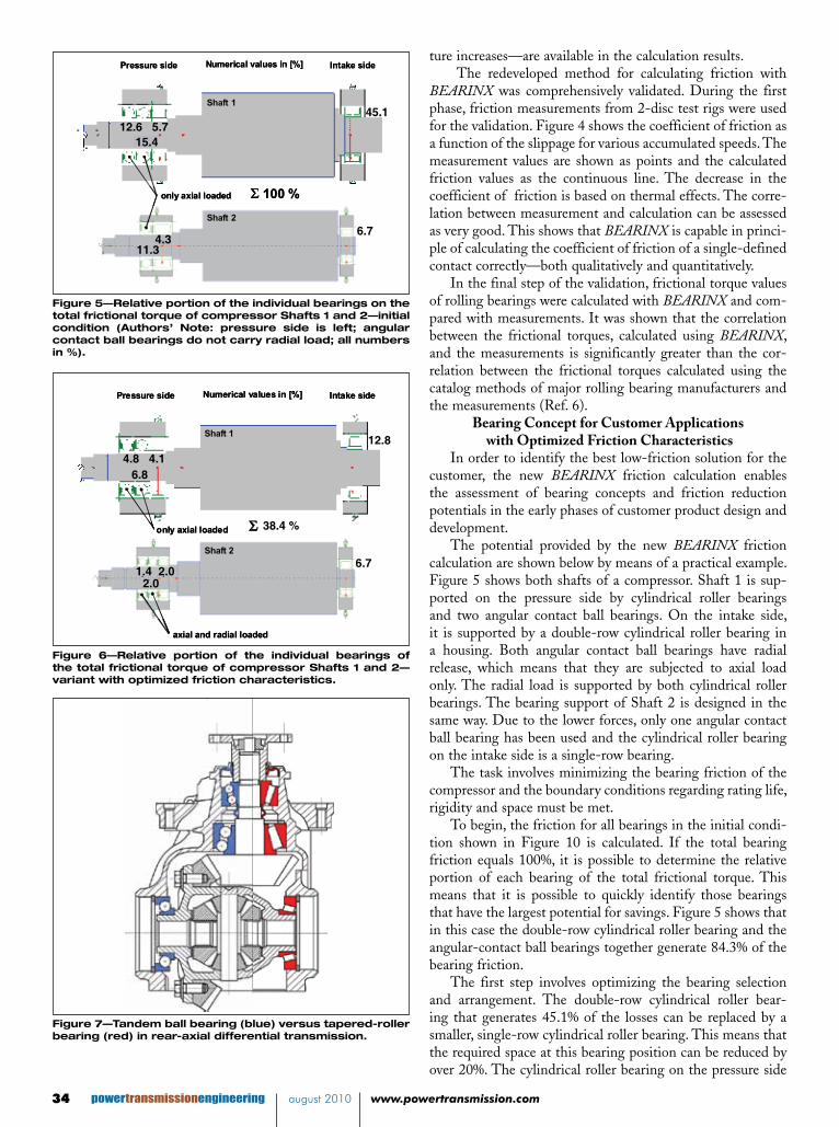
The potential provided by the new BEARINX friction calculation are shown below by means of a practical example. Figure 5 shows both shafts of a compressor. Shaft 1 is sup-ported on the pressure side by cylindrical roller bearings and two angular contact ball bearings. On the intake side, it is supported by a double-row cylindrical roller bearing in a housing. Both angular contact ball bearings have radial release, which means that they are subjected to axial load only. The radial load is supported by both cylindrical roller bearings. The bearing support of Shaft 2 is designed in the same way. Due to the lower forces, only one angular contact ball bearing has been used and the cylindrical roller bearing on the intake side is a single-row bearing.
The task involves minimizing the bearing friction of the compressor and the boundary conditions regarding rating life, rigidity and space must be met.
To begin, the friction for all bearings in the initial condi-tion shown in Figure 10 is calculated. If the total bearing friction equals 100%, it is possible to determine the relative portion of each bearing of the total frictional torque. This means that it is possible to quickly identify those bearings that have the largest potential for savings. Figure 5 shows that in this case the double-row cylindrical roller bearing and the angular-contact ball bearings together generate 84.3% of the bearing friction.
The first step involves optimizing the bearing selection and arrangement. The double-row cylindrical roller bear-ing that generates 45.1% of the losses can be replaced by a smaller, single-row cylindrical roller bearing. This means that the required space at this bearing position can be reduced by over 20%. The cylindrical roller bearing on the pressure side
Shaft 1
Shaft 2
edis ekatnIedis erusserP
12,515,4
Numerical values in [%]
5,745,1
11,34,3
5,7
only axial loaded Σ 100 %
Shaft 1
Shaft 2
edis ekatnIedis erusserP
12,515,4
Numerical values in [%]
5,745,1
11,34,3
5,7
only axial loaded Σ 100 %
Fig. 5. Relative portion of the individual bearings on the total frictional torque of compressor shafts 1 and 2 – ini-tial condition (note: pressure side is left; angular contact ball bearings do not carry radial load; all numbers in %)
Shaft 1
Shaft 2
edis ekatnIedis erusserP Numerical values in [%]
only axial loaded
axial and radial loaded
4,65,8
4,112,8
1,42,0
2,05,7
Σ 38,4 %
Shaft 1
Shaft 2
edis ekatnIedis erusserP Numerical values in [%]
only axial loaded
axial and radial loaded
4,65,8
4,112,8
1,42,0
2,05,7
Σ 38,4 %
Fig. 6. Relative portion of the individual bearings of the total frictional torque of compressor shafts 1 and 2 –
variant with optimized friction characteristics
Figure 5—Relative portion of the individual bearings on the total frictional torque of compressor Shafts 1 and 2—initial condition (Authors’ Note: pressure side is left; angular contact ball bearings do not carry radial load; all numbers in %).
Figure 6—Relative portion of the individual bearings of the total frictional torque of compressor Shafts 1 and 2—variant with optimized friction characteristics.
Fig. 7. Tandem ball bearing (blue) vs. tapered roller bearing (red) in rear axial differential transmission
Figure 7—Tandem ball bearing (blue) versus tapered-roller bearing (red) in rear-axial differential transmission.
45.1
6.7
12.6 5.7
4.311.3
15.4
12.8
6.7
4.8 4.16.8
1.4 2.02.0
38.4 %
powertransmissionengineering august 2010 www.powertransmission.com www.powertransmission.com august 2010 powertransmissionengineering 35
continued
of Shaft 1 can also be replaced by a smaller cylindrical roller bearing.
The cylindrical roller bearing on the intake side of Shaft 2 remains unchanged. A smaller, cylindrical roller bearing is now used on the pressure side. The angular-contact ball bearing is replaced by two smaller versions that do not have a radial release. This means that the radial load is split across all bearings on Shaft 2. The friction is reduced, since smaller bearings are used, and in the case of the angular contact ball bearings, the contact angle of the bearing is more favorable due to the combined loading. At the same time, 25% less space is required. Overall, the bearing friction can be reduced by 35.4% during the first stage of optimization.
During the second stage the osculation of the angular-contact ball bearings is optimized for this application. This enables a further reduction in friction of 11.3%.
The last stage involved investigating the influence of surface roughness on the frictional torque. In this case, it was possible to reduce the friction by a further 14.9% by optimiz-ing the design of the surface. Figure 6 shows the bearing sup-port with optimized friction characteristics and the friction at individual bearing positions. All percentage values refer to the total bearing friction of the original variant. By using BEARINX the friction can be reduced by 61.6%—compared with the original variant—while simultaneously reducing the space required for the bearing supports (Ref. 7).
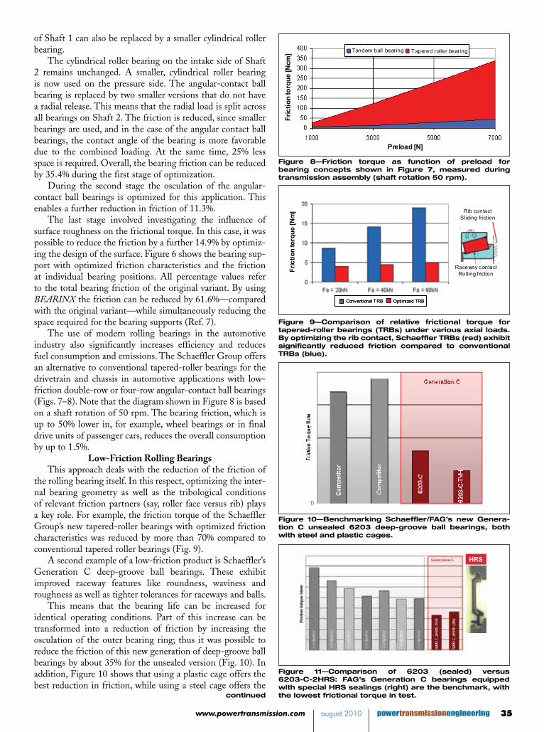
The use of modern rolling bearings in the automotive industry also significantly increases efficiency and reduces fuel consumption and emissions. The Schaeffler Group offers an alternative to conventional tapered-roller bearings for the drivetrain and chassis in automotive applications with low-friction double-row or four-row angular-contact ball bearings (Figs. 7–8). Note that the diagram shown in Figure 8 is based on a shaft rotation of 50 rpm. The bearing friction, which is up to 50% lower in, for example, wheel bearings or in final drive units of passenger cars, reduces the overall consumption by up to 1.5%.
Low-Friction Rolling BearingsThis approach deals with the reduction of the friction of
the rolling bearing itself. In this respect, optimizing the inter-nal bearing geometry as well as the tribological conditions of relevant friction partners (say, roller face versus rib) plays a key role. For example, the friction torque of the Schaeffler Group’s new tapered-roller bearings with optimized friction characteristics was reduced by more than 70% compared to conventional tapered roller bearings (Fig. 9).
A second example of a low-friction product is Schaeffler’s Generation C deep-groove ball bearings. These exhibit improved raceway features like roundness, waviness and roughness as well as tighter tolerances for raceways and balls.
This means that the bearing life can be increased for identical operating conditions. Part of this increase can be transformed into a reduction of friction by increasing the osculation of the outer bearing ring; thus it was possible to reduce the friction of this new generation of deep-groove ball bearings by about 35% for the unsealed version (Fig. 10). In addition, Figure 10 shows that using a plastic cage offers the best reduction in friction, while using a steel cage offers the
Fric
tion
torq
ue [N
cm]
Preload [N]
Tandem ball bearing T apered roller bearing
Fric
tion
torq
ue [N
cm]
Preload [N]
Tandem ball bearing T apered roller bearing
Fig. 8. Friction torque as function of preload for bearing concepts shown in Fig. 7, measured during transmission
assembly (shaft rotation 50 rpm)
Figure 8—Friction torque as function of preload for bearing concepts shown in Figure 7, measured during transmission assembly (shaft rotation 50 rpm).
Fric
tion
torq
ue [N
m]
Conventional TRB Optimized TRB
Raceway contactRolling friction
Rib contactSliding friction
Fric
tion
torq
ue [N
m]
Conventional TRB Optimized TRBConventional TRB Optimized TRB
Raceway contactRolling friction
Rib contactSliding friction
Fig. 9. Comparison of relative frictional torque for ta-pered roller bearings (TRBs) under various axial loads. By optimizing the rib contact, Schaeffler TRBs (red) ex-hibit significantly reduced friction compared to conven-
tional TRBs (blue)
Figure 9—Comparison of relative frictional torque for tapered-roller bearings (TRBs) under various axial loads. By optimizing the rib contact, Schaeffler TRBs (red) exhibit significantly reduced friction compared to conventional TRBs (blue).
Fig. 10. Benchmarking Schaeffler/FAG’s new Generation
C unsealed 6203 deep groove ball bearings, both with steel and plastic( ext. -TVH) cages
Figure 10—Benchmarking Schaeffler/FAG’s new Genera-tion C unsealed 6203 deep-groove ball bearings, both with steel and plastic cages.
HRSHRS
Fig. 11. Comparison of 6203 (sealed) vs. 6203-C-2HRS:
FAG’s Generation C bearings equipped with special HRS sealings (right) are benchmark with the
lowest frictional torque in test.
Figure 11—Comparison of 6203 (sealed) versus 6203-C-2HRS: FAG’s Generation C bearings equipped with special HRS sealings (right) are the benchmark, with the lowest frictional torque in test.
powertransmissionengineering august 2010 www.powertransmission.com36
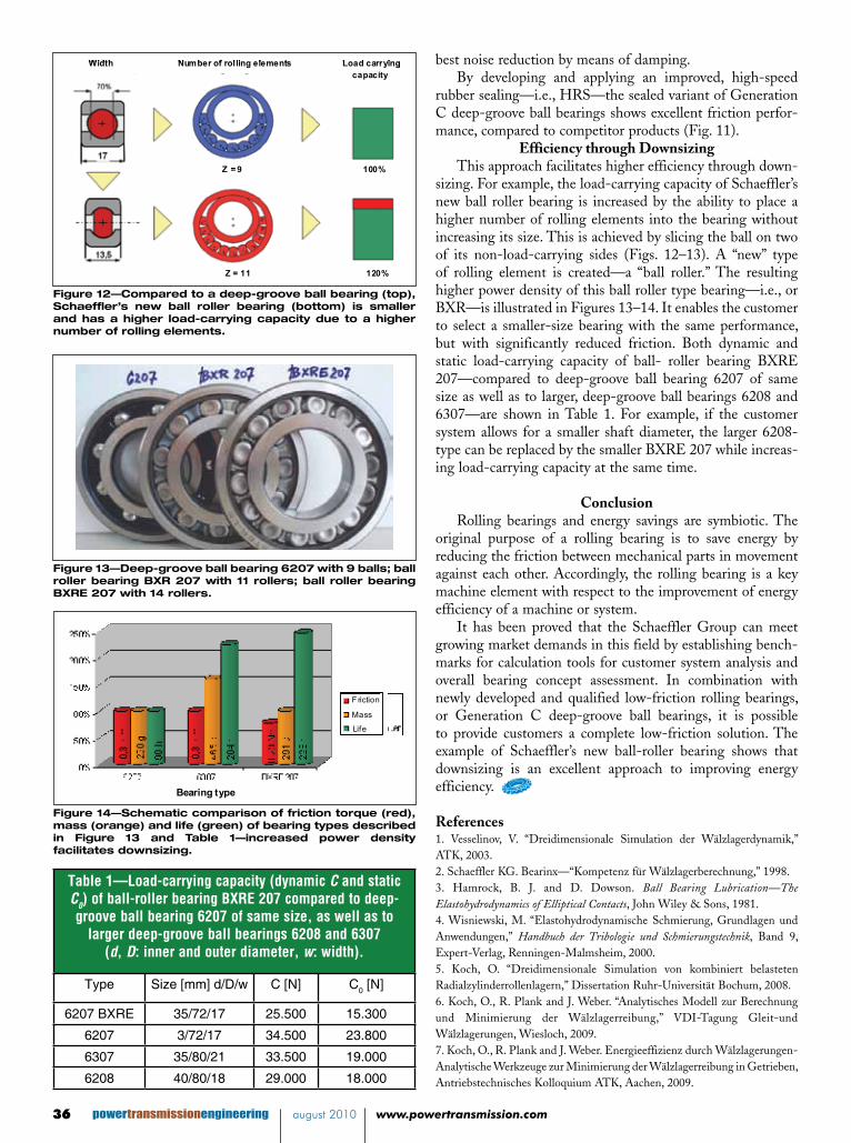
best noise reduction by means of damping.By developing and applying an improved, high-speed
rubber sealing—i.e., HRS—the sealed variant of Generation C deep-groove ball bearings shows excellent friction perfor-mance, compared to competitor products (Fig. 11).
Efficiency through DownsizingThis approach facilitates higher efficiency through down-
sizing. For example, the load-carrying capacity of Schaeffler’s new ball roller bearing is increased by the ability to place a higher number of rolling elements into the bearing without increasing its size. This is achieved by slicing the ball on two of its non-load-carrying sides (Figs. 12–13). A “new” type of rolling element is created—a “ball roller.” The resulting higher power density of this ball roller type bearing—i.e., or BXR—is illustrated in Figures 13–14. It enables the customer to select a smaller-size bearing with the same performance, but with significantly reduced friction. Both dynamic and static load-carrying capacity of ball- roller bearing BXRE 207—compared to deep-groove ball bearing 6207 of same size as well as to larger, deep-groove ball bearings 6208 and 6307—are shown in Table 1. For example, if the customer system allows for a smaller shaft diameter, the larger 6208-type can be replaced by the smaller BXRE 207 while increas-ing load-carrying capacity at the same time.
ConclusionRolling bearings and energy savings are symbiotic. The
original purpose of a rolling bearing is to save energy by reducing the friction between mechanical parts in movement against each other. Accordingly, the rolling bearing is a key machine element with respect to the improvement of energy efficiency of a machine or system.
It has been proved that the Schaeffler Group can meet growing market demands in this field by establishing bench-marks for calculation tools for customer system analysis and overall bearing concept assessment. In combination with newly developed and qualified low-friction rolling bearings, or Generation C deep-groove ball bearings, it is possible to provide customers a complete low-friction solution. The example of Schaeffler’s new ball-roller bearing shows that downsizing is an excellent approach to improving energy efficiency.
References1. Vesselinov, V. “Dreidimensionale Simulation der Wälzlagerdynamik,” ATK, 2003.2. Schaeffler KG. Bearinx—“Kompetenz für Wälzlagerberechnung,” 1998.3. Hamrock, B. J. and D. Dowson. Ball Bearing Lubrication—The Elastohydrodynamics of Elliptical Contacts, John Wiley & Sons, 1981.4. Wisniewski, M. “Elastohydrodynamische Schmierung, Grundlagen und Anwendungen,” Handbuch der Tribologie und Schmierungstechnik, Band 9, Expert-Verlag, Renningen-Malmsheim, 2000.5. Koch, O. “Dreidimensionale Simulation von kombiniert belasteten Radialzylinderrollenlagern,” Dissertation Ruhr-Universität Bochum, 2008.6. Koch, O., R. Plank and J. Weber. “Analytisches Modell zur Berechnung und Minimierung der Wälzlagerreibung,” VDI-Tagung Gleit-und Wälzlagerungen, Wiesloch, 2009.7. Koch, O., R. Plank and J. Weber. Energieeffizienz durch Wälzlagerungen-Analytische Werkzeuge zur Minimierung der Wälzlagerreibung in Getrieben, Antriebstechnisches Kolloquium ATK, Aachen, 2009.
Load carryingcapacity
Number of rolling elementsWidth
%0019 = Z
%02111 = Z
Load carryingcapacity
Number of rolling elementsWidth
%0019 = Z
%02111 = Z Fig. 12. Compared to a deep groove ball bearing (top), Schaeffler’s new ball roller bearing (bottom) is smaller and has a higher load carrying capacity due to a higher
number of rolling elements
Figure 12—Compared to a deep-groove ball bearing (top), Schaeffler’s new ball roller bearing (bottom) is smaller and has a higher load-carrying capacity due to a higher number of rolling elements.
Fig. 13. Deep groove ball bearing 6207 with 9 balls, ball roller bearing BXR 207 with 11 rollers, ball roller bear-
ing BXRE 207 with 14 rollers
Figure 13—Deep-groove ball bearing 6207 with 9 balls; ball roller bearing BXR 207 with 11 rollers; ball roller bearing BXRE 207 with 14 rollers.
Friction
Mass
Life
Bearing type
Friction
Mass
Life
Bearing type
Fig. 14. Schematic comparison of friction torque (red), mass (orange) and life (green) of bearing types described in figures 13 and Table 1: increased power density facili-
tates downsizing
Figure 14—Schematic comparison of friction torque (red), mass (orange) and life (green) of bearing types described in Figure 13 and Table 1—increased power density facilitates downsizing.
Table 1—Load-carrying capacity (dynamic C and static C0) of ball-roller bearing BXRE 207 compared to deep-groove ball bearing 6207 of same size, as well as to
larger deep-groove ball bearings 6208 and 6307 (d, D: inner and outer diameter, w: width).
Type Size [mm] d/D/w C [N] C0 [N]
6207 BXRE 35/72/17 25.500 15.300
6207 3/72/17 34.500 23.800
6307 35/80/21 33.500 19.000
6208 40/80/18 29.000 18.000
Dr. Oliver Koch has studied mechanical engineering at the Ruhr-University of Bochum, Germany. From 2003 to 2007 he completed his PhD studies under Prof. Predki at the chair of machine elements, transmissions and vehicles (Ruhr-University of Bochum), investi-gating three-dimensional simulation of combined, loaded cylindrical roller bearings. Since 2007 he has worked at Schaeffler Technologies GmbH & Co. KG in the bearing fundamentals department. He has developed the friction calculation for BEARINX and is responsible for the further development of the calculation methods of Schaeffler’s multi-body simulation tool CABA3D (Computer Aided Bearing Analyzer 3D).
Dr. Claus Müller studied materials science and engineering at the University of Erlangen-Nürnberg. In his PhD studies, completed carried at the department of materials science and engineering, Erlangen, he investigated high-temperature oxidation protection coat-ings. From 1998–2001 he worked for IAB GmbH in Munich/Ottobrunn as project engineer, developing and fabricating light-weight, composite components for use in the automotive and aerospace industries. In 2001 he joined MTU Aero Engines GmbH in Munich. As project manager, his responsibilities were technology development in the fields of materials, production and repair of turbine components. Since 2007 Dr. Müller has worked as project manager in the advance development department of Schaeffler Group Industrial in Her-zogenaurach. He manages the development cluster—energy-efficient bearings and systems.
Peter Schuster studied mechanical engineering at Technical University in Darmstadt. From 1997 to 2002 he worked at REHAU AG + Co in the household apppliances dept. as an application and product development engineer. From 2002 to 2005 he worked at Schaef-fler Group`s Central Engineering department as a project manager for fundamental development projects. Since 2005 Mr. Schuster has served as head of advance development at Schaeffler Group Industrial.