energy-efficient low power listening for wireless sensor ...lu/papers/ipsn13-aedp.pdf · low power...
TRANSCRIPT
Energy-Efficient Low Power Listening for Wireless SensorNetworks in Noisy Environments
Mo Sha, Gregory Hackmann, Chenyang LuDepartment of Computer Science and Engineering
Washington University in St. LouisOne Brookings Drive, Box 1045St. Louis, Missouri 63130, USA
{msha, ghackmann, lu}@wustl.edu
ABSTRACT
Low Power Listening (LPL) is a common MAC-layer tech-nique for reducing energy consumption in wireless sensornetworks, where nodes periodically wakeup to sample thewireless channel to detect activity. However, LPL is highlysusceptible to false wakeups caused by environmental noisebeing detected as activity on the channel, causing nodesto spuriously wakeup in order to receive nonexistent trans-missions. In empirical studies in residential environments,we observe that the false wakeup problem can significantlyincrease a node’s duty cycle, compromising the benefit ofLPL. We also find that the energy-level threshold used bythe Clear Channel Assessment (CCA) mechanism to detectchannel activity has a significant impact on the false wakeuprate. We then design AEDP, an adaptive energy detec-tion protocol for LPL, which dynamically adjusts a node’sCCA threshold to improve network reliability and duty cy-cle based on application-specified bounds. Empirical exper-iments in both controlled tests and real-world environmentsshowed AEDP can effectively mitigate the impact of noiseon radio duty cycles, while maintaining satisfactory link re-liability.
Categories and Subject Descriptors
C.2.2 [Computer-Communication Networks]: NetworkProtocols
General Terms
Design; Experimentation; Performance
Keywords
Wireless Sensor Networks; Low Power Listening; CCA Con-trol
Permission to make digital or hard copies of all or part of this work forpersonal or classroom use is granted without fee provided that copies arenot made or distributed for profit or commercial advantage and that copiesbear this notice and the full citation on the first page. To copy otherwise, torepublish, to post on servers or to redistribute to lists, requires prior specificpermission and/or a fee.IPSN’13, April 8–11, 2013, Philadelphia, Pennsylvania, USA.Copyright 2013 ACM 978-1-4503-1959-1/13/04 ...$15.00.
1. INTRODUCTION
Clear Channel Assessment (CCA) is a fundamental mech-anism in MAC protocols for wireless networks. A CCAcheck 1 samples the energy level in the wireless channel andconsiders the channel busy if the energy level is above athreshold, or idle otherwise. CCA has been commonly usedfor two important (and orthogonal) purposes. First, it hasbeen used by CSMA/CA protocols to avoid collisions onshared wireless channels, by sampling the channel for activ-ity just before transmission. Second, CCA has been used inLow Power Listening (LPL), a popular MAC-layer approachthat enables radio to operate at low duty cycles. UnderLPL, every node periodically wakes up to perform CCA. Itthen stays awake to receive packets if the CCA check detectsactivity in the wireless channel, or goes back to sleep imme-diately otherwise. Due to its simplicity and effectiveness,LPL has been a popular approach to energy-efficient MACprotocols in Wireless Sensor Networks (WSNs). A multi-tude of LPL-based MAC protocols has been developed inrecent years [8, 18, 19], and LPL has been implemented bymany radio drivers inside sensor operating systems such asTinyOS [1] and Contiki [2].
While the effect of CCA on collision avoidance has beenwell studied in the literature, its impact on LPL, particularlyin noisy environments such as residential and office environ-ments, has received relatively little attention. Applicationsdeployed in noisy wireless conditions are susceptible to fre-quent false wakeups: noise may be detected as legitimateactivity on the channel, causing the node to remain awakeeven when no transmissions occur. False wakeups may sig-nificantly increase the duty cycle and energy consumption ofthe nodes, as shown by our empirical studies in residentialenvironments (see Section 4). This limitation of LPL proto-cols is becoming increasingly significant as more and moreWSNs are being deployed in residential environments, whereco-existing wireless devices and electromagnetic equipmentscause prevalent and highly variable noise.
To address this important problem, we propose a novelapproach that dynamically adjusts the CCA threshold, i.e.,the energy level threshold used to decide if a channel is ac-tive. This approach is motivated by the key observationthat nodes may effectively reduce false wakeups by choosinga threshold above the background noise level, but below the
1CCA, carrier sense and energy detection are used as syn-onymous in this paper, as supported by [20].
level of real transmissions. Specifically, the main contribu-tions of this work are three-fold:
• An empirical study in residential environments thatdemonstrates the potential benefits of adaptive CCAcontrol based on both normal channel conditions andcontrolled 802.11n traffic;
• Adaptive Energy Detection Protocol (AEDP), an adap-tive protocol that dynamically adjusts a node’s CCAthreshold to improve network reliability and duty cyclebased on application-specified bounds;
• Discovery of significant shortcomings in the implemen-tation of CCA checks in TinyOS 2.1.1 2 caused by im-proper selections of key radio parameters, and a sys-tematic methodology to tune these parameters in orderto enable efficient CCA checks.
In contrast to previous studies on adjusting the CCAthreshold to better avoid collisions in both 802.11 [7] and802.15.4 [5, 6, 16, 27] networks, this paper investigates theCCA threshold’s role in waking up nodes, with the goal tomitigate the false wakeup problem associated with LPL; toour knowledge, it represents the first systematic study of theCCA threshold’s role in the effectiveness of LPL. The usesof CCA for collision avoidance in CSMA/CA and wakeupin LPL are orthogonal and complementary to each other,as CCA is being used at different times for different goals.Indeed, both forms of CCA adjustment could be deployedsimultaneously, by simply maintaining separate thresholdsfor collision avoidance and LPL.
The remainder of the paper is organized as follows. Sec-tion 2 compares our approach with related works. Section 3describes an overview of LPL. Section 4 presents an em-pirical study into the effect of noise on LPL behavior, andexplores the use of CCA thresholds to control the associatedfalse wakeup problem. Section 5 details the AEDP protocolfor dynamically adjusting a node’s CCA threshold in orderto minimize false wakeups. Section 6 describes the imple-mentation of AEDP on the TelosB mote platform and ana-lyzes the impact of radio parameters on the effectiveness ofCCA. Section 7 presents an empirical evaluation of AEDP inboth controlled tests and real-world environments. Finally,we conclude the paper in Section 8.
2. RELATED WORK
Traditionally, CCA functionality has been used in CS-MA/CA MAC protocols to avoid collisions on shared wire-less channels. A sender performs CCA before transmission.It proceeds with the transmission if the CCA check does notdetect channel activity; otherwise it backs off to avoid collid-ing with an on-going transmission. Numerous studies haveexplored the impact of the CCA thresholds used for collisionavoidance on both 802.11 networks and WSNs [5–7, 16, 27].Bertocco et al. [5] shows that the CCA threshold is critical,as false negative channel activity detections result in colli-sions and false positives cause increased latency. Kiryushinet al. [16] studies the real-world impact of CCA thresholdsin avoiding packet collisions. Chintalapudi et al. [9] showsthat a poor energy detection scheme can lead to significant
2The shortcomings still exist in TinyOS 2.1.2 officially re-leased on August 20, 2012.
overhead for listening to the channel and switching the radiobetween send and receive modes, which may take hundredsof microseconds. Boano et al. [6] shows that tuning the CCAthreshold at run time can improve the robustness of existingMAC protocols under interference. Yuan et al. [27] presentsthat dynamically adjusting CCA threshold can substantiallyreduce the amount of discarded packets due to channel ac-cess failures. Brodsky et al. [7] presents an opposite con-clusion based on theories of radio propagation and Shannoncapacity and shows that it is possible to choose a fixed CCAthreshold which performs well across a wide range of sce-narios since carrier sense performance is surprisingly closeto optimal for radios with adaptive bitrate. All these worksfocus on the impact of CCA on collision avoidance in trans-missions rather than its use for wakeup in LPL-based MACprotocols.
In contrast to previous studies on CCA for channel avoid-ance, this paper investigates the CCA threshold’s role inavoiding the false wakeup problem associated with LPL;to our knowledge, it represents the first systematic studyof the CCA threshold’s role in the effectiveness of LPL inachieving low duty cycles in WSNs, especially in noisy en-vironments where traditional LPL protocols are vulnerableto false wakeup problems. Our work is therefore orthogonaland complementary.
Recently, receiver-initiated MAC protocols have been pro-posed to avoid the false wakeup problem. Receiver-initiatedMAC protocols such as [12,23] require recipients to transmitprobe packets indicating that they are ready for packet re-ception. As our experiments presented in Section 7.5, AEDPis more energy efficient at low data rates than the state-of-the-art receiver-initiated MAC protocol A-MAC [12], asAEDP avoids the overhead of the probe packets. On theother hand, A-MAC is more energy efficient than AEDP forhigh data rate applications, where the cost of sending theseprobe packets are offset by reduced overhead for transmis-sions. Our work is therefore an alternative sender-initiatedapproach that is complementary to receiver-initiated MACsfor applications with different data rates.
ContikiMAC [11] addresses the false wakeup problem withtwo targeted optimizations. First, it performs two CCAchecks spaced slightly apart, allowing it to identify phe-nomenon too short to be an 802.15.4 transmission. Second,it performs a “fast sleep” optimization that reduces the costof false wakeups, by detecting patterns of activity and si-lence which cannot belong to ContikiMAC transmissions. Inour testing, we found that our approach’s CCA-threshold-adjustment can effectively avoid false wakeups without theseoptimizations. Since our approach requires only a singleCCA check, it induces lower energy cost in low duty-cyclecases where nodes rarely need to wakeup to receive pack-ets. Nevertheless, these approaches are orthogonal, and inparticularly challenging environments could be combined toreduce both the likelihood and the energy overhead of falsewakeups.
There has been increasing interest in studying the impactof interference on WSNs and enhancing the robustness ofMAC protocols in noisy environments. Srinivasan et al. [22]examines the packet delivery behavior of two 802.15.4-basedmote platforms, including the impact of interference from802.11 and Bluetooth. Liang et al. [17] measures the im-pact of interference from 802.11 networks on 802.15.4 links,proposing the use of redundant headers and forward error

correction to alleviate packet corruption. These studies fo-cus on improving the reliability of transmission and do notdeal with the false wakeup problem to improve energy effi-ciency.
3. OVERVIEW OF LPL
Low power listening (LPL) is a common MAC-layer tech-nique for reducing energy consumption in WSNs [19]. Un-der LPL, nodes periodically wakeup to perform CCA, i.e.,to briefly sample the wireless channel for activity. If energyis detected on the channel, the node remains awake in or-der to receive a packet (or until some timeout). Otherwise,the node quickly goes back to sleep. To minimize overheadwhen the network is idle, these periodic wakeups are notsynchronized across nodes: that is, the recipient knows therecipient’s wakeup interval but not its wakeup time. Accord-ingly, before transmitting a packet, the transmitter sends apreamble stream at least as long as the recipient’s wakeupinterval; this ensures that the recipient will sample the chan-nel during the preamble. After the preamble, the sender andrecipient exchange data packets.
Later LPL-based MAC layers such as X-MAC [8] modifythis approach by inserting destination address informationand periodic gaps in the preamble stream. When a nodewakes up, it may decode the destination address and see ifit is the packet’s intended recipient. If so, it uses the gapsin the preamble to send an acknowledgment to the sender,which will in turn immediately transmit the payload. Ifnot, the node may go back to sleep immediately. Theseenhancements significantly reduce the cost of waking up fora packet intended for another node, while also reducing theaverage cost of unicast packet transmissions by half. BoX-MAC-2 [18] further refines this approach by transmittingthe entire data packet in place of the destination address,eliminating the need to explicitly exchange the payload afterthe recipient has ACKed the preamble.
Quickly and accurately assessing whether the channelis active is a critical component of a LPL-based MAClayer. Modern radios, including all 802.15.4-compliant hard-ware [15], provide CCA functionality that assists with thisprocedure. A common method for radios to implement CCAis to provide a digital readout (often a dedicated pin) indi-cating whether the channel’s energy level currently exceedssome threshold. This particular implementation, known asenergy detection, is commonly found in low-power radiossuch as the Chipcon CC2420 and has been identified as acritical feature for WSN hardware design [13]. After wakingup the radio, the microcontroller may sample the CCA pinin a tight loop; the node remains awake for packet receptionif some minimum number of samples are positive.
4. EMPIRICAL STUDY
This section describes a series of empirical studies thatprovide the motivation and insights for the design of AEDP.We first measure the false wakeup problem in office and resi-dential environments, followed by a systematic study on theimpact of CCA’s energy detection threshold on wakeups inLPL.
4.1 Effects of Wireless Noise
Existing literature on LPL-based MAC layers emphasizesthe ability to run applications at an extremely low duty
cycle, sometimes as low as 1% [19], in exchange for mod-erately increasing the cost of packet transmissions. Thistradeoff makes LPL well-suited for applications with low-to-moderate data rates. However, noise from other wireless de-vices can have a dramatic (and often unanticipated) impacton nodes’ duty cycle, significantly reducing system lifetime.
Radios based on the 802.15.4 standard operate in the unli-censed 2.4 GHz band shared by many other devices. Energydetection simply looks for the presence of some signal onthe wireless channel; it does not distinguish between thesystem’s own traffic and noise from other devices. To illus-trate how a false-negative wakeup can considerably increasethe cost of a CCA check, we deployed a TelosB mote [10]running TinyOS 2.1.1 [1] in an office environment. TheTelosB mote was configured to use the BoX-MAC-2 LPL-based MAC layer, TinyOS’s de facto standard LPL im-plementation. BoX-MAC-2 was in turn configured with awakeup interval of 2 seconds: i.e., the motes sleep for 2seconds between sampling the channel for activity. In or-der to capture the effects of wireless noise, we configuredthe CC2420 radio to use channel 18, which overlaps witha campus-wide 802.11g network. All other MAC layer andradio parameters were left to their respective defaults.
0 20 40 60 80 100 120 140 160 180 200 22005
10152025303540
Time (ms)
Pow
er
(mW
)
Negative
False!positive
Figure 1: Oscilloscope traces comparing a TelosBnode’s energy consumption during a negative (idle)and false-positive (detected) energy detection check.
Figure 1 shows the energy consumption of this mote whenperforming a single energy detection check, as captured withan oscilloscope. When the channel is idle, the radio is pow-ered on for 19.0 ms; in contrast, when the channel is occu-pied, the false wakeup causes the radio to remain poweredon for 103.4 ms until it eventually times out. Similar resultswere observed in [12], which found that false wakeups in-creased the current consumption of a CCA check by 17.3×.
An equally important question is how often wireless noisewill cause these false wakeups to occur in real-world envi-ronments. To measure this phenomenon, we deployed fourpairs of TelosB motes on orthogonal channels (11, 16, 21,and 26, respectively) in five different apartments located indifferent neighborhoods in St. Louis. The motes were de-ployed for 24 hours in each apartment during the residents’normal activities. One mote in each pair was configured totransmit 1 packet every minute, and the BoX-MAC-2 MAClayer configured with a wakeup interval of 2 seconds. Weaugmented TinyOS’s CC2420 radio stack to track the re-sult of each CCA check and the radio “on time”, i.e., thecumulative total time the radio was active during the en-tire experimental run. The latter data was in turn used tocompute each mote’s duty cycle. For the purposes of thisexperiment, the mote’s onboard CC2420 was again config-ured with the hardware-default CCA behavior, setting itsCCA pin based on an energy threshold of −77 dBm.

Channel 11 Channel 16 Channel 21 Channel 260
10
20
30
40
50
Fals
e W
ake
up R
ate
(%
)
Apartment 1
Apartment 2
Apartment 3
Apartment 4
Apartment 5
Figure 2: The false wakeup rate of each recipientmote in each apartment.
Figure 2 plots the false wakeup rate (the proportion ofCCA checks resulting in wakeup but no packet reception)of each node in the experiment. From the receiver’s wakeupinterval and the sender’s data rate, we expect a nominalduty cycle of 0.17%. However, the false wakeups causedby environmental noise result in substantially higher dutycycles, with an average duty cycle of 1.4% across all fourtested channels in all five apartments. In the two worst cases— channel 16 in apartment 5 and channel 26 in apartment2 — false wakeup rates of 45% resulted in greatly inflatedduty cycles of 2.8%.
4.2 Effects of CCA Threshold
We propose to address the false wakeup problem by ad-justing the CCA threshold: that is, the specific energy levelused as a binary threshold to determine whether a nodeshould remain awake. In the context of LPL, setting theCCA threshold too low will cause nodes to wakeup to re-ceive non-existent packets. Setting the threshold too highmay cause nodes not to wakeup during transmissions, forcingthe sender to repeatedly retransmit. We note that adjustingthe CCA threshold for LPL has no effect on the receiver’sability to decode packets, so long as the threshold is lowenough to wakeup the receiver. Hence, link reliability willonly be affected if the threshold is high enough to causea false-negative energy detection (i.e., a node fails to stayawake to receive a legitimate packet).
As discussed earlier, the CCA threshold also plays a rolein the context of collision avoidance. However, adjusting theCCA threshold has a different effect in the context of col-lision avoidance, where it directly affects the sender ratherthan receivers. Setting the threshold too low encourages spu-rious backoffs, while setting the threshold too high may in-troduce packet losses from otherwise-avoidable collisions. Todistinguish the CCA threshold used by the receiver for LPLfrom the CCA threshold used by the sender in CSMA/CA,we henceforth refer to the former in this paper as the wakeupthreshold. This paper focuses on reducing false wakeups bymanipulating the wakeup threshold used for LPL. We do notchange the CCA threshold used for transmission, an impor-tant but orthogonal problem that has been well-studied inliterature.
We perform a set of controlled tests in an office environ-ment to investigate the potential energy savings from adjust-ing the wakeup threshold, we deployed five groups of fourTelosB motes on channel 16 at varying distances (3–15 ft)from a pair of 802.11n devices (access point+MAC pro lap-top) operating on 2.4 GHz band that overlaps with 802.15.4.Each experimental run was carried out for one hour; as be-
!77 !67 !57 !470
10
20
30
40
Wakeup Threshold (dBm)
Fals
e W
ake
up R
ate
(%
)
3ft
6ft
9ft
12ft
15ft
(a) False wakeup rate under office occupants’normal activities.
!77 !67 !57 !470
10
20
30
40
50
60
70
80
90
100
Wakeup Threshold (dBm)
Fals
e W
ake
up R
ate
(%
)
3ft
6ft
9ft
12ft
15ft
(b) False wakeup rate under controlled (5 MbpsUDP) 802.11n traffic.
Figure 3: The effects of tuning the CC2420’s wakeupthreshold on the motes’ false wakeup rate, subjectto office occupants’ normal activities and controlled802.11n traffic. The motes were located 3–15 ft awayfrom the 802.11n router, and were configured to usea threshold ranging from −77 to −47 dBm.
fore, BoX-MAC-2 was configured with a wakeup interval of2 seconds. In contrast to the previous experiments, whichused the radio-default CCA threshold of −77 dBm, eachmote in a group was configured to use one of four differentthresholds (−77, −67, −57, and −47 dBm). Signal gener-ated by motes may become part of the background noisewhen its strength is lower than recipients’ CCA threshold.We intentionally stop motes from generating real transmis-sions in this set of tests, thus we can treat the total wakeuprate as the false wakeup rate.
Figure 3(a) plots the recipients’ false wakeup rate underthe office occupants’ normal activities in real-world environ-ment. Figure 3(b) plots the false wakeup rate when usingLanTraffic V2 [3] to generate a controlled stream of 5 MbpsUDP traffic through the pair of 802.11n devices. Two im-portant conclusions may be drawn from these figures. First,tuning the wakeup threshold provides a powerful opportu-nity for conserving energy. We observe that the false wakeuprate drops dramatically when increasing the threshold fromthe radio default of −77 dBm. Under real-world activity asshown in Figure 3(a), the default threshold incurs a falsewakeup rate of 14–33%. In comparison, this rate may bereduced to 3–12% by moderately increasing the thresholdby 10 dBm, or to 0% by increasing the threshold by 30dBm. The effects of tuning the threshold are even morepronounced under the higher-bandwidth controlled exper-iments, as shown in Figure 3(b). At a threshold of −77dBm, the nodes experience a false wakeup rate no lowerthan 97.8%, regardless of distance from the pair of 802.11ndevices. This rate drops to 0–4% for two of the distances
at a threshold of −57 dBm, and to 0% for all distances at athreshold of −47 dBm. Second, the “best”wakeup thresholdis highly dependent on external factors such as the 802.15.4nodes’ vicinity to other devices, and the other devices’ us-age patterns and signal strength. Comparing Figures 3(a)and 3(b), we see that increasing the threshold from−77 dBmto −67 dBm significantly reduces the false wakeup rate un-der normal activities. However, under a sustained 5 MbpsUDP stream, a comparable threshold increase has virtuallyno impact on the false wakeup rate.
We also used motes to perform a series of measurementson signal strength of external interference generated by sev-eral real-world 802.11 applications as well as the LanTrafficV2 with various speeds. We observed that noise varies fromapplication to application and over time for a given applica-tion depending on the distance from interference source.
Hence, picking an appropriate wakeup threshold is notsimply a matter of choosing a more aggressive default set-ting. The minimum threshold needed to avoid noise variesfrom setting to setting, and even over time depending onthe occupants’ activities. Moreover, selecting too high of athreshold will intuitively cause the receiver to stop wakingup for legitimate transmissions, decreasing network reliabil-ity.
5. PROTOCOL DESIGN
In this section, we present the design of our Adaptive En-ergy Detection Protocol (AEDP). At a high level, AEDPtries to meet application-specified constraints on networkreliability and wakeup rate. The desired network reliabilityis specified by the desired ETX, ETXthreshold, where ETX isthe expected number of transmissions needed to successfullysend a packet to its destination. The desired wakeup rate,WRthreshold can be determined based on the applicationdata rate (and hence the corresponding true wakeup rate)plus a small margin for false wakeups allowed by the appli-cation. When it is not possible to meet both constraints,network reliability takes precedence, as it is typically morecritical than lifetime constraints. We set a default value ofETXthreshold to be 5 and a default value of WRthreshold tobe 5 times of data rate according to the typical low datarate home automation systems.
AEDP maintains three variables at run time: ETX, WR,and WRL. ETX is the average ETX value over a slidingwindow (default window size is 15 minutes). WR is thewakeup rate within the same sliding window. WRL is thecumulative wakeup rate over the whole application lifetime.Note that WRL reflects the long-term wakeup rate that af-fects the battery life of the node.
At runtime, AEDP periodically updates these three vari-ables ETX, WR, and WRL and compares their valuesagainst ETXthreshold and WRthreshold. It then computesa new wakeup threshold T based on four different cases, de-scribed below.
• Case 1: ETX exceeds ETXthreshold. AEDP at-tempts to quickly recover by significantly reducing thewakeup threshold. This policy reflects the fact thatnetwork reliability constraints are typically more crit-ical than lifetime constraints.
• Case 2: ETX meets ETXthreshold but WR exceedsWRthreshold. This case indicates that the current
wakeup threshold is too low to achieve the desiredwakeup rate. AEDP increases the wakeup thresholdby a small amount ∆T to try to meet the applica-tion’s bound on wakeup rate. The default value of thetuning step ∆T is set to be 2 dBm.
• Case 3: ETX, WR, and WRL all meet their re-spective constraints. This case indicates that the cur-rent wakeup threshold is meeting the application’s con-straints, both in this period and over the application’slifetime. AEDP aims to find the minimum thresholdthat does so, as lower wakeup thresholds are poten-tially more robust to changes in topology and signalstrength. Hence, AEDP decreases the wakeup thresh-old by ∆T .
• Case 4: ETX and WR meet their constraints butWRL does not. Here, AEDP takes no action. SinceWR is below WRthreshold, the wakeup threshold ishigh enough to meet the application’s wakeup rate con-straint in the short term. However, WRL has still notmet the application’s constraint over the long term, soAEDP will not yet start to reduce the wakeup thresh-old.
In all cases, AEDP constrains the wakeup threshold T toa range [Tmin, Tmax]. Reducing T too much will cause thenode to always be awake, while increasing T too much willcause packet loss (increased ETX). AEDP sets Tmin to bethe noise floor to avoid sustained wakeups, and sets Tmax tobe the minimum Received Signal Strength (RSS) of incom-ing links, since our experimental results have shown thatlink reliability degrades heavily when T exceeds the RSSof incoming link [21]. To accommodate topology changes,AEDP periodically resets the wakeup threshold to Tmin forseveral periods (a default value of 5 wakeup intervals) en-abling node to establish new incoming links with RSS lowerthan T .
AEDP has several key design features based on the obser-vations in our empirical study. First, AEDP adaptively ad-justs energy detection threshold based on changes in networkreliability (specifically, ETX) observed at runtime. Sec-ond, AEDP performs its computations based solely on lo-cal state (WR, WRL, and ETX), requiring no additionaltransmissions between sender and receiver. Third, AEDPis a lightweight protocol that only piggybacks a single byte(used to measure ETX) in each existing packet transmission,and introduces no other traffic of its own.
6. IMPLEMENTATION
In this section, we discuss our implementation of AEDPon TinyOS 2.1.1. We first describe the software architectureused by AEDP. We then discuss several key radio parametersthat affected the energy efficiency of LPL, and present amethodology for picking these parameters appropriately.
6.1 AEDP Architecture
We implement the AEDP algorithm as a layer situated be-tween the application and MAC layers. This layer consistsof three important components. The WakeupRateMonitorcomponent tracks the wakeup rate WR and computes thecumulative wakeup rate WRL. The LinkEstimator compo-nent measures the ETX of incoming packets using sequencenumbers in each packet, and computes the average ETX

!80 !70 !60 !50 !40 !30 !20 !10 01
1.05
1.1
1.15
1.2
1.25
1.3
Wakeup Threshold (dBm)
ET
X
Channel 11
Channel 16
Channel 26
Figure 4: The relationship between wakeup thresh-old and ETX in the default TinyOS CC2420 stack.
value (ETX) over a sliding window. The LinkEstimatoralso measures the RSS of incoming packets, using the mini-mum average RSS value of all incoming links as the boundTmax. The CCAControlEngine component computes andsets the wakeup threshold based on the values ETX, WRand WRL.
AEDP requires several modifications to the radio stack tosupport its operations, as listed below. For the purposes ofthis implementation, we have performed these modificationson TinyOS 2.1.1’s default CC2420 + BoX-MAC-2 stack.
First, we add a PacketInfo interface between the MAClayer and LinkEstimator to expose the ETX and RSS valuesof each incoming packet. The LinkEstimator buffers thevalues in sliding windows, calculating the average ETX andRSS values for the variables ETX and Tmax respectively.
Second, we augment the radio core to count wakeup events.This counter is exposed to the WakeupRateMonitor throughthe WakeupCounter interface and used to compute the val-ues of WR and WRL.
Finally, we add a CCAcontrol interface to the radio core toexpose the radio’s hardware CCA threshold setting. On theCC2420, this is implemented by writing the new threshold tothe radio’s CCA_THR register, plus a 45 dBm offset specifiedby the datasheet [24]. The CCA Control Engine uses thisinterface to set the newly-computed wakeup threshold T .
6.2 System Parameters
When testing our first implementation of AEDP on theTelosB mote, we were initially surprised to discover thatincreasing the wakeup threshold had little impact on net-work reliability. Figure 4 plots the relationship between thewakeup threshold and ETX that we observed in our ini-tial testing, using three different channels and a wide rangeof threshold values. We initially expected that an exces-sively high threshold would cause significant packet loss, anda high enough threshold would prohibit the node from re-ceiving packets at all (due to never waking up from sleep).However, in practice, we observed that an overly aggressivethreshold only increased the number of retransmissions bya maximum of 20%. Indeed, the node still received packetsafter setting the threshold to the radio maximum of 82 dBm,or even after modifying the CC2420 stack to always put theradio back to sleep regardless of the energy detection result.
From these results, we hypothesized that the radio wasfully receiving and decoding entire packets during the CCAcheck itself. TinyOS’s implementation of BoX-MAC-2 on
the CC2420 detects energy by sampling the CCA pin up to400 times in a tight loop. Modern packet-based radios likethe CC2420 are designed to fully decode packets withoutthe microcontroller’s intervention, and could decode packetswhile the microcontroller is occupied by polling the CCApin.
We confirmed this hypothesis using a logic analyzer totrace the sequence of events inside the radio hardware andradio stack. Figure 5 presents a sample trace that we cap-tured with the CC2420 configured to use the maximum thresh-old3. At 0 ms, the radio stack begins sampling the wirelesschannel by powering on the CC2420. The CC2420 is fullypowered on at T1 = 2.947 ms, and the radio stack startsenergy detection. At T2 = 5.916 ms, the CC2420 signalsthe beginning of a packet reception; at T3 = 7.261 ms, theCC2420 signals that the packet is fully decoded. The radiostack will not finish energy detection until T4 = 11.791 ms.Indeed, the duration of this check (8.844 ms) is much longerthan the on-air time of an 802.15.4 packet (0.59 − 4.24 msin lab experiments, depending on payload size).
The apparent cause for this lengthy check is a long ACKdelay built into TinyOS’s CC2420 driver. After transmittinga packet, the driver waits up to 8 ms for an ACK packet. Inour own measurements, this resulted in BoX-MAC-2 leavingthe channel idle for 8.3 ms between retransmissions.
In principle, an ACK delay of this length is unneces-sary. From the 802.15.4 specification, we can derive a tightbound of 544 µs on the ACK delay. (Specifically, the recip-ient must transmit an ACK exactly 192 µs after decodingthe incoming packet’s last bit, and transmitting the ACKpacket takes 352 µs at 802.15.4’s 250 kbps data rate [12,15].) However, TinyOS disables the CC2420’s hardwareauto-acknowledgement feature due to concerns over its relia-bility [4]. Consequently, packets must pass partway throughthe recipient’s radio stack before they are acknowledged,adding significant delay.
Nevertheless, we believe that the default ACK delay isoverly conservative. In a microbenchmark experiment, wetransmitted packets between a pair of TelosB motes withhardware auto-acknowledgement disabled. The transmitterrequested an ACK for each transmission, and recorded thedelay between finishing a transmission and receiving the cor-responding ACK. Out of 2000 transmissions, the transmitterobserved a mean delay of 2.2 ms and a maximum delay of2.4 ms.
This result indicates that an 8 ms ACK delay, and theassociated 8.8 ms energy detection length, is excessive. Thelength of this check contradicts the need for a short, inexpen-sive energy detection, and arguably even renders the entirecheck ineffective. From the 20% ETX penalty we observed inour testing, it would have been nearly as effective to simplyleave the radio on for 8.8 ms, and ignore the energy detec-tion result. Doing so would have had only a small impact onnetwork reliability, in exchange for never incurring a falsewakeup.
Instead, for the purposes of implementing and evaluatingAEDP, we opt to retain the check but reduce the CC2420
3For illustrative purposes, we modified BoX-MAC-2 to markthe duration of the energy detection loop using a GIO pin,and to disable a code branch that short-circuits the loopwhen the radio starts receiving a packet. We have verifiedthat the CC2420 will still fully decode packets during energydetection, even without these modifications.

Figure 5: A logic analyzer trace demonstrating the CC2420 fully decoding a packet during the energydetection check. The microcontroller uses the VREG EN pin to control the CC2420’s power state. TheCC2420 uses the SFD and FIFOP pins to signal the beginning (T2) and end (T3) of packet reception,respectively. The GIO pin indicates the duration of the check (T4–T1).
Driver ACK delayCC2420(cc2420 driver) 8 msCC2420(cc2420x driver,most platforms) 1 msCC2420(cc2420x driver,micaz platforms) 0.8 msCC2520 (most platforms) 1 msCC2520(sam3s_ek platform) 0.8 msRF230 1 ms
IEEE 802.15.4 specification 0.544 msTelosB (lab measurements) 2.4 ms
Table 1: The ACK delays used by various 802.15.4radio drivers in TinyOS, the ACK delay derivedfrom [15], and the actual ACK delay measured on aTelosB.
driver’s ACK delay to 2.8 ms (2.3 ms + 0.5 ms guard space).We accordingly modify BoX-MAC-2 to poll the CCA pin upto 115 times, reducing the energy detection duration from8.8 ms to 2.9 ms. In general, the duration of CCA pollingmust be longer than the ACK delay to avoid false negativesin energy detection which can heavily worsen the perfor-mance.
As we show in Section 7, this modification alone has theeffect of significantly reducing the motes’ duty cycle, simplyby reducing the cost of energy detection to a fraction of itsdefault length.
Although this modification is specific to the particular ra-dio stack used, it emphasizes the need for a general method-ology — such as the analysis performed above — to tunethese key radio and MAC layer parameters. Indeed, asshown in Table 1, TinyOS employs three different ACK de-lays on the sender side, depending on the combination of ra-dio driver, radio stack, and underlying mote platform. Noneof these three different delays is consistent with the theoret-ical ACK turnaround time from the 802.15.4 standard, orwith the actual turnaround time measured on the TelosB.Besides energy efficiency, this inconsistency raises concernsabout basic interoperability.
7. EVALUATION
To validate the efficiency of our approach in reducing falsewakeup rates, we performed a series of controlled experi-ments and real-world experiments. (1) We first evaluate thecapability of AEDP to effectively converge to the desiredwakeup threshold. (2) We then performed an experimentwhere additional transmitters were added to the networkat runtime to test AEDP’s resilience to network changes.
(3) We evaluate AEDP’s impact on duty cycles at the linklevel, and compare AEDP’s performance against LPL con-figurations in a testbed we deployed in a 3-floor apartmentbuilding. (4) We compare AEDP against A-MAC, a state-of-the-art receiver-initiated MAC protocol under differentdata rates. (5) Finally, we evaluate the impacts of AEDPon multi-hop data collection by running AEDP with CTPin a 55-node testbed in an academic building.
In all experiments, we deploy our benchmark applicationson top of TelosB motes running the TinyOS 2.1.1 operatingsystem. BoX-MAC-2 is configured with a wakeup intervalof 2 seconds: i.e., the motes sleep for 2 seconds betweensampling the channel for activity. We use a data rate of1 packet/5 minutes 4 for all evaluations except the one inSection 7.5, where we evaluate the performance of AEDPunder different data rates.
We emphasize that our experiments changed only the CCAthreshold used for wakeup and did not change the thresholdused for collision avoidance; hence, improvements in dutycycle are attributed to a reduction in false wakeups ratherthan retransmissions.
7.1 Self-tuning Wakeup Threshold
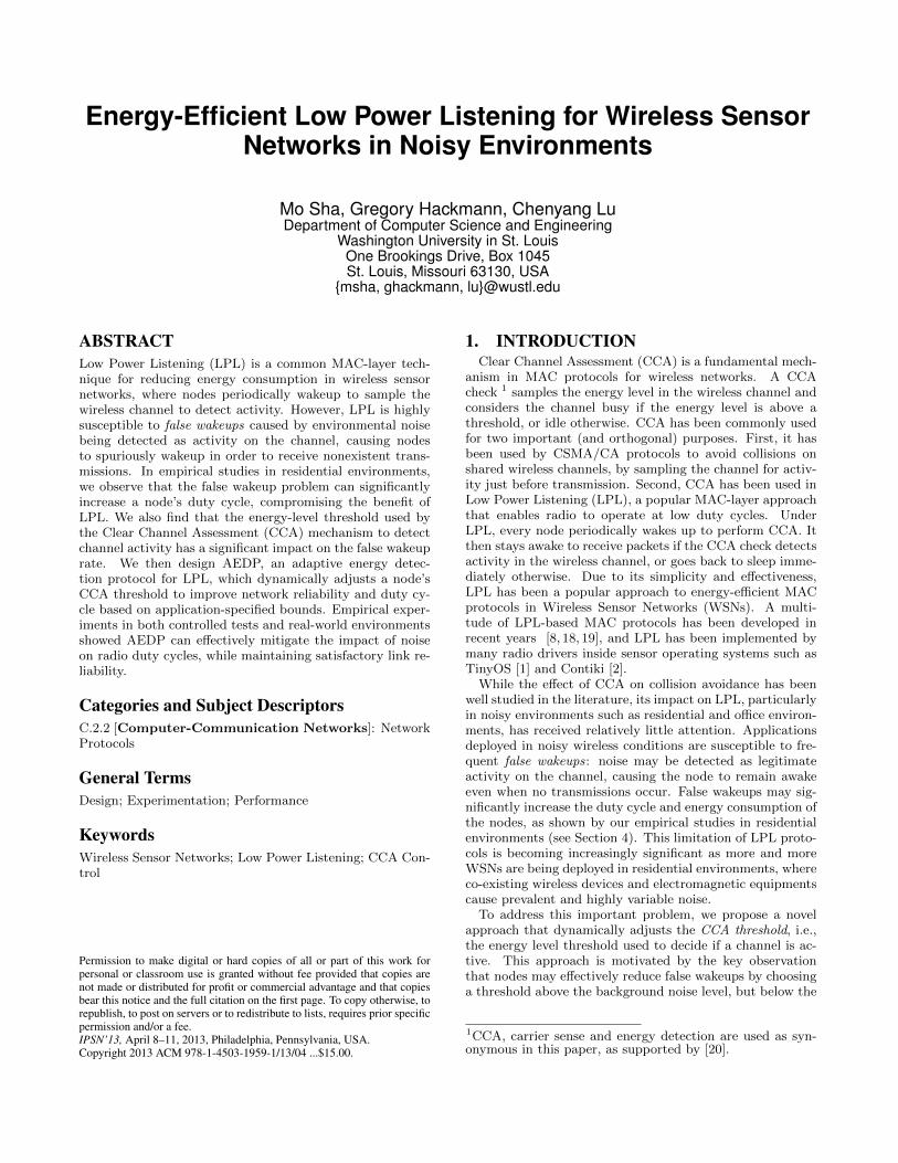
We first test the capability of AEDP to automatically ad-just its wakeup threshold. For this experiment, we deployeda pair of motes with AEDP on channel 16. We also de-ployed an 802.11n access point and a laptop producing 1Mbps of UDP traffic on 802.11 channel 6, which overlapswith 802.15.4 channel 16. We performed two experimentalruns: to vary the impact of the interfering 802.11 network onthe mote pair, the distance between the mote pair and the802.11n devices was 10 ft during the first run, and increasedto 30 ft for the second run.
Figure 6 illustrates AEDP reactively changing the wakeupthreshold based on runtime conditions. During the firstexperimental run, the receiver mote quickly increases thewakeup threshold to −56 dBm to avoid false wakeups intro-duced by the nearby 802.11 interferer. At this point, themote is still unable to meet the application-specified dutycycle, and hence the threshold remains at about −55 dBmfor the remainder of the experiment. In the second experi-mental run, the receiver mote likewise quickly increases thewakeup threshold to −54 dBm. At this point, because themote is located further away from the interferer, it is able to
4The data rate is chosen according to the typical samplingrate of home automation systems (for example, 1 tempera-ture reading every 5 minutes is sufficient for an HVAC sys-tem to control ambient temperature).
0 5 10 15 20 25 30 35 40 45 50 55 60!80
!75
!70
!65
!60
!55
!50
Time (min)
Wake
up T
hre
shold
(dB
m)
1st run (10ft from interferer)2nd run (30ft from interferer)
Figure 6: AEDP adapting the wakeup thresholdover time.
0 5 10 15 20 25 30 35 40 45 50 55 60!80
!75
!70
!65
!60
!55
!50
Time (min)
Wake
up T
hre
shold
(dB
m)
Figure 7: AEDP adapting the wakeup thresholdover time when new nodes join the network. A sec-ond transmitter joined into the network at 21 min-utes (vertical black line) and a third at 41 minutes(vertical red line).
meet the application-specified duty cycle; hence, it gradu-ally decreases the wakeup threshold in increments of 2 dBm.AEDP eventually settles on a threshold between −60 and−62 dBm that closely matches the requested duty cycle,where it remains for the remainder of the experiment.
7.2 Adaptation to Network Changes
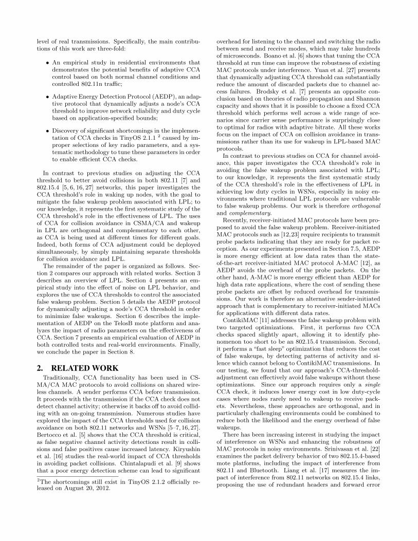
To test AEDP’s resilience to network changes, we per-formed an experiment where additional transmitters wereadded to the network at runtime. We initially deployed asingle transmitter mote and a single receiver mote. A secondtransmitter was added to the network 21 minutes into theexperiment, and a third was added at 41 minutes. All threetransmitters were configured to send packets to the singlereceiver node, where we instrumented AEDP to record itswakeup threshold over time.
Figure 7 illustrates how AEDP adapts the receiver’swakeup threshold over the course of the experiment. In orderto reduce the false wakeup rate, AEDP quickly increases thewakeup threshold to −52 dBm; this closely matches the −50dBm RSS of the first transmitter. After AEDP reaches itsobjective false wakeup rate, it begins steadily decreasing thethreshold until the second transmitter joins at 21 minutes.The second transmitter’s signal strength is slightly higher(−46 dBm) than the existing transmitter. Hence, AEDP re-sponds to the new node by increasing the threshold to −52dBm, slightly lower than the minimum of both transmit-ters, and again gradually decreases the threshold over time.At 41 minutes, the third transmitter joins with a signifi-cantly lower signal strength at the receiver (−60 dBm) thanthe previous two transmitters. Benefiting from the periodi-cal wakeup threshold reset process mentioned in Section 5,
0 10 20 30 40 50
0.2
0.3
0.4
0.5
0.7
0.608
0.259
Time (min)
Duty
Cyc
le (
%)
AEDPReduced ACK delayDefault
(a) In a clean environment.
0 10 20 30 40 50
0.2
0.3
0.4
0.5
0.7
0.8
0.9
1
0.259
0.608
Time (min)
Duty
Cyc
le (
%)
AEDPReduced ACK delayDefault
(b) In a residence with residents’ normal activi-ties.
0 10 20 30 40 500
0.5
1
1.5
2
2.5
3
0.259
0.608
Time (min)
Duty
Cyc
le (
%)
AEDPReduced ACK delayDefault
(c) In a lab stress test with generated 802.11ninterference.
Figure 8: Duty cycle under minimum interference,normal residential activities, and sustained interfer-ence. Horizontal lines indicate the theoretical opti-mal duty cycles of 0.259% (AEDP and reduced-ACKconfigurations) and 0.608% (default radio configura-tion).
AEDP adapts by rapidly dropping the wakeup threshold to−62 dBm, again slightly below the minimum signal strengthof all the transmitters. These results demonstrate AEDPdynamically adjusting the wakeup threshold to successfullyaccommodate network topology changes.
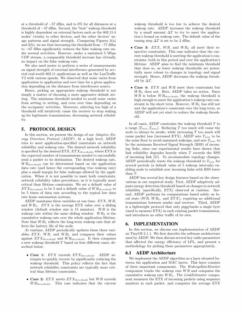
7.3 Impact on Duty Cycles
To explore AEDP’s impact on duty cycles, we deployed apair of motes with a modified radio stack to record the radioon time — i.e., the cumulative time the radio was active —on each mote. The precise duty cycle is hence derived fromthe radio on time and the experiment’s length.
We first deployed the pair on channel 26 in an office en-vironment, which we confirmed to be clean with a Wi-Spyspectrum analyzer [25]. We performed experimental runs,for 60 minutes each run, once with the default BoX-MAC-2 configuration and once with AEDP. To isolate the effectsof the reduced ACK delay (discussed in Section 6.2) fromAEDP’s wakeup threshold tuning, we performed a third ex-

perimental run which reduced the ACK delay but was oth-erwise identical to the default BoX-MAC-2 stack.
Figure 8(a) presents the duty cycle under all three ex-perimental runs, broken down into 5 minute windows. Ineach 5-minute window, the default BoX-MAC-2 configura-tion activates the radio with an average duty cycle of 0.64%.AEDP consistently reduces this duty cycle over the entireexperimental run, by an average of 57.48%. In this clean en-vironment, the false wakeup rate is very low; hence, AEDPachieves a duty cycle within 99.7% of the reduced-ACK con-figuration.
For comparison, we also plot the theoretical optimal dutycycle for both ACK delay configurations. Specifically, at adata rate of 1 packet/5 min and a wakeup interval of 2 s,the optimal duty cycle is 149 ∗Tidle +(Tp +Ti)/2+Tp +Td,where Tidle is the time the radio is active when no energyis detected (11.5 ms under the default configuration, or 4.5ms with the reduced ACK delay); Tp is the time needed toreceive a packet (4.24 ms); Ti is the gap between packets(8.3 ms under the default configuration, or 2.8 ms with thereduced ACK delay); and Td is the time the radio remainsactive after receiving a packet (100 ms). Because interfer-ence was limited, all experimental runs remained within 7%of their respective optimal duty cycles.
To evaluate AEDP’s performance under a more typicaldeployment, we repeated this experiment in a residential set-ting. This experiment was carried out under normal wirelesscondition with residents’ regular wireless activity. The motepair is configured to use channel 16, which overlaps with theresidents’ 802.11g network. Figure 8(b) plots the results un-der this experimental setup. We observe that the adjustedACK delay is responsible for a significant reduction in radiousage, with the average duty cycle in each 5-minute win-dow dropping from 0.86% to 0.55%. However, in the faceof typical wireless noise, AEDP’s wakeup threshold adjust-ment has a significant impact on duty cycle. AEDP reducesthe duty cycle to an average of 0.30%, resulting in a savingsof 45.5% over the tweaked radio stack and 65.1% over thedefault radio configuration.
Because AEDP is largely able to avoid false wakeups, itcomes within 15.8% of the theoretically optimal duty cycle.In contrast, the default and reduced-ACK stacks achieves aduty cycle 41.4% and 112.4% higher than their respectiveoptimal duty cycles.
As a stress test, we repeated the experiment once more ina lab setting under controlled interference, in the form of alaptop and an access point, located 10 ft from the mote pair,generating 1 Mbps UDP traffic over an overlapping 802.11nchannel 6, which overlaps with 802.15.4 channel 16.
Figure 8(c) plots the duty cycle under this controlled ex-periment. Due to the persistent source of interference, thedefault stack has an average duty cycle of 2.69% while thereduced-ACK stack has an average duty cycle of 1.69%. Incontrast, AEDP achieves a duty cycle of 0.89%, a 47.3%reduction over the reduced-ACK stack and 66.9% over thedefault stack.
Owing to the challenging nature of the wireless environ-ment, all three stacks perform several times worse than theirtheoretical optimal duty cycles. However, AEDP comeswithin the closest of its optimal duty cycle: 244% higherthan optimal, compared to 342% for the default stack and552% for the reduced-ACK stack.
!80 !75 !70 !65 !60 !55 !50 !45
0.2
0.3
0.4
0.5
0.608
0.259
0.7
0.8
0.9
1
RSSI (dBM)
Duty
Cyc
le (
%)
AEDPReduced ACK delayDefault
(a) Duty cycle.
!80 !75 !70 !65 !60 !55 !50 !450
0.5
1
1.5
2
2.5
3
RSSI (dBM)
ET
X
AEDPReduced ACK delayDefault
(b) Average ETX.
Figure 9: AEDP’s performance on links with diversesignal strengths.
7.4 Effects of Signal Strength
We explored AEDP’s performance on a diverse set of linksby selecting 30 links at random from the 380 links detectedin a testbed we deployed in a 3-floor residential apartmentbuilding. This experiment was carried out under normalwireless condition with four residents’ regular wireless activ-ity. As with the previous experiment, we performed threeruns, for 60 minutes each experimental run: one with thedefault LPL configuration, one with a reduced ACK delay,and one with AEDP.
For the purposes of presentation, we group the 30 linksinto 7 buckets based on their signal strength, using buckets5 dBm wide. As shown in Figure 9(a), these links showhighly diverse RSS at their respective receivers. For thestrongest links (RSS ∈ (−65,−45]), AEDP achieves a dutycycle of 0.28%, close to the theoretical minimum of 0.259%.This represents a 40.3% reduction over the reduced-ACKconfiguration and 65.1% over the default LPL configuration.
AEDP shows a more moderate — but still significant— improvement in duty cycle on intermediate links (RSS∈ (−75,−65]). For these links, AEDP achieves a 31.2% re-duction in duty cycle over the reduced-ACK configurationand 52.6% over the default LPL configuration.
For the links with the lowest signal strength (RSS ≤ −75),the RSS is already close to the radio stack’s default wakeupthreshold of −77 dBm. AEDP cannot adjust the wakeupthreshold below the signal strength, since it sets Tmax tobe the minimum RSS of incoming links to avoid sacrificingnetwork reliability. Hence, AEDP’s 35.7% reduction in dutycycle is attributable only to the reduced ACK length.
As shown in Figure 9(b), the reduced-ACK configurationand AEDP introduced a small number of false-negative en-ergy detection checks which were not experienced under thedefault stack, since the number of CCA pin polling was re-duced from 400 times to 115 times, as discussed in Sec-tion 6.2. The reduced-ACK configuration consequently had

a 5.5% increase in average ETX (from 1.05 to 1.11) andAEDP had a 6.7% increase in average ETX (from 1.05 to1.12). The slight increases in average ETX are in exchangefor a proportionally much-larger reduction in duty cycle.
We note that links with the lowest signal strength tendto be highly bursty; while productive for routing, they mustbe used opportunistically. While AEDP will neither helpnor hurt when such links exist, by their nature this will onlyhappen for short bursts during the application’s lifetime.During the periods where moderate-to-strong links are usedfor routing, AEDP will dynamically increase the wakeupthreshold, resulting in significant energy savings.
7.5 Comparison with A-MAC
Receiver-initiated MAC protocols [12, 23] avoid the falsewakeup problem by transmitting probe packets when nodesare ready to receive data, eliminating the need for recipi-ents to actively sample the channel. Although AEDP andreceiver-initiated MAC protocols approach the false wakeupproblem from different directions, they share the same goalof extending network lifetime by reducing duty cycle in theface of noisy wireless channels. To understand the effective-ness of these two approaches, we performed a set of experi-ments comparing AEDP’s performance with that of A-MAC,a state-of-the-art receiver initiated MAC protocol [12]. Forthis set of experiments, we choose the same set of linksfrom the residential testbed used in Section 7.4, and con-figured the transmitters to transmit at data rates rangingfrom 1 packet/2 s to 1 packet/600 s. We performed eachexperimental run twice, once with AEDP and once withthe A-MAC implementation provided by the authors of A-MAC [12]. A-MAC’s radio stack was instrumented to recordthe radio on time, but was otherwise set to its default con-figuration. For fairness, we used the default parameters forboth BoX-MAC-2 in TinyOS 2.1.1 [1] and A-MAC providedby the authors [12]. The only change we made for BoX-MAC-2 is reducing the ACK delay because of the imple-mentation flaw discussed in Section 6.2.
As shown in Figure 10(a), at low data rates (Inter PacketInterval (IPI) within [300, 600] s) AEDP leads to lower dutycycles than A-MAC. For instance, AEDP achieves an av-erage duty cycle of 0.338%, representing a 41.5% reductionover A-MAC (0.578%) when IPI is 300 s. AEDP and A-MAC achieve similar duty cycles at intermediate data rates(IPI within [100, 200] s). In contrast, at high data rates (IPI≤ 100 s), AEDP leads to a higher duty cycle than A-MAC.For instance, with an IPI of 30 s AEDP achieves an averageduty cycle of 0.803%, which is 24.1% higher than A-MAC(0.647%). As shown in Figure 10(b), AEDP introduced asmall number of false-negative energy detection checks lead-ing to an up to 16.7% increase in average ETX (from 1.000to 1.166 when IPI is 400 s) in exchange for a proportionallymuch-larger reduction in duty cycle at low data rates.
The protocols’ respective advantages at different date ratesmay be understood by analyzing their respective strategies.Under LPL, senders repeatedly transmit long preambles in-dicating that they are ready to send data; recipients period-ically sample the channel, and turn on the radio if energy isdetected. Under receiver-initiated MACs like A-MAC, recip-ients periodically broadcast beacons announcing that theyare ready to receive data; senders keep their radios on wait-ing for the recipient’s beacon, and then immediately ACKit. In principle, receiver-initiated MACs replace LPL’s short
0 100 200 300 400 500 6000
0.2
0.4
0.6
0.8
1
Inter!Packet Interval (s)
Duty
Cyc
le (
%)
AEDP
A!MAC
(a) Duty cycle
0 100 200 300 400 500 6000
0.5
1
1.5
2
2.5
3
Inter!Packet Interval (s)
ET
X
AEDP
A!MAC
(b) Average ETX.
Figure 10: Comparing AEDP and A-MAC with dif-ferent inter-packet intervals (IPIs)
channel sampling with an entire transmission plus a shortdelay waiting for a response. As discussed in Section 6.2, thedefault BoX-MAC-2 configuration suffers from an unneces-sarily high channel sampling cost of 10.0 ms; in comparison,A-MAC pays a probing cost of 6.2 ms under our oscilloscopemeasurement. Consequently, previous literature has foundthat the overhead of receiver-initiated MAC protocols canbe even lower than LPL [12]. However, after tuning theenergy detection length, AEDP pays a significantly lowersampling cost of 2.9 ms. We note that receiver-initiatedMACs inherently must pay the overhead of an entire packettransmission; hence A-MAC’s overhead cannot be tuned inthis fashion.
Thus, A-MAC has a higher overhead than AEDP at lowdata rates. However, since A-MAC saves the cost of sendinga long preamble, it is able to outperform AEDP at suffi-ciently high data rates. This result suggests that AEDP ismore suitable for low date rate applications, while A-MAChas advantages in high data rate applications. They there-fore represent complementary approaches in the design spaceof low-power MAC protocols in noisy environments 5.
7.6 Collection Tree Protocol Performance
Finally, we study how well CTP protocol [14] performsover AEDP. Since AEDP is implemented as a layer situ-ated on top of LPL BoX-MAC-2 MAC layers, running CTPover AEDP is largely a matter of changing configuration
5The pTunes project [28] shows that the performance ofMAC protocols are sensitive to their parameters. Optimiz-ing parameters of a MAC protocol is not the focus of thispaper. The pTunes system does not support TinyOS andhence cannot be used to select the MAC parameters for ourexperiments. Nevertheless the experimental study presentedin this subsection reveals the general trend of the comple-mentary behavior of AEDP and a receiver-initiated MACwhen facing different data rates.
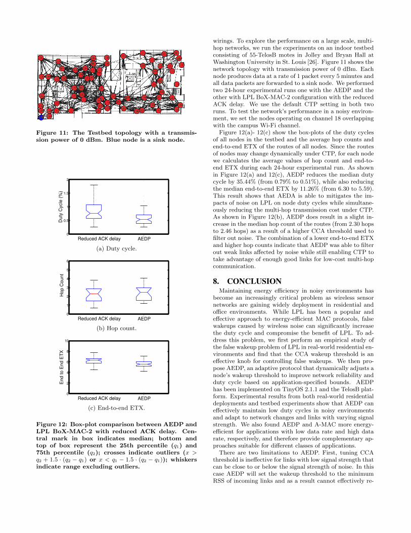
Figure 11: The Testbed topology with a transmis-sion power of 0 dBm. Blue node is a sink node.
0
0.5
1
1.5
2
1 2
Duty
Cyc
le (
%)
Reduced ACK delay AEDP
(a) Duty cycle.
0
1
2
3
4
5
6
1 2
Hop C
ount
Reduced ACK delay AEDP
(b) Hop count.
0
2
4
6
8
10
1 2
End to E
nd E
TX
Reduced ACK delay AEDP
(c) End-to-end ETX.
Figure 12: Box-plot comparison between AEDP andLPL BoX-MAC-2 with reduced ACK delay. Cen-tral mark in box indicates median; bottom andtop of box represent the 25th percentile (q1) and75th percentile (q2); crosses indicate outliers (x >q2 + 1.5 · (q2 − q1) or x < q1 − 1.5 · (q2 − q1)); whiskersindicate range excluding outliers.
wirings. To explore the performance on a large scale, multi-hop networks, we run the experiments on an indoor testbedconsisting of 55-TelosB motes in Jolley and Bryan Hall atWashington University in St. Louis [26]. Figure 11 shows thenetwork topology with transmission power of 0 dBm. Eachnode produces data at a rate of 1 packet every 5 minutes andall data packets are forwarded to a sink node. We performedtwo 24-hour experimental runs one with the AEDP and theother with LPL BoX-MAC-2 configuration with the reducedACK delay. We use the default CTP setting in both tworuns. To test the network’s performance in a noisy environ-ment, we set the nodes operating on channel 18 overlappingwith the campus Wi-Fi channel.
Figure 12(a)- 12(c) show the box-plots of the duty cyclesof all nodes in the testbed and the average hop counts andend-to-end ETX of the routes of all nodes. Since the routesof nodes may change dynamically under CTP, for each nodewe calculates the average values of hop count and end-to-end ETX during each 24-hour experimental run. As shownin Figure 12(a) and 12(c), AEDP reduces the median dutycycle by 35.44% (from 0.79% to 0.51%), while also reducingthe median end-to-end ETX by 11.26% (from 6.30 to 5.59).This result shows that AEDA is able to mitigates the im-pacts of noise on LPL on node duty cycles while simultane-ously reducing the multi-hop transmission cost under CTP.As shown in Figure 12(b), AEDP does result in a slight in-crease in the median hop count of the routes (from 2.30 hopsto 2.46 hops) as a result of a higher CCA threshold used tofilter out noise. The combination of a lower end-to-end ETXand higher hop counts indicate that AEDP was able to filterout weak links affected by noise while still enabling CTP totake advantage of enough good links for low-cost multi-hopcommunication.
8. CONCLUSION
Maintaining energy efficiency in noisy environments hasbecome an increasingly critical problem as wireless sensornetworks are gaining widely deployment in residential andoffice environments. While LPL has been a popular andeffective approach to energy-efficient MAC protocols, falsewakeups caused by wireless noise can significantly increasethe duty cycle and compromise the benefit of LPL. To ad-dress this problem, we first perform an empirical study ofthe false wakeup problem of LPL in real-world residential en-vironments and find that the CCA wakeup threshold is aneffective knob for controlling false wakeups. We then pro-pose AEDP, an adaptive protocol that dynamically adjusts anode’s wakeup threshold to improve network reliability andduty cycle based on application-specified bounds. AEDPhas been implemented on TinyOS 2.1.1 and the TelosB plat-form. Experimental results from both real-world residentialdeployments and testbed experiments show that AEDP caneffectively maintain low duty cycles in noisy environmentsand adapt to network changes and links with varying signalstrength. We also found AEDP and A-MAC more energy-efficient for applications with low data rate and high datarate, respectively, and therefore provide complementary ap-proaches suitable for different classes of applications.
There are two limitations to AEDP. First, tuning CCAthreshold is ineffective for links with low signal strength thatcan be close to or below the signal strength of noise. In thiscase AEDP will set the wakeup threshold to the minimumRSS of incoming links and as a result cannot effectively re-

duce false wakeups caused by noise. This makes AEDP lesseffective for highly sparse networks connected by mostly longlinks. Second, our implementation is specific to the partic-ular CC2420 radio stack used. It is important to develop ageneral methodology — such as the analysis performed inSection 6.2 — to select the key radio and MAC layer pa-rameters. For a new radio stack, developers should firstlymeasure the ACK delay and then tune the duration of CCApolling accordingly. In general, the duration of CCA pollingmust be longer than the ACK delay to avoid false negativesin energy detection which can heavily worsen the perfor-mance. On the other hand, a long energy detection contra-dicts the need for a short, inexpensive energy detection, andarguably even renders the entire check ineffective. There-fore, the duration of CCA polling should be slightly longerthan the ACK delay.
Acknowledgment
The authors thank the anonymous reviewers, and the shep-herd Matteo Ceriotti for their insightful comments. Thiswork was supported in part by NSF under grants CNS-1035773 (CPS) and CNS-1144552 (NeTS).
9. REFERENCES
[1] http://www.tinyos.net/.[2] http://www.contiki-os.org/.[3] http:
//www.zti-telecom.com/EN/LanTrafficV2.html.[4] http://docs.tinyos.net/index.php/CC2420_
Hardware_and_Software_Acks.[5] M. Bertocco, G. Gamba, and A. Sona. Experimental
optimization of CCA thresholds in wireless sensornetworks. In EMC, 2007.
[6] C. A. Boano, T. Voigt, N. Tsiftes, and L. Mottola.Making sensornet mac protocols robust againstinterference. In EWSN, 2010.
[7] M. Z. Brodsky and R. T. Morris. In defense of wirelesscarrier sense. In SIGCOMM, 2009.
[8] M. Buettner, G. V. Yee, E. Anderson, and R. Han.X-mac: a short preamble mac protocol for duty-cycledwireless sensor networks. In SenSys, 2006.
[9] K. K. Chintalapudi and L. Venkatraman. On thedesign of mac protocols for lowlatency hard real-timediscrete control applications over 802.15.4 hardware.In IPSN, 2008.
[10] Crossbow Technology. TelosB mote platform.http://www.xbow.com/Products/Product_pdf_
files/Wireless_pdf/TelosB_Datasheet.pdf.[11] A. Dunkels. The contikimac radio duty cycling
protocol. Technical Report 5128, Swedish Institute ofComputer Science, 2011.
[12] P. Dutta, S. Dawson-Haggerty, Y. Chen, C.-J. M.Liang, and A. Terzis. Design and evaluation of aversatile and efficient receiver-initiated link layer forlow-power wireless. In SenSys, 2010.
[13] P. Dutta, J. Taneja, J. Jeong, X. Jiang, and D. Culler.A building block approach to sensornet systems. InSenSys, 2008.
[14] O. Gnawali, R. Fonseca, K. Jamieson, D. Moss, andP. Levis. Collection tree protocol. In SenSys, 2009.
[15] IEEE. Part 15.4: Wireless Medium Access Control(MAC) and Physical Layer (PHY) Specifications forLow-Rate Wireless Personal Area Networks (WPANs),2006.
[16] A. Kiryushin, A. Sadkov, and A. Mainwaring.Real-world performance of clear channel assessment in802.15.4 wireless sensor networks. In SENSORCOMM,2008.
[17] C.-J. M. Liang, B. Priyantha, J. Liu, and A. Terzis.Surviving wi-fi interference in low power zigbeenetworks. In SenSys, 2010.
[18] D. Moss and P. Levis. BoX-MACs: Exploitingphysical and link layer boundaries in low-powernetworking. Technical Report SING-08-00, StanfordInformation Networks Group, 2008.
[19] J. Polastre, J. Hill, and D. Culler. Versatile low powermedia access for wireless sensor networks. In SenSys,2004.
[20] I. Ramachandran and S. Roy. On the impact of clearchannel assessment on mac performance. InGLOBECOM, 2006.
[21] M. Sha, G. Hackmann, and C. Lu. Energy-efficient lowpower listening for wireless sensor networks in noisyenvironments. Technical Report WUCSE-2011-61,Washington University in St. Louis, 2013.http://cse.wustl.edu/Research/Lists/Technical%
20Reports/Attachments/957/aedp.pdf.[22] K. Srinivasan, P. Dutta, A. Tavakoli, and P. Levis. An
empirical study of low power wireless. In ACMTransactions on Sensor Networks, 2010.
[23] Y. Sun, O. Gurewitz, and D. B. Johnson. Ri-mac: Areceiver-initiated asynchronous duty cycle macprotocol for dynamic traffic loads in wireless sensornetworks. In SenSys, 2008.
[24] Texas Instruments. 2.4 GHz IEEE 802.15.4 /ZigBee-ready RF Transceiver.
[25] Wi-Spy Spectrum Analyzer.http://www.metageek.net/.
[26] WUSTL Wireless Sensor Network Testbed.http://wsn.cse.wustl.edu/index.php/Testbed.
[27] W. Yuan, J.-P. M. G. Linnartz, and I. G. M. M.Niemegeers. Adaptive cca for ieee 802.15.4 wirelesssensor networks to mitigate interference. In WCNC,2010.
[28] M. Zimmerling, F. Ferrari, L. Mottolay, T. Voigty, andL. Thiele. ptunes: Runtime parameter adaptation forlow-power mac protocols. In IPSN, 2012.