enclosures solutions product catalog - farnell element14 · enclosures solutions product catalog...
TRANSCRIPT
Enclosures Solutions
Product Catalog
Rack Cabinets
Rack Accessories
Rackmount Kits
Testmobile Carts
Table
of
Con
ten
ts
One Four
FiveTwo
Three
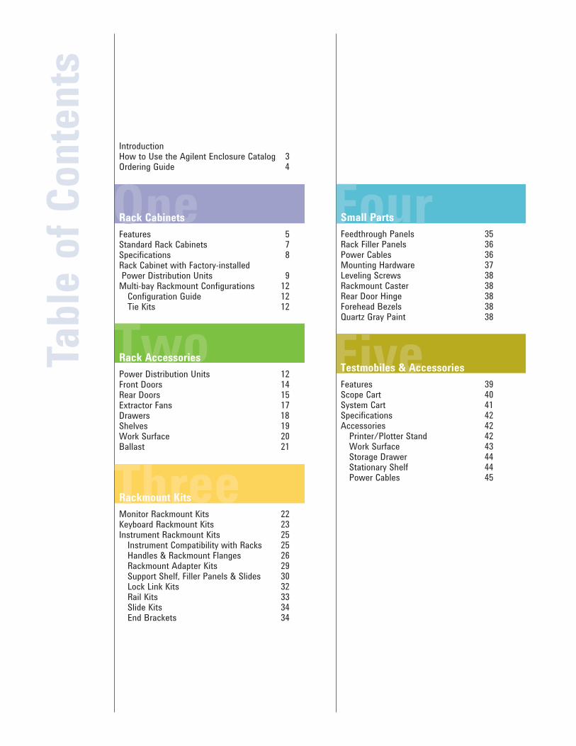
Introduction How to Use the Agilent Enclosure Catalog 3Ordering Guide 4
Rack Cabinets
Features 5Standard Rack Cabinets 7Specifications 8Rack Cabinet with Factory-installed Power Distribution Units 9Multi-bay Rackmount Configurations 12
Configuration Guide 12Tie Kits 12
Rack Accessories
Power Distribution Units 12Front Doors 14Rear Doors 15Extractor Fans 17Drawers 18 Shelves 19Work Surface 20Ballast 21
Rackmount Kits
Monitor Rackmount Kits 22Keyboard Rackmount Kits 23Instrument Rackmount Kits 25
Instrument Compatibility with Racks 25Handles & Rackmount Flanges 26Rackmount Adapter Kits 29Support Shelf, Filler Panels & Slides 30Lock Link Kits 32Rail Kits 33Slide Kits 34End Brackets 34
Small Parts
Feedthrough Panels 35Rack Filler Panels 36Power Cables 36Mounting Hardware 37Leveling Screws 38Rackmount Caster 38Rear Door Hinge 38Forehead Bezels 38Quartz Gray Paint 38
Testmobiles & Accessories
Features 39Scope Cart 40System Cart 41Specifications 42Accessories 42
Printer/Plotter Stand 42Work Surface 43Storage Drawer 44Stationary Shelf 44Power Cables 45
Rack Accessories
3
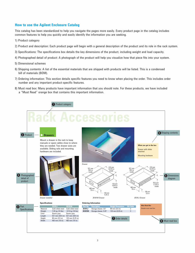
How to use the Agilent Enclosure Catalog
This catalog has been standardized to help you navigate the pages more easily. Every product page in the catalog includes
common features to help you quickly and easily identify the information you are seeking.
1) Product category
2) Product and description: Each product page will begin with a general description of the product and its role in the rack system.
3) Specifications: The specifications box details the key dimensions of the product, including weight and load capacity.
4) Photographed detail of product: A photograph of the product will help you visualize how that piece fits into your system.
5) Dimensional schemes
6) Shipping contents: A list of the essential materials that are shipped with products will be listed. This is a condensed
bill of materials (BOM).
7) Ordering information: This section details specific features you need to know when placing the order. This includes order
number and any important product-specific features.
8) Must read box: Many products have important information that you should note. For these products, we have included
a “Must Read” orange box that contains this important information.
Specifications
35181J 35181M
Material Cold-rolled steel Cold-rolled steel
Weight 7.26 kg (16 lbs) 8.16 kg (18 lbs)
Color Quartz gray Quartz gray
Length 521 mm (20.5 in) 521 mm (20.5 in)
Height 89 mm (3.5 in) 133 mm (5.25 in)
Width 483 mm (19 in) 483 mm (19 in)
What you get in the box
Drawer with slides attached
Mounting hardware
Ordering Information
Part No. Description Height Dimensions EIA Units
35181J Storage drawer, 3.5” 89 mm (3.5 in) 2
35181M Storage drawer, 5.25” 133 mm (5.25 in) 3
35181C Drawer
521 mm20.5 ininside
416 mm16.375 in
inside
79.5 mm3.125 in
inside
89 mm3.5 in
483 mm19 in
521 mm20.5 ininside
416 mm16.375 in
inside
124 mm4.875 in
inside
133 mm5.25 in
483 mm19 in
35181M Drawer 35181J DrawerDrawer installed
Product category
Product
Photographed detail of product
Shipping contents
Order details
Part Specifications
Dimensions diagram
1
2
3
4
6
7
5
Drawers
Mount a drawer in the rack to keep
manuals or spare cables close to where
they are needed. Two drawer sizes are
available. Sliding rails and mounting
hardware are included.
Must read box8
Drawer
Must Read Box
Sample must read box
►

4
Ord
eri
ng
Gu
ide
Agilent’s shipping process includes a worldwide distribution system that allows for
quick delivery and includes a unique flexible shipment program that allows you to
schedule the arrival of your enclosures and better utilize your dock and floor space.
Ordering Guide
Agilent provides a streamlined ordering
system to help you place your order
quickly and easily.
There are three convenient ways to
place an order:
• Your Agilent Field Engineer (see back cover for a list of regional offices or
visit www.agilent.com/find/contactus)
• Agilent call center: In the U.S. call (800) 452-4844 (see back cover for a
list of Agilent call centers).
• Parts ordering (U.S. only): www.parts.agilent.com
Use the following table to map out the
products and parts you need to order for
quick reference.
Description of Product or Part PN# Price
Subtotal
Tax
Total
5
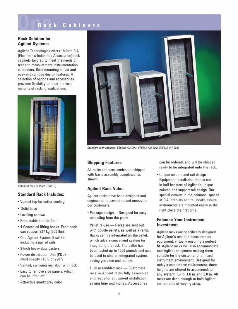
Rack Solution for Agilent Systems
Agilent Technologies offers 19-inch EIA
(Electronics Industries Association) rack
cabinets tailored to meet the needs of
test and measurement instrumentation
customers. Rack mounting is fast and
easy with unique design features. A
selection of options and accessories
provides flexibility to meet the vast
majority of racking applications.
Standard Rack Includes:
• Vented top for better cooling
• Solid base• Leveling screws• Retractable anti-tip foot• 4 Concealed lifting hooks. Each hook
can support 227 kg (500 lbs).
• One Agilent System II rail kit, including a pair of rails.
• 3-Inch heavy duty casters• Power distribution Unit (PDU) –
must specify 110 V or 220 V• Vented, swinging rear door with lock• Easy to remove side panels, which
can be lifted off
• Attractive quartz gray color
Shipping Features
All racks and accessories are shipped
with basic assembly completed, as
shown.
Agilent Rack Value
Agilent racks have been designed and
engineered to save time and money for
our customers:
• Package design —Designed for easy unloading from the pallet.
• Pallet re-use — Racks are sent out with double pallets, as well as a ramp.
Racks can be integrated on the pallet,
which adds a convenient system for
integrating the rack. The pallet has
been tested up to 1000 pounds and can
be used to ship an integrated system,
saving you time and money.
• Fully assembled rack — Customers receive Agilent racks fully assembled
and ready for equipment installation
saving time and money. Accessories
can be ordered, and will be shipped
ready to be integrated onto the rack.
• Unique column and rail design — Equipment installation time is cut
in half because of Agilent’s unique
column and support rail design. Our
special cutouts in the columns, spaced
at EIA intervals and rail hooks assure
instruments are mounted easily in the
right place the first time!
Enhance Your Instrument Investment
Agilent racks are specifically designed
for Agilent’s test and measurement
equipment, virtually ensuring a perfect
fit. Agilent racks will also accommodate
non-Agilent equipment making them
suitable for the customer of a mixed
instrument environment. Designed for
today’s competitive environment, three
heights are offered to accommodate
any system: 1.3 m, 1.6 m, and 2.0 m. All
racks are deep enough to hold Agilent
instruments of varying sizes.
Standard rack cabinets: E3661B (32 EIA), E7590A (25 EIA), E3662B (41 EIA)
Standard rack cabinet (E3661B)
OneR a c k C a b i n e t s
6
Load a Rack in Less Time
The design of Agilent support rails
can cut in half the time required to
install equipment in a rack. The rails
hang on discrete slots on the vertical
mounting columns, corresponding
to each EIA unit in the rack. Vertical adjustment between instruments is
minimized by selecting the proper rail.
Rails are available for Agilent System II
instruments and for flat bottom instru-
ment chassis (see page 34). The system
was specifically designed to minimize
the time required to install instruments.
Rack Systems Fast and Easily
Racks are shipped with all basic materials
assembled. No time is lost preparing a
rack with basic assembly. Accessories,
kits and supplementary small parts are
shipped separately, as ordered, and are
ready for immediate configuration.
More than just a way of storing
instruments, the racks reflect Agilent’s
reputation for quality and design. A
sturdy frame provides structural integrity,
which allows lightweight, easy-to-lift off
side panels that allow for installation
and easy access to equipment and
cables. Rails are placed into keyed slots
in the vertical columns, resulting in quick
and accurate positioning.
Use Vertical Space Efficiently
Vertical space within a rack is measured in industry-standard EIA units, where
1 EIA unit = 1.75 inches (44.5 mm).
Equipment height is also specified
in EIA units. System configuration is
made easier by counting EIA units from
the base of the rack. A seamless fit of
instrument and rail is ensured.
Manage Power Requirements
A power management system must be
ordered. Option AW3 (110 V) or option AW5 (220 V). It is vertically mounted behind the rack rear column and supplies
power to the cabinet. An illuminated
master switch, which is conveniently
located on the front of the rack, provides
easy access to turn the power on
and off to the Power Distribution Unit
(PDU) outlets.
To completely remove power from the
PDU and the rack system, the PDU
power cord needs to be removed from
the premise electrical system, or if the
rack system is connected to a dedicated
circuit breaker, the breaker needs to be
opened.
Protect from Heat Buildup
It is important for racks to efficiently
dispose of heat. Instruments increasingly
generate more heat, and in a compact
rackmounted system the heat buildup
can be detrimental to the system.
System-generated heat is removed by
natural convection through a ventilation
path incorporated in the roof of the
racks. The vented rear door also helps
reduce the heat captured within the rack.
For greater heat dissipation, an optional
easy to install top-mounted extractor fan
is available. (see page 17)
Secure Instruments During Test
Both the rear door and the optional
Plexiglas front door can be locked
to secure against disruption of tests
or unauthorized removal of system
components. The symmetrical rear
door design allows it to be mounted for
opening to either left or right, useful for
multi-bay configurations.
Move Racks Easily
Each rack is provided with four 3-inch
diameter, smooth-rolling, heavy-duty
casters to facilitate moving racks over
short distances. Four lifting hooks
conveniently concealed in the top of the
rack allow for transport, even when fully
loaded. Each hook can support 227 kg
(500 lbs) to easily handle the maximum
recommended gross weight for a loaded
rack of 816 kg (1800 lbs).
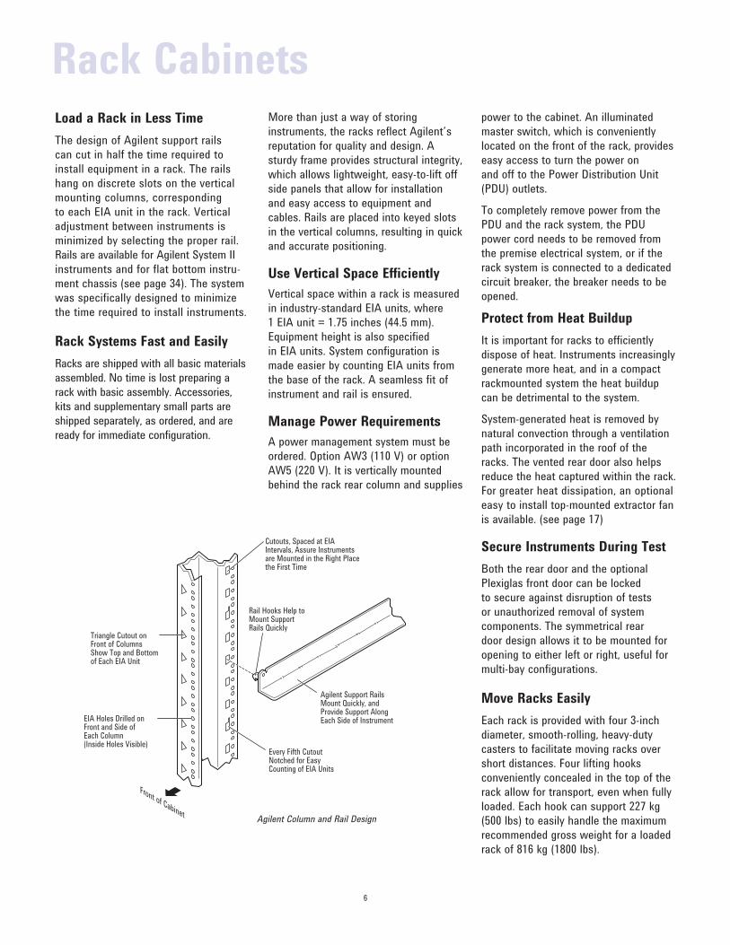
Front of Cabinet
Triangle Cutout on Front of Columns Show Top and Bottomof Each EIA Unit
Every Fifth CutoutNotched for EasyCounting of EIA Units
Agilent Support RailsMount Quickly, and Provide Support Along Each Side of InstrumentEIA Holes Drilled on
Front and Side of Each Column(Inside Holes Visible)
Rail Hooks Help toMount SupportRails Quickly
Cutouts, Spaced at EIAIntervals, Assure Instrumentsare Mounted in the Right Placethe First Time
Rack Cabinets
Agilent Column and Rail Design
Lifting Hook
BlankForehead
Bezel
RearVerticalColumn
PDU(optional)
Vented Top
Vented,Lockable Rear Door
Anti-tip Foot CosmeticBase Cover
LevelingScrew
Caster Removable,Light-weight Side Panel
RearDoorHinge
Front VerticalColumn
Space Reservedfor Extractor Fan
7
Enhance Stability
A front mounted retractable anti-tip
stabilizer that can be extended into place
with ease is standard on all racks. It
provides temporary anti-tip capability for
slide mounted products when they are in
their extended position. Use the optional
anti-tip ballast kit when permanent anti-
tip capability is desired.
Improve Cable Management
Agilent racks, including the 1.3 m, 1.6 m
and 2.0 m, have an additional 100 mm
of internal space that is available at
the rear of the rack. This convenient
space is available for the installation of
power distribution units (PDUs) and as a
convenient location for cables, which are
routed out the bottom of the rack. The
added rear space also enhances air flow.
Ventilation
Agilent standard racks include a vented
top cap and 100 mm additional internal
rear space enhancing air flow.
Material
Frame/columns: 13 Ga. cold rolled steel.
Side Panels: 18 Ga. cold rolled steel.
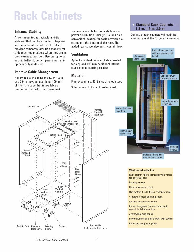
What you get in the box
Rack cabinet (fully assembled) with vented top cover & bezel
Leveling screws
Retractable anti-tip foot
One system II rail kit (pair of Agilent rails)
4 integral concealed lifting hooks.
4 3-inch heavy duty casters
Factory integrated (to your order) with vented, lockable rear door
2 removable side panels
Power distribution unit & bezel with switch
Re-usable integration pallet
Standard Rack Cabinets — 1.3 m, 1.6 m, 2.0 m
Our line of rack cabinets will optimize
your storage ability for your instruments.
▲
Optional forehead bezel with switch connected to PDU4 Concealed
Lifting Hooks
Vented, Lockable Rear Door
Standard Anti-tip Foot Extends from Bottom
Leveling Screws
Easily Removable Side Panels
Optional Power Distribution Strips
Exploded View of Standard Rack
3 Inch, Heavy Duty Casters
Rack Cabinets
8
Rack Specifications
Casters Rating 318 kg (700 lbs) each, 816 kg (1800 lbs) total
Casters have a point contact convex cross section
Lift Hook Rating 227 kg (500 lbs) each
Total system and cabinet weight is a maximum 816 kg (1800 lbs), static.
Lift cabinet using all four (4) hooks.
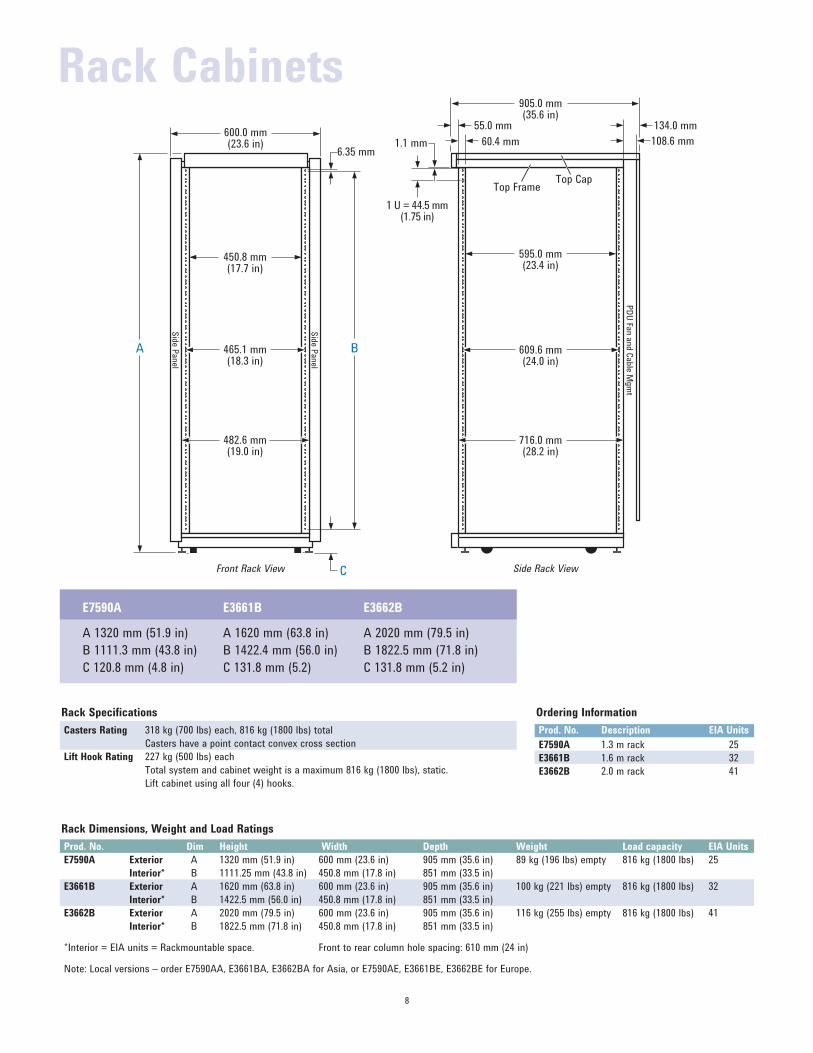
Rack Dimensions, Weight and Load Ratings
Prod. No. Dim Height Width Depth Weight Load capacity EIA Units
E7590A Exterior A 1320 mm (51.9 in) 600 mm (23.6 in) 905 mm (35.6 in) 89 kg (196 lbs) empty 816 kg (1800 lbs) 25
Interior* B 1111.25 mm (43.8 in) 450.8 mm (17.8 in) 851 mm (33.5 in)
E3661B Exterior A 1620 mm (63.8 in) 600 mm (23.6 in) 905 mm (35.6 in) 100 kg (221 lbs) empty 816 kg (1800 lbs) 32
Interior* B 1422.5 mm (56.0 in) 450.8 mm (17.8 in) 851 mm (33.5 in)
E3662B Exterior A 2020 mm (79.5 in) 600 mm (23.6 in) 905 mm (35.6 in) 116 kg (255 lbs) empty 816 kg (1800 lbs) 41
Interior* B 1822.5 mm (71.8 in) 450.8 mm (17.8 in) 851 mm (33.5 in)
*Interior = EIA units = Rackmountable space. Front to rear column hole spacing: 610 mm (24 in)
Note: Local versions – order E7590AA, E3661BA, E3662BA for Asia, or E7590AE, E3661BE, E3662BE for Europe.
Ordering Information
Prod. No. Description EIA Units
E7590A 1.3 m rack 25
E3661B 1.6 m rack 32
E3662B 2.0 m rack 41
B
600.0 mm(23.6 in)
482.6 mm(19.0 in)
450.8 mm(17.7 in)
6.35 mm
C
Sid
e P
anel
Sid
e P
anel
A 465.1 mm(18.3 in)
905.0 mm(35.6 in)
609.6 mm(24.0 in)
716.0 mm(28.2 in)
PD
U Fa
n a
nd C
able
Mgm
t
595.0 mm(23.4 in)
60.4 mm 108.6 mm1.1 mm
1 U = 44.5 mm(1.75 in)
Top CapTop Frame
134.0 mm55.0 mm
E7590A
A 1320 mm (51.9 in)
B 1111.3 mm (43.8 in)
C 120.8 mm (4.8 in)
E3661B
A 1620 mm (63.8 in)
B 1422.4 mm (56.0 in)
C 131.8 mm (5.2)
E3662B
A 2020 mm (79.5 in)
B 1822.5 mm (71.8 in)
C 131.8 mm (5.2 in)
Front Rack View Side Rack View
Rack Cabinets
9
What you get in the box
Rack cabinet (assembled with vented, lockable rear door,
2 removable side panels, vented top, solid base)
Leveling screws
Retractable anti-tip foot
4 3-inch heavy duty casters
One System II rail kit (one set of Agilent instrument rails)
Factory installed PDU (110 V option AW3 or 220 V option AW5)
Forehead bezel with lighted safety switch
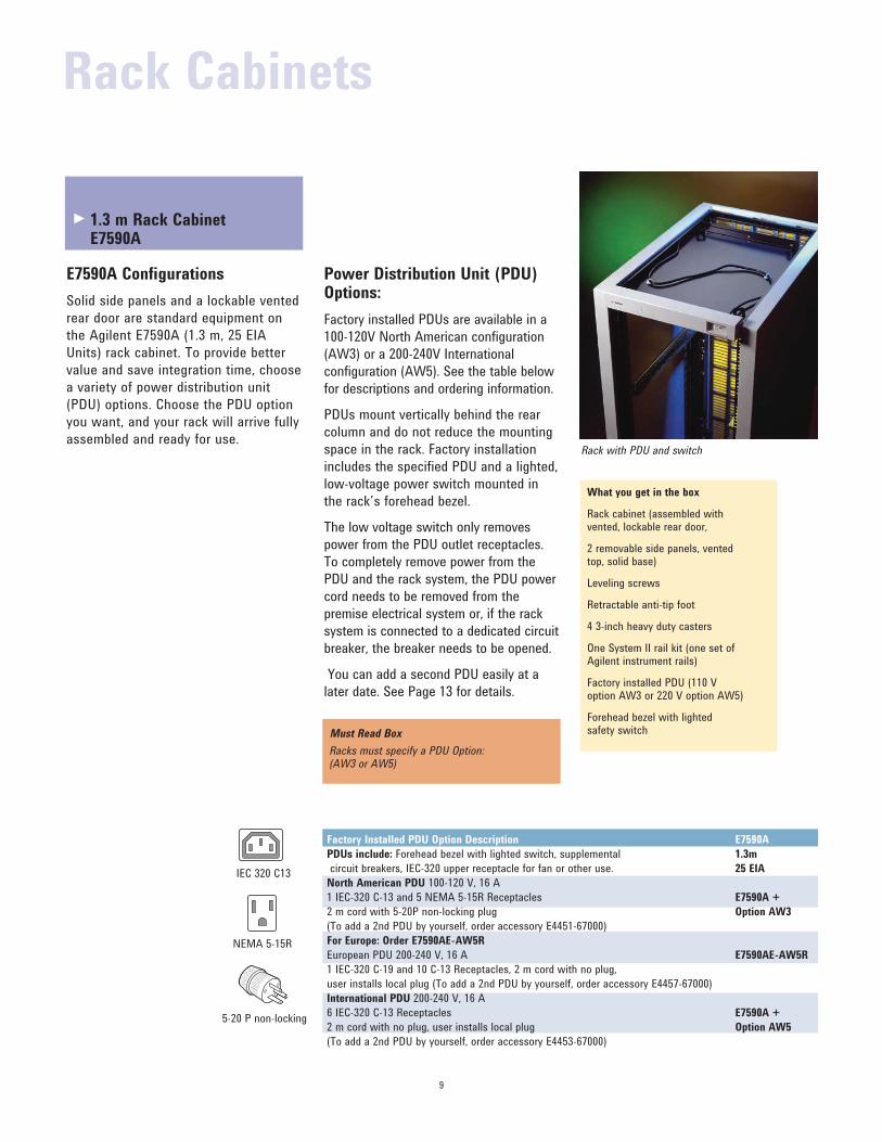
Rack with PDU and switch
E7590A Configurations
Solid side panels and a lockable vented
rear door are standard equipment on
the Agilent E7590A (1.3 m, 25 EIA
Units) rack cabinet. To provide better
value and save integration time, choose
a variety of power distribution unit
(PDU) options. Choose the PDU option
you want, and your rack will arrive fully
assembled and ready for use.
Power Distribution Unit (PDU) Options:
Factory installed PDUs are available in a
100-120V North American configuration (AW3) or a 200-240V International configuration (AW5). See the table below
for descriptions and ordering information.
PDUs mount vertically behind the rear
column and do not reduce the mounting
space in the rack. Factory installation
includes the specified PDU and a lighted,
low-voltage power switch mounted in
the rack’s forehead bezel.
The low voltage switch only removes
power from the PDU outlet receptacles.
To completely remove power from the
PDU and the rack system, the PDU power
cord needs to be removed from the
premise electrical system or, if the rack
system is connected to a dedicated circuit
breaker, the breaker needs to be opened.
You can add a second PDU easily at a later date. See Page 13 for details.
Must Read Box
Racks must specify a PDU Option: (AW3 or AW5)
Factory Installed PDU Option Description E7590A
PDUs include: Forehead bezel with lighted switch, supplemental 1.3m
circuit breakers, IEC-320 upper receptacle for fan or other use. 25 EIA
North American PDU 100-120 V, 16 A 1 IEC-320 C-13 and 5 NEMA 5-15R Receptacles E7590A +
2 m cord with 5-20P non-locking plug Option AW3
(To add a 2nd PDU by yourself, order accessory E4451-67000)
For Europe: Order E7590AE-AW5R
European PDU 200-240 V, 16 A E7590AE-AW5R
1 IEC-320 C-19 and 10 C-13 Receptacles, 2 m cord with no plug,
user installs local plug (To add a 2nd PDU by yourself, order accessory E4457-67000)
International PDU 200-240 V, 16 A 6 IEC-320 C-13 Receptacles E7590A +
2 m cord with no plug, user installs local plug Option AW5
(To add a 2nd PDU by yourself, order accessory E4453-67000)
IEC 320 C13
NEMA 5-15R
5-20 P non-locking
1.3 m Rack Cabinet E7590A
Rack Cabinets
►
10
E3661B
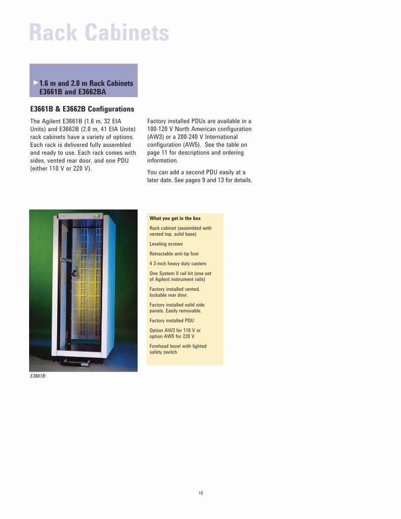
What you get in the box
Rack cabinet (assembled with vented top, solid base)
Leveling screws
Retractable anti-tip foot
4 3-inch heavy duty casters
One System II rail kit (one set of Agilent instrument rails)
Factory installed vented, lockable rear door.
Factory installed solid side panels. Easily removable.
Factory installed PDU
Option AW3 for 110 V or option AW5 for 220 V
Forehead bezel with lighted safety switch
E3661B & E3662B Configurations
The Agilent E3661B (1.6 m, 32 EIA
Units) and E3662B (2.0 m, 41 EIA Units)
rack cabinets have a variety of options.
Each rack is delivered fully assembled
and ready to use. Each rack comes with
sides, vented rear door, and one PDU
(either 110 V or 220 V).
Factory installed PDUs are available in a
100-120 V North American configuration (AW3) or a 200-240 V International configuration (AW5). See the table on
page 11 for descriptions and ordering
information.
You can add a second PDU easily at a later date. See pages 9 and 13 for details.
1.6 m and 2.0 m Rack Cabinets E3661B and E3662BA
Rack Cabinets
►

11
1.6 m and 2.0 m Rack Cabinets E3661B and E3662B
Description of Factory Installed Options E3661B* E3662B*
PDUs include: Forehead bezel with lighted switch, 1.6 m 32 EIA 2.0 m 41 EIA
dual circuit breakers, IEC-320 upper receptacle for
fan or other use.
North American PDU 100-120 V, 15 A 1 IEC-320 C-13 and 9 NEMA 5-15R Receptacles, 2 m cord E3661B + E3662B +
with 5-20 P non-locking plug Option AW3 Option AW3
(To add a 2nd PDU by yourself, order accessory E4455-67000)
For Europe: Order E3661BE-AW5R or E3662BE-AW5R
European PDU 200-240 V, 15 A 1 IEC-320 C-19 and 10 C-13 Receptacles, 2 m cord E3661BE-AW5R E3662BE-AW5R
with no plug, user installs local plug
(To add a 2nd PDU by yourself, order accessory E4457-67000)
International PDU 200-240 V, 15 A 1 IEC-320 C-19 and 10 C-13 Receptacles, 2 m cord with E3661B + E3662B +
no plug, user installs local plug Option AW5 Option AW5
(To add a 2nd PDU by yourself, order accessory E4457-67000)
IEC-320 C13
IEC-320 C19
NEMA 5-15R
5-20 P non-locking
Must read box
E3661B & E3662B Racks require one option
PDU option
(AW3 or AW5)
Configuration Examples
Rack with sides, rear door and PDU (100-120 V) :
model + AW3 (100-120V PDU)
Rack with sides, rear door and PDU (200-220 V) :
model + AW5 (200-240 V PDU)
Agilent Power Distribution Options
Rack Model Ht. (m) EIA Units
AW3 – 100-120 V US plug AW5 – 200-220 V no plug Must choose one
E3662B 2.0 41 AW3 AW5
E3661B 1.6 32 AW3 AW5
Contacting Agilent Regional Offices &
Call Centers: See the back cover of this
catalog for a list of local and regional
sales offices near you.
On the Worldwide Web:
www.agilent.com/find/contactus
For additional information on racks
please visit our web site:
www.agilent.com/find/enclosures
Ordering Parts:
www.parts.agilent.com
*NOTE: order option AW1 for a rack
with no sides, rear door, or PDU.
If AW1 is ordered, then the
accessories must be purchased
and installed separately.
Rack Cabinets►
12
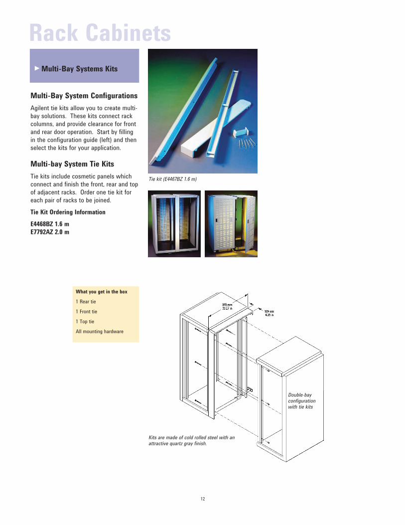
What you get in the box
1 Rear tie
1 Front tie
1 Top tie
All mounting hardware
Tie kit (E4467BZ 1.6 m)
Double-bay configuration with tie kits
Multi-Bay System Configurations
Agilent tie kits allow you to create multi-
bay solutions. These kits connect rack
columns, and provide clearance for front
and rear door operation. Start by filling
in the configuration guide (left) and then
select the kits for your application.
Multi-bay System Tie Kits
Tie kits include cosmetic panels which
connect and finish the front, rear and top
of adjacent racks. Order one tie kit for
each pair of racks to be joined.
Tie Kit Ordering Information
E4468BZ 1.6 m
E7792AZ 2.0 m
Kits are made of cold rolled steel with an attractive quartz gray finish.
Multi-Bay Systems Kits
Rack Cabinets
►
13
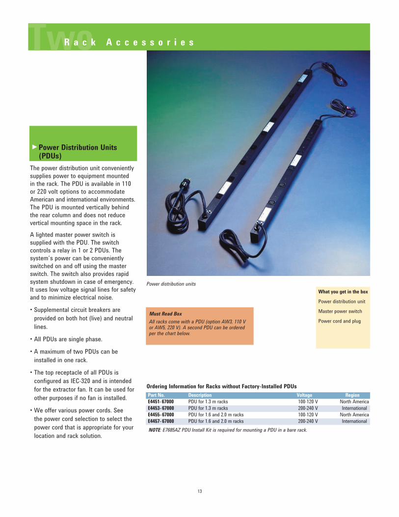
Power Distribution Units (PDUs)
The power distribution unit conveniently
supplies power to equipment mounted
in the rack. The PDU is available in 110
or 220 volt options to accommodate
American and international environments.
The PDU is mounted vertically behind
the rear column and does not reduce
vertical mounting space in the rack.
A lighted master power switch is
supplied with the PDU. The switch
controls a relay in 1 or 2 PDUs. The
system’s power can be conveniently
switched on and off using the master
switch. The switch also provides rapid
system shutdown in case of emergency.
It uses low voltage signal lines for safety
and to minimize electrical noise.
• Supplemental circuit breakers are provided on both hot (live) and neutral
lines.
• All PDUs are single phase.
• A maximum of two PDUs can be installed in one rack.
• The top receptacle of all PDUs is configured as IEC-320 and is intended
for the extractor fan. It can be used for
other purposes if no fan is installed.
• We offer various power cords. See the power cord selection to select the
power cord that is appropriate for your
location and rack solution.
What you get in the box
Power distribution unit
Master power switch
Power cord and plug
Ordering Information for Racks without Factory-Installed PDUs
Part No. Description Voltage Region
E4451-67000 PDU for 1.3 m racks 100-120 V North AmericaE4453-67000 PDU for 1.3 m racks 200-240 V InternationalE4455-67000 PDU for 1.6 and 2.0 m racks 100-120 V North AmericaE4457-67000 PDU for 1.6 and 2.0 m racks 200-240 V International
Must Read Box
All racks come with a PDU (option AW3, 110 V or AW5, 220 V). A second PDU can be ordered per the chart below.
Power distribution units
TwoR a c k A c c e s s o r i e s
NOTE: E7685AZ PDU Install Kit is required for mounting a PDU in a bare rack.
►
14
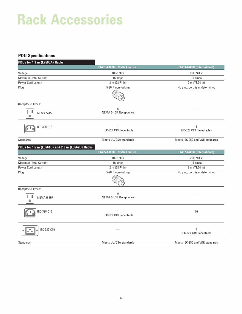
PDU Specifications
PDUs for 1.3 m (E7590A) Racks
E4451-67000 (North America) E4453-67000 (International)
Voltage 100-120 V 200-240 VMaximum Total Current 15 amps 15 amps
Power Cord Length 2 m (78.74 in) 2 m (78.74 in)
Plug 5-20 P non-locking No plug; cord is undetermined
Receptacle Types:
5 — NEMA 5-15R Receptacles
1 6 IEC-320 C13 Receptacle IEC-320 C13 Receptacles
Standards Meets UL/CSA standards Meets IEC-950 and VDE standards
PDUs for 1.6 m (E3661B) and 2.0 m (E3662B) Racks
E4455-67000 (North America) E4457-67000 (International)
Voltage 100-120 V 200-240 VMaximum Total Current 15 amps 15 amps
Power Cord Length 2 m (78.74 in) 2 m (78.74 in)
Plug 5-20 P non-locking No plug; cord is undetermined
Receptacle Types:
9 — NEMA 5-15R Receptacles
1 10 IEC-320 C13 Receptacle
— 1 IEC-320 C19 Receptacle
Standards Meets UL/CSA standards Meets IEC-950 and VDE standards
NEMA 5-15R
IEC-320 C13
NEMA 5-15R
IEC-320 C13
IEC-320 C19
Rack Accessories
15
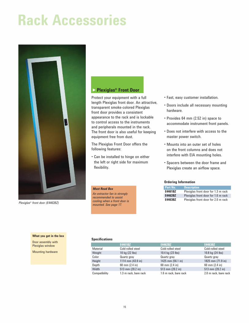
Plexiglas® Front Door
Protect your equipment with a full
length Plexiglas front door. An attractive,
transparent smoke-colored Plexiglas
front door provides a consistent
appearance to the rack and is lockable
to control access to the instruments
and peripherals mounted in the rack.
The front door is also useful for keeping
equipment free from dust.
The Plexiglas Front Door offers the
following features:
• Can be installed to hinge on either the left or right side for maximum
flexibility.
Specifications
E4461BZ E4462BZ E4463BZ
Material Cold-rolled steel Cold-rolled steel Cold-rolled steel
Weight 10 kg (22 lbs) 10.4 kg (23 lbs) 10.8 kg (24 lbs)
Color Quartz gray Quartz gray Quartz gray
Height 1114 mm (43.9 in) 1425 mm (56.1 in) 1825 mm (71.9 in)
Depth 60 mm (2.4 in) 60 mm (2.4 in) 60 mm (2.4 in)
Width 513 mm (20.2 in) 513 mm (20.2 in) 513 mm (20.2 in)
Compatibility 1.3 m rack, bare rack 1.6 m rack, bare rack 2.0 m rack, bare rack
What you get in the box
Door assembly with Plexiglas window
Mounting hardware
Ordering Information
Part No. Description
E4461BZ Plexiglas front door for 1.3 m rack
E4462BZ Plexiglas front door for 1.6 m rack
E4463BZ Plexiglas front door for 2.0 m rack
• Fast, easy customer installation.
• Doors include all necessary mounting hardware.
• Provides 64 mm (2.52 in) space to accommodate instrument front panels.
• Does not interfere with access to the master power switch.
• Mounts into an outer set of holes on the front columns and does not
interfere with EIA mounting holes.
• Spacers between the door frame and Plexiglas create an airflow space.
Must Read Box
An extractor fan is strongly recommended to assist cooling when a front door is mounted. See page 17.
Plexiglas® front door (E4462BZ)
Rack Accessories
►
16
What you get in the box
1 Solid rear door
1 Latch catch
Mounting hardware
What you get in the box
1 Vented rear door
1 Latch catch
Mounting hardware
Specifications – Solid Rear Doors
E4476-67000 E4478-67000
Material Cold-rolled steel Cold-rolled steel
Weight 15.4 kg (34 lbs) 21.3 kg (47 lbs)
Color Quartz gray Quartz gray
Height 1425.6 mm (57.2 in) 1852.7 mm (72.9 in)
Width 599 mm (23.6 in) 599 mm (23.6 in)
EIA Units 32 41
Compatibility 1.6 m rack, bare rack 2.0 m rack, bare rack
Ordering Information – Solid Rear Doors
Part No. Description
E4476-67000 Solid rear door for 1.6 m rack
E4478-67000 Solid rear door for 2.0 m rack
Specifications – Vented Rear Doors
E4477-67000 E4479-67000
Material Cold-rolled steel Cold-rolled steel
Weight 14.1 kg (31 lbs) 20 kg (44 lbs)
Color Quartz gray Quartz gray
Height 1425.6 mm (57.2 in) 1852.7 mm (72.9 in)
Width 599 mm (23.6 in) 599 mm (23.6 in)
EIA Units 32 41
Compatibility 1.6 m rack, bare rack 2.0 m rack, bare rack
Ordering Information – Vented Rear Doors
Part No. Description
E4477-67000 Vented rear door for 1.6 m rackE4479-67000 Vented rear door for 2.0 m rack
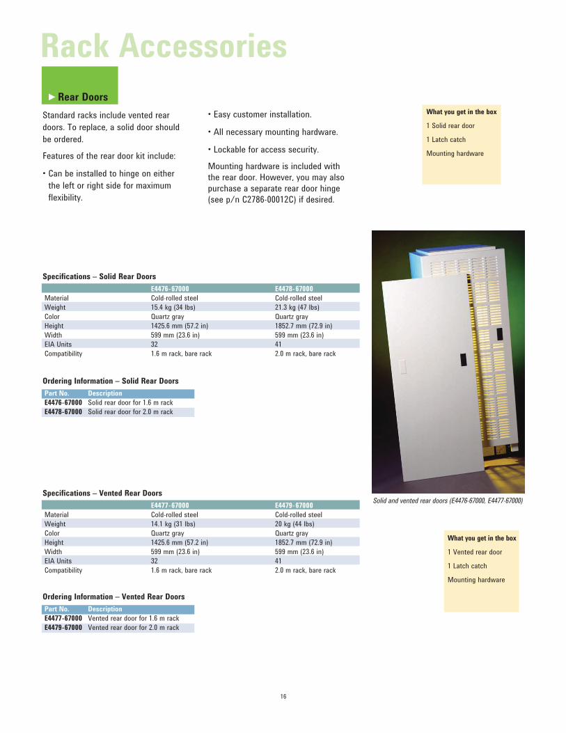
Rear Doors
Standard racks include vented rear
doors. To replace, a solid door should
be ordered.
Features of the rear door kit include:
• Can be installed to hinge on either the left or right side for maximum
flexibility.
• Easy customer installation.
• All necessary mounting hardware.
• Lockable for access security.
Mounting hardware is included with
the rear door. However, you may also
purchase a separate rear door hinge
(see p/n C2786-00012C) if desired.
Solid and vented rear doors (E4476-67000, E4477-67000)
Rack Accessories
►

447 mm17.6 in
150 mm5.91 in
56 mm2.2 in
17
Ordering Information
Part No. Description
E4470AZ 100/120 V 200 cfm extractor fan, fits all racks
E4471AZ 200/240 V 200 cfm extractor fan, fits all racks
What you get in the box
1 Fan
Mounting hardware
Extractor Fans – 200 cfm
Extractor fans are used to increase air
flow through the rack cabinet. Agilent’s
fan improves natural convection cooling
by increasing the airflow in the rack.
Use of the fan enhances the movement
of warm air from the bottom of the rack
up and out through the vented top cap,
providing cooling to the entire length of
the rack.
The customer installable extractor fan
mounts easily under the top cap into
the top frame of the rack. It moves air
at 342 cubic meters per hour (200 cubic
feet per minute). The fan does not reduce
the space available for rackmounting
instruments.
• Use when rack internal temperatures are 15°C (27°F) above ambient.
• Fans are highly recommended for racks with a front door.
• One fan per rack.
• Select an appropriate fan that fits your local AC voltage.
• Fans plug into the upper IEC 320 outlet on PDU.
Specifications
E4470AZ/E4471AZ (200 cfm)
Airflow 200 cfm (342 cmh)
Acoustic noise 43 dB
AC input 100/120 V or 200/240 V (50-60 Hz)AC current 1 ampere maximum
E4470AZ/4471AZ
Material Cold-rolled steel
Weight 3.6 kg (8 lbs)
Color Quartz gray
Length 150 mm (5.91 in)
Height 56 mm (2.2 in)
Width 447 mm (17.6 in)
Extractor fan installed in rack
Extractor fan assembly (E4470AZ)
Rack Accessories
►
18
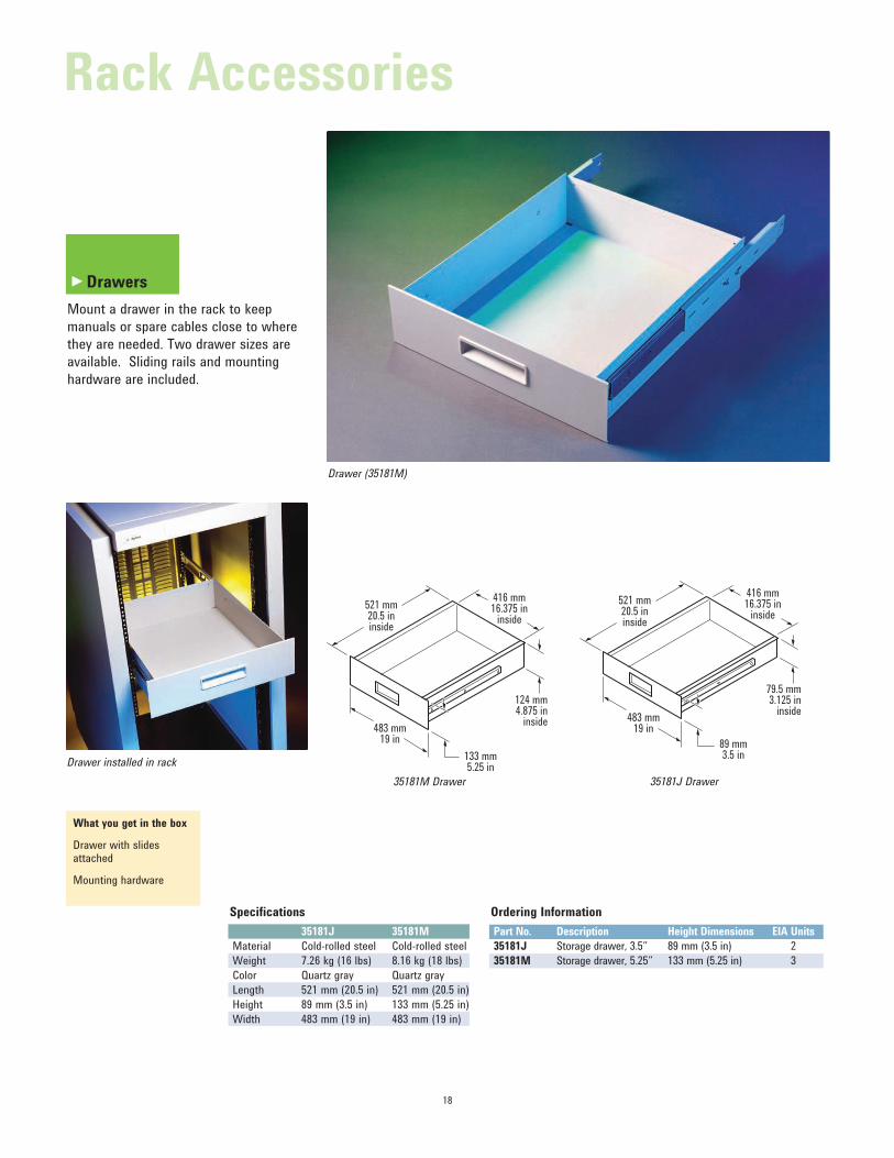
Drawers
Mount a drawer in the rack to keep
manuals or spare cables close to where
they are needed. Two drawer sizes are
available. Sliding rails and mounting
hardware are included.
Specifications
35181J 35181M
Material Cold-rolled steel Cold-rolled steel
Weight 7.26 kg (16 lbs) 8.16 kg (18 lbs)
Color Quartz gray Quartz gray
Length 521 mm (20.5 in) 521 mm (20.5 in)
Height 89 mm (3.5 in) 133 mm (5.25 in)
Width 483 mm (19 in) 483 mm (19 in)
What you get in the box
Drawer with slides attached
Mounting hardware
Ordering Information
Part No. Description Height Dimensions EIA Units
35181J Storage drawer, 3.5” 89 mm (3.5 in) 2
35181M Storage drawer, 5.25” 133 mm (5.25 in) 3
35181C Drawer
521 mm20.5 ininside
416 mm16.375 in
inside
79.5 mm3.125 in
inside
89 mm3.5 in
483 mm19 in
521 mm20.5 ininside
416 mm16.375 in
inside
124 mm4.875 in
inside
133 mm5.25 in
483 mm19 in
35181M Drawer 35181J Drawer
Drawer installed in rack
Drawer (35181M)
Rack Accessories
►
19
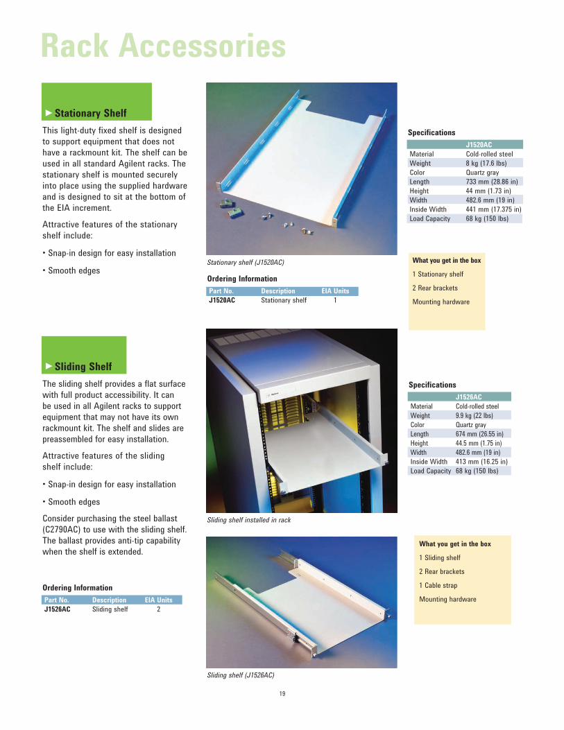
Stationary Shelf
This light-duty fixed shelf is designed
to support equipment that does not
have a rackmount kit. The shelf can be
used in all standard Agilent racks. The
stationary shelf is mounted securely
into place using the supplied hardware
and is designed to sit at the bottom of
the EIA increment.
Attractive features of the stationary
shelf include:
• Snap-in design for easy installation
• Smooth edges
Specifications
J1520AC
Material Cold-rolled steel
Weight 8 kg (17.6 lbs)
Color Quartz gray
Length 733 mm (28.86 in)
Height 44 mm (1.73 in)
Width 482.6 mm (19 in)
Inside Width 441 mm (17.375 in)
Load Capacity 68 kg (150 lbs)
What you get in the box
1 Stationary shelf
2 Rear brackets
Mounting hardware
Ordering Information
Part No. Description EIA Units
J1520AC Stationary shelf 1
Sliding Shelf
The sliding shelf provides a flat surface
with full product accessibility. It can
be used in all Agilent racks to support
equipment that may not have its own
rackmount kit. The shelf and slides are
preassembled for easy installation.
Attractive features of the sliding
shelf include:
• Snap-in design for easy installation
• Smooth edges
Consider purchasing the steel ballast
(C2790AC) to use with the sliding shelf.
The ballast provides anti-tip capability
when the shelf is extended.
Specifications
J1526AC
Material Cold-rolled steel
Weight 9.9 kg (22 lbs)
Color Quartz gray
Length 674 mm (26.55 in)
Height 44.5 mm (1.75 in)
Width 482.6 mm (19 in)
Inside Width 413 mm (16.25 in)
Load Capacity 68 kg (150 lbs)
What you get in the box
1 Sliding shelf
2 Rear brackets
1 Cable strap
Mounting hardware
Ordering Information
Part No. Description EIA Units
J1526AC Sliding shelf 2
Sliding shelf installed in rack
Stationary shelf (J1520AC)
Sliding shelf (J1526AC)
Rack Accessories
►
►
20
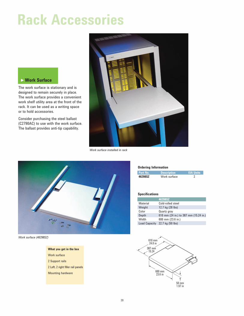
Work Surface
The work surface is stationary and is
designed to remain securely in place.
The work surface provides a convenient
work shelf utility area at the front of the
rack. It can be used as a writing space
or to hold accessories.
Consider purchasing the steel ballast
(C2790AC) to use with the work surface.
The ballast provides anti-tip capability.
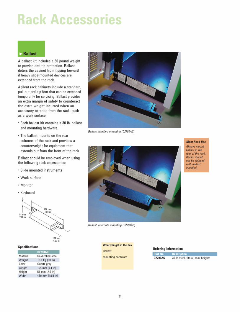
Specifications
46298SZ
Material Cold-rolled steel
Weight 12.7 kg (28 lbs)
Color Quartz gray
Depth 610 mm (24 in.) to 387 mm (15.24 in.)
Width 600 mm (23.6 in.)
Load Capacity 22.7 kg (50 lbs)
What you get in the box
Work surface
2 Support rails
2 Left, 2 right filler rail panels
Mounting hardware
Ordering Information
Part No. Description EIA Units
46298SZ Work surface 2
610 mm24.0 in
600 mm23.6 in
387 mm15.24
50 mm1.97 in
Work surface installed in rack
Work surface (46298SZ)
Rack Accessories
►
21
Ordering Information
Part No. Description
C2790AC 30 lb steel, fits all rack heights
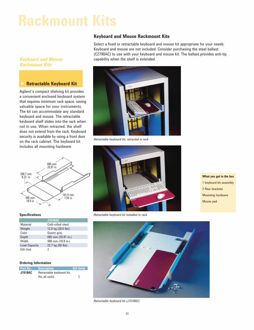
Ballast
A ballast kit includes a 30 pound weight
to provide anti-tip protection. Ballast
deters the cabinet from tipping forward
if heavy slide-mounted devices are
extended from the rack.
Agilent rack cabinets include a standard,
pull-out anti-tip foot that can be extended
temporarily for servicing. Ballast provides
an extra margin of safety to counteract
the extra weight incurred when an
accessory extends from the rack, such
as a work surface.
• Each ballast kit contains a 30 lb. ballast and mounting hardware.
• The ballast mounts on the rear columns of the rack and provides a
counterweight for equipment that
extends out from the front of the rack.
Ballast should be employed when using
the following rack accessories:
• Slide mounted instruments
• Work surface
• Monitor
• Keyboard
Specifications
C2790AC
Material Cold-rolled steel
Weight 13.6 kg (30 lb)
Color Quartz gray
Length 104 mm (4.1 in)
Height 51 mm (2.0 in)
Width 480 mm (18.9 in)
What you get in the box
Ballast
Mounting hardware
Must Read Box
Always mount ballast in the rear of the rack. Racks should not be shipped with ballast installed.
104 mm4.09 in
480 mm18.9 in
51 mm2.00 in
Ballast standard mounting (C2790AC)
Ballast, alternate mounting (C2790AC)
Rack Accessories
►

22
Monitor Rackmount Kit
Safely and securely install your monitor
with the Agilent monitor rackmount
kit. The Agilent monitor rackmount kit
can accommodate 14” to 19” monitors.
The kit consists of a shelf, all required
mounting hardware, and cosmetic panels
for the sides of the monitor. (Note: No
top bevel is included in the kit.)
Consider purchasing the steel ballast
(C2790AC) to use with the monitor
rackmount kit. The ballast provides
anti-tip capability when the shelf is
extended.
Specifications
J1519BC
Material Cold-rolled steel
Weight 5.9 kg (13 lbs)
Color Quartz gray
Height 427.5 mm (16.83 mm)
Depth 734 mm (28.9 in.)
Width 482.6 mm (19 in.)
Load Capacity 45 kg (100 lbs)
EIA Units 11
What you get in the box
1 Monitor base
2 Decorative panels
2 Rear brackets
Mounting hardware
Ordering Information
Part No. Description EIA Units
J1519BC Monitor rackmount kit,
fits 14-19 inch monitors 11
Monitor Rackmount Kits
Monitor rackmount kit (J1519BC)
734 mm28.9 in
455 mm17.9 in
60 mm2.36 in
ThreeR a c k m o u n t K i t s
►
23
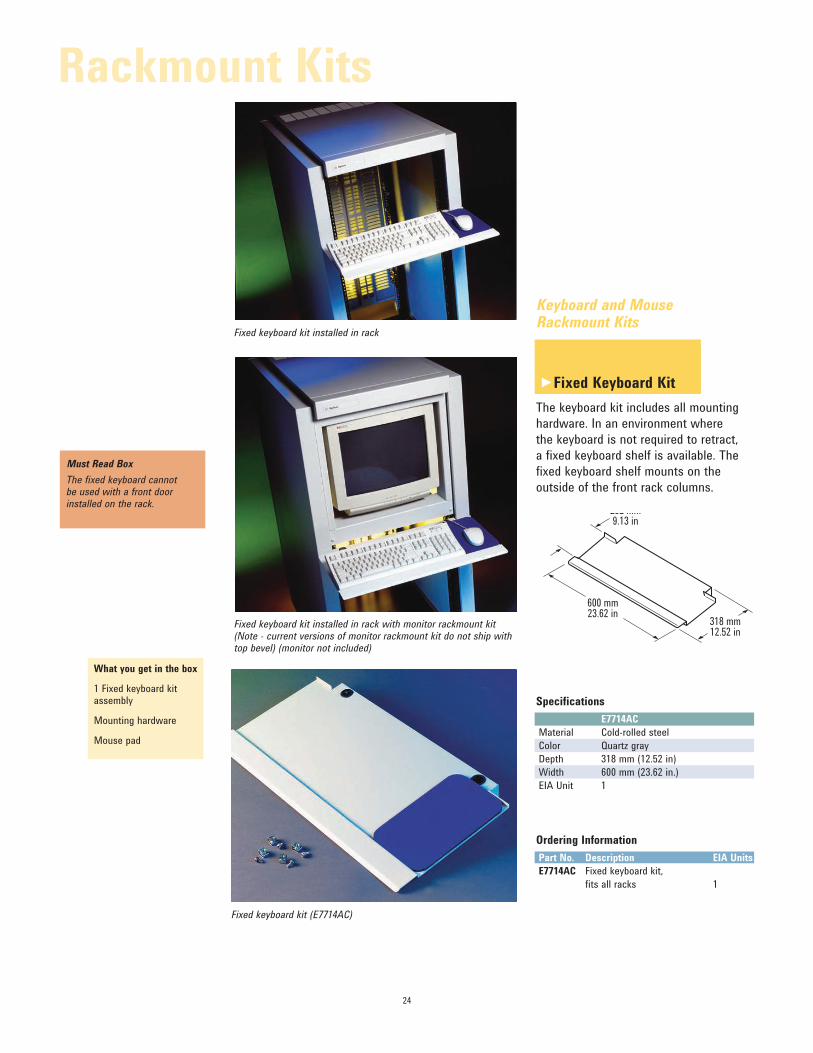
Retractable Keyboard Kit
Agilent’s compact shelving kit provides
a convenient enclosed keyboard system
that requires minimum rack space, saving
valuable space for your instruments.
The kit can accommodate any standard
keyboard and mouse. The retractable
keyboard shelf slides into the rack when
not in use. When retracted, the shelf
does not extend from the rack. Keyboard
security is available by using a front door
on the rack cabinet. The keyboard kit
includes all mounting hardware.
Keyboard and Mouse Rackmount Kits
Select a fixed or retractable keyboard and mouse kit appropriate for your needs.
Keyboard and mouse are not included. Consider purchasing the steel ballast
(C2790AC) to use with your keyboard and mouse kit. The ballast provides anti-tip
capability when the shelf is extended.Keyboard and Mouse Rackmount Kits
Specifications
J1518AC
Material Cold-rolled steel
Weight 12.9 kg (28.5 lbs)
Color Quartz gray
Depth 685 mm (26.97 in.)
Width 480 mm (18.9 in.)
Load Capacity 22.7 kg (50 lbs)
EIA Unit 2
Ordering Information
Part No. Description EIA Units
J1518AC Retractable keyboard kit,
fits all racks 2
480 mm18.9 in
191.6 mm7.54 in
208.7 mm8.22 in
685 mm26.97 in
What you get in the box
1 keyboard kit assembly
2 Rear brackets
Mounting hardware
Mouse pad
Retractable keyboard kit, retracted in rack
Retractable keyboard kit installed in rack
Retractable keyboard kit (J1518AC)
Rackmount Kits
►
24
Keyboard and Mouse Rackmount Kits
Fixed Keyboard Kit
The keyboard kit includes all mounting
hardware. In an environment where
the keyboard is not required to retract,
a fixed keyboard shelf is available. The
fixed keyboard shelf mounts on the
outside of the front rack columns.
Specifications
E7714AC
Material Cold-rolled steel
Color Quartz gray
Depth 318 mm (12.52 in)
Width 600 mm (23.62 in.)
EIA Unit 1
Ordering Information
Part No. Description EIA Units
E7714AC Fixed keyboard kit,
fits all racks 1
What you get in the box
1 Fixed keyboard kit assembly
Mounting hardware
Mouse pad
Must Read Box
The fixed keyboard cannot be used with a front door installed on the rack.
600 mm23.62 in
318 mm12.52 in
232 mm9.13 in
Fixed keyboard kit installed in rack
Fixed keyboard kit installed in rack with monitor rackmount kit (Note - current versions of monitor rackmount kit do not ship with top bevel) (monitor not included)
Fixed keyboard kit (E7714AC)
Rackmount Kits
►
88.1 mm (3.5 in) H
132.6 mm (5.25 in) H
177.0 mm (7 in) H
221.5 mm (8.75 in) H
265.9 mm (10.5 in) H
310.4 mm (12.25 in) H
7 EIA
6 EIA
5 EIA
4 EIA
3 EIA
2 EIA
HEIGHT
Full Module
1 MW
HalfModule
HalfModule
269.2 mm(11 in) D
345.4 mm (14 in) D
421.6 mm (17 in) D
497.8 mm (20 in) D
574.0 mm (23 in) D
QuarterModule
QuarterModule
QuarterModule
QuarterModule
1/2 MW 1/2 MW
3/4 MW1/4MW
WIDTH DEPTH
25
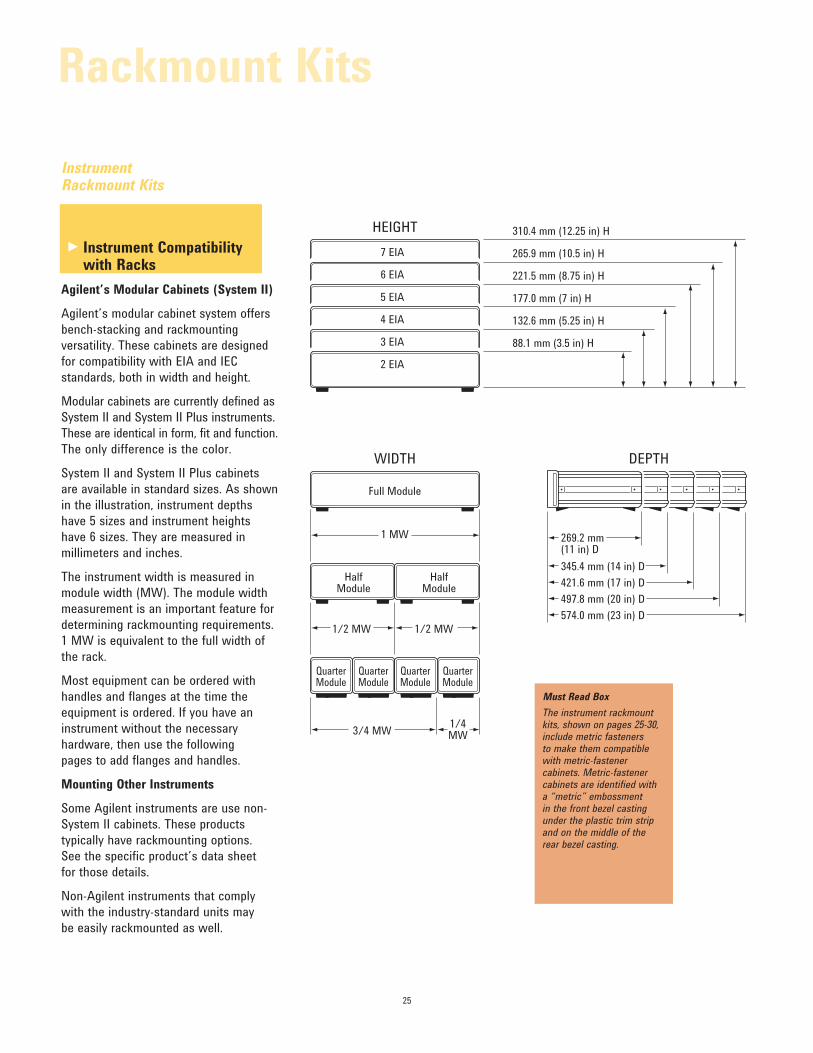
Instrument Compatibility with Racks
Agilent’s Modular Cabinets (System II)
Agilent’s modular cabinet system offers
bench-stacking and rackmounting
versatility. These cabinets are designed
for compatibility with EIA and IEC
standards, both in width and height.
Modular cabinets are currently defined as
System II and System II Plus instruments.
These are identical in form, fit and function.
The only difference is the color.
System II and System II Plus cabinets
are available in standard sizes. As shown
in the illustration, instrument depths
have 5 sizes and instrument heights
have 6 sizes. They are measured in
millimeters and inches.
The instrument width is measured in
module width (MW). The module width
measurement is an important feature for
determining rackmounting requirements.
1 MW is equivalent to the full width of
the rack.
Most equipment can be ordered with
handles and flanges at the time the
equipment is ordered. If you have an
instrument without the necessary
hardware, then use the following
pages to add flanges and handles.
Mounting Other Instruments
Some Agilent instruments are use non-
System II cabinets. These products
typically have rackmounting options.
See the specific product’s data sheet
for those details.
Non-Agilent instruments that comply
with the industry-standard units may
be easily rackmounted as well.
Must Read Box
The instrument rackmount kits, shown on pages 25-30, include metric fasteners to make them compatible with metric-fastener cabinets. Metric-fastener cabinets are identified with a “metric” embossment in the front bezel casting under the plastic trim strip and on the middle of the rear bezel casting.
Instrument Rackmount Kits
Rackmount Kits
►
26
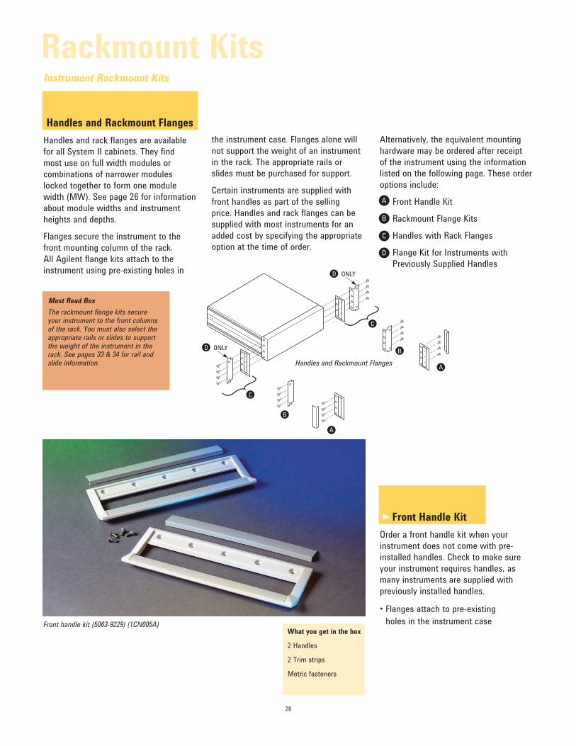
Handles and Rackmount Flanges
Handles and rack flanges are available
for all System II cabinets. They find
most use on full width modules or
combinations of narrower modules
locked together to form one module
width (MW). See page 26 for information
about module widths and instrument
heights and depths.
Flanges secure the instrument to the
front mounting column of the rack.
All Agilent flange kits attach to the
instrument using pre-existing holes in
the instrument case. Flanges alone will
not support the weight of an instrument
in the rack. The appropriate rails or
slides must be purchased for support.
Certain instruments are supplied with
front handles as part of the selling
price. Handles and rack flanges can be
supplied with most instruments for an
added cost by specifying the appropriate
option at the time of order.
Must Read Box
The rackmount flange kits secure your instrument to the front columns of the rack. You must also select the appropriate rails or slides to support the weight of the instrument in the rack. See pages 33 & 34 for rail and slide information.
What you get in the box
2 Handles
2 Trim strips
Metric fasteners
Front Handle Kit
Order a front handle kit when your
instrument does not come with pre-
installed handles. Check to make sure
your instrument requires handles, as
many instruments are supplied with
previously installed handles.
• Flanges attach to pre-existing holes in the instrument case
Alternatively, the equivalent mounting
hardware may be ordered after receipt
of the instrument using the information
listed on the following page. These order
options include:
Front Handle Kit
Rackmount Flange Kits
Handles with Rack Flanges
Flange Kit for Instruments with
Previously Supplied Handles
A
B
C
D
A
A
B
B
C
D ONLY
D ONLY
C
Handles and Rackmount Flanges
Front handle kit (5063-9229) (1CN005A)
Instrument Rackmount Kits
Rackmount Kits
►
27
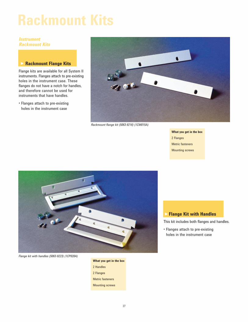
What you get in the box
2 Flanges
Metric fasteners
Mounting screws
Instrument Rackmount Kits
Rackmount Flange Kits
Flange kits are available for all System II
instruments. Flanges attach to pre-existing
holes in the instrument case. These
flanges do not have a notch for handles,
and therefore cannot be used for
instruments that have handles.
• Flanges attach to pre-existing holes in the instrument case
What you get in the box
2 Handles
2 Flanges
Metric fasteners
Mounting screws
Flange Kit with Handles
This kit includes both flanges and handles.
• Flanges attach to pre-existing holes in the instrument case
Rackmount flange kit (5063-9216) (1CM015A)
Flange kit with handles (5063-9223) (1CP020A)
Rackmount Kits
►
►
28
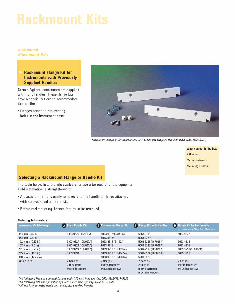
Instrument Rackmount Kits
Rackmount Flange Kit for Instruments with Previously Supplied Handles
Certain Agilent instruments are supplied
with front handles. These flange kits
have a special cut out to accommodate
the handles.
• Flanges attach to pre-existing holes in the instrument case
What you get in the box
2 Flanges
Metric fasteners
Mounting screws
Selecting a Rackmount Flange or Handle Kit
The table below lists the kits available for use after receipt of the equipment.
Field installation is straightforward.
• A plastic trim strip is easily removed and the handle or flange attaches with screws supplied in the kit.
• Before rackmounting, bottom feet must be removed.
Ordering Information
Instrument Module Height Front Handle Kit Rackmount Flange Kit3 Flange Kit with Handles Flange Kit for Instruments
w/Previously Supplied Handles
88.1 mm (3.5 in) 5063-9226 (1CN006A) 5063-92121 (34191A) 5063-92191 5063-92321
88.1 mm (3.5 in) — 5063-92132 5063-92202 —132.6 mm (5.25 in) 5063-9227 (1CN007A) 5063-9214 (34192A) 5063-9221 (1CP008A) 5063-9234
177.0 mm (7.0 in) 5063-9228 (1CN003A) 5063-9215 5063-9222 (1CP005A) 5063-9235
221.5 mm (8.75 in) 5063-9229 (1CN005A) 5063-9216 (1CM015A) 5063-9223 (1CP020A) 5063-9236 (1CM043A)
265.9 mm (10.5 in) 5063-9230 5063-9217 (1CM042A) 5063-9224 (1CP019A) 5063-9237
310.4 mm (12.25 in) — 5063-9218 (1CM033A) 5063-9225 —Kit includes 2 handles 2 flanges 2 handles 2 flanges
2 trim strips metric fasteners 2 flanges metric fasteners
metric fasteners mounting screws metric fasteners mounting screws
mounting screws
A B C D
Rackmount flange kit for instruments with previously supplied handles (5063-9236) (1CM043A)
1The following kits use standard flanges with 1.75 inch hole spacing: 5063-9212/9219/92322The following kits use special flange with 3 inch hole spacing: 5063-9213/92203Will not fit onto instruments with previously supplied handles
Rackmount Kits
►
29
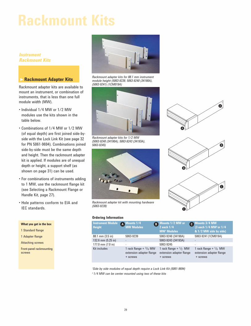
1Side by side modules of equal depth require a Lock Link Kit (5061-9694)
2 1/4 MW can be center mounted using two of these kits
What you get in the box
1 Standard flange
1 Adapter flange
Attaching screws
Front-panel rackmounting screws
Ordering Information
Instrument Module Mounts 1/4 Mounts 1/2 MW or Mounts 3/4 MW
Height MW Modules 2 each 1/4 (3 each 1/4 MW2 or 1/4
MW1 Modules & 1/2 MW side by side)
88.1 mm (3.5 in) 5063-9239 5063-9240 (34190A) 5063-9241 (1CM019A)
132.6 mm (5.25 in) - 5063-9243 (34193A) -
177.0 mm (7.0 in) - 5063-9245 -
Kit includes 1 rack flange + 3/4 MW 1 rack flange + 1/2 MW 1 rack flange + 1/4 MW
extension adapter flange extension adapter flange extension adapter flange
+ screws + screws + screws
A B C
Rackmount Adapter Kits
Rackmount adapter kits are available to
mount an instrument, or combination of
instruments, that is less than one full
module width (MW).
• Individual 1/4 MW or 1/2 MW modules use the kits shown in the
table below.
• Combinations of 1/4 MW or 1/2 MW (of equal depth) are first joined side-by-
side with the Lock Link Kit (see page 32
for PN 5061-9694). Combinations joined
side-by-side must be the same depth
and height. Then the rackmount adapter
kit is applied. If modules are of unequal
depth or height, a support shelf (as
shown on page 31) can be used.
• For combinations of instruments adding to 1 MW, use the rackmount flange kit
(see Selecting a Rackmount Flange or
Handle Kit, page 27).
• Hole patterns conform to EIA and IEC standards.
Rackmount adapter kit with mounting hardware (5063-9239)
Rackmount adapter kits for 88.1 mm instrument module height (5063-9239, 5063-9240 (34190A), (5063-9241) (1CM019A)
Rackmount adapter kits for 1/2 MW (5063-9240 (34190A), 5063-9243 (34193A), 5063-9245)
Instrument Rackmount Kits
Rackmount Kits
A
A
B
BA
C
C
►
30
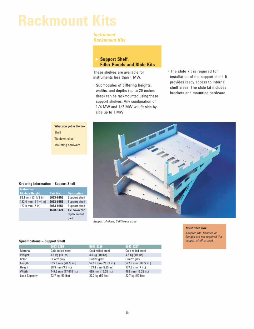
Support Shelf, Filler Panels and Slide Kits
These shelves are available for
instruments less than 1 MW.
• Submodules of differing heights, widths, and depths (up to 20 inches
deep) can be rackmounted using these
support shelves. Any combination of
1/4 MW and 1/2 MW will fit side-by-
side up to 1 MW.
Specifications – Support Shelf
5063-9255 5063-9256 5063-9257
Material Cold-rolled steel Cold-rolled steel Cold-rolled steel
Weight 4.5 kg (10 lbs) 4.5 kg (10 lbs) 4.5 kg (10 lbs)
Color Quartz gray Quartz gray Quartz gray
Length 527.6 mm (20.77 in.) 527.6 mm (20.77 in.) 527.6 mm (20.77 in.)
Height 88.9 mm (3.5 in.) 133.4 mm (5.25 in.) 177.8 mm (7 in.)
Width 447.5 mm (17.618 in.) 489 mm (19.25 in.) 489 mm (19.25 in.)
Load Capacity 22.7 kg (50 lbs) 22.7 kg (50 lbs) 22.7 kg (50 lbs)
Ordering Information – Support Shelf
Instrument
Module Height Part No. Description
88.1 mm (3 1/2 in) 5063-9255 Support shelf
132.6 mm (5 1/4 in) 5063-9256 Support shelf
177.0 mm (7 in) 5063-9257 Support shelf
1600-1424 Tie down clip
replacement
part
• The slide kit is required for installation of the support shelf. It
provides ready access to internal
shelf areas. The slide kit includes
brackets and mounting hardware.
What you get in the box
Shelf
Tie down clips
Mounting hardware
Must Read Box
Adapter kits, handles or flanges are not required if a support shelf is used.
Support shelves, 3 different sizes
Instrument Rackmount Kits
Rackmount Kits
►
31
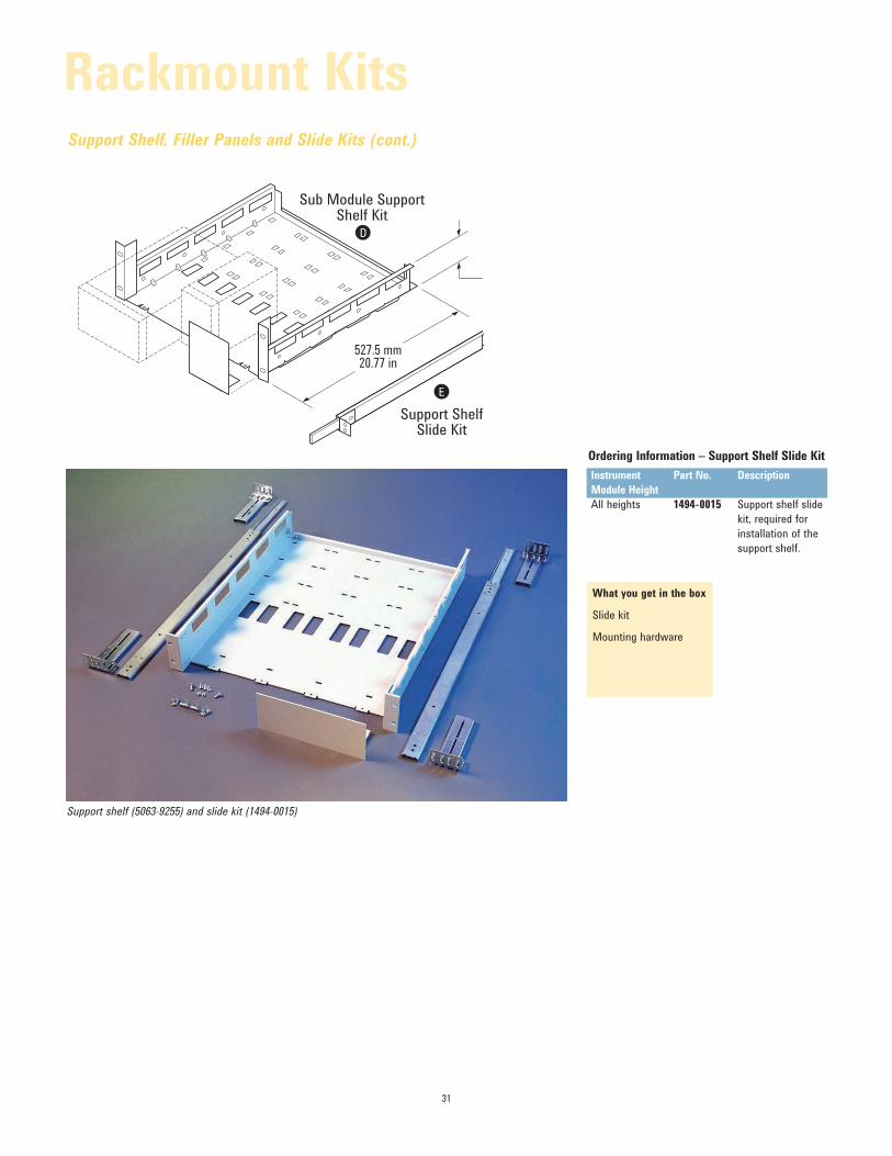
What you get in the box
Slide kit
Mounting hardware
Ordering Information – Support Shelf Slide Kit
Instrument Part No. Description
Module Height
All heights 1494-0015 Support shelf slide
kit, required for
installation of the
support shelf.
Support Shelf, Filler Panels and Slide Kits (cont.)
D
E
Support ShelfSlide Kit
Sub Module SupportShelf Kit
527.5 mm20.77 in
Support shelf (5063-9255) and slide kit (1494-0015)
Rackmount Kits
32
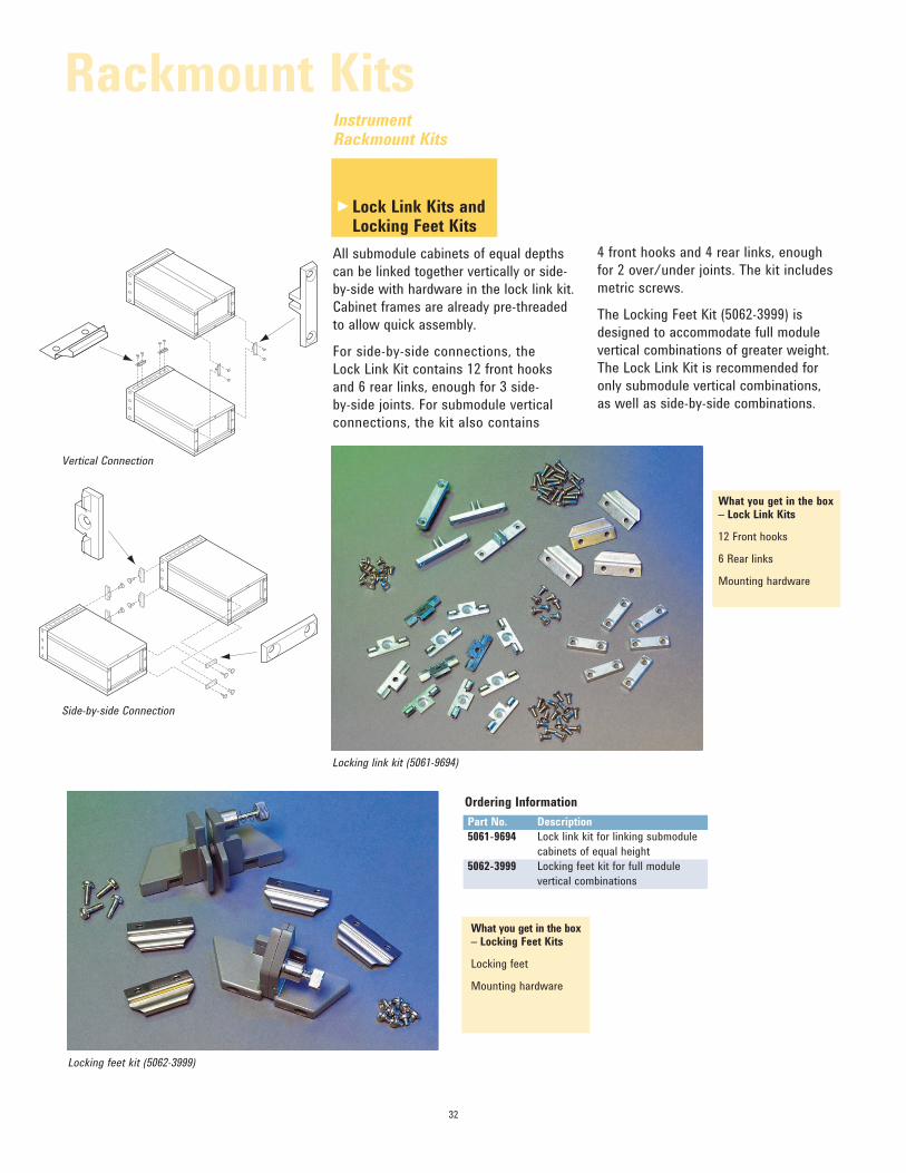
What you get in the box – Lock Link Kits
12 Front hooks
6 Rear links
Mounting hardware
Lock Link Kits and Locking Feet Kits
All submodule cabinets of equal depths
can be linked together vertically or side-
by-side with hardware in the lock link kit.
Cabinet frames are already pre-threaded
to allow quick assembly.
For side-by-side connections, the
Lock Link Kit contains 12 front hooks
and 6 rear links, enough for 3 side-
by-side joints. For submodule vertical
connections, the kit also contains
What you get in the box – Locking Feet Kits
Locking feet
Mounting hardware
Ordering Information
Part No. Description
5061-9694 Lock link kit for linking submodule
cabinets of equal height
5062-3999 Locking feet kit for full module
vertical combinations
4 front hooks and 4 rear links, enough
for 2 over/under joints. The kit includes
metric screws.
The Locking Feet Kit (5062-3999) is
designed to accommodate full module
vertical combinations of greater weight.
The Lock Link Kit is recommended for
only submodule vertical combinations,
as well as side-by-side combinations.
Locking feet kit (5062-3999)
Instrument Rackmount Kits
Rackmount Kits
►
Vertical Connection
Side-by-side Connection
Locking link kit (5061-9694)
33
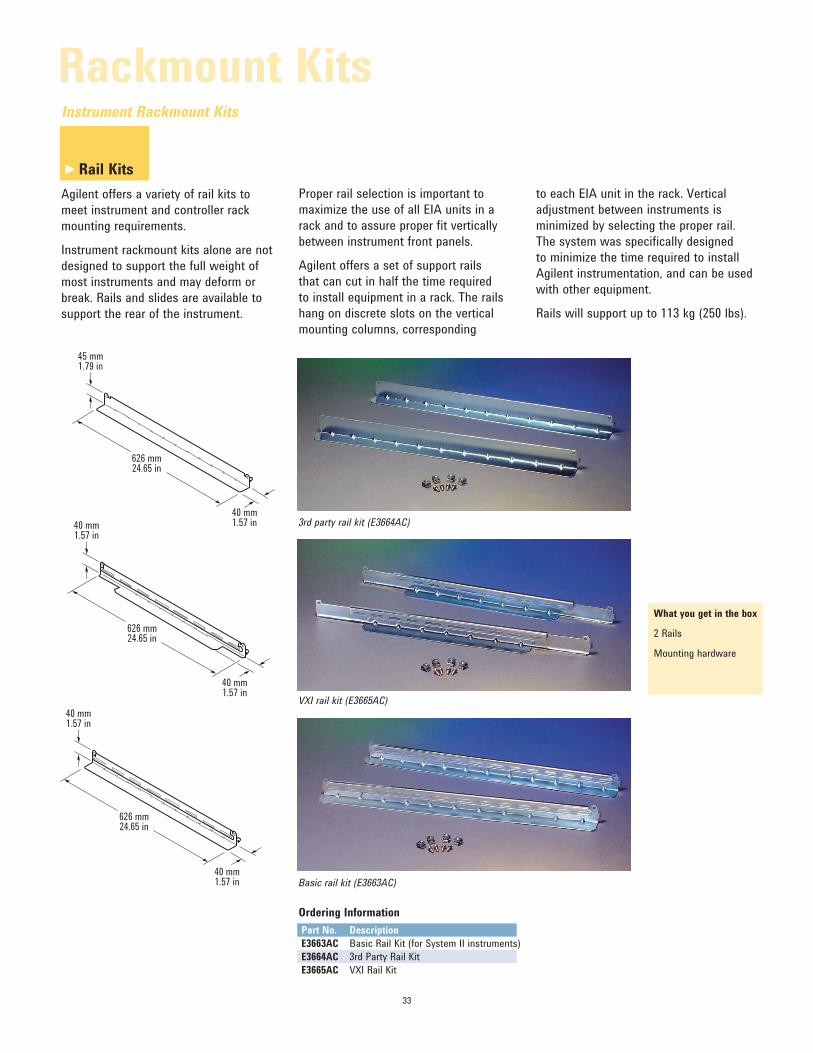
Rail Kits
Agilent offers a variety of rail kits to
meet instrument and controller rack
mounting requirements.
Instrument rackmount kits alone are not
designed to support the full weight of
most instruments and may deform or
break. Rails and slides are available to
support the rear of the instrument.
Ordering Information
Part No. Description
E3663AC Basic Rail Kit (for System II instruments)
E3664AC 3rd Party Rail Kit
E3665AC VXI Rail Kit
What you get in the box
2 Rails
Mounting hardware
40 mm1.57 in
40 mm1.57 in
626 mm24.65 in
45 mm1.79 in
40 mm1.57 in
626 mm24.65 in
40 mm1.57 in
40 mm1.57 in
626 mm24.65 in
Proper rail selection is important to
maximize the use of all EIA units in a
rack and to assure proper fit vertically
between instrument front panels.
Agilent offers a set of support rails
that can cut in half the time required
to install equipment in a rack. The rails
hang on discrete slots on the vertical
mounting columns, corresponding
to each EIA unit in the rack. Vertical adjustment between instruments is
minimized by selecting the proper rail.
The system was specifically designed
to minimize the time required to install
Agilent instrumentation, and can be used
with other equipment.
Rails will support up to 113 kg (250 lbs).
3rd party rail kit (E3664AC)
VXI rail kit (E3665AC)
Basic rail kit (E3663AC)
Instrument Rackmount Kits
Rackmount Kits
►
34
Ordering Information
Part No. Description
1494-0061 End brackets, standard duty
1494-0064 End brackets, heavy duty
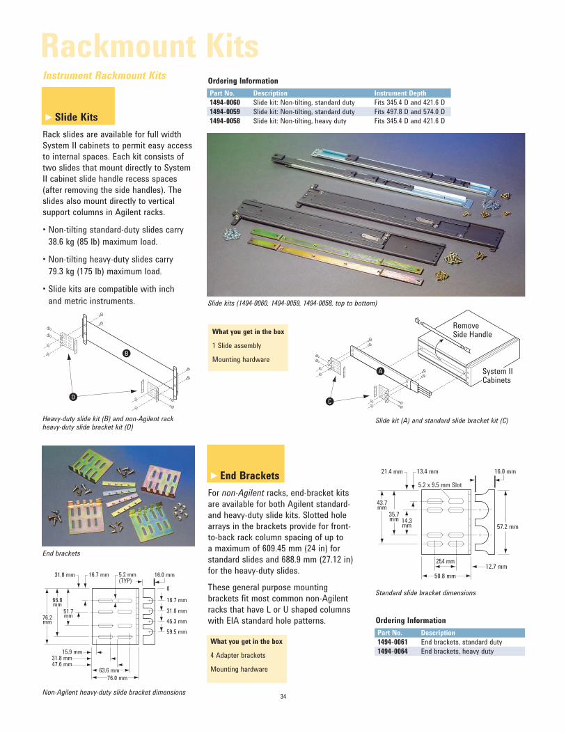
Slide Kits
Rack slides are available for full width
System II cabinets to permit easy access
to internal spaces. Each kit consists of
two slides that mount directly to System
II cabinet slide handle recess spaces
(after removing the side handles). The
slides also mount directly to vertical
support columns in Agilent racks.
• Non-tilting standard-duty slides carry 38.6 kg (85 lb) maximum load.
• Non-tilting heavy-duty slides carry 79.3 kg (175 lb) maximum load.
• Slide kits are compatible with inch and metric instruments.
Ordering Information
Part No. Description Instrument Depth
1494-0060 Slide kit: Non-tilting, standard duty Fits 345.4 D and 421.6 D
1494-0059 Slide kit: Non-tilting, standard duty Fits 497.8 D and 574.0 D
1494-0058 Slide kit: Non-tilting, heavy duty Fits 345.4 D and 421.6 D
End Brackets
For non-Agilent racks, end-bracket kits
are available for both Agilent standard-
and heavy-duty slide kits. Slotted hole
arrays in the brackets provide for front-
to-back rack column spacing of up to
a maximum of 609.45 mm (24 in) for
standard slides and 688.9 mm (27.12 in)
for the heavy-duty slides.
These general purpose mounting
brackets fit most common non-Agilent
racks that have L or U shaped columns
with EIA standard hole patterns.
What you get in the box
1 Slide assembly
Mounting hardware
What you get in the box
4 Adapter brackets
Mounting hardware
B
D
Heavy-duty slide kit (B) and non-Agilent rack heavy-duty slide bracket kit (D)
76.0 mm
15.9 mm
76.2mm
63.6 mm
16.0 mm
16.7 mm
0
31.0 mm
45.3 mm
59.5 mm
31.8 mm 16.7 mm
51.7mm
66.8mm
5.2 mm(TYP)
31.8 mm47.6 mm
Non-Agilent heavy-duty slide bracket dimensions
16.0 mm21.4 mm 13.4 mm
35.7mm 14.3
mm
43.7mm
5.2 x 9.5 mm Slot
12.7 mm25.4 mm
50.8 mm
57.2 mm
Standard slide bracket dimensions
RemoveSide Handle
System IICabinets
A
C
Slide kit (A) and standard slide bracket kit (C)
End brackets
Slide kits (1494-0060, 1494-0059, 1494-0058, top to bottom)
Instrument Rackmount Kits
Rackmount Kits
►
►
35
What you get in the box
1 feedthrough panel
Mounting hardware
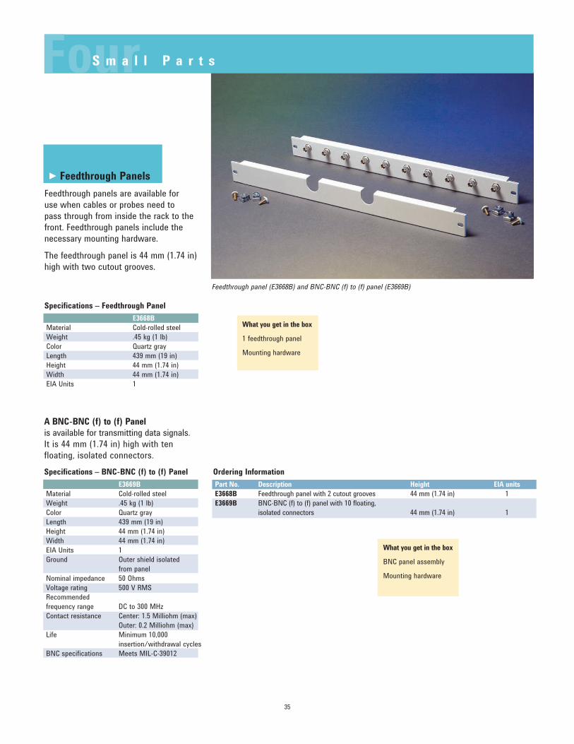
Feedthrough Panels
Feedthrough panels are available for
use when cables or probes need to
pass through from inside the rack to the
front. Feedthrough panels include the
necessary mounting hardware.
The feedthrough panel is 44 mm (1.74 in)
high with two cutout grooves.
Specifications – Feedthrough Panel
E3668B
Material Cold-rolled steel
Weight .45 kg (1 lb)
Color Quartz gray
Length 439 mm (19 in)
Height 44 mm (1.74 in)
Width 44 mm (1.74 in)
EIA Units 1
Specifications – BNC-BNC (f) to (f) Panel
E3669B
Material Cold-rolled steel
Weight .45 kg (1 lb)
Color Quartz gray
Length 439 mm (19 in)
Height 44 mm (1.74 in)
Width 44 mm (1.74 in)
EIA Units 1
Ground Outer shield isolated
from panel
Nominal impedance 50 Ohms
Voltage rating 500 V RMSRecommended
frequency range DC to 300 MHz
Contact resistance Center: 1.5 Milliohm (max)
Outer: 0.2 Milliohm (max)
Life Minimum 10,000
insertion/withdrawal cycles
BNC specifications Meets MIL-C-39012
A BNC-BNC (f) to (f) Panel
is available for transmitting data signals.
It is 44 mm (1.74 in) high with ten
floating, isolated connectors.
What you get in the box
BNC panel assembly
Mounting hardware
Ordering Information
Part No. Description Height EIA units
E3668B Feedthrough panel with 2 cutout grooves 44 mm (1.74 in) 1
E3669B BNC-BNC (f) to (f) panel with 10 floating,
isolated connectors 44 mm (1.74 in) 1
Feedthrough panel (E3668B) and BNC-BNC (f) to (f) panel (E3669B)
FourS m a l l P a r t s
►
36
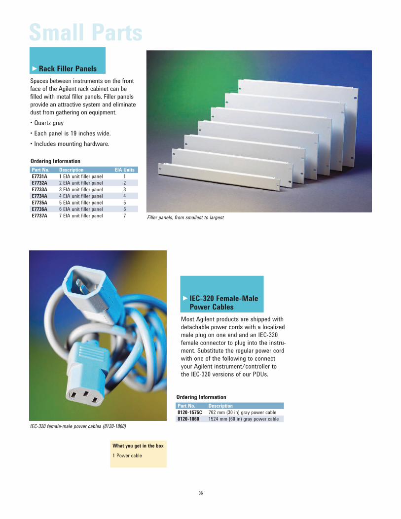
Rack Filler Panels
Spaces between instruments on the front
face of the Agilent rack cabinet can be
filled with metal filler panels. Filler panels
provide an attractive system and eliminate
dust from gathering on equipment.
• Quartz gray• Each panel is 19 inches wide.• Includes mounting hardware.
Ordering Information
Part No. Description EIA Units
E7731A 1 EIA unit filler panel 1
E7732A 2 EIA unit filler panel 2
E7733A 3 EIA unit filler panel 3
E7734A 4 EIA unit filler panel 4
E7735A 5 EIA unit filler panel 5
E7736A 6 EIA unit filler panel 6
E7737A 7 EIA unit filler panel 7
What you get in the box
1 Power cable
IEC-320 Female-Male Power Cables
Most Agilent products are shipped with
detachable power cords with a localized
male plug on one end and an IEC-320
female connector to plug into the instru-
ment. Substitute the regular power cord
with one of the following to connect
your Agilent instrument/controller to
the IEC-320 versions of our PDUs.
Ordering Information
Part No. Description
8120-1575C 762 mm (30 in) gray power cable
8120-1860 1524 mm (60 in) gray power cable
Filler panels, from smallest to largest
IEC-320 female-male power cables (8120-1860)
Small Parts
►
►
37
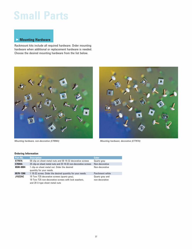
Mounting Hardware
Rackmount kits include all required hardware. Order mounting
hardware when additional or replacement hardware is needed.
Choose the desired mounting hardware from the list below.
Ordering Information
Part No. Description Color
E7797A 50 clip-on sheet metal nuts and 50 10-32 decorative screws Quartz gray
E7694A 25 clip-on sheet metal nuts and 25 10-32 non-decorative screws Non-decorative
0590-0804 1 clip-on sheet metal nut. Order the desired Non-decorative
quantity for your needs.
0570-1366 1 10-32 screw. Order the desired quantity for your needs. Parchment white
J1522AC 10 Torx T25 decorative screws (quartz gray), Quartz gray and
10 Torx T25 non-decorative screws with lock washers, non-decorative
and 20 U-type sheet metal nuts
Mounting hardware, non-decorative (E7694A) Mounting hardware, decorative (E7797A)
Small Parts
►
Small Parts
Caster
Heavy duty 3-inch casters are shipped
with all standard Agilent racks.
Agilent’s casters may also be ordered
if a replacement or extra set of casters
is needed.
What you get in the box
1 Caster
Ordering Information
Part No. Description
1492-0159C Casters for standard racks
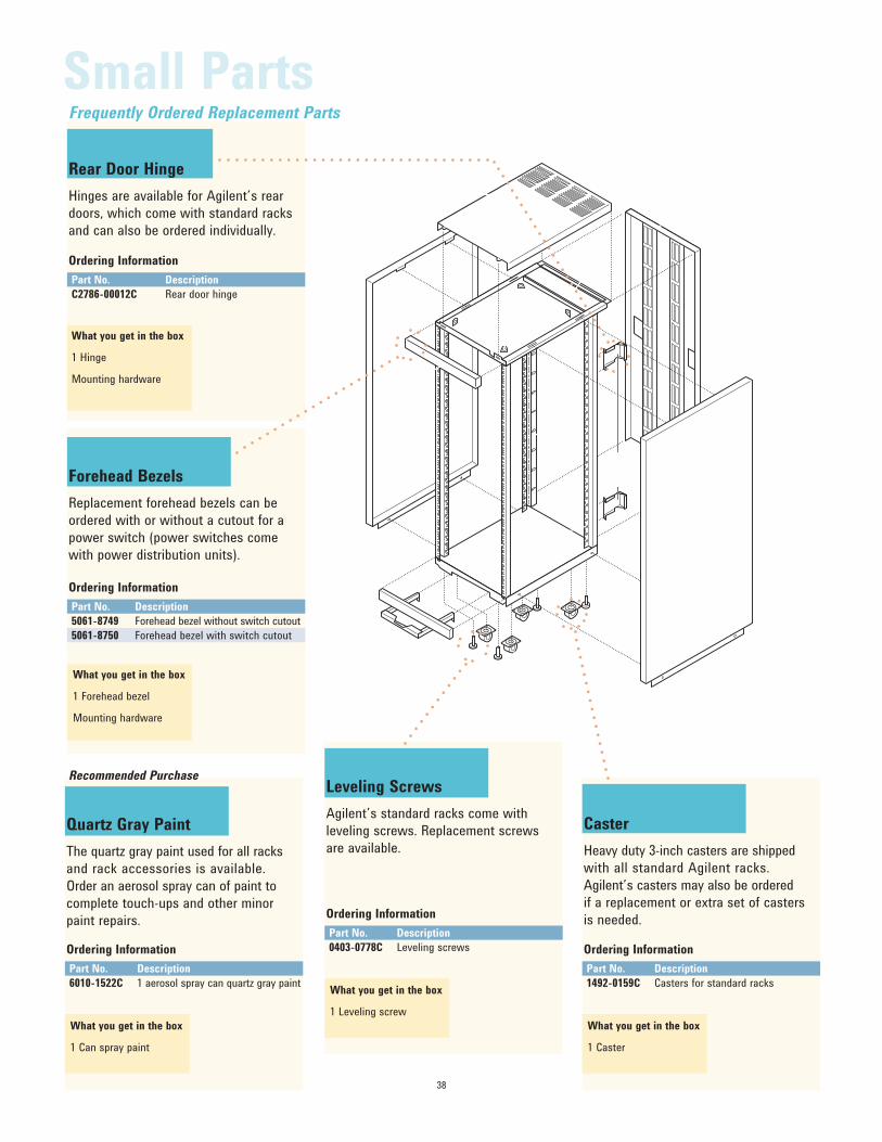
Rear Door Hinge
Hinges are available for Agilent’s rear
doors, which come with standard racks
and can also be ordered individually.
What you get in the box
1 Hinge
Mounting hardware
Ordering Information
Part No. Description
C2786-00012C Rear door hinge
Forehead Bezels
Replacement forehead bezels can be
ordered with or without a cutout for a
power switch (power switches come
with power distribution units).
Ordering Information
Part No. Description
5061-8749 Forehead bezel without switch cutout
5061-8750 Forehead bezel with switch cutout
What you get in the box
1 Forehead bezel
Mounting hardware
Quartz Gray Paint
The quartz gray paint used for all racks
and rack accessories is available.
Order an aerosol spray can of paint to
complete touch-ups and other minor
paint repairs.
Ordering Information
Part No. Description
6010-1522C 1 aerosol spray can quartz gray paint
What you get in the box
1 Can spray paint
Leveling Screws
Agilent’s standard racks come with
leveling screws. Replacement screws
are available.
Ordering Information
Part No. Description
0403-0778C Leveling screws
What you get in the box
1 Leveling screw
Recommended Purchase
Frequently Ordered Replacement Parts
38

39
Agilent Testmobile Carts add protection
and mobility to test instruments and
systems. The convenience of mobility
makes instruments readily available
when needed. The cart effectively
extends the amount of lab bench space.
Ergonomic cart and accessory design
makes test equipment accessible to the
operator, whether seated or standing
at the test area. Additionally, several
operators can cost effectively share
expensive equipment that has been
mounted on a Testmobile Cart.
Competitively priced Agilent testmobile
carts are offered in cart capacities
to provide optimum instrument test
configuration:
• Scope cart, 59 kg (130 lb)
• System cart, 227 kg (500 lb).
A variety of easy-to-mount accessories
are available for customized solutions.
Add Mobility to Your Instruments
Agilent Testmobile carts provide
convenient mobility of test equipment,
PCs, or workstations to make them
readily available when needed. This
capability effectively extends the amount
of lab bench space available. Mar-
resistant, heavy-duty 5-inch hard rubber
casters make moving instruments easy.
All casters swivel, which lets the cart
move right up to the workbench.
Bring the Equipment to the Test
Rather than bringing the test to the
equipment, Agilent Testmobile carts
bring the equipment to the test, to
save time and get right to the task.
Testmobile carts provide a convenient
way to move everything from a small
oscilloscope to a complete test system
to the work to be tested.
Share Expensive Instruments
Agilent Testmobile carts allow several
operators in a work group to cost-
effectively share expensive equipment.
In the case of a small test system,
all instruments can be conveniently
combined in one place through the
sufficient space, load capacity, and
rackmount capability of the testmobile
system cart.
Protect Your Investment
Unlike general-purpose cart design,
Agilent testmobile carts have a nylon
strap and steel buckle that secure
instruments to the cart, and instrument
feet fit securely in slots in both upper
tilt tray and lower fixed tray. Expensive
instruments are prevented from sliding
or tipping off the cart. Locking brakes
on rear wheels provide added safety
and convenience.
Use Instruments with Ease
The ergonomically designed tilt tray
adjusts 30-plus degrees for viewing
and using instruments in comfort
whether seated or standing. Lifting
and carrying heavy instruments is no
longer necessary with the mobility
provided by Agilent testmobile carts.
FiveT e s t m o b i l e s a n d A c c e s s o r i e s
40
Key Features
Agilent’s Testmobile Carts offer the
following attractive features:
• Ergonomic design. Test equipment is operator-accessible whether seated
or standing.
• Heavy-duty casters make moving instruments easy.
• Includes a nylon strap and steel buckles to secure instruments to
the cart.
• Tilt tray adjusts 30-plus degrees for viewing comfort.
Enhance Instrument Output
Agilent Testmobile system and instrument
carts can be customized with a range of
easy-to-mount accessories that enhance
instrument input and output:
• Work surface and antistatic mat that provide a secure, static free work area
in front of the instrument
• Plotter/printer stand, which can be set up either 305 mm or 381 mm (12 in or
15 in) high, enables hardcopy output
on the spot
• Storage drawer (3.5 inch or 5.25 inch) for a convenient place to store probes,
cables, and manuals
• Angle rails for supporting rack mounted instruments
• Attractive quartz gray color
Testmobile Cart Selection Criteria
A key criterion for cart selection is
instrument depth. For instruments with a
depth up to 17 inches, select the Agilent
1180CZ testmobile scope cart. The Agilent
1181BZ testmobile system cart should
be used for instruments up to 24 inches.
Static drag chain is supplied on the
1181BZ.
What you get in the box
Scope cart assembly with tray
Tubular handle
4 Casters
Mounting hardware
Torx T25 screwdriver
Nylon strap with steel buckle
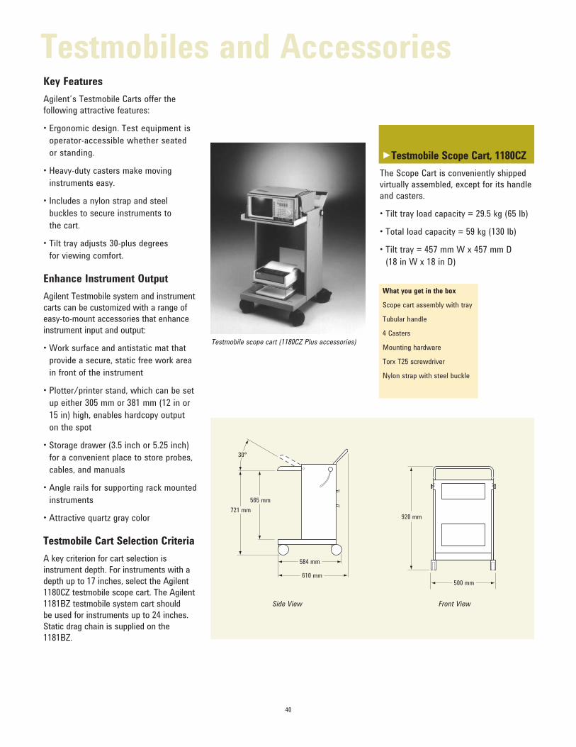
Testmobile Scope Cart, 1180CZ
The Scope Cart is conveniently shipped
virtually assembled, except for its handle
and casters.
• Tilt tray load capacity = 29.5 kg (65 lb)
• Total load capacity = 59 kg (130 lb)
• Tilt tray = 457 mm W x 457 mm D (18 in W x 18 in D)
Testmobile scope cart (1180CZ Plus accessories)
30°
565 mm
584 mm
610 mm
721 mm
500 mm
920 mm
Side View Front View
Testmobiles and Accessories
►

41
Testmobile System Cart, 1181BZ
The System Cart is a small mobile rack
that allows for additional equipment to
be installed. That cart has space for the
rackmounting of any 19” EIA instrument
up to 24” deep. The cart is conveniently
shipped virtually assembled, except for
its handle.
• Tilt tray load capacity = 90.7 kg (200 lb)
• Total load capacity = 226.8 kg (500 lb)
What you get in the box
System cart assembly with tray and casters
Tubular handle
One set of support rails
Mounting hardware
Torx T25 screwdriver
Nylon strap with steel buckle
Testmobile system cart (1181BZ Plus accessories)
30°
830 mm
838 mm
721 mm
585 mm
920 mm
367 mm*
535 mm
Side View Front View
Ordering Information
Prod. No. Description
1180CZ Scope cart
1181BZ System cart
Specifications
1180CZ Scope Cart 1181BZ System Cart
Capabilities
Tilt tray load 29.5 kg (65 lb) 90.7 kg (200 lb)
Total load 59.0 kg (130 lb) 226.8 kg (500 lb)
Cart net weight 18.1 kg (40 lb) 39.0 kg (86 lb)
Dimensions
Tilt tray size (w x d) 457 x 457 mm (18 x 18 in) 559 x 660 mm (22 x 26 in)
Height 721 mm (28.4 in) 721 mm (28.4 in)
Width 475 mm (18.7 in) 566 mm (22.3 in)
Depth 508 mm (20.0 in) 737 mm (29.0 in)
Vertical rack space* n/a 533 mm (21.0 in – 12 EIA units)Maximum 432 mm (17.0 in) 635 mm (25.0 in)
Instrument Depth
Casters 101 mm (4 in) diameter 127 mm (5 in) diameter
* Vertical rack space is reduced the more the tilt tray is angled.
For all Testmobile Carts
• Tilt tray = 559 mm W x 660 mm D (22 in W x 26 in D)
• Rackmount any 19-inch EIA instrument up to 24 inches deep beneath the tilt
tray in EIA columns.
• 12 EIA units available for rackmounting.
• Includes one set of 5957-8476C angle rails to support rackmounted instruments.
Testmobiles and Accessories
►
42
Ordering Information
Part No. Description
35181HZ Testmobile printer/plotter stand
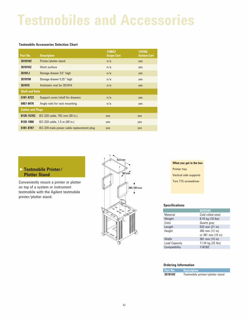
Specifications
35181HZ
Material Cold-rolled steel
Weight 8.16 kg (18 lbs)
Color Quartz gray
Length 533 mm (21 in)
Height 305 mm (12 in)
or 381 mm (15 in)
Width 381 mm (15 in)
Load Capacity 11.34 kg (25 lbs)
Compatibility 1181BZ
What you get in the box
Printer tray
Vertical side supports
Torx T15 screwdriver
Testmobile Printer/ Plotter Stand
Conveniently mount a printer or plotter
on top of a system or instrument
testmobile with the Agilent testmobile
printer/plotter stand.
Testmobile Accessories Selection Chart
Testmobiles and Accessories
►
Part No. Description
1180CZ
Scope Cart
1181BZ
System Cart
35181HZ Printer/plotter stand n/a yes
35181KZ Work surface n/a yes
35181J Storage drawer 3.5” high n/a yes
35181M Storage drawer 5.25” high n/a yes
35181E Antistatic mat for 35181K n/a yes
Shelf and Rails
5181-8723 Support cover/shelf for drawers n/a yes
5957-8476 Angle rails for rack mounting n/a yes
Cables and Plugs
8120-1575C IEC-320 cable, 762 mm (30 in.) yes yes
8120-1860 IEC-320 cable, 1.5 m (60 in.) yes yes
5181-8707 IEC-320 male power cable replacement plug yes yes

43
Testmobile Work Surface
Agilent’s testmobile work surface
provides additional work space on
a testmobile cart. It can be used for
accessories, writing, or a keyboard
and mouse. The work surface attaches
to the testmobile tilt tray.
Specifications
35181KZ
Material Cold-rolled steel
Weight 4.99 kg (11 lbs)
Color Quartz gray
Length 533 mm (21 in)
Width 305 mm (12 in)
Compatibility 1181BZ
457.2 mm
250.4 mm
What you get in the box
Work surface
Torx T15 screwdriver
Mounting hardware
Ordering Information
Part No. Description
35181KZ Work surface for 1181BZ
Testmobiles and Accessories
►
44
What you get in the box
Drawer with slides attached
Mounting hardware
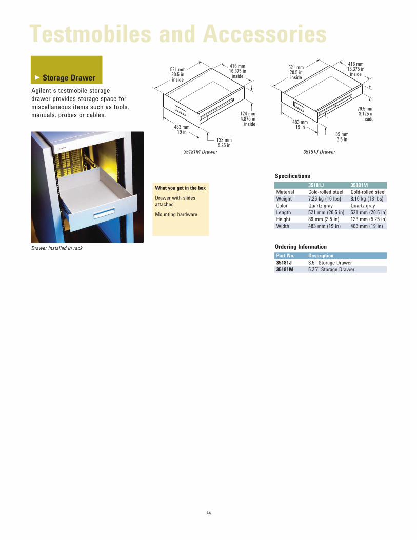
Storage Drawer
Agilent’s testmobile storage
drawer provides storage space for
miscellaneous items such as tools,
manuals, probes or cables.
Ordering Information
Part No. Description
35181J 3.5” Storage Drawer
35181M 5.25” Storage Drawer
Specifications
35181J 35181M
Material Cold-rolled steel Cold-rolled steel
Weight 7.26 kg (16 lbs) 8.16 kg (18 lbs)
Color Quartz gray Quartz gray
Length 521 mm (20.5 in) 521 mm (20.5 in)
Height 89 mm (3.5 in) 133 mm (5.25 in)
Width 483 mm (19 in) 483 mm (19 in)
35181C Drawer
521 mm20.5 ininside
416 mm16.375 in
inside
79.5 mm3.125 in
inside
89 mm3.5 in
483 mm19 in
521 mm20.5 ininside
416 mm16.375 in
inside
124 mm4.875 in
inside
133 mm5.25 in
483 mm19 in
35181M Drawer 35181J Drawer
Drawer installed in rack
Testmobiles and Accessories
►
45
What you get in the box
1 Power cable
Ordering Information
Part No. Description
8120-1575C 762 mm (30 in) gray female-male power cable
8120-1860 1524 mm (60 in) gray female-male power cable
5181-8707 IEC-320 male power cable replacement plug
IEC-320 Power Cables
Most Agilent products are shipped
with detachable power cords with a
localized male plug on one end and
an IEC-320 female connector to plug
into the instrument. Substitute the
regular power cord with 8120-1575C
or 8120-1860 to connect your Agilent
instrument/controller to the IEC-320
versions of our PDUs. We also offer
a male power cable conversion plug
(5181-8707).
Testmobiles and Accessories
www.lxistandard.org
LAN eXtensions for Instruments puts the power of Ethernet and the Web
inside your test systems. Agilent is a
founding member of the LXI consor-tium.
Agilent Channel Partners
www.agilent.com/find/channelpartners
Get the best of both worlds: Agilent’s
measurement expertise and product
breadth, combined with channel
partner convenience.
For more information on Agilent Technolo-gies’ products, applications or services, please contact your local Agilent office. The
complete list is available at:
www.agilent.com/find/contactus
Americas
Canada (877) 894 4414 Brazil (11) 4197 3600Mexico 01800 5064 800 United States (800) 829 4444
Asia Pacific
Australia 1 800 629 485China 800 810 0189Hong Kong 800 938 693India 1 800 112 929Japan 0120 (421) 345Korea 080 769 0800Malaysia 1 800 888 848Singapore 1 800 375 8100Taiwan 0800 047 866Other AP Countries (65) 375 8100
Europe & Middle East
Belgium 32 (0) 2 404 93 40 Denmark 45 45 80 12 15Finland 358 (0) 10 855 2100France 0825 010 700* *0.125 €/minute
Germany 49 (0) 7031 464 6333 Ireland 1890 924 204Israel 972-3-9288-504/544Italy 39 02 92 60 8484Netherlands 31 (0) 20 547 2111Spain 34 (91) 631 3300Sweden 0200-88 22 55United Kingdom 44 (0) 118 927 6201
For other unlisted countries: www.agilent.com/find/contactusRevised: October 11, 2012
Product specifications and descriptions in this document subject to change without notice.
© Agilent Technologies, Inc. 2013Published in USA, June 17, 20135980-0450E
www.agilent.comwww.agilent.com/find/modular
Agilent Advantage Services is committed
to your success throughout your equip-
ment’s lifetime. To keep you competitive,
we continually invest in tools and
processes that speed up calibration and
repair and reduce your cost of ownership.
You can also use Infoline Web Services to manage equipment and services more
effectively. By sharing our measurement
and service expertise, we help you create
the products that change our world.
www.agilent.com/quality
www.agilent.com/find/advantageservices
Quality Management SystemQuality Management SysISO 9001:2008
Agilent Electronic Measurement Group
DEKRA Certified
www.agilent.com/find/myagilent
A personalized view into the information most relevant to you.
myAgilent