rittling architectural enclosures - fan coil, heat pump ...€¦ · rittling architectural...
TRANSCRIPT

i
Rittling ArchitecturalEnclosures
Heating Cooling Fresh Air Clean Air

ARCHITECTURAL ENCLOSURESRittling...Custom-Building Innovative Hydronic Systems For Commerce, Industry and Institutions Since 1946
Rittling long ago coined the phrase “Reinventing Finned Tube” to describe its commitment to design innovation... and its unlimited custom engineering capability. For decades, Rittling’s constantly-expanding inventory... and proven ability to control costs without compromising the highest quality standards in manufacturing... havemade the name synonymous with image, performance, reliability, price, delivery and service.
Rittling’s diversity and flexibility have freed architects from the constraints of designing around limited catalog selections of standard elements and enclosure configurations. Today Rittling engineers can draw on, or modify, any of 60 different hydronic heating elements... and 97 standard enclosure models... to build any system an architect can draw to tolerances of less than .015 inch... at an exceptionally competitive cost.
For the architects of the future, Rittling will continue to advance finned tube technology in still more new directions... and develop ever more efficient, cost-effective hydronic heat transfer systems.
Fifty years of quality, innovation and service... and we’re just getting warmed up.
To complement contemporary architectural and interior design, models in these series feature enclosures with clean-cut, unobtrusive linear profiles of classic simplicity and strong horizontal lines. The linear effect is further enhanced by flush, “hairline-crack” joints and completely concealed mounting hardware.
These sturdy, high-output enclosures are available in over 16 standard models, with fronts and tops of 14-, 16-, or 18-gauge furniture quality rolled steel. The air outlet is a handsome and rugged extruded aluminum grille that extends the full length of the cover. All models may be modified to suit any hot water or steam heating application, and ordered with any of Rittling’s 42 hydronic heating elements.
Rittling Accessories Custom-Fit Any Installation With NO Metal Cutting!
A full line of accessories is available to insure a professional custom fit, including:• 31⁄2" end caps• 12"endcaps• Insideandoutsidecorners(90°,135°)• Walltrimandsupports• Accesssectionswithstampedaccessdoors• Custom-sizedcolumnenclosures• Controldampers:standardknob-typeandaluminumslide
FEATURES AND RATINGS Page
Full Line Overview . . . . . . . . . . . . . . . . . . . . . . . . . . . . . . . . . . . . . . . . . . . . . . . . . . . . . . . . . . . . 1
Low Profile (BG3/IBG3) . . . . . . . . . . . . . . . . . . . . . . . . . . . . . . . . . . . . . . . . . . . . . . . . . . . 2-6
Standard (BG5/IBG5). . . . . . . . . . . . . . . . . . . . . . . . . . . . . . . . . . . . . . . . . . . . . . . . . . . . . .7-13
Pedestal (PBG/PIBG) . . . . . . . . . . . . . . . . . . . . . . . . . . . . . . . . . . . . . . . . . . . . . . . . . . . . .14-16
Slope Top(SBG/SIBG) . . . . . . . . . . . . . . . . . . . . . . . . . . . . . . . . . . . . . . . . . . . . . . . . . . . . . . 17For Slope Top ratings please refer to the FS5 and FS3 ratings charts in the Regency catalog
Accessories . . . . . . . . . . . . . . . . . . . . . . . . . . . . . . . . . . . . . . . . . . . . . . . . . . . . . . . . . . . . . . . . . . . . . 18For Slope Top accessories, see the Regency catalog
Ratings Correction Data . . . . . . . . . . . . . . . . . . . . . . . . . . . . . . . . . . . . . . . . . . . . . . . . 19-21
Suggested Engineering Specifications . . . . . . . . . . . . . . . . . . . . . . . . . . BackCover
Warranty . . . . . . . . . . . . . . . . . . . . . . . . . . . . . . . . . . . . . . . . . . . . . . . . . . . . . . . . . . . . BackCover
A Zehnder Group Company
BUREAU VERITASCertification
ISO 9001
No 209940
1
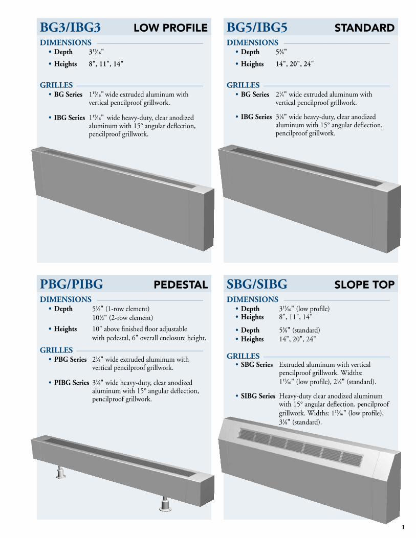
BG3/IBG3 LOW PROFILE DIMENSIONS ––––––––––––––––––––––––––
• Depth 315⁄16"
• Heights 8", 11", 14"
GRILLES –––––––––––––––––––––––––––––––• BG Series 115⁄16" wide extruded aluminum with
vertical pencilproof grillwork.
• IBG Series 115⁄16" wide heavy-duty, clear anodized aluminum with 15° angular deflection, pencilproof grillwork.
BG5/IBG5 STANDARDDIMENSIONS ––––––––––––––––––––––––––
• Depth 53⁄8"
• Heights 14",20",24"
GRILLES –––––––––––––––––––––––––––––––• BG Series 21⁄4" wide extruded aluminum with
vertical pencilproof grillwork.
• IBG Series 31⁄8" wide heavy-duty, clear anodized aluminum with 15° angular deflection, pencilproof grillwork.
PBG/PIBG PEDESTAL DIMENSIONS ––––––––––––––––––––––––––
• Depth 51⁄2" (1-row element) 101⁄2" (2-row element)
• Heights 10" above finished floor adjustable with pedestal, 6" overall enclosure height.
GRILLES –––––––––––––––––––––––––––––––• PBG Series 21⁄4" wide extruded aluminum with
vertical pencilproof grillwork.
• PIBG Series 31⁄8" wide heavy-duty, clear anodized aluminum with 15° angular deflection, pencilproof grillwork.
SBG/SIBG SLOPE TOPDIMENSIONS ––––––––––––––––––––––––––
• Depth 315⁄16" (low profile) • Heights 8", 11", 14"
• Depth 53⁄8" (standard)• Heights 14", 20", 24"
GRILLES –––––––––––––––––––––––––––––––• SBG Series Extruded aluminum with vertical
pencilproof grillwork. Widths: 115⁄16" (low profile), 21⁄4" (standard).
• SIBG Series Heavy-duty clear anodized aluminum with 15° angular deflection, pencilproof grillwork. Widths: 115⁄16" (low profile), 31⁄8" (standard).

2
IBG3PIPE SIZE
FIN SIZE A BSTEEL COPPER
N/A3⁄4", 1",
11⁄4" 23⁄4" x 4" 8" 11" 14"
315⁄16"1", 11⁄4"
3⁄4", 1", 11⁄4"
31⁄4" x 31⁄4"
1-15/16"
"A"
"B"
CENTERLINES ARE BASED ON 1" COPPER TUBE
2-1/16"
*
WALL
4" MIN.
2-7/8"
*
FLOOR
BG3/IBG3LOW PROFILE
APPLICATION ––––––––––––––––Rittling’s Low Profile Bargrille Enclosureprovides an attractive architectural design with a slimline appearance and a depth of less than 4".
ENCLOSURE ––––––––––––––––––• 14-to18-gaugeCRS,phosphatized
with painted finish.• 1'-8'lengthsin6"increments.• Powdercoatedfinishindecorator
colors available.• 8",11"or14"standardheights.• Customheights:6"-36"available.• Availablein18-gaugeand16-gauge
stainless steel.
GRILLE ––––––––––––––––––––––• BG:standardaluminumextrusion,
etched finishes, pencilproof.• IBG:heavy-dutyaluminumextrusion,
R-204 clear anodized finish, 15° grille deflection, pencilproof.
ELEMENT ––––––––––––––––––––• Steelorcopper/aluminum.• 1'-12'lengthsin6"increments
(10-foot maximum length for steel).• Galvanizedfins:.032"thick.• Aluminumfins:.016"thick.
MOUNTING ––––––––––––––––––• Mountingchannel.• Optional20-gaugegalvannealed
steel full back panel (18-gauge available).
HANGERS ––––––––––––––––––––• Self-gauging,snapfit,expansion
cradle with positive-locking, bottom-mounting clip provide easy installation as well as security.
• 16-gaugeGalvannealedsteel.• Slidecradlewillaccommodate13⁄4"
linear expansion for quiet operation.
JOINTS –––––––––––––––––––––––• Internaljogglejoinersprovidehairline
joints without any external fasteners.
DAMPER –––––––––––––––––––––• (Optional)durableknob,security
tamper proof or aluminum slide available (IBG only).
• Notavailableon8"height.
1-15/16"
2-7/8"
4" MIN.
WALL
*
2-1/16"
CENTERLINES ARE BASED ON 1" COPPER TUBE*
"B"
"A"
FLOOR
Cutaway view of IBG3 enclosure showing3 1⁄4" x 31⁄4" fin configuration.
BG3PIPE SIZE
FIN SIZE A BSTEEL COPPER
N/A3⁄4", 1",
11⁄4" 23⁄4" x 4" 8" 11" 14"
315⁄16"1", 11⁄4"
3⁄4", 1", 11⁄4"
31⁄4" x 31⁄4"
MOUNTINGCHANNEL DETAIL
BRACKET
ENCLOSURE
POSITIVE LOCKING BOTTOM MOUNTING CLIP DETAIL
ENCL
OSUR
EFIN
TINNERMANNUT

3
2"
WALL
CENTERLINES ARE BASED ON 1" COPPER TUBE
"A"
4" MIN.
7/8"
* 3-3/4"
1-15/16"
3-15/16"
FLOOR
1-15/16"
"A"
1"
3-7/8"
* 6-3/4"
CENTERLINES ARE BASED ON 1" COPPER TUBE
2"
WALL
3-15/16"
FLOOR
NOTE: TodeterminecapacityratingsforBGVL3,BGHL3,derateBG3/IBG3ratingsby12.5%.
BGVL3/BGHL3LOW PROFILE
APPLICATION ––––––––––––––––Rittling’s Low Profile Bargrille Enclosureprovides an attractive architectural design with a slimline appearance and a depth of less than 4".
ENCLOSURE ––––––––––––––––––• 14 -to18-gaugeCRS,phosphatized
with painted finish.• 1'-8'lengthsin6"increments.• Powdercoatedfinishindecorator
colors available.• 11"or14"standardheights.• Customheights:10"-36"available.• Availablein18-gaugeand16-gauge
stainless steel.
GRILLE ––––––––––––––––––––––• BG:standardaluminumextrusion,
etched finishes, pencilproof.• IBG:heavy-dutyaluminumextrusion,
R-204 clear anodized finish, 15° grille deflection, pencilproof.
ELEMENT ––––––––––––––––––––• Steelorcopper/aluminum.• 1'-12'lengthsin6"increments
(10' maximum length for steel).• Galvanizedfins:.032"thick• Aluminumfins:.016"thick.
MOUNTING ––––––––––––––––––• Mountingchannel.• Optional20-gaugeGalvannealed
steel full back panel (18-gauge available).
• Urethanegasketforairsealavailable.
HANGERS ––––––––––––––––––––• 16-gaugeGalvannealedsteel.• Slidecradlewillaccommodate13⁄4"
linear expansion for quiet operation.
JOINTS –––––––––––––––––––––––• Internaljogglejoinersprovidehairline
joints without any external fasteners.
DAMPER –––––––––––––––––––––• (Optional)durableknob,security
tamper proof or aluminum slide available (IBG only).
BGVL3PIPE SIZE
FIN SIZE A BSTEEL COPPER
N/A 3⁄4", 1", 11⁄4" 23⁄4" x 4" 8" 11" 14"
315⁄16"1", 11⁄4" 3⁄4", 1", 11⁄4" 31⁄4" x 31⁄4"
BGHL3PIPE SIZE
FIN SIZE A BSTEEL COPPER
N/A 3⁄4", 1", 11⁄4" 23⁄4" x 4" 8" 11" 14"
315⁄16"1", 11⁄4" 3⁄4", 1", 11⁄4" 31⁄4" x 31⁄4"

4
IBGVL3/IBGHL3LOW PROFILE
APPLICATION ––––––––––––––––Rittling’s Low Profile Bargrille Enclosureprovides an attractive architectural design with a slimline appearance and a depth of less than 4".
ENCLOSURE ––––––––––––––––––• 14 -to18-gaugeCRS,phosphatized
with painted finish.• 1'-8'lengthsin6"increments.• Powdercoatedfinishindecorator
colors available.• 11"or14"standardheights.• Customheights:10"-36"available.• Availablein18-gaugeand16-gauge
stainless steel.
GRILLE ––––––––––––––––––––––• BG:standardaluminumextrusion,
etched finishes, pencilproof.• IBG:heavy-dutyaluminumextrusion,
R-204 clear anodized finish, 15° grille deflection, pencilproof.
ELEMENT ––––––––––––––––––––• Steelorcopper/aluminum.• 1'-12'lengthsin6"increments
(10-foot maximum length for steel).• Galvanizedfins:.032"thick.• Aluminumfins:.016"thick.
MOUNTING ––––––––––––––––––• Mountingchannel.• Optional20-gaugeGalvannealed
steel full back panel. (18-gauge available.)
• Urethanegasketforairsealavailable.
HANGERS ––––––––––––––––––––• 16-gaugeGalvannealedsteel.• Slidecradlewillaccommodate13⁄4"
linear expansion for quiet operation.
JOINTS –––––––––––––––––––––––• Internaljogglejoinersprovidehairline
joints without any external fasteners.
DAMPER –––––––––––––––––––––•(Optional)durableknoborsecurity
tamper proof available.
* 3-3/4"
7/8"
4" MIN.
"A"
*CENTERLINES ARE BASED ON 1" COPPER TUBE
WALL
2"
3-15/16"
1-15/16"
FLOOR
3-15/16"
1-15/16"
1"
3-7/8"
* 6-3/4"
* CENTERLINES ARE BASED ON 1" COPPER TUBE
2"
WALL
"A"
FLOOR
NOTE:TodeterminecapacityratingsforIBGVL3andIBGHL3,derateBG3/IBG3ratingsby12.5%.
IBGHL3PIPE SIZE
FIN SIZE A BSTEEL COPPER
N/A 3⁄4", 1", 11⁄4" 23⁄4" x 4" 8" 11" 14"
315⁄16"1", 11⁄4" 3⁄4", 1", 11⁄4" 31⁄4" x 31⁄4"
IBGVL3PIPE SIZE
FIN SIZE A BSTEEL COPPER
N/A 3⁄4", 1", 11⁄4" 23⁄4" x 4" 8" 11" 14"
315⁄16"1", 11⁄4" 3⁄4", 1", 11⁄4" 31⁄4" x 31⁄4"

5
GUARANTEED RATINGSIn BTU/hr per active (finned) lineal foot of tube at entering air temperature of 65° F
FINNED TUBE MODEL
Rows of Finned Tube
(On 6" Centers)
Enclosure Height
(in inches)
Recommended Minimum Installed Height
(in inches)
EDR* (ft2⁄ ft)
STEAM HEAT HOT WATER HEAT
215° Factor of
1.00
190° Factor of
0.78
180° Factor of
0.69
170° Factor of
0.61
160° Factor of
0.53
STEEL FINNED TUBING
1" D
IA. S
TEE
L 1" S – 31⁄4" x 31⁄4"– 321 8 12 3.20 770 600 530 470 4101 11 15 3.40 820 640 570 500 4301 14 18 3.50 840 660 580 510 4502 14 18 4.80 1150 900 790 700 610
1" S – 31⁄4" x 31⁄4"– 401 8 12 3.50 840 660 580 510 4501 11 15 3.80 920 720 630 560 4901 14 18 4.00 960 750 660 590 5102 14 18 5.40 1300 1010 900 790 690
1" S – 31⁄4" x 31⁄4"–481 8 12 4.00 960 748 660 590 5101 11 15 4.30 1030 803 710 630 5501 14 18 4.50 1080 842 750 660 5702 14 18 610 1470 1146 1010 900 780
11 ⁄4"
DIA
. STE
EL 11⁄4" S – 31⁄4" x 31⁄4"–32
1 8 12 3.10 750 590 520 460 4001 11 15 3.30 800 620 550 490 4201 14 18 3.40 820 640 570 500 5302 14 18 4.70 1130 880 780 690 600
11⁄4" S – 31⁄4" x 31⁄4"– 401 8 12 3.40 820 640 570 500 4301 11 15 3.80 900 700 620 550 4801 14 18 3.90 940 730 650 570 5002 14 18 5.30 1270 990 880 770 670
11⁄4" S – 31⁄4" x 31⁄4"– 481 8 12 3.90 940 730 650 570 5001 11 15 4.20 1010 790 700 620 5401 14 18 4.40 1060 830 730 650 5602 14 18 6.00 1440 1120 990 880 760
COPPER FINNED TUBING
3 ⁄4"
DIA
. CO
PP
ER 3⁄4" C – 23⁄4" x 4"–32
1 8 12 4.30 1030 800 710 630 5401 11 15 4.60 1100 860 760 670 5801 14 18 4.90 1170 910 810 710 6202 14 18 6.70 1600 1250 1110 980 850
3⁄4" C – 23⁄4" x 4"– 40 1 8 12 4.70 1130 880 780 690 6001 11 15 5.10 1220 950 840 740 6501 14 18 5.40 1290 1010 890 790 6802 14 18 9.30 2220 1230 1080 940 1176
3⁄4" C – 23⁄4" x 4"–48 1 8 12 5.10 1220 950 840 740 6501 11 15 5.60 1340 1050 920 870 7101 14 18 5.90 1410 1100 970 860 7502 14 18 8.00 1930 1500 1330 1180 1020
1" D
IA. C
OP
PE
R 1" C – 23⁄4" x 4"–32 1 8 12 4.20 1010 790 700 620 5401 11 15 4.50 1080 840 750 660 5701 14 18 4.80 1150 900 730 700 6102 14 18 6.60 1580 1230 1090 960 840
1" C – 23⁄4" x 4"–40 1 8 12 4.60 1110 870 770 680 5901 11 15 5.00 1200 940 830 730 6401 14 18 5.30 1270 990 880 770 6702 14 18 7.30 1750 1370 1210 1070 930
1" C – 23⁄4" x 4"–48 1 8 12 5.00 1200 940 830 730 6401 11 15 5.50 1320 1030 910 810 7001 14 18 5.80 1390 1080 960 850 7402 14 18 7.90 1900 1480 1310 1160 1010
*EDR - Equivalent Direct Radiation area (for steam heat) per active (finned) lineal foot of tube.
IMPORTANT RATING INFORMATION – Guaranteed ratings based on:• Installationatheightshown.(Lower heights are not recommended; for greater heights refer to Table 1 on page 19.)• Enteringairtemperatureof65°F.(For other temperatures, refer to Table 2 or Table 3 on page 19.)• Steamatnominal1(actual0.9)PSIGand215°F. (For other conditions, refer to Table 2 on page 19.)•Wateraveragetemperature(°F)shownandvelocityof3FPSormore. (For lower velocities, see Figure 1 on page 20.)
Figure1onpage20depictstheinterrelationsofwatervelocities,flowrates,pressuredrops,andtemperaturedropswithrespecttototalBTU requirements for all four tube diameters.LinearexpansionofsteelandcopperfinnedtubewithtemperatureisshowninFigure4onpage21.
(continued on next page)
BG3/IBG3LOW PROFILE

6
GUARANTEED RATINGSIn BTU/hr per active (finned) lineal foot of tube at entering air temperature of 65° F
FINNED TUBE MODEL
Rows of Finned Tube
(On 6" Centers)
Enclosure Height
(in inches)
Recommended Minimum Installed Height
(in inches)
EDR* (ft2⁄ ft)
STEAM HEAT HOT WATER HEAT
215° Factor of
1.00
190° Factor of
0.78
180° Factor of
0.69
170° Factor of
0.61
160° Factor of
0.53
COPPER FINNED TUBING
11 ⁄4"
DIA
. CO
PPER 11⁄4" C – 23⁄4" x 4"–32
1 8 12 4.00 960 750 660 590 5101 11 15 4.30 1030 800 710 630 5501 14 18 4.60 1110 870 770 680 5902 14 18 6.30 1510 1180 1040 920 800
11⁄4" C – 23⁄4" x 4"–401 8 12 4.50 1080 840 750 660 5701 11 15 4.80 1150 900 790 700 6101 14 18 5.10 1220 950 840 740 6502 14 18 7.00 1680 1310 1160 1020 890
11⁄4" C – 23⁄4" x 4"– 481 8 12 5.00 1180 920 810 720 6301 11 15 5.30 1270 990 880 770 6701 14 18 5.60 1340 1050 920 820 7102 14 18 7.70 1850 1440 1280 1130 980
3 ⁄4"
DIA
. CO
PP
ER 3⁄4" C – 31⁄4" x 31⁄4"– 32
1 8 12 4.10 980 760 680 600 5201 11 15 4.40 1050 820 720 640 5601 14 18 4.70 1130 880 780 690 6002 14 18 6.40 1540 1200 1060 940 820
3⁄4" C – 31⁄4" x 31⁄4"– 401 8 12 4.50 1080 840 750 660 5701 11 15 4.90 1170 910 810 710 6201 14 18 5.10 1240 970 860 760 6602 14 18 7.10 1710 1330 1180 1040 910
3⁄4" C – 31⁄4" x 31⁄4"– 481 8 12 5.00 1200 940 830 730 6401 11 15 5.40 1300 1010 900 790 6901 14 18 5.40 1370 1070 950 840 7302 14 18 7.90 1890 1480 1300 1150 1000
1" D
IA. C
OP
PE
R 1" C – 31⁄4" x 31⁄4"–321 8 12 4.00 960 750 660 590 5101 11 15 4.30 1030 800 710 630 5501 14 18 4.60 1110 870 770 680 5902 14 18 6.30 1510 1180 1040 920 800
1" C – 31⁄4" x 31⁄4"– 40 1 8 12 4.40 1060 830 730 650 5601 11 15 4.80 1150 900 790 700 6101 14 18 5.10 1220 950 840 740 6502 14 18 7.00 1680 1310 1160 1020 890
1" C – 31⁄4" x 31⁄4"– 48 1 8 12 4.90 1180 920 810 720 6301 11 15 5.30 1270 990 880 770 6701 14 18 5.60 1340 1050 920 820 7102 14 18 7.70 1850 1440 1280 1130 980
11 ⁄4"
DIA
. CO
PPER 11⁄4" C – 31⁄4" x 31⁄4"– 32
1 8 12 3.50 850 660 590 520 4501 11 15 3.80 920 720 630 560 4901 14 18 4.00 960 750 660 590 5102 14 18 5.50 1320 1030 910 810 700
11⁄4" C – 31⁄4" x 31⁄4"– 40 1 8 12 4.40 1060 830 730 650 5601 11 15 4.70 1130 880 780 690 6001 14 18 5.00 1200 940 830 730 6402 14 18 6.90 1660 1290 1150 1010 880
11⁄4" C – 31⁄4" x 31⁄4"–48 1 8 12 4.80 1150 900 790 700 6101 11 15 5.20 1250 980 860 760 6601 14 18 5.50 1320 1030 910 810 7002 14 18 7.50 1800 1400 1240 1100 950
*EDR - Equivalent Direct Radiation area (for steam heat) per active (finned) lineal foot of tube.
IMPORTANT RATING INFORMATION – Guaranteed ratings based on:• Installationatheightshown.(Lower heights are not recommended; for greater heights refer to Table 1 on page 19.)• Enteringairtemperatureof65°F.(For other temperatures, refer to Table 2 or Table 3 on page 19.)• Steamatnominal1(actual0.9)PSIGand215°F. (For other conditions, refer to Table 2 on page 19.)•Wateraveragetemperature(°F)shownandvelocityof3FPSormore. (For lower velocities, see Figure 1 on page 20.)
Figure1onpage20depictstheinterrelationsofwatervelocities,flowrates,pressuredrops,andtemperaturedropswithrespecttototalBTU requirements for all four tube diameters.LinearexpansionofsteelandcopperfinnedtubewithtemperatureisshowninFigure4onpage21.
BG3/IBG3LOW PROFILE

7
BG5/IBG5STANDARD
APPLICATION ––––––––––––––––Rittling’sStandardBargrilleEnclosuresprovide high output in an attractive architectural design with a depth of 53⁄8".
ENCLOSURE ––––––––––––––––––• 14-to18-gaugeCRS,phosphatized
with painted finish.• 1'-8'lengthsin6"increments.• Powdercoatedfinishindecorator
colors available.• 14",20"or24"standardheights.• Customheights:6"-36"available.• Availablein18-gaugeand16-gauge
stainless steel.
GRILLE ––––––––––––––––––––––• BG:standardaluminumextrusion,
etched finishes, pencilproof.• IBG:heavy-dutyaluminumextrusion,
R-204 clear anodized finish, 15° grille deflection, pencilproof.
ELEMENT ––––––––––––––––––––• Steelorcopper/aluminum.• 1'-12'lengthsin6"increments
(10-foot maximum length for steel).• Galvanizedfins:.032"thick.• Aluminumfins:.016"thick.
MOUNTING ––––––––––––––––––• Mountingchannel.• Optional20-gaugeGalvannealed
steel full back panel (18-gauge available).
• Urethanegasketforairsealavailable.
HANGERS ––––––––––––––––––––• Self-gauging,snapfit,expansion
cradle with positive-locking, bottom-mounting clip provide easy installation as well as security.
• 16-gaugeGalvannealedsteel.• Slidecradlewillaccommodate13⁄4"
linear expansion for quiet operation.
JOINTS –––––––––––––––––––––––• Internaljogglejoinersprovidehairline
joints without any external fasteners.
DAMPER –––––––––––––––––––––• (Optional)durableknob,security
tamper proof or aluminum slide available (IBG only).
1:1
2-9/32"
WALL
* CENTERLINES ARE BASED ON 1" COPPER TUBE
4" MIN
2-7/8"
6"
6"
*
"A"
2-5/8"
"B"
FLOOR
WALL
*CENTERLINES ARE BASED ON 1" COPPER TUBE
4" MIN
2-7/8"
6"
6"
*
"A"
2-5/8"
3-7/32"
"B"
FLOOR
Cutaway view of IBG5 enclosure showing4 1⁄4" x 4 1⁄4" fin configuration.
BG5PIPE SIZE
FIN SIZE A BSTEEL COPPER
N/A3⁄4", 1",
11⁄4" 23⁄4" x 4" 14"
20"
24"
53⁄8"1", 11⁄4"
3⁄4", 1", 11⁄4"
31⁄4" x 31⁄4"
1", 11⁄4", 2"
3⁄4", 1", 11⁄4"
41⁄4" x 41⁄4"
MOUNTINGCHANNEL DETAIL
BRACKET
ENCLOSURE
POSITIVE LOCKING BOTTOM MOUNTING CLIP DETAIL
ENCL
OSUR
EFIN
TINNERMANNUT
IBG5PIPE SIZE
FIN SIZE A BSTEEL COPPER
N/A3⁄4", 1",
11⁄4" 23⁄4" x 4" 14"
20"
24"
53⁄8"1", 11⁄4"
3⁄4", 1", 11⁄4"
31⁄4" x 31⁄4"
1", 11⁄4", 2"
3⁄4", 1", 11⁄4"
41⁄4" x 41⁄4"
8
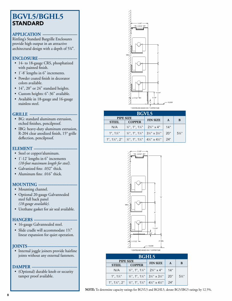
BGVL5/BGHL5STANDARD
APPLICATION ––––––––––––––––Rittling’sStandardBargrilleEnclosuresprovide high output in an attractive architectural design with a depth of 53⁄8".
ENCLOSURE ––––––––––––––––––• 14-to18-gaugeCRS,phosphatized
with painted finish.• 1'-8'lengthsin6"increments.• Powdercoatedfinishindecorator
colors available.• 14",20"or24"standardheights.• Customheights:6"-36"available.• Availablein18-gaugeand16-gauge
stainless steel.
GRILLE ––––––––––––––––––––––• BG:standardaluminumextrusion,
etched finishes, pencilproof.• IBG:heavy-dutyaluminumextrusion,
R-204 clear anodized finish, 15° grille deflection, pencilproof.
ELEMENT ––––––––––––––––––––• Steelorcopper/aluminum.• 1'-12'lengthsin6"increments
(10-foot maximum length for steel).• Galvanizedfins:.032"thick.• Aluminumfins:.016"thick.
MOUNTING ––––––––––––––––––• Mountingchannel.•Optional20-gaugeGalvannealed
steel full back panel (18-gauge available).
• Urethanegasketforairsealavailable.
HANGERS ––––––––––––––––––––• 16-gaugeGalvannealedsteel.• Slidecradlewillaccommodate13⁄4"
linear expansion for quiet operation.
JOINTS –––––––––––––––––––––––• Internaljogglejoinersprovidehairline
joints without any external fasteners.
DAMPER –––––––––––––––––––––• (Optional)durableknoborsecurity
tamper proof available.
2-9/32"
5-3/8"
7/8"
4" MIN.
* 3-3/4"
2-17/32"
6"
WALL
* CENTERLINES BASED ON 1" COPPER TUBE
6"
"A"
FLOOR
2-17/32"
6"
* CENTERLINES BASED ON 1" COPPER TUBE
* 6-3/4"
1"
3-7/8"
6"
5-3/8"
WALL
2-9/32"
FLOOR
NOTE:TodeterminecapacityratingsforBGVL5andBGHL5,derateBG5/IBG5ratingsby12.5%.
BGVL5PIPE SIZE
FIN SIZE A BSTEEL COPPER
N/A 3⁄4", 1", 11⁄4" 23⁄4" x 4" 14"
20"
24"
53⁄8"1", 11⁄4" 3⁄4", 1", 11⁄4" 31⁄4" x 31⁄4"
1", 11⁄4", 2" 3⁄4", 1", 11⁄4" 41⁄4" x 41⁄4"
BGHL5PIPE SIZE
FIN SIZE A BSTEEL COPPER
N/A 3⁄4", 1", 11⁄4" 23⁄4" x 4" 14"
20"
24"
53⁄8"1", 11⁄4" 3⁄4", 1", 11⁄4" 31⁄4" x 31⁄4"
1", 11⁄4", 2" 3⁄4", 1", 11⁄4" 41⁄4" x 41⁄4"
9
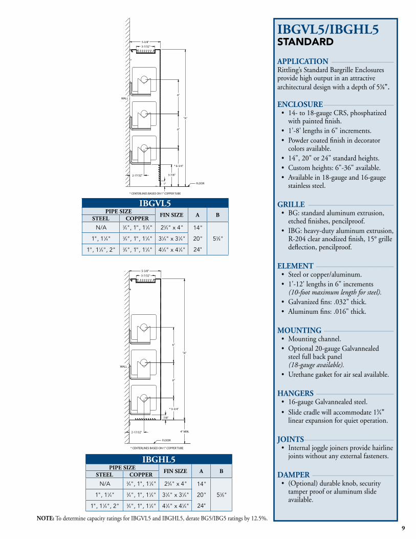
NOTE:TodeterminecapacityratingsforIBGVL5andIBGHL5,derateBG5/IBG5ratingsby12.5%.
IBGVL5/IBGHL5STANDARD
APPLICATION ––––––––––––––––Rittling’sStandardBargrilleEnclosuresprovide high output in an attractive architectural design with a depth of 53⁄8".
ENCLOSURE ––––––––––––––––––• 14-to18-gaugeCRS,phosphatized
with painted finish.• 1'-8'lengthsin6"increments.• Powdercoatedfinishindecorator
colors available.• 14",20"or24"standardheights.• Customheights:6"-36"available.• Availablein18-gaugeand16-gauge
stainless steel.
GRILLE ––––––––––––––––––––––• BG:standardaluminumextrusion,
etched finishes, pencilproof.• IBG:heavy-dutyaluminumextrusion,
R-204 clear anodized finish, 15° grille deflection, pencilproof.
ELEMENT ––––––––––––––––––––• Steelorcopper/aluminum.• 1'-12'lengthsin6"increments
(10-foot maximum length for steel).• Galvanizedfins:.032"thick.• Aluminumfins:.016"thick.
MOUNTING ––––––––––––––––––• Mountingchannel.• Optional20-gaugeGalvannealed
steel full back panel (18-gauge available).
• Urethanegasketforairsealavailable.
HANGERS ––––––––––––––––––––• 16-gaugeGalvannealedsteel.• Slidecradlewillaccommodate13⁄4"
linear expansion for quiet operation.
JOINTS –––––––––––––––––––––––• Internaljogglejoinersprovidehairline
joints without any external fasteners.
DAMPER –––––––––––––––––––––• (Optional)durableknob,security
tamper proof or aluminum slide available.
"A"
6"
* CENTERLINES BASED ON 1" COPPER TUBE
WALL
6"
2-17/32"
* 3-3/4"
4" MIN.
7/8"
3-7/32"
5-3/8"
FLOOR
"A"
WALL
6"
3-7/8"
1"
* 6-3/4"
* CENTERLINES BASED ON 1" COPPER TUBE
6"
2-17/32"
5-3/8"
3-7/32"
FLOOR
IBGVL5PIPE SIZE
FIN SIZE A BSTEEL COPPER
N/A 3⁄4", 1", 11⁄4" 23⁄4" x 4" 14"
20"
24"
53⁄8"1", 11⁄4" 3⁄4", 1", 11⁄4" 31⁄4" x 31⁄4"
1", 11⁄4", 2" 3⁄4", 1", 11⁄4" 41⁄4" x 41⁄4"
IBGHL5PIPE SIZE
FIN SIZE A BSTEEL COPPER
N/A 3⁄4", 1", 11⁄4" 23⁄4" x 4" 14"
20"
24"
53⁄8"1", 11⁄4" 3⁄4", 1", 11⁄4" 31⁄4" x 31⁄4"
1", 11⁄4", 2" 3⁄4", 1", 11⁄4" 41⁄4" x 41⁄4"

10
GUARANTEED RATINGSIn BTU/hr per active (finned) lineal foot of tube at entering air temperature of 65° F
FINNED TUBE MODEL
Rows of Finned Tube
(On 6" Centers)
Enclosure Height
(in inches)
Recommended Minimum Installed Height
(in inches)
EDR* (ft2⁄ ft)
STEAM HEAT HOT WATER HEAT
215° Factor of
1.00
190° Factor of
0.78
180° Factor of
0.69
170° Factor of
0.61
160° Factor of
0.53
STEEL FINNED TUBING
1" D
IA. S
TEE
L
1" S – 31⁄4" x 31⁄4"– 32
1 14 18 4.00 960 750 660 580 5101 20 24 4.10 980 760 680 600 5202 20 24 6.20 1490 1160 1030 910 7901 24 28 4.30 1030 800 710 630 5402 24 28 6.60 1570 1220 1080 960 8303 24 28 7.60 1820 1420 1250 1110 960
1" S – 31⁄4" x 31⁄4"– 40
1 14 18 4.50 1080 840 740 660 5701 20 24 4.80 1150 900 790 700 6102 20 24 6.80 1640 1280 1130 1000 8701 24 28 5.00 1200 940 830 730 6402 24 28 7.10 1710 1330 1180 1040 9103 24 28 8.30 1980 1540 1370 1210 820
1" S – 31⁄4" x 31⁄4"–48
1 14 18 5.00 1200 940 830 730 8401 20 24 5.60 1350 1050 930 820 7102 20 24 7.80 1870 1460 1290 1140 9901 24 28 5.80 1400 1090 970 850 7402 24 28 7.80 1860 1450 1280 1130 9803 24 28 8.90 2130 1660 1470 1300 1130
11 ⁄4"
DIA
. STE
EL
11⁄4" S – 31⁄4" x 31⁄4"–32
1 14 18 3.90 940 730 650 570 5001 20 24 4.00 960 750 660 590 5102 20 24 6.10 1460 1140 1010 890 7701 24 28 4.20 1010 790 700 620 5402 24 28 6.40 1540 1200 1060 940 8203 24 28 7.40 1780 1390 1230 1090 940
11⁄4" S – 31⁄4" x 31⁄4"– 40
1 14 18 4.40 1060 830 730 650 5601 20 24 4.70 1130 880 780 690 6002 20 24 6.70 1610 1260 1110 980 8501 24 28 4.90 1180 920 810 720 6302 24 28 7.00 1680 1310 1160 1020 8903 24 28 8.10 1940 1510 1340 1180 1030
11⁄4" S – 31⁄4" x 31⁄4"– 48
1 14 18 4.90 1180 920 810 720 6301 20 24 5.50 1320 1030 910 810 7002 20 24 7.40 1780 1390 1230 1090 9401 24 28 5.70 1370 1070 950 840 7302 24 28 7.60 1820 1420 1260 1110 9603 24 28 8.70 2090 1630 1440 1270 1110
*EDR - Equivalent Direct Radiation area (for steam heat) per active (finned) lineal foot of tube.
IMPORTANT RATING INFORMATION – Guaranteed ratings based on:• Installationatheightshown.(Lower heights are not recommended; for greater heights refer to Table 1 on page 19.)• Enteringairtemperatureof65°F.(For other temperatures, refer to Table 2 or Table 3 on page 19.)• Steamatnominal1(actual0.9)PSIGand215°F. (For other conditions, refer to Table 2 on page 19.)•Wateraveragetemperature(°F)shownandvelocityof3FPSormore. (For lower velocities, see Figure 1 on page 20.)
Figure1onpage20depictstheinterrelationsofwatervelocities,flowrates,pressuredrops,andtemperaturedropswithrespecttototalBTU requirements for all four tube diameters.LinearexpansionofsteelandcopperfinnedtubewithtemperatureisshowninFigure4onpage21.
(continued on next page)
BG5/IBG5STANDARD

11
GUARANTEED RATINGSIn BTU/hr per active (finned) lineal foot of tube at entering air temperature of 65° F
FINNED TUBE MODEL
Rows of Finned Tube
(On 6" Centers)
Enclosure Height
(in inches)
Recommended Minimum Installed Height
(in inches)
EDR* (ft2⁄ ft)
STEAM HEAT HOT WATER HEAT
215° Factor of
1.00
190° Factor of
0.78
180° Factor of
0.69
170° Factor of
0.61
160° Factor of
0.53
STEEL FINNED TUBING
1" D
IA. S
TEE
L
1" S – 41⁄4" x 41⁄4"– 32
1 14 18 5.80 1400 1090 970 850 7401 20 24 6.10 1450 1130 1000 890 7702 20 24 9.00 2150 1630 1480 1310 11401 24 28 6.10 1490 1160 1030 910 7902 24 28 9.40 2250 1760 1550 1370 11903 24 28 10.10 2590 2020 1790 1580 1370
1" S – 41⁄4" x 41⁄4"– 40
1 14 18 6.60 1570 1220 1080 960 8301 20 24 7.10 1690 1310 1170 1030 9002 20 24 9.90 2380 1860 1640 1450 12601 24 28 7.20 1730 1350 1200 1060 9202 24 28 10.30 2470 1930 1700 1510 13103 24 28 11.80 2840 2220 1960 1730 1510
1" S – 41⁄4" x 41⁄4"–48
1 14 18 7.30 1760 1370 1210 1070 9301 20 24 8.20 1960 1530 1350 1200 10402 20 24 10.90 2620 2050 1810 1600 13901 24 28 8.40 2010 1570 1390 1230 10702 24 28 11.30 2710 2110 1870 1650 14403 24 28 13.05 3130 2440 2160 1910 1660
11 ⁄4"
DIA
. STE
EL
11⁄4" S – 41⁄4" x 41⁄4"–32
1 14 18 5.70 1370 1070 950 840 7301 20 24 5.90 1420 1110 980 870 7502 20 24 8.80 2110 1650 1460 1290 11201 24 28 6.10 1460 1140 1010 890 7702 24 28 9.20 2210 1720 1520 1350 11703 24 28 10.60 2540 1980 1750 1550 1350
11⁄4" S – 41⁄4" x 41⁄4"– 40
1 14 18 6.40 1540 1200 1060 940 8201 20 24 6.90 1660 1290 1150 1010 8802 20 24 9.70 2330 1820 1610 1420 12301 24 28 7.10 1700 1330 1170 1040 9002 24 28 10.10 2420 1890 1670 1480 12803 24 28 11.60 2780 2170 1920 1700 1470
11⁄4" S – 41⁄4" x 41⁄4"– 48
1 14 18 7.20 1730 1350 1190 1060 9201 20 24 8.00 1920 1500 1320 1170 10202 20 24 10.70 2570 2000 1770 1570 13601 24 28 8.20 1970 1540 1360 1200 10402 24 28 11.10 2660 2070 1840 1620 14103 24 28 12.80 3070 2390 2120 1870 1630
2" D
IA. S
TEE
L
2" S – 41⁄4" x 41⁄4"–32
1 14 18 5.70 1370 1070 950 840 7301 20 24 6.00 1430 1120 990 870 7602 20 24 8.60 2070 1610 1430 1260 11001 24 28 6.10 1470 1150 1010 900 7802 24 28 8.90 2140 1670 1480 1310 11303 24 28 10.20 2450 1910 1690 1490 1300
2" S – 41⁄4" x 41⁄4"– 40
1 14 18 6.50 1560 1220 1080 950 8301 20 24 6.80 1630 1270 1120 990 8602 20 24 9.30 2230 1740 1540 1360 11801 24 28 7.20 1730 1350 1190 1060 9202 24 28 9.80 2350 1830 1620 1430 12503 24 28 11.30 2710 2110 1870 1650 1440
2" S – 41⁄4" x 41⁄4"– 48
1 14 18 7.40 1780 1390 1230 1090 9401 20 24 7.70 1850 1440 1280 1130 9802 20 24 10.00 2400 1870 1660 1460 12701 24 28 8.30 1990 1550 1370 1210 10502 24 28 10.60 2540 1980 1750 1550 13503 24 28 12.20 2930 2290 2020 1790 1550
*EDR - Equivalent Direct Radiation area (for steam heat) per active (finned) lineal foot of tube.
IMPORTANT RATING INFORMATION – See Page 10.(continued on next page)
BG5/IBG5STANDARD

12
GUARANTEED RATINGSIn BTU/hr per active (finned) lineal foot of tube at entering air temperature of 65° F
FINNED TUBE MODEL
Rows of Finned Tube
(On 6" Centers)
Enclosure Height
(in inches)
Recommended Minimum Installed Height
(in inches)
EDR* (ft2⁄ ft)
STEAM HEAT HOT WATER HEAT
215° Factor of
1.00
190° Factor of
0.78
180° Factor of
0.69
170° Factor of
0.61
160° Factor of
0.53
COPPER FINNED TUBING
3 ⁄4"
DIA
. CO
PP
ER
3⁄4" C – 23⁄4" x 4"– 32
1 14 18 5.30 1280 1000 890 780 6801 20 24 5.90 1400 1090 970 860 7402 20 24 7.70 1860 1450 1280 1130 9901 24 28 6.10 1470 1150 1010 900 7802 24 28 8.50 2050 1600 1410 1250 10903 24 28 9.90 2360 1840 1630 1440 1260
3⁄4" C – 23⁄4" x 4"– 40
1 14 18 5.90 1430 1120 990 880 7601 20 24 6.60 1590 1240 1100 970 8402 20 24 8.00 1930 1510 1330 1180 10201 24 28 7.00 1690 1320 1170 1030 9002 24 28 9.00 2170 1690 1500 1330 11503 24 28 10.50 2510 1960 1730 1530 1330
3⁄4" C – 23⁄4" x 4"– 48
1 14 18 6.50 1570 1220 1080 960 8301 20 24 7.40 1790 1400 1240 1100 9502 20 24 8.40 2030 1590 1400 1240 10801 24 28 7.80 1880 1470 1300 1150 10002 24 28 9.50 2270 1770 1570 1390 12103 24 28 10.90 2600 2030 1800 1590 1380
3 ⁄4"
DIA
. CO
PP
ER
3⁄4" C – 41⁄4" x 41⁄4"–32
1 14 18 6.80 1620 1300 1120 990 8601 20 24 7.20 1720 1340 1190 1050 9102 20 24 10.60 2530 1970 1750 1540 13401 24 28 7.50 1800 1400 1240 1100 9502 24 28 11.70 2810 2190 1940 1710 14903 24 28 13.40 3210 2500 2210 1960 1700
3⁄4" C – 41⁄4" x 41⁄4"– 40
1 14 18 7.90 1900 1482 1310 1160 10101 20 24 8.60 2070 1610 1430 1260 11002 20 24 11.60 2770 2160 1910 1690 14701 24 28 9.00 2160 1680 1490 1320 11502 24 28 12.60 3020 2360 2080 1840 16003 24 28 14.50 3470 2710 2390 2120 1840
3⁄4" C – 41⁄4" x 41⁄4"– 48
1 14 18 8.50 2040 1590 1410 1240 10801 20 24 9.80 2340 1830 1610 1430 12402 20 24 13.60 3270 2550 2260 1990 17301 24 28 10.50 2510 1960 1730 1530 13302 24 28 14.70 3520 2750 2430 2150 18703 24 28 16.70 3940 3070 2720 2400 2090
1" D
IA. C
OP
PE
R
1" C – 23⁄4" x 4"–32
1 14 18 5.30 1270 990 880 770 6701 20 24 5.80 1390 1080 960 850 7402 20 24 7.70 1850 1440 1280 1130 9801 24 28 6.10 1460 1140 1010 890 7702 24 28 8.50 2040 1590 1410 1240 10803 24 28 9.80 2350 1830 1620 1430 1250
1" C – 23⁄4" x 4"– 40
1 14 18 5.90 1420 1110 980 870 7501 20 24 6.60 1580 1230 1090 960 8402 20 24 8.00 1920 1500 1320 1170 10201 24 28 7.00 1680 1310 1160 1020 8902 24 28 9.00 2160 1680 1490 1320 11403 24 28 10.40 2500 1950 1730 1530 1330
1" C – 23⁄4" x 4"– 48
1 14 18 6.50 1560 1190 1070 950 8301 20 24 7.40 1780 1390 1230 1090 9402 20 24 8.40 2020 1580 1390 1230 10701 24 28 7.80 1870 1460 1290 1140 9902 24 28 9.40 2260 1760 1560 1380 12003 24 28 10.80 2590 2020 1790 1580 1370
*EDR - Equivalent Direct Radiation area (for steam heat) per active (finned) lineal foot of tube.
IMPORTANT RATING INFORMATION – See Page 10.(continued on next page)
BG5/IBG5STANDARD

13
GUARANTEED RATINGSIn BTU/hr per active (finned) lineal foot of tube at entering air temperature of 65° F
FINNED TUBE MODEL
Rows of Finned Tube
(On 6" Centers)
Enclosure Height
(in inches)
Recommended Minimum Installed Height
(in inches)
EDR* (ft2⁄ ft)
STEAM HEAT HOT WATER HEAT
215° Factor of
1.00
190° Factor of
0.78
180° Factor of
0.69
170° Factor of
0.61
160° Factor of
0.53
COPPER FINNED TUBING
1" D
IA. C
OP
PE
R
1" C – 41⁄4" x 41⁄4"– 32
1 14 18 6.60 1590 1240 1100 970 8501 20 24 7.00 1690 1320 1200 1030 9002 20 24 10.40 2480 1930 1710 1510 13101 24 28 7.30 1760 1370 1220 1070 9302 24 28 11.50 2750 2150 1900 1680 14603 24 28 13.20 3150 2460 2170 1920 1670
1" C – 41⁄4" x 41⁄4"– 40
1 14 18 7.70 1860 1450 1280 1130 9901 20 24 8.40 2030 1580 1400 1240 10802 20 24 11.40 2720 2120 1880 1660 14401 24 28 8.80 2120 1650 1460 1290 11202 24 28 12.40 2960 2310 2040 1810 15703 24 28 14.20 3400 2650 2350 2070 1800
1" C – 41⁄4" x 41⁄4"– 48
1 14 18 8.30 2000 1560 1380 1220 10601 20 24 9.60 2290 1790 1580 1400 12102 20 24 13.40 3210 2500 2210 1960 17001 24 28 10.30 2460 1920 1700 1500 13002 24 28 14.40 3450 2690 2380 2100 18303 24 28 16.10 3860 3010 2670 2350 2050
11 ⁄4"
DIA
. CO
PP
ER
11⁄4" C – 23⁄4" x 4"–32
1 14 18 5.10 1220 950 840 740 6501 20 24 5.70 1370 1070 950 840 7302 20 24 7.60 1820 1420 1260 1110 9601 24 28 6.00 1440 1120 990 880 7602 24 28 8.40 2020 1580 1390 1230 10703 24 28 9.70 2330 1820 1610 1420 1230
11⁄4" C – 23⁄4" x 4"– 40
1 14 18 5.70 1370 1070 950 840 7301 20 24 6.40 1540 1200 1060 940 8202 20 24 7.90 1900 1480 1310 1160 10101 24 28 6.90 1660 1290 1150 1010 8802 24 28 8.90 2140 1670 1480 1310 11303 24 28 10.20 2450 1910 1690 1490 1300
11⁄4" C – 23⁄4" x 4"– 48
1 14 18 6.40 1540 1200 1060 940 8201 20 24 7.30 1750 1370 1210 1070 9302 20 24 8.30 1990 1550 1370 1210 10501 24 28 7.70 1850 1440 1280 1130 9802 24 28 9.30 2230 1740 1540 1360 11803 24 28 10.70 2570 2000 1770 1510 1360
11 ⁄4"
DIA
. CO
PP
ER
11⁄4" C – 41⁄4" x 41⁄4"–32
1 14 18 6.60 1580 1230 1090 960 8401 20 24 7.00 1680 1310 1160 1020 8902 20 24 10.30 2470 1920 1700 1510 13101 24 28 7.30 1750 1360 1200 1070 9302 24 28 11.40 2740 2140 1890 1670 14503 24 28 13.10 3140 2450 2170 1920 1660
11⁄4" C – 41⁄4" x 41⁄4"– 40
1 14 18 7.70 1850 1440 1280 1130 9801 20 24 8.40 2020 1570 1390 1230 10702 20 24 11.30 2710 2110 1870 1650 14401 24 28 8.80 2110 1640 1460 1290 11202 24 28 12.30 2950 2300 2040 1800 15603 24 28 14.10 3380 2640 2330 2060 1790
11⁄4" C – 41⁄4" x 41⁄4"– 48
1 14 18 8.25 1980 1540 1370 1210 10501 20 24 9.50 2280 1780 1570 1390 12102 20 24 13.25 3180 2480 2190 1940 16901 24 28 10.10 2410 1880 1660 1470 12802 24 28 14.10 3380 2640 2332 2060 17903 24 28 15.80 3780 2950 2610 2310 2000
*EDR - Equivalent Direct Radiation area (for steam heat) per active (finned) lineal foot of tube.
IMPORTANT RATING INFORMATION – See Page 10.
BG5/IBG5STANDARD

14
Cutaway view of PIBG enclosure showing4 1⁄4" x 4 1⁄4" fin configuration.
FIN
ENCLOSURE
DETAIL OF ENCLOSUREBOTTOM MOUNTING CLIP
PIBG10
PBG10
4" MIN
TYP.
2-3/4"
10-1/2"
6"WALL
1-1/4"MIN.
TYP.
2-13/16"
* CENTERLINES ARE BASED ON 1" COPPER TUBE
*
3-7/32"
FASTENERSBY OTHERS
SUPPORT BRACKET
FLOOR
BRACKETS PAINTED TO MATCH ENCLOSURE
TYP.2-9/32"
2-3/4"
10-1/2"
6"WALL
1-1/4"MIN.
TYP.
2-13/16"
* CENTERLINES ARE BASED ON 1" COPPER TUBE
*
4" MIN
FASTENERSBY OTHERS
SUPPORT BRACKET
FLOOR
BRACKETS PAINTED TO MATCH ENCLOSURE
PBG PIBG
PBG/PIBGPEDESTAL
APPLICATION ––––––––––––––––Rittling’s Pedestal Bargrille Enclosure offers a slimline appearance in a strong floor mounted enclosure.
ENCLOSURE ––––––––––––––––––• 14-to18-gaugeCRS,phosphatized
with painted finish.• 1'–8'lengthsin6"increments.• Powdercoatedfinishindecorator
colors available.• Availablein18-gaugeand16-gauge
stainless steel.• One-row,two-rowhigh,two-row
wide or many other custom configurations available.
GRILLE ––––––––––––––––––––––• PBG:standardaluminumextrusion,
etched finishes, pencilproof.• PIBG:heavy-dutyaluminumextrusion,
R-204 clear anodized finish, 15° grille deflection, pencilproof.
ELEMENT ––––––––––––––––––––• Steelorcopper/aluminum.• 1'-12'lengthsin6"increments
(10-foot maximum length for steel).• Galvanizedfins:.032"thick.• Aluminumfins:.016"thick.
MOUNTING ––––––––––––––––––• Standard3⁄4" pedestal with floor
flange.• Castaluminumfloorflangewith
setscrew adjustment (optional).• 3⁄16" x 11⁄2"U-shapedbottombracket
for 2-row application.• Enclosuremountstoacradletype
expansion bracket with positive-locking, bottom mounting clip to provide easy installation and security.
JOINTS –––––––––––––––––––––––• Internaljogglejoinersprovidehairline
joints without any external fasteners.

15
GUARANTEED RATINGSIn BTU/hr per active (finned) lineal foot of tube at entering air temperature of 65° F
FINNED TUBE MODEL
Rows of Finned Tube
(On 6" Centers)
Enclosure Height
(in inches)
Recommended Minimum Installed Height
(in inches)
EDR* (ft2⁄ ft)
STEAM HEAT HOT WATER HEAT
215° Factor of
1.00
190° Factor of
0.78
180° Factor of
0.69
170° Factor of
0.61
160° Factor of
0.53
STEEL FINNED TUBING
1" D
IA. S
TEE
L
1" S – 31⁄4" x 31⁄4"– 321 6 10 3.80 910 710 630 560 480
2W 6 10 6.90 1660 1290 1150 1010 8802H 12 16 5.70 1360 1060 940 830 720
1" S – 31⁄4" x 31⁄4"– 401 6 10 4.10 980 770 680 600 520
2W 6 10 7.20 1730 1350 1190 1060 9202H 12 16 6.20 1480 1160 1020 900 790
1" S – 31⁄4" x 31⁄4"–481 6 10 4.40 1050 820 720 640 560
2W 6 10 8.00 1910 1490 1320 1170 10102H 12 16 6.60 1570 1230 1080 960 830
11 ⁄4"
DIA
. STE
EL
11⁄4" S – 31⁄4" x 31⁄4"–321 6 10 3.70 890 700 610 540 470
2W 6 10 6.80 1630 1270 1120 990 8602H 12 16 5.60 1330 1040 920 810 700
11⁄4" S – 31⁄4" x 31⁄4"– 401 6 10 4.00 960 750 660 590 510
2W 6 10 7.10 1700 1330 1170 1040 9002H 12 16 6.10 1450 1130 1000 880 770
11⁄4" S – 31⁄4" x 31⁄4"– 481 6 10 4.30 1030 800 710 630 550
2W 6 10 7.80 1870 1460 1290 1140 9902H 12 16 6.40 1540 1200 1060 940 820
1" D
IA. S
TEE
L
1" S –41⁄4" x 41⁄4"–321 6 10 5.30 1280 1000 880 780 680
2W 6 10 9.80 2350 1830 1620 1430 12502H 12 16 7.50 1800 1400 1240 1100 950
1" S – 41⁄4" x 41⁄4"– 40 1 6 10 5.60 1330 1040 920 810 700
2W 6 10 10.40 2500 1950 1730 1530 10302H 12 16 8.00 1980 1540 1310 1210 1050
1" S – 41⁄4" x 41⁄4"–48 1 6 10 6.10 1470 1150 1010 900 780
2W 6 10 11.20 2690 2100 1860 1640 14302H 12 16 8.80 2120 1650 1460 1290 1120
11 ⁄4"
DIA
. STE
EL 11⁄4" S – 41⁄4" x 41⁄4"–32 1 6 10 5.20 1250 980 860 760 660
2W 6 10 9.60 2300 1790 1590 1400 12202H 12 16 7.30 1760 1370 1210 1070 930
11⁄4" S – 41⁄4" x 41⁄4"–40 1 6 10 5.40 1300 1010 900 790 690
2W 6 10 10.20 2450 1910 1690 1490 13902H 12 16 8.10 1940 1510 1340 118 1030
11⁄4" S – 41⁄4" x 41⁄4"–48 1 6 10 6.00 1440 1120 990 880 760
2W 6 10 11.00 2640 2060 1820 1610 14002H 12 16 8.70 2080 1620 1440 1270 1100
*EDR - Equivalent Direct Radiation area (for steam heat) per active (finned) lineal foot of tube. + Contact factory when ordering 11⁄4" copper, 1" steel and 11⁄4" steel elements to ensure proper fit up inside the enclosure. IMPORTANT RATING INFORMATION – Guaranteed ratings based on:• Installationatheightshown.(Lower heights are not recommended; for greater heights refer to Table 1 on page 19.)• Enteringairtemperatureof65°F.(For other temperatures, refer to Table 2 or Table 3 on page 19.)• Steamatnominal1(actual0.9)PSIGand215°F. (For other conditions, refer to Table 2 on page 19.)•Wateraveragetemperature(°F)shownandvelocityof3FPSormore. (For lower velocities, see Figure 1 on page 20.)
Figure1onpage20depictstheinterrelationsofwatervelocities,flowrates,pressuredrops,andtemperaturedropswithrespecttototalBTU requirements for all four tube diameters.LinearexpansionofsteelandcopperfinnedtubewithtemperatureisshowninFigure4onpage21.
(continued on next page)
PBG/PIBGPEDESTAL

16
GUARANTEED RATINGSIn BTU/hr per active (finned) lineal foot of tube at entering air temperature of 65° F
FINNED TUBE MODEL
Rows of Finned Tube
(On 6" Centers)
Enclosure Height
(in inches)
Recommended Minimum Installed Height
(in inches)
EDR* (ft2⁄ ft)
STEAM HEAT HOT WATER HEAT
215° Factor of
1.00
190° Factor of
0.78
180° Factor of
0.69
170° Factor of
0.61
160° Factor of
0.53
COPPER FINNED TUBING
3 ⁄4"
DIA
. CO
PPER 3⁄4" C – 23⁄4" x 4"– 32
1 6 10 3.70 900 700 620 550 4802W 6 10 7.00 1680 1310 1150 1020 8902H 12 16 6.70 1610 1260 1110 980 850
3⁄4" C – 23⁄4" x 4"– 401 6 10 4.00 970 760 670 590 510
2W 6 10 7.40 1770 1380 1220 1080 9402H 12 16 7.10 1710 1330 1180 1040 910
3⁄4" C – 23⁄4" x 4"–481 6 10 4.30 1040 810 720 630 550
2W 6 10 7.90 1890 1470 1300 1150 10002H 12 16 7.50 1790 1400 1240 1090 950
1" D
IA. C
OPP
ER 1" C – 23⁄4" x 4"–321 6 10 3.70 890 690 610 540 470
2W 6 10 6.90 1660 1290 1150 1010 8802H 12 16 6.60 1570 1220 1080 960 830
1" C – 23⁄4" x 4"– 401 6 10 4.00 960 750 660 590 510
2W 6 10 7.30 1750 1370 1210 1070 9302H 12 16 6.90 1660 1290 1150 1010 880
1" C – 23⁄4" x 4"– 481 6 10 4.30 1030 800 710 630 550
2W 6 10 7.80 1870 1460 1290 1140 9902H 12 16 7.20 1730 1350 1190 1060 920
11 ⁄4" D
IA. C
OPP
ER 11⁄4" C – 23⁄4" x 4"–321 6 10 3.70 890 690 610 540 470
2W 6 10 6.90 1660 1290 1150 1010 8802H 12 16 6.60 1590 1240 110 970 840
11⁄4" C – 23⁄4" x 4"– 40 1 6 10 4.00 960 750 660 590 510
2W 6 10 7.30 1750 1370 1210 1070 9302H 12 16 7.10 1710 1330 1180 1040 910
11⁄4" C – 23⁄4" x 4"–48 1 6 10 4.20 1010 790 700 620 540
2W 6 10 7.70 1850 1440 1280 1130 9802H 12 16 7.20 1730 1350 1190 1060 920
3 ⁄4"
DIA
. CO
PPER 3⁄4" C – 41⁄4" x 41⁄4"–32
1 6 10 5.10 1230 960 850 750 6502W 6 10 9.60 2300 1790 1590 1400 12202H 12 16 9.40 2260 1760 1560 1380 1200
3⁄4" C – 41⁄4" x 41⁄4"–40 1 6 10 5.80 1380 1080 950 840 730
2W 6 10 10.50 2520 1970 1740 1540 13402H 12 16 10.05 2410 1880 1600 1470 1280
3⁄4" C – 41⁄4" x 41⁄4"–48 1 6 10 6.90 1650 1290 1140 1010 880
2W 6 10 12.70 3040 2370 2100 1850 16102H 12 16 10.30 2470 1930 1700 1510 1310
1" D
IA. C
OPP
ER 1" C – 41⁄4" x 41⁄4"–321 6 10 5.10 1210 940 830 740 640
2W 6 10 9.40 2250 1760 1550 1370 11902H 12 16 9.30 2220 1730 1530 1360 1180
1" C – 41⁄4" x 41⁄4"– 40 1 6 10 5.70 1350 1050 930 820 720
2W 6 10 10.30 2470 1930 1700 1510 13102H 12 16 9.80 2360 1840 1630 1440 1250
1" C – 41⁄4" x 41⁄4"–48 1 6 10 6.80 1620 1260 1120 990 860
2W 6 10 12.40 2980 2320 2060 1820 15802H 12 16 10.09 2420 1890 1670 1480 1280
11 ⁄4" D
IA. C
OPP
ER 11⁄4" C – 41⁄4" x 41⁄4"–32 1 6 10 5.00 1200 940 830 730 640
2W 6 10 9.30 2230 1740 1540 1360 11802H 12 16 9.10 2180 1700 1500 1330 1160
11⁄4" C – 41⁄4" x 41⁄4"–40 1 6 10 5.60 1340 1050 930 820 710
2W 6 10 10.20 2450 1910 1690 1490 13002H 12 16 9.70 2330 1820 1610 1420 1230
11⁄4" C – 41⁄4" x 41⁄4"–48 1 6 10 6.70 1610 1260 1110 980 850
2W 6 10 12.3 2950 2300 2040 1800 15602H 12 16 9.90 2380 1860 1640 1450 1260
*EDR - Equivalent Direct Radiation area (for steam heat) per active (finned) lineal foot of tube.
IMPORTANT RATING INFORMATION – See page 15.
PBG/PIBGPEDESTAL

17
Cutaway view of SIBG5 enclosure showing4 1⁄4" x 4 1⁄4" fin configuration.
SIBG3PIPE SIZE
FIN SIZE A BSTEEL COPPER
N/A3⁄4", 1",
11⁄4" 23⁄4" x 4" 8" 11" 14"
315⁄16"1", 11⁄4"
3⁄4", 1", 11⁄4"
31⁄4" x 31⁄4"
MOUNTINGCHANNEL DETAIL
BRACKET
ENCLOSURE
POSITIVE LOCKING BOTTOM MOUNTING CLIP DETAIL
ENCL
OSUR
EFIN
TINNERMANNUT
3-7/32"
2-5/8"
CENTERLINES ARE BASED ON 1" COPPER TUBE
"A"
4" MIN
2-7/8"
6"
6"
*
WALL
*
"B"
FLOOR
1-15/16"
"A"
2-7/8"
4" MIN.
2-1/16"
CENTERLINES ARE BASED ON 1" COPPER TUBE*
WALL
*
"B"
FLOOR
**ForratingsuseFSequivalent
SBG/SIBGSLOPE TOP
APPLICATION ––––––––––––––––Rittling’sSlopeTopBargrilleEnclosuresprovide strong contemporary styling andhighoutput.Availableinboth standard (53⁄8" depth) and low profile (315⁄16" depth) models.
ENCLOSURE ––––––––––––––––––• 14-to18-gaugeCRS,phosphatized
with painted finish.• 1'–8'lengthsin6"increments.• Powdercoatedfinishindecorator
colors available.• Availablein18-gaugeand16-gauge
stainless steel.• 8",11",14"(3-15⁄16" depth), 20" or
24" (53⁄8" depth) standard heights.• Customheights:6"–36"available.
GRILLE ––––––––––––––––––––––• SBG:standardaluminumextrusion, etched finishes, pencilproof.• SIBG:heavy-dutyaluminumextrusion,
R-204 clear anodized finish, 15° grille deflection, pencilproof.
ELEMENT ––––––––––––––––––––• Steelorcopper/aluminum.• 1'–12'lengthsin6"increments
(10-foot maximum length for steel).• Galvanizedfins:.032"thick.• Aluminumfins:.016"thick.
MOUNTING ––––––––––––––––––• Mountingchannel.• Optional20-gaugeGalvannealed
steel full back panel (18-gauge available).
• Urethanegasketforairsealavailable.
HANGERS ––––––––––––––––––––• Self-gauging,snapfit,expansion
cradle with positive-locking, bottom-mounting clip provide easy installation as well as security.
• 16-gaugeGalvannealedsteel.• Slidecradlewillaccommodate13⁄4"
linear expansion for quiet operation.
JOINTS –––––––––––––––––––––––• Internaljogglejoinersprovidehairline
joints without any external fasteners.
SIBG5PIPE SIZE
FIN SIZE A BSTEEL COPPER
N/A 1", 11⁄4" 23⁄4" x 4" 14"
20"
24"
53⁄8"1", 11⁄4"3⁄4", 1",
11⁄4" 31⁄4" x 31⁄4"
1", 11⁄4", 2"
3⁄4", 1", 11⁄4"
41⁄4" x 41⁄4"

18
XX ACCESS DOOR
ALSO AVAILABLE IN ENCLOSURE
ENCLOSURES ARE AVAILABLE IN 1 FT. TO 8 FT. LENGTHS IN 6 IN. INCREMENTS
3-1/2"
OUTSIDE CORNER INSIDE CORNER TRIM STRIP3-1/2" - 5" - 7-1/2"
3-1/2"
END CAP(LEFT HAND SHOWN)
3-1/2"
(1) ROW APPLICATIONSTANDARD FLOOR FLANGE
(1) ROW APPLICATION3/4" NIPPLE - THREADED 3/4" ON EACH END FORVERTICAL ADJUSTMENT
3/16" SUPPORT BRACKET
(1) ROW APPLICATIONALUMINUM FLOOR FLANGE (OPTIONAL)
9" 9"
INTERNAL JOGGLE-JOINER
SECTION "X - X"
XX ACCESS DOOR
ALSO AVAILABLE IN ENCLOSURE
ENCLOSURES ARE AVAILABLE IN 1 FT. TO 8 FT. LENGTHS IN 6 IN. INCREMENTS
3-1/2"
OUTSIDE CORNER INSIDE CORNER TRIM STRIP3-1/2" - 5" - 7-1/2"
3-1/2"
END CAP(LEFT HAND SHOWN)
3-1/2"
(1) ROW APPLICATIONSTANDARD FLOOR FLANGE
(1) ROW APPLICATION3/4" NIPPLE - THREADED 3/4" ON EACH END FORVERTICAL ADJUSTMENT
3/16" SUPPORT BRACKET
(1) ROW APPLICATIONALUMINUM FLOOR FLANGE (OPTIONAL)
9" 9"
X
X
ENCLOSURE HEIGHT
12"12"
3-1/2"
2"
DOOR6" x 6"
DOOR6" x 6"
SECURITY DAMPERKNOB DAMPER
12" WIDE END CAP WITH ACCESS DOOR(SECURITY LOCK OPT.)
12" WIDE ENCLOSUREWITH ACCESS DOOR(SECURITY LOCK OPT.)
OUTSIDE CORNER INSIDE CORNER
TRIM STRIP3-1/2" - 5" - 7-1/2"
WALL TRIMSUPPORT
SLIP-INPIPE HANGER
MOUNTING CHANNEL
12" WIDE ACCESSPANEL (REMOVABLE)
9" 9"
3-1/2"
SLIP-IN SECOND ROW BRACKET
FULLBACK PANEL
END CAP(LEFT HAND SHOWN)
3-1/2"
ENCLOSUREEXPANSION BRACKET
ENCLOSURES ARE AVAILABLE IN 1 FT. TO 8 FT. LENGTHS IN 6 IN. INCREMENTS
ACCESS DOORALSO AVAILABLEIN ENCLOSURE
INTERNAL JOGGLE-JOINER
SECTION "X - X"
PBG/PIBG SERIES ACCESSORIES
All accessories overlap. Butt-type optional.
BG/IBG SERIES ACCESSORIES
All accessories overlap. Butt-type optional.
“PED-ADJ” 3/16" EXPANSION BRACKET
w/ NIPPLE & 3/16" ADJ. U-BRACKET

19
TABLE 2 - STEAM-HEAT CORRECTION FACTORSNON-STANDARD STEAM PRESSURES AND ENTERING AIR TEMPERATURES
STEAM ENTERING AIR TEMPERATURE (°F)
Pressure Gage (psig)*
Pressure Absolute (psig)*
Temperature (°F) † 45 55 65 70 75 80 85 90 100 110 120 130 140 150
0 14.7 212.0 1.19 1.09 0.97 0.92 0.87 0.82 0.77 0.70 0.63 0.54 0.46 0.38 0.31 0.250.9 15.6 215.0 1.22 1.11 1.00 0.95 0.90 0.84 0.80 0.75 0.65 0.57 0.48 0.40 0.33 0.26
5 19.7 227.1 1.34 1.22 1.11 1.05 1.00 0.95 0.90 0.81 0.75 0.66 0.57 0.49 0.41 0.3410 24.7 239.4 1.45 1.33 1.22 1.17 1.11 1.05 1.00 0.91 0.85 0.75 0.66 0.58 0.50 0.4215 29.7 249.8 1.55 1.43 1.31 1.26 1.20 1.14 1.09 1.00 0.94 0.84 0.75 0.66 0.57 0.4920 34.7 258.8 1.63 1.52 1.40 1.33 1.28 1.23 1.17 1.07 1.02 0.92 0.82 0.73 0.64 0.5530 44.7 247.0 1.78 1.66 1.54 1.48 1.42 1.37 1.31 1.21 1.15 1.05 0.95 0.85 0.76 0.6840 54.7 286.7 1.91 1.79 1.66 1.61 1.54 1.49 1.43 1.32 1.27 1.16 1.06 0.97 0.87 0.7850 64.7 297.7 2.02 1.90 1.77 1.71 1.65 1.60 1.54 1.42 1.37 1.26 1.16 1.06 0.96 0.87
Heating-EffectFactorforActualInstalledHeightHeating-EffectFactorforRecommendedMinimumInstalledHeight
RATINGS CORRECTION DATATABLE 1 - INSTALLED HEIGHT CORRECTION DATA
INSTALLED HEIGHT (in.) 18 or less 19 20 21 22 23 24 25 26 27 28 29 30 32 34 36 or
more
HEATING-EFFECT FACTOR 1.065 1.060 1.056 1.052 1.047 1.043 1.039 1.035 1.030 1.026 1.022 1.017 1.013 1.009 1.004 1.000
Iffinnedtubeistobemountedinanenclosurehavinganinstalledheightwhichisgreater than the minimum recommended in the Ratings table, and if the installed height is greater than 18 inches, the steam- and hot-water-heat ratings shown for the finned tube must be corrected by multiplying by a correction factor:
USE OF TABLE: MultiplyBTUshownforsteamheat(at215°F)inRatingstablebyappropriatecorrectionfactorgivenabovetoobtaincorrectedsteam-heatrating.*Correctedforaltitude.†FromKeenan,J.H.andKeyes,FG.,ThermodynamicPropertiesofSteam,JohnWiley&Sons,Inc.,NewYork,1936
USE OF TABLE:MultiplyBTUshownforsteamheat(at215°F)inRatingstablebyappropriatecorrectionfactorgivenabovetoobtaincorrectedhot-water-heatrating.
USE OF TABLE:MultiplyBTUshownforsteamheat(at215°F)inRatingstablebyappropriatecorrectionfactorgivenabovetoobtaincorrectedhot-water-heatrating.
(Example:Onerowof1-1/4C-4-1/4-48finnedtubeismountedinaBGSenclosurewhichis14inches high and is installed 26 inches from the floor instead of the recommended 18 inches from the floor. Correctionfactor=1.030/1.065=9.9671.Atanaveragewatertemperatureof240°F,thisenclosurewilldeliver2490x0.9671=2408BTU/hr./ft.
Installed-Height CorrectionFactor
=
19
TABLE 3 - HOT-WATER-HEAT CORRECTION FACTORSNON-STANDARD ENTERING AIR TEMPERATURES
ENTERING AIR TEMPERATURE (°F)
AVERAGE WATER TEMPERATURE (°F)
240 230 220 210 200 190 180 170 160
45 1.47 1.37 1.27 1.18 1.09 1.00 0.91 0.82 0.7350 1.41 1.30 1.21 1.12 1.03 0.94 0.86 0.77 0.6955 1.35 1.24 1.15 1.06 0.97 0.89 0.81 0.72 0.6460 1.29 1.19 1.09 1.01 0.92 0.84 0.75 0.67 0.5970 1.17 1.08 0.98 0.90 0.81 0.73 0.65 0.57 0.4975 1.12 1.03 0.93 0.85 0.77 0.69 0.61 0.53 0.4580 1.07 0.98 0.88 0.80 0.72 0.64 0.56 0.48 0.4085 1.02 0.93 0.84 0.76 0.68 0.60 0.52 0.44 0.36
TABLE 4 - HOT-WATER-HEAT CORRECTION FACTORSNON-STANDARD AVERAGE WATER TEMPERATURE
AVERAGE WATER TEMPERATURE (°F) 300 290 280 270 260 250 240 230 220 210 200 150 140 130 120 110 100
CORRECTION FACTOR 1.87 1.76 1.64 1.54 1.44 1.39 1.25 1.14 1.05 0.95 0.86 0.45 0.38 0.31 0.25 0.19 0.13

20
THE EFFECTS OF WATER VELOCITY ON FINNED TUBE OUTPUT
TheInstituteofBoilerandRadiatorManufacturerssponsoredatestprogramat theUniversityofIllinois to determine the effect of water velocity on heat output of various sizes of finned tubed element.
The results of this test show that when the water velocity falls below 0.4 f.p.s., the flow changes from turbulent to streamline. With systems designed at water velocities below this point the output cannot be accurately predicted so should always be avoided.
Figure2showsratingfactorsthatcanbeutilizedwhenthewatervelocityfalls below 3 f.p.s.
Itisrecommendedwhendesigninglow-loadsystemsthatthewatervelocitybe a key factor inelementselection.Figure3canbeusedtoensurethatthewater velocity is above the critical level with various tube sizes.
For more information on this topic, please refer to the 1969 equipment volume of ASHRAE Guide and Data Book Page #393.
RATINGS CORRECTION DATA
USE OF TABLE:MultiplyBTU shown for hot-water heat in Ratings table by correction factor found above to obtain corrected hot-water-heat rating.
WA
TER
VE
LOC
ITY
(FT
./SE
C.)
RATE OF FLOW (G.P.M.)
.9
.8
.7
.6
.5
.4
.3
.2
.1
WATER VELOCITY (FT./SEC.)
TEM
PE
RA
TUR
E R
ISE
(°F
)
1.1
1.0
0.9
0.8
0.7
0.60 1 2 3 4 5 6
RATING POINT3 FPS
FIGURE 2EFFECT OF WATER VELOCITY ON
FINNED TUBE OUTPUT
0 .2 .4 .6 .8 1.0 1.2 1.4 1.6 1.8
CRITICAL VELOCITY
WA
TER
VE
LOC
ITY
(FT
./SE
C.)
RATE OF FLOW (G.P.M.)
4
3
2
1
0 2 4 6 8 10 12 14
3 ⁄4" C
OPP
ER
3 ⁄4" C
OPP
ER
1" COPPER
1" STEEL
11 ⁄4" COPPER
11 ⁄4" STEEL
1" COPPER
11 ⁄4" COPPER
11 ⁄4" STEEL
1" STEEL
FIGURE 1 - HOT-WATER-HEAT CORRECTION FACTORS (and Water Pressure Drops)WATER VELOCITIES LESS THAN 3fps
TOTAL BTU REQUIRED WATER FLOW RATE (gpm)
10°F TEMP. DROP
20°F TEMP. DROP
30°F TEMP. DROP
90,000 180,000 270,000 18
80,000 160,000 240,000 16
70,000 140,000 210,000 14
60,000 120,000 180,000 12
50,000 100,000 150,000 10
40,000 80,000 120,000 8
30,000 60,000 90,000 6
20,000 40,000 60,000 4
10,000 20,000 30,000 2
0 0 0 0
WATER VELOCITY (fps) .25 .50 .75 1.00 1.25 1.50 1.75 2.00 2.25 2.50 2.75 3.00
WATER VELOCITY CORRECTION FACTOR .905 .931 .946 .951 .966 .973 .979 .984 .988 .992 .996 1.00
PRESSURE DROP(ft. of water per 100 ft. of tube)
1" COPPER TUBE .06 .20 .39 .64 .93 1.27 1.65 2.08 2.53 3.00 3.53 4.10
11⁄4" COPPER TUBE .04 .15 .30 .48 .72 .98 1.28 1.60 1.98 2.43 2.85 3.32
FEET PER SECOND
GA
LLO
NS
PE
R M
INU
TE
18
16
14
12
10
8
6
4
2
0 .25 .50 .75 1.00 1.25 1.50 1.75 2.00 2.25 2.50 2.75 3.00
FIGURE 3 - WATER VELOCITY IN FT./SEC. VS G.P.M.
11 ⁄4" STEEL TUBE
11 ⁄4" COPPER TUBE
1" COPPER TUBE
3⁄4" COPPER TUBE

21
FIGURE 4LINEAL EXPANSION OF FINNED TUBE
RATINGS CORRECTION DATA
Thetableaboveindicateselongationininches/100ft.atthetemperatureshownwhenthepipewasinstalledat70°F.
*EDR - Equivalent Direct Radiation area (for steam heat) per active (finned) linear foot of tube.
LINEAL EXPANSION (inches/100 ft.)
STEEL TUBE
COPPER TUBE
TEM
PE
RA
TUR
E R
ISE
(°F
)
300
200
100
0 .5 1.0 1.5 2.0 2.5 3.0 3.5 4.0
TABLE 5 - THERMAL EXPANSION IN PIPETEMPERATURE OF MEDIUM 120 140 160 180 200 220 240 260 280 300
ELONGATION (in/100 ft.)
STEEL PIPE .396 .550 .709 .869 1.032 1.193 1.361 1.524 1.691 1.816
COPPER PIPE .576 .800 1.014 1.261 1.506 1.726 1.966 2.195 2.428 2.671
STEAMPRESSURE
PSIG
STEAMPRESSURE
PSIA
BOILINGPOINT
OFSTEAMTEMP.
VOLUMEOF 1 LB
OF STEAMCU. FT.
HEAT OFTHE
LIQUIDBTU.
LATENTHEAT OF
EVAP.BTU.
TOTALHEAT OFSTEAMBTU.
.899 14.70 212.0 26.79 180.0 970.4 1150.41 15.70 215.3 25.20 183.3 968.2 1151.62 16.70 218.5 23.78 186.6 966.2 1152.84 18.70 224.4 21.40 192.5 962.4 1154.96 20.70 229.8 19.45 198.0 958.8 1156.88 22.70 234.8 17.85 203.0 955.5 1158.610 24.70 239.4 16.49 207.7 952.5 1160.215 29.70 249.8 13.87 218.2 945.5 1163.725 39.70 266.8 10.57 235.6 933.6 1169.250 64.70 297.7 6.68 267.2 911.2 1178.475 89.70 320.1 4.91 290.3 894.2 1184.4100 114.70 337.9 3.891 308.8 880.0 1188.8125 139.70 352.9 3.225 324.4 867.8 1192.2
GLYCOL SOLUTION CORRECTION FACTORS
Propylene GlycolSolution
By VolumeFactor
ProHeat Transfer @ 180°F
20% .97
50% .90
Freezing point for Propylene Glycol Solutions
20% +17°F
30% +4°F
40% -13°F
50% -28°F
55% –
GLYCOL SOLUTION CORRECTION FACTORS
ALTITUDE BTU/FT2 EDR* FACTOR
Sea Level - 1000 ft. 240 1.000
1000 ft. - 3000 ft. 230 .958
3000 ft. - 5000 ft. 223 .929
5000 ft. - 7000 ft. 216 .900
7000 ft. - 10,000 ft. 209 .871
APPROXIMATE FACTORS FOR CORRECTIVE HEAT VALUES
TABLE 7 - HEAT LOSS FROM BARE PIPE AND TUBINGHORIZONTAL BARE STEEL PIPE
NOMINALPIPE SIZE
(in.)
AVERAGE TEMPERATURE DIFFERENCE BETWEEN HEATING MEDIUM AND
70°F AIR (°F)
50 80 110 140
1/2 .455 .495 .546 .584
3/4 .555 .605 .666 .715
1 .684 .743 .819 .877
1-1/4 .847 .919 1.014 1.086
1-1/2 .958 1.041 1.148 1.230
2 1.180 1.281 1.412 1.512
2-1/2 1.400 1.532 1.683 1.796
HORIZONTAL TARNISHED STEEL PIPE
NOMINALPIPE SIZE
(in.)
AVERAGE TEMPERATURE DIFFERENCE BETWEEN HEATING MEDIUM AND
70°F AIR (°F)
50 80 110 140
1/2 .250 .287 .300 .321
3/4 .340 .381 .409 .429
1 .440 .475 .509 .536
1-1/4 .500 .559 .618 .622
1-1/2 .580 .656 .710 .750
2 .730 .825 .890 .957
2-1/2 .880 1.000 1.091 1.153

ENGINEERING SPECIFICATIONSGeneral Furnishandinstallfinnedtubeheatingelements and enclosures as indicated on plans, with required mounting components andaccessories.Materialshallbemanu-factured in accordance with Rittling’s high quality standards and in conformance to ISO9001:2000standardsestablishedandmaintainedbyHydro-AirComponents,Inc.ofBuffalo,NewYork.
Steel Heating ElementsSteelheatingelementsshallconsistofgalvanized fins permanently bonded to high pressure tubing by mechanically expanding the steel tubing to the steel fins.
Copper-Aluminum Heating ElementsCopper-aluminumheatingelementsshallconsist of aluminum fins permanently bonded to copper seamless drawn tubing by mechanically expanding the copper tubing to the aluminum fins.
Mounting Channel or Full Back PanelMountingchannelshallbedieformedfrom23-gauge galvannealed steel and the full back panelfrom20-gaugegalvannealedsteel.Forrigidity, the top projection of the mounting channel or full back panel shall position the enclosure away from the wall so as to allow for installation or removal of enclosure withoutdamagetowall.Aurethanegasketisavailable to form air seal at wall (optional).
Hanger BracketsAllhangerbracketsshallbedieformedfor rigidity. Brackets used for first row or one row of finned tube shall incorporate a positive-lock mounting clip for the enclo-sure. Brackets will be self-gauging, allowing for a single measurement installation.
Allhangersmustprovideforlengthwise movement of elements during expansion and contraction as well as aligning elements to pre-vent contact with brackets, walls, or enclosure.
Enclosures & AccessoriesEnclosures shall be of the type as shown on the drawings. Enclosures shall be manufactured from 14-16-18-gauge cold rolled steel; 12-gauge notavailable.Allenclosuresshallbereinforcedwith welded gussets. The joining of enclosure shall be accomplished by use of internal joggle joiners to provide for hairline joints and added rigidity.Nosheetmetalscrewsorother fastening devices shall be visible.
Securingthetopportionoftheenclosuretothe wall will be accomplished by use of a full length mounting channel or full back panel. The lower portion of the enclosure will be secured by use of a positive locking, bottom-mounting clip using fasteners, which prevents removal without tools.
Accessdoorswillbeprovidedwhereindicated onplans.Knobsecurityslidedamperalsoavailable.(Securitydampermustbeoperatedbyuseofahexkey.Slidedamperhaslimitedavailability.)
IBG/PIBG/SIBGAluminumdischargegrilleshallrunthe continuous length of the enclosure. The grille shall have a clear (204-R1) anodized finish. The grille will have a 15° deflection and be pencilproof.
BG/PBG/SBGAluminumdischargegrilleshallrunthe continuous length of the enclosure. The grille shall have a standard mill finish with straight vanes with 0° deflection. The grille shall be pencilproof.
PaintAllenclosuresandaccessoriesshallbedegreased and chemically phosphatized before application of a durable, attractive, electrostatic epoxy powder coating. Decora-torcolorsareavailablefromRittlingColorSelectorChart.
Intheinterestofproductimprovement,we reserve the right to make product and specification changes without notice.
Zehnder Rittling’s reputation for leadership in commercial heating systems design and fabrication thrives on a demonstrated ability to modify or adapt components from our vast standard inventory and to break new ground with innovative applications.
Our ingenuity and expertise free architects from the constraints of hydronic-heating conventions. We can, for instance, customize enclosures to any dimensions in stainless, textured embossed steel... or aluminum, for installation anywhere: in ceilings... walls... or trenches. We’ll angle finned tube systems to match the slope of a floor. We’ll fabricate all copper heating elements and other specialty outlet grilles, or pipe enclosures without grilles. Challenge us and we’ll build it!
If you have a special application you would like us to evaluate, please call to arrange a consultation with a Zehnder Rittling expert.
SPECIAL APPLICATIONS
Zehnder Rittling guarantees its products to be free from defects in material and workmanship for a period of one year from date of shipment from our Buffalo, New York factory.
Should there be any defects in the good(s), the purchaser should promptly notify Zehnder Rittling and upon receipt of written consent from Zehnder Rittling, the purchaser shall return the defective good(s) to the factory for inspection with freight prepaid. If inspection shows the goods to be defective, Zehnder Rittling will at its discretion repair or replace the said item(s).
Defects arising from damage due to shipment, improper installation, negligence or misuse by others are not covered by this warranty.
This warranty is extended only to the original purchaser from Zehnder Rittling.
WARRANTY
Zehnder Rittling100 Rittling Boulevard · Buffalo · NY · USA · 14220Tel. 716-827-6510 · Fax [email protected] · www.zehnder-rittling.com
© Z
ehnd
er R
ittlin
g M
ay 2
013,
Eng
lish,
sub
ject
to
cha
nge
with
out
no
tice
BUREAU VERITASCertification
ISO 9001
No 209940