enabling optical and digital innovation volume 1: general
TRANSCRIPT

Lightwave Catalog 2011
Enabling Optical and Digital InnovationVolume 1: General Photonic Test

2
Last year was widely celebrated as the year of the laser, recognizing the broad impact of
lasers on our lives since the first demonstration half a century ago.
Nowhere is this impact stronger than in
telecommunication and data transmission, where lasers
and fiberoptics are crucial to increase transmission
rates and distances, while controlling costs and energy
consumption. More than ever, the communications
industry is undergoing massive change and new
challenges in the wireless, wireline, and computer
segments. The explosive growth of multimedia
applications, mobile services, social networking and
high-bandwidth video demands significant bandwidth
increases and lower power consumption at increased
performance. Smartphones, notebooks, and tablets
have pushed the limits of 3G networks, making the
move to LTE/4G a critical priority.
The move of long-distance telecommunication towards
advanced optical modulation drives a paradigm shift
in the photonic industry. In computer systems, the
need for optical interconnects to attach a diverse set
of peripherals will increase dramatically. Keeping up
with these changes, while maintaining revenue and
service levels, is the critical success factor for the
communication industry worldwide.
Siegfried Gross
Vice President and General Manager
Digital Test Division
www.agilent.com/find/lightwave
Agilent Technologies Lightwave Catalog 2011Introduction by Siegfried Gross

3
www.agilent.com/find/lightwave
Agilent Technologies Lightwave Catalog 2011Index
Introduction by Siegfried Gross 2
Volume 1: General Photonic Test
Applications: Swept-Wavelength Optical Measurement Solutions 4
Applications: Optical Transient Measurements 5
8163B, 8164B and 77-Series of Optical Instruments 6
81600B Tunable Laser Modules 8
8198xA, 8194xA and 81950A Compact Tunable Laser Source 10
N7711A and N7714A Multiport Tunable Laser Source 12
81663A DFB Laser Modules 14
8165xA Fabry-Perot Laser Modules 15
N7744A and N7745A Optical Multiport Power Meter 16
8163xA/B and 8162xB Optical Power Meters 17
81610A and 81613A Return Loss Modules 21
8157xA High-Power Optical Attenuators 22
N775xA and N776xA Multi-Channel Optical Attenuators 24
8159xB Modular Optical Switch 26
8169A Polarization Controllers 27
N7781B Polarization Analyzer 28
N7782B PER Analyzer and N7783B Thermal Cycling Unit 30
N7784B, N7785B, N7786B Polarization Controllers 32
N7788B/BD Optical Component Analyzer 34
86038B Photonic Dispersion and Loss Analyzer 36
Accessories 38
Reference
NEW
NEW
Reference
NEW
NEW

4
www.agilent.com/find/lightwave
ApplicationsSwept-Wavelength Optical Measurement Solutions
Swept-Wavelength Measurement Solutions
Tunable laser instruments are used for spectral measurements of
optical components and materials. The wavelength dependence is
rapidly determined with selectable and very high wavelength resolution.
The measurement systems can be flexibly configured to match the
requirements of the application. Here we suggest some examples.
Insertion loss measurement (IL)
Combining one or more optical power meters with the tunable laser
source (TLS) permits measurement of optical power vs. wavelength. Often
this is used to find the ratio of power at the input of a component to the
output power, commonly called insertion loss and expressed in dB. While
the TLS tunes the wavelength over the chosen range, the power meters
periodically sample the power for the desired number of measurement
points. These samples are synchronized with the TLS sweep with a trigger
signal for accurate association with the corresponding wavelength. Use of
multiple power meters allows simultaneous measurement of outputs from
multiport components like multiplexers, splitters and wavelength switches.
A setup can combine the Agilent 81600B, 81940A or 81980A TLS
with power meters from the 816x-series modules or the new multiport
N7744A and N7745A and the free N7700A IL software. Easy
programming of these “lambda scan” routines uses the free 816x
Plug&Play driver and can be enhanced with the N4150A Photonic
Foundation Library (PFL) of measurement functions. Reflection spectra
(return loss) can also be measured, by connecting the 81610A return loss
module after the TLS.
Peformance considerations
High wavelength accuracy and repeatability, particularly during fast
wavelength scans, is assured with the built-in wavelength monitoring
in these laser sources. These “lambda-logging” data are synchronized
with the measurement triggers to the power meters. And if even higher
absolute wavelength accuracy is needed, an offset calibration against a
gas cell reference can be used, as conveniently supported by the PFL.
InGaAs power detectors are best for such measurements due to the
small variation in responsivity over the single-mode fiber wavelength
range (1260-1630 nm) and high sensitivity and dynamic range. The
new N7744A and N7745A power meters are especially well adapted
to these swept-wavelength measurements with fast sampling rates and
high signal bandwidth that allows high-resolution measurements at high
sweep speeds without distortion of the measurement trace. Faster data
transfer raises throughput dramatically, especially at high port counts.
When insertion loss is low at some wavelengths and very high at others
(high dynamic), like in DWDM components, it is very important that
the broadband spontaneous emission from the TLS is very low. This
avoids light transmitted in the passband of the component when the TLS
wavelength is outside this band. The 81600B TLS provides light with very
low source spontaneous emission (SSE), especially for components with
more than 40-50 dB dynamic. The dynamic range of the power meters is
then important too. Sometimes this is extended by measuring with multiple
power ranges and “stitching” the traces to capture both the strongest and
weakest signal. This stitching is provided by the 816x P&P as well.
Polarization dependent loss (PDL)
Optical signals are generally polarized and the variation in insertion loss
with polarization must be determined. This involves determining the
maximum and minimum IL vs. polarization for all desired wavelengths,
and all combinations of linear and circular polarization. Fortunately this
can be done by measuring swept-wavelength IL at a set of four (or
optionally six) polarizations, from which any other IL can be calculated.
This is known as the Mueller Matrix method.
The setup includes a polarization controller after the TLS, that sets the
polarization of the light into the device under test. The 8169A polarization
controller does this by sequentially setting each polarization for separate
TLS sweeps, support by the PFL software. And now the new N7786B
rapidly switches polarization and monitors the SOP and power so PDL
can even be measured in one wavelength sweep. This innovative method
and calculations such as resolution of TE/TM spectra and determination
of polarization dependent wavelength are provided in the N7700A PDL
routine.
Dispersion (PMD and CD)
At high data rates, like 10 Gb/s and faster, the variations in time required for
parts of the signal to pass through the network causes data pulses to broaden.
The way this timing, group delay (GD), varies is called dispersion.
The dependence of GD on polarization is called polarization mode
dispersion (PMD) and described by differential group delay (DGD) spectra,
the difference between the GD for the fastest and slowest polarizations
in the component. This too can be measured with swept wavelength at a
set of polarizations, but also requires a polarization analyzer as a receiver.
This method is called Jones Matrix Eigenanalysis and is supported by the
N7788B component analyzer together with a TLS. This system measures
single-channel DGD, PDL, IL and other advanced parameters does this
with a single wavelength sweep for optimum stability and speed, using the
N7700A Polarization Navigator.
Finally the chromatic dispersion (CD) is the variation of GD itself vs.
wavelength and is an important property of optical fiber and especially
wavelength-selective components. Measuring this accurately and with
sufficient wavelength resolution is achieved with the modulation phase
shift (MPS) method, where the TLS signal is amplitude modulated and
the variation in phase shift vs. wavelength of the signal through the
component is determined. The 86038B Photonic Dispersion and Loss
Analyzer uses an enhanced polarization-dependent implementation of
MPS with adjustable frequency between 10 MHz and 2.5 GHz to optimize
the wavelength resolution and accuracy. This setup then provides spectra
for GD, CD, DGD, PDL, IL and other parameters.

5
www.agilent.com/find/mppm
ApplicationsTransient Power Measurements
Making Transient Optical Power Measurements with the
N7744A and N7745A Multiport Optical Power Meter
Measuring optical power level changes, to determine fiberoptic switching
times or to observe transient fluctuations from fiber movement or network
reconfiguration, goes beyond the design of most fiberoptic power meters.
These instruments are generally designed for calibrated determination of
optical power levels that are constant or change in synchronization with
other instruments. The typical sample rates like 10 kHz, data capacity
of perhaps 100,000 samples, and data transfer speed to the controller
are often insufficient for general time-dependent measurements. Instead
alternative setups, like a fast optical-to-electrical converter combined with
an oscilloscope, have been used and described in standards. These often
sacrifice optical power calibration, involve additional integration effort,
and are likely implemented with an over-dimensioned scope bandwidth.
The N7744A 4-port and N7745A 8-port optical power meters now
offer the performance to make these measurements with a small
self-contained programmable instrument that is used together with a
controller computer. These power meters accurately log optical power at
selectable sample rates up to 1 MHz, store up to 2 million samples per
port, allow fast data transfer via USB or LAN and support simultaneous
measurement and data transfer for continuous power monitoring without
interruption.
Logging Functionality Basics
The measurement of time-dependent signals is realized with the easy-to-
use logging function of the optical power meters. The logging function is
set up by choosing the number of logging samples, N, and the averaging
time of each sample, t. The logging measurement is then started with a
programming command or an electrical trigger. The instrument can be
configured to make the complete logging measurement of N samples or
individual samples when triggered. For logging time-dependence, the
measurement will usually be configured for logging all samples without
pause over a total time Nt.
For completeness, note that the instruments also have a stability function
that performs similarly, but with a programmable dwell time between
samples. This is used for measuring longer term changes in optical power,
as for source stability tests, and is not discussed here further.
The N7744A and N7745A multiport power meters, MPPM, can perform
this logging simultaneously on optical signals from up to 8 fibers. The
averaging time can be chosen between 1 μs and 10 s, and up to 1 million
samples can be taken. During the logging, a wide dynamic range can
be recorded, exceeding 60 dB for averaging times of 100 μs or more,
and the power range maximum can be chosen between –30 dBm and
+10 dBm in 10 dB steps. The MPPM can also be configured to begin
a new logging measurement of N samples as soon as the previous
measurement finishes. The existing results can be uploaded to the
controller computer during the new measurement. This set of functionality
provides two methods for making transient measurements, which we
label here as triggered logging and continuous logging methods.
Triggered logging is used to measure a fixed number of samples,
starting from a time chosen by software or an electrical signal to
synchronize with the event to be measured. This is most useful when
the timing of the event to be measured is also controlled, as for setting
a switch or shutter, changing an attenuator, or blocking an input signal
to an amplifier or ROADM (reconfigurable add/drop multiplexer). Since
1 million samples can be stored per port, a single logging measurement
is usually sufficient. The multiple ports of the instrument make it easy to
watch, for example, all output ports of a switch during reconfiguration.
Measurements like described in the IEC standard 61300-3-21 for
switching time and bounce time or transient characterization of optical
amplifiers can be accomplished with this method.
Continuous logging is especially useful for recording events with
unpredictable timing as well as for keeping a very large number of
samples. A typical application would be the measurement described
in IEC 61300-3-28 for transient loss, where the power from fibers is
monitored for change due to mechanical disturbances. This method can
be programmed using the same logging function mentioned above, with
the extension that the complete logging sequence is repeated multiple
times. For such real-time processing while data is being gathered, multi-
threaded programming is useful to avoid interruption of the data stream,
as now available in Agilent VEE 9.0 and higher.
For a more detailed description refer to: Application Note 5990-3710EN:
Making Transient Optical Power Measurements with the N7744A
and N7745A Multiport Optical Power Meter
Transient power measurements
Time
Event
Opt
ical
pow
er
System
under test

6
www.agilent.com/find/oct
Agilent 8163B, 8164B and 77-Series of Optical Instruments
Modular and Multi-Channel Test and Measurement Platform for
Optical Components and Optical Networks
Flexible
Free combination of instruments for the best fit to each application
Scalable
The right form factor for each setup in R&D and manufacturing for single-
port and multiport applications
Effi cient
Plug&Play drivers and the Photonic Application Suite software
from Agilent provide a variety of application functions for increased
measurement performance
Fast
Modules and controllers optimized for high test speed and data
throughput
Ergonomic
Comfortable color, high contrast displays for enhanced stand-alone
benchtop usability
This family of optical test instruments and modules covers all kind of
fiberoptic test capability from tunable and fixed sources via signal and
path control to a broad range of optical power measurement modules
and instruments. Different form factors and performance classes allow
an easy adaptation to any test need and support both manual use and
remote control via LAN, GPIB and USB. A common remote language lets
you control all test module categories with the same set of commands.
The Agilent 8163B – Modular Stimulus-Response Solutions with
Excellent Performance
The two-slots Agilent 8163B lightwave multimeter is one of the basic
measurement tools in the fiber optics industry. Its modularity and compact
format makes it flexible enough to meet changing measurement needs,
whether measuring optical power and loss with laser and power meter
modules or using attenuator and switch as signal conditioning.
The Agilent 8164B - The Platform for Testing Optical Compo-
nents
The Agilent 8164B lightwave measurement system supports a wide range
of tunable laser modules together with capacity for up to 8 power meters
in one box, for high resolution spectral testing of passive components.
Its LAN and GPIB ports provide connectivity for remote control that can
be utilized for system automation, supported with Agilent’s software
suite. For easy standalone operation of the 8164B, the large display and
comfortable controls make this a great benchtop tool.
The Agilent 8163B and 8164B mainframes and optical modules have
commonly used built-in applications for quick manual testing without
programming:
• Passive component test (PACT) — measure spectral insertion loss
with a tunable laser module and one or more power meter module
• Return loss/loss — measure the return loss and insertion loss of
your devices with the 81613A return loss module and a power
meter module (8163B only)
• Stability — check the long term power stability of the device under
test with a source module and a power meter module or power
head
• Logging — perform statistical analysis on the power readings of
your device
The Agilent 77-Series of Multichannel Power Meters, Attenua-
tors and Tunable Sources
The characterization of multiport optical devices or parallel testing of
optical devices demands a new set of optical test equipment, which
provides cost-effectiveness, high speed measurement throughput and
parallel data acquisition and data aggregation. Agilent’s 77-Series
expands the optical test and measurement family to address this kind of
test demand.
The instruments are controlled via a Graphical User Interface (GUI)
on your PC or laptop computer, which eliminates the cost of multiple
instrument displays, controls and the related electronics. The GUI let’s
you monitor and control the multiple channels at a glance and gives a
quick status information. Powerful full functionality is available by remote
control via USB, LAN or GPIB.
NEW

7
www.agilent.com/find/n7700
Agilent 8163B, 8164B and 77-Series of Optical Instruments
The N7700A Photonic Application Suite
• Display and overlay of traces from multiple channels and
• multiple measurement files
• Scale switching between wavelength and frequency
• Display of tabular analysis
• Smoothing, markers and zooming
• File loading, saving and data export
• Direct launching of Excel and Matlab with data
The N7700A Photonic Application Suite is a modular software platform
for fast, easy and advanced characterization and analysis of optical
components and signals. This suite is widely distributed with instruments
and from the Agilent website and can be installed on PCs to control
instruments and to process and analyze measurement data.
The freely-distributed main package of the N7700A Photonic
Application Suite provides a powerful File Viewer program that allows
viewing and analyzing measurement data. It has been designed for
sharing measurement results throughout entire development teams or
manufacturing groups.
The File Viewer uses the same N77xx Windows-based graphical
user interface that is used in the measurement engine packages. The
controls for this interface can also be built into customized programs for
automated data display.
For performing measurement tasks, an increasing range of application
packages are available. Some basic ones are available free for use
with the instruments. Licenses can be purchased for more advanced
packages. All packages can be downloaded and used immediately for a
14 day trial period and 60-day evaluation licenses can also be generated
automatically from the Agilent web site for extended consideration.
Insertion Loss
The Insertion Loss measurement package performs very accurate swept-
wavelength insertion loss measurements using one of Agilent’s tunable
laser sources along with optical power meters. No license required.
Fast IL/PDL measurement
The Fast IL/PDL measurement package makes rapid and very accurate
measurements of spectral insertion loss and polarization dependent
loss (PDL) characteristics of multiport optical components. The new
single sweep Mueller Matrix method provides speed and immunity from
vibrations and noise Measurements including multiple lasers for wider
wavelength coverage and return loss module are now also supported.
In addition to the measured IL and PDL traces, the Mueller Matrix data
can be exported and analyzed to provide the polarization resolved IL
traces for the device axes (TE/TM).
License available for purchase as N7700A-100.
Filter Analysis
The Filter Analysis package provides extended post-processing of
measurements from the IL/PDL and IL measurement packages for
analysis of narrow-band components like filters and multiplexers. Analysis
parameters include peak and center wavelength, wavelength offset
from ITU grid, IL at ITU wavelength and center wavelength, bandwidth
and channel isolation from adjacent and non-adjacent channels. From
the TE & TM traces of the IL/PDL engine, the polarization dependent
frequency shift (PDf or PDλ) of channels in filters, interleavers or phase
demodulators can also be determined. A convenient peak search function
is also included.
License available for purchase as N7700A-101.
Polarization Navigator
The Polarization Navigator package provides all the tools needed for
your work with N778x polarization analysis and control instruments:
measurement of Stokes parameters and degree of polarization (DOP);
representation on the Poincaré sphere or time dependent long term
monitoring, spike analysis, etc. Various functions for control, switching
and scrambling the polarization of optical signals are also provided. No
license required for use with N778x instruments.
N4150A Agilent Photonic Foundation Library
The N4150A Agilent Photonic Foundation Library is well known as the
established software for photonic engineers. This library is also integrated
with the N7700A Photonic Application Suite and programs using this
library can also use the new automation controls for display.
License available for purchase as N7700A-200.

8
www.agilent.com/find/oct
Agilent 81600B Tunable Laser Modules
• Complete wavelength coverage from 1260 nm to 1640 nm
• Low SSE output for high dynamic range
• Built-in wavelength meter for high wavelength accuracy
• Sweep speeds up to 80 nm/s to reduce test times
• No compromise of measurement accuracy for sweep speed
Tuning Range from 1260 nm to 1640 snm
Agilent offers a family of tunable laser sources to cover the wavelength
range of 1260 nm to 1640 nm. Whether you are measuring Dense
Wavelength Division Multiplexing (DWDM) devices or a WDM device,
such as an LX4 component for 10 Gigabit Ethernet, Agilent has a laser
to fit your testing needs.
Agilent TLS portfolio
It Sweeps as Precisely as it Steps
As manufacturing yields become more demanding it is critical for your
test instruments to have optimal performance for any measurement
condition. The 81600B offers several sweep speeds up to 80 nm/s
without compromising measurement accuracy. In contrast to other lasers,
the 81600B sweeps with the same precision as it steps; without the use
of an external wavelength-tracking filter. No compromise on sweep speed.
No compromise on sweep speed
Advantage of Using Suppressed Laser Noise (low SSE)
Source Spontaneous Emission (SSE), the sum of all spontaneous emissions
inside the laser diode of the tunable laser, is broadband light output in
addition to the monochromatic laser line. This emission limits the noise
floor of the tunable laser, which, in turn, limits the dynamic range of your
measurements. The Agilent tunable laser source offers a high signal to
source spontaneous emission ratio. For you, this means more dynamic
range to enable your measurements to completely characterize DWDM
devices with high channel isolation.
Agilent laser noise definition
Output 2: high power Output 1: low SSE
Reduce Cost of Test
For DWDM components, high wavelength accuracy and dynamic range
are most important. For CWDM components, a wide wavelength range,
high power stability, dynamic range and low cost targets are key.
Agilent’s state-of-the-art tunable lasers meet the demanding requirements
of high tech optical manufacturing facilities with fast sweep speed, high
wavelength accuracy and power stability. This will reduce your test time
while increasing your throughput, hence, reducing the cost of test in
manufacturing to give you the competitive advantage.

9
www.agilent.com/find/tls
Agilent 81600B Tunable Laser Modules (cont.)
132/142 130/140/150/160 201
Output Power, peak (typ) ≥ +9/+8.5 dBm Output 1: ≥ -4/-4.5/-1/-2 dBm Output 1: ≥ +3 dBm
Output 2: ≥ +5/+5.5/+7/+7 dBm Output 2: ≥ +9 dBm
Signal to SSE ratio ≥ 45/42 dB/nm Output 1: ≥ 63/63/65/64 dB/nm Output 1: ≥ 70 dB/nm
Output 2: ≥ 42/42/45/45 dB/nm Output 2: ≥ 48 dB/nm
Signal to total SSE ratio ≥ 28 dB Output 1: > 58/60/60/59 dB Output 1: ≥ 65 dB
Output 2: ≥ 26/28/30/27dB (typ) Output 2: ≥ 30 dB (typ)
Wavelength Stability (typ) ≤ ± 1 pm (24h)
Power Repeatability ± 0.003 dB
RIN -145 dB/Hz typ. -140 dB/Hz typ. -145 dB/Hz (1520-1610 nm)
Wavelength Repeatability ± 0.8 pm, typ ± 0.5 pm
Parameter Common to all 81600B options
Stepped Mode Continuous sweep mode (typ.)
at 5 nm/s at 40 nm/s at 80 nm/s
Abs. wavelength accuracy ± 10 pm, ± 4.0 pm ± 4.6 pm ± 6.1 pm
typ. ± 3.6 pm
Rel. wavelength accuracy ± 5 pm, ± 2.4 pm ± 2.8 pm ± 4.0 pm
typ. ± 2 pm
Wavelength repeatability ± 0.8 pm ± 0.3 pm ± 0.4 pm ± 0.7 pm
typ. ± 0.5 pm
Dyn. power reproducibility ± 0.005 dB ± 0.01 dB ± 0.015 dB
Dyn. Rel. power flatness ± 0.01 dB ± 0.02 dB ± 0.04 dB
Wavelength resolution 0.1 pm, 12.5 MHz at 1550 nm
Maximum sweep speed 80 nm/s
Linewidth (coherence control off) 100 kHz
Power stability ± 0.01 dB, 1 hour
typ. ± 0.03 dB, 24 hour
Power linearity Output 1: ± 0.1 dB
Output 2: ± 0.1 dB (± 0.3 dB in attenuation mode)
Power flatness versus wavelength Output 1: ± 0.25 dB. typ. ± 0.1 dB
Output 2: ± 0.3 dB, typ ± 0.15 dB

10
www.agilent.com/find/tls
Agilent 8198xA, 8194xA and 81950A Compact Tunable Laser Sources
• Modular design for multichannel platform
• Up to 110 nm coverage in one module
• Device characterization at high power levels up to +14 dBm
• SBS suppression feature enables high launch power
• Excellent power and wavelength repeatability
High Power Compact Tunable Lasers for S-, C- and L-band
The Agilent 81940A and 81980A compact tunable laser sources supply
an output power of up to +13dBm, and cover a total wavelength range
of 110nm, either in the S+C-band with the high power in C-band
(81980A), or in the C+L-band with the high power in the L-band
(81940A). Both lasers are continuously tunable and support swept-
wavelength applications like passive component testing.
The Agilent 81950A compact tunable laser source is an ideal source for
loading DWDM systems and EDFAs or for static operation in applications
where step tuning is appropriate. It supports a fine tuning range of +/-6
GHz with output power active.
Device Characterization at High Power Levels
The high optical output power of the 819xxA tunable lasers enhances test
stations for optical amplifier, active components and broadband passive
optical components. It helps overcome losses in test setups or in the device
under test itself. Thus, engineers can test optical amplifiers such as EDFAs,
Raman amplifiers, SOAs and EDWAs to their limits. These tunable lasers
provide the high power required to speed the development of innovative
devices by enabling the test and measurement of nonlinear effects.
SBS Suppression Feature Enables High Launch Power
The new SBS-suppression feature prevents the reflection of light induced
by Stimulated Brillouin Scattering (SBS). It enables the launch of the high
power into long fibers without intensity modulation.
Compact tunable laser source with dual power meter in one box
Coherence Control Reduces Interference-Induced
Power Fluctuations
A high-frequency modulation function is used to increase the effective
linewidth to reduce power fluctuations caused by coherent interference
effects. The modulation pattern is optimized for stable power
measurements even in the presence of reflections.
Internal Modulation
The internal modulation feature enables an efficient and simple
time-domain extinction (TDE) method for Erbium-based optical
amplifier test when used together with the external gating feature
of the Agilent 86146B. It also supports the transient testing of optical
amplifiers by simulating channel add / drop events.
Cost Effective Passive Component Test
The Agilent 81940A and 81980A compact tunable laser sources provide
excellent wavelength and power accuracies to enable reliable swept
wavelength measurement for passive component test in a cost effective
way. The built-in wavelength meter with a closed feedback loop for
enhanced wavelength accuracy allows dynamic wavelength logging in
continuous sweep mode, supported by the 81940A and 81980A.
The integrated dynamic power control loop guarantees highly
repeatable measurements.
Back-scattered light from in long fibers with and without SBS
suppression. The top curve shows the Rayleigh scattered signal, while
the lower spectrum is dominated by wavelength-shifted Brillouin
scattering.

11
www.agilent.com/find/tls
Agilent 8198xA, 8194xA and 81950A Compact Tunable Laser Sources (cont.)
81980A and 81989A Compact Tunable Laser Source, 1465 nm to 1575 nm
81940A and 81949A Compact Tunable Laser Source, 1520 nm to 1630 nm
81950A Compact Tunable Laser Source (C- and L-band options)
Agilent 81980A, 81940A Agilent 81950A
Wavelength Range 1465 nm to 1575 nm (81980A) 1527.6 nm to 1565.50 nm (196.25 to 191.50 THz, 81950A-210)
1520 nm to 1630 nm (81940A) 1570.01 nm to 1608.76 nm (190.95 to 186.35 THz, 81950A-201)
Wavelength Resolution 1 pm, 125 MHz at 1550 nm Typical 100 MHz, 0.8 pm at 1550 nm
Grid Spacing 50 GHz
Mode-hop Free Tuning Range Full wavelength range
Maximum Tuning Speed 50 nm/s < 30 s (including power stabilization)
Fine Tuning Range / Resolution Typical ± 6 GHz / Typical 1 MHz
Absolute Wavelength Accuracy ±20 pm ± 22 pm (± 2.5 GHz)
Relative Wavelength Accuracy ± 10 pm, typ. ± 5 pm ± 12 pm (± 1.5 GHz)
Wavelength Repeatability ± 2.5 pm, typ. ± 1 pm Typical ± 2.5 pm (± 0.3 GHz)
Wavelength Stability (typ., over 24 h)3 ± 25 pm ± 2.5 pm (± 0.3 GHz), 24 hours
Linewidth (typ.), Coherence Control Off 100 kHz 100 kHz
Effective Linewidth (typ.), Coherence Control On1 > 50 MHz for 1525 nm to 1575 nm (81980A) 0 to 1 GHz
> 50 MHz for 1570 nm to 1620 nm (81940A)
Maximum Output Power > +14.5 dBm peak +13.5 dBm (typical +15 dBm)
(continuous power during tuning) ≥ +13 dBm for 1525 nm to 1575 nm (81980A )
≥ +13 dBm for 1570 nm to 1620 nm (81940A)
≥ +10 dBm for 1465 nm to 1575 nm (81980A)
≥ +10 dBm for 1520 nm to 1630 nm (81940A)
Minimum Output Power +6 dBm
Power Linearity (typ.) ± 0.1 dB
Power Stability3 ± 0.01 dB over 1 hour Typical ± 0.03 dB over 24 hours [2]
typ. ± 0.0075 dB over 1 hour
typ. ± 0.03 dB over 24 hours
Power Flatness Versus Wavelength ± 0.3 dB, typ. ± 0.15 dB Typical ± 0.2 dB (full wavelength range)
Power Repeatability (typ.) ± 10 mdB ± 0.08 dB [3]
Side-mode Suppression Ratio (typ.)1 ≥ 50 dB 50 dB
Signal to Source Spontaneous ≥ 45 dB Typical 50 dB/1 nm1
Emission Ratio2 48 dB/nm for 1525 nm to 1575 nm (81980A) Typical 60 dB/0.1 nm
48 dB/nm for 1570 nm to 1620 nm (81940A)
Signal to Total Source ≥ 25 dB
Spontaneous Emission Ratio (typ.)1 ≥ 30 dB for 1525 nm to 1575 nm (81980A)
≥ 30 dB for 1570 nm to 1620 nm (81940A)
Relative Intensity Noise (RIN) (typ.)1 –145 dB/Hz –145 dB/Hz 1 (10 MHz to 40 GHz)
Dimensions (H x W x D) 75 mm x 32 mm x 335 mm 75 mm x 32 mm x 335 mm
[1] At maximum output power as specified per wavelength range.
[2] Value for 1 nm resolution bandwidth.
[3] At constant temperature ± 0.5 K.
Ordering information
8163B or 8164B Lightwave Measurement System (Mainframe)
81980A Compact Tunable Laser Source C-band, 1465 to 1575 nm, step and sweep mode
81950A-210 Compact Tunable Laser Source C-band, 1465 to 1575 nm, step mode
81940A Compact Tunable Laser Source L-band, 1520 to 1630 nm, step and sweep mode
81950A-201 Compact Tunable Laser Source L-band, 1520 to 1630 nm, step mode
* All tunable lasers must be ordered with one connector option.
# 071 for PMF, straight output
# 072 for PMF, angled output
* One Agilent 81000xI-series connector interface is required
NEW

12
www.agilent.com/find/tls
Agilent N7711A and N7714A Multiport Tunable Laser Source
N7711A, N7714A Tunable Laser Sources
• Compact instrument format with one or four ports per unit on one-half
rack-unit width and one-unit height;
• Flexible configuration of four-port model between C- and L-band
channels (N7714A);
• Adjustable to any wavelength grid (ITU-T 100 GHz, 50 GHz, 25 GHz,
and arbitrary grids);
• Narrow linewidth less than 100 kHz and offset-grid tuning greater than
± 6 GHz ideally suited for coherent mixing applications and new
complex modulation formats; and
• Up to +15 dBm output power, with 8 dB power adjustment range.
• Polarization maintaining fiber output.
The new Agilent N7711A and N7714A tunable lasers are single-port and
four-port sources, available with C-band or L-band wavelength coverage.
The narrow linewidth and offset grid fine-tuning capability of the N7711A
and N7714A make them ideal sources for realistic loading of the latest
transmission systems.
N7711A one-port Tunable Laser Source
N7714A four-port Tunable Laser Source
The N7711A and N7714A tunable laser sources are step-tunable within
any frequency grid in the C-band (1527.60 to 1565.50 nm; 196.25 to
191.50 THz) or L-band (1570.01 to 1608.76 nm; 190.95 to 186.35 THz).
Their output power of up to +15 dBm and a linewidth under 100 kHz are
ideal to emulate state-of-the-art DWDM transmitters. SBS suppression
can be activated on demand to avoid stimulated Brillouin scattering.
Tuning Modes that Fit Every Application
Each individual laser in the N7711A and N7714A features the same
tuning modes as the 81950A: in channel setting mode, the source
wavelength, (or frequency, respectively) is determined by the chosen
channel index, zero frequency and grid spacing; ITU-T standard grids
are possible as well as custom grids. In wavelength setting mode the
laser is tunable to any wavelength point within its range, just like any
other Agilent tunable lasers. In both modes, each laser channel operates
independently and can be fine-tuned by ±6 GHz with output power
active.
The 77-Viewer: An easy-to-use graphical user interface
The 77’s Window’s based graphical user interface offers flexible and
extensive control of the instrument
NEW

13
www.agilent.com/find/tls
Agilent N7711A and N7714A Multiport Tunable Laser Source
Wavelength Options #210, #222, #240 Options #201, #222, #204
Wavelength range 1527.60 to 1565.50 nm
(196.25 to 191.50 THz)
1570.01 to 1608.76 nm
(190.95 to 186.35 THz)
Fine tuning range typ. ± 6 GHz
Fine tuning resolution typ. 1 MHz
Absolute wavelength accuracy ± 22 pm (± 2.5 GHz)
Relative wavelength accuracy ± 12 pm (± 1.5 GHz)
Wavelength repeatability typ. ± 2.5 pm (± 0.3 GHz)
Wavelength stability typ. ± 2.5 pm (± 0.3 GHz), 24 hours
Tuning time including power stabilization typ. < 30 s
Optical Power
Max. Output Power +13.5 dBm
typ. +15 dBm
Power Stability typ. ± 0.03 dB over 24 hours
Power Flatness typ. ± 0.2 dB (full wavelength range)
Power Repeatability typ. ± 0.08 dB
Spectral
Linewidth typ. < 100 kHz (SBS suppression off)
Side Mode Suppression Ratio (SMSR) typ. 50 dB
Source Spontaneous Emission (SSE) typ. 50 dB/ 1 nm
typ. 60 dB/ 0.1 nm
Relative Intensity Noise (RIN) typ. –145 dB/Hz (10 MHz to 40 GHz)
N7711A and N7714A
Technical Specifications
Specifi cations apply to wavelengths on the 50 GHz ITU-T grid, after warm up.
Non-warranted Performance Characteristics
Grid spacing 100, 50, 25 GHz or arbitrary grid
Output Power
Power Attenuation Range 8 dB
Power Setting Resolution 0.1 dB
Residual Output Power (shutter closed) -45 dBm
Stimulated Brillouin Scattering
SBS suppression FM p-p modulation range 0 to 1 GHz
SBS suppression dither frequency 20.8 kHz
N7711A and N7714A
NEW
14
Specifications apply to maximum power setting.
Agilent 81663A Agilent 81663A Agilent 81663A Agilent 81663A Agilent 81663A
Option #131 Option #149 Option #151 Option #155 Option #162
Type CW DFB Laser with built-in isolator
Center Wavelength [1] [2] 1310 nm ± 5 nm 1490 nm ± 3 nm 1510 nm ± 3 nm 1550 nm ± 3 nm 1625 nm ± 3 nm
Tuning Range typ. > ± 500 pm
• Display Resolution 10 pm
• Repeatability [4] ± 5 pm (typ. ± 2 pm)
• Stability (15min.) [3] [4] ± 5 pm (typ ± 2 pm)
• Stability (24h) [3] [4] typ. ± 5 pm
Fiber type Panda PMF 9 / 125 mm
Output Connector [6] Compatible to angled contact APC, ASC, DIN47256/4108
Power
• Max. Output [5] typ. > +13 dBm (20 mW)
• CW Stability (15min) [4] typ. ± 0.003 dB
• CW Stability (24 h) [3] [4] typ. ± 0.01 dB
Side Mode Suppression Ratio (SMSR) [5] typ. 50 dB
Polarization Extinction Ratio (PER) typ. > 20 dB
Dimensions (H x W x D) 75 mm x 32 mm x 335 mm (2.8” x 1.3” x 13.2”)
Weight 0.5 kg
Recalibration Period 2 year
Operating Temperature 15°C to 35 °C
Warm-up time [3] 60 min
www.agilent.com/find/tls
The Agilent 81663A high power DFB laser source modules are best suited
for multiple fixed-wavelength test applications, like PON component test.
• Center wavelengths: 1310 nm, 1490 nm, 1510 nm, 1550 nm,
1625 nm
• Fine tuning capability ± 500 pm
• Excellent power and wavelengths stability
• Up to 20mW output power
High Output Power
The Agilent 81663A modules offer +13 dBm output power to overcome
power penalties given in today’s test setups. Their excellent power and
wavelength stability is key for accurate testing of IL and PDL at PON
wavelengths and for loading optical amplifiers.
Applications
• Optical amplifier test
• PON component IL & PDL test
• PON Stimulus-response measurement
Testing Optical Amplifiers
A set of DFB lasers is the ideal test load for modern optical amplifiers
due to their excellent stability and price versus performance ratio. The
sources address the ever increasing demand for higher stimulus power
and support the trend towards higher power amplifiers.
DFB Laser Modules for High Channel Count DWDM Systems
DFB laser modules are best suited to address the test requirements of
today’s DWDM transmission systems. Their fine tuning capability provides
flexibility, as is sometimes desired by DWDM submarine systems, and
reduced costs for spare grids. The modularity of the lightwave solution
platform allows to easily match test setups with the latest requirements of
DWDM systems, and leaves room for future expansions and refinements.
Agilent 81663A DFB Laser Modules
[1] Center wavelength is shown on display as default.
[2] Via GPIB tuning resolution < 10 pm.
[3] If previously stored at the same temperature 20 min.
[4] Controlled environment DT = ± 1 °C.
[5] At maximum power setting and default wavelength at the end of a 2 m SM patchcord.
[6] Connector interface not included.

15
www.agilent.com/find/oct
Agilent 8165xA Fabry-Perot Laser Modules
• SMF with 1310nm, 1550nm or 1310/1550nm and MMF with
850nm
• Selectable 1mW or 20mW output power
• Excellent CW power stability of <±0.005dB (15 min.)
• Stable test of patchcords, couplers and connectors
The Agilent Fabry-Perot laser sources are available as single or dual
wavelength sources, are insensitive to back reflections, and are stabilized
for short and long term applications.
Flexible Application Fit
Agilent 8165xA Fabry-Perot laser sources are a family of plug-in
modules for Agilent’s lightwave solution platform and offer ideal
power and loss characterization of optical components and fibers with
wavelengths at 850 nm, 1310 nm and 1550 nm, mainly used in optical
telecommunication including today’s fiber to the home (FTTH) and short
reach applications such as Fibre Channel and Gigabit Ethernet.
Ideal Solution for IL, RL and PDL Tests
Combination of Agilent’s Fabry-Perot laser source and wide variety of
power meters (or optical heads) provides the basic setup for insertion
loss (IL) characterization. Simple front panel operation together with a
power meter immediately show results of IL. Agilent’s 8161xA return loss
module can utilize an external laser source such as a Fabry-Perot laser
to set up a return loss (RL) test. Adding the Agilent 8169A or N7786B
polarization controller enables testing of the polarization properties of
optical components.
850 nm Source
For 850nm, the special 81655A Option E03 is also offered with 50/125
µm multimode output.
Ease of Manual Operation
The test environment is at the same time simple and works with small
footprint compact. Manual manufacturing operation on the work-bench
requires a friendly operating environment which allows users to operate
without instrument training. Mainframe’s built-in applications including
stability, logging and PACT provide an application-fit environment for
instrument operation.
Standard modules, 0 dBm / High power modules, 13 dBm
Agilent 81650A / Agilent 81651A / Agilent 81654A /
Agilent 81655A Agilent 81656A Agilent 81657A
Type Fabry-Perot Laser
Center wavelength [1] 1310 nm ± 15 nm 1550 nm ± 15 nm 1310/1550nm ± 15 nm
Fiber type single-mode 9/125mm
Spectral bandwidth (rms) [1] [2] < 3.5 nm (standard) < 4.5 nm (standard) < 3.5nm/ 4.5nm (standard)
< 5.5 nm (high power) < 7.5 nm (high power) < 5.5 nm/7.5 nm (high power)
Output power > 0 dBm (1mW) (standard)
> +13 dBm (20 mW) (high power)
CW power stability [3] [4]
- short term (15 min.) < ± 0.005 dB
- long term (24 h) typ. <±0.003 dB with coherence control active
- to back reflection (RL ³ 14dB) typ. ± 0.03 dB
typ ± 0.003 dB
Dimensions (H x W x D) 75 mm x 32 mm x 335 mm (2.8” x 1.3” x 13.2”)
Weight 0.5 kg
Recalibration period 2 years
Operating temperature 0 °C to 45 °C
Humidity Non condensing
Warm-up time 60 minutes [3]
[1] Central wavelength is shown on display[2] rms: root mean square[3] Warm-up time 20 min, if previously stored at the same temperature.[4] Controlled environment (T = ± 1 °C).
Supplementary performance characteristics: Internal digital modulation mode: 270 Hz, 330 Hz, 1 kHz, 2 kHz and free selection 200 Hz to 10 kHz.All output signals are pulse shaped, duty cycle 50 %.Internal coherence control for linewidth broadening
Output attenuation:The output power of all source modules can be attenuated from 0 dB to 6 dB in steps of 0.1 dB.
16
• Patented 4-port optical connector interface for FC, SC, LC,
MU and bare-fiber
• Storage of up to 1 million power values per channel for high
speed measurement data acquisition and transfer
• Short minimum averaging time of 1 µs for high time
resolution and transient power measurements
• LAN, USB and GPIB programming interfaces
• High dynamic range with high bandwidth for accurate high-
speed spectra
• Code compatibility to Agilent’s Lightwave Measurement
System platform
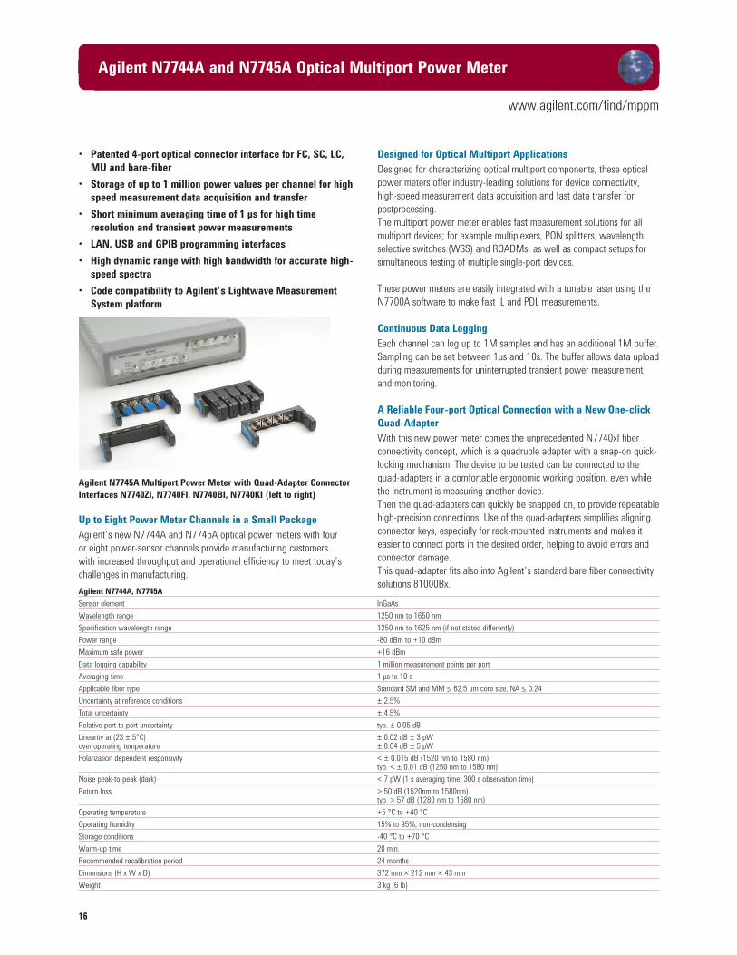
Agilent N7745A Multiport Power Meter with Quad-Adapter Connector
Interfaces N7740ZI, N7740FI, N7740BI, N7740KI (left to right)
Up to Eight Power Meter Channels in a Small Package
Agilent’s new N7744A and N7745A optical power meters with four
or eight power-sensor channels provide manufacturing customers
with increased throughput and operational efficiency to meet today’s
challenges in manufacturing.
Designed for Optical Multiport Applications
Designed for characterizing optical multiport components, these optical
power meters offer industry-leading solutions for device connectivity,
high-speed measurement data acquisition and fast data transfer for
postprocessing.
The multiport power meter enables fast measurement solutions for all
multiport devices; for example multiplexers, PON splitters, wavelength
selective switches (WSS) and ROADMs, as well as compact setups for
simultaneous testing of multiple single-port devices.
These power meters are easily integrated with a tunable laser using the
N7700A software to make fast IL and PDL measurements.
Continuous Data Logging
Each channel can log up to 1M samples and has an additional 1M buffer.
Sampling can be set between 1us and 10s. The buffer allows data upload
during measurements for uninterrupted transient power measurement
and monitoring.
A Reliable Four-port Optical Connection with a New One-click
Quad-Adapter
With this new power meter comes the unprecedented N7740xI fiber
connectivity concept, which is a quadruple adapter with a snap-on quick-
locking mechanism. The device to be tested can be connected to the
quad-adapters in a comfortable ergonomic working position, even while
the instrument is measuring another device.
Then the quad-adapters can quickly be snapped on, to provide repeatable
high-precision connections. Use of the quad-adapters simplifies aligning
connector keys, especially for rack-mounted instruments and makes it
easier to connect ports in the desired order, helping to avoid errors and
connector damage.
This quad-adapter fits also into Agilent’s standard bare fiber connectivity
solutions 81000Bx.
www.agilent.com/find/mppm
Agilent N7744A and N7745A Optical Multiport Power Meter
Agilent N7744A, N7745A
Sensor element InGaAs
Wavelength range 1250 nm to 1650 nm
Specification wavelength range 1250 nm to 1625 nm (if not stated differently)
Power range -80 dBm to +10 dBm
Maximum safe power +16 dBm
Data logging capability 1 million measurement points per port
Averaging time 1 µs to 10 s
Applicable fiber type Standard SM and MM ≤ 62.5 µm core size, NA ≤ 0.24
Uncertainty at reference conditions ± 2.5%
Total uncertainty ± 4.5%
Relative port to port uncertainty typ. ± 0.05 dB
Linearity at (23 ± 5°C) ± 0.02 dB ± 3 pWover operating temperature ± 0.04 dB ± 5 pW
Polarization dependent responsivity < ± 0.015 dB (1520 nm to 1580 nm) typ. < ± 0.01 dB (1250 nm to 1580 nm)
Noise peak-to-peak (dark) < 7 pW (1 s averaging time, 300 s observation time)
Return loss > 50 dB (1520nm to 1580nm) typ. > 57 dB (1280 nm to 1580 nm)
Operating temperature +5 °C to +40 °C
Operating humidity 15% to 95%, non-condensing
Storage conditions -40 °C to +70 °C
Warm-up time 20 min.
Recommended recalibration period 24 months
Dimensions (H x W x D) 372 mm × 212 mm × 43 mm
Weight 3 kg (6 lb)

17
www.agilent.com/find/oct
Agilent 8163xA/B and 8162xB Optical Power Meters
• Complete wavelength range, 450 nm to 1800 nm
• Low uncertainty of ≤ ± 0.8% at reference conditions
• Low PDL of ≤ ± 0.005 dB, for polarization sensitive tests
• High single-sweep dynamic range of 55 dB
• High power measurements of up to +40 dBm
• Support of high channel count testing with dual
power sensor
• Support of bare-fiber and open-beam applications
with a 5 mm detector
• Synchronous measurements with a laser source
or external modulation
Wide Variety of Optical Power Sensors and Optical Heads
The superiority of Agilent’s stimulus-response test solutions
guarantee performance. Agilent has been an industry leader in optical
instrumentation since the early 1980s - excellence in laser sources,
reliable power sensor modules and large detector optical heads.
The power measurement instruments are available in two formats: self-
contained power sensor modules for front-panel optical fiber connection
and external power measurement heads for flexible connection
positioning, which are connected to the mainframe using the 81618A or
81619A (dual) interface modules. The external beams with a large 5 mm
detector are also useful in many free-space optical configurations.
The flexible connector interface system allows the same instrument to be
used with many different types of optical connector.
Logging application for flatness and PDL test
Optical Power Sensors
• 81635A: dual-channel sensor, lowest price
• 81634B: most accurate sensor, highest sensitivity
• 81636B: fast power sensor, 100 k points, 25 μs averaging, higher
dynamic range during logging
• 81630B: highest power sensor
Optical Power Heads
• 81623B: Ge head, general purpose, also specified for 850 nm
• 81624B: InGaAs head, highest accuracy
• 81626B: InGaAs head, high power with high relative accuracy
• 81628B: InGaAs head with integrating sphere, highest power and
accuracy at high power
Passive Component Test
For multi-channel devices, such as, CWDM and AWG, for R&D or the
manufacturing environment, accurate measurements at a minimum cost
are in demand. The modular design provides the user with the flexibility
to add power meters or mainframes for high channel count or high
dynamic range applications. Testing of free space optics, such as, thin
film filter (TFF) and waveguide alignment, are easily supported with the
optical head. Its 5mm detector and long, moveable reach provides the
user with easy handling.
Active Component Test
High power amplifiers and sources are developed today in order to
transmit signals over longer distances and to support a high loss
environment for complex systems. High power measurements of
+40 dBm, can be accomplished without an attenuator, which could
add to the measurement uncertainty.
Optical Component Test in the Visible Wavelength Range
For measuring visible and near-infrared light, like used in POS (polymer
optical fiber) networks, visible LED’s or infrared remote control sources,
the new 81623B Option E01 external power head is an ideal solution.
It covers the wavelength range from 450 nm to 1020 nm.
Research and Calibration
Low measurement uncertainty of < ± 2.5% and low PDL of < ± 0.005
dB
are a couple of the key features found in the Agilent power sensors.
All of Agilent’s power meter products are NIST and PTB traceable to
guarantee precise optical power measurements.
All metrology labs are ISO 17025 certified to meet general requirements
for the competence of testing and calibration laboratories.
The instruments can log up to 20k points with sampling times down to
100µs, or even 100k points at 25µs with the 81636B. These samples
can be triggered by the tunable laser for swept-wavelength spectral
measurements. Built-in routines are also included for measuring
maximum and minimum power, stability over extended time, and offset
from an initial measurement value. Results can be displayed in mW, dBm,
or dB change.

18
www.agilent.com/find/oct
Agilent 8163xA/B and 8162xB Optical Power Meters
Agilent 81635A Agilent 81634B Agilent 81630B
Sensor Element InGaAs (dual) InGaAs InGaAs
Wavelength Range 800 nm to 1650 nm 800 nm to 1700 nm 970 nm to 1650 nm
Power Range –80 dBm to +10 dBm –110 dBm to +10 dBm –70 dBm to +28 dBm
Applicable Fiber Type Standard SM and MM up to 62.5 µm Standard SM and MM up to 100 µm Standard SM and MM up to 100 µm
core size, NA ≤ 0.24 core size, NA ≤ 0.3 core size, NA ≤ 0.3
Uncertainty (accuracy) typ. < ± 3.5 % (800 nm to 1200 nm) ± 2.5 % ± 3.0 % for 1255 nm to 1630 nm
at Reference Conditions ± 3 % (1200 nm to 1630 nm) (1000 nm to 1630 nm) at 980 nm ± 3.5 %
(add ± 0.5% per nm if 980 nm is not the
center wavelength)
at 1060 nm ± 4.0 %
(add ± 0.6% per nm if 1060 nm is not the
center wavelength)
Total Uncertainty typ. ± 5.5% ± 200 pW (800 nm to 1200 nm) ± 4.5% ± 0.5 pW ± 5 % ± 1.2 nW (1255 nm to 1630 nm)
± 5% ± 20 pW (1200 nm to 1630 nm) (1000 nm to 1630 nm) at 980 nm ± 5.5 % ± 1.2 nW
(add ± 0.5% per nm if 980 nm is not
the center wavelength)
at 1060 nm ± 6.0 % ± 1.2 nW
(add ± 0.6 % per nm if 1060 nm is not the
center wavelength)
Relative Uncertainty
– due to polarization typ. < ± 0.015 dB < ± 0.005 dB < ± 0.01 dB
– spectral ripple (due to interference) typ. < ± 0.015 dB < ± 0.005 dB < ± 0.005 dB
Linearity (power) CW –60 dBm to +10 dBm CW –90 dBm to +10 dBm CW –50 dBm to +28 dBm
(970 nm – 1630 nm)
– at 23°C ± 5°C typ. < ± 0.02 dB (800 nm to 1200 nm) < ± 0.015 dB (1000 nm to 1630 nm) ≤ ± 0.05 dB
< ± 0.02 dB (1200 nm to 1630 nm)
– at operating temp. range typ. < ± 0.06 dB (800 nm to 1200 nm) < ± 0.05 dB (1000 nm to 1630 nm) ≤ ± 0.15 dB
< ± 0.06 dB (1200 nm to 1630 nm)
Return Loss > 40 dB > 55 dB > 55 dB
Noise (peak to peak) typ. < 200 pW (800 nm to 1200 nm) < 0.2 pW (1200 nm to 1630 nm) < 1.2 nW (1255 nm – 1630 nm)
< 20 pW (1200 nm to 1630 nm)
Averaging Time (minimal) 100 µs 100 µs 100 µs
Analog Output None included included
Maximum safe input power > +16 dBm +16 dBm 28.5 dBm
Dimensions (H x W x D) 75 mm x 32 mm x 335 mm 75 mm x 32 mm x 335 mm 75 mm x 32 mm x 335 mm
(2.8” x 1.3” x 13.2”) (2.8”x 1.3”x 13.2”) (2.8”x 1.3”x 13.2”)
Weight 0.5 kg 0.5 kg 0.6 kg
Recommended Recalibration Period 2 years 2 years 2 years
Operating Temperature +10 °C to + 40 °C 0 °C to + 45 °C 0 °C to + 35 °C
Humidity Non-condensing Non-condensing Non-condensing
Warm-up Time 20 min 20 min 20 min
Agilent 81636B
Sensor Element InGaAs
Wavelength Range 1250 nm to 1640 nm
Power Range –80 dBm to +10 dBm
Applicable Fiber Type Standard SM and MM up to 62.5 µm core size, NA ≤ 0.24
Uncertainty (accuracy) at Reference Conditions ± 3 % (1260 nm to 1630 nm)
Total Uncertainty ± 5% ± 20 pW (1260 nm to 1630 nm)
Relative Uncertainty
– due to polarization typ. ± 0.015 dB
– spectral ripple (due to interference) typ. ± 0.015 dB
Linearity (power) CW –60 to +10 dBm, (1260 nm to 1630 nm)
– at 23°C ± 5°C < ± 0.02 dB
– at operating temperature range <± 0.06 dB

19
www.agilent.com/find/oct
Agilent 8163xA/B and 8162xB Optical Power Meters (cont.)
Agilent 81636B continued
Return Loss > 40 dB
Noise (peak to peak) < 20 pW (1260 nm to 1630 nm)
Averaging Time (minimal) 25 µs
Dynamic Range at Manual Range Mode– at +10 dBm-range typ. > 55 dB– at 0 dBm-range typ. > 55 dB– at –10 dBm-range typ. > 52 dB– at –20 dBm-range typ. > 45 dB
Noise at Manual Range Mode (peak to peak) CW –60 to +10 dBm, 1260 nm to 1630 nm– at +10 dBm-range < 50 nW– at 0 dBm-range < 5 nW– at –10 dBm-range < 1 nW– at –20 dBm-range < 500 pW
Analog Output Included
Dimensions (H x W x D) 75 mm x 32 mm x 335 mm (2.8” x 1.3” x 13.2”)
Weight 0.5 kg
Recommended Recalibration Period 2 years
Operating Temperature +10 °C to +40 °C
Humidity Non-condensing
Warm-up Time 20 min
Agilent 81623B Agilent 81623B Agilent 81623B Agilent 81623B #E01 Calibration Option C85/C86 Calibration Option C01/C02 (special Silicon Detector)
Applicable Fiber Type Standard Open Beam SM and MM max 100 µm core size, NA 0.3; Parallel beam max ø 4 mm
Sensor Element Ge, ø 5 mm Si, ø 5mm
Wavelength Range 750 nm to 1800 nm 450 nm to 1020 nm
Power Range –80 dBm to +10 dBm -90 dBm to +10 dBm
Uncertainty at Reference Conditions ± 2.2% ± 2.2 % ± 1.7 % ± 2.2% (600 nm to 1020 nm) [1]
(1000 nm to 1650 nm) (1000 nm to 1650 nm) (1000 nm to 1650 nm) ± 3.0 % typ (800 nm to 1000 nm) ±2.5 % (800 nm to 1000 nm) ±3.0 % (800 nm to 1000nm)
Total Uncertainty ± 3.5% ± 100 pW ± 3.5% ± 100 pW ± 3.0% ± 100 pW typ. ± 4% ± 0.5 pW (1000 nm to 1650 nm) (1000 nm to 1650 nm) (1000 nm to 1650 nm) (600 nm to 1020 nm) [2]
± 4.0% typ. ± 250 pW ± 3.5% ± 250 pW ± 4.0% typ. ± 250 pW (800 nm to 1000 nm) (800 nm to 1000 nm) (800 nm to 1000 nm)
Relative Uncertainty– due to polarization < ± 0.01 dB (typ. < ± 0.005 dB)– spectral ripple (due to interference) < ± 0.006 dB (typ. < ± 0.003 dB)
Linearity (power) (CW –60 dBm to +10 dBm) (CW -70 dBm to +3 dBm)– at 23°C ±5°C < ± 0.025 dB typ. ± 0.04 dB ± 0.5 pW– at operating temp. range < ± 0.05 dB typ. ± 0.15 dB ± 0.5 pW
Return Loss > 50 dB, typ. > 55 dB
Noise (peak to peak) < 100 pW (1200 nm to 1630 nm) typ. < 0.5 pW < 400 pW (800 nm to 1200 nm) (700 nm to 900 nm)
Averaging Time (minimal) 100 µs
Analog Output included
Maximum safe input power +16 dBm
Dimensions (H x W x D) 57 mm x 66 mm x 156 mm
Weight 0.5 kg 0.5 kg
Recommended Recalibration Period 2 years 2 years
Operating Temperature 0°C to 40°C 0°C to 40°C
Humidity Non-condensing
Warm-up Time 40 min 20 min
[1] Reference conditions:
• Power level 10 W (-20 dBm), continuous wave (CW)
• Parallel beam, 3 mm spot diameter on the center of the detector
• Ambient temperature 23 °C ± 5 °C
• On day of calibration (add ± 0.3% for aging over one year, add ± 0.6% over two years)
• Spectral width of source < 10 nm (FWHM)
• Wavelength setting at power sensor must correspond to source wavelength ± 0.4 nm
[2] Operating Conditions:
• Parallel beam, 3mm spot diameter on the center of the detector or connectorized fiber with
NA ≤ 0.2 (straight connector)
• Averaging time 1s
• For NA > 0.2: add 1%
• Within one year after calibration, add 0.3% for second year
• Spectral width of source < 10 nm (FWHM)
• Wavelength setting at power sensor must correspond to source wavelength ± 0.4 nm

20
www.agilent.com/find/oct
Agilent 8163xA/B and 8162xB Optical Power Meters (cont.)
Agilent 81624B Agilent 81624B Agilent 81626B Agilent 81626B Calibration Option C01/C02 Calibration Option C01/C02
Sensor Element InGaAs, ø 5 mm InGaAs, ø 5mm
Wavelength Range 800 nm to 1700 nm 850 nm to 1650nm
Power Range –90 dBm to +10 dBm –70 to +27 dBm (1250 nm to 1650 nm) –70 to +23 dBm (850 nm to 1650 nm)
Applicable Fiber Type Standard SM and MM max 100 µm core size, NA ≤ 0.3 Standard SM and MM max 100 µm core size, NA ≤0.3Open Beam Parallel beam max ø 4 mm Parallel beam max ø 4 mm
Uncertainty at Reference Conditions ± 2.2 % ±1.5 % ± 3.0 % ± 2.5 % (1000 nm to 1630 nm) (970 nm to 1630 nm) (950 nm to 1630 nm) (950 nm to 1630 nm)
Total Uncertainty ± 3.5% ± 5 pW ± 2.8% ± 5 pW ± 5.0% ± 500 pW ± 4.5% ± 500 pW, (970 nm to 1630 nm) (950 nm to 1630 nm) (950 to 1630 nm) (1250 to 1630 nm, max 27 dBm)
Relative Uncertainty– due to polarization ≤ ± 0.005 dB (typ. ± 0.002 dB) ≤ ± 0.005 dB (typ. ± 0.002 dB)– spectral ripple (due to interference) ≤ ± 0.005 dB (typ. ≤ ± 0.002 dB) ≤ ± 0.005 dB (typ. < ± 0.002 dB)
Linearity (power) CW –70 dBm to +10 dBm, 1000 nm to 1630 nm CW –50 dBm to +27dBm, 950 nm to 1630 nm– at 23°C ±5°C < ± 0.02 dB < ± 0.04 dB– at operat. temp. range < ± 0.05 dB < ± 0.15 dB
Return Loss typ. 60 dB >45 dB >47 dB
Noise (peak to peak) <5 pW <500 pW
Averaging Time (min.) 100 µs 100 µs
Analog Output included Included
Maximum safe input power +16 dBm +23.5 dBm (850-1250 nm) / +27.5 dBm (1250-1650 nm)
Dimensions (H x W x D) 57 mm x 66 mm x 156 mm 57 mm x 66 mm x 156 mm
Weight 0.5 kg 0.5 kg
Recommended Recalibration Period 2 years 2 years
Operating Temperature 0°C to 40°C 0°C to +35°C
Humidity Non-condensing Non-condensing
Warm-up Time 40 min 40 min
Agilent 81628B with Integrating Sphere
Sensor Element InGaAs
Wavelength Range 800 nm to 1700 nm
Power Range –60 dBm to +40 dBm (800 nm to 1700 nm) For operation higher than 34 dBm 1
Damage Power 40.5 dBm
Applicable Fiber Type / Open Beam Single mode NA ≤ 0.2, Multimode NA ≤ 0.4 / ø ≤ 3 mm center of sphere
Uncertainty at Reference Conditions ± 3.0 % (970 nm to 1630 nm)
Total Uncertainty (970 nm to 1630 nm)
≤10 dBm ± 4.0% ± 5 nW
>10 dBm to ≤20 dBm ± 4.5%
>20 dBm to ≤38 dBm ± 5%
Relative Uncertainty
– due to polarization typ. ≤ ± 0.006 dB
– due to speckle noise at source linewidth:
0.1 to 100 pm typ. < ± 0.02 db
> 100 pm typ. < ± 0.002 db
Linearity (power) (CW –40 dBm to +38 dBm), (970 nm to 1630 nm)
≤ 10 dBm ≤ ± 0.03 dB
> 10 dBm to ≤ 20 dBm ≤ ± 0.06 dB
> 20 dBm to ≤ 37 dBm ≤ ± 0.09 dB
> 37 dBm to ≤ 38 dBm ≤ ± 0.10 dB
at 23 °C ± 5 °C, for operating temperature range add ± 0.03 dB
Return Loss typ. > 75 dB
Noise (peak to peak) < 5 nW
Averaging Time (minimal) 100 µs Analog Output Included
Dimensions (H X W X D) 55 mm x 80 mm x 250 mm Operating Temperature 0 °C to +40 °C
Weight 0.9 kg (without heat sink) Humidity Non-condensing
Recommended Recalibration Period 2 years Warm-up Time 40 min
[1] For optical power higher than 34 dBm the attached heat sink MUST be used! For continuous optical power or average optical power higher than 38 dBm the connector adapters will get
warmer than permitted according to the safety standard IEC 61010-1. The 81628B Optical Head can handle optical power up to 40 dBm, however, operation above 38 dBm is at the operator’s
own risk. Agilent Technologies Deutschland GmbH will not be liable for any damage caused by an operation above 38 dBm.

21
www.agilent.com/find/oct
Agilent 81610A and 81613A Return Loss Modules
81610A 81613A
Source external input only Fabry-Perot Laser (internal)
Output Power — typ. –4 dBm
Center Wavelength — 1310 nm / 1550 nm ± 20 nm typ.
Sensor Element InGaAs InGaAs
Fiber Type Standard single-mode 9 / 125 µm Standard single-mode 9 / 125 µm
External Input max input power: 10 dBm —
min input power: 0 dBm —
damage input power: 16 dBm —
Wavelength Range for External Input 1250 nm to 1640 nm —
Dynamic Range 70 dB 75 dB
Relative Uncertainty of Return Loss (RL) with broadband source with Agilent FP sources User calibration Plug&play
RL ≤ 55 dB < ± 0.25 dB typ. < ± 0.5 dB < ± 0.5 dB (typ. < ± 0.3 dB) typ. < ± 0.6 dB
RL ≤ 60 dB < ± 0.3 dB typ. < ± 1.0 dB < ± 0.6 dB (typ. < ± 0.4 dB) typ. < ± 1.5 dB
RL ≤ 65 dB < ± 0.65 dB typ. < ± 2.0 dB < ± 0.8 dB (typ. < ± 0.5 dB) —
RL ≤ 70 dB < ± 1.7 dB — < ± 1.9 dB (typ. < ± 0.8 dB) —
RL ≤ 75 dB — — typ. < ±2.0 dB —
Total Uncertainty add ± 0.2 dB add typ. ± 0.2 dB add ± 0.2 dB add typ. ± 0.2 dB
Dimensions (H x W x D) 75 mm x 32 mm x 335 mm (2.8” x 1.3” x 13.2”) 75 mm x 32 mm x 335 mm (2.8” x 1.3” x 13.2”)
Weight 0.6 kg 0.6 kg
Recommended Recalibration Period 2 years 2 years
Operating Temperature 10 °C to 40 °C 10 °C to 40 °C
Humidity Non-condensing Non-condensing
Warm-up Time 20 minutes 20 minutes
• Single module for return loss (RL) test
• High dynamic range of 75 dB
• Built-in Fabry-Perot laser source for 1310 nm and 1550 nm
• Use any external laser source, including tunable laser
for swept RL applications
• Three easy calibration steps for enhanced accuracy
Plug&Play for RL Measurement
Portability and cost effective; a single mainframe, single module and
single connection to the device under test are all you need to make
a return loss (RL) measurement. Agilent’s RL test solution solves the
complex operation of calibration and is able to exclude measurement
uncertainties due to coupler / filter usage in your design. In addition,
a built-in FP laser at 1310 nm and 1550 nm enables basic component
tests.
Meeting Manufacturing Needs
The need for IL and RL for optical component tests is fulfilled with the
RL module when used with an optical power meter - preferably an
optical head due to its flexibility. On-board application software supports
step-by-step operation with instructions.
Return Loss Module, Optical Assembly
Swept RL Measurement with Tunable Laser Source
Today’s passive component devices are not only characterized at a single
wavelength, but over a wide wavelength range using a tunable laser
source. The swept wavelength measurement concept is applicable for RL
measurements using an Agilent tunable laser source (TLS) in synchronous
operation of the two modules.

22
www.agilent.com/find/oct
Agilent 8157xA High-Power Optical Attenuators
• Low insertion loss of 0.7 dB
• Excellent wavelength flatness
• Wide wavelength coverage in both single mode
and multi mode fiber
• High attenuation resolution of 0.001 dB
• Active power control option
Modular Design, Fit for Various Component and
Network Solutions
Agilent’s 8157xA variable optical attenuators are a family of plug-in
modules for Agilent’s lightwave solution platform 8163A/B, 8164A/B and
8166A/B. The attenuator modules 81570A, 81571A and 81578A occupy
one slot, while modules 81576A and 81577A occupy two slots. With 17
slots, the Agilent 8166A/B lightwave multichannel system can host up to
17 single slot modules or up to 8 dual slot modules.
Variable Optical Attenuators
The Agilent 81570A, 81571A and 81578A are small, cost effective
attenuator modules with high resolution. They feature excellent wavelength
flatness and can handle high input power levels. Various calibration
features allow the user to set a reference power. Both the attenuation
and the power level, relative to the reference power, can then be set and
displayed in the user interface. An integrated shutter, which can be used
for protection purposes, or to simulate channel drops, is available.
Attenuators for High Optical Input Power
The Agilent modules feature excellent wavelength flatness and
can handle high input power levels of 2 mW. Combined with their
low insertion loss, they are ideal for optical amplifier tests, such as
characterization of EDFAs and of Raman amplifiers, as well as for other
multi-wavelength applications, such as DWDM transmission system test.
Attenuators with Power Control
Agilent’s 81576A and 81577A attenuators feature power control
functionality that allows you to set the output power level of the attenuator.
The attenuator module firmware uses the feedback signal from a photo
diode after a monitor tap, both integrated in the module, to set the
desired power level at the output of the module. When the power control
mode is enabled, the module automatically corrects power changes at
the input to maintain the output level set by the user. After an initial
calibration for the uncertainties at connector interfaces, absolute power
levels can be set with high accuracy. The absolute accuracy of these
power levels depends on the accuracy of the reference power meter used
for calibration.
Transceiver and Receiver Test
Wavelength Flatness
The Agilent optical attenuator modules feature excellent wavelength
flatness and can handle high input power levels. Combined with their
low insertion loss, they are ideal for optical amplifier tests, such as
characterization of EDFAs and of Raman amplifiers, as well as for other
multi-wavelength applications, such as DWDM transmission system test.
One unique feature is a Plug&Play software function which enhances
calibration capacity by setting the integral power of a DWDM signal
with a known spectrum.
Wavelength flatness preserves multichannel signal flatness for EDFA
test.
Modal Fidelity for Multimode Fiber Systems
Signals in multimode fibers are distributed over a range of mode
groups that can have different loss and delay in a link. For dependable
multimode transceiver testing, the instrument used to set the power
level should not change this modal distribution. The bulk-optic filter and
collimated beam path of Agilent multimode attenuators are the best way
to assure homogeneous attenuation of all input modes.

23
www.agilent.com/find/voa
Agilent 8157xA High-Power Optical Attenuators
8157xA 81578A-050 81578A-062
Connectivity Straight (81570A) / Straight (81576A) / Straight flexible connector interface
Angled (81571A) Angled (81577A)
flexible connector interface flexible connector interface
Fibre Type 9 / 125 µm SMF28 9 / 125 µm SMF 50/125 µm MMF 62.5/125 µm MMF
Wavelength Range 1200 to 1700 nm 1250 to 1650 nm 700 nm to 1400 nm
Attenuation Range 0 – 60 dB 0 – 60 dB
Resolution 0.001 dB 0.001 dB
Attenuation Setting Power Setting
Repeatability [1] ± 0.01 dB ± 0.01 dB ± 0.015 dB [2] ± 0.015 dB [13, 15]
Accuracy (uncertainty)[1,3] ± 0.1 dB [4,5] ± 0.1 dB [4, 5] N/A typ. ± 0.15 dB (800 nm to 1350 nm)
± 0.2 dB (at 850 nm ± 15 nm, 1310 nm ± 15 nm)[13, 14]
Settling Time (typical)[23] typ. 100 ms 100 ms 300 ms typ. 100 ms
Transition Speed (typical) 0.1 to 12 dB/s typ. 0.1 to 12 dB/s
Relative Power Meter Uncertainty[16,17] N/A ±0.03 dB ±200 pW [16]
Attenuation Flatness [1,5,7,9] < ± 0.07 dB (typically ± 0.05 dB) for 1520 nm to 1620 nm N/A
typically ± 0.10 dB for 1420 nm to 1640 nm N/A
Spectral Ripple (typical) [8] ± 0.003 dB N/A
Insertion Loss [3,5] Typically 0.7 dB Typically 0.9 dB (excluding connectors) <1.8 dB typ. 1.0 dB (NA = 0.1) typ. 1.0 dB (NA = 0.1)
excluding connectors (typically 1.2 dB) Connectors Including[10,12] typ. 1.3 dB (NA = 0.2) typ. 1.3 dB (NA = 0.2)
< 1.6 dB (typically 1.0 dB) 2.0 dB (NA = 0.2)[13, 15] 2.0 dB (NA = 0.2)[13, 15]
including connectors[10, 13] typ. 3.0 dB (NA = 0.27)
Insertation-Loss Flatness (typical) [1,12,5] ± 0.1 dB for 1420 nm - 1615nm N/A
Polarization-Dependent Loss [3,10,12] < 0.08 dBpp < 0.10 dBpp (typically 0.05 dBpp) N/A
(typically 0.03dBpp)
Return Loss (typical) 45 dB (81570A) / 45 dB (81576A) typ. 27 dB [13, 15]
57 dB (81571A)[10,12] 57 dB (81577A)[10,12]
Maximum Input Power [14] +33 dBm +27 dBm
Shutter Isolation (typical) 100 dB typ. 100 dB
Dimensions (H x W x D) 75 mm x 32mm x 335mm 75 mm x 64mm x 335mm 75 mm x 32 mm x 335 mm
(2.8’’x1.3’’x13.2’’) (2.8’’x2.6’’x13.2’’) (2.8” x 1.3” x 13.2”)
Weight 0.9 kg 1.3 kg 0.9 kg
Recommended Recalibration Period 2 years
Operating Temperature 10 °C to 45 °C
Humidity Non-condensing
Warm-up Time 30 minutes
[1] At constant temperature.
[2] Output power > –40 dBm, input power < +27 dBm. For input power > +27 dBm add typically ± 0.01 dB.
[3] Temperature within 23ºC ± 5ºC.
[4] Input power <+30 dBm; 1550 nm ± 15 nm; typical for 1250 nm < l <1650 nm.
[5] For unpolarized light
[6] Stepsize <1 dB; for full range: typically 6 s.
[7] Relative to reference at 0 dB attenuation.
[8] Linewidth of source ≥ 100 MHz.
[9] For λdisp set to 1550 nm and attenuation <= 20 dB; for higher attenuation add 0.01 dB per additional dB for 1520 to 1620 nm and 0.02 dB/dB for 1450 to 1640 nm.
[10] For 1550 nm ± 15 nm.
[11] Add typically 0.1 dB for 1310 nm ± 15 nm.
[12] Measured with Agilent reference connectors.
[13] Effective spectral source bandwidth > 5nm
[14] For input mode conditions NA = 0.2; for additional ∆NA = 0.01, add ± 0.01 dB typ.
[15] At 850 ± 15 nm or 1310 ± 15 nm
Ordering information
For the most up-to-date information on Agilent optical attenuators, please contact your Agilent Technologies sales representative or visit our web site at: www.agilent.com/comms/lightwave
Connector Interface
All modules require two connector interfaces, 81000xI series (physical contact).

24
www.agilent.com/find/voa
Agilent N775xA, N776xA Multi-Channel Optical Attenuators
N775xA and N776xA Optical Attenuators
• 0.05 dB relative power setting accuracy
• Settling time: 20 ms attenuation, 100 ms power, 200 ms multimode
• Miniature bulk optics for best multimode transfer distribution
• 0.1 to 1000 dB/s or for multimode to 100 dB/s attenuation
transition speed (selectable)
• +23 dBm max. input power
• ≤ 1.2 dB insertion loss
• 45 dB single-mode attenuation range (typ.)
• 35 dB multimode attenuation range
• –50 dBm to +20 dBm power setting range
• Fully compatible with setups and programs developed using the
Agilent 8157x modular attenuators
• Two instrument configurations can be stored and recalled
The Agilent N775xA and N776xA series compact multi- channel at-
tenuators and power meters are a new class of remote controlled fi ber
optic instruments for optical transceiver and network integration test. All
attenuators include an internal power monitor for each channel to reduce
the complexity of closed-loop setups like those needed for very accurate
BER testing or eye mask analysis by allowing power to be set directly
rather than needing to set an attenuation value. All attenuators feature
both attenuation mode and power control mode: In attenuation mode,
the calibrated value of attenuation in dB can be set. The rate of attenu-
ation change during setting can be adjusted between 0.1 and 100 dB/s
for multimode or up to a very fast 1000 dB/s for single mode. In power
control mode, the instrument uses its integrated power monitor to set the
desired power level at the output of the module. It automatically corrects
for input power changes so that the output power level is maintained.
Absolute power levels can be set with high accuracy after an initial offset
calibration.
Modal Fidelity for Multimode Fiber Systems
Signals in multimode fi bers are distributed over a range of mode groups
that can have different loss and delay in a link. For dependable multimode
transceiver testing, the instrument used to set the power level should
not change this modal distribution. The bulk-optic fi lter and collimated
beam path of Agilent multimode attenuators are the best way to assure
homogeneous attenuation of all input modes.
N776xA multi-channel optical attenuators with internal power control
1-channel variable attenuator N7761A
2-channel N7762A SMF attenuator or N7766A MMF attenuator
4-channel N7764A SMF attenuator or N7768A MMF attenuator
N775xA multi-channel optical attenuators with internal power control and
external power meter channels
The 2 integrated power meters in the N7751A and N7752A allow conve-
nient measurement of optical power from different stages of the test setup
and provide a very convenient and automatic way to calibrate the attenu-
ator power reading to the power actually present at another point, such
as the input to the receiver under sensitivity test. This calibration can thus
correct for insertion loss due to switches and other components between
the attenuator and the point of interest.
1-channel attenuator with two power meter channels N7751A
2-channel attenuator with two power meter channels N7752A
NEW

25
www.agilent.com/find/voa
Agilent N775xA, N776xA Multi-Channel Optical Attenuators
Connectivity FC/APC angled (Option -022) or
FC/PC straight (Option -021) contact connector interface
FC/PC straight contact connector interface
Fiber type 9/125 μm SMF 28 50/125 μm (Option 050) or 62.5/125 μm (Option 062) MMF
Wavelength range 1260 nm to 1640 nm 800 nm to 1370 nm
Attenuation range 0 dB to 40 dB (45 dB typ.) 0 dB to 35 dB
Attenuation setting mode Power setting
mode
Attenuation setting mode Power setting mode
Range 0 dB to 40 dB –50 dBm to +20 dBm 0 dB to 35 dB –35 dBm to +20 dBm
Resolution 0.01 dB 0.01 dB 0.03 dB 0.03 dB
Repeatability* typ. ± 0.05 dB for attenuation 0 dB to 30 dB
typ .± 0.10 dB for attenuation 30 dB to 40 dB± 0.025 dB ± 0.05 dB ± 0.05 dB
Accuracy (uncertainty)* typ. ± 0.10 dB for attenuation 0 dB to 10 dB
typ. ± 0.15 dB for attenuation 10 dB to 20 dB
typ. ± 0.40 dB for attenuation 20 dB to 40 dB
typ. ± 0.40 dB
Relative accuracy (uncertainty)* ± 0.05 dB ± 300 pW ± 0.1 dB ± 300 pW
Polarization dependent loss* typ. ≤ 0.15 dBpp for attenuation 0 dB to 10 dB
typ. ≤ 0.25 dBpp for attenuation 10 dB to 20 dB
typ. ≤ 0.5 dBpp for attenuation 20 dB to 40 dB
≤ 0.15 dBpp
Settling time* typ. 20 ms* typ. 100 ms* typ. 200 ms typ. 200 ms
Insertion loss* typ. ≤ 1.2 dB (excluding connectors)
≤ 2.2 dB (including connectors)*
typ. ≤ 1.0 dB (excluding connectors)
≤ 2.0 dB (including connectors)*
Attenuation transition speed selectable from 0.1 to 1000 dB/s selectable from 0.1 to 80 or at > 500
Relative uncertainty of monitor
power meter*
± 0.05 dB ± 300 pW ± 0.1 dB ± 300 pW
Averaging time of monitor power
meter*
2 ms to 1 s 2 ms to 1 s
Return loss* typ. 45 dB typ. 25 dB
Maximum safe input power* +23 dBm +23 dBm
Optical path blocking typ. 45 dB typ. 60 dB
N7751A, N7752A, N7761A, N7762A, N7764A N7766A and N7768A
Sensor element InGaAs
Wavelength range 1260 nm to 1640 nm
Specifi cation wavelength range (1310 ± 15) nm, (1490 ± 10) nm, (1550 ± 15) nm
Power range –80 dBm to +10 dBm
Maximum safe power +16 dBm
Averaging time 2 ms to 1s
Applicable fi ber type Standard SM and MM ≤ 62.5 μm core size, NA ≤ 0.24
Uncertainty at referece conditions* ± 2.5%
Total uncertainty* ± 4.5%
Linearity* at (23 ± 5)°C
Linearity* over operating temperature
± 0.02 dB
± 0.04 dB
Polarization dependent responsivity (PDR) typ. < ± 0.01 dB (1260 nm to 1580 nm)
Spectral ripple (due to interference)* typ. < ± 0.01 dB
Drift (dark)* ± 9 pW
Noise pp (dark)3, (1s averaging time, 300s observation time) < 7 pW*
Return loss* typ. > 57 dB
N7751A and N7752A
NEW

26
www.agilent.com/find/oct
Agilent 81595B Modular Optical Switch
• Excellent repeatability, specified over 10,000 random cycles
• Low insertion loss and polarization dependence
• Single-mode or multimode.
The 1 x 4 optical switch has four positions
Switching Reduces Uncertainty from Connections and Eases
Test Automation
These modular switches can be used to avoid repeated reconnections
during your measurements and are critical to automated procedures.
The low IL and PDL and high repeatability assure minimum impact of the
switch on measurement accuracy.
Switching can be performed from the button on the module, from the
mainframe interface and via GPIB control.
The compact form and high performance allow combining switches for
multistage setups, like five 1x4 modules.
Modal Fidelity for Multimode Fiber Systems
Signals in multimode fibers are distributed over a range of mode
groups that can have different loss and delay in a link. For dependable
multimode transceiver testing, the instrument used to set the power
level should not change this modal distribution. The Agilent multimode
switches are designed with very short collimated paths between fiber,
so signals propagate in practically the same distribution as through
uninterrupted multimode fiber.
Modular Optical Switch Specifications 81595B
Switch Type 1 x 4
Fiber Interface # 009 # 062
single mode multimode
Fiber Type 9/125 µm SMF 62.5/125 µm MMF
Connectivity FC/APC – R key FC/PC straight
Wavelength Range 1270 to 1670 nm 700 to 1400 nm
Insertion Loss (typ.) < 1.25 dB < 1.0 dB
Polarization Dependent Loss typ. 0.07 dBpp N/A
Repeatability* ± 0.03 dB ± 0.03 dB *
Return Loss typ. 55 dB typ. 20 dB
Crosstalk typ. –70 dB typ. –70 dB
Switching Time < 10 ms
Lifetime > 10 million cycles
Maximum Input Power +20 dBm
Dimensions (H x W x D) 75 mm x 32 mm x 335 mm (2.9” x 1.3” x 13.2”)
Weight 0.5 kg
Operating Temperature 10 °C to 45 °C
Storage Temperature* –40 °C to 70 °C
Humidity Non-condensing
Warm-up Time 30 min.

27
www.agilent.com/find/pol
Agilent 8169A Polarization Controllers
• Precise manual and remote adjustments of polarization
state
• Nine Save/Recall registers of SOP
• Continuous auto scanning, tuning the SOP across the entire
Poincare sphere
Developing and manufacturing competitive, high-value components and
systems for today’s optical industries requires precise attention to
polarization sensitivity. The Agilent 8169A polarization controllers can
help by saving time, money and effort when measuring and working with
polarization sensitive devices.
Polarization sensitive devices include EDFAs, single-mode fiber, polarization
maintaining fiber, isolators, switches, lasers, couplers, modulators,
interferometers, retardation plates and polarizers. Device performance
will be affected by polarization-dependent efficiency, loss, gain and
polarization mode dispersion. These polarization phenomena enhance
or degrade performance depending on the application area, be it
communications, sensors, optical computing or material analysis.
An Important Part of a Measurement System
A polarization controller is an important building block of an optical
test system because it enables the creation of all possible states of
polarization. The polarized signal stimulates the test device while the
measurement system receiver monitors the test device’s responses to
changing polarization. Sometimes polarization must be adjusted without
changing the optical power. At other times, polarization must be precisely
synthesized to one state of polarization (SOP) and then adjusted to
another SOP according to a predetermined path.
Characterizing polarization effect of passive optical component
The Agilent 8169A Polarization Controller
The Agilent 8169A provides polarization synthesis relative to a built-
in linear polarizer. The quarter-wave plate and half-wave plate are
individually adjusted to create all possible states of polarization.
Deterministic algorithms within the Agilent 8169A enable the
transition path from one state of polarization on the Poincare sphere to
another to be specified along orthogonal great circles. These features are
important because device response data can be correlated to specific
states of polarization input to the test device. PDL measurement of DWDM
components using the Mueller method is one of the main applications. The
Mueller method stimulates the test path with four precisely known states.
Precise measurement of the corresponding output intensities allows
calculation of the upper row of the Mueller matrix, from which PDL is in
turn calculated. This method is fast, and ideal for swept wavelength
testing of PDL.
Specifications
Specifications describe the instruments’ warranted performance over
the 0° C to +55° C temperature range after a one-hour warm-up period.
Characteristics provide information about non-warranted instrument
performance. Specifications are given in normal type. Characteristics are
stated in italicized type. Spliced fiber pigtail interfaces are assumed for all
cases except where stated otherwise.
Description Agilent 8169A
Operating Wavelength Range 1400 to 1640 nm
Insertion Loss 2,3 < 1.5 dB
Variation over 1 full rotation < ± 0.03 dB
Variation over complete wavelength range < ± 0.1 dB
Polarization Extinction Ratio4 > 45 dB (1530 to 1560 nm)
> 40 dB (1470 to 1570 nm)
> 30 dB (typ.) (1400 to 1640 nm)
Polarization Adjustment
Resolution4 0.18° (360°/2048 encoder positions)
Fast axis alignment accuracy at home position5,6 ± 0.2°
Angular adjustment accuracy: minimum step size ± 0.09°
greater than minimum step size5 < ± 0.5°
Settling time (characteristic) < 200 ms
Memory Save/Recall registers 9
Angular repeatability after Save/Recall5,6 ± 0.09°
Number of scan rate settings 2
Maximum rotation rate6 360°/sec
Maximum Operating Input Power Limitation +23 dBm
Operating Port Return Loss (characteristic)
Total reflection – Individual reflections > 60 dB
Power Requirements 48 to 60 Hz
100/120/220/240 Vrms
45 VA max
Weight 9 kg (20 lb)
Dimensions (H x W x D) 100 mm x 426 mm x 445 mm
3.9 in x 16.8 in x 17.5 in

28
www.agilent.com/find/pol
Agilent N7781B Polarization Analyzer
General Information
The Agilent N7781B is a compact high-speed polarization analyzer which
provides comprehensive capabilities for analyzing polarization properties
of optical signals. This includes representation of the State of Polarization
(SOP) on the Poincaré Sphere (Stokes Parameter). The on-board
algorithms together with the on-board calibration data ensure highly
accurate operation across a broad wavelength range.
Due to its real time measurement capability (1 MSamples/s) the
instrument is well suited for analyzing disturbed and fluctuating signals
as well as for control applications requiring real time feedback of
polarization information.
Analogue data output ports are provided, for example for support of
control loops in automated manufacturing test systems.
Powerful User Interface and remote programming capabilities are
provided by the Polarization Navigator software package of the N7700A
Photonic Application Suite.
Key Features:
• Measurement of Stokes Parameter (SOP)
• Measurement of degree of polarization (DOP)
• High-speed operation (>1 MSamples/s)
• Analog output port for DOP/SOP data
• Robust, no moving parts
Applications
Monitoring / Measurement of
• State of Polarization (SOP)
• Stokes Parameter
• Degree of Polarization (DOP)
• High-Speed Analysis of SOP/DOP of Recirculating Signal
Instrument Setup
Polarization analyzer setup
The instrument setup of the Agilent N7781B/BD polarization analyzer is
shown in the figure above. It consists of a unique polarimeter optics and a
high-speed sampling subsystem. The measurement principle is based on
splitting the light into four sub beams which are filtered through different
polarizers. The resulting four power levels are evaluated using on-board
calibration data to obtain an accurate SOP- and DOP-measurement.
Recirculating Loop Experiments
Managing the polarization properties of the fiber loop is mandatory for
successfully conducting experiments with such structures. The Agilent
N7781B/BD high speed polarization analyzer allows an analysis of the
SOP and the DOP of the circulating signal. The high sampling rate and
the trigger capabilities of the instrument, allow detailed analysis of the
evolution of the SOP and the DOP along each revolution.
Event Trigger Example
Advanced communication systems are sensitive to rapid polarization
changes (“events”) on fiber links. Such events may be caused for
example by trains passing by or by vibrations on bridges. The speed
of the polarization events are of concern for system integrators and
network operators. The event trigger function of Agilent’s N7781B allows
detecting and recording such events.
Tap
couplerTransmitter
Receiver
N7781B/BD
polarization
analyzer
45°
45°
0°
0°
λ/4 Pol.
Optical signal
USB
GPIB
Trigger in / out
4 ch.
ADCDSP &
memory
Ampl
Ampl
Ampl
Ampl

29
www.agilent.com/find/pol
Agilent N7781B Polarization Analyzer (cont.)
Agilent N7781B Polarization Analyzer
Wavelength
Specification Wavelength Range 1270 nm to 1375 nm (Opt 300, O-Band)
1270 nm to 1375 nm, 1460 nm - 1620 nm (Opt 400, O/C/L-Band)
1460 nm to 1620 nm (Opt 500, C/L-Band)
Operating Wavelength Range[2] 1260 nm to 1640 nm
Polarization Analysis
SOP Uncertainty[3],[4] (typical) 1.5°
DOP Uncertainty[3] ± 2.0%
DOP Uncertainty after User Calibration[3], [5] (typical) ± 0.5%
Maximum Sampling Rate up to 1 MHz
Optical Power Measurement
Relative Power Uncertainty[3] C/L-Band: ± 0.03 dB (± 0.02 dB typ.)
O-Band: ± 0.07 dB (± 0.04 dB typ.)
Input Power Range -50 dBm to +7 dBm
Maximum Safe Optical Input Power +12 dBm
[1] Ambient temperature change max. ± 0.5°C since normalization. Specification valid on day of calibration.
[2] SOP/DOP measurements are possible outside the specification wavelength range if a manual user calibration is performed.
[3] Input power > -30 dBm
[4] DOP > 95%
[5] User calibration requires a source with DOP = 100%. User calibration is valid for a fixed wavelength.

30
www.agilent.com/find/pol
Agilent N7782B PER Analyzer and N7783B Thermal Cycling Unit
General Information
Agilent’s N7782B series of PER analyzers has been designed for high
speed and highly accurate testing of the polarization extinction ratio (PER)
in PM fibers. The polarimetric measurement principle guarantees reliable
measurements of PER values of up to 50dB.
The real time measurement capability in combination with automation
interfaces makes this unit ideally suited for integration in manufacturing
systems, for example pig-tailing stations for laser diodes and planar
waveguide components. Analog interfaces are provided for integration of
the system in control loop applications.
Key Benefits
• Accurate PER-measurement up to 50dB
• Real-time display of PER
• Easy-to-use: Reliable results independent of operator skill set
• Swept-wavelength and heating / stretching method
available
• Measurement of the PER versus wavelength
• Fast / slow axis detection
• Instruments available for 1260nm up to 1640nm
• Internal fixed wavelength sources at 850nm / 1310nm /
1550nm available.
Applications
• Laser Diode PMF Pig-tailing Alignment of the PM fiber during the
pig tailing process is supported by real-time display of the PER and
the optical power.
• PMF Splicing In order to support the alignment during the splicing
process of PM fibers the Agilent N7782B provides real time display of
the optical power and of the angular misalignment of the two fibers
• PM component characterization measurement of the PER on PM
components like fiber polarizers, PMF couplers, PMF splitters, etc.
• Characterization of PMF cross-coupling polarization crosstalk in
a PM fiber is measured and displayed as PER
• PM splice characterization The angular misalignment of a PM
splice can be measured in a non-destructive way. Even multiple
splices in a chain can be characterized independently.
Agilent N7782B and N7783B Application Examples
The Wavelength Scanning Method
Using Agilent’s tunable laser source 81600B series in combination with
the Agilent N7782B PER analyzer allows measuring the PER as a function
of wavelength.
The Heating / Stretching Method
The Heating / Stretching method provides accurate measurements of the
PER at a single wavelength.
This method supports in particular well the measurement using narrow-
band laser sources.
An optional internal laser source allows stand-alone operation of the
system.
Agilent’s thermal cycling unit N7783B is fully controlled by the Agilent
N7782B PER analyzer and allows accurate and repeatable cycling of
the temperature of the fiber under test. The PER measurement system
consisting of the Agilent N7782B and the Agilent N7783B shows
excellent accuracy and repeatability. Ease of use and automation
interfaces, such as analog output ports for active alignment, make it
particularly useful for production environments.
Splice Angle Characterization
For characterizing an optical connection between two polarization
maintaining fibers (PMFs), such as an optical splice, two thermal cycling
units (Agilent N7783B) can be used. This eliminates the influence of
input polarization or subsequent fibers at the output and isolates the
angular misalignment of the connection located between the two
thermal cycling units.

31
www.agilent.com/find/pol
Agilent N7782B PER Analyzer and N7783B Thermal Cycling Unit (cont.)
Specifications[1] N7782B PER Analyzer
Wavelength
Specification Wavelength Range 1270 nm to 1375 nm (Opt 300, O-Band)
1270 nm to 1375 nm, 1460 nm - 1620 nm (Opt 400, O/C/L-Band)
1460 nm to 1620 nm (Opt 500, C/L-Band)
Operating Wavelength Range[2] 1260 nm to 1640 nm (Opt 300 / 400 / 500)
PER Analysis
PER Range[3,4] 0 - 50 dB (Opt 300 / 400 / 500)
Optical Power
Input Power Range -50 dBm - +7 dBm (Opt 300 / 400 / 500)
Internal Laser Source
Wavelength Opt. 401 (O-Band): 1290 nm to 1360 nm, 1310 nm typ.
Opt. 501, 401 (C-Band): 1510 nm to 1580 nm, 1550 nm typ.
Output Power[5] (typical) Opt. 401 (O-Band): -12 dBm
Opt. 501, 401 (C-Band): -10 dBm
[1] Ambient temperature change max. ± 0.5°C since normalization. Specification valid on day of calibration.
[2] PER measurements are possible outside the specification wavelength range if the user performs a manual calibration. Note that a fully polarized light source is needed for calibration.
[3] Input power > -30 dBm
[4] Narrow-band light source with DOP > 95% needed.
[5] At room temperature.
Agilent N7783B Thermal Cycling Unit Characteristics
Fiber jacket diameter up to 3 mm
Ambient Temperature Range 20 °C - 30 °C
Minimum Peak-to-Peak Temperature Tuning Range 50K
Power 100 - 240 VAC, < 36W
Dimensions (H x W x D) 64 mm x 160 mm x 61 mm

32
www.agilent.com/find/pol
Agilent N7784B, N7785B, N7786B Polarization Controllers
Agilent offers a wide range of instruments that control the state of
polarization (SOP) of an optical signal for various applications. Some
measurements should confirm that the performance of an optical
component does not exceed acceptable dependence on polarization,
such as tests for polarization dependent loss (PDL) and polarization mode
dispersion (PMD). In other cases, a signal with specific polarization
should be tested.
Agilent N7784B, N7785B, and N7786B
These 3 instruments are all based on high-speed solid state optics to
rapidly switch the polarization of an incoming signal. They are used
with polarized input signals from lasers and can adjust, scan or align
the output state of polarization. The instruments are controlled from an
external PC and convenient graphical user interface control is provided
with the included Polarization Navigator software, distributed with the
N7700A Photonic Application Suite. Automated control is provided by the
GPIB and USB interfaces.
N7785B Synchronous Scrambler
The N7785B Synchronous Scrambler provides fast SOP switching in
response to internal or external triggering. This supports optical network
simulations that often require switching of the signal SOP in a random
way within a few microseconds, such as in recirculating loop tests. The
SOP is switched rapidly, and then held for a predefined time until it again
switches to a new SOP. The output SOP is controlled but not determined
by the N7785B and will be changed if the input SOP changes. The output
SOP can be adjusted to a desired external condition, such as maximizing
the signal through a polarizer.
Application routines in the Polarization Navigator software can be used
for random scrambling and continuous scrambling (where the state of
polarization moves smoothly about the Poincaré sphere, similar to a
flipper-style scrambler) over a wide range of speeds.
N7784B Polarization Controller
The N7784B Polarization Controller provides alignment and fast
stabilization of SOP into polarization maintaining fiber (PMF) or with
respect to an external condition by adding an analog feedback and
polarizer path to the basic N7785B configuration.
For alignment into PMF, the input signal is first routed through the fast
switching controller with single-mode fiber (SMF) and is available at
an intermediate front panel output. An external jumper fiber is used to
route the signal into the polarizer path consisting of a polarizing beam
splitter with one output monitored by a photodetector. The other output
is coupled to the front panel output with PMF. The signal from the
photodetector is used to actively align and stabilize the input signal into
the PMF output that could then be connected to a modulator or other
polarization dependent device.
Similarly, the signal can be used directly from the intermediate output
and a user-configured setup can provide the feedback for optimizing the
desired SOP from the instrument.
N7786B Polarization Synthesizer
The N7786B Polarization Synthesizer includes internal SOP monitoring
and feedback via a tap coupler to determinately set and hold any chosen
states or sequences of polarization. This allows generation of sequences
with chosen relative SOP orientation. This is often used for component
analysis based on Mueller Matrix or Jones Matrix analysis. The uniquely
fast switching supports the new single-sweep spectral PDL measurements
with the N7700A software, which eliminates sensitivity to environmental
stability and minimizes measurement time. Analysis of these results into
transmission spectra of the primary device axes (like TE and TM) is also
achieved in this way. The real-time monitoring and logging of output SOP
permits accurate calculation including the wavelength dependence of the
SOP.
The real-time monitoring and feedback also are used in this instrument to
provide stabilized SOP, even with fluctuation and drift of the input SOP.
The output SOP can be defined in following ways:
• Set-and-forget: When the front panel button is pushed, the
current SOP is stored and maintained, even if polarization changes
occur at the instrument input
• Defined Stokes: The target output SOP can be defined by the user
using the Stokes parameters
The Polarization Navigator also has a convenient button to quickly change
from a manually adjusted SOP to the corresponding orthogonal state, as
can be used to check extinction ratio.
N7786B
N7785B
N7784B

33
www.agilent.com/find/pol
Agilent N7784B, N7785B, N7786B Polarization Controllers
Specifications[1] N7784B Polarization Controller
Wavelength
Operating Wavelength Range 1260 to 1640 nm
Wavelength Range in Stabilizer Mode[2] 1520 to 1580 nm
Polarization Control and Stabilization
SOP Switching Time (open-loop) < 10 µs
PER at PMF Output (typical) > 23 dB
Stabilizer Response Time[3] (typical) 2 ms
Optical Power
Insertion Loss Port I –> Port II[4] < 3.5 dB (< 3.0 dB, typ.)
Insertion Loss Port III –> Port IV[5] < 1.8 dB (< 1.4 dB, typ.)
PDL Port I –> Port II (typical) < 0.2 dB (C/L - Band)
Maximum Safe Input Power Port I: 20 dBm Port III: 3 dBm
Input Power Range in Stabilizer Mode Port III: -30 dBm to 0 dBm
[1] Ambient temperature change max. ± 0.5°C since normalization. Specification valid on day of calibration;
[2] Outside the stabilizer wavelength range, the PER at PMF Output may be degraded;
[3] Input power at Port III > -30 dBm, response to an immediate step of 180° on the Poincaré sphere;
[4] For SOP scrambling/switching, only ports I/II are used;
[5] Valid for optimum input polarization at PBS input (Port III). Add insertion loss of port I/II and III/IV to obtain total insertion loss for SOP stabilizing mode.
Specifications[1] N7785B Synchronous Scrambler
Wavelength
Operating Wavelength Range 1260 to 1640 nm
Polarization Control
SOP Switching Time < 10 µs
Optical Power
Insertion Loss < 3.5 dB (< 3.0 dB, typ.)
PDL (typical) < 0.2 dB (C/L - Band)
Maximum Safe Input Power 20 dBm
[1] Ambient temperature change max. ± 0.5°C since normalization. Specification valid on day of calibration.
Specifications[1] N7786B Polarization Synthesizer
Wavelength
Specification Wavelength Range 1270 to 1375 nm, 1460 to 1620 nm (Opt 400, O/C/L-Band) 1460 to 1620 nm (Opt 500, C/L-Band)
Operating Wavelength Range[2] 1260 to 1640 nm
Polarization Control and Stabilization
SOP Switching Time (non deterministic) < 10 µs
SOP Cycling Time[6] < 25 µs
Remaining SOP Error after deterministic SOP setting (typical)[7] < 3° at input SOP movement rate of 1.2 rad/s < 6.5° at input SOP movement rate of 40 rad/s
Polarization Analysis[7]
SOP Uncertainty[3],[4] 1.5°
DOP Uncertainty[3] ± 2.0%
DOP Uncertainty after User[3], [5] Calibration (typical) ± 0.5%
Optical Power Measurement[7]
Relative Power Uncertainty[3] C/L-Band: ± 0.14 dB (± 0.12 dB typ.)
O-Band: ± 0.16 dB (± 0.14 dB typ.)
Input Power Range -38 dBm to +19 dBm
Optical Power
Insertion Loss < 4.0 dB (< 3.5 dB, typ.)
PDL (typical) < 0.2 dB (C/L - Band)
Maximum Safe Input Power 20 dBm
[1] Ambient temperature change max. ± 0.5°C since normalization. Specification valid on day of calibration; [2] SOP/DOP measurements are possible outside the specification wavelength range if
the user performs a manual calibration; [3] Input power > -20 dBm; [d] DOP > 95%; [4] User calibration requires a source with a known DOP; [5] The instrument adaptively finds the polarization
controller settings to let the SOP cycle through user-defined polarization states (closed loop operation). After having found these settings, the SOP can cycle through the polarization states in open
loop operation; [6] This value is defined to be 5 times the standard deviation of the angular SOP error on the Poincaré sphere. Valid if controller is turned on. Power at instrument input > -10 dBm;
[7] The polarization analyzer readout reflects the SOP at the instrument output. Thus, effects caused by the internal polarization controller are included.

34
www.agilent.com/find/pol
Agilent N7788B/BD Optical Component Analyzer
N7788BD Bench-top Mainframe with built-in PC
N7788B Bench-top Mainframe
General Information
Agilent Technologies pushes the limits of component measurements
with the N7788B and N7788BD Component Analyzer. Its proprietary
technology is comparable with the well-known Jones-Matrix-
Eigenanalysis (JME) which is the standard method for measuring
Polarization Mode Dispersion (PMD) or differential group delay (DGD) of
optical devices.
Compared to the JME, Agilent’s new single scan technology offers a
range of advantages:
A complete set of parameters:
• DGD/ PMD / PDL / 2nd order PMD
• Power / Loss
• TE / TM-Loss
• Principal States of Polarization (PSPs)
• Jones and Mueller Matrices
For measuring these parameters, the N7788B/BD is used together with
an Agilent continuous-sweep tunable laser like the 81600B, and control
is provided with the Polarization Navigator package of the N7700A
Photonic Application Suite.
The N7788B/BD also provide the full polarization analysis functionality of
the N7781B.
Key Benefits
Highest Accuracy in a single sweep: no averaging over multiple sweeps
required
High Measurement Speed:
Complete measurement across C/L-band in less than 10 seconds (no need
to wait for many averages)
Robustness against fiber movement / vibration and drift:
Fixing fibers with sticky tape on the table or even operation on isolated
optical table is not required!
No limitation on optical path length of component
The internal referencing scheme guarantees reliable and accurate
measurements.
Applications
• Fiber characterization: SMF, PMF, DCF
• Passive component testing: filters, isolators, circulators
• Dynamic component / module testing: OADM / ROADM
• Active component testing: EDFAs, SOAs, VOAs
• Link test: In-Channel measurements across amplifiers
Designed for the Manufacturing Floor
High Throughput:
A complete analysis across the C and the L band is performed in less than
10 seconds!
Software Drivers:
A range of software drivers is available for external control of the system.
This allows easy integration in common ERP systems.
Remote Control:
Control of the instrument through LAN or via the Internet is supported.
This supports automation as well as trouble shooting.
Report Generation:
Generating PDF reports is supported. The content including layout is
configurable by the user.
Real-time Power Readout:
High throughput measurement of non-connectorized components is
supported by providing a real time power readout which enables fiber
coupling of the new device
Barcode Scanner:
Using Barcode scanner is supported for quick transfer of the DUT serial
number
Instrument Setup and Application Examples
The instrument setup is shown in the figure above. A Lithium-Niobate
polarization controller determines the input polarization to the DUT.
While the tunable laser source1 is sweeping over the desired wavelength
range, a polarimeter analyzes the output state of polarization while input
polarization is being modified. The result will be a highly accurate device
characterization with respect to DGD/PDL/Loss etc. Furthermore, the
internal optical switch provides continuous self calibration for excellent
repeatability.
Resolving TE/TM Insertion Loss
The TE/TM-function allows accurate determination of the minimum and
maximum loss of the DUT at each wavelength.
Due to birefringence, optical filters tend to show different transmission
functions depending on the polarization state.
(1) not included
Laser in
SMFPMF
USB
Polarimeter
GPIB
LiNbO3 polarization controller
Trigger in
Trigger outPower In
DUT
Microcontroller board

35
Excellent Spectral Resolution
Due to the excellent spectral resolution with the 81600B TLS, the Agilent
N7788B/BD is best suited for intra-channel DGD/PDL characterization.
The All-Parameter-JME algorithm allows flexible adjustments of the
wavelength resolution without the need to repeat the measurement. This
simplifies finding the optimum trade-off between PDL/DGD accuracy and
wavelength resolution.
Long Term Measurements
The capability of performing quick PMD-measurements makes this
measurement system well-suited for collecting long-term PMD data. The
PC software allows to continuously collect the spectral PMD data and
store it on the hard disc. The data can then be visualized as pseudo-color
plot (see figure).
Specifications[1] N7788B/BD Optical Component Analyzer
Wavelength
Specification Wavelength Range 1270 to 1375 nm (Opt 300, O-Band)
1270 to 1375 nm, 1460 nm to 1620 nm (Opt 400, O/C/L-Band)
1460 to 1620 nm (Opt 500, C/L-Band)
Operating Wavelength Range[2] 1260 nm to 1640 nm
Differential Delay
DGD Uncertainty[3] Resolution 2,0 nm: ± (30 fs + 0,3% × DGD)
Resolution 0,1 nm: ± (30 fs + 3,0% × DGD)
DGD Measurement Range[3] 0 … 1000 ps
PMD Uncertainty[4] ± (30 fs + 2,0% × PMD)
PMD Repeatability (typical) ± 3 fs
PMD Measurement Range[4] 0 - 300 ps
Loss
PDL Uncertainty[5] C/L-Band: ± (0.05 dB + 4% × PDL)
O-Band: ± (0.10 dB + 4% × PDL)
PDL Repeatability (typical) ± 0.05 dB
Insertion Loss Uncertainty (typical)[3] C/L-Band: ± 0.03 dB
O-Band: ± 0.07 dB
Insertion Loss Dynamic Range (typical)[3] > 41 dB (for TLS power levels higher than -6 dBm, increase value accordingly)
Polarization Analysis
See N7781B Specifications
Optical Power Measurement
See N7781B Specifications
[1] Ambient temperature change max. ± 0.5°C since normalization. Valid for 81600B tunable laser source family. Tunable laser power set to -6 dBm. Sweep over specification wavelength
range. Specification does not include instability in test device. Specified loss ranges include loss of test device and any additional switches or connections in the optical path.
Specification valid on day of calibration.
[2] Only SOP/DOP measurements are possible outside the specification wavelength range if the user performs a manual calibration.
[3] DUT properties: Insertion Loss < 30 dB, PDL < 1 dB, DGD < 150 ps. Specification is typical for DGD > 150 ps.
[4] DUT properties: Insertion Loss < 41 dB, PDL < 3 dB, PMD < 50 ps. Applies for highly mode-coupled devices such as single mode fibers. Specification applies for PMD being the
averaged DGD over a wavelength span of 100 nm. Specification is typical for PMD > 50 ps.
[5] DUT properties: Insertion Loss < 25 dB, PDL < 6 dB. Note: DUT connectors are considered being part of the DUT. Thus, angled connectors will add to the device PDL.
DGD
Wavelength
DG
D
Wavelength
Tim
e
DGD
www.agilent.com/find/pol
Agilent N7788B/BD Optical Component Analyzer (cont.)

36
www.agilent.com/find/pol
86038B Photonic Dispersion and Loss Analyzer
• Fastest measurement speed for manufacturing test
• Highest CD and PMD accuracy and resolution for
manufacturing and R&D • Specified operation over 1260 to
1640 nm (O-L band)
• 2nd-order PMD, GD-ripple and other analysis functions
• Expandable for enhanced PDL accuracy and multiport use
• Industry-standard measurements with the modulation phase
shift method for measurements to any length
The Agilent 86038B continues Agilent’s tradition in measuring chromatic
dispersion with this instrument for full dispersion and insertion loss
analysis in fast swept-wavelength measurements with polarization
resolution. It simultaneously measures chromatic dispersion (CD) and
group delay, polarization mode dispersion (PMD) and DGD, insertion loss
(IL), and polarization dependent loss (PDL) and optical length and phase.
An advanced implementation of the industry standard modulation phase
shift method (MPS) provides fast CD and GD traces with high selectable
wavelength resolution and low noise without repeated averaging. Use of
the polarization resolved MPS method with a wide range of modulation
frequency allows measurements to any device length and to highest
resolution.
The 86038B uses the industry standard Modulation Phase Shift (MPS)
method for both GD/CD and DGD measurements. The advanced
implementation of the MPS method delivers both high GD and
wavelength resolution. The basic method is standardized in IEC 60793-
1-42. The method is documented for DGD and PMD in other standards
such as IEC 61280-4-4. This is the one method that can determine a
DGD value from measurements only at that wavelength, allowing high
resolution with low noise.
The 86038B uses fast swept measurements that are ideal for
manufacturing. On the manufacturing floor, success depends on high
volume throughput, fast ramp-up and reduced cost of test. Trust in your
results is vital. The MPS method used on the 86038B avoids sensitivity to
thermal drifts and mechanical vibrations. And the Drift Correction feature
assists in obtaining repeatable and stable measurements even in an
unstable environment.
Key Capabilities
Simultaneous GD, CD, DGD, PMD, IL, and PDL spectra with a single
connection and a single setup reduce test time, instrument footprint and
measurement uncertainty.
CD uncertainty: ± 0.07 ps/nm; ± 0.3% CD
Zero dispersion wavelength uncertainty: ± 0.015nm
Group delay repeatability: < ± 0.03 ps (< ± 30 fs)
PMD uncertainty: ± 0.07 ps
Differential group delay uncertainty: ± 100 fs
Enhanced PDL and insertion loss accuracy: PDL < 0.05 dB,
Loss < 0.02 dB
High speed swept measurements: DGD measurements over
100nm can be obtained in less than 30 seconds.
GD/CD measurements automatically corrected for PMD
Allows very accurate CD measurements
6 polarization-state measurements
This selectable method adds additional accuracy to polarization
measurements, especially over wide wavelength ranges
Up to 4-port component testing:
Agilent’s 81595B Modular Optical Switch allows testing of up 4 ports of
a multichannel DUT.
Wide dynamic range: > 40 dB
Flexible choice of wavelength range:
from 1260 nm to 1640 nm
Supports multiple wavelength band operation
by controlling up to 4 tunable lasers. Automatic laser
switching is available on request.
Drift correction:
Provides excellent stability and accuracy when the environmental
conditions of the room or the test device are gradually changing.
Selectable and high wavelength resolution:
Resolution to < 0.2 pm for challenges like GD ripple characterization
and up to 2.5 GHz MPS modulation frequency for lowest noise fiber
characterization.
Powerful remote control:
Write your own applications for enhanced measurement
control and analysis
Fast and accurate length measurement
In a few seconds, the fiber or device length can be determined, short
or long. The measurement, according to the standard IEC 60793-1-22
and using the modulation frequency range of the 86038B supports
determination of CD and PMD coefficients of fiber, the dependence of
dispersion on length. The short length accuracy of 0.02 mm corresponds
to absolute delay measurements with 100fs accuracy.
37
www.agilent.com/find/pol
Agilent 86038B Photonic Dispersion and Loss Analyzer (cont.)
Specifications (condensed: full details in 86038B Data Sheet)
(swept wavelength mode; ambient temperature change < ±0.5°C since normalization; TLS power, 0 dBm; sweep over specified wavelength range)
Group Delay and Differential Group Delay Measurement(modulation frequency, 2 GHz; IF bandwidth, 70Hz; wavelength increment, 1nm; PDA correction)
Accessories
86038B - 505 81595B 1 x 4 Modular Optical Switch for 4 Port Operation
86038B - 510 Verification Fiber
86038B - 520 Spare Hard Drive
For device insertion loss <_ 4 dB <_ 10 dB <_ 20 dB typ. <_ 30 dB typ.
Relative GD Uncertainty ± 50 fs ± 100 fs ± 350 fs ± 4 ps
Relative GD Repeatability ± 30 fs ± 50 fs ± 300 fs ± 3.5 ps
DGD Uncertainty ± 100 fs ± ± 150 fs ± ± 500 fs ± ± 5 ps ±
2.5% of DGD 3% of DGD 2% of DGD 12% of DGD
DGD Repeatability ± 50 fs ± ± 100 fs ± ± 350 fs ± ± 3.5 ps ±
1% of DGD 2% of DGD 1.5% of DGD 12% of DGD
PMD Uncertainty (typ., av. over 100 nm Range) ±70 fs ± ± 100 fs ± ± 300 fs ± ± 3 ps ±
2% of PMD 2% of PMD 2% of PMD 4% of PMD
CD Uncertainty (ps/nm) ± (0.07 + ± (0.14 + ± (0.5 + ± (6 +
at 1 nm wavelength resolution 0.3% of CD) 0.3% of CD) 0.3% of CD) 0.3% of CD)
Zero-dispersion wavelength uncertainty ± 0.015 nm ± 0.022 nm ± 0.058 nm ± 0.6 nm
for a fiber with 1 ps/nm2 l-slope (derived from specification)
Modulation Frequency Settable: 5 MHz to 2.5 GHz
Length Uncertainty ± (0.02 mm + 0.00001 of length, (typ., specification valid for <_ 50 km)
PDL uncertainty Without Option 400: ± (0.15 dB + 3% of PDL) typ.
With Option 400: ± (0.05 dB + 3% of PDL): loss 0-4 dB.
Gain/Loss Uncertainty Without Option 400: ± (0.1 dB + 5% of PDL) typ.
With Option 400: ± 0.02 dB, loss <_ 10dB; ± 0.04 dB, loss <_ 30 dB;
Dynamic Range > 40 dB, typical
Wavelength Range Full Range (nm) Range of Specifications (nm)
Option #120 or 320 1440 to 1640 1475 to 1625
Option #116 or 316 1495 to 1640 1510 to 1620
Option #115 or 315 1450 to 1590 1480 to 1580
Option #114 or 314 1370 to 1495 1420 to 1490
Option #113 or 313 1260 to 1375 1270 to 1350
Abs. wavelength uncertainty With Option 410: ± 4 pm typ. / ± 2 pm typ.
(swept/stepped mode) Without Option 410: ± 6.1 pm typ. /± 10pm, ± 3.6 pm typ.
Rel. wavelength uncertainty ± 4 pm typ. / ± 5 pm, ± 2 pm typ.
(swept/stepped mode)
Assembled dimensions (HxWxD) 555 mm x 435mmm x 555 mm
(single TLS configuration) 54 kg (120 lb).
Performance Options 86038B - 400 Enhanced PDL and Loss Accuracy
86038B - 410 Add 86122A multi-wavelength meter for ±1.0 pm accuracy

38
Accessories
81000HI - E-2000 Connector Interface
For physical contact connections
Recommended for angled and straight connector
interfaces. Use with sources. Not for sensors.
81000LI - LC/F3000 Connector Interface
For physical contact connections
Recommended for angled and straight connector
interfaces. Use with sources.
81000FI - FC/PC Connector Interface
N-keying (key slot = 2.20mm nominal)
For physical and non-physical contact connections
Recommended for angled and straight connector
interfaces
81000MI - MU Connector Interface
For physical contact connections
Recommended for angled and straight connector
interfaces. Use with sources.
81000KI - SC Connector Interface
For physical and non-physical contact connections
Recommended for angled and straight connector
interfaces
81000SI - DIN 4108/47256 Connector Interface
For physical and non-physical contact connections
Recommended for angled and straight connector
interfaces
A gold-plated HMS-10 connector for use in measuring return loss of
optical connectors. It allows you to establish a precise reference for
reflection measurements. Return loss is 0.18 dB ± 0.1dB (96% ± 2%)
81000PI - E-2000 Connector Interface
For non-physical contact connections
Recommended for angled and straight connector
interfaces. Use with sensors.
81002LI - LC/F3000 Connector Interface
For non-physical contact connections
Recommended for angled and straight connector
interfaces. Use with sensors.
81000NI - FC/APC Connector Interface
R-keying (key slot = 2.00mm nominal)
For physical and non-physical contact connections
Recommended for angled and straight connector
interfaces
81002MI - MU Connector Interface
For non-physical contact connections
Recommended for angled and straight connector
interfaces. Use with sensors.
81000VI - ST Connector Interface
For physical and non-physical contact connections
Recommended for angled and straight connector
interfaces
81000UM - Universal Feedthrough Adapter
To adapt 81000BR or HMS-10 connectors to any other
appropriate connector. In combination with an Agilent
81000xI connector interface, this adapter allows you
to mate an HMS-10 connector to another HMS-10,
FC/PC/SPC, APC, DIN, ST, E-2000, or SC connector.
It can also be used to mate an Agilent 81000BR reference reflector to a
connector under test. The Agilent 81000UM is a through adapter only. It
can not be used at the fiber interfaces of the modules.
81000BR - HMS-10 Reference Reflector
• Return Loss = 0.18 dB ± 0.1 dB (96% ± 2%) typ.
• Wavelength range: 1200 nm to 1600 nm
81000RI - High Return Loss Interface
• Return Loss = 36 dB typ.
• To adapt straight connectors to Power Sensor
modules

39
Accessories
Threaded Head Adapter
(Threaded adapter for 8152x Optical Heads, 8162x Optical Heads
with 81624DD and 81628B Optical Heads)
Bare Fiber Adapters and Interfaces
The Agilent Bare Fiber Connectivity Solutions enable the easy and
repeatable adaptation of optical components to Agilent’s standard
optical heads (all 8152x and 8162x series) and sensor modules
81630B, 81634B.
81000BC Bare Fiber Connectivity Set for 81623B,
81624B and 81626B (1x head Adapter,
1x 0-400 um holder, 1x 400-900 um holder,
1x gauge)
81000BI Bare Fiber Connectivity Set for 81630B
and 81634B (1x sensor adapter, 1x 0-400
um holder, 1x 400-900 um holder, 1x
gauge)
81000BT Bare FC Set for 8152x and 8162x Optical
Heads and threaded interface
81004BH Bare Fiber Holder Set (10x 0-400 um
holder)
81009BH Bare Fiber Holder Set (10x 400-900 um
holder)
81004BM / 9BM Bare Fiber Holder Set (4x 0-400 um or 0-900
um holder)
Optical Head Adapter
These adapters are to be used with Agilent optical heads only. The
connector adapters are needed to attach connecterized fibers.
Optical Head Adapters – with integral D-shape attachment for
8162xx optical head (except 81628B – see threaded version)
81003TD - MPO/MTP Connector Adapter
Optical head adapter with integral D-shape attachment
for 8162xx optical head (except 81628B) for connection
of ribbon cables with MT/MPO connectors. The adapter
has connector guide pins and should be used with
female cable connectors.
81001ZA - Blank Adapter
Plug-in D-shape adapter for 8162x Optical Heads To be
customized by customer
Doesn’t match to 8152x and High Power Optical Heads
81624DD - D-shape Adapter
To connect threaded adapters to 8162x D-shape
receptable. Included with new heads except 81628B.
Remove for using head with D-shaped adapters.
81000FA
FC/PC
FC/APC
81000KA
SC
81000PA
E-2000
81000VA
ST
81003LA
LC/F3000
N7740KI - SC
4-port SC connector for the multiport power
meter series N7744A and N7745A.
N7740FI - FC
N7740BI - Bare Fiber Adapter
Fiber holders not included; please add
81004BM or 81009BM
N7740ZI - Zeroing Adapter
N7740LI - LC
4-port LC connector for the multiport power
meter series N7744A and N7745A.
N7740MI - MU
4-port MU connector for the multiport
power meter series N7744A and N7745A
81001FA
FC/PC
81001KA
SC
81001PA
E-2000
81001LA
LC/F3000
81001MA
MU

Agilent Email Updates
www.agilent.com/find/emailupdates
Get the latest information on the
products and applications you select.
www.lxistandard.org
LAN eXtensions for Instruments puts
the power of Ethernet and the Web
inside your test systems. Agilent is a
founding member of the LXI consor-
tium.
Agilent Channel Partners
www.agilent.com/find/channelpartners
Get the best of both worlds: Agilent’s
measurement expertise and product
breadth, combined with channel
partner convenience.
For more information on Agilent Tech-nologies’ products, applications or services, please contact your local Agilent office. The
complete list is available at:
www.agilent.com/fi nd/contactus
AmericasCanada (877) 894 4414 Brazil (11) 4197 3500Mexico 01800 5064 800 United States (800) 829 4444
Asia Pacifi cAustralia 1 800 629 485China 800 810 0189Hong Kong 800 938 693India 1 800 112 929Japan 0120 (421) 345Korea 080 769 0800Malaysia 1 800 888 848Singapore 1 800 375 8100Taiwan 0800 047 866Other AP Countries (65) 375 8100
Europe & Middle EastBelgium 32 (0) 2 404 93 40 Denmark 45 70 13 15 15Finland 358 (0) 10 855 2100France 0825 010 700* *0.125 €/minute
Germany 49 (0) 7031 464 6333 Ireland 1890 924 204Israel 972-3-9288-504/544Italy 39 02 92 60 8484Netherlands 31 (0) 20 547 2111Spain 34 (91) 631 3300Sweden 0200-88 22 55United Kingdom 44 (0) 118 9276201
For other unlisted Countries: www.agilent.com/fi nd/contactusRevised: October 14, 2010
Product specifications and descriptions in this document subject to change without notice.
© Agilent Technologies, Inc. 2010Printed in USA, Nov. 1, 20105989-6753EN
www.agilent.comwww.agilent.com/find/lightwave
Agilent Advantage Services is committed to
your success throughout your equipment’s
lifetime. We share measurement and service
expertise to help you create the products that
change our world. To keep you competitive,
we continually invest in tools and processes
that speed up calibration and repair, reduce
your cost of ownership, and move us ahead of
your development curve.
www.agilent.com/quality
www.agilent.com/find/advantageservices
www.axiestandard.org AdvancedT-
CA® Extensions for Instrumentation
and Test (AXIe) is
an open standard that extends the
AdvancedTCA® for general purpose
and semiconductor test. Agilent
is a founding member of the AXIe
consortium.
http://www.pxisa.org
PCI eXtensions for Instrumentation
(PXI) modular instrumentation
delivers a rugged, PC-based high-per-
formance measurement and automa-
tion system.
TM
Related Literature:
Lightwave Catalog Volume 2:
Transceiver Test 5989-6754EN