emotion system – technical specificationsrvweb01.softeco.it/emotion/portals/_rainbow... · draft...
TRANSCRIPT
Deliverable No.: D 6
eMOTION System – Technical Specification
March 2008
Final 1.0
Project funded by the European Community under the Sixth Frame-work Programme for Research and Technological Development.
Deliverable D 6 eMOTION System – Technical Specification
© eMOTION Consortium Page 2 of 90
Project ref. no.: TREN/06/FP6TR/S07.57248/019939 EMOTION
Project title: eMOTION – Europe-wide multi-Modal On-trip Traffic Informa-tiON
Deliverable title: eMOTION System –Technical Specification
Deliverable number: D 6
Deliverable status: Public
Number of pages: 90
Author(s): Reinhard Erstling (interactive instruments – editor) Stefan Olk (interactive instruments – editor) Marco Garrè (Azienda Mobilità e Infrastrutture) Karl Schedler (micKS) Daniel Heckert (Momatec) Andreas Kochs (Momatec) Martin Eitzenberger (OneStepAhead) Michele Masnata (Softeco) Grant MacKinnon (Transport Simulation Systems)
Status Version Date Change Note ID
Draft 0.1 31.07.2007 Document initialisation
Draft 0.2 12.10.2007 Consolidated task assignments
Draft 0.3 28.10.2007 4.5 Information Mapping dropped;
4.4.1 Visualisation and Mapping: main part of definitions moved to newly created Appendix 3.
First input to 6 Engineering Viewpoint (6.2 Distribution of Nodes): DRM Component Model
Draft 0.4 10.11.2007 6.1 Communication Model added by AMI and Softeco.
Deliverable D 6 eMOTION System – Technical Specification
© eMOTION Consortium Page 3 of 90
Draft 0.5 16.11.2007 -
Draft 0.6 23.11.2007 First sketch of 5.3 Service Metadata Model by AMI.
Draft 0.7 10.12.2007 AMI: new input (5.3)
Draft 0.8 21.12.2007 mmt: new input (5.4)
Draft 0.9 10.01.2008 mmt: update (5.4); AMI/II: main content of 5.3 moved to App.4
Draft 1.0 22.01.2008 micKS: update 5.4.6, new 5.1.2; mmt: update 4.4.1
Draft 1.1 25.01.2008 ii: new input (3)
Draft 1.2 29.01.2008 ii: update 3
Draft 1.3 01.02.2008 ii: update 3 (now finished); AMI: update 4.2
Draft 1.4 07.02.2008 micKS: update 5.1.2, new 5.1.3;
Draft 1.5 13.02.2008 TSS: new 4.1
Draft 1.6 22.02.2008 II: update 4.1, 4.2.4, 4.3, new 6.3;
AMI: update 4.2; OSA: new 5.1.4;
Final Draft 1.7 29.02.2008 II: update 1.1, 4.3, 6.2.*, new 1.2,1.3,1.4, 5.2
Final Draft 1.8 14.03.2008 TSS: review of all chapters, II: resolved editorial issues
Final Draft 2.0 27.03.2008 MMT: review of all chapters, II: resolved editorial issues
Final 1.0 07.04.2008 Delivery to EC

Deliverable D 6 eMOTION System – Technical Specification
© eMOTION Consortium Page 4 of 90
THE INFORMATION IN THIS DOCUMENT IS PROVIDED AS IS AND NO GUARANTEE OR WARRANTY IS GIVEN THAT
THE INFORMATION IS FIT FOR ANY PURPOSE. THE USER THEREOF USES THE INFORMATION AT ITS SOLE RISK
AND LIABILITY. FURTHERMORE, DATA, CONCLUSIONS OR RECOMMENDATIONS IN THIS DOCUMENT ARE PROVIDED
ON THE BASIS THAT SUCH INFORMATION IS SUBSEQUENTLY, AND PRIOR TO USE, VERIFIED BY THE
PARTY WISHING TO USE THAT INFORMATION.
Deliverable D 6 eMOTION System – Technical Specification
© eMOTION Consortium Page 5 of 90
List of Abbreviations
3GPP 3rd Generation Partnership Project
AAC Advanced Audio Coding
ADS Authorization Decision Service
Alert-C Advice and Problem Location for European Road Traffic, version C
BMP Bitmap
BUFR Binary Universal Form for the Representation of meteorological data
CRS Coordinate Reference System
CSIRO Commonwealth Scientific and Industrial Research Organisation
DATEX 2 (version 2 of European standard for traffic and travel) data exchange (between traffic control and information centres as well as other ac-tors of the traffic and travel information sector)
DRM Digital Rights Management
DWD German Weather Service
ebXML Electronic Business using eXtensible Markup Language
eMOTION Europe-wide multi-Modal On-trip Traffic InformatiON
EPSG European Petroleum Survey Group
ETRS89 European Terrestrial Reference System 1989
GeoXACML Geospatial eXtensible Access Control Markup Language
GIF Graphics Interchange Format
GK Gatekeeper
GML Geography Markup Language
GPRS General Packet Radio Service
GWC Geo Web Client
HGV Heavy Goods Vehicle
HSDPA High-Speed Downlink Packet Access
HTML Hypertext Markup Language
HTTP Hyper Text Transfer Protocol
HTTPS Hyper Text Transfer Protocol Secure
IFOPT Identification of Fixed Objects in Public Transport
INSPIRE Infrastructure for Spatial Information in the European Community

Deliverable D 6 eMOTION System – Technical Specification
© eMOTION Consortium Page 6 of 90
IP Identity Provider
ISO International Organization for Standardization
JPEG Joint Photographic Experts Group
LAN Local Area Network
LBS Location Based Service
LoS Level of Service
LP Licence Provider
LRT Location Reference Translation
LS Location Service
LZW Lempel-Ziv-Welch
MDA Model-Driven Architecture
MPEG Moving Picture Experts Group
OASIS Organization for the Advancement of Structured Information Stan-dards
OGC Open Geospatial Consortium
PNG Portable Network Graphics
POI Point of Interest
RFC Request for Comments
RIM Registry Information Model
RM Rights Management
RM-ODP Reference Model for Open, Distributed Processing
RMGWS RM-enabled OGC Web Service
RMPF GWS RM Proxy Factory
RS Registry Service
SAML Security Assertion Markup Language
SDI Spatial Data Infrastructure
SIRI Service Interface for Real Time Information
SOA Service Oriented Architecture
SOAP Simple Object Access Protocol
SSL Secure Sockets Layer
TC Technical Committee
TLS Transport Layer Security
TPEG Transport Protocol Experts Group

Deliverable D 6 eMOTION System – Technical Specification
© eMOTION Consortium Page 7 of 90
UCUM Unified Code for Units of Measure
UGAS UML to GML Application Schema
UK United Kingdom
UML Unified Modelling Language
UMTS Universal Mobile Telecommunications System
URL Uniform Resource Locator
W3C World Wide Web Consortium
WFS Web Feature Service
WGS World Geodetic System
WiMAX Worldwide Interoperability for Microwave Access
WMS Web Map Server
WS Web Service
WS-I Web Service Interoperability Organization
WSDL Web Service Description Language
WSN Web Service Notification
WP Work Package
WWW World Wide Web
XACML eXtensible Access Control Markup Language
XML Extensible Markup Language
XSD XML Schema Definition
Deliverable D 6 eMOTION System – Technical Specification
© eMOTION Consortium Page 8 of 90
Table of Content
1. EXECUTIVE SUMMARY ................................................................................................13
1.1 OBJECTIVES ..............................................................................................................13
1.2 METHODOLOGY .........................................................................................................13
1.3 MAIN RESULTS ..........................................................................................................16
1.4 DELIVERABLE OVERVIEW ...........................................................................................17 1.4.1 Information Viewpoint .................................................................................................... 18 1.4.2 Computational Viewpoint............................................................................................... 19 1.4.3 Engineering Viewpoint................................................................................................... 20
2. INTRODUCTION TO RM-ODP .......................................................................................22 3. GENERAL ARCHITECTURE .........................................................................................23
3.1 MOTIVATION ..............................................................................................................23
3.2 EMOTION INFRASTRUCTURE OVERVIEW....................................................................23
3.3 EMOTION SINGLE INFORMATION SPACE....................................................................25
3.4 EMOTION BUSINESS ENABLER..................................................................................25
3.5 EMOTION SERVICES OVERVIEW ...............................................................................26 4. INFORMATION VIEWPOINT..........................................................................................29
4.1 EMOTION DATA MODEL............................................................................................29 4.1.1 Common ........................................................................................................................ 30 4.1.2 Network.......................................................................................................................... 30 4.1.3 LocationReference ........................................................................................................ 30 4.1.4 Directories...................................................................................................................... 31 4.1.5 TrafficRelatedInformation .............................................................................................. 31 4.1.6 PublicTransport ............................................................................................................. 32 4.1.7 FixedInfrastructure......................................................................................................... 32 4.1.8 JourneyPlanning............................................................................................................ 33 4.1.9 Weather ......................................................................................................................... 33
4.2 INFORMATION METADATA MODEL...............................................................................33 4.2.1 eMOTION Model Metadata ........................................................................................... 34 4.2.2 Discovery and Evaluation Metadata.............................................................................. 34 4.2.3 Service Metadata........................................................................................................... 35 4.2.4 Coordinate Reference System Register........................................................................ 35 4.2.5 Measure Register .......................................................................................................... 36 4.2.6 Value Domain Register.................................................................................................. 36
Deliverable D 6 eMOTION System – Technical Specification
© eMOTION Consortium Page 9 of 90
4.2.7 OID Namespace Register ............................................................................................. 36 4.2.8 Reference Network Register ......................................................................................... 36 4.2.9 Notification Register ...................................................................................................... 37 4.2.10 JourneyPlanningService Register ................................................................................. 37 4.2.11 License Register............................................................................................................ 37
4.3 COORDINATE REFERENCE SYSTEMS ..........................................................................37
DATUM.................................................................................................................................39
4.4 MEASURES AND UNITS OF MEASURE ..........................................................................39
4.5 PRESENTATION..........................................................................................................41 4.5.1 Visualisation and Mapping............................................................................................. 41
5. COMPUTATIONAL VIEWPOINT....................................................................................44
5.1 EMOTION ENCODINGS..............................................................................................44 5.1.1 Encodings for Data Exchange....................................................................................... 44 5.1.2 Encodings for Visual Information................................................................................... 47 5.1.3 Encodings for Coverage................................................................................................ 47 5.1.4 Encodings for Multimedia and Audio Information.......................................................... 47
5.2 EMOTION SERVICE INTERFACE DEFINITION...............................................................49 5.2.1 Data Services ................................................................................................................ 50 5.2.2 Mapping Services .......................................................................................................... 50 5.2.3 Event Notification Service.............................................................................................. 50 5.2.4 Inter-modal Journey Planners ....................................................................................... 51 5.2.5 Geo-Directory Services ................................................................................................. 51 5.2.6 Reference Translation Services .................................................................................... 52 5.2.7 Positioning Services ...................................................................................................... 52 5.2.8 Registry Services........................................................................................................... 52 5.2.9 Rights Management Services ....................................................................................... 52 5.2.10 Accounting, Billing and Payment Services .................................................................... 53 5.2.11 Natural Language Translation Services ........................................................................ 53
5.3 SERVICE METADATA MODEL ......................................................................................53
5.4 SERVICE CHAINS FOR EMOTION USE CASES ............................................................54 5.4.1 Use Case “Request of dynamic traffic information”....................................................... 54
EXAMPLE 1: INFORMATION SERVICE......................................................................................55 5.4.2 Use Case “Request of dynamic parking information”.................................................... 57 5.4.3 Use Case „Request of information about POI“.............................................................. 58 5.4.4 Use Case „ Request of dynamic information about event traffic“.................................. 59 5.4.5 Use Case „Request of dynamic information about public transport“............................. 61
Deliverable D 6 eMOTION System – Technical Specification
© eMOTION Consortium Page 10 of 90
EXAMPLE: SUBSCRIPTION SERVICE .......................................................................................61 5.4.6 Use Case „Request of dynamic information about weather” ........................................ 61
EXAMPLE: SUBSCRIPTION SERVICE .......................................................................................62 5.4.7 Use Case „Request of dynamic car traffic routing/ navigation”..................................... 63
EXAMPLE: MONITORING SERVICE..........................................................................................63 5.4.8 Use Case „Request of dynamic public transport journey planning” .............................. 64
EXAMPLE: SUBSCRIPTION SERVICE AND MONITORING SERVICE .............................................65 5.4.9 Use Case „Request of dynamic multi modal journey planning” .................................... 66
EXAMPLE: INFORMATION SERVICE.........................................................................................66 5.4.10 Use Case “Request of dynamic information for freight traffic” ...................................... 68 5.4.11 Additional Service Descriptions..................................................................................... 69
6. ENGINEERING VIEWPOINT..........................................................................................72
6.1 COMMUNICATION MODEL ...........................................................................................72 6.1.1 Main concepts ............................................................................................................... 72 6.1.2 Communication model principles .................................................................................. 73 6.1.3 Web Services Interoperability........................................................................................ 74 6.1.4 Security.......................................................................................................................... 75
6.2 INTERACTION OF EMOTION COMPONENTS ................................................................76 6.2.1 Service Components Overview ..................................................................................... 76 6.2.2 Information Provision and Use ...................................................................................... 77 6.2.3 Journey Planning Components ..................................................................................... 79 6.2.4 Registry and Registry Use............................................................................................. 80 6.2.5 Notification Components ............................................................................................... 82 6.2.6 Rights Management ...................................................................................................... 84
6.3 IDENTIFIER MODEL.....................................................................................................88 7. LITERATURE .................................................................................................................90
List of Figures
Figure 1-1: eMOTION Data Modelling Procedure ..................................................................15
Figure 3-1: General Architecture - Pre-eMOTION architecture..............................................23
Figure 3-2: General Architecture - eMOTION architecture overview .....................................24
Figure 4-1: Information Metadata Model - eMOTION Registry Model....................................34
Figure 4-2: Presentation - WMS Visualisation in a Web Browser (http://services.interactive-
Deliverable D 6 eMOTION System – Technical Specification
© eMOTION Consortium Page 11 of 90
instruments.de/GeoVIP.hessen/GeoVIP.php)........................................................................43
Figure 5-1: Encodings - eMOTION Data Model .....................................................................44
Figure 5-2: Encodings - eMOTION Data Application Schema dependencies........................45
Figure 5-3: Encodings - eMOTION Services Overview..........................................................46
Figure 5-4: Service Metadata Model - RIM Classes for Service Description .........................53
Figure 5-5: Service Chains - Service Chain of example 1......................................................55
Figure 5-6: Service Chains - Service Chain of example 2......................................................56
Figure 5-7: Service Chains - Service Chain of example 3......................................................57
Figure 5-8: Service Chains - Service Chain of request of dynamic parking information ........57
Figure 5-9: Service Chains - Service Chain of the request of dynamic information about POI...............................................................................................................................................59
Figure 5-10: Service Chains - Service Chain of the request of dynamic information about event traffic.............................................................................................................................60
Figure 5-11: Service Chains - Service Chain of the request of dynamic information about public transport.......................................................................................................................61
Figure 5-12: Service Chains - Service Chain of the request of dynamic information about weather...................................................................................................................................62
Figure 5-13: Service Chains - Service Chain of the request of dynamic car traffic routing/navigation ...................................................................................................................64
Figure 5-14: Service Chains - Service Chain of the request of dynamic public transport journey planning .....................................................................................................................65
Figure 5-15: Service Chains - Service Chain of the request of dynamic multi modal journey planning..................................................................................................................................67
Figure 5-16: Service Chains - Language Translation Service integrated in a Service Chain.69
Figure 5-17: Service Chains - Service Chain with a Reference Translation Service .............70
Figure 5-18: Service Chains - Data Service with an integrated Rights Management ............71
Figure 6-1: Communication Model - Publish-Find-Bind pattern and communication protocols...............................................................................................................................................73
Figure 6-2: Communication Model - Protocol stack to comunicate with the eMOTION registry...............................................................................................................................................74
Figure 6-3: eMOTION Components - Service Component Overview.....................................76
Figure 6-4: eMOTION Components - Information Provision and Use....................................78
Figure 6-5: eMOTION Components - Journey Planning Model .............................................79
Figure 6-6: eMOTION Components - Registry and eMOTION Resources ............................81
Figure 6-7: eMOTION Components - Registry and eMOTION Portal ....................................82
Deliverable D 6 eMOTION System – Technical Specification
© eMOTION Consortium Page 12 of 90
Figure 6-8: eMOTION Components - Notification Model .......................................................84
Figure 6-9:eMOTION Components - RM-enabled Geo Web Service Execution....................85
Figure 6-10: eMOTION Components - Non-RM Client Support .............................................86
Figure 6-11: eMOTION Components - Rights Management and License Mangement..........87
List of Tables
Table 3-1: General Architecture - eMOTION Services...........................................................28
Table 4-1: Information Viewpoint - Measures and Units of Measure .....................................41
Table 6-1: Engineering Viewpoint – Locally Unique Identifier Properties...............................89
Deliverable D 6 eMOTION System – Technical Specification
© eMOTION Consortium Page 13 of 90
1. Executive Summary
This eMOTION deliverable (D6) documents the results of the modelling part of Work Pack-age 3 (WP3). The deliverable consists of
• this document (Main Document),
• four Appendixes (Appendix 1, 2, 3, 4),
• the eMOTION Model (available as Enterprise Architect repository),
• the eMOTION GML Application Schema generated from the eMOTION Data Model, and
• the WSDL-documents defining eMOTION Service interfaces. The latter have been generated from the eMOTION Service Model.
1.1 Objectives
WP3 as a whole is concerned with the Technical Standard Specification, which deals with all aspects of the implementation of the eMOTION system and is the basis for the proof-of-concept performed in WP5.
The system specification of eMOTION to be worked out in WP3 shall provide an open archi-tecture, which enables the step-by-step integration of all existing information services, if they follow the eMOTION Technical Standard Specification. The design of the architecture fo-cuses on interoperability on the basis of ISO/TC 211 and OGC (Open Geospatial Consor-tium) standards. These are also the basis of Spatial Data Infrastructures (SDIs), which are currently emerging on all levels, from regional to European and world wide scale. The most prominent European SDI endeavour is INSPIRE, see http://www.ec-gis.org/inspire/.
The Technical Standards Specification, which is to be the main result of WP3, follows the Reference Model for Open, Distributed Processing, RM-ODP [ISO 10746-1, 1998] and pro-vides
• [Information Viewpoint]: an eMOTION data model, metadata information model, styl-ing and symbolisation for visualisation, and also
• [Computational Viewpoint]: eMOTION service interfaces based on a distributed and Internet-based system architecture, and finally
• [Engineering Viewpoint]: the specifications for communication and interaction of com-ponents and other engineering issues concerning distribution.
See chapter 2 for a short introduction into RM-ODP.
1.2 Methodology
The methodologies applied in the creation of the eMOTION Technical Specification can be summed up in a few key phrases:
Deliverable D 6 eMOTION System – Technical Specification
© eMOTION Consortium Page 14 of 90
• Conceptual modelling of data using the ISO 19100 series of geo-information stan-dards as the starting point of a Model-Driven Architecture (MDA) approach,
• Automatic derivation of Geography Markup Language (GML) Application Schema,
• Use of existing domain standards as the basis of conceptual modelling,
• Network independence, wide set of location referencing methods,
• Mapping standards,
• Metadata model suited to be run in a central Registry Service,
• Use of service definitions from OGC, OASIS and W3C as much as possible,
• Where not available, developing conceptual service models and applying an MDA approach to obtain service definitions in WSDL,
• Consequent use of SOAP as a standard way to attach rights management and secu-rity.
More details are given in the following paragraphs:
The conceptual eMOTION Data Model has been set up in Unified Modelling Language (UML). It is specified and documented in the eMOTION UML Schema (Package: EMotion-Data), which has been created using the Enterprise Architect CASE Tool1.
The conceptual eMOTION Data Model has been developed by harmonising several interna-tional and European standards along the lines of the ISO 19100 series of Geographic Infor-mation Standards2. Very important base standards are DATEX 2 (for Individual Traffic and a general situation message model), Transmodel (as the reference model underlying public transport), IFOPT (to describe fixed infrastructure), SIRI (for public transport schedules) and TPEG (for descriptive location referencing, public transport information messages, and park-ing facilities).
The exchange format for eMOTION data is defined by an Application Schema of Geography Markup Language (GML). The latter has been automatically derived from the conceptual eMOTION Data Model by means of the standardised process documented in ISO 19136 (Appendix D and E), see [ISO 19136, 2007]. Using GML enables eMOTION to employ the concept of the OGC defined Web Feature Service as an all-purpose generic data interface and brings eMOTION in line with Spatial Data Infrastructures (SDIs), which are being set up on different scales in Europe and world-wide.
1 By Sparx Systems, http://www.sparxsystems.com.au/ 2 The model is based on Hollow World, a free ISO 19100 Modelling Framework by Simon Cox from Commonwealth Scientific and Industrial Research Organisation (CSIRO) in Australia.
Deliverable D 6 eMOTION System – Technical Specification
© eMOTION Consortium Page 15 of 90
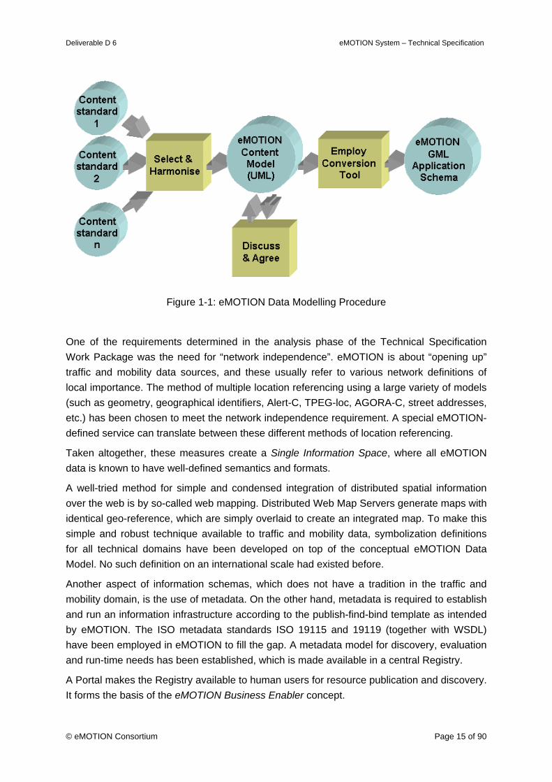
Figure 1-1: eMOTION Data Modelling Procedure
One of the requirements determined in the analysis phase of the Technical Specification Work Package was the need for “network independence”. eMOTION is about “opening up” traffic and mobility data sources, and these usually refer to various network definitions of local importance. The method of multiple location referencing using a large variety of models (such as geometry, geographical identifiers, Alert-C, TPEG-loc, AGORA-C, street addresses, etc.) has been chosen to meet the network independence requirement. A special eMOTION-defined service can translate between these different methods of location referencing.
Taken altogether, these measures create a Single Information Space, where all eMOTION data is known to have well-defined semantics and formats.
A well-tried method for simple and condensed integration of distributed spatial information over the web is by so-called web mapping. Distributed Web Map Servers generate maps with identical geo-reference, which are simply overlaid to create an integrated map. To make this simple and robust technique available to traffic and mobility data, symbolization definitions for all technical domains have been developed on top of the conceptual eMOTION Data Model. No such definition on an international scale had existed before.
Another aspect of information schemas, which does not have a tradition in the traffic and mobility domain, is the use of metadata. On the other hand, metadata is required to establish and run an information infrastructure according to the publish-find-bind template as intended by eMOTION. The ISO metadata standards ISO 19115 and 19119 (together with WSDL) have been employed in eMOTION to fill the gap. A metadata model for discovery, evaluation and run-time needs has been established, which is made available in a central Registry.
A Portal makes the Registry available to human users for resource publication and discovery. It forms the basis of the eMOTION Business Enabler concept.

Deliverable D 6 eMOTION System – Technical Specification
© eMOTION Consortium Page 16 of 90
The eMOTION Service definitions first and foremost make use of existing standards. Regard-ing data provision and mapping these are the proven geo-standards from OGC, however, where the geo-domain is left, main-stream standards are employed, particularly from OASIS and W3C. These standards are used as-is, however when special eMOTION requirements have to be considered, profiles of these standards have been defined. Use of most of these standards is compliant to current large scale SDI endeavours such as INSPIRE.
Other service definitions, for which no standards have been found, have been conceptually modelled in UML. These definitions also have been automatically transformed to run-time-usable service definitions (WSDL) by means of MDA methods. SOAP is consequently made use of to ensure an environment, where security information according to main-stream stan-dards (such as WS-Security) can be seamlessly applied.
1.3 Main Results
The Work Package has created the intended results, and they are documented in the eMO-TION Technical Specification document set, which consists of:
(1) This document, the eMOTION System – Technical Specification (from other parts referred to as the main document),
(2) eMOTION System – Technical Specification: Appendix 1 eMOTION Data Model
(3) eMOTION System – Technical Specification: Appendix 2 eMOTION Service Interface Definition
(4) eMOTION System – Technical Specification: Appendix 3 eMOTION Mapping Specifications
(5) eMOTION System – Technical Specification: Appendix 4 eMOTION Registry Information Model
(6) The eMOTION Model, available as Enterprise Architect repository, as binary model repository (EAP) or equivalent XMI export.
(7) The eMOTION GML Application Schema documents generated from the eMOTION Data Model, and
(8) The eMOTION WSDL documents defining eMOTION Service interfaces. These have been automatically generated from the eMOTION Service Model.
The main document (1) basically provides an introduction into the eMOTION System, which is specified in detail elsewhere. There are only few sections contained in the main document, which are not described in more detail in the eMOTION Model or in one of the Appendixes.
The eMOTION Data Model is specified as part of the eMOTION Model (6) and in Appendix 1 (2), which adds explanatory text. The eMOTION Data Model is the specification component with the deepest specification depth. It constitutes the main result of the eMOTION Technical Specification.
Deliverable D 6 eMOTION System – Technical Specification
© eMOTION Consortium Page 17 of 90
The eMOTION GML Application Schema (7) is automatically derived information. Where doubts exist in the application schema, the original Data Model should be consulted for clari-fication.
The eMOTION Service Model is specified in Appendix 2 (3) as far as eMOTION Services have been profiled from existing standards. In these cases these standards together with the profile definition constitute the eMOTION specification. eMOTION Services, which do not profile existing standards are defined in the eMOTION Service Model, which is part of the eMOTION Model (6). In these cases Appendix 2 (3) adds explanatory text.
Again the eMOTION WSDL documents (8) are automatically derived. The original Service Model carries the significant definitions.
Mapping Specifications are solely contained in Appendix 3 (4).
The eMOTION Registry Information Model in Appendix 4 (5) follows a rather minimalistic approach, because there are currently no “hard” requirements available for a Registry in the traffic and mobility domain. It has to be expected that the eMOTION RIM definitions must be extended as soon as practical experience is gained with the approach.
1.4 Deliverable Overview
The eMOTION Technical Specification is basically structured according to the Reference Model of Open Distributed Processing (RM-ODP) as set out by [ISO 10746-1, 1998].
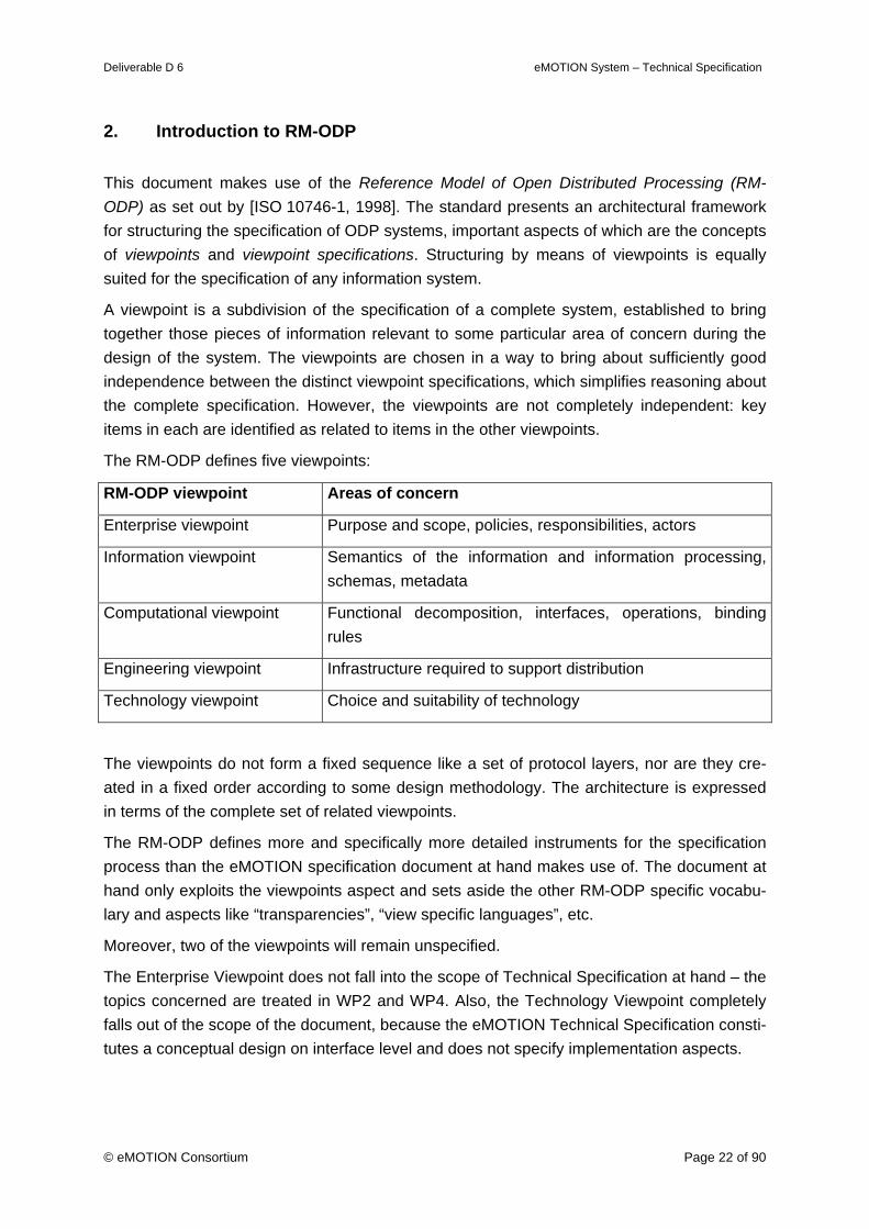
The RM-ODP approach is explained in a first chapter. The following parts of the RM-ODP structure are used in the eMOTION Technical Specification:
Information viewpoint Semantics of the information and information processing, sche-mas, metadata
Computational viewpoint Functional decomposition, interfaces, operations, binding rules
Engineering viewpoint Infrastructure required to support distribution
An introductory chapter gives an outline of the eMOTION technical architecture in an infor-mative and generally understandable way. While primarily aimed at providing information to the non-technical reader, the chapter also gives motivational background and a view on the “big picture” of eMOTION as seen from the perspective of other eMOTION Work-Packages.
eMOTION defines a service-oriented architecture, which gets its bearings from standards and specifications which have proven their value in creating Spatial Data Infrastructures (SDIs) including the forthcoming European SDI, INSPIRE.
The eMOTION approach rests on two concepts, which can be characterised by two notions:
• eMOTION Single Information Space: Data and Service offerings follow a uniform sin-gle schema and encoding
Deliverable D 6 eMOTION System – Technical Specification
© eMOTION Consortium Page 18 of 90
• eMOTION Business Enabler: Central Portal and Registry supporting the publish-find-bind template and giving access to all required resources.
1.4.1 Information Viewpoint
The Information Viewpoint is concerned with the kinds of information handled by the eMO-TION system and the constraints on the use and interpretation of that information. It concen-trates on the semantics of the information and information processing performed.
The eMOTION Data Model is the central supporting pillar of the eMOTION Technical Speci-fication. It makes sure that – independent from representation of the eMOTION objects in databases or exchange formats – every eMOTION Service and Application can understand and interpret eMOTION data. The eMOTION Data Model is the conceptual basis for enabling Services to deliver uniform data in the eMOTION Single Information Space.
The eMOTION Data Model is exactly specified in the eMOTION Model and is described in Appendix 1.
It is encoded and documented in Unified Modelling Language (UML). The model has been developed by harmonising several international and European standards along the lines of the ISO 19100 series of Geographic Information Standards.
The following sub-packages are contained in the eMOTION Data Model.
• Common
• Network
• LocationReference
• Directories
• TrafficRelatedInformation
• PublicTransport
• FixedInfrastructure
• JourneyPlanning
• Weather
The exchange format for eMOTION data is defined by an Application Schema of Geography Markup Language (GML).
The Information Metadata Model is an additional schema, the objects of which are used to describe the eMOTION objects proper. Metadata is used to publish, find and evaluate eMO-TION information sources in the distributed eMOTION environment. Other metadata is needed to make use of eMOTION data.
The eMOTION Registry Information Model is defined in Appendix 4.
It is based on the ebXML Registry Information Model (RIM). It is prepared to be implemented on an ebXML Registry Service (RS) instance. Both ebXML RIM and RS are OASIS stan-
Deliverable D 6 eMOTION System – Technical Specification
© eMOTION Consortium Page 19 of 90
dards.
The Information Viewpoint also specifies which Coordinate Reference Systems are to be available in eMOTION resources and how they have to be addressed.
The same applies to Measures and Units of Measure. In particular the weather sub-model of eMOTION makes rich use of various measures and units, the addressing of which is de-fined.
The Information Viewpoint also treats the aspect of Visualisation and Mapping.
Appendix 3 defines layers and symbolisations tied to the technical domains of eMOTION. The content of the layers is described in reference to the eMOTION Data Model.
1.4.2 Computational Viewpoint
The Computational Viewpoint is concerned with the functional decomposition of the system into a set of entities that interact at interfaces.
The first topic treated are Encodings.
The eMOTION Encoding for Data Exchange is defined by an Application Schema in Geog-raphy Markup Language (GML), [ISO 19136, 2007]. The latter is automatically derived from the Conceptual eMOTION Data Model, which has been developed in UML along the lines of the ISO 19100 series of standards by means of the standardised process documented in ISO 19136 (Appendix D and E).
Other Encodings proposed for use in eMOTION are:
Encodings for Visual Information (favoured formats are PNG, GIF and JPEG),
Encodings for Coverage Data (BUFR),
Encodings for Multimedia and Audio Information (Multimedia: MPEG-4, 3GPP, Matroska; Audio: MPEG-4 Part 3, MPEG-1, Vorbis; Video: H.264, Theora)
The eMOTION Service Interface Definitions constitute another important supporting pillar of the Technical Specification, comparable in importance to the eMOTION Data Model. The Service Interface Definitions make sure that the eMOTION system components can commu-nicate on the basis of well-known interfaces.
The eMOTION Service Interface Definition is described in Appendix 2 and partly specified in the eMOTION Model.
Services have been specified in one of two ways: 1. wherever possible, existing service stan-dards have been used, especially from OGC and OASIS. In these cases profiles have been defined. 2. If a re-use of existing service definitions has not been possible, eMOTION Ser-vices have been specified in formal UML models. These models were then automatically translated into service describing WSDL documents.
The following eMOTION Service classes have been defined.
• Data Services

Deliverable D 6 eMOTION System – Technical Specification
© eMOTION Consortium Page 20 of 90
• Mapping Services
• Event Notification Service
• Inter-modal Journey Planners
• Geo-Directory Services
• Reference Translation Services
• Positioning Services
• Registry Services
• Rights Management Services
• Accounting, Billing and Payment Services
• Natural Language Translation Services
The Service Metadata Model specifies the data necessary to describe the service interfaces of eMOTION. This metadata is necessary to let services automatically bind to eMOTION ser-vices. Part of the specified model is also used to discover eMOTION by their service inter-face properties.
A detailed description of the eMOTION Service Metadata Model is available in Appendix 4.
Another issue treated in the Computational Viewpoint is captioned Service Chains for eMOTION Use Cases. This section examines whether the proposed eMOTION Use Cases, which were described in eMOTION Deliverable 2, chapter 3, can indeed be constructed by appropriately “wiring” the eMOTION Service components defined in the Technical Specifica-tion. As it turns out this is indeed possible,
1.4.3 Engineering Viewpoint
The Engineering Viewpoint is concerned with the infrastructure required to support the distri-bution of services and information sources of the eMOTION system. It focuses on the ques-tion how the interactions between the eMOTION service are accomplished using the defined interfaces.
The first issue treated here is the Communication Model. It defines the principle workings of the eMOTION distributed environment.
The communication model of the eMOTION architecture is based on the requirements of a typical distributed SOA. It focuses on protocols and standards suitable to establish an effi-cient and reliable communication model for the exchange of information between nodes. Generally, eMOTION uses SOAP and WSDL along the guidelines proposed by the Web Ser-vice Interoperability Organization (WS-I).
Another issue treated in the Engineering Viewpoint chapter is Interaction of eMOTION Components. Here general information is given about the distribution and interaction of components and nodes in the eMOTION network. The text is meant to be informative only, and shall not be understood as a strict definition.

Deliverable D 6 eMOTION System – Technical Specification
© eMOTION Consortium Page 21 of 90
Finally an Identifier Model is defined. All features (objects) instances according to the eMO-TION Data Model require unique and persistent identifiers. These are usually database-generated strings, however, a list of feature types requires the use of identifiers, which are part of the model semantics.
Identifiers in eMOTION consist of a globally unique prefix, which identifies the eMOTION Service, where the identified object originates and a local postfix generated by the Service or found in the data.
Deliverable D 6 eMOTION System – Technical Specification
© eMOTION Consortium Page 22 of 90
2. Introduction to RM-ODP
This document makes use of the Reference Model of Open Distributed Processing (RM-ODP) as set out by [ISO 10746-1, 1998]. The standard presents an architectural framework for structuring the specification of ODP systems, important aspects of which are the concepts of viewpoints and viewpoint specifications. Structuring by means of viewpoints is equally suited for the specification of any information system.
A viewpoint is a subdivision of the specification of a complete system, established to bring together those pieces of information relevant to some particular area of concern during the design of the system. The viewpoints are chosen in a way to bring about sufficiently good independence between the distinct viewpoint specifications, which simplifies reasoning about the complete specification. However, the viewpoints are not completely independent: key items in each are identified as related to items in the other viewpoints.
The RM-ODP defines five viewpoints:
RM-ODP viewpoint Areas of concern
Enterprise viewpoint Purpose and scope, policies, responsibilities, actors
Information viewpoint Semantics of the information and information processing, schemas, metadata
Computational viewpoint Functional decomposition, interfaces, operations, binding rules
Engineering viewpoint Infrastructure required to support distribution
Technology viewpoint Choice and suitability of technology
The viewpoints do not form a fixed sequence like a set of protocol layers, nor are they cre-ated in a fixed order according to some design methodology. The architecture is expressed in terms of the complete set of related viewpoints.
The RM-ODP defines more and specifically more detailed instruments for the specification process than the eMOTION specification document at hand makes use of. The document at hand only exploits the viewpoints aspect and sets aside the other RM-ODP specific vocabu-lary and aspects like “transparencies”, “view specific languages”, etc.
Moreover, two of the viewpoints will remain unspecified.
The Enterprise Viewpoint does not fall into the scope of Technical Specification at hand – the topics concerned are treated in WP2 and WP4. Also, the Technology Viewpoint completely falls out of the scope of the document, because the eMOTION Technical Specification consti-tutes a conceptual design on interface level and does not specify implementation aspects.
Deliverable D 6 eMOTION System – Technical Specification
© eMOTION Consortium Page 23 of 90
3. General Architecture
This chapter gives an outline of the eMOTION technical architecture in an informative and generally understandable way. While primarily aiming at providing information to the non-technical reader, the chapter also gives motivational background and a view on the “big pic-ture” of eMOTION as seen from the perspective of other eMOTION work packages.
3.1 Motivation
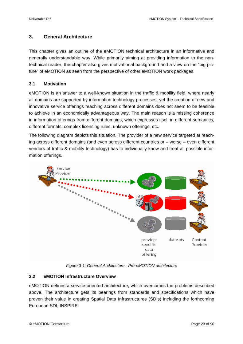
eMOTION is an answer to a well-known situation in the traffic & mobility field, where nearly all domains are supported by information technology processes, yet the creation of new and innovative service offerings reaching across different domains does not seem to be feasible to achieve in an economically advantageous way. The main reason is a missing coherence in information offerings from different domains, which expresses itself in different semantics, different formats, complex licensing rules, unknown offerings, etc.
The following diagram depicts this situation. The provider of a new service targeted at reach-ing across different domains (and even across different countries or – worse – even different vendors of traffic & mobility technology) has to individually know and treat all possible infor-mation offerings.
Figure 3-1: General Architecture - Pre-eMOTION architecture
3.2 eMOTION Infrastructure Overview
eMOTION defines a service-oriented architecture, which overcomes the problems described above. The architecture gets its bearings from standards and specifications which have proven their value in creating Spatial Data Infrastructures (SDIs) including the forthcoming European SDI, INSPIRE.
Deliverable D 6 eMOTION System – Technical Specification
© eMOTION Consortium Page 24 of 90
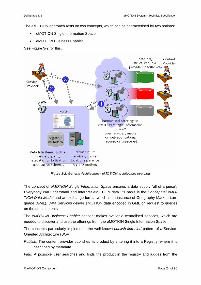
The eMOTION approach rests on two concepts, which can be characterised by two notions:
• eMOTION Single Information Space
• eMOTION Business Enabler
See Figure 3-2 for this.
Figure 3-2: General Architecture - eMOTION architecture overview
The concept of eMOTION Single Information Space ensures a data supply “all of a piece”. Everybody can understand and interpret eMOTION data. Its basis is the Conceptual eMO-TION Data Model and an exchange format which is an instance of Geography Markup Lan-guage (GML). Data Services deliver eMOTION data encoded in GML on request to queries on the data contents.
The eMOTION Business Enabler concept makes available centralised services, which are needed to discover and use the offerings from the eMOTION Single Information Space.
The concepts particularly implements the well-known publish-find-bind pattern of a Service-Oriented Architecture (SOA).
Publish: The content provider publishes its product by entering it into a Registry, where it is described by metadata.
Find: A possible user searches and finds the product in the registry and judges from the
Deliverable D 6 eMOTION System – Technical Specification
© eMOTION Consortium Page 25 of 90
available metadata whether he or she can make use of the offering.
Bind: The user’s software directly “binds” to the offering (for example a service instance) and uses it. Using it, it utilises further metadata, which are available in the registry (so-called use-metadata).
3.3 eMOTION Single Information Space
Its basis is the Conceptual eMOTION Data Model (encoded in Unified Modelling Language, UML), which has been developed by harmonising several international and European stan-dards along the lines of the ISO 19100 Geographic Information Standards.
It includes the domains of
• Individual Traffic (on the basis of DATEX2),
• Public Transport (Transmodel, IFOPT, SIRI and TPEG),
• Weather,
• Location Based Services and
• Inter-modal Transport Planning.
The exchange format for eMOTION data is defined by an Application Schema of Geography Markup Language (GML). The latter is automatically derived from the Conceptual eMOTION Data Model by means of the standardised process documented in ISO 19136 (Appendix E).
Web Feature Services (WFS), as specified by the Open Geospatial Consortium (OGC) are leveraged as the basic service entities responsible for making eMOTION content available for its use by service providers. Such services are called Data Services.
A WFS offers a query interface, which allows to select data entities (traditionally called fea-tures) over the web. Queries are composed of logical combinations of spatial and scalar – “normal” – properties. Other prominent service entities belonging to the Single Information Space are OGC Web Map Server (WMS), Journey Planning Services, and Directory Ser-vices.
“Rights Management” Services protect the data from unauthorised use.
3.4 eMOTION Business Enabler
The eMOTION Business Enabler concept makes available centralised services, which are needed to discover and use the offerings from the eMOTION Single Information Space.
A web application (the eMOTION Portal) makes the Registry service and consequently the Single Information Space accessible to humans. The Portal allows the published information to be searched and suitable offerings to be detected, visualised and evaluated. It also gives human users access to infrastructure services. Of course, it also owns a publication interface where content providers can register their resources (services, applications, and data) and supply the necessary metadata to describe them.
Further offerings in the eMOTION Business Enabler are centralised infrastructure services
Deliverable D 6 eMOTION System – Technical Specification
© eMOTION Consortium Page 26 of 90
such as translation services for geo-referencing, gazetteers and positioning services.
The Registry Service is the core of the Business Enabler concept. It is based on the OASIS ebXML specification, both ebRIM and ebRS.
It contains:
• Discovery Metadata,
• Evaluation Metadata, and
• Use Metadata.
Both Discovery Metadata and Evaluation Metadata are based on the ISO 19115 standard. While the Evaluation Metadata is chosen to be directly the ISO 19139 representation of the ISO 19115 Metadata definition, Discovery Metadata constitutes a simplified Core Information Model (CIM) derived from ISO 19115 comprising metadata on the offerings of eMOTION data, services and applications. Discovery Metadata can be searched, while Evaluation Metadata which is more extensive, however, cannot be searched.
Use Metadata comprises Registry models for:
• Feature Catalogue and eMOTION Schema
• Codelist Register
• Coordinate Reference Systems Register
• Measures and Units of Measure Register
• Service Metadata Register
• Identifier Namespace Register
• Network Reference Register
• Notification Subscription Register
• Licences and Rights Management Register
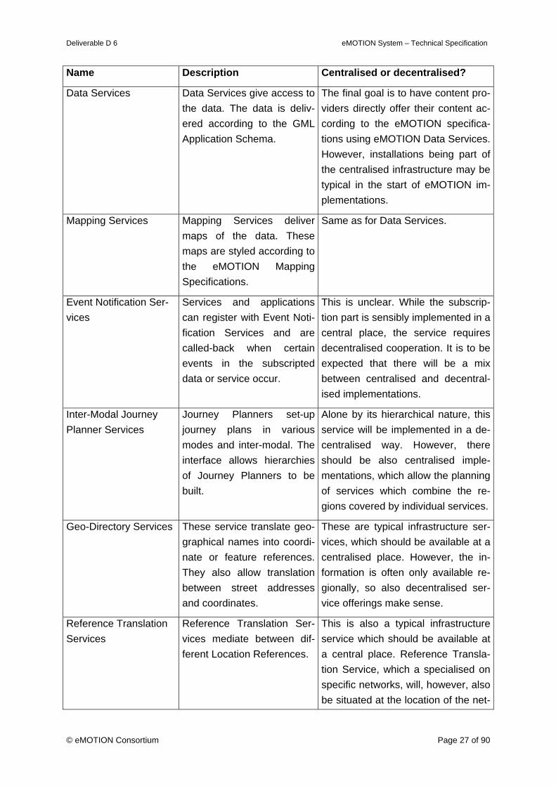
3.5 eMOTION Services Overview
The distinction between centralised service offerings, combined in the notion of the eMO-TION Business Enabler, and decentralised ones abstracted in the notion eMOTION Single Information Space, is not so definite after all.
Examples: While the eMOTION Portal application only makes sense if offered at a central-ised, well-known place, even a Registry service may be constructed in a federated way, where several Registries are working together in executing queries. On the other hand, Data Services seem to be the typical decentralised service entities. However, it is also possible that some important data offering may be part of the centralised eMOTION Infrastructure, especially when eMOTION starts being implemented and not every content provider is con-vinced that eMOTION is a good thing to invest into.
In the following we will discuss these matters on a service-by-service basis:
Deliverable D 6 eMOTION System – Technical Specification
© eMOTION Consortium Page 27 of 90
Name Description Centralised or decentralised?
Data Services Data Services give access to the data. The data is deliv-ered according to the GML Application Schema.
The final goal is to have content pro-viders directly offer their content ac-cording to the eMOTION specifica-tions using eMOTION Data Services. However, installations being part of the centralised infrastructure may be typical in the start of eMOTION im-plementations.
Mapping Services Mapping Services deliver maps of the data. These maps are styled according to the eMOTION Mapping Specifications.
Same as for Data Services.
Event Notification Ser-vices
Services and applications can register with Event Noti-fication Services and are called-back when certain events in the subscripted data or service occur.
This is unclear. While the subscrip-tion part is sensibly implemented in a central place, the service requires decentralised cooperation. It is to be expected that there will be a mix between centralised and decentral-ised implementations.
Inter-Modal Journey Planner Services
Journey Planners set-up journey plans in various modes and inter-modal. The interface allows hierarchies of Journey Planners to be built.
Alone by its hierarchical nature, this service will be implemented in a de-centralised way. However, there should be also centralised imple-mentations, which allow the planning of services which combine the re-gions covered by individual services.
Geo-Directory Services These service translate geo-graphical names into coordi-nate or feature references. They also allow translation between street addresses and coordinates.
These are typical infrastructure ser-vices, which should be available at a centralised place. However, the in-formation is often only available re-gionally, so also decentralised ser-vice offerings make sense.
Reference Translation Services
Reference Translation Ser-vices mediate between dif-ferent Location References.
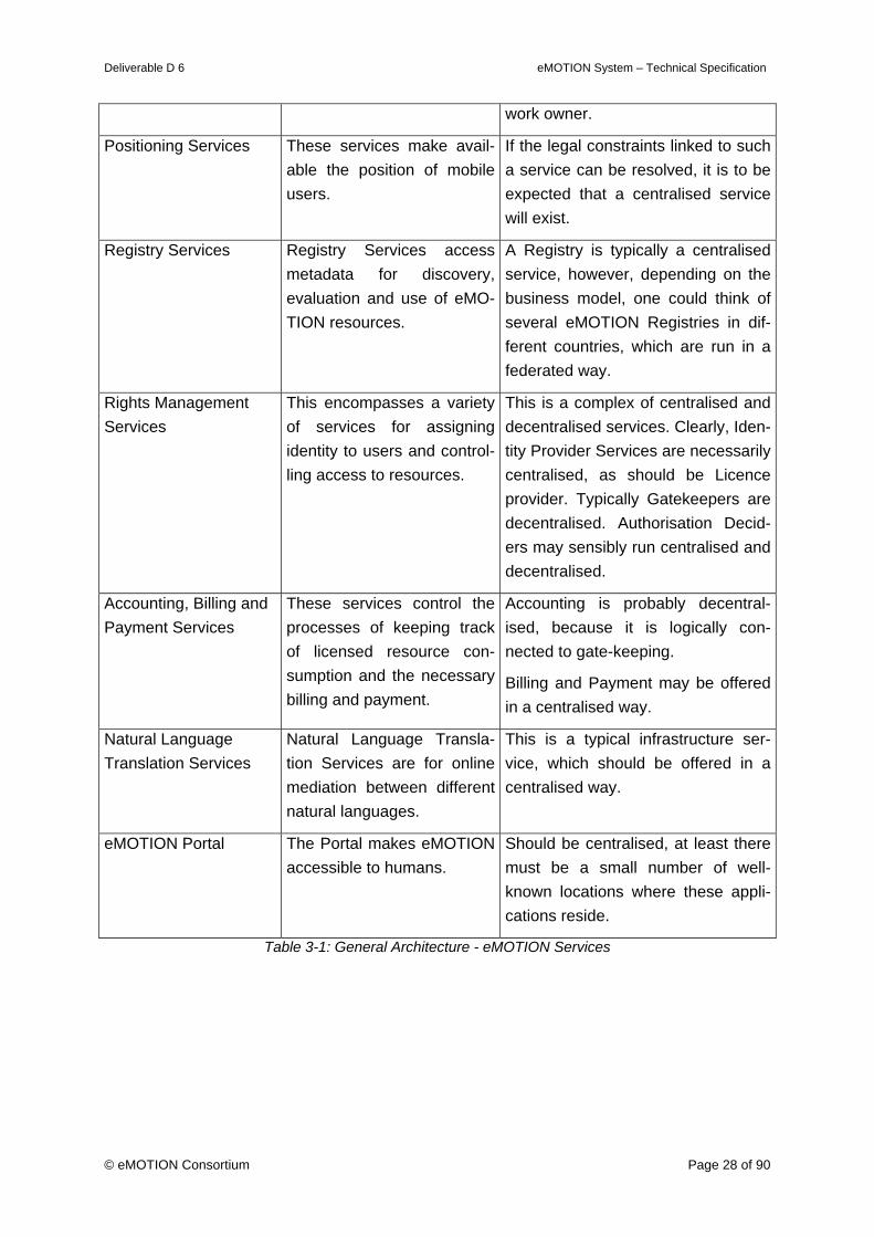
This is also a typical infrastructure service which should be available at a central place. Reference Transla-tion Service, which a specialised on specific networks, will, however, also be situated at the location of the net-
Deliverable D 6 eMOTION System – Technical Specification
© eMOTION Consortium Page 28 of 90
work owner.
Positioning Services These services make avail-able the position of mobile users.
If the legal constraints linked to such a service can be resolved, it is to be expected that a centralised service will exist.
Registry Services Registry Services access metadata for discovery, evaluation and use of eMO-TION resources.
A Registry is typically a centralised service, however, depending on the business model, one could think of several eMOTION Registries in dif-ferent countries, which are run in a federated way.
Rights Management Services
This encompasses a variety of services for assigning identity to users and control-ling access to resources.
This is a complex of centralised and decentralised services. Clearly, Iden-tity Provider Services are necessarily centralised, as should be Licence provider. Typically Gatekeepers are decentralised. Authorisation Decid-ers may sensibly run centralised and decentralised.
Accounting, Billing and Payment Services
These services control the processes of keeping track of licensed resource con-sumption and the necessary billing and payment.
Accounting is probably decentral-ised, because it is logically con-nected to gate-keeping.
Billing and Payment may be offered in a centralised way.
Natural Language Translation Services
Natural Language Transla-tion Services are for online mediation between different natural languages.
This is a typical infrastructure ser-vice, which should be offered in a centralised way.
eMOTION Portal The Portal makes eMOTION accessible to humans.
Should be centralised, at least there must be a small number of well-known locations where these appli-cations reside.
Table 3-1: General Architecture - eMOTION Services

Deliverable D 6 eMOTION System – Technical Specification
© eMOTION Consortium Page 29 of 90
4. Information Viewpoint
This chapter is concerned with the kinds of information handled by the eMOTION system and the constraints on the use and interpretation of that information. It concentrates on the se-mantics of the information and information processing performed.
The eMOTION Data Model constitutes the central part of the semantics of eMOTION. It makes sure that – independent from representation of the eMOTION objects in databases or exchange formats – eMOTION objects can be relied upon to mean the same within the eMOTION system.
The Information Metadata Model is an additional application schema, the objects of which are used to describe the eMOTION objects proper. Metadata is used to publish, find and evaluate eMOTION information sources in the distributed eMOTION environment.
Other metadata is needed to make use of eMOTION data. To these belong Coordinate Ref-erence Systems.
Other information standards defined in this chapter deal with the provision of maps and the content of audible presentations.
4.1 eMOTION Data Model
The eMOTION Data Model is the central supporting pillar of the eMOTION Technical Specifi-cation. It ensures a data supply “all of a piece” in a “common language” enabling every eMOTION Service and Application to understand and interpret eMOTION data. The eMO-TION Data Model is the conceptual basis for enabling Services to deliver uniform data in the eMOTION Single Information Space.
The eMOTION Data Model is encoded and documented in Unified Modelling Language (UML). The model has been developed by harmonising several international and European standards along the lines of the ISO 19100 series of Geographic Information Standards. See the discussion of the particular sub-models below.
The exchange format for eMOTION data is defined by an Application Schema of Geography Markup Language (GML). The latter is automatically derived from the Conceptual eMOTION Data Model by means of the standardised process documented in ISO 19136 (see Appendix D and E).
The eMOTION Data Model is specified and documented in the eMOTION UML Schema (Package: EMotionData), which has been created using the Enterprise Architect CASE Tool3. The binary model repository or equivalent XMI exports are available and are part of the eMOTION Technical Specification.
3 By Sparx Systems, http://www.sparxsystems.com.au/
Deliverable D 6 eMOTION System – Technical Specification
© eMOTION Consortium Page 30 of 90
The model is based on
Hollow World,
a free ISO 19100 Modelling Framework by Simon Cox from Commonwealth Scientific and Industrial Research Organisation (CSIRO) in Australia.
See https://www.seegrid.csiro.au/twiki/bin/view/AppSchemas/HollowWorld.
The framework provides the ISO 19100 series of standards UML model together with docu-mentation and how to use this to generate GML from it along the lines of the standard in a model driven architecture process.
A description of the eMOTION Data Model is given in
Appendix 1 – eMOTION Data Model
The following sections give a short overview over the particular sub-packages of the eMO-TION Data Model.
4.1.1 Common
EMotionFeature is the base class of all eMOTION Features. Features are all those object classes, which have identity and carry essential data from eMOTION's universe of discourse. Examples are Messages or ParkingPlaces or StopPoints, etc.
EMotionObject is the base class of all eMOTION Objects. "Objects" are those object classes, which have identity like features, but play only an auxiliary role in the object model. Examples are LocationReferences.
The subpackage Common Enumerations contains enumerations, or groups of enumerations, which are used, or deemed to be useful, within more than one application package. Included are enumerations from the TPEG standards.
The Situation package is based on the DATEXII Situation model, and provides a structured manner in which to describe a Situation in terms of related circumstances, known as abstract SituationRecords. Concrete children of these are described in other packages.
4.1.2 Network
The network package describes a basic network elements, namely links (typically corre-sponding to road, rail and walkway sections) and nodes (corresponding to junctions for links). The mode is simple covering geometry and some classification of the elements.
4.1.3 LocationReference
The Location Reference provides the ability to locate features. Locations may be points, lines or areas, or collections thereof.
GeometryLocationReference provides a location by providing coordinates
The LinearReferenceLocationReference, allows a location to be specified at a distance along
Deliverable D 6 eMOTION System – Technical Specification
© eMOTION Consortium Page 31 of 90
and offset from a specified network link.
Street Address Location Reference allows features to be located with respect to an Ad-dresss, and contains the emotionAddress type, used for describing addresses throughout the data model.
Geographical Name Location Reference allows a location to be described in terms of a known LocationInstance in a Gazetteer.
Descriptive Location Reference based on TPEG Location Description allows a location to be described in a machine readable and human readable manner.
In terms of standard location reference structures, eMOTION describes Alert-C and TPEG Locations, and references the Agora-C standard. These standards between them support referencing by precoded locations, coordinates, links and nodes, linear referencing, crossed streets and addresses.
4.1.4 Directories
The Geography package contains the eMOTION Gazetteer model, a Geographical directory of LocationInstances, identified by their GeographicalNames, which describes their positions and supports hierarchical structures, such as might be useful for describing area subdivi-sions. The position itself may be any GM_Object (including points, curves and areas).
The PointOfInterest describes categorized and grouped PointsOfInterest. A specialised POI to describe the relevant details of vehicle parking facilities is described in the subpackage Parking. This ParkingPoint is based on a draft description of the TPEG-PKI standard, as de-scribed at www.itsregistry.org.uk.
4.1.5 TrafficRelatedInformation
The TrafficRelatedInformation package contains the classes for describing information mes-sages on roads, such as traffic flow data, traffic messages, road works, etc, and is based on the DATEXII standard.
The TrafficRelatedSituation subpackage contains the TrafficSituationRecord, inherited from SituationRecord. To this TrafficSituationRecord, information including the Cause, Impact, related Advice and message Validity may be appended. TrafficSituationRecord is further specialised into TrafficElement, OperatorAction or NonRoadEventInformation. TrafficElement describes events not initiated by the traffic operator. AbnormalTraffic, Accident, Activities, Conditions, Obstruction, PoorRoadInfrastructure and RoadWeatherAndEnvironmentEvents. OperatorAction describes actions by the road operator to avoid accidents or congestion, namely Roadworks, NetworkManagement, SignSetting and Roadside Assistance. Non-RoadEventInformation describes ParkingSituations, TransitInformation (information about public transport services relevant to road users) and Service Disruption (disruptive events at roadway service/rest areas and fuelling facilities).
The TrafficRelatedData subpackage contains the structures necessary to publish measured
Deliverable D 6 eMOTION System – Technical Specification
© eMOTION Consortium Page 32 of 90
and elaborated data, as well as the BasicDataValue package used to describe the values for these publications. The MeasuredDataPublication is used to describe measured data which has been derived from equipment at specific measurement sites, while ElaboratedDataPubli-cation contains information processed by the traffic centre for specific locations of interest. BasicDataValue is further specialized to describe travel times, traffic status and trend, envi-ronment values and traffic values (such as speeds, headways, flows and concentrations).
4.1.6 PublicTransport
The Crafts package describes basic details relating to public transport vehicles.
The ServiceDescription package describes the basis upon which public transport services, are described. It is based on the TransModel standard, and describes features such as Ser-vices, Lines, Operators, Routes and ServicePatterns (StopPoints and ServiceLinks), as well as ConnectionLinks and AccessLinks used to describe logical paths between StopPoints and Places.
The Schedule package, which is based on the SIRI standard, essentially describes timing information for scheduled services, including scheduled timetables, timetable changes, pre-dicted and achieved arrivals and departures for services such real time information.
The ServiceInformationMessages package contains the PublicTransportSituationRecord, which provides information on situations relevant to public transport users, such as disruption to routes and timings, and the reasons for them. It is based on the TPEG-PTI standard, albeit cast into the common SituationRecord form, but linked to the ServiceDescription and Sched-ule packages where appropriate.
Fares is a placeholder package where Fares information will be modelled in a later version. Similarly flexible is placeholder package where information on flexibly routed services will be stored in a later version.
4.1.7 FixedInfrastructure
The FixedInfrastructure package, which is essentially the IFOPT model expressed in the eMOTION framework, describe the layout, facilities and links TransModel Places, namely origin, destination and interchange features. The main package is the StopPlace package, which describes features ranging from roadside bus stops to complex interchanges such as railway stations and airports. The Parking package describes a ParkingPlace, a type of Stop-Place describing a Parking. The PlaceOfInterest describes place information for PointsOf-Interest.
The Navigation package describes in detail links between StopPlaceSpaces within a Stop-Place or links between StopPlaces (ConnectionLinks) as well as between StopPlaces and more generic Places, such as PlacesOfInterest and AddressablePlaces (AccessLinks). The Equipment package describes equipment (such as ticketing facilities, elevators and assis-tance services) located at Places, as well as on public transport vehicles. The accessibility package allows an AccessibilityAssessment to be appended to Places and their components.
Deliverable D 6 eMOTION System – Technical Specification
© eMOTION Consortium Page 33 of 90
FixedInfrastructure Places are linked to less detailed corresponding feature - such as Stop-Points, Parkings, PointOfInterests, ConnectionLinks and AccessLinks - with various types of Assignment, as described in the Assignments package.
The FixedInfrastructure package is most useful for JourneyPlanning applications.
4.1.8 JourneyPlanning
The JourneyPlanning package describes the data structures necessary to describe Journey-Plans.
4.1.9 Weather
The weather package is based on the DATEX II standard, and includes environment data models, which are non weather related. As for traffic information, information messages are provided in terms of SituationsRecords, while WeatherMeasurements are available as both MeasuredDataPublications and ElaboratedDataPublications.
The WeatherMeaurements package contains both environment (such as those for precipita-tion intensity, wind speed and direction) and surfaces measurements (such snow or water film depth) used in the other subpackages.
The SituationRecord relevant features include WeatherRelatedRoadConditions (such as sur-face temperature or snow depth), EnvironmentConditions (be these weather related, or those not so such as noise levels) and WeatherConditions.
4.2 Information Metadata Model
This section gives an introduction into the eMOTION Registry Information Model, which is based on the ebXML Registry Information Model (RIM).
The eMOTION registry services and the eMOTION registry service information model are defined on the basis of the following documents:
"ebXML Registry Services and Protocols Version 3.0", Organization for the Ad-
vancement of Structured Information Standards (OASIS), 2005. [ebRS]
http://docs.oasis-open.org/regrep/v3.0/specs/regrep-rs-3.0-os.pdf
"ebXML Registry Information Model Version 3.0", Organization for the Advancement
of Structured Information Standards (OASIS), 2005. [ebRIM]
http://docs.oasis-open.org/regrep/v3.0/specs/regrep-rim-3.0-os.pdf
The metadata is primarily used to describe objects or collection of objects following the eMO-TION Data Model for the purpose of finding and evaluating them in eMOTION Registries.
Additionally, a Registry Model is created, which defines which other metadata items are nec-essary for using the eMOTION data and services shall be made available for retrieval.
Deliverable D 6 eMOTION System – Technical Specification
© eMOTION Consortium Page 34 of 90
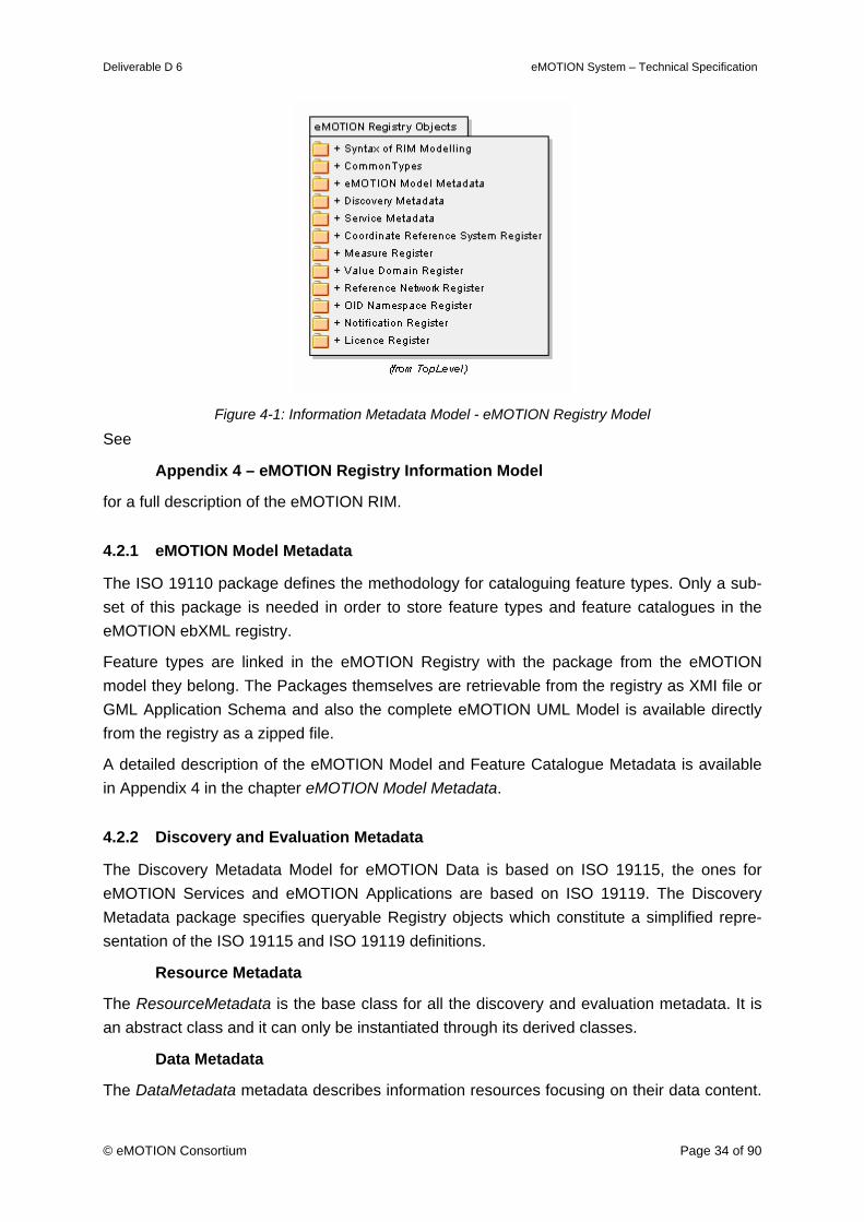
Figure 4-1: Information Metadata Model - eMOTION Registry Model
See
Appendix 4 – eMOTION Registry Information Model
for a full description of the eMOTION RIM.
4.2.1 eMOTION Model Metadata
The ISO 19110 package defines the methodology for cataloguing feature types. Only a sub-set of this package is needed in order to store feature types and feature catalogues in the eMOTION ebXML registry.
Feature types are linked in the eMOTION Registry with the package from the eMOTION model they belong. The Packages themselves are retrievable from the registry as XMI file or GML Application Schema and also the complete eMOTION UML Model is available directly from the registry as a zipped file.
A detailed description of the eMOTION Model and Feature Catalogue Metadata is available in Appendix 4 in the chapter eMOTION Model Metadata.
4.2.2 Discovery and Evaluation Metadata
The Discovery Metadata Model for eMOTION Data is based on ISO 19115, the ones for eMOTION Services and eMOTION Applications are based on ISO 19119. The Discovery Metadata package specifies queryable Registry objects which constitute a simplified repre-sentation of the ISO 19115 and ISO 19119 definitions.
Resource Metadata
The ResourceMetadata is the base class for all the discovery and evaluation metadata. It is an abstract class and it can only be instantiated through its derived classes.
Data Metadata
The DataMetadata metadata describes information resources focusing on their data content.
Deliverable D 6 eMOTION System – Technical Specification
© eMOTION Consortium Page 35 of 90
A DataMetadata object may point to the EMotionDataset, which it describes.
EMotionDataset could be:
• ElementaryData: describing a single data item;
• DataCollection: describing a collection of ElementaryData objects.
Service Metadata
Service Metadata are stored in the eMOTION Registry using a ServiceMetadata typed Ex-trinsicObject which is a specialization of the ResourceMetadata seen before. The eMOTION Service model is different from the one in [OGC-CIM, 2007]. A ServiceMetadata object may point to the EMotionService, which is derived from a WSDL:Service (see section 4.2.3 of this document) and could be linked with the EmotionDataset which it operates on.
Application Metadata
EMotionApplication represents an eMOTION application resource. Applications are not part of the eMOTION specification, however, they can be represented in the eMOTION Registry and evaluated through the attached ApplicationMetadata.
A detailed description of the eMOTION Discovery and Evaluation Metadata, along with the description of other discovery metadata not presented here, is available in Appendix 4 in the chapter Discovery and Evaluation Metadata.
4.2.3 Service Metadata
In eMOTION, web services are described through a WSDL document. In the eMOTION Reg-istry the OASIS WebService Profile [ebRIM-WS] is used to store metadata regarding the WSDL file. This profile is modified with the introduction of a specialized eMOTIONService class containing a classification of the Service, through the eMOTION Service taxonomy, and which may be linked with the ServiceMetadata describing it.
A detailed description of the eMOTION Service Information Model is available in Appendix 4 in the chapter Service Metadata.
4.2.4 Coordinate Reference System Register
A Coordinate Reference System (CRS) describes the spatial context of coordinates. Each CRS is stored in the eMOTION Registry as either
• a pointer to the EPSG Geodetic Parameter Registry, which can be found under http://www.epsg-registry.org/, or
• a GML CRSDictionary entry.
These representations are retrievable by name and description, and they are identified by an OGC-defined urn-code.
A detailed description of the eMOTION Coordinate Reference System Registry is available in
Deliverable D 6 eMOTION System – Technical Specification
© eMOTION Consortium Page 36 of 90
Appendix 4 in the chapter Coordinate Reference System Register.
4.2.5 Measure Register
In many geo-spatial applications, it is important to be able to associate units of measure to quantities. In practice, units of measure are often referenced from a dictionary. For that pur-pose in the eMOTION Registry, Units of Measure are stored as GML Dictionary entry and retrievable though the Measure ExtrinsicObject containing an identifier of the measure, which is a composition of the name of the eMOTION package (where the measure is defined) and its class name, and classified using the Measure type abbreviation.
A detailed description of the eMOTION Units of Measurement Register is available in Ap-pendix 4 in the chapter Measure Register.
4.2.6 Value Domain Register
The Value Domain Register can be used to query unknown values and find out to which Val-ueDomains (Enumerations or CodeLists) they belong. Information about Codelist or Enu-meration, contained in the eMOTION schema, are retrievable from the registry through a ValueDomain ExtrinsicObject containing an identifier, which is a composition of the name of the eMOTION package (where the ValueDomain is defined) and its class name, and classi-fied through its values for easily discovery. In case of Codelist more information are stored in an associated GML Dictionary entry.
A detailed description of the eMOTION Codelist Register is available in Appendix 4 in the chapter Value Domain Register.
4.2.7 OID Namespace Register
Feature identifiers will consist of a prefix, the feature identifier namespace, which identifies a service and a local identifier, which is assigned by the provider. The feature identifiers are stored in the registry through the OIDNamespace ExtrinsicObject. The service is linked to the feature identifier through a ServiceUsingNamespace Association.
A detailed description of the eMOTION Feature Identifier Namespace Registry is available in Appendix 4 in the chapter OID Namespace Register.
4.2.8 Reference Network Register
Location references can contain (and must in case of linear references to a network) meta-data which contains a string, which uniquely identifies a specific network dataset.
A Network ExtrinsicObject which contains the networkIdentifier is stored in the registry and linked to the eMOTION service instances, of type LRT_Service (Location Reference Transla-tion Service), that are capable of translate from (AsSource association) and/or to the specific Network Reference (AsTarget association).
A detailed description of the eMOTION Network Reference Registry is available in Appendix

Deliverable D 6 eMOTION System – Technical Specification
© eMOTION Consortium Page 37 of 90
4 in the chapter Reference Network Register.
4.2.9 Notification Register
For ease of management and discovery, subscription to notifications coming from the eMO-TION services are directly stored in the eMOTION Registry. When a subscription is created, the WSN (WS-Notification or Web Service Notification) document is stored in the registry and retrievable through the associated NotificationSubscription ExtrinsicObject.
In the Notification Register information about the Consumer, Producer and the Subscriber of the Service may also be stored. In the Subscriber case an SAML (Security Assertion Markup Language) document can also be retrieved from the registry containing information regarding authorization and authentication.
A detailed description of the eMOTION Notification Registry is available in Appendix 4 in the chapter Notification Register.
4.2.10 JourneyPlanningService Register
In eMOTION Journey calculation is typically distributed and may involve multiple instances of Journey Planner services. Using the Journey Planning Service Register a singular instance of a Journey Planner can query the registry to find out which JourneyPlanningService are available together with their basic capabilities in terms of mode of transport supported and area covered, described by an AdministrativeArea ExtrinsicObject.
A detailed description of the eMOTION Rights Management Related Registry is available in Appendix 4 in the chapter JourneyPlanningService Register.
4.2.11 License Register
The License Register is composed by two parts: the Licensing part and the License Offering:
• License is a documentation of legal Rights on one or more Resources, also informa-tion about the Issuer and the Licensee could be retrieved directly from the registry;
• LicenseOffering stores information for a set of restricted rights on some resource and could be associated with one or more PolicyTemplates that underlies a XACML document constraining access to the resource.
A detailed description of the eMOTION Rights Management Related Registry is available in Appendix 4 in the chapter License Register.
4.3 Coordinate Reference Systems
To uniquely identify a place on earth, coordinates require the designation of a coordinate reference system (CRS), and a multitude of such CRSs exist.
The conceptual eMOTION Data Model does not deal with CRSs explicitly. The same applies to the eMOTION exchange encoding, defined by means of the GML Application Schema. Principally, GML supports any CRS.
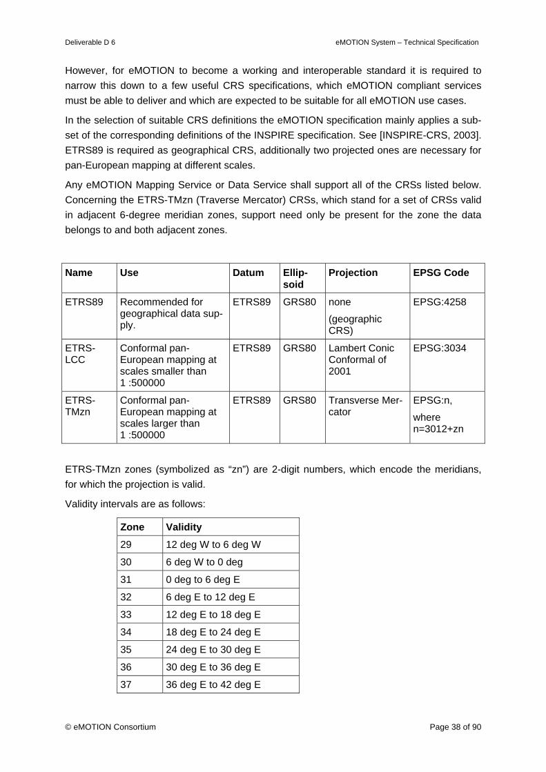
Deliverable D 6 eMOTION System – Technical Specification
© eMOTION Consortium Page 38 of 90
However, for eMOTION to become a working and interoperable standard it is required to narrow this down to a few useful CRS specifications, which eMOTION compliant services must be able to deliver and which are expected to be suitable for all eMOTION use cases.
In the selection of suitable CRS definitions the eMOTION specification mainly applies a sub-set of the corresponding definitions of the INSPIRE specification. See [INSPIRE-CRS, 2003]. ETRS89 is required as geographical CRS, additionally two projected ones are necessary for pan-European mapping at different scales.
Any eMOTION Mapping Service or Data Service shall support all of the CRSs listed below. Concerning the ETRS-TMzn (Traverse Mercator) CRSs, which stand for a set of CRSs valid in adjacent 6-degree meridian zones, support need only be present for the zone the data belongs to and both adjacent zones.
Name Use Datum Ellip-soid
Projection EPSG Code
ETRS89 Recommended for geographical data sup-ply.
ETRS89 GRS80 none
(geographic CRS)
EPSG:4258
ETRS-LCC
Conformal pan-European mapping at scales smaller than 1 :500000
ETRS89 GRS80 Lambert Conic Conformal of 2001
EPSG:3034
ETRS-TMzn
Conformal pan-European mapping at scales larger than 1 :500000
ETRS89 GRS80 Transverse Mer-cator
EPSG:n,
where n=3012+zn
ETRS-TMzn zones (symbolized as “zn”) are 2-digit numbers, which encode the meridians, for which the projection is valid.
Validity intervals are as follows:
Zone Validity 29 12 deg W to 6 deg W
30 6 deg W to 0 deg
31 0 deg to 6 deg E
32 6 deg E to 12 deg E
33 12 deg E to 18 deg E
34 18 deg E to 24 deg E
35 24 deg E to 30 deg E
36 30 deg E to 36 deg E
37 36 deg E to 42 deg E
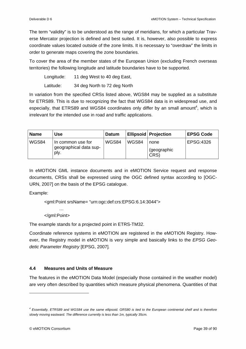
Deliverable D 6 eMOTION System – Technical Specification
© eMOTION Consortium Page 39 of 90
The term “validity” is to be understood as the range of meridians, for which a particular Trav-erse Mercator projection is defined and best suited. It is, however, also possible to express coordinate values located outside of the zone limits. It is necessary to “overdraw” the limits in order to generate maps covering the zone boundaries.
To cover the area of the member states of the European Union (excluding French overseas territories) the following longitude and latitude boundaries have to be supported.
Longitude: 11 deg West to 40 deg East,
Latitude: 34 deg North to 72 deg North
In variation from the specified CRSs listed above, WGS84 may be supplied as a substitute for ETRS89. This is due to recognizing the fact that WGS84 data is in widespread use, and especially, that ETRS89 and WGS84 coordinates only differ by an small amount4, which is irrelevant for the intended use in road and traffic applications.
Name Use Datum Ellipsoid Projection EPSG Code WGS84 In common use for
geographical data sup-ply.
WGS84 WGS84 none
(geographic CRS)
EPSG:4326
In eMOTION GML instance documents and in eMOTION Service request and response documents, CRSs shall be expressed using the OGC defined syntax according to [OGC-URN, 2007] on the basis of the EPSG catalogue.
Example:
<gml:Point srsName= “urn:ogc:def:crs:EPSG:6.14:3044”> … </gml:Point>
The example stands for a projected point in ETRS-TM32.
Coordinate reference systems in eMOTION are registered in the eMOTION Registry. How-ever, the Registry model in eMOTION is very simple and basically links to the EPSG Geo-detic Parameter Registry [EPSG, 2007].
4.4 Measures and Units of Measure
The features in the eMOTION Data Model (especially those contained in the weather model) are very often described by quantities which measure physical phenomena. Quantities of that
4 Essentially, ETRS89 and WGS84 use the same ellipsoid. GRS80 is tied to the European continental shelf and is therefore slowly moving eastward. The difference currently is less than 1m, typically 35cm.
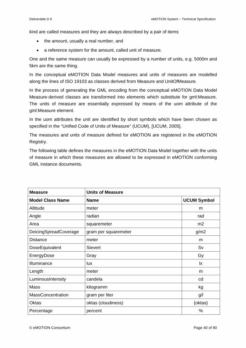
Deliverable D 6 eMOTION System – Technical Specification
© eMOTION Consortium Page 40 of 90
kind are called measures and they are always described by a pair of items
• the amount, usually a real number, and
• a reference system for the amount, called unit of measure.
One and the same measure can usually be expressed by a number of units, e.g. 5000m and 5km are the same thing.
In the conceptual eMOTION Data Model measures and units of measures are modelled along the lines of ISO 19103 as classes derived from Measure and UnitOfMeasure.
In the process of generating the GML encoding from the conceptual eMOTION Data Model Measure-derived classes are transformed into elements which substitute for gml:Measure. The units of measure are essentially expressed by means of the uom attribute of the gml:Measure element.
In the uom attributes the unit are identified by short symbols which have been chosen as specified in the “Unified Code of Units of Measure" (UCUM), [UCUM, 2005].
The measures and units of measure defined for eMOTION are registered in the eMOTION Registry.
The following table defines the measures in the eMOTION Data Model together with the units of measure in which these measures are allowed to be expressed in eMOTION conforming GML instance documents.
Measure Units of Measure
Model Class Name Name UCUM Symbol Altitude meter m
Angle radian rad
Area squaremeter m2
DeicingSpreadCoverage gram per squaremeter g/m2
Distance meter m
DoseEquivalent Sievert Sv
EnergyDose Gray Gy
Illuminance lux lx
Length meter m
LuminousIntensity candela cd
Mass kilogramm kg
MassConcentration gram per liter g/l
Oktas oktas (cloudiness) {oktas}
Percentage percent %
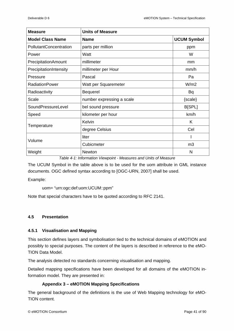
Deliverable D 6 eMOTION System – Technical Specification
© eMOTION Consortium Page 41 of 90
Measure Units of Measure
Model Class Name Name UCUM Symbol PollutantConcentration parts per million ppm
Power Watt W
PrecipitationAmount millimeter mm
PrecipitationIntensity millimeter per Hour mm/h
Pressure Pascal Pa
RadiationPower Watt per Squaremeter W/m2
Radioactivity Bequerel Bq
Scale number expressing a scale {scale}
SoundPressureLevel bel sound pressure B[SPL]
Speed kilometer per hour km/h
Kelvin K Temperature
degree Celsius Cel
liter l Volume
Cubicmeter m3
Weight Newton N Table 4-1: Information Viewpoint - Measures and Units of Measure
The UCUM Symbol in the table above is to be used for the uom attribute in GML instance documents. OGC defined syntax according to [OGC-URN, 2007] shall be used.
Example:
uom= “urn:ogc:def:uom:UCUM::ppm”
Note that special characters have to be quoted according to RFC 2141.
4.5 Presentation
4.5.1 Visualisation and Mapping
This section defines layers and symbolisation tied to the technical domains of eMOTION and possibly to special purposes. The content of the layers is described in reference to the eMO-TION Data Model.
The analysis detected no standards concerning visualisation and mapping.
Detailed mapping specifications have been developed for all domains of the eMOTION in-formation model. They are presented in:
Appendix 3 – eMOTION Mapping Specifications
The general background of the definitions is the use of Web Mapping technology for eMO-TION content.
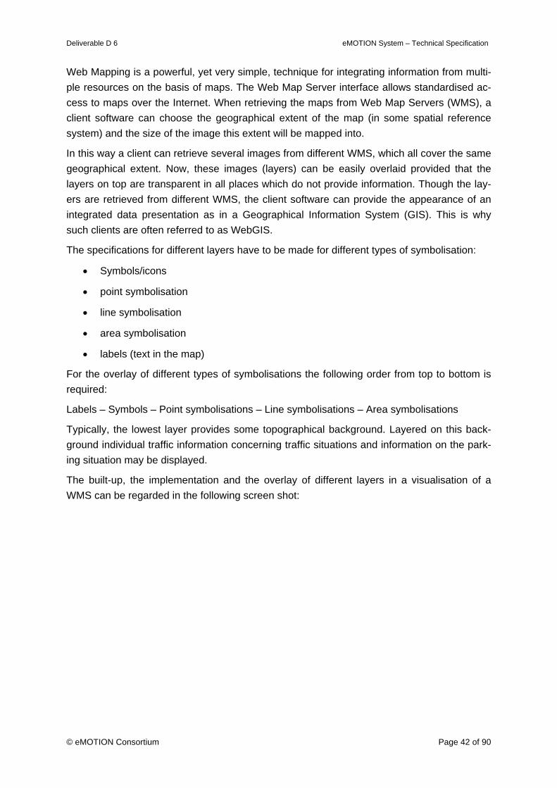
Deliverable D 6 eMOTION System – Technical Specification
© eMOTION Consortium Page 42 of 90
Web Mapping is a powerful, yet very simple, technique for integrating information from multi-ple resources on the basis of maps. The Web Map Server interface allows standardised ac-cess to maps over the Internet. When retrieving the maps from Web Map Servers (WMS), a client software can choose the geographical extent of the map (in some spatial reference system) and the size of the image this extent will be mapped into.
In this way a client can retrieve several images from different WMS, which all cover the same geographical extent. Now, these images (layers) can be easily overlaid provided that the layers on top are transparent in all places which do not provide information. Though the lay-ers are retrieved from different WMS, the client software can provide the appearance of an integrated data presentation as in a Geographical Information System (GIS). This is why such clients are often referred to as WebGIS.
The specifications for different layers have to be made for different types of symbolisation:
• Symbols/icons
• point symbolisation
• line symbolisation
• area symbolisation
• labels (text in the map)
For the overlay of different types of symbolisations the following order from top to bottom is required:
Labels – Symbols – Point symbolisations – Line symbolisations – Area symbolisations
Typically, the lowest layer provides some topographical background. Layered on this back-ground individual traffic information concerning traffic situations and information on the park-ing situation may be displayed.
The built-up, the implementation and the overlay of different layers in a visualisation of a WMS can be regarded in the following screen shot:
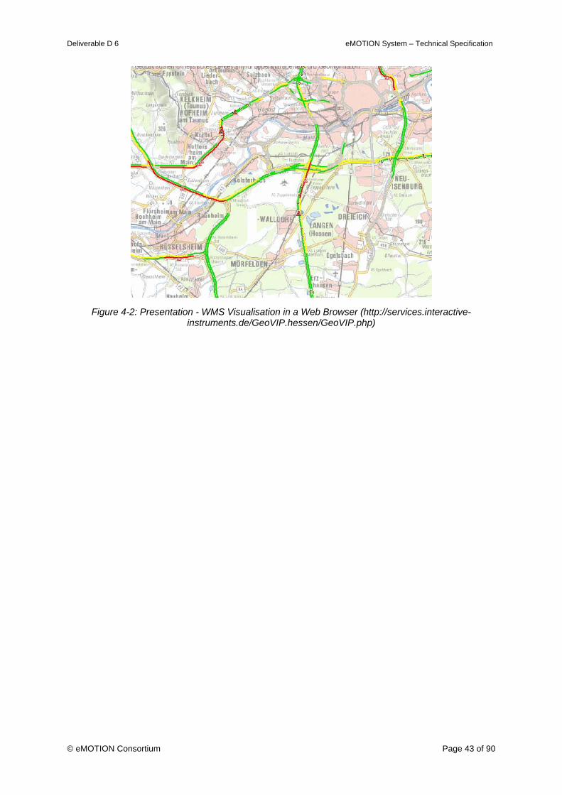
Deliverable D 6 eMOTION System – Technical Specification
© eMOTION Consortium Page 43 of 90
Figure 4-2: Presentation - WMS Visualisation in a Web Browser (http://services.interactive-
instruments.de/GeoVIP.hessen/GeoVIP.php)
Deliverable D 6 eMOTION System – Technical Specification
© eMOTION Consortium Page 44 of 90
5. Computational Viewpoint
This chapter is concerned with the functional decomposition of the system into a set of ob-jects that interact at interfaces.
5.1 eMOTION Encodings
5.1.1 Encodings for Data Exchange
As described in chapter 3.3 the exchange format for eMOTION data is defined by an Applica-tion Schema of Geography Markup Language (GML). The conceptual eMOTION Data Model is encoded in UML, and has been developed along the lines of the ISO 19100 Geographic Information Standards. With this it is possible to translate the eMOTION Data Model into a GML Application Schema, using the UML to GML Application Schema (UGAS) tool ShapeChange.
eMOTION Data Model - Overview
Features and data types of the different domains in the eMOTION Data Model are defined in individual Application Schemas. These Application Schemas are summarised in the central application schema EMotionData. The result of this organisation is a package structure as follows:
«Application Schema»EMotionData
+ CommonTypes+ Directories+ FixedInfrastructure+ JourneyPlanning+ LocationReference+ Network+ PublicTransport+ TrafficRelatedInformation+ Weather
(from TopLevel)
Figure 5-1: Encodings - eMOTION Data Model
Harmonising individual standards in the eMOTION Data Model leads to dependencies be-tween different Application Schemas, e.g. some features from PublicTransport are used in JourneyPlanning. Besides this, all Application Schemas contains types which are defined in the ISO 19100 series.
The dependencies in the eMOTION Data Model between packages which represent UML Application Schemas are shown in the following figure:
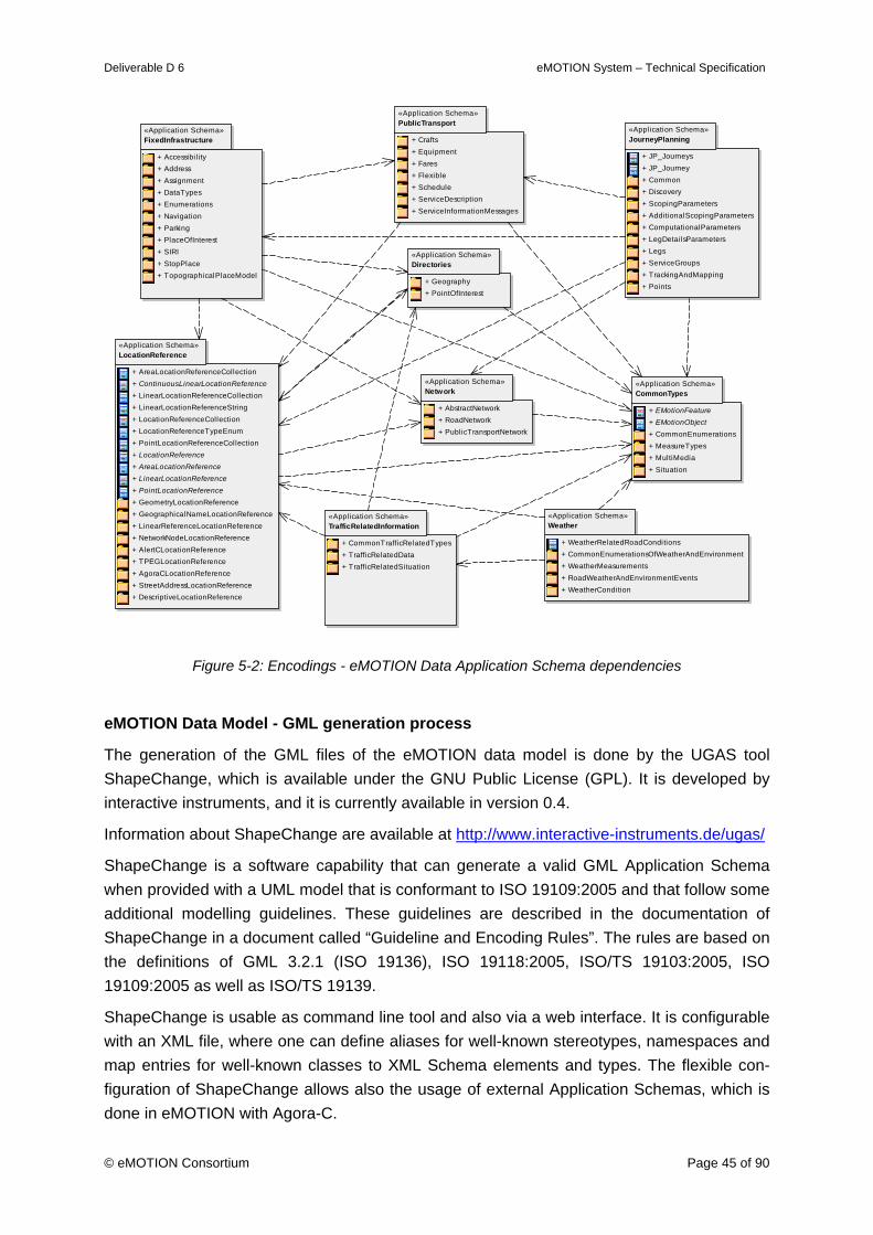
Deliverable D 6 eMOTION System – Technical Specification
© eMOTION Consortium Page 45 of 90
«Application Schema»Network
+ AbstractNetwork+ RoadNetwork+ PublicTransportNetwork
«Application Schema»Directories
+ Geography+ PointOfInterest
«Application Schema»LocationReference
+ AreaLocationReferenceCollection+ ContinuousLinearLocationReference+ LinearLocationReferenceCollection+ LinearLocationReferenceString+ LocationReferenceCollection+ LocationReferenceTypeEnum+ PointLocationReferenceCollection+ LocationReference+ AreaLocationReference+ LinearLocationReference+ PointLocationReference+ GeometryLocationReference+ GeographicalNameLocationReference+ LinearReferenceLocationReference+ NetworkNodeLocationReference+ AlertCLocationReference+ TPEGLocationReference+ AgoraCLocationReference+ StreetAddressLocationReference+ DescriptiveLocationReference
«Application Schema»CommonTypes
+ EMotionFeature+ EMotionObject+ CommonEnumerations+ MeasureTypes+ MultiMedia+ Situation
«Application Schema»TrafficRelatedInformation
+ CommonTrafficRelatedTypes+ TrafficRelatedData+ TrafficRelatedSituation
«Application Schema»Weather
+ WeatherRelatedRoadConditions+ CommonEnumerationsOfWeatherAndEnvironment+ WeatherMeasurements+ RoadWeatherAndEnvironmentEvents+ WeatherCondition
«Application Schema»FixedInfrastructure
+ Accessibi lity+ Address+ Assignment+ DataTypes+ Enumerations+ Navigation+ Parking+ PlaceOfInterest+ SIRI+ StopPlace+ TopographicalPlaceModel
«Application Schema»PublicTransport
+ Crafts+ Equipment+ Fares+ Flexible+ Schedule+ ServiceDescription+ ServiceInformationMessages
«Application Schema»JourneyPlanning
+ JP_Journeys+ JP_Journey+ Common+ Discovery+ ScopingParameters+ AdditionalScopingParameters+ ComputationalParameters+ LegDetailsParameters+ Legs+ ServiceGroups+ TrackingAndMapping+ Points
Figure 5-2: Encodings - eMOTION Data Application Schema dependencies
eMOTION Data Model - GML generation process
The generation of the GML files of the eMOTION data model is done by the UGAS tool ShapeChange, which is available under the GNU Public License (GPL). It is developed by interactive instruments, and it is currently available in version 0.4.
Information about ShapeChange are available at http://www.interactive-instruments.de/ugas/
ShapeChange is a software capability that can generate a valid GML Application Schema when provided with a UML model that is conformant to ISO 19109:2005 and that follow some additional modelling guidelines. These guidelines are described in the documentation of ShapeChange in a document called “Guideline and Encoding Rules”. The rules are based on the definitions of GML 3.2.1 (ISO 19136), ISO 19118:2005, ISO/TS 19103:2005, ISO 19109:2005 as well as ISO/TS 19139.
ShapeChange is usable as command line tool and also via a web interface. It is configurable with an XML file, where one can define aliases for well-known stereotypes, namespaces and map entries for well-known classes to XML Schema elements and types. The flexible con-figuration of ShapeChange allows also the usage of external Application Schemas, which is done in eMOTION with Agora-C.
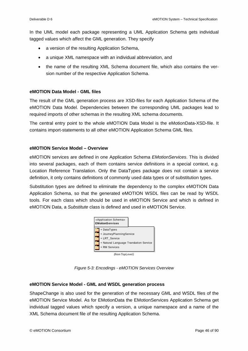
Deliverable D 6 eMOTION System – Technical Specification
© eMOTION Consortium Page 46 of 90
In the UML model each package representing a UML Application Schema gets individual tagged values which affect the GML generation. They specify
• a version of the resulting Application Schema,
• a unique XML namespace with an individual abbreviation, and
• the name of the resulting XML Schema document file, which also contains the ver-sion number of the respective Application Schema.
eMOTION Data Model - GML files
The result of the GML generation process are XSD-files for each Application Schema of the eMOTION Data Model. Dependencies between the corresponding UML packages lead to required imports of other schemas in the resulting XML schema documents.
The central entry point to the whole eMOTION Data Model is the eMotionData-XSD-file. It contains import-statements to all other eMOTION Application Schema GML files.
eMOTION Service Model – Overview
eMOTION services are defined in one Application Schema EMotionServices. This is divided into several packages, each of them contains service definitions in a special context, e.g. Location Reference Translation. Only the DataTypes package does not contain a service definition, it only contains definitions of commonly used data types or of substitution types.
Substitution types are defined to eliminate the dependency to the complex eMOTION Data Application Schema, so that the generated eMOTION WSDL files can be read by WSDL tools. For each class which should be used in eMOTION Service and which is defined in eMOTION Data, a Substitute class is defined and used in eMOTION Service.
«Application Schema»EMotionServ ices
+ DataTypes+ JourneyPlanningService+ LRT_Service+ Natural Language Translation Service+ RM Services
(from TopLevel)
Figure 5-3: Encodings - eMOTION Services Overview
eMOTION Service Model - GML and WSDL generation process
ShapeChange is also used for the generation of the necessary GML and WSDL files of the eMOTION Service Model. As for EMotionData the EMotionServices Application Schema get individual tagged values which specify a version, a unique namespace and a name of the XML Schema document file of the resulting Application Schema.
Deliverable D 6 eMOTION System – Technical Specification
© eMOTION Consortium Page 47 of 90
eMOTION Service Model - GML and WSDL files
ShapeChange generates one XSD-file for the EmotionService Application Schema, and a WSDL file for each service interface.
5.1.2 Encodings for Visual Information
In the eMOTION System visual information is created mainly in the form of image files, which are output by eMOTION Web Map Services5. Another use is the provision of images from camera systems, monitoring traffic or weather situations.
For these uses one of:
PNG (Portable Network Graphics), [PNG, 1997]
GIF (Graphics Interchance Format), [GIF, 1989]
shall be supported.
The GIF Format may be used for animated images producing time lap effects in order to visualize motion of weather phenomena.
Images, which do not require transparency (i.e. background maps) may also be represented in
JPEG (Joint Photographic Expert Group), [ISO 10918-1, 1994].
JPEG has a high compression rate, but produces a visible loss of quality in the compression processes.
5.1.3 Encodings for Coverage
Coverages as output by eMOTION Web Coverage Services6 shall be represented using
GeoTIFF (), [GeoTIFF, 2000].
5.1.4 Encodings for Multimedia and Audio Information
Mutlimedia-Encodings
5 Image data also appears as the primary data basis of meteorological information (in a coverage style use). This is of no con-cern here, because the processing of this data is outside of the scope of the eMOTION Technical Specification. 6 Meteorological coverages are typically represented using the BUFR standard. This representation, however, is of no concern here, because the processing of this data is outside of the scope of the eMOTION Technical Specification.

Deliverable D 6 eMOTION System – Technical Specification
© eMOTION Consortium Page 48 of 90
This chapter defines a guideline for the transport of digitally encoded Multimedia-data.
Currently, the eMOTION framework provides a rough guideline for the transport of digitally encoded audio- and video-information, since this is just a minor objective. More than that, international standardisation consortiums like the World Wide Web Consortium (W3C) are on their way to define such an open standard.
Due to this work, providing a complete Multimedia service would most likely cause serious disadvantages, such as lacking support for existing (currently evolving) standards, legacies and possible impracticalness. Because of this, the eMOTION framework was designed to be enhanced by these features in future versions, and currently only provides a recommenda-tion, based on reliable standards and recommendations existing so far.
Digitally encoded video data consists of the following basic parts:
- Content-Type information
- Container format
- Audio codec
- Video codec
All of these parts should fit to the following needs:
1. Available to the public – no specific licensing- or patent-restrictions, no special con-tracts required to use the technology.
2. Platform independence – the technology must not be restricted to one platform or the technology of one supplier. Methods to decode- and encode data must be available for all main software platforms in concern.
3. Watched over by an independent consortium – no company-internal standards, ISO/IEC standards and industrial standards preferred.
Recommended formats
Content-Type
For the identification of an Multimedia data stream, the RFC 2046 method, also known as MIME-Type must be used. This standard method to identify data allows the easy classifica-tion of data before it's transmission.
Container formats
The container-format is an often underestimated topic, especially when it comes to video-streaming. Responsible for the proper storage of audio-, video-, subtitle-, meta-data- and synchronization-information, a modern container has many capabilities. Native support for different languages (e.g. audio streams) and subtitles is a key factor.
Recommended container-formats:
Deliverable D 6 eMOTION System – Technical Specification
© eMOTION Consortium Page 49 of 90
1. MPEG-4 File format (ISO/IEC 14496-14), limited to several kinds of MPEG video, au-dio, subtitle and picture data, allows streaming of data, but lacks in support for con-tent meta-data (menus, etc.)
2. 3GPP (as in 3GPP TS 26.244, 3rd Generation Partnership Project) is an international industrial standard based on the MPEG-4 container, but has better support for differ-ent codecs. It is limited in it's technical capabilities due to the design focus on small- and handheld-devices.
3. Matroska, a binary-packed, streaming capable XML container format. Support for a virtually unlimited number of audio-, video- and subtitle streams, meta-data and meta-content. Matroska is a free format, several implementations are available for different software platforms. It is not an official ISO/IEC standard, but developed by an inde-pendent open group.
Audio formats
1. MPEG-4 Part 3 (AAC, ISO/IEC 14496-3), a modern high-performance audio-codec, successor of MP3.
2. MPEG-1 Audio Layer 3 (MP3, ISO/IEC 11172-3), is the most common encoding for digital audio.
3. Vorbis, unlike AAC and MP3 is not an ISO-Standard. It is free of charge, supports a large number of hard- and software-decoders, and is the codec-of-choice for many streaming media content providers.
Video formats
1. H.264 (MPEG-4/AVC, ISO/IEC 14496-10 and -2), state of the art codec for video data. H.264 is widely supported. It's major disadvantage is the still not fully clarified li-censing-policy. It's predecessor, the Part 3 standard, is implemented in codecs like Apple QuickTime, DivX and Xvid.
2. Theora (VP3.2), an open video codec with strong streaming capabilities. Like Vorbis, it will most likely be part of HTML 5 as core video codec.
5.2 eMOTION Service Interface Definition
The eMOTION Service Interface Definitions constitute an important part of the Technical Specification, comparable in importance to the eMOTION Data Model. The Service Interface Definitions make sure that the eMOTION system components can communicate on the basis of well-known interfaces.
Services have been specified in one of two ways.
1. wherever possible, existing service standards have been used, especially from OGC
Deliverable D 6 eMOTION System – Technical Specification
© eMOTION Consortium Page 50 of 90
and OASIS. In these cases profiles have been defined.
2. If appropriate existing service definitions were not available, eMOTION Services were specified in formal UML models. These models were then automatically translated into WSDL documents describing the interfaces.
See the eMOTION Model and
Appendix 2 – eMOTION Service Interface Definition
for a full specification of the eMOTION Services.
5.2.1 Data Services
One of the core tasks of eMOTION services is the provision of data according to the eMO-TION Data Model. Data from various sources has to be queried, combined, processed and made available to other services and end users.
Data Services constitute the eMOTION Services equivalent of databases. eMOTION Data Services obtain the information they are exposing from other Data Services or from hidden databases. For example, dynamic traffic related data is typically assembled from on-line sen-sor data sources or pre-processed data hand-overs from basic traffic management systems.
eMOTION Data Services are mainly based on the OGC Web Feature Service and the ac-companying Filter Encodings standard. eMOTION Data Services may also be realised by means of the OGC Web Coverage Service. Only some environmental and weather data is subject to this.
5.2.2 Mapping Services
Mapping Services deliver maps of the data. These maps are styled according to the eMO-TION Mapping Specifications described in Appendix 3.
Web Mapping is a powerful, yet very simple, technique for integrating information from multi-ple resources on the basis of maps. When retrieving maps from Web Map Servers (WMS), a client software can choose the geographical extent of the map (in some spatial reference system) and the size of the image this extent will be mapped into. In this way a client can retrieve several images from different WMS, which all cover the same geographical extent. Now, these images (layers) can be easily overlaid provided that the layers on top are trans-parent in all places, which do not provide information.
eMOTION Web Mapping Services are based on the OGC Web Map Server specification and the accompanying standards Styled Layer Descriptor and Symbology Encoding.
5.2.3 Event Notification Service
Services and applications can register with Event Notification Services and are called-back when certain events in the subscribed data or service occur.
Deliverable D 6 eMOTION System – Technical Specification
© eMOTION Consortium Page 51 of 90
The service model for handling event notifications is given by the OASIS WSN 1.3 standard. Notify messages are sent by the producer of the notification first to a Notification Broker ser-vice. This service keeps track of all subscriptions for notifications. Upon receipt of a notifica-tion it checks the set of subscriptions to determine which services should receive this notifi-cation and then relays it to the recipients.
eMOTION Services, which shall be original producers of notifications, have to be prepared to notify the Notification Broker to indicate some event – they have to be “notification-enabled”. All services or applications that shall be able to receive notification messages must expose a NotificationConsumer interface.
5.2.4 Inter-modal Journey Planners
Web Services for calculating Journeys are defined. A Journey is defined as a sequence of Journey parts (or Legs) that can be characterized by a specific mode (including car and walk). They are the result of a request for:
A departure from an origin point
An arrival to a destination point
Choice of Pass thought Waypoints
Choice of Points to avoid
Other options are given in preferences in terms of time (arrival, departure etc.), modes (pre-ferred, to exclude…) and other (cheapest, shortest, fastest route, presence of facilities etc.).
The specification describes two service interfaces:
1. A full eMOTION Inter-modal Journey Planning Service, which is able to execute a Journey Planning request with all the necessary input and output requirements. This service is also able to act as part of a hierarchical system of Journey Planners, where the results of other Journey Planners are combined to a larger plan.
2. A service definition with reduced capabilities, which constitutes a profile of the OGC OpenLS Route service, which is called eMOTION Inter-modal Journey Planning Ser-vice – LBS Profile. The definition lacks the ability to deal with combined plans.
5.2.5 Geo-Directory Services
These Services translate geographical names into coordinate or feature references. They also allow translation between street addresses and coordinates.
The term Directory Services has been coined in the world of Location Based Services, where those services make for retrieving Points of Interest (POIs) from adequate directories. Those directories are usually flat, like the Yellow Pages telephone directory.
The eMOTION Definition is mainly based on the OGC Gazetteer profile of Web Feature Ser-vice. It can represent a hierarchical structure of objects.
Deliverable D 6 eMOTION System – Technical Specification
© eMOTION Consortium Page 52 of 90
5.2.6 Reference Translation Services
Reference Translation Services mediate between different Location Reference styles.
These Services are fundamental to the architecture of eMOTION, because they unburden all other services from the necessity of supporting these translations.
Additional specialised service definitions, which also are part of this specification are:
• Geocoders, Reverse Geocoders, which translate between street addresses and point locations and
• Coordinate Transformation Services, which translate between different coordinate reference systems.
5.2.7 Positioning Services
Positioning Services make available the positions of mobile users over a web interface. Dif-ferent telecommunication means can be applied to implement the interface.
The specification is based on the OGC OpenLS Gateway interface.
5.2.8 Registry Services
A registry service is a centralised place into which metadata for content and services is placed. It can be used to find and evaluate the usefulness of resources, but may also contain metadata necessary for the use of a resource.
The eMOTION Registry Service is defined to be an implementation of the OASIS ebXML Registry Service (ebRS) together with its Registry Information Model (ebRIM).
Appendix 4 specifies the Registry Information Model for eMOTION.
5.2.9 Rights Management Services
Rights Management Services encompass a variety of services for assigning identity to users and controlling access to resources.
A collection of auxiliary services is defined, which provides security in using the eMOTION services proper, such as eMOTION Data Services, Mapping Services, Journey Planning Services, etc. Security means that: Only actors so authorised may use such a service re-source as a whole or part of its resources. Typical resources are: Individual features, feature types, layers, etc.
The service interfaces are constructed along the lines of GeoDRM RM. Standards are em-ployed wherever possible.
The information model for eMOTION rights management is based on the OASIS XACML standard, its proposed extension for geospatial data (in short: GeoXACML) and the applica-tion of security standards to rights management for geospatial data in a way close to, but not identical to the work described in the OGC GeoDRM Reference Model.
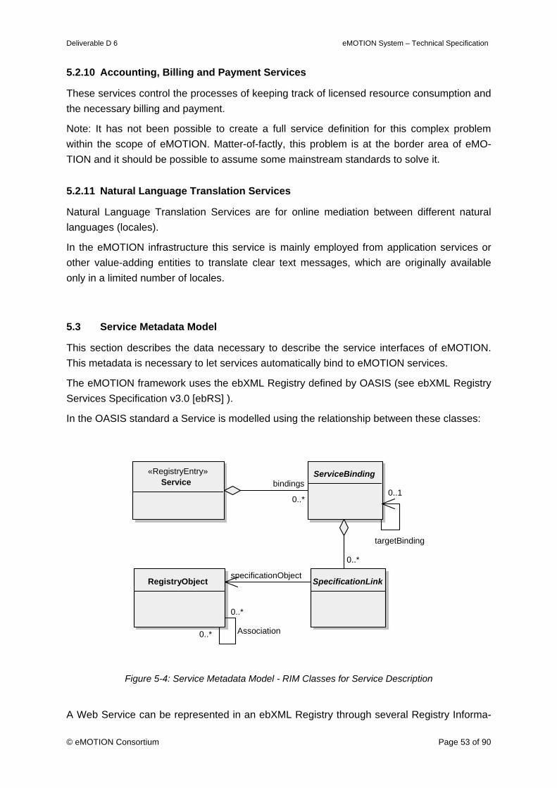
Deliverable D 6 eMOTION System – Technical Specification
© eMOTION Consortium Page 53 of 90
5.2.10 Accounting, Billing and Payment Services
These services control the processes of keeping track of licensed resource consumption and the necessary billing and payment.
Note: It has not been possible to create a full service definition for this complex problem within the scope of eMOTION. Matter-of-factly, this problem is at the border area of eMO-TION and it should be possible to assume some mainstream standards to solve it.
5.2.11 Natural Language Translation Services
Natural Language Translation Services are for online mediation between different natural languages (locales).
In the eMOTION infrastructure this service is mainly employed from application services or other value-adding entities to translate clear text messages, which are originally available only in a limited number of locales.
5.3 Service Metadata Model
This section describes the data necessary to describe the service interfaces of eMOTION. This metadata is necessary to let services automatically bind to eMOTION services.
The eMOTION framework uses the ebXML Registry defined by OASIS (see ebXML Registry Services Specification v3.0 [ebRS] ).
In the OASIS standard a Service is modelled using the relationship between these classes:
ServiceBinding
SpecificationLink
«RegistryEntry» Service
RegistryObject
0..*
bindings
0..*
specificationObject
targetBinding
0..1
0..* Association
0..*
Figure 5-4: Service Metadata Model - RIM Classes for Service Description
A Web Service can be represented in an ebXML Registry through several Registry Informa-
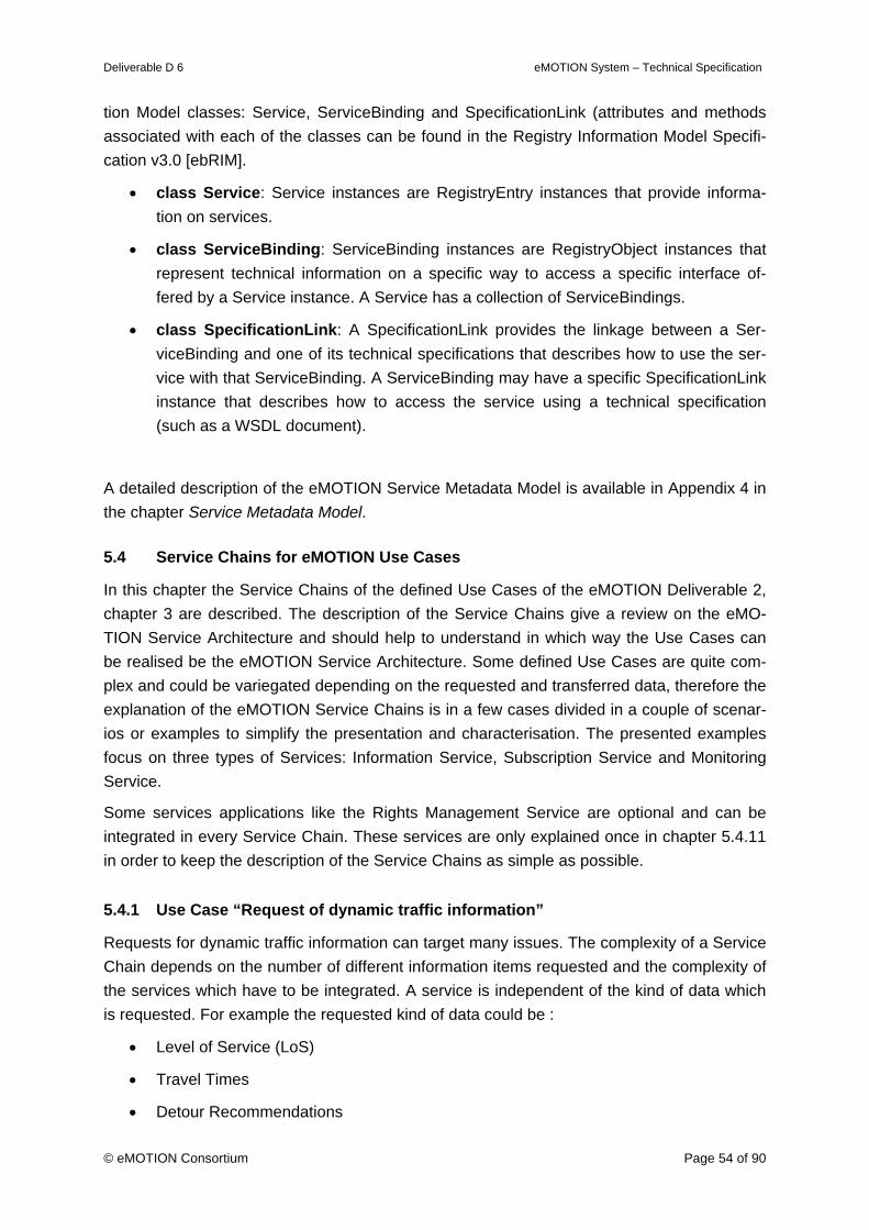
Deliverable D 6 eMOTION System – Technical Specification
© eMOTION Consortium Page 54 of 90
tion Model classes: Service, ServiceBinding and SpecificationLink (attributes and methods associated with each of the classes can be found in the Registry Information Model Specifi-cation v3.0 [ebRIM].
• class Service: Service instances are RegistryEntry instances that provide informa-tion on services.
• class ServiceBinding: ServiceBinding instances are RegistryObject instances that represent technical information on a specific way to access a specific interface of-fered by a Service instance. A Service has a collection of ServiceBindings.
• class SpecificationLink: A SpecificationLink provides the linkage between a Ser-viceBinding and one of its technical specifications that describes how to use the ser-vice with that ServiceBinding. A ServiceBinding may have a specific SpecificationLink instance that describes how to access the service using a technical specification (such as a WSDL document).
A detailed description of the eMOTION Service Metadata Model is available in Appendix 4 in the chapter Service Metadata Model.
5.4 Service Chains for eMOTION Use Cases
In this chapter the Service Chains of the defined Use Cases of the eMOTION Deliverable 2, chapter 3 are described. The description of the Service Chains give a review on the eMO-TION Service Architecture and should help to understand in which way the Use Cases can be realised be the eMOTION Service Architecture. Some defined Use Cases are quite com-plex and could be variegated depending on the requested and transferred data, therefore the explanation of the eMOTION Service Chains is in a few cases divided in a couple of scenar-ios or examples to simplify the presentation and characterisation. The presented examples focus on three types of Services: Information Service, Subscription Service and Monitoring Service.
Some services applications like the Rights Management Service are optional and can be integrated in every Service Chain. These services are only explained once in chapter 5.4.11 in order to keep the description of the Service Chains as simple as possible.
5.4.1 Use Case “Request of dynamic traffic information”
Requests for dynamic traffic information can target many issues. The complexity of a Service Chain depends on the number of different information items requested and the complexity of the services which have to be integrated. A service is independent of the kind of data which is requested. For example the requested kind of data could be :
• Level of Service (LoS)
• Travel Times
• Detour Recommendations
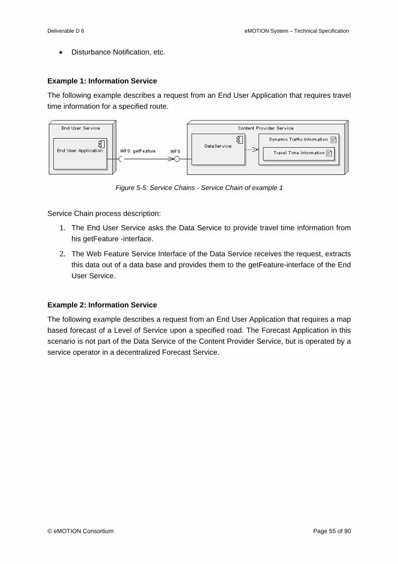
Deliverable D 6 eMOTION System – Technical Specification
© eMOTION Consortium Page 55 of 90
• Disturbance Notification, etc.
Example 1: Information Service
The following example describes a request from an End User Application that requires travel time information for a specified route.
Figure 5-5: Service Chains - Service Chain of example 1
Service Chain process description:
1. The End User Service asks the Data Service to provide travel time information from his getFeature -interface.
2. The Web Feature Service Interface of the Data Service receives the request, extracts this data out of a data base and provides them to the getFeature-interface of the End User Service.
Example 2: Information Service
The following example describes a request from an End User Application that requires a map based forecast of a Level of Service upon a specified road. The Forecast Application in this scenario is not part of the Data Service of the Content Provider Service, but is operated by a service operator in a decentralized Forecast Service.
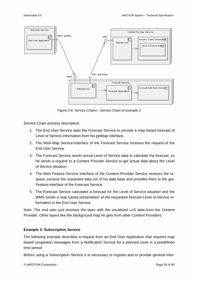
Deliverable D 6 eMOTION System – Technical Specification
© eMOTION Consortium Page 56 of 90
Figure 5-6: Service Chains - Service Chain of example 2
Service Chain process description:
1. The End User Service asks the Forecast Service to provide a map based forecast of Level of Service information from his getMap interface.
2. The Web Map Service-Interface of the Forecast Service receives the request of the End User Service.
3. The Forecast Service needs actual Level of Service data to calculate the forecast, so he sends a request to a Content Provider Service to get actual data about the Level of Service situation.
4. The Web Feature Service Interface of the Content Provider Service receives the re-quest, extracts the requested data out of his data base and provides them to the get-Feature-interface of the Forecast Service.
5. The Forecast Service calculates a forecast for the Level of Service situation and the WMS sends a map based presentation of the requested forecast Level of Service in-formation to the End User Service.
Note: The end user just receives the layer with the visualised LoS data from the Content Provider. Other layers like the background map he gets from other Content Providers.
Example 3: Subscription Service
The following example describes a request from an End User Application that requires map based congestion messages from a Notification Service for a planned route in a predefined time period.
Before using a Subscription Service it is necessary to register and to provide general infor-
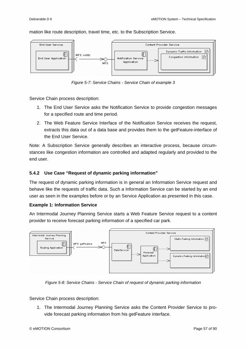
Deliverable D 6 eMOTION System – Technical Specification
© eMOTION Consortium Page 57 of 90
mation like route description, travel time, etc. to the Subscription Service.
Figure 5-7: Service Chains - Service Chain of example 3
Service Chain process description:
1. The End User Service asks the Notification Service to provide congestion messages for a specified route and time period.
2. The Web Feature Service Interface of the Notification Service receives the request, extracts this data out of a data base and provides them to the getFeature-interface of the End User Service.
Note: A Subscription Service generally describes an interactive process, because circum-stances like congestion information are controlled and adapted regularly and provided to the end user.
5.4.2 Use Case “Request of dynamic parking information”
The request of dynamic parking information is in general an Information Service request and behave like the requests of traffic data. Such a Information Service can be started by an end user as seen in the examples before or by an Service Application as presented in this case.
Example 1: Information Service
An Intermodal Journey Planning Service starts a Web Feature Service request to a content provider to receive forecast parking information of a specified car park.
Figure 5-8: Service Chains - Service Chain of request of dynamic parking information
Service Chain process description:
1. The Intermodal Journey Planning Service asks the Content Provider Service to pro-vide forecast parking information from his getFeature interface.
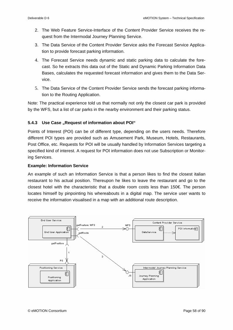
Deliverable D 6 eMOTION System – Technical Specification
© eMOTION Consortium Page 58 of 90
2. The Web Feature Service-Interface of the Content Provider Service receives the re-quest from the Intermodal Journey Planning Service.
3. The Data Service of the Content Provider Service asks the Forecast Service Applica-tion to provide forecast parking information.
4. The Forecast Service needs dynamic and static parking data to calculate the fore-cast. So he extracts this data out of the Static and Dynamic Parking Information Data Bases, calculates the requested forecast information and gives them to the Data Ser-vice.
5. The Data Service of the Content Provider Service sends the forecast parking informa-tion to the Routing Application.
Note: The practical experience told us that normally not only the closest car park is provided by the WFS, but a list of car parks in the nearby environment and their parking status.
5.4.3 Use Case „Request of information about POI“
Points of Interest (POI) can be of different type, depending on the users needs. Therefore different POI types are provided such as Amusement Park, Museum, Hotels, Restaurants, Post Office, etc. Requests for POI will be usually handled by Information Services targeting a specified kind of interest. A request for POI information does not use Subscription or Monitor-ing Services.
Example: Information Service
An example of such an Information Service is that a person likes to find the closest italian restaurant to his actual position. Thereupon he likes to leave the restaurant and go to the closest hotel with the characteristic that a double room costs less than 150€. The person locates himself by pinpointing his whereabouts in a digital map. The service user wants to receive the information visualised in a map with an additional route description.
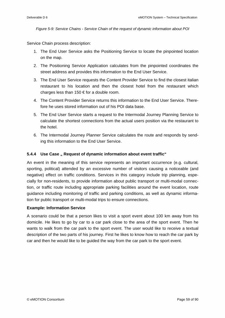
Deliverable D 6 eMOTION System – Technical Specification
© eMOTION Consortium Page 59 of 90
Figure 5-9: Service Chains - Service Chain of the request of dynamic information about POI
Service Chain process description:
1. The End User Service asks the Positioning Service to locate the pinpointed location on the map.
2. The Positioning Service Application calculates from the pinpointed coordinates the street address and provides this information to the End User Service.
3. The End User Service requests the Content Provider Service to find the closest italian restaurant to his location and then the closest hotel from the restaurant which charges less than 150 € for a double room.
4. The Content Provider Service returns this information to the End User Service. There-fore he uses stored information out of his POI data base.
5. The End User Service starts a request to the Intermodal Journey Planning Service to calculate the shortest connections from the actual users position via the restaurant to the hotel.
6. The Intermodal Journey Planner Service calculates the route and responds by send-ing this information to the End User Service.
5.4.4 Use Case „ Request of dynamic information about event traffic“
An event in the meaning of this service represents an important occurrence (e.g. cultural, sporting, political) attended by an excessive number of visitors causing a noticeable (and negative) effect on traffic conditions. Services in this category include trip planning, espe-cially for non-residents, to provide information about public transport or multi-modal connec-tion, or traffic route including appropriate parking facilities around the event location, route guidance including monitoring of traffic and parking conditions, as well as dynamic informa-tion for public transport or multi-modal trips to ensure connections.
Example: Information Service
A scenario could be that a person likes to visit a sport event about 100 km away from his domicile. He likes to go by car to a car park close to the area of the sport event. Then he wants to walk from the car park to the sport event. The user would like to receive a textual description of the two parts of his journey. First he likes to know how to reach the car park by car and then he would like to be guided the way from the car park to the sport event.
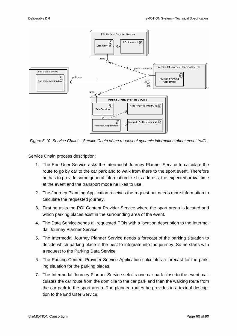
Deliverable D 6 eMOTION System – Technical Specification
© eMOTION Consortium Page 60 of 90
Figure 5-10: Service Chains - Service Chain of the request of dynamic information about event traffic
Service Chain process description:
1. The End User Service asks the Intermodal Journey Planner Service to calculate the route to go by car to the car park and to walk from there to the sport event. Therefore he has to provide some general information like his address, the expected arrival time at the event and the transport mode he likes to use.
2. The Journey Planning Application receives the request but needs more information to calculate the requested journey.
3. First he asks the POI Content Provider Service where the sport arena is located and which parking places exist in the surrounding area of the event.
4. The Data Service sends all requested POIs with a location description to the Intermo-dal Journey Planner Service.
5. The Intermodal Journey Planner Service needs a forecast of the parking situation to decide which parking place is the best to integrate into the journey. So he starts with a request to the Parking Data Service.
6. The Parking Content Provider Service Application calculates a forecast for the park-ing situation for the parking places.
7. The Intermodal Journey Planner Service selects one car park close to the event, cal-culates the car route from the domicile to the car park and then the walking route from the car park to the sport arena. The planned routes he provides in a textual descrip-tion to the End User Service.
Deliverable D 6 eMOTION System – Technical Specification
© eMOTION Consortium Page 61 of 90
5.4.5 Use Case „Request of dynamic information about public transport“
Information about public transport could be of interest in a lot of cases. A user could be inter-ested in arrival times and departure times of transport modes, delayed journeys, cancelled trips, etc. This Service should be use to get dynamic public transport event information.
Example: Subscription Service
An example of an information about public transport could be a request to get delay informa-tion of a train. This information could be sent by SMS to a mobile phone of the passenger by a notification service. Before using the Subscription Service it is necessary to register and to provide general information like the train number, the name of the train station, etc. to the Subscription Service.
Figure 5-11: Service Chains - Service Chain of the request of dynamic information about public trans-
port
Service Chain process description:
1. The End User Service asks the Notification Service Application to inform him if the train he would like to travel with is delayed.
2. In this case the Notification Service Application gets information from the Public Transport Information data base and sends the message by SMS to the users mobile phone.
Note: A Subscription Service generally describes an interactive process, because circum-stances are controlled and adapted regularly and provided to the end user.
5.4.6 Use Case „Request of dynamic information about weather”
Dynamic information about weather in most cases covers common weather data like tem-perature or wind direction/wind speed for regional areas, road traffic related weather mes-sages and warnings like fog, ice and heavy rain. This kind of information shall improve road safety and can affect driver’s decision of route choice, departure time, stopovers, etc. Infor-mation should be provided to users to notify if awkward weather conditions have to be ex-pected on the road ahead or at any part of the whole route.
Weather content and row data can be provided by common weather services or by the road operators (or their service operators) derived from a road weather information system (RWIS) that is used for traffic control issues. A road weather information system can be de-fined as a combination of technologies that uses historic and current climate data to develop road and weather information (for example, now casts and forecasts) to aid in roadway-
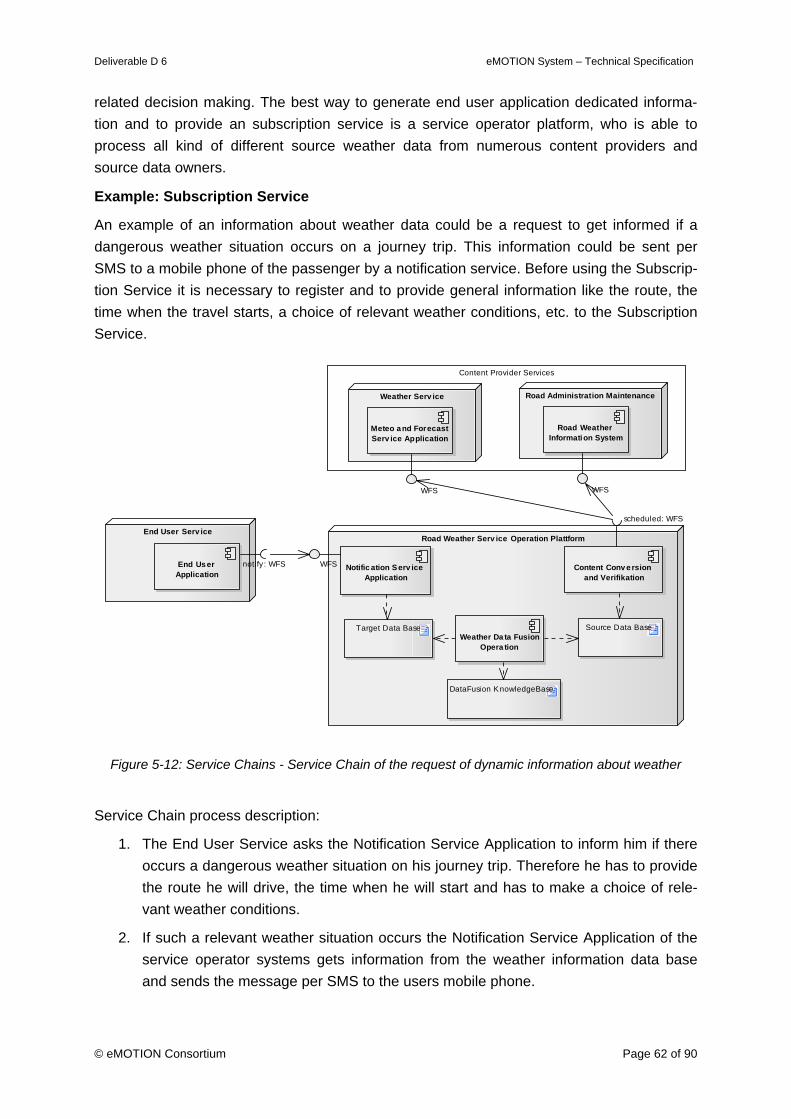
Deliverable D 6 eMOTION System – Technical Specification
© eMOTION Consortium Page 62 of 90
related decision making. The best way to generate end user application dedicated informa-tion and to provide an subscription service is a service operator platform, who is able to process all kind of different source weather data from numerous content providers and source data owners.
Example: Subscription Service
An example of an information about weather data could be a request to get informed if a dangerous weather situation occurs on a journey trip. This information could be sent per SMS to a mobile phone of the passenger by a notification service. Before using the Subscrip-tion Service it is necessary to register and to provide general information like the route, the time when the travel starts, a choice of relevant weather conditions, etc. to the Subscription Service.
Content Provider Services
End User Serv ice
End User Application
notify: WFS
Weather Serv ice Road Administration Maintenance
Road Weather Information System
WFS
Meteo and Forecast Serv ice Application
WFS
Road Weather Serv ice Operation Plattform
Content Conv ersion and Verifikation
scheduled: WFS
Notific ation Serv ice Application
WFS
Weather Da ta Fusion Opera tion
DataFusion KnowledgeBase
Source Data BaseTarget Data Base
Figure 5-12: Service Chains - Service Chain of the request of dynamic information about weather
Service Chain process description:
1. The End User Service asks the Notification Service Application to inform him if there occurs a dangerous weather situation on his journey trip. Therefore he has to provide the route he will drive, the time when he will start and has to make a choice of rele-vant weather conditions.
2. If such a relevant weather situation occurs the Notification Service Application of the service operator systems gets information from the weather information data base and sends the message per SMS to the users mobile phone.
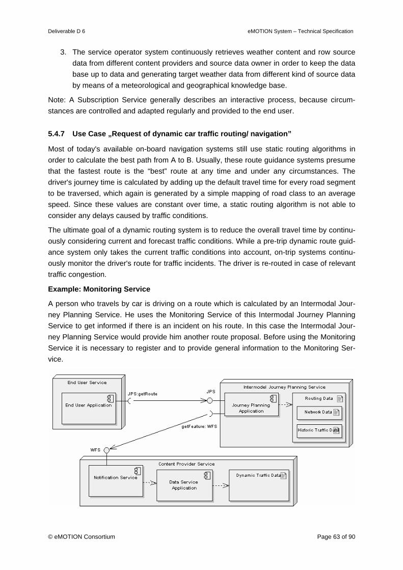
Deliverable D 6 eMOTION System – Technical Specification
© eMOTION Consortium Page 63 of 90
3. The service operator system continuously retrieves weather content and row source data from different content providers and source data owner in order to keep the data base up to data and generating target weather data from different kind of source data by means of a meteorological and geographical knowledge base.
Note: A Subscription Service generally describes an interactive process, because circum-stances are controlled and adapted regularly and provided to the end user.
5.4.7 Use Case „Request of dynamic car traffic routing/ navigation”
Most of today's available on-board navigation systems still use static routing algorithms in order to calculate the best path from A to B. Usually, these route guidance systems presume that the fastest route is the “best” route at any time and under any circumstances. The driver's journey time is calculated by adding up the default travel time for every road segment to be traversed, which again is generated by a simple mapping of road class to an average speed. Since these values are constant over time, a static routing algorithm is not able to consider any delays caused by traffic conditions.
The ultimate goal of a dynamic routing system is to reduce the overall travel time by continu-ously considering current and forecast traffic conditions. While a pre-trip dynamic route guid-ance system only takes the current traffic conditions into account, on-trip systems continu-ously monitor the driver's route for traffic incidents. The driver is re-routed in case of relevant traffic congestion.
Example: Monitoring Service
A person who travels by car is driving on a route which is calculated by an Intermodal Jour-ney Planning Service. He uses the Monitoring Service of this Intermodal Journey Planning Service to get informed if there is an incident on his route. In this case the Intermodal Jour-ney Planning Service would provide him another route proposal. Before using the Monitoring Service it is necessary to register and to provide general information to the Monitoring Ser-vice.
Deliverable D 6 eMOTION System – Technical Specification
© eMOTION Consortium Page 64 of 90
Figure 5-13: Service Chains - Service Chain of the request of dynamic car traffic routing/navigation
Service Chain process description:
1. The End User Service asks the Intermodal Route Planner Service to present him a route planning in a textual description. The following information is required from the user for a successful request of dynamic car traffic routing:
• Origin of the route (unless automatically detected by GPS)
• Destination of the route
• Possible stopover locations
• Preferred or excluded road types
• Type of route: fastest, shortest, most economic
• Vehicle characteristics (e.g. fast or slow car)
2. The Intermodal Route Planner Service receives the request, but the Route Planning Application needs static and dynamic traffic data to calculate the requested route.
3. The Route Planning Application asks a Content Provider Service to provide him ac-tual, dynamic traffic data for defined road segments.
4. The Content Provider Service sends the required dynamic traffic data to the Intermo-dal Route Planning Application.
5. The Intermodal Route Planning Application calculates the route by using network data, historic traffic data and dynamic traffic data.
6. The Intermodal Route Planning Application provides the route description in a textual form to the end user.
7. If a traffic situation such as a traffic jam, etc. occurs on the calculated route the Notifi-cation Service of the Content Provider Service sends this information to the Intermo-dal Route Planning Application, which calculates a new route for the user and sends the newest information directly to the end user.
Note: A Monitoring Service generally describes an interactive process, because circum-stances are controlled and adapted regularly and provided to the end user.
5.4.8 Use Case „Request of dynamic public transport journey planning”
Public transport journey planning is usually done before travelling at a point in time when actual conditions of the service during the expected journey are still unknown. In that case journey planning considers only static timetables for the information generation. Once a transport chain for a given departure and arrival time is requested there is usually no further service monitoring or correction made. This kind of request is to be handled by an informa-tion service. More advanced systems could also continuously monitor lines involved in the actual transport chain in order to alert the user if delays or cancellations occur. This kind of
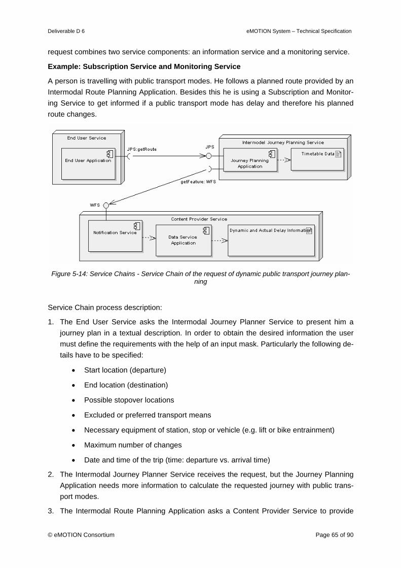
Deliverable D 6 eMOTION System – Technical Specification
© eMOTION Consortium Page 65 of 90
request combines two service components: an information service and a monitoring service.
Example: Subscription Service and Monitoring Service
A person is travelling with public transport modes. He follows a planned route provided by an Intermodal Route Planning Application. Besides this he is using a Subscription and Monitor-ing Service to get informed if a public transport mode has delay and therefore his planned route changes.
Figure 5-14: Service Chains - Service Chain of the request of dynamic public transport journey plan-
ning
Service Chain process description:
1. The End User Service asks the Intermodal Journey Planner Service to present him a journey plan in a textual description. In order to obtain the desired information the user must define the requirements with the help of an input mask. Particularly the following de-tails have to be specified:
• Start location (departure)
• End location (destination)
• Possible stopover locations
• Excluded or preferred transport means
• Necessary equipment of station, stop or vehicle (e.g. lift or bike entrainment)
• Maximum number of changes
• Date and time of the trip (time: departure vs. arrival time)
2. The Intermodal Journey Planner Service receives the request, but the Journey Planning Application needs more information to calculate the requested journey with public trans-port modes.
3. The Intermodal Route Planning Application asks a Content Provider Service to provide
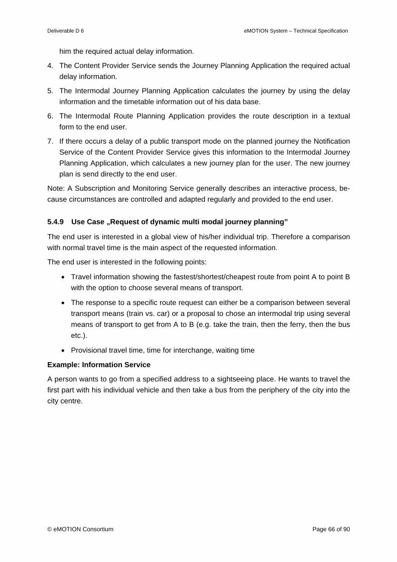
Deliverable D 6 eMOTION System – Technical Specification
© eMOTION Consortium Page 66 of 90
him the required actual delay information.
4. The Content Provider Service sends the Journey Planning Application the required actual delay information.
5. The Intermodal Journey Planning Application calculates the journey by using the delay information and the timetable information out of his data base.
6. The Intermodal Route Planning Application provides the route description in a textual form to the end user.
7. If there occurs a delay of a public transport mode on the planned journey the Notification Service of the Content Provider Service gives this information to the Intermodal Journey Planning Application, which calculates a new journey plan for the user. The new journey plan is send directly to the end user.
Note: A Subscription and Monitoring Service generally describes an interactive process, be-cause circumstances are controlled and adapted regularly and provided to the end user.
5.4.9 Use Case „Request of dynamic multi modal journey planning”
The end user is interested in a global view of his/her individual trip. Therefore a comparison with normal travel time is the main aspect of the requested information.
The end user is interested in the following points:
• Travel information showing the fastest/shortest/cheapest route from point A to point B with the option to choose several means of transport.
• The response to a specific route request can either be a comparison between several transport means (train vs. car) or a proposal to chose an intermodal trip using several means of transport to get from A to B (e.g. take the train, then the ferry, then the bus etc.).
• Provisional travel time, time for interchange, waiting time
Example: Information Service
A person wants to go from a specified address to a sightseeing place. He wants to travel the first part with his individual vehicle and then take a bus from the periphery of the city into the city centre.
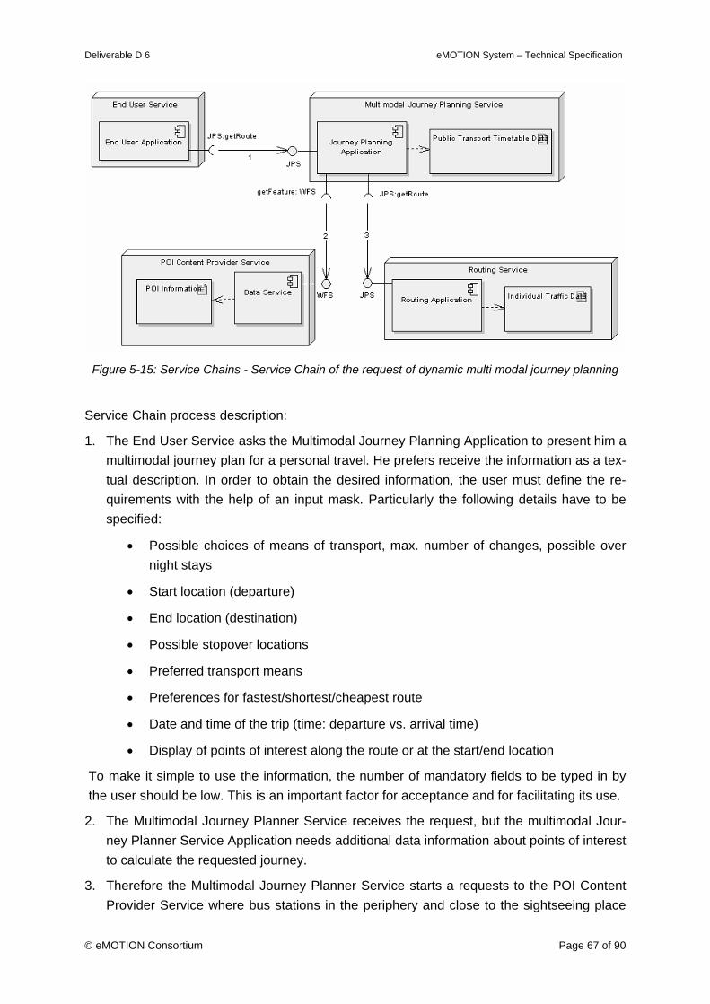
Deliverable D 6 eMOTION System – Technical Specification
© eMOTION Consortium Page 67 of 90
Figure 5-15: Service Chains - Service Chain of the request of dynamic multi modal journey planning
Service Chain process description:
1. The End User Service asks the Multimodal Journey Planning Application to present him a multimodal journey plan for a personal travel. He prefers receive the information as a tex-tual description. In order to obtain the desired information, the user must define the re-quirements with the help of an input mask. Particularly the following details have to be specified:
• Possible choices of means of transport, max. number of changes, possible over night stays
• Start location (departure)
• End location (destination)
• Possible stopover locations
• Preferred transport means
• Preferences for fastest/shortest/cheapest route
• Date and time of the trip (time: departure vs. arrival time)
• Display of points of interest along the route or at the start/end location
To make it simple to use the information, the number of mandatory fields to be typed in by the user should be low. This is an important factor for acceptance and for facilitating its use.
2. The Multimodal Journey Planner Service receives the request, but the multimodal Jour-ney Planner Service Application needs additional data information about points of interest to calculate the requested journey.
3. Therefore the Multimodal Journey Planner Service starts a requests to the POI Content Provider Service where bus stations in the periphery and close to the sightseeing place

Deliverable D 6 eMOTION System – Technical Specification
© eMOTION Consortium Page 68 of 90
exist.
4. The the POI Content Provider Service provides this information to the Multimodal Jour-ney Planner Service.
5. Now the Multimodal Journey Planner Service starts a request to the Routing Service to calculate the best route to go with an individual vehicle from his location to the bus sta-tion in the periphery.
6. The Routing Service calculates the individual traffic route and provides the route to the Multimodal Journey Planner Service.
7. The Multimodal Journey Planner Service calculates the multimodal trip by using the pro-vided individual traffic route with the timetable information out of his Public Transport Timetable data base.
8. The multimodal Journey Planner Service sends the planned travel route for the multimo-dal journey in a textual description to the end user.
5.4.10 Use Case “Request of dynamic information for freight traffic”
Caused by the fact that dynamic information for road users affects individuals as well as truck drivers, for this kind of request all information provided to individual road users are rele-vant. The provided information contains extra details and may have different priority to those for car drivers. Therefore the information presentation may be different. It must not be forgot-ten that the decision maker and recipient of information might not be the driver. Information on traffic conditions might be supplied to centralised tour planning or Computerised Vehicle Routing and Scheduling system, or to delivery point operations (message ahead to readjust delivery times based on traffic conditions ahead which will alter estimated time of arrival).
Navigation is not necessarily based on the fastest route. Depending on business needs, it may be necessary to consider the lowest cost route which may be: the shortest distance route; the route with least journey time uncertainty; or the safest route (that with reduced risk of bridge strikes, avoiding urban areas and schools or other potential delay due to geometry and traffic). In addition to traditional navigation services, navigation services aimed at freight industries may include the ability to specify multiple drops and optimise the route between drop points.
For unfamiliar drivers, particularly when involved in multiple-drops and home delivery opera-tions, access to detailed information on exact delivery locations is important, as is information on parking facilities, goods-in entrances, etc.
In terms of weather advice, high winds have the potential to topple high sided vehicles, so apart from receipt of weather information, drivers should be able to find out whether wind protection is available on bridges being travelled across.
Heavy goods vehicle drivers are subject to further restrictions than other drivers. These in-clude:
• Dedicated HGV routes, and roads where HGVs are forbidden
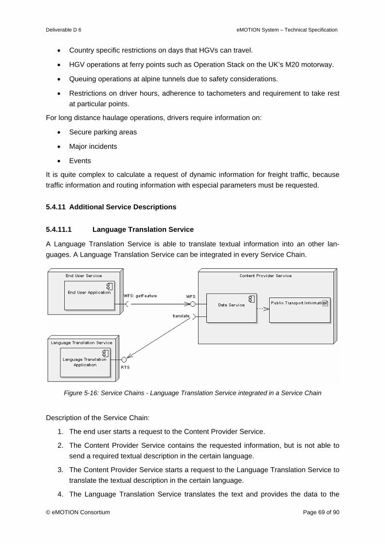
Deliverable D 6 eMOTION System – Technical Specification
© eMOTION Consortium Page 69 of 90
• Country specific restrictions on days that HGVs can travel.
• HGV operations at ferry points such as Operation Stack on the UK’s M20 motorway.
• Queuing operations at alpine tunnels due to safety considerations.
• Restrictions on driver hours, adherence to tachometers and requirement to take rest at particular points.
For long distance haulage operations, drivers require information on:
• Secure parking areas
• Major incidents
• Events
It is quite complex to calculate a request of dynamic information for freight traffic, because traffic information and routing information with especial parameters must be requested.
5.4.11 Additional Service Descriptions
5.4.11.1 Language Translation Service
A Language Translation Service is able to translate textual information into an other lan-guages. A Language Translation Service can be integrated in every Service Chain.
Figure 5-16: Service Chains - Language Translation Service integrated in a Service Chain
Description of the Service Chain:
1. The end user starts a request to the Content Provider Service.
2. The Content Provider Service contains the requested information, but is not able to send a required textual description in the certain language.
3. The Content Provider Service starts a request to the Language Translation Service to translate the textual description in the certain language.
4. The Language Translation Service translates the text and provides the data to the
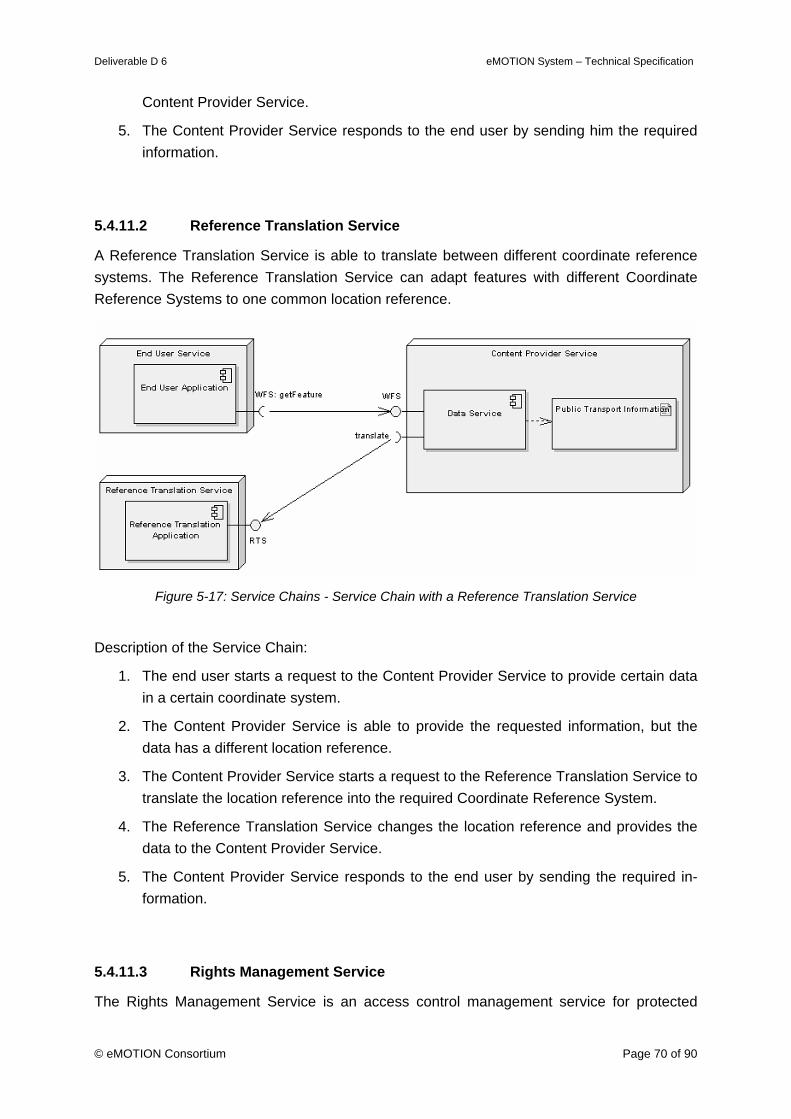
Deliverable D 6 eMOTION System – Technical Specification
© eMOTION Consortium Page 70 of 90
Content Provider Service.
5. The Content Provider Service responds to the end user by sending him the required information.
5.4.11.2 Reference Translation Service
A Reference Translation Service is able to translate between different coordinate reference systems. The Reference Translation Service can adapt features with different Coordinate Reference Systems to one common location reference.
Figure 5-17: Service Chains - Service Chain with a Reference Translation Service
Description of the Service Chain:
1. The end user starts a request to the Content Provider Service to provide certain data in a certain coordinate system.
2. The Content Provider Service is able to provide the requested information, but the data has a different location reference.
3. The Content Provider Service starts a request to the Reference Translation Service to translate the location reference into the required Coordinate Reference System.
4. The Reference Translation Service changes the location reference and provides the data to the Content Provider Service.
5. The Content Provider Service responds to the end user by sending the required in-formation.
5.4.11.3 Rights Management Service
The Rights Management Service is an access control management service for protected
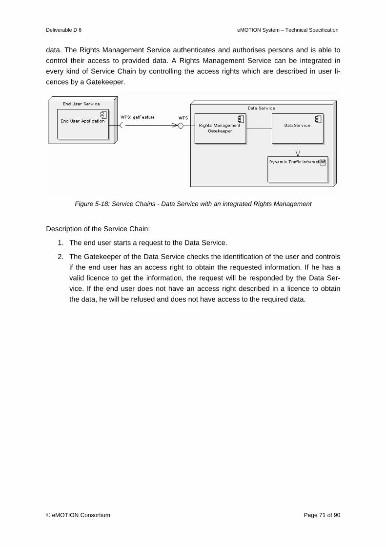
Deliverable D 6 eMOTION System – Technical Specification
© eMOTION Consortium Page 71 of 90
data. The Rights Management Service authenticates and authorises persons and is able to control their access to provided data. A Rights Management Service can be integrated in every kind of Service Chain by controlling the access rights which are described in user li-cences by a Gatekeeper.
Figure 5-18: Service Chains - Data Service with an integrated Rights Management
Description of the Service Chain:
1. The end user starts a request to the Data Service.
2. The Gatekeeper of the Data Service checks the identification of the user and controls if the end user has an access right to obtain the requested information. If he has a valid licence to get the information, the request will be responded by the Data Ser-vice. If the end user does not have an access right described in a licence to obtain the data, he will be refused and does not have access to the required data.
Deliverable D 6 eMOTION System – Technical Specification
© eMOTION Consortium Page 72 of 90
6. Engineering Viewpoint
This chapter is concerned with the infrastructure required to support the distribution of ser-vices and information sources of the eMOTION system. It focuses on the question how the interactions between the emotion service are accomplished using the defined interfaces.
The eMOTION system architecture is based on Web Services, XML (particularly GML) and Internet-technology. The end-user makes use of information services which are accessible through the mobile WWW. The application server of the information services accesses the relevant data from different data servers also via Internet.
6.1 Communication Model
The section defines the principle workings of the eMOTION distributed environment.
The communication model of the eMOTION architecture is based on the requirements of a typical distributed SOA. General architecture considerations can be found in chapter 3. Here we focus on protocols and standards suitable to establish an efficient and reliable communi-cation model for the exchange of information between nodes.
6.1.1 Main concepts
A short overview of the stack of network protocols used to define, localize, build and estab-lish interactions between web services is given. The stack of protocols is subdivided in the following areas:
Service Transport: responsible for the transportation of messages from/to applica-tions on the network. In eMOTION the reference service transport protocol is HTTP.
XML messaging: refers to message codification accordingly to the XML format so that every end of the network can understand and interpret messages. In eMOTION the reference XML messaging standard is SOAP.
Service description: the public interface of a web service is described by means of the Web Services Description Language (WSDL), a XML-based language used for the creation of documents with the specifications of interfaces and operations of a web service.
Service directory and discovery: refers to central resources for the localization of a web service based on specific features. In eMOTION a central registry service is de-fined (see 6.2.1).
All these standards and protocols fulfil some major requirements in eMOTION:
They are open
They are simple to understand (mostly text-based)
They allow interoperability between different platforms
SOAP has been introduced in Deliverable no. D 5 (Analysis of Technical Standards).

Deliverable D 6 eMOTION System – Technical Specification
© eMOTION Consortium Page 73 of 90
WSDL (Web Services Description Language) is an XML-based language used to describe the public interface of a Web Service. There are essentially three types of information de-scribing a web service in WSDL:
Operations available through the web service
Communication protocols used to access the service, format of the input and output messages, bindings
Service endpoints (‘where’ the service is available)
In WSDL we have:
Abstract operations and messages specifications that allow the definition of ‘univer-sal’ interfaces
Bindings to concrete network protocols and data format specifications allowing the use of such operations and messages within different platforms.
WSDL is usually combined with SOAP. A client node for example can determine what opera-tions are available from a web service through its related WSDL document and then use SOAP to access to one of the available operations.
WSDL version 2.0 is recognized as the official standard (W3C recommendation).
6.1.2 Communication model principles
The basic interaction principles for the protocols mentioned above can be summarized as follows:
«device» eMotion Client
Data Services
Publish operation
eMOTION central node
eMOTION Registry
Find operation
Bind Operations
SOAP Response
WSDL, Metadata WSDL, Metadata
SOAP Request
Figure 6-1: Communication Model - Publish-Find-Bind pattern and communication protocols
Following the publish-find-bind pattern of SOA, WSDL service description and associated
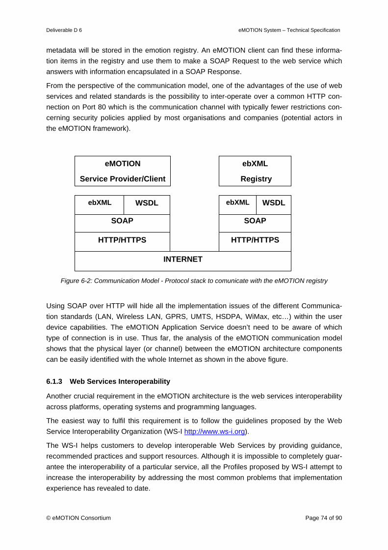
Deliverable D 6 eMOTION System – Technical Specification
© eMOTION Consortium Page 74 of 90
metadata will be stored in the emotion registry. An eMOTION client can find these informa-tion items in the registry and use them to make a SOAP Request to the web service which answers with information encapsulated in a SOAP Response.
From the perspective of the communication model, one of the advantages of the use of web services and related standards is the possibility to inter-operate over a common HTTP con-nection on Port 80 which is the communication channel with typically fewer restrictions con-cerning security policies applied by most organisations and companies (potential actors in the eMOTION framework).
Figure 6-2: Communication Model - Protocol stack to comunicate with the eMOTION registry
Using SOAP over HTTP will hide all the implementation issues of the different Communica-tion standards (LAN, Wireless LAN, GPRS, UMTS, HSDPA, WiMax, etc…) within the user device capabilities. The eMOTION Application Service doesn’t need to be aware of which type of connection is in use. Thus far, the analysis of the eMOTION communication model shows that the physical layer (or channel) between the eMOTION architecture components can be easily identified with the whole Internet as shown in the above figure.
6.1.3 Web Services Interoperability
Another crucial requirement in the eMOTION architecture is the web services interoperability across platforms, operating systems and programming languages.
The easiest way to fulfil this requirement is to follow the guidelines proposed by the Web Service Interoperability Organization (WS-I http://www.ws-i.org).
The WS-I helps customers to develop interoperable Web Services by providing guidance, recommended practices and support resources. Although it is impossible to completely guar-antee the interoperability of a particular service, all the Profiles proposed by WS-I attempt to increase the interoperability by addressing the most common problems that implementation experience has revealed to date.
SOAP
HTTP/HTTPS
INTERNET
ebXML WSDL
SOAP
HTTP/HTTPS
ebXML WSDL
ebXML
Registry
eMOTION
Service Provider/Client

Deliverable D 6 eMOTION System – Technical Specification
© eMOTION Consortium Page 75 of 90
The Basic Profile (version 1.1 at the time of the writing) provides interoperability guidance for a core set of non-proprietary web services specifications (such as SOAP, WSDL) along with interoperability-promoting clarifications and amendments to those specifications.
The profile is publicly available at http://www.ws-i.org/Profiles/BasicProfile-1.1.html.
The eMOTION architecture is intended to use some of these specifications and in particular, from the transportation point of view, some important constraints are underlined in the Basic Profile:
• Only HTTP (version 1.0 or 1.1) Bind is permitted in the SOAP Protocol binding;
• An HTTP request must use the HTTP POST method.
6.1.4 Security
Some of the services in the eMOTION network, like DRM or Payment and Billing, really need secured connections in order to be able to exchange confidential information (like Credit Card data).
The WS-I also specifies a profile, the Basic Security Profile (version 1.0 at the moment of the writing), dealing with transport security, SOAP messaging security and other security consid-erations.
The profile is publicly available at: http://www.ws-i.org/Profiles/BasicSecurityProfile-1.0.html.
Basic Profile and Basic Security Profile adopt the most widely used countermeasure against potential threats: HTTP secured (HTTP/S) with either TLS 1.0 or SSL 3.0 (SSL 2.0 is prohib-ited by the Profile for some well known security issues) as transportation layer mechanism.
Both TLS 1.0 and SSL 3.0 have been introduced in Deliverable no. D5 – Appendix 1 (Analy-sis of Technical Standards).
HTTP/S is widely regarded as a mature standard for encrypted transport connection to pro-vide a basic level of confidentiality and forms the simplest means of achieving some basic security features that are probably required by some of the real-world eMOTION services.
Following this guidelines, in the eMOTION network a basic secured connection is made by the use of HTTP/S with TLS 1.0 or SSL 3.0 as the underlying protocol.
To increase the level of security eMOTION services may also follow this other recommenda-tion of the Basic Security Profile:
• TLS-capable implementations may implement TLS_RSA_WITH_AES_-128_CBC_SHA, or FIPS equivalent, as encoding algorithm (called also ciphersuite);
• SSL-capable implementations may implement SSL_RSA_WITH_AES_-128_CBC_SHA, or FIPS equivalent, as encoding algorithm;
• Mutual authentication of HTTPS may be adopted when the authentication of the Web Service instance by the consumer is insufficient.
The above considerations permit a basic layer of security for the eMOTION network.
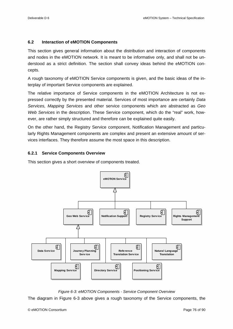
Deliverable D 6 eMOTION System – Technical Specification
© eMOTION Consortium Page 76 of 90
6.2 Interaction of eMOTION Components
This section gives general information about the distribution and interaction of components and nodes in the eMOTION network. It is meant to be informative only, and shall not be un-derstood as a strict definition. The section shall convey ideas behind the eMOTION con-cepts.
A rough taxonomy of eMOTION Service components is given, and the basic ideas of the in-terplay of important Service components are explained.
The relative importance of Service components in the eMOTION Architecture is not ex-pressed correctly by the presented material. Services of most importance are certainly Data Services, Mapping Services and other service components which are abstracted as Geo Web Services in the description. These Service component, which do the “real” work, how-ever, are rather simply structured and therefore can be explained quite easily.
On the other hand, the Registry Service component, Notification Management and particu-larly Rights Management components are complex and present an extensive amount of ser-vices interfaces. They therefore assume the most space in this description.
6.2.1 Service Components Overview
This section gives a short overview of components treated.
eMOTION Serv ice
Geo Web Serv ice Rights Management Support
Registry Serv ice
Data Serv ice
Mapping Serv ice
Journey Planning Serv ice
Positioning Serv iceDirectory Serv ice
Notification Support
Refe rence Translation Serv ice
Natura l Language Translation
Figure 6-3: eMOTION Components - Service Component Overview
The diagram in Figure 6-3 above gives a rough taxonomy of the Service components, the
Deliverable D 6 eMOTION System – Technical Specification
© eMOTION Consortium Page 77 of 90
interplay of which will be explained in greater detail in the following sections. Each of the components actually stands for a class of interrelated concepts and software components.
eMOTION Service stands for any Service component, created on the basis of the eMOTION Technical Specification.
There are four groups of Service components, of which Geo Web Services are the by most important, because they abstract the traffic and mobility information services proper. Nearly all Geo Web Service components deliver geo-data (hence the name). The Journey Planning Service has the most complex component model and is treated in detail.
Notification Support stands for Service components, which support the subscription process and call-back protocol employed to PUSH-type service delivery.
Registry Service stands for a singleton component in the central part of the eMOTION sys-tem. It stores and make available metadata, which is necessary to find and use eMOTION resources, including Services and Applications.
Rights Management Support comprises a significant set of Service components, which to-gether implement security. Though auxiliary, the model explanation is lengthy.
6.2.2 Information Provision and Use
This section depicts the main information flow in eMOTION.
Data Services and Mapping Services are by far the most often used resources in the eMO-TION system because they expose eMOTION’s standard interfaces for providing data and maps (WFS and WMS).
Note that for sake of simplicity the following scenarios and Figure 6-4 below omit all consid-erations concerning Rights Management. See 6.2.6 on how this can be added.
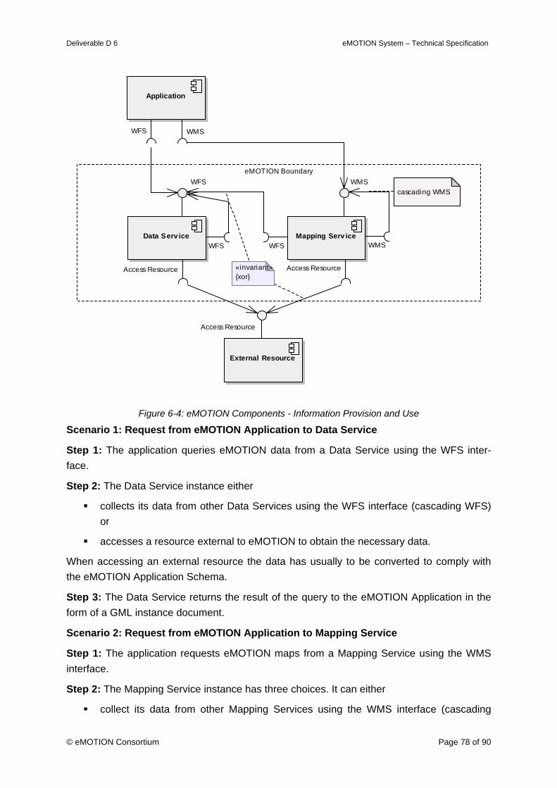
Deliverable D 6 eMOTION System – Technical Specification
© eMOTION Consortium Page 78 of 90
eMOTION Boundary
Data Serv ice
WFS
Access Resource
WFS
External Resource
Access Resource
Mapping Serv ice
WMS
Access Resource
WFS WMS
«invariant»{xor}
cascading WMS
Application
WFS WMS
Figure 6-4: eMOTION Components - Information Provision and Use
Scenario 1: Request from eMOTION Application to Data Service
Step 1: The application queries eMOTION data from a Data Service using the WFS inter-face.
Step 2: The Data Service instance either
collects its data from other Data Services using the WFS interface (cascading WFS) or
accesses a resource external to eMOTION to obtain the necessary data.
When accessing an external resource the data has usually to be converted to comply with the eMOTION Application Schema.
Step 3: The Data Service returns the result of the query to the eMOTION Application in the form of a GML instance document.
Scenario 2: Request from eMOTION Application to Mapping Service
Step 1: The application requests eMOTION maps from a Mapping Service using the WMS interface.
Step 2: The Mapping Service instance has three choices. It can either
collect its data from other Mapping Services using the WMS interface (cascading
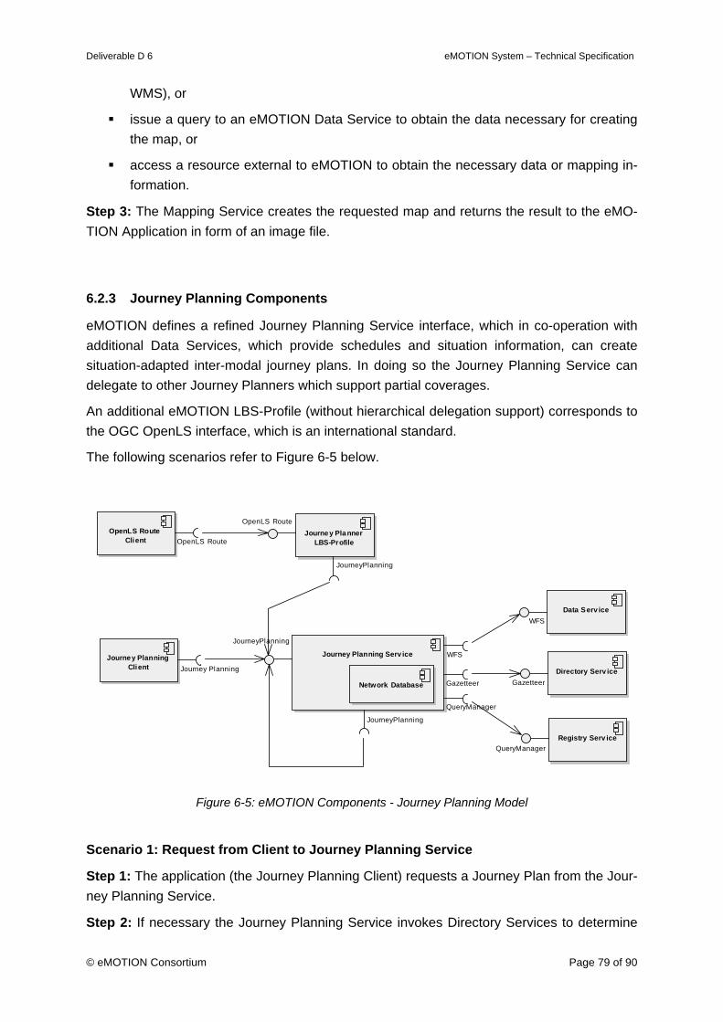
Deliverable D 6 eMOTION System – Technical Specification
© eMOTION Consortium Page 79 of 90
WMS), or
issue a query to an eMOTION Data Service to obtain the data necessary for creating the map, or
access a resource external to eMOTION to obtain the necessary data or mapping in-formation.
Step 3: The Mapping Service creates the requested map and returns the result to the eMO-TION Application in form of an image file.
6.2.3 Journey Planning Components
eMOTION defines a refined Journey Planning Service interface, which in co-operation with additional Data Services, which provide schedules and situation information, can create situation-adapted inter-modal journey plans. In doing so the Journey Planning Service can delegate to other Journey Planners which support partial coverages.
An additional eMOTION LBS-Profile (without hierarchical delegation support) corresponds to the OGC OpenLS interface, which is an international standard.
The following scenarios refer to Figure 6-5 below.
Journey Planning Serv ice
QueryManager
JourneyPlanning
JourneyPlanning
WFS
Gazetteer
Registry Serv iceQueryManager
Data Serv iceWFS
Directory Serv iceGazetteerNetwork Database
Journey Planner LBS-Profile
JourneyPlanning
OpenLS RouteOpenLS Route
Client OpenLS Route
Journey Planning Client Journey Planning
Figure 6-5: eMOTION Components - Journey Planning Model
Scenario 1: Request from Client to Journey Planning Service
Step 1: The application (the Journey Planning Client) requests a Journey Plan from the Jour-ney Planning Service.
Step 2: If necessary the Journey Planning Service invokes Directory Services to determine
Deliverable D 6 eMOTION System – Technical Specification
© eMOTION Consortium Page 80 of 90
the network positions of start point, end point and additionally waypoints.
Step 3: It finds out, whether it can answer the request on the basis of its own data or whether other Journey Planners have to be involved. If it can resolve the request on the basis of its own data, go to Step 9.
Step 4: The Journey Planner service invokes the Registry (the Journey Planning Register) to learn about eMOTION Journey Planners, which cover the journey request.
Step 5: In a preparation phase it requests the required exchange points of the concerned Journey Planners.
Step 6: It invokes the sub-ordinate Journey Planners determine all possible Journey Plans between start point, waypoints, end points and the determined exchange points.
Step 7: The responses are composed to continuous Journey Plans, whenever possible.
Step 8: The determined Journey Plans are possibly valued according to situation messages received from Data Services (congestions, delays, etc). This may result in re-evaluations with new waypoints in Step 4. Otherwise continue in Step 10.
Step 9: The Journey Planner can determine the Journey Plan on the basis of its Network Database and additional information about schedules and situation messages it receives from Data Services.
Step 10: The determined Journey Plans are returned to the requesting client.
Scenario 2: Request from Client to Journey Planner LBS-Profile
In this case the OpenLS request is either
delegated and resolved by means of an existing Services outside eMOTION, or
is in converted into a eMOTION Journey Planner request and sent to such a service.
6.2.4 Registry and Registry Use
The Registry Service is a queryable database of metadata required to discover and use eMOTION Services, Datasets and Applications (which together are called eMOTION Re-sources) and documents, which are required to get access to the resources and to use them.
The Registry is designed for use through a Portal and for automated use by services and arbitrary applications.
The first scenario refers to use of the Registry by eMOTION Services and by eMOTION Ap-plications. See Figure 6-6 below. The Figure also depicts the basic navigation functionality realised by the Registry.
Scenario 1: Use of the Registry from eMOTION Applications or Services
Step 1: An eMOTION Service or Application requests a query or an update of Registry con-tents. It uses the appropriate interface Query Manager or Lifecycle Manager.
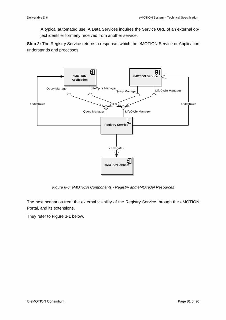
Deliverable D 6 eMOTION System – Technical Specification
© eMOTION Consortium Page 81 of 90
A typical automated use: A Data Services inquires the Service URL of an external ob-ject identifier formerly received from another service.
Step 2: The Registry Service returns a response, which the eMOTION Service or Application understands and processes.
eMOTION Serv ice
Query Manager LifeCycle Manager
Registry Serv ice
Query Manager LifeCycle Manager
eMOTION Application
Query Manager LifeCycle Manager
eMOTION Dataset
«navigate»
«navigate» «navigate»
Figure 6-6: eMOTION Components - Registry and eMOTION Resources
The next scenarios treat the external visibility of the Registry Service through the eMOTION Portal, and its extensions.
They refer to Figure 3-1 below.
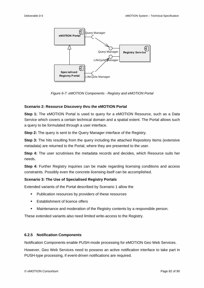
Deliverable D 6 eMOTION System – Technical Specification
© eMOTION Consortium Page 82 of 90
Registry Serv ice
LifeCycle Manager
Query Manager
eMOTION PortalQuery Manager
Spec ialised Regis try Portal LifeCycle Manager
Figure 6-7: eMOTION Components - Registry and eMOTION Portal
Scenario 2: Resource Discovery thru the eMOTION Portal
Step 1: The eMOTION Portal is used to query for a eMOTION Resource, such as a Data Service which covers a certain technical domain and a spatial extent. The Portal allows such a query to be formulated through a user interface.
Step 2: The query is sent to the Query Manager interface of the Registry.
Step 3: The hits resulting from the query including the attached Repository Items (extensive metadata) are returned to the Portal, where they are presented to the user.
Step 4: The user scrutinises the metadata records and decides, which Resource suits her needs.
Step 4: Further Registry inquiries can be made regarding licensing conditions and access constraints. Possibly even the concrete licensing itself can be accomplished.
Scenario 3: The Use of Specialised Registry Portals
Extended variants of the Portal described by Scenario 1 allow the
Publication resources by providers of these resources
Establishment of licence offers
Maintenance and moderation of the Registry contents by a responsible person.
These extended variants also need limited write-access to the Registry.
6.2.5 Notification Components
Notification Components enable PUSH-mode processing for eMOTION Geo Web Services.
However, Geo Web Services need to possess an active notification interface to take part in PUSH-type processing, if event-driven notifications are required.
Deliverable D 6 eMOTION System – Technical Specification
© eMOTION Consortium Page 83 of 90
For the following scenario see Figure 6-8 below.
Scenario 1: Geo Web Services Publishes notification ability
Step 1: A Geo Web Service, possessing the active Notify interface, which enables it to take part in event-driven PUSH-type processing, invokes a Notification Broker at the Register Publisher interface.
Step 2: The Geo Web Service is then (until recall) known to the Notification Broker.
Scenario 2: An eMOTION Service subscribes to a notification
Step 1: An eMOTION Service (or an Application) uses the Subscribe interface of the Sub-scription Manager to subscribe for notification regarding specific events from a particular Geo Web Service.
Step 2: The subscription is registered. It will also be recorded in the Registry Service.
Scenario 3: An event occurs and is passed to the subscriber
Step 1: A Geo Web Service experiences a significant event, which it passes to the Notifica-tion Broker via the Notify interface.
Step 2: If the Geo Web Service is known to the Notification Broker it asks the Subscription Manager, to return the subscriptions currently active for that Geo Web Service.
Step 3: The Subscription Manager returns the required subscription information. The infor-mation is checked against the event to determine which Service/ Application is to be notified.
Step 4: The Services or Applications which have been found out are notified. They will sub-sequently use the standard Geo Web Service interfaces to retrieve the information associ-ated with the notification.
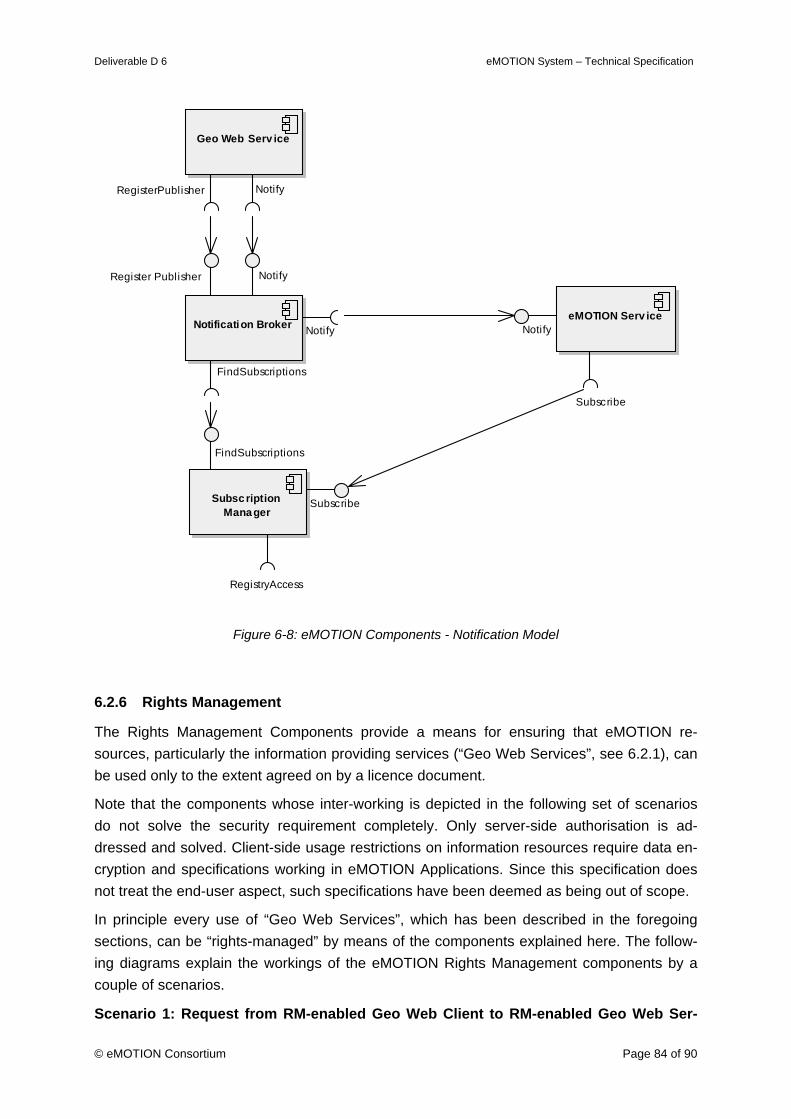
Deliverable D 6 eMOTION System – Technical Specification
© eMOTION Consortium Page 84 of 90
Geo Web Serv ice
NotifyRegisterPublisher
eMOTION Serv iceNotify
Subscribe
Subscription Manager
FindSubscriptions
RegistryAccess
Subscribe
Notification Broker
Notify
Notify
Register Publisher
FindSubscriptions
Figure 6-8: eMOTION Components - Notification Model
6.2.6 Rights Management
The Rights Management Components provide a means for ensuring that eMOTION re-sources, particularly the information providing services (“Geo Web Services”, see 6.2.1), can be used only to the extent agreed on by a licence document.
Note that the components whose inter-working is depicted in the following set of scenarios do not solve the security requirement completely. Only server-side authorisation is ad-dressed and solved. Client-side usage restrictions on information resources require data en-cryption and specifications working in eMOTION Applications. Since this specification does not treat the end-user aspect, such specifications have been deemed as being out of scope.
In principle every use of “Geo Web Services”, which has been described in the foregoing sections, can be “rights-managed” by means of the components explained here. The follow-ing diagrams explain the workings of the eMOTION Rights Management components by a couple of scenarios.
Scenario 1: Request from RM-enabled Geo Web Client to RM-enabled Geo Web Ser-

Deliverable D 6 eMOTION System – Technical Specification
© eMOTION Consortium Page 85 of 90
vice
Geo Web Serv iceGeo
GatekeeperGeoSAML+Geo
Authorize
Authorization Decision Serv iceGetAttributes
Authorize
GetLi cence
Identity Prov ider
SingleSignOn
GetAttributes
RegistryAccess
Geo Web Client RMSAML+Geo
SingleSignOn
OrderL icence
Figure 6-9:eMOTION Components - RM-enabled Geo Web Service Execution
Step 1: The agent using the RM-enabled Geo Web Client (GWC) identifies itself by entering appropriate credentials, e.g. username/password, which are passed to the Identity Provider (IP) service.
What the Identity Provider Does
The Identity Provider finds out whether an agent trying to access a service is known. It knows the means to establish his identity (e.g. password) and can provide any iden-tifying attributes (e.g. name, phone number)
Step 2: The IP verifies the agent's credentials (by lookup in an appropriate repository or ser-vice). Upon successful verification, it creates a SAML assertion containing an authentication statement and passes it as security token (by value or reference) back to the GWC.
Step 3: The GWC attaches the security token to any request message it sends to an RM-enabled OGC Web Service (RMGWS).
Step 4: The message is decoded by the Gatekeeper (GK) component of the RMGWS. The GK extracts the subject id of the agent from the security token, and passes it together with action and resource information to the Authorization Decision Service (ADS) using the XACML protocol.
What the Gatekeeper and Authorization Decision Service Do
The Gatekeeper executes an authorization decision, i.e. a decision to allow or deny the use of a resource.
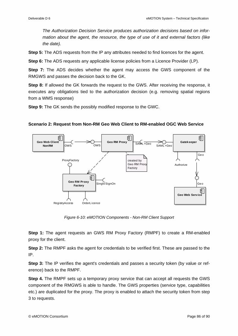
Deliverable D 6 eMOTION System – Technical Specification
© eMOTION Consortium Page 86 of 90
The Authorization Decision Service produces authorization decisions based on infor-mation about the agent, the resource, the type of use of it and external factors (like the date).
Step 5: The ADS requests from the IP any attributes needed to find licences for the agent.
Step 6: The ADS requests any applicable license policies from a Licence Provider (LP).
Step 7: The ADS decides whether the agent may access the GWS component of the RMGWS and passes the decision back to the GK.
Step 8: If allowed the GK forwards the request to the GWS. After receiving the response, it executes any obligations tied to the authorization decision (e.g. removing spatial regions from a WMS response)
Step 9: The GK sends the possibly modified response to the GWC.
Scenario 2: Request from Non-RM Geo Web Client to RM-enabled OGC Web Service
Geo Web Serv ice
Geo
Gatek eeper
Ge o
SAML +Geo
Authorize
Geo Web Cl ient NonRM OWS
Geo RM Proxy Factory Single SignOn
RegistryAccess
ProxyFactory
OrderL icence
Geo RM ProxyOWS SAML +Geo
created by Geo RM ProxyFactory
Figure 6-10: eMOTION Components - Non-RM Client Support
Step 1: The agent requests an GWS RM Proxy Factory (RMPF) to create a RM-enabled proxy for the client.
Step 2: The RMPF asks the agent for credentials to be verified first. These are passed to the IP.
Step 3: The IP verifies the agent's credentials and passes a security token (by value or ref-erence) back to the RMPF.
Step 4. The RMPF sets up a temporary proxy service that can accept all requests the GWS component of the RMGWS is able to handle. The GWS properties (service type, capabilities etc.) are duplicated for the proxy. The proxy is enabled to attach the security token from step 3 to requests.
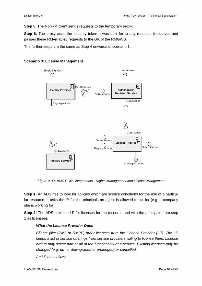
Deliverable D 6 eMOTION System – Technical Specification
© eMOTION Consortium Page 87 of 90
Step 5. The NonRM client sends requests to the temporary proxy.
Step 6. The proxy adds the security token it was built for to any requests it receives and passes these RM-enabled requests to the GK of the RMGWS.
The further steps are the same as Step 4 onwards of scenario 1.
Scenario 3: License Management
Authorization Decision Serv iceGetAttributes
Authorize
GetLi cence
Identity Prov ider
SingleSignOn
GetAttributes
RegistryAccess
Registry Serv ice
RegistryAccess
Licence Prov iderGetAttributes
GetLi cence
OrderL icenceRegistryAccess
ManageOffering
Figure 6-11: eMOTION Components - Rights Management and License Mangement
Step 1: An ADS has to look for policies which are licence conditions for the use of a particu-lar resource. It asks the IP for the principals an agent is allowed to act for (e.g. a company she is working for)
Step 2: The ADS asks the LP for licenses for the resource and with the principals from step 1 as licensees
What the License Provider Does
Clients (like GWC or RMPF) order licences from the Licence Provider (LP). The LP keeps a list of service offerings from service providers willing to license them. License orders may select part or all of the functionality of a service. Existing licenses may be changed (e.g. up- or downgraded or prolonged) or cancelled.
An LP must allow:
Deliverable D 6 eMOTION System – Technical Specification
© eMOTION Consortium Page 88 of 90
o Retrieval of license conditions
o License transactions from trusted parties
o Service offering transactions from trusted parties
Step 3: The LP returns the fitting policies.
6.3 Identifier Model
All feature and object instances pursuant to the eMOTION Data Model (instances of classes derived from EMotionFeature or EMotionObject) require unique and persistent identifiers.
Instances of the conceptual eMOTION Data Model (modelled in UML) are externally visible thru instances of the GML Application Schema, which is derived automatically form the UML model.
In this GML representation feature and object identifiers appear in form of the gml:id attribute on the feature element.
Example:
<PointOfInterest gml:id=”A8FF89C7.lkk-0000037”> … </PointOfInterest>
Note that for syntactical reasons those identifiers have to comply with a restricted character set. Exactly defined, identifiers represent the ID attribute type of the XML 1.0 definition. The alphabet is roughly the ASCII letters, digits, hyphen (-) and underscore (_). The dot (.) is ad-ditionally allowed, however, is reserved for a special purpose in eMOTION. They also have to start with an alphabetical character.
Content Providers and Providers of Service instances, which deliver eMOTION Data are re-sponsible for ensuring the persistence of identifiers.
To ensure eMOTION-wide uniqueness of identifiers each eMOTION Service possesses a unique namespace identifier, which can be inquired from the eMOTION Registry (from the OID namespace register). When generating externally visible identifiers, eMOTION Services shall prefix their identifiers, which are unique in the scope of the Service by these name-spaces prefixed from the Registry. Both parts shall be separated by a dot (.).
gml:id=”namespace-prefix.locally-unique-identifier”
The same type of identifier also has to be used in feature and object references. If a refer-ence expressed by means of an xlink:href attribute is not document local, in which case the #label syntax shall be used, it shall follow the syntax:
xlink:href=”urn:x-eMOTION:ref:namespace-prefix.locally-unique-identifier”
Clients can parse these identifiers to look up the namespace prefix in the Registry. They can in this way find the Service, which provides the referenced feature or object.
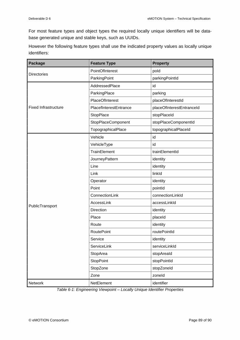
Deliverable D 6 eMOTION System – Technical Specification
© eMOTION Consortium Page 89 of 90
For most feature types and object types the required locally unique identifiers will be data-base generated unique and stable keys, such as UUIDs.
However the following feature types shall use the indicated property values as locally unique identifiers:
Package Feature Type Property
PointOfInterest poId Directories
ParkingPoint parkingPointId
AddressedPlace id
ParkingPlace parking
PlaceOfInterest placeOfInterestId
PlacefInterestEntrance placeOfInterestEntranceId
StopPlace stopPlaceId
StopPlaceComponent stopPlaceComponentId
Fixed Infrastructure
TopographicalPlace topographicalPlaceId
Vehicle id
VehicleType id
TrainElement trainElementId
JourneyPattern identity
Line identity
Link linkId
Operator identity
Point pointId
ConnectionLink connectionLinkId
AccessLink accessLinkId
Direction identity
Place placeId
Route identity
RoutePoint routePointId
Service identity
ServiceLink serviceLinkId
StopArea stopAreaId
StopPoint stopPointId
StopZone stopZoneId
PublicTransport
Zone zoneId
Network NetElement identifier Table 6-1: Engineering Viewpoint – Locally Unique Identifier Properties
Deliverable D 6 eMOTION System – Technical Specification
© eMOTION Consortium Page 90 of 90
7. Literature
[EPSG, 2007] ”EPSG Geodetic Parameter Registry”, Version: 6.14, OGP Surveying and Positioning Com-mittee, 2007, http://www.epsg-registry.org/
[GeoTIFF, 2000] ”GeoTIFF Format Specification GeoTIFF Revision 1.0”, GeoTIFF Working Group, Specifica-tion Version: 1.8.2, http://www.remotesensing.org/geotiff/spec/geotiffhome.html
[GIF, 1989] ”GRAPHICS INTERCHANGE FORMAT(sm), Version 89a, (c)1987,1988,1989,1990, Copy-right CompuServe Incorporated Columbus, Ohio, http://www.w3.org/Graphics/GIF/spec-gif89a.txt
[INSPIRE-CRS, 2003] ”Map Projections for Europe”, European Communities, 2003
[ISO 19136, 2007] ”Geographical information – Geography Markup Language (GML)”, International Organiza-tion for Standardization (ISO), 2007
[ISO 10746-1, 1998] "ISO/IEC 10746-1: Information technology -- Open Distributed Processing -- Reference model: Overview", International Organization for Standardization (ISO), 1998.
[ISO 10918-1, 1994] ” ISO/IEC 10918-1:1994 Information technology -- Digital compression and coding of con-tinuous-tone still images: Requirements and guidelines”, International Organization for Stan-dardization (ISO), 1994
[OGC-URN, 2007] ”Definition identifier URNs in OGC namespace”, Version 1.1.2, OGC 07-092r1, 2007
[PNG, 1997] ”PNG (Portable Network Graphics) Specification Version 1.0”, IETF, RFC 2083, http://tools.ietf.org/html/rfc2083
[UCUM, 2005] ”The Unified Code for Units of Measure”, The Regenstrief Institute For Health Care, Indian-apolis, 2005 (http://aurora.regenstrief.org/UCUM)