emerging challenges of fuel · pdf filediesel fuel has evolved from having high sulphur...
TRANSCRIPT

the international journal for filtration and separation
ISSN 1479-0602
www.filtrationsolutions.co.uk Volume 10 Number 2
FILTRATION is the official journal of The Filtration Society and the American Filtration & Separations Society

FILTRATION, 10(2), 2010
105
Filtration Solutions
INTRODUCTION Advances in fuel filtration technology depend heavily on the nature of the fuels. Diesel fuel has evolved from having high sulphur content, to low and presently to ultralow. In the United States (US) and Europe, the increasing desire of oil independence and green energy initiatives are driving the introduction of biodiesel from feed stocks such as vegetable oils and animal fats. More recently research is extending to algae and other bioprocesses for production of biofuels1.
For the foreseeable future, ultra-low sulphur diesel (ULSD) and ULSD/biodiesel blends will influence the transportation diesel fuel market. In the US, ULSD has been mandated since October 2006. B2, a 2% blend of biodiesel in ULSD, was mandated in Minnesota three years ago, and more aggressive use of biodiesel blends of up to 5-15% are under way or being planned by the state governments.
Concurrently, engine designs are evolving to meet more stringent emission regulations, and these engines require a much higher level of fuel cleanliness. Fuel filtration must be designed to achieve these increasing levels of cleanliness to protect the engine and its components from wear and damage. Thus, changes in both fuel and engine designs are bringing a new level of complexity to filtration including a requirement for finer particle filtration and the need to reduce or eliminate fine water droplets. Filtration is further complicated by the increase of organic contaminants present in diesel fuels. High efficiency diesel fuel filtration is typically achieved on a vehicle; however, with increasing cleanliness requirements and water content, there is an emerging opportunity for bulk fuel filtration.
In light of this perspective, the diesel fuel filtration market looks very promising. Today, with total diesel engine production in 2008 of 30 million engines, we estimate the diesel fuel filtration market to be about $8B. Trends show increasing use of alternative fuels and the need for integration of more features and functions into fuel filtration systems. Understanding the limitations of today’s fuel filtration as well as emerging industry needs creates an opportunity for addressing these challenges with innovative technology.
EMISSION REGULATIONS ARE DRIVING
CHANGES IN FUELS Changes in emission regulations continue to drive significant changes in the design of past, current and future diesel engines. Filtration development has centred on exhaust emissions including particulates, nitrogen oxides (NOx), hydrocarbons and carbon monoxide. For example, particulate matter (PM) and NOx emissions are being partially controlled through elevated fuel injector pressures, multiple injections and controlled combustion temperatures. Injector pressures have risen from 1000 bar in the 1980’s up to 2500 bar today and are projected to pass 3500 bar in the next few years. These increased pressures require reduced component clearances on the order of 2-5 μm, thereby placing a higher demand on fuel cleanliness. In addition to changes in engine and injector design, current and future emission regulations also require usage of catalytic control systems to mitigate NOx and PM emissions. In order to facilitate the usage of these control systems, the sulphur content of diesel fuel was reduced to prevent catalyst poisoning2. Using ULSD limits the amount of sulphur
Tougher environmental regulations, a move toward energy security and sustainability and emerging green initiatives are significantly impacting the fuel industry. Removal of sulphur from traditional diesel fuels to produce a cleaner burning fuel and the introduction of biofuels derived from non-fossil fuel sources are lead-ing to new challenges in particle, water and soft organic contaminants filtration. In addition, new engine designs developed to meet environmental concerns require higher levels of fuel cleanliness. Thus, provid-ing higher performance fuel filtration to achieve these new cleanliness standards is further exacerbated by the complex nature of the evolving diesel fuels. An emerging challenge for filter manufacturers is designing systems which retain filtration performance under actual operating conditions. Historically, filters were evaluated using standard laboratory tests that do not necessarily reflect real world driving conditions where cyclic flow and vibration are common phenomena. There is also a trend toward fuel system flexibility which helps manufacturers integrate multiple functions into a fuel filter module. A modular design is a cost effec-tive means for providing a variety of performance features which allows individualization of the fuel filtration system.
EMERGING CHALLENGES OF FUEL FILTRATION
Debra Wilfong, Andrew Dallas, Chuanfang Yang ([email protected]), Philip Johnson, Karthik Viswanathan, Mike Madsen, Brian Tucker and John Hacker
Donaldson Company, Minneapolis, MN 55431, USA.

FILTRATION, 10(2), 2010
106
Filtration Solutions
based compounds in the exhaust allowing these catalysts to operate efficiently over the vehicle life.
ULTRA-LOW SULPHUR DIESEL FUELS
ULSD is mandated by environmental regulatory bodies in the US, Japan and the European Union (EU) since it is considered a cleaner burning fuel. ULSD, or S15, is defined by the U.S. Environmental Protection Agency (EPA) as diesel fuel with a maximum sulphur content of 15 ppm (parts per million). Low sulphur diesel (LSD), LS500, is defined as diesel having a sulphur content of less than 500 ppm. These designations are used throughout North America; however, in other regions of the world, sulphur content can vary and may exceed these limits. In 2006, the change from LSD to ULSD was initiated across the U.S. Current EPA regulations require 80% of all on-road diesel fuel be ULSD by 2010. For off-road vehicles, diesel fuel was limited to LSD in 2007 and will start moving towards ULSD by 2010.
The difference between LSD and ULSD fuel lies not only in the sulphur content, but also in the physical and physicochemical properties. To make ULSD from crude oil, the refinery typically applies a hydrotreating process for desulphurization. As a result, not only sulphur is removed, but also some naturally-occurring lubricants. In addition, distillation temperature, fuel oxidation stability, conductivity, and aromatics content are lowered, while cetane number, cloud point and wax content are increased3. These changes are dependent on refinery feed stocks and specific
operating conditions for desulphurization such as temperature, pressure and catalysts3.
OIL DEPENDENCY INITIATIVES ARE DRIVING
DEVELOPMENT OF BIOFUELS Worldwide production of oil is currently around 90 million barrels per day. An approximate distribution of manufactured oil products coming out of a typical refinery is shown in Figure 14. It is noteworthy that a majority of oil production goes into liquid fuels and only a relatively small portion of all crude oil refining finds its way into non-fuel products. Approximately 80% of the 90 million barrels per day is converted into fuels for combustion engines. Of the 80%, almost 15% (500+ million gallons per day) of this fuel is currently used in diesel engines. Over the next ten years, this percentage is expected to grow5. Some projections show more than one in four internal combustion engines made will be a diesel engine by 2020. This is an increase from one diesel engine in five in 20035.
Long term energy security and sustainability call for reduced dependency on fossil fuels. Initiatives to reduce dependency on fossil fuels are driving development of biofuels derived from plant or animal based sources. From a transportation perspective, some studies have indicated that utilization of biodiesel can reduce the amount of hydrocarbon and carbon monoxide emissions since these fuels are typically more oxygenated than traditional diesel fuels and consequently cleaner burning. Similar studies have shown that PM emissions can be reduced with usage
Figure 1: Approximate distribution of manufactured oil products from a barrel of oil.
Finished MotorGasoline, 51%
Asphalt & Road Oil, 2%Other Refined Prod., 2%
Lubricants, 1%
Residual Fuel Oil, 3%
Liquid Refinery Gas, 3%
Distillate Fuel Oil, 15%
Jet Fuel, 13%
Still Gas, 5%
Marketable Coke, 5%
Finished MotorGasoline, 51%
Asphalt & Road Oil, 2%Other Refined Prod., 2%
Lubricants, 1%
Residual Fuel Oil, 3%
Liquid Refinery Gas, 3%
Distillate Fuel Oil, 15%
Jet Fuel, 13%
Still Gas, 5%
Marketable Coke, 5%

FILTRATION, 10(2), 2010
107
Filtration Solutions
of biodiesel6.
BIODIESEL
Biodiesel is a fuel produced from renewable resources such as soybean or rapeseed oils. The burgeoning biodiesel industry is associated with renewable energy development efforts. Despite the debate on non-sustainable food-to-energy, biodiesel is emerging as an alternative to ULSD or as a blend with ULSD. Feed stocks in addition to soybean or rapeseed are being investigated. In the US, soybean oils and animal fats are major sources for large scale biodiesel production. For soybean oil, a transesterification process is employed where the oil is converted to a methyl ester by reacting with methanol using NaOH or KOH as the catalyst.
Use of biodiesel or its blends with fossil fuel based diesels reduces overall dependency on crude oil. However, biodiesel is less stable and more hygroscopic than ULSD. It is also known to have a higher cloud point and more unsaturated hydrocarbon content which can lead to earlier wax precipitation and increased intensity of fuel oxidation causing premature fuel filter plugging. However, biodiesel blended with fossil fuel based diesel can improve its performance with diesel engines. These blends can improve lubrication properties, provide higher cetane number and reduce emissions relative to ULSD7.
In addition to efforts directed toward biodiesel, there is also ongoing activity in Brazil blending ethanol with diesel fuels. Vegetable oil has also been blended directly with diesel fuels.
CONTAMINANTS IN FUELS
There are many opportunities for contaminant ingress in fuels from production to point of use. Filtration of diesel fuel on mobile vehicles dates back to the earliest installations of diesel engines. An early paragraph written on diesel system care came out of a 1931 Caterpillar owner’s manual. It states that 90% of diesel problems are due to dirt or water in the fuel8. Although emission standards have led to removal of sulphur from today’s diesel fuels, dirt, water and soft organic contaminants still remain.
Common rail fuel injection systems utilized on modern low emission engines have critical filtration requirements due to their ever increasing operating pressures and correspondingly tighter clearances required for both injectors and pumps. On-vehicle filtration is the last line of defence for an engine to function efficiently over long service intervals. For the filtration industry this represents emerging challenges for developing next generation fuel filter technology for managing 1) particles, 2) water, and 3) soft organics.
Particles in Fuel Particulate contaminants include road dusts, engine rust or wear particles, and any other hard particles that can cause engine damage. These particles are typically rigid in nature and can cause severe wear to a fuel injection system. The extent of damage realized depends on particle size, shape, rigidity, concentration and sometimes on chemical composition.
Particle contamination makes its way into vehicle fuel systems through multiple paths. One source is the diesel fuel itself. Diesel fuel cleanliness varies from gas pump to gas pump. Typical fuel cleanliness levels coming out of the pump are ISO rated at 22/21/18. (ISO cleanliness code of 22/21/18 translates to a particle count of 20,000 to 40,000 per ml for particles of 4 μm and greater; 10,000 to 20,000 per ml for particles of 6 μm and greater; and 1300 to 2500 per ml for particles of 14 μm and greater).
A second source of ingress is through the tank vent. As the fuel tank is drawn down ambient air is drawn into the tank. Furthermore, wear debris from fuel system components provide yet another source of particles.
One measure of relative injector wear is the ability to flow more fuel through the injector orifice. Fuel injector nozzle orifice wear is shown to increase as a function of particle contaminant concentration in Figure 29. Erosion of a nozzle orifice can adversely affect the atomization process thus negatively impacting emissions. Consequently, clean fuel minimizes fuel system wear and engine exhaust emissions.
Diesel fuel pump manufacturers are already requiring fuel with ISO cleanliness counts of 13/9/6 or better at the injector; with typical fuel cleanliness levels coming out of the gas pump at 22/21/18, this represents a thousand fold reduction in contaminant required by the time the fuel reaches the fuel injector system10.
1E+3 1E+4 1E+5 1E+6 1E+7 1E+80
5
10
15
20
25
30
290 mi
2900 mi
29,000 mi
290 k mi2.9 m mi
1E+3 1E+4 1E+5 1E+6 1E+7 1E+80
5
10
15
20
25
30
290 mi
2900 mi
29,000 mi
290 k mi2.9 m mi
Exposure (particle-hr/ml)
Flow
incr
ease
(%)
Figure 2: Fuel injector nozzle wear represented by increase in fuel flow as a function of particle concentration.
Assumption 2 ppm fuel.

FILTRATION, 10(2), 2010
108
Filtration Solutions
In terms of particle filtration efficiency, beta ratio is still a quantitative way to define filter medium effectiveness to keep fuel relatively free of damaging wear particles. Beta ratios, defined as the ratio of the number of particles upstream to the number of particles downstream at a specific particle size, are often inadequate measures of fuel filter performance. Beta ratios are derived from standardized multi-pass fuel filter tests while on-vehicle fuel filtration generally occurs in a single pass. ISO cleanliness level at the fuel injector may well be an improved method for measuring a filter’s performance10.
In addition, standard laboratory tests generally use silica ISO dusts (see Figure 3A) to quantify a filter’s dust capacity and dust filtration efficiency. However, it is well known that ISO dusts do not necessarily represent real-world contaminants as shown in Figure 3B, and therefore do not provide an adequate representation of actual filter performance.
Generally, particle filtration media include, but are not limited to, cellulose, glass, blends of cellulose and glass, melt blown/cellulose composites and spunbond polyester. Particles capable of causing wear in today’s common rail fuel systems are significantly smaller than the primary wear contributors twenty years ago. Today, particles significantly smaller than four microns are now potential wear contributors. These smaller particle sizes challenge the limits of our measurement capabilities.
These fine particulate contaminants will require both new filtration technology and a corresponding systems approach to successfully remove them from diesel fuels; with current filtration technology it may be no longer practical to rely solely on on-vehicle filtration systems to control fine particles. Filtration of fuels at each transfer point, from production to the gas station pump, may be necessary as performance requirements for particle filtration become more stringent.
Water in Fuel Water found in diesel fuels can cause engine part corrosion and erosion, fuel lubricity deterioration, fuel pump cavitation, fuel injector deposit build-up and fuel filter plugging. It can also promote fuel instability and at the fuel/water interface provide an environment where bacteria can grow. Water can be found within fuel as free water, dissolved water and emulsified water.
Dissolved water is dispersed in fuel molecule-by-molecule. Once the amount of water exceeds the maximum level for it to remain dissolved, water will fall out of the fuel, forming a water-in-fuel emulsion with small water droplets suspended in the fuel. When more water is unavoidably introduced in the fuel during fuel storage, shipping, pumping and through condensation, free water can be found at the bottom of storage or fuel tanks due to the difference in density between fuel and water. Free and emulsified water must be effectively removed from fuel and a significant amount of dissolved water can also be a potential threat to the engine. World Fuel Charters recommends a maximum water content to be less than 200 ppm10.
Water contamination is introduced to the fuel system through the same basic paths as particle contamination. On road vehicles fuelling at truck stops and service stations draw fuel from relatively controlled sources, and pumps have point of use filters to help control free and emulsified water contamination. However, water can also be transferred into the vehicle’s fuel tank as the level of dissolved water in the fuel equilibrates with the relative humidity of the outside surroundings. Therefore, at a minimum, some water will always be brought into the vehicle’s fuel system when fuelling. For remote off road sites such as mines, controlling fuel storage and dispensing conditions are more challenging and the chance of introducing substantially larger quantities of water are
Figure 3: Scanning Electron Micrographs (SEMs) of: A) ISO fine dust; B) a used diesel fuel filter.
AA BB

FILTRATION, 10(2), 2010
109
Filtration Solutions
much greater.
Water also enters the fuel systems through fuel tank vents, but unlike particle contamination, water is not necessarily driven by the level of fuel in the tank but rather by fluctuations in environmental conditions, i.e. changes in temperature and relative humidity.
‘Typical’ water saturation vs. temperature values for diesel fuel are not readily available since they fluctuate widely from batch to batch and from refinery to refinery. Laboratory testing at Donaldson Company indicates that it is not unusual for a ULSD fuel to have a 50 ppm water saturation limit at around 50°F and close to a 200 ppm saturation limit at 100°F. Using these two values, a 50 degree temperature swing from 50°F to 100°F at 100% RH increases the dissolved water concentration of the fuel from 50 ppm to 200 ppm. This amounts to 1.7 ounces of water for every 100 gallons of fuel. When fuel in the tank and air space above it cools to 50°F the dissolved water holding capacity of the fuel is reduced to its starting value and the calculated amount of water is dropped out of solution and into the fuel tank as free or emulsified water.
In ULSD, loss of naturally occurring lubricants must be compensated with lubricity additives to protect the moving components of the engine that rely on fuel as their lubricant. These lubricity additives increase fuel surfactancy, which in turn has the unintended effect of increasing stability of water droplets in the fuel. Filtration of this emulsified water is more challenging than removal of the larger droplets found in LSD.
For water in fuel, interfacial tension (IFT) is a measure of the affinity between water and fuel. A lower value of IFT represents a higher affinity where water is more difficult to separate from fuel. Water droplet size in fuels with different interfacial tensions (IFT) as a function of water concentration is shown in Figure 411. As IFT is lowered, the mean water droplet size becomes smaller and smaller, and consequently more difficult to remove. At higher IFT, the droplet size increases with increasing water concentration; however, this trend does not persist below an IFT of 10 mN/m. At IFTs below 10 mN/m, the emulsion is stable enough to prevent further coalescence of water droplets; this is true even at elevated water concentrations.
These stable water-in-fuel emulsions render traditional fuel/water separation media, such as water-repellent cellulose and melt blown/cellulose composites, ineffective. These media are typically designed for relatively high IFT fuel and coarse water filtration where emulsion stability is not an issue.
Biodiesel is inherently more hygroscopic than ULSD due to its polar fatty acid and methyl ester composition and its residual glycerin by-products created during the
transesterification process. In addition, emulsified water in biodiesel is believed to have a finer droplet distribution due to the surfactant nature inherent in the fatty acids and the role of glycerin in stabilizing the emulsion. Consequently, when biodiesel is blended with ULSD, emulsified water removal becomes even more challenging.
Regardless of these technical challenges, the fuel filtration industry is facing a test standard issue. For example, the current US emulsified water filtration test standard, SAE J1488, is no longer representative of today’s fuels. ULSD and its biodiesel blends can exhibit a range of interfacial tension from about 3 to 30 mN/m. The current standard specifies fuel with an interfacial tension of 25-30 mN/m. Consequently, a fuel/water separator that passes this standard test with over 95% efficiency may not work for real world fuels having low interfacial tension. ISO/TC 16332 was developed to tackle this problem but is being challenged by participating members. The issues are how to select a standard fuel for water/fuel separation tests, and how to generate a water-in-fuel emulsion more representative of real world fuels.
Organic Contaminants in Fuel Organic contaminants can be soft, sticky or slimy in nature. They can occur naturally or as a result of fuel degradation. These contaminants are not well defined, however, they can be naturally occurring compounds, end products of fuel oxidation through thermal stressing, by-products of fuel additives interacting with fuel constituents, ‘apple jelly’ types of materials that have something to do with water contamination, or a mix of all of these phenomena.
Filters plugged with diesel fuel organic contaminants are shown in Figure 5. A typical ULSD fuel filter after use is shown in Figure 5A and similarly after use with biodiesel in Figure 5B. It can readily be seen that the fuel type has a dramatic impact on the morphology and structure of the organic contaminants. Note the differences between the organic contaminant formed
Figure 4: Mean droplet size as a function water concentration and IFT.
0
5
10
15
20
25
30
35
40
45
0 1000 2000 3000 4000 5000 6000Water concentration (ppm)
Mea
n w
ater
dro
plet
siz
e (u
m) IFT=38.0
IFT=31.8
IFT=20.9
IFT=8.4
0
5
10
15
20
25
30
35
40
45
0 1000 2000 3000 4000 5000 6000Water concentration (ppm)
Mea
n w
ater
dro
plet
siz
e (u
m) IFT=38.0
IFT=31.8
IFT=20.9
IFT=8.4
Water concentration (ppm)
Mea
n w
ater
dro
plet
siz
e (μ
m)

FILTRATION, 10(2), 2010
110
Filtration Solutions
from ULSD as compared to that from biodiesel in Figures 5C and 5D respectively.
The complexity and variety of fuel contaminants are revealed in Figure 6. Diesel fuels contain long chain paraffinic molecules. These higher carbon content molecules generally have higher cetane level for improved combustion during compression ignition. Reduction of aromatics in ULSD lowers wax solubility and promotes wax precipitation when temperature is lowered. This can lead to premature plugging of fuel filters.
ULSD organic contaminants can also damage elastomeric fuel filter seals and consequently shorten filter life. In this case, the organic contaminants are the result of free radical reactions. These reactions are accelerated for ULSD due to the removal of naturally occurring antioxidants from the refinery’s hydrotreating process. As a result a large number of hydrocarbon peroxides are generated. These peroxides promote oxidation and polymerization of unsaturated fuel molecules, and have a damaging effect on elastomeric seals used in vehicle fuel systems. When fuel temperature is raised and in contact with metal surfaces, oxidation becomes increasingly problematic forming organic acids that may cause engine corrosion. With further oxidation, organic sediments can also be formed. As a result, fuel filters may be clogged prematurely and fuel injectors may be fouled or plugged. To prevent this, fuel stabilizers are typically used. However, under fuel
thermal stress conditions, other fuel contaminants can coexist as oxidation sources and reduce the effectiveness of antioxidant additives.
For biodiesel, fuel oxidation is related to the rate of reaction of fuel molecules with oxygen through a free-radical initiated mechanism. This is important because the end products of oxidation may contain soft sticky particles that can adhere to fuel filters and engine components. The induction period of oxidation is used as a standard to quantify fuel oxidation stability. The longer the induction period, the more resistant the fuel is to oxidation when exposed to oxygen or air. When biodiesel is blended with ULSD the induction period decreases as the blend ratio increases as is shown in Figure 712.
It was observed that a fuel’s oxidation stability does not necessarily correlate to formation of the solid contaminants that causes filter plugging; however, improved oxidation stability prevents deposits and increases both reliability and working life in engines and filters13.
FUEL FILTRATION SYSTEMS
Fuel filters are as widely varied as the vehicles on which they are used. A range of products aimed at the more traditional fuel markets is shown in Figure 8. Spin on filters are most commonly utilized in the fuel market world wide; however, new global demands are changing the configurations desired for vehicles in
Figure 5: A) plugged ULSD fuel filter, B) plugged biodiesel fuel filter, C) SEM of ULSD formed organic contaminants, and D) SEM of biodiesel formed organic contaminants.
CBCBAAAA
BCBC DDDD

FILTRATION, 10(2), 2010
111
Filtration Solutions
these markets.
New demands in smaller vehicle markets centre around application flexibility which help manufacturers integrate multiple functions into the fuel filter module. Examples of modular designs which are environmentally responsible and offered to meet these requirements are shown in Figures 9 and 10.
There are two shifts in fuel filter system design and configuration. The first centres on replacement filters in the vehicle markets. Typically, replacement filters
have been either a spin-on style with a metal housing and thread plate or a cartridge style element as depicted in Figure 9. Some markets are now demanding cartridge style elements due to regional differences in used filter element disposal. The second evolution is the modular filter which offers flexibility in design allowing the fuel filter system to satisfy a variety of performance needs. Figure 10 shows an example of a typical remote mount fuel filter assembly that has the ability to incorporate a number of performance features such as a water sensor, electrical heater, visual water bowl, manual priming pump, life indicator or a Donaldson Twist&Drain™ valve. The demand for these features depends on end user preferences and filter location in the fuel system.
Effective fuel filtration for modern engines generally consist of two sequentially placed filters, a primary filter and a secondary filter. The location of these filters is shown in Figure 11.
The PowerCore fuel processor, Figure 12, is one example of how we are anticipating the future. On applications where the two separate filters are required (a primary filter on the suction side of the transfer pump and a secondary filter on the pressure side), Donaldson Company developed a fuel filter system which integrates both these filters into a single unit,
Figure 6: Field contaminants extracted from a plugged fuel filter.
Plugged field filter
Field filter contaminant-1
Field filter contaminant-2
Material extraction
Filter media
SEM of carbon-based particles
Carbon-based particles
Figure 7: Induction time vs. soybean biodiesel/ULSD blend ratio.
0
10
20
30
40
0 10 20 30 40 50 60 70 80 90 100Blend ratio (vol %)
Indu
ctio
n tim
e (h
r)
0
10
20
30
40
0 10 20 30 40 50 60 70 80 90 100Blend ratio (vol %)
Indu
ctio
n tim
e (h
r)
Blend ratio (vol %)
Indu
ctio
n tim
e (h
)

FILTRATION, 10(2), 2010
112
Filtration Solutions
thereby reducing overall replacement element cost, as well as maintenance time servicing the filters. In addition, an electrically driven transfer pump can now be added to this system allowing more flexibility in mounting this unit in an already crowded engine compartment.
Additional features can be added as needed including a water sensor, automatic or manual drain valve, primer pump (if electric transfer pump is not used), pressure sensor, and filter life indicator.
FUEL FILTRATION
Primary filters are most commonly utilized on the suction side of the fuel transfer pump (Figure 11). This placement allows for protection of the pump while simultaneously taking advantage of easier fuel water separation conditions before the pump emulsifies the fuel/water mixture. Typical micron ratings for suction side primary filters vary over a wide range. Depending on vehicle, engine and operating environment primary filters usually have efficiency ratings from 7 μm to over 25 μm. This is typically achieved using cellulose
media or, for higher dirt capacity, meltblown cellulose composite media.
Water is generally removed from fuel by using either a stripping or coalescing mechanism. A filter medium that removes water in front of it is referred to as a water stripper. It is normally either naturally water repellent or hydrophobically treated with chemical agents; commercially available media such as meltblown polyester on cellulose and silicone impregnated cellulose are examples.
A coalescer is a filter that separates water by allowing it to pass into the media where droplets are captured and combine to form larger droplets and are then finally released on the downstream side. Coalescers typically consist of small size fibre glass with surface properties aiding efficient water droplet capture, growth and release. Multi-layered coalescing media are not uncommon. As water droplets in low interfacial tension fuels form more stable emulsions, both strippers and coalescers can become ineffective and not achieve the required water filtration efficiency.
Secondary fuel filters are placed between the transfer and high pressure injection pump. These filters protect the high pressure fuel pump and sensitive fuel injection components from particles that can cause wear and erosion damage. Typical ratings for secondary filters in high pressure common rail fuel systems are in the 4-5 μm efficiency range.
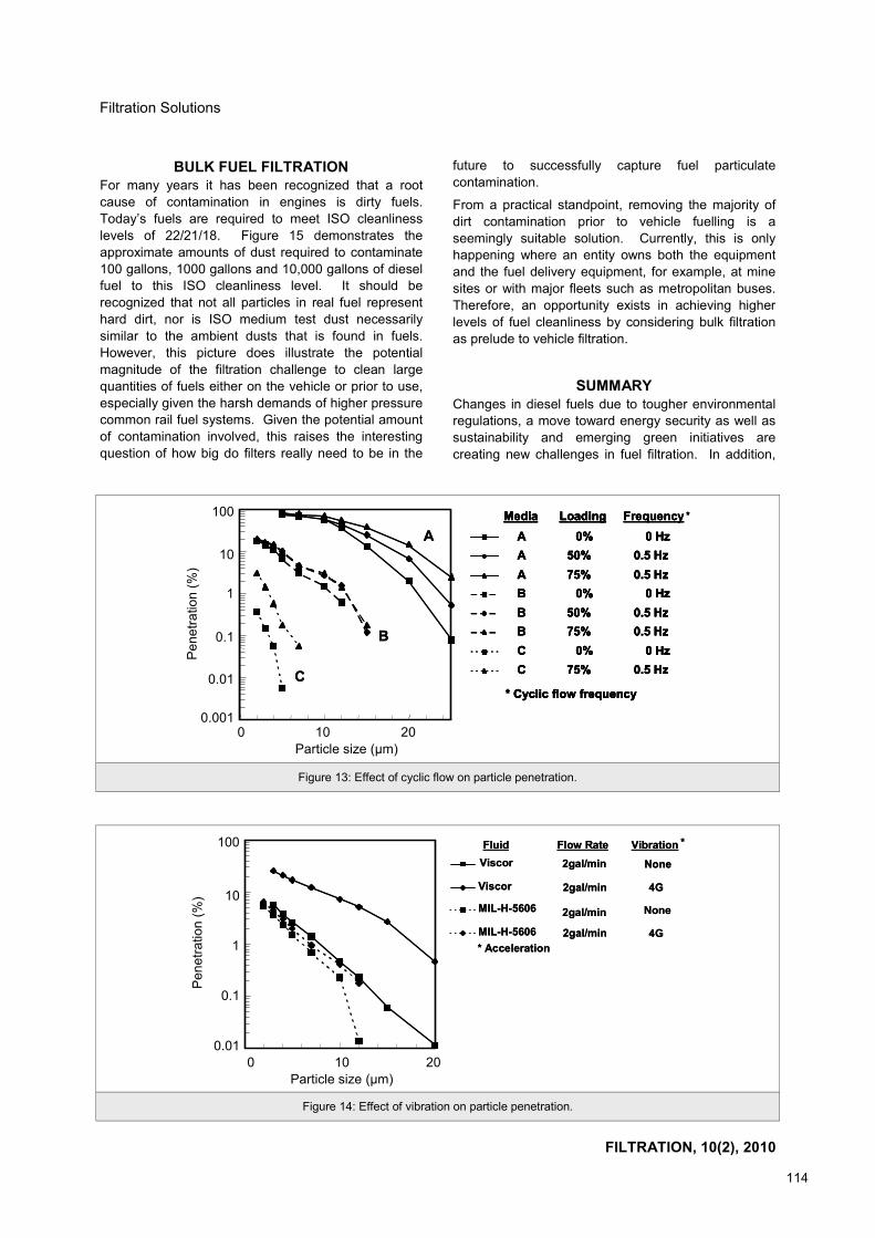
Fuel Filter Performance Under Unsteady Flow Conditions An emerging challenge for filter manufacturers is designing systems which retain filtration performance under actual operating conditions. Historically, filters were evaluated using standard laboratory tests that do not necessarily reflect real world driving conditions, where cyclic flow and vibration are common phenomena. These conditions can degrade a filter's performance causing particle penetration through the filter and recontamination of the fuel before it is injected. The extent of particle penetration depends on cyclic flow frequency, type of filter media and number of particles already loaded onto the filter media as is shown in Figure 1314.
A significant effect on particle penetration was observed under vibration condition using media B with two different test fluids. Particle penetration is plotted against particle size for these two different fluids, MIL-H-5606 hydraulic fluid and Viscor, a surrogate for diesel fuel in Figure 14. The most noticeable difference between these two fluids is the viscosity; MIL-H-5606 is about 6 times more viscous than Viscor. Comparisons are made under two vibration conditions, no vibration and at an acceleration of 4G. Note that high penetration occurs for Viscor under vibration at 4G acceleration. In addition, particle penetration
Figure 8: Typical fuel filters.
Figure 9: Example of metal spin-on (left) and replaceable filter element cartridge (right).
Traditional metal spin-on filter
Reusable plastic housing with non-
metal filter cartridge

FILTRATION, 10(2), 2010
113
Filtration Solutions
during vibration and cyclic flow is more severe for smaller particles (Figures 13 and 14).
Therefore, a robust filter should be designed for maximum engine protection under these operating
conditions. This alone presents another challenge as pointed out by Verdegan15.
Figure 10: Remote mount fuel filtration assembly with optional features and functions.
Integrated Heater
Connector
Head with up to 4 ports
Air Relief Valve
Spin-on Fuel Filter
Spin-on Fuel Filter
Water Separator
Drain Option 1:Clear Water
Collection Bowl
Drain Option 2:Twist&DrainTM
Water Sensor
Drain Option 3:Twist&DrainTM
Manual Priming Pump
Pressure Sensor
Visual Service Indicator
Integrated Heater
Connector
Head with up to 4 ports
Air Relief Valve
Spin-on Fuel Filter
Spin-on Fuel Filter
Water Separator
Drain Option 1:Clear Water
Collection Bowl
Drain Option 2:Twist&DrainTM
Water Sensor
Drain Option 3:Twist&DrainTM
Manual Priming Pump
Pressure Sensor
Visual Service Indicator
Figure 11: A typical fuel systems with both primary and secondary fuel filters.
Injection Pump
Transfer Pump
Fuel Tank
Injectors
Secondary Fuel Filter
Primary Fuel Filter
Figure 12: Donaldson PowerCoreTM fuel processor.
FILTRATION, 10(2), 2010
114
Filtration Solutions
BULK FUEL FILTRATION For many years it has been recognized that a root cause of contamination in engines is dirty fuels. Today’s fuels are required to meet ISO cleanliness levels of 22/21/18. Figure 15 demonstrates the approximate amounts of dust required to contaminate 100 gallons, 1000 gallons and 10,000 gallons of diesel fuel to this ISO cleanliness level. It should be recognized that not all particles in real fuel represent hard dirt, nor is ISO medium test dust necessarily similar to the ambient dusts that is found in fuels. However, this picture does illustrate the potential magnitude of the filtration challenge to clean large quantities of fuels either on the vehicle or prior to use, especially given the harsh demands of higher pressure common rail fuel systems. Given the potential amount of contamination involved, this raises the interesting question of how big do filters really need to be in the
future to successfully capture fuel particulate contamination.
From a practical standpoint, removing the majority of dirt contamination prior to vehicle fuelling is a seemingly suitable solution. Currently, this is only happening where an entity owns both the equipment and the fuel delivery equipment, for example, at mine sites or with major fleets such as metropolitan buses. Therefore, an opportunity exists in achieving higher levels of fuel cleanliness by considering bulk filtration as prelude to vehicle filtration.
SUMMARY
Changes in diesel fuels due to tougher environmental regulations, a move toward energy security as well as sustainability and emerging green initiatives are creating new challenges in fuel filtration. In addition,
Figure 14: Effect of vibration on particle penetration.
Viscor
Viscor
MIL-H-5606
MIL-H-5606
2gal/min None
4G
None
4G
Fluid Flow Rate Vibration *
* Acceleration
2gal/min
2gal/min
2gal/min
Viscor
Viscor
MIL-H-5606
MIL-H-5606
2gal/min None
4G
None
4G
Fluid Flow Rate Vibration *
* Acceleration
2gal/min
2gal/min
2gal/min
Pen
etra
tion
(%) 10
1
0.01
0.1
100
Particle size (μm) 0 10 20
Figure 13: Effect of cyclic flow on particle penetration.
A
B
C
Frequency *
AAAB BBCC
0%50%75%
0%50%75%
0%75%
0 Hz0.5 Hz0.5 Hz
0 Hz0.5 Hz0.5 Hz
0 Hz0.5 Hz
Media Loading
* Cyclic flow frequency
A
B
C
Frequency *
AAAB BBCC
0%50%75%
0%50%75%
0%75%
0 Hz0.5 Hz0.5 Hz
0 Hz0.5 Hz0.5 Hz
0 Hz0.5 Hz
Media Loading
* Cyclic flow frequency
Frequency *
AAAB BBCC
0%50%75%
0%50%75%
0%75%
0 Hz0.5 Hz0.5 Hz
0 Hz0.5 Hz0.5 Hz
0 Hz0.5 Hz
Media Loading
* Cyclic flow frequency
AAAB BBCC
0%50%75%
0%50%75%
0%75%
0 Hz0.5 Hz0.5 Hz
0 Hz0.5 Hz0.5 Hz
0 Hz0.5 Hz
Media Loading
* Cyclic flow frequency
Particle size (μm) 0 10 20
Pen
etra
tion
(%)
10
1
0.01
0.001
0.1
100

FILTRATION, 10(2), 2010
115
Filtration Solutions
evolving engine designs require a much higher level of fuel cleanliness. For the filtration industry this represents emerging challenges for developing next generation fuel filter technology for improved management of particles, water and soft organics. In addition, filter manufacturers are challenged to design filtration systems which retain filtration performance under actual operating conditions of vibration and cyclic flow. As we look into the future we see an increasing need for integration of more features and functions into fuel filtration systems. Understanding the limitations of today’s fuel filtration and emerging industry needs provides an opportunity to address these challenges with innovative technology.
REFERENCES
1. http://m.cnn.com/cnn/ne/tech/detail/92853 2. W.A. Majewski, 2005, Diesel Progress (North
American Edition), 71(12), 18-19. 3. Infineum Insight, 2006, Finding Another Way - The
Challenges of Producing Winter Grade ULSD in
North America, 30,1-3. 4. http://tonto.eia.doe.gov/ask/crudeoil_faqs.asp 5. Diesel Engine Production for NAFTA markets,
presented to the Association of Diesel Specialists, Aug 19th 2004, Rhein Associates.
6. www.epa.gov/OMS/models/analysis/biodsl/p02001. pdf
7. www.nrel.gov/docs/fy05osti/37136.pdf 8. R. Douglas, 2002, Improving fuel system durability,
5th International Filtration Conference, pp.59-67. 9. M.A. Barris, 1995, Total filtration: The influence of
filter selection on engine wear, emissions and performance, SAE Technical Paper Series #952557, SAE Fuels and Lubricants Meeting and Exposition, October 16-19.
10. www.naamsa.co.za/unleaded/WWFC%204%20Sep%202006.pdf, page 50.
11. C. Yang, S. Larsen, and S. Wagner, 2007, Understanding emulsified water filtration from diesel fuels, 8th International Filtration Conference, 2007, 5 pages.
12. C. Yang, L. Senne, S. Larsen and M. Madsen, 2008, ULSD/biodiesel blend and its effect on fuel/water separation, American Filtration and Separation Society Annual Conference, Paper 3-2-3, 12 pages, May 19-22, Valley Forge, USA.
13. G. Kenreck, 2007, Improving biodiesel stability with fuel additives, Biodiesel Magazine, February 2007,134-140.
14. G. LaVallee and P. Johnson, 2003, How flow and vibration affect filtration performance-Inside and outside the laboratory, Machinery Lubrication Magazine, May.
15. B. Verdegan, A. True-Dahl, W. Haberkamp, N. Blizard, D. Genter and E. Quillen, 2008, Filtration solutions for high pressure common rail fuel systems, American Filtration and Separation Society Annual Conference, Paper 1-5-1, 9 pages, May 19-22, Valley Forge, USA.
Figure 15: Amount of ISO medium laboratory test dust re-quired to contaminate fuel to an ISO cleanliness of 22/21/18,
or alternatively which must be filtered out of the given fuel volume.
A NEW METHOD OF MEASURING PORE SIZE DISTRIBUTIONS USING MULTI-MODAL PARTICLE SIZE STANDARDS
Graham R. Rideal1 ([email protected]), Jamie Storey1 and Bernd Schied2
1Whitehouse Scientific, Chester, CH3 7PB, UK. 2BS-Partikel, Wiesbaden, D-65205, Germany.
Porometry has been the traditional method for pore size distribution measurements. However, it has two major limitations: it is not traceable to the Standard Meter and instrument-to-instrument comparisons have been poor. Although challenge testing using traceable reference microspheres fulfils both these criteria, it has hitherto only been able to measure maximum pore sizes. A new ‘Multistandard’ of 10 non-overlapping peaks from 0.1 to 1.5 μm now enables pore size distributions to be made by analysing the relative depletion of the peaks after passing a filter. The technique is only possible because of a high resolution, sub-micron particle size analyser.