emca rc receiver - insa toulousesrv-sicard/microwind/students/... · 2018-10-03 · for our emca tp...
TRANSCRIPT

COX Paul 4 AE -TD A2ELSANKARI Sami December 2009
EMCARC Receiver
Teacher : Etienne Sicard
1
Summary
I ) Overview...................................................................................................................................3
1 ) R/C receiver Basics......................................................................................................3
2 ) R/C receiver architecture............................................................................................4
II ) Our implementation...............................................................................................................5
1 ) Demodulation...............................................................................................................5
2 ) Schimtt Trigger............................................................................................................7
3 ) Decade Counter............................................................................................................8
4 ) Complete System Simulation....................................................................................10
III ) Conclusion...........................................................................................................................12
Appendix .....................................................................................................................................13
2
I ) Overview :
For our EMCA TP project we implemented the major portions of a Remote/Control (R/C) receiver. We used the DSCH and Microwind software to implement and simulate the various digital and analog circuits.
1) R/C Receiver Basics
In the R/C radio world, hand-held transmitters are sold with small receivers to implement remote control operation. The receivers are mounted in scale models, such as helicopters, boats, airplanes and the like. While the transmission methods have evolved over the years from basic crystal-based AM modulation and demodulation to more robust spread spectrum 2.4GHz systems, the basic concept of sending servo positions has remained the same. Each servo position, referred to as a "channel", is driven by the user by a joystick or a switch mounted on the transmitter and establishes the position of a servo in the model. The servos are used to move the control surfaces, regulate motor speeds, fold/unfold landing gear, etc.
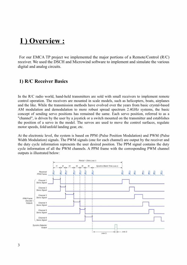
At the electronic level, the system is based on PPM (Pulse Position Modulation) and PWM (Pulse Width Modulation) signals. The PWM signals (one for each channel) are output by the receiver and the duty cycle information represents the user desired position. The PPM signal contains the duty cycle information of all the PWM channels. A PPM frame with the corresponding PWM channel outputs is illustrated below:
3

2 ) R/C Receiver Architecture :
An R/C receiver consists of the two following major blocks:
1. Demodulation - The demodulator circuit is responsible for intercepting the carrier signal from the antenna and recovering the modulated signal. In our project we simulate an AM modulated signal, so demodulation consists of recovering the envelope of the modulated signal. This eliminates the high frequency carrier and results in a signal that can be transformed into a digital pulse train by use of a schmitt trigger.
2. Decade Counter - The recovered pulse train being of the PPM type, a standard decade counter can be used to demultiplex into the separate PWM channels.
4

II ) Our Implementation :
1 ) Demodulation
To demodulate the AM signal we use a standard diode capacitor envelope detector circuit:
We implement this circuit in Microwind using a diode-connected MOS, a polysilicon resistor (in red below; value: x Ohms), and a simulated external capacitor (value: x nF).
Components choice :
We need to choose the values of our components according to the desired value of the time constant of the RC filter.
We want it bigger than the period of the carrier signal, in order to smoothen the signal.
But, as we work with a schmidt trigger behind this component, we don't want the time constant to be too high : the trigger might detect 'high' levels for too long if the signal doesn't decrease fast enough after a pulse.
Working with a 100MHz frequency for the carrier signal, we have a period of 10ns.
The resistor we use has a resistance of 6676 ohms.
We have RC10ns .
Wich gives us : C1.5pF .
After several tests, we settle for a satisfying value of C = 4pF.
5
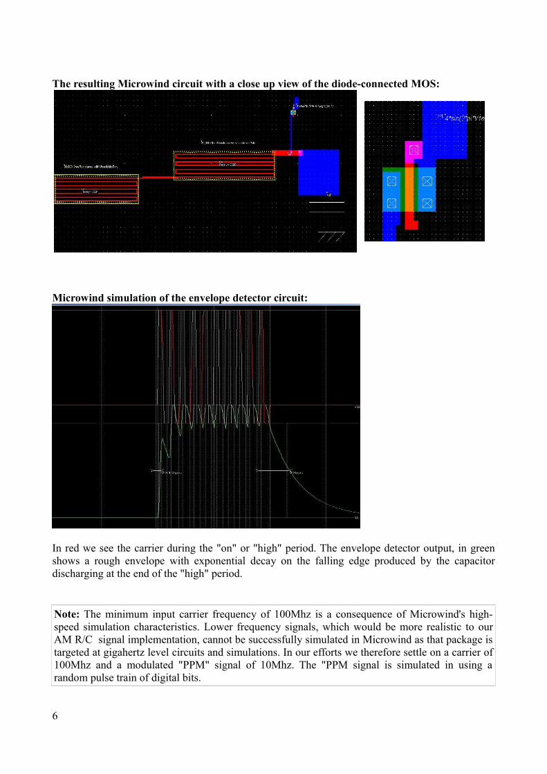
The resulting Microwind circuit with a close up view of the diode-connected MOS:
Microwind simulation of the envelope detector circuit:
In red we see the carrier during the "on" or "high" period. The envelope detector output, in green shows a rough envelope with exponential decay on the falling edge produced by the capacitor discharging at the end of the "high" period.
Note: The minimum input carrier frequency of 100Mhz is a consequence of Microwind's high-speed simulation characteristics. Lower frequency signals, which would be more realistic to our AM R/C signal implementation, cannot be successfully simulated in Microwind as that package is targeted at gigahertz level circuits and simulations. In our efforts we therefore settle on a carrier of 100Mhz and a modulated "PPM" signal of 10Mhz. The "PPM signal is simulated in using a random pulse train of digital bits.
6
2 ) Schmitt Trigger
In order to recover a clean square wave from the quasi-digital output of our envelope detector we use a Schmitt trigger circuit. The Schmitt trigger is a hysteresis device whose output is pure digital.
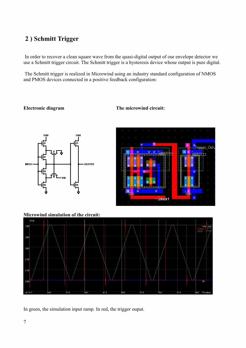
The Schmitt trigger is realized in Microwind using an industry standard configuration of NMOS and PMOS devices connected in a positive feedback configuration:
Electronic diagram The microwind circuit:
Microwind simulation of the circuit:
In green, the simulation input ramp. In red, the trigger ouput.
7

Microwind simulation showing hysteresis curve:
We have 'low-to-high' transitions around 0.6V, and 'high-to-low' transitions around 0.4V. These standards values are satisfying for our project.
3 ) Decade Counter
The decade counter is realized with standard logic. The example circuit, taken from a TI CD4017 datasheet. Because of its complexity, we won't implement it directly in Microwind : we will first replicate and simulate it in DSCH and then generate a Verilog file we will import in Microwind (note : the Verilog file is given in the appendix).
The resulting DSCH circuit:
One button (left) is used as the count input and the other (bottom right) is used as a reset.
8

The resulting Microwind circuit:
Microwind simulation of the circuit:
Simulation of the circuit shows it produces the appropriate counting sequence triggered via falling edges of the input clock.
9

4 ) Complete System Simulation
Putting the envelope detector together with the Schmitt trigger and the decade counter creates the completed R/C receiver.
The final Microwind circuit:
Now, we have to see if the the different parts keep working when they're connected.
10

Final Simulation:
The simulation input is a signal using a carrier of 100MHz frequency, which generates every 'high levels' of random lenght with a frequency of 10MHz.
The simulation shows outputs corresponding to the desired PPM and PWM output formats.
11

III ) Conclusion :
Overall the circuits exhibit the desired behaviors, even if, because of software limitations, we couldn't simulate actual RC frequencies (<100Mhz carrier). The R/C receiver is an interesting project, mixing analog and digital circuits.
There are several parts we didn't have time to test or implement, and that future groups might find interesting to do :
– We didn't simulate any noise. Would be interesting to see how well the circuit performs with the introduction of white and spurious noise.
– We used AM Modulation. FM or PCM would have higher noise immunity but would require more complex demodulation circuits, that would have necessitate way more time. This might be an interesting project for another group next year.
– We didn't simulate the sync portion of the PPM frame. Would need to add a sync detector that resets the decade counter to accomplish this.
12

Appendix - Decade Counter Verilog output from DSCH
// DSCH 3.5 // 30/11/2009 16:49:00 // U:\Windows\Bureau\EMCA\decadecounter.sch
module decadecounter( in4,in5,out1,out2,out3,out4,out5,out6, out7,out8,out9,out10); input in4,in5; output out1,out2,out3,out4,out5,out6,out7,out8; output out9,out10; wire w2,w5,w6,w7,w8,w9,w10,w11; wire w12,w13,w14,w25; dreg #(5) dreg_1(w5,w6,w2,in5,in4); dreg #(5) dreg_2(w7,w8,w5,in5,in4); dreg #(5) dreg_3(w10,w11,w9,in5,in4); dreg #(5) dreg_4(w12,w13,w10,in5,in4); dreg #(5) dreg_5(w14,w2,w12,in5,in4); and #(3) and2_6(out8,w10,w8); and #(3) and2_7(out7,w6,w7); and #(3) and2_8(out10,w14,w13); and #(3) and2_9(out2,w8,w5); and #(3) and2_10(out1,w6,w2); and #(3) and2_11(out3,w11,w7); and #(3) and2_12(out9,w12,w11); and #(3) and2_13(out6,w14,w5); and #(3) and2_14(out4,w13,w10); and #(3) and2_15(out5,w2,w12); and #(3) and2_16(w25,w6,w11); nor #(3) nor2_17(w9,w8,w25); endmodule
// Simulation parameters in Verilog Format always #200 in4=~in4; #400 in5=~in5;
// Simulation parameters // in4 CLK 1 1 // in5 CLK 2 2
13