integrated drive emca-ec-67--co - festo · integrated drive emca- motor with controller, series a...
TRANSCRIPT
Description
Integrated Drive
with CANopen bus
interface
Device and
functional
description
8039971
1603
[8039918]
EMCA-EC-67-...-CO
Integrated Drive

EMCA-EC-67-...-CO
2 Festo – GDCE-EMCA-EC-SY-EN – 1603 – English
Translation of the original instructions
GDCE-EMCA-EC-SY-EN
Adobe Reader®, CANopen®, CiA®, Firefox®, Internet Explorer®, JST® and Tyco Electronics® are
registered trademarks of the respective trademark owners in certain countries.
Identification of hazards and instructions on how to prevent them:
Danger
Immediate dangers which can lead to death or serious injuries
Warning
Hazards that can cause death or serious injuries
Caution
Hazards that can cause minor injuries
Other symbols:
Note
Material damage or loss of function
Recommendations, tips, references to other documentation
Essential or useful accessories
Information on environmentally sound usage
Text designations:
Activities that may be carried out in any order
1. Activities that should be carried out in the order stated
– General lists
Result of an action/References to more detailed information

EMCA-EC-67-...-CO
Festo – GDCE-EMCA-EC-SY-EN – 1603 – English 3
Table of Contents – EMCA-EC-67-...-CO
Instructions on this documentation 7. . . . . . . . . . . . . . . . . . . . . . . . . . . . . . . . . . . . . . . . . . . . . . . . .
Target group 7. . . . . . . . . . . . . . . . . . . . . . . . . . . . . . . . . . . . . . . . . . . . . . . . . . . . . . . . . . . . . . . . . . .
Product identification 7. . . . . . . . . . . . . . . . . . . . . . . . . . . . . . . . . . . . . . . . . . . . . . . . . . . . . . . . . . .
Versions 8. . . . . . . . . . . . . . . . . . . . . . . . . . . . . . . . . . . . . . . . . . . . . . . . . . . . . . . . . . . . . . . . . . . . . .
Service 8. . . . . . . . . . . . . . . . . . . . . . . . . . . . . . . . . . . . . . . . . . . . . . . . . . . . . . . . . . . . . . . . . . . . . . .
Manufacturing time period 8. . . . . . . . . . . . . . . . . . . . . . . . . . . . . . . . . . . . . . . . . . . . . . . . . . . . . . .
Documentation on the product 10. . . . . . . . . . . . . . . . . . . . . . . . . . . . . . . . . . . . . . . . . . . . . . . . . . . .
1 Safety and requirements for product use 11. . . . . . . . . . . . . . . . . . . . . . . . . . . . . . . . . . . . . .
1.1 Safety 11. . . . . . . . . . . . . . . . . . . . . . . . . . . . . . . . . . . . . . . . . . . . . . . . . . . . . . . . . . . . . . . . . .
1.1.1 General safety information 11. . . . . . . . . . . . . . . . . . . . . . . . . . . . . . . . . . . . . . . . . .
1.1.2 Intended use 12. . . . . . . . . . . . . . . . . . . . . . . . . . . . . . . . . . . . . . . . . . . . . . . . . . . . .
1.2 Requirements for product use 13. . . . . . . . . . . . . . . . . . . . . . . . . . . . . . . . . . . . . . . . . . . . . . .
1.2.1 Transport and storage conditions 13. . . . . . . . . . . . . . . . . . . . . . . . . . . . . . . . . . . .
1.2.2 Technical prerequisites 13. . . . . . . . . . . . . . . . . . . . . . . . . . . . . . . . . . . . . . . . . . . .
1.2.3 Training of skilled personnel (requirements of the staff ) 13. . . . . . . . . . . . . . . . . .
1.2.4 Product conformity and certifications 14. . . . . . . . . . . . . . . . . . . . . . . . . . . . . . . . .
2 Product description 15. . . . . . . . . . . . . . . . . . . . . . . . . . . . . . . . . . . . . . . . . . . . . . . . . . . . . . .
2.1 Product overview 15. . . . . . . . . . . . . . . . . . . . . . . . . . . . . . . . . . . . . . . . . . . . . . . . . . . . . . . . .
2.1.1 General features of the product 16. . . . . . . . . . . . . . . . . . . . . . . . . . . . . . . . . . . . . .
2.1.2 Scope of delivery 17. . . . . . . . . . . . . . . . . . . . . . . . . . . . . . . . . . . . . . . . . . . . . . . . .
2.1.3 System structure 18. . . . . . . . . . . . . . . . . . . . . . . . . . . . . . . . . . . . . . . . . . . . . . . . .
2.2 Software for configuration and commissioning 19. . . . . . . . . . . . . . . . . . . . . . . . . . . . . . . . . .
2.2.1 FCT (Festo Configuration Tool) 19. . . . . . . . . . . . . . . . . . . . . . . . . . . . . . . . . . . . . . .
2.2.2 Web server 19. . . . . . . . . . . . . . . . . . . . . . . . . . . . . . . . . . . . . . . . . . . . . . . . . . . . . .
2.3 Connections and display components 20. . . . . . . . . . . . . . . . . . . . . . . . . . . . . . . . . . . . . . . . .
2.4 Drive functions 22. . . . . . . . . . . . . . . . . . . . . . . . . . . . . . . . . . . . . . . . . . . . . . . . . . . . . . . . . . .
2.4.1 Dimension reference system 23. . . . . . . . . . . . . . . . . . . . . . . . . . . . . . . . . . . . . . . .
2.4.2 Homing 26. . . . . . . . . . . . . . . . . . . . . . . . . . . . . . . . . . . . . . . . . . . . . . . . . . . . . . . . .
2.4.3 Jog operation (only via FHPP or with FCT) 34. . . . . . . . . . . . . . . . . . . . . . . . . . . . . .
2.4.4 Teach mode (only via FHPP or with FCT) 35. . . . . . . . . . . . . . . . . . . . . . . . . . . . . . .
2.4.5 Positioning mode 36. . . . . . . . . . . . . . . . . . . . . . . . . . . . . . . . . . . . . . . . . . . . . . . . .
2.4.6 Speed mode 39. . . . . . . . . . . . . . . . . . . . . . . . . . . . . . . . . . . . . . . . . . . . . . . . . . . . .
2.4.7 Force/torque mode 43. . . . . . . . . . . . . . . . . . . . . . . . . . . . . . . . . . . . . . . . . . . . . . .
2.4.8 Stop (halt), Quick-Stop 45. . . . . . . . . . . . . . . . . . . . . . . . . . . . . . . . . . . . . . . . . . . .
2.4.9 Holding brake (only EMCA-EC-...-...-B) 46. . . . . . . . . . . . . . . . . . . . . . . . . . . . . . . . .
2.5 Control (overview) 48. . . . . . . . . . . . . . . . . . . . . . . . . . . . . . . . . . . . . . . . . . . . . . . . . . . . . . . . .
2.6 Operational principle for record selection 49. . . . . . . . . . . . . . . . . . . . . . . . . . . . . . . . . . . . . .
2.6.1 Record switching 49. . . . . . . . . . . . . . . . . . . . . . . . . . . . . . . . . . . . . . . . . . . . . . . . .
2.6.2 Record sequencing 52. . . . . . . . . . . . . . . . . . . . . . . . . . . . . . . . . . . . . . . . . . . . . . . .

EMCA-EC-67-...-CO
4 Festo – GDCE-EMCA-EC-SY-EN – 1603 – English
2.7 Monitoring of the drive behaviour 54. . . . . . . . . . . . . . . . . . . . . . . . . . . . . . . . . . . . . . . . . . . .
2.7.1 Messages 54. . . . . . . . . . . . . . . . . . . . . . . . . . . . . . . . . . . . . . . . . . . . . . . . . . . . . . .
2.7.2 Comparators 58. . . . . . . . . . . . . . . . . . . . . . . . . . . . . . . . . . . . . . . . . . . . . . . . . . . . .
2.7.3 Protective functions 61. . . . . . . . . . . . . . . . . . . . . . . . . . . . . . . . . . . . . . . . . . . . . . .
2.7.4 Error management 62. . . . . . . . . . . . . . . . . . . . . . . . . . . . . . . . . . . . . . . . . . . . . . . .
2.7.5 Diagnostic memory 63. . . . . . . . . . . . . . . . . . . . . . . . . . . . . . . . . . . . . . . . . . . . . . .
2.8 Interfaces 64. . . . . . . . . . . . . . . . . . . . . . . . . . . . . . . . . . . . . . . . . . . . . . . . . . . . . . . . . . . . . . .
2.8.1 Parameterisation interface [X1] (Ethernet interface) 64. . . . . . . . . . . . . . . . . . . . . .
2.8.2 Control interface [X2], [X3] (fieldbus) 65. . . . . . . . . . . . . . . . . . . . . . . . . . . . . . . . . .
2.8.3 STO interface [X6] 65. . . . . . . . . . . . . . . . . . . . . . . . . . . . . . . . . . . . . . . . . . . . . . . . .
2.8.4 Functions of the base inputs/outputs 66. . . . . . . . . . . . . . . . . . . . . . . . . . . . . . . . .
3 Mounting 71. . . . . . . . . . . . . . . . . . . . . . . . . . . . . . . . . . . . . . . . . . . . . . . . . . . . . . . . . . . . . . .
3.1 Dimensions 71. . . . . . . . . . . . . . . . . . . . . . . . . . . . . . . . . . . . . . . . . . . . . . . . . . . . . . . . . . . . . .
3.2 Performing mounting 72. . . . . . . . . . . . . . . . . . . . . . . . . . . . . . . . . . . . . . . . . . . . . . . . . . . . . .
4 Installation 74. . . . . . . . . . . . . . . . . . . . . . . . . . . . . . . . . . . . . . . . . . . . . . . . . . . . . . . . . . . . . .
4.1 Safety instructions 74. . . . . . . . . . . . . . . . . . . . . . . . . . . . . . . . . . . . . . . . . . . . . . . . . . . . . . . .
4.2 EMC-compliant wiring 75. . . . . . . . . . . . . . . . . . . . . . . . . . . . . . . . . . . . . . . . . . . . . . . . . . . . . .
4.3 Parameterisation interface [X1] 76. . . . . . . . . . . . . . . . . . . . . . . . . . . . . . . . . . . . . . . . . . . . . .
4.4 Control interface [X1], [3] 78. . . . . . . . . . . . . . . . . . . . . . . . . . . . . . . . . . . . . . . . . . . . . . . . . . .
4.4.1 Control interface EMCA-...-CO (CANopen) 78. . . . . . . . . . . . . . . . . . . . . . . . . . . . . .
4.5 Connection of the plug connectors [X4] ... [X10] 80. . . . . . . . . . . . . . . . . . . . . . . . . . . . . . . . .
4.5.1 Power supply [X4] 83. . . . . . . . . . . . . . . . . . . . . . . . . . . . . . . . . . . . . . . . . . . . . . . . .
4.5.2 Braking resistor [X5] 85. . . . . . . . . . . . . . . . . . . . . . . . . . . . . . . . . . . . . . . . . . . . . . .
4.5.3 STO interface [X6] 86. . . . . . . . . . . . . . . . . . . . . . . . . . . . . . . . . . . . . . . . . . . . . . . . .
4.5.4 Limit or reference switch [X7], [X8] 87. . . . . . . . . . . . . . . . . . . . . . . . . . . . . . . . . . .
4.5.5 I/O interface [X9] 88. . . . . . . . . . . . . . . . . . . . . . . . . . . . . . . . . . . . . . . . . . . . . . . . .
4.5.6 External battery [X10] 89. . . . . . . . . . . . . . . . . . . . . . . . . . . . . . . . . . . . . . . . . . . . . .
4.6 Requirements for ensuring IP degree of protection 90. . . . . . . . . . . . . . . . . . . . . . . . . . . . . . .
5 Commissioning 91. . . . . . . . . . . . . . . . . . . . . . . . . . . . . . . . . . . . . . . . . . . . . . . . . . . . . . . . . . .
5.1 Notes on commissioning 91. . . . . . . . . . . . . . . . . . . . . . . . . . . . . . . . . . . . . . . . . . . . . . . . . . . .
5.2 FCT (Festo Configuration Tool) 91. . . . . . . . . . . . . . . . . . . . . . . . . . . . . . . . . . . . . . . . . . . . . . .
5.2.1 Installing FCT 91. . . . . . . . . . . . . . . . . . . . . . . . . . . . . . . . . . . . . . . . . . . . . . . . . . . .
5.2.2 Starting the FCT 92. . . . . . . . . . . . . . . . . . . . . . . . . . . . . . . . . . . . . . . . . . . . . . . . . .
5.2.3 Notes on commissioning with FCT 92. . . . . . . . . . . . . . . . . . . . . . . . . . . . . . . . . . . .
5.3 Network connection via Ethernet 94. . . . . . . . . . . . . . . . . . . . . . . . . . . . . . . . . . . . . . . . . . . . .
5.3.1 Displaying or changing network configuration 95. . . . . . . . . . . . . . . . . . . . . . . . . .
5.3.2 Security in the network 96. . . . . . . . . . . . . . . . . . . . . . . . . . . . . . . . . . . . . . . . . . . .
5.4 Master control 98. . . . . . . . . . . . . . . . . . . . . . . . . . . . . . . . . . . . . . . . . . . . . . . . . . . . . . . . . . . .
5.5 Online connection with the web server 100. . . . . . . . . . . . . . . . . . . . . . . . . . . . . . . . . . . . . . . .

EMCA-EC-67-...-CO
Festo – GDCE-EMCA-EC-SY-EN – 1603 – English 5
5.6 Commissioning steps 102. . . . . . . . . . . . . . . . . . . . . . . . . . . . . . . . . . . . . . . . . . . . . . . . . . . . . .
5.6.1 Configuration and parameterisation 102. . . . . . . . . . . . . . . . . . . . . . . . . . . . . . . . . .
5.6.2 Checking STO function 103. . . . . . . . . . . . . . . . . . . . . . . . . . . . . . . . . . . . . . . . . . . . .
5.6.3 Check signal characteristics of the limit and reference switch 103. . . . . . . . . . . . . .
5.6.4 Providing required signals (digital I/Os) 103. . . . . . . . . . . . . . . . . . . . . . . . . . . . . . .
5.6.5 Checking direction of rotation/travel direction 104. . . . . . . . . . . . . . . . . . . . . . . . . .
5.6.6 Carrying out homing 105. . . . . . . . . . . . . . . . . . . . . . . . . . . . . . . . . . . . . . . . . . . . . . .
5.6.7 Testing positioning behaviour (test mode) 105. . . . . . . . . . . . . . . . . . . . . . . . . . . . .
5.6.8 Optimising controller setting (optional) 105. . . . . . . . . . . . . . . . . . . . . . . . . . . . . . . .
5.6.9 Performing fieldbus configuration and testing control profile 105. . . . . . . . . . . . . .
5.6.10 Completing commissioning 106. . . . . . . . . . . . . . . . . . . . . . . . . . . . . . . . . . . . . . . . .
5.7 Saving or loading parameter file 107. . . . . . . . . . . . . . . . . . . . . . . . . . . . . . . . . . . . . . . . . . . . . .
5.8 Notes for operation 108. . . . . . . . . . . . . . . . . . . . . . . . . . . . . . . . . . . . . . . . . . . . . . . . . . . . . . . .
5.8.1 Maximum writing cycles of the flash memory 108. . . . . . . . . . . . . . . . . . . . . . . . . . .
6 Diagnostics and fault clearance 109. . . . . . . . . . . . . . . . . . . . . . . . . . . . . . . . . . . . . . . . . . . . .
6.1 Access to the diagnostic memory 109. . . . . . . . . . . . . . . . . . . . . . . . . . . . . . . . . . . . . . . . . . . . .
6.2 Diagnostics via LED 111. . . . . . . . . . . . . . . . . . . . . . . . . . . . . . . . . . . . . . . . . . . . . . . . . . . . . . . .
6.2.1 Behaviour in the switch-on phase 111. . . . . . . . . . . . . . . . . . . . . . . . . . . . . . . . . . . .
6.2.2 Behaviour in the operating phase 111. . . . . . . . . . . . . . . . . . . . . . . . . . . . . . . . . . . .
6.2.3 Behaviour during waving 112. . . . . . . . . . . . . . . . . . . . . . . . . . . . . . . . . . . . . . . . . . .
6.2.4 Behaviour with errors in the firmware update phase 112. . . . . . . . . . . . . . . . . . . . .
6.2.5 Bus-specific LED 112. . . . . . . . . . . . . . . . . . . . . . . . . . . . . . . . . . . . . . . . . . . . . . . . . .
6.3 Diagnostic messages, causes and remedies 113. . . . . . . . . . . . . . . . . . . . . . . . . . . . . . . . . . . .
6.3.1 Explanations of the diagnostic messages 113. . . . . . . . . . . . . . . . . . . . . . . . . . . . . .
6.3.2 Diagnostic messages with instructions for fault clearance 114. . . . . . . . . . . . . . . . .
6.4 Problems with the Ethernet connection 129. . . . . . . . . . . . . . . . . . . . . . . . . . . . . . . . . . . . . . . .
6.5 Other problems and remedies 130. . . . . . . . . . . . . . . . . . . . . . . . . . . . . . . . . . . . . . . . . . . . . . .
7 Maintenance, care, repair and replacement 131. . . . . . . . . . . . . . . . . . . . . . . . . . . . . . . . . . . .
7.1 Maintenance and care 131. . . . . . . . . . . . . . . . . . . . . . . . . . . . . . . . . . . . . . . . . . . . . . . . . . . . . .
7.2 Disassembly 132. . . . . . . . . . . . . . . . . . . . . . . . . . . . . . . . . . . . . . . . . . . . . . . . . . . . . . . . . . . . .
7.3 Repair 133. . . . . . . . . . . . . . . . . . . . . . . . . . . . . . . . . . . . . . . . . . . . . . . . . . . . . . . . . . . . . . . . . .
7.4 Replacement and disposal 133. . . . . . . . . . . . . . . . . . . . . . . . . . . . . . . . . . . . . . . . . . . . . . . . . .
7.4.1 Disposal 133. . . . . . . . . . . . . . . . . . . . . . . . . . . . . . . . . . . . . . . . . . . . . . . . . . . . . . . .
A Technical appendix 134. . . . . . . . . . . . . . . . . . . . . . . . . . . . . . . . . . . . . . . . . . . . . . . . . . . . . . . .
A.1 Technical data 134. . . . . . . . . . . . . . . . . . . . . . . . . . . . . . . . . . . . . . . . . . . . . . . . . . . . . . . . . . . .
A.1.1 General technical data 134. . . . . . . . . . . . . . . . . . . . . . . . . . . . . . . . . . . . . . . . . . . . .
A.1.2 Product conformity and certifications 134. . . . . . . . . . . . . . . . . . . . . . . . . . . . . . . . .
A.1.3 Mechanical data 135. . . . . . . . . . . . . . . . . . . . . . . . . . . . . . . . . . . . . . . . . . . . . . . . . .
A.1.4 Operating and environmental conditions 135. . . . . . . . . . . . . . . . . . . . . . . . . . . . . . .

EMCA-EC-67-...-CO
6 Festo – GDCE-EMCA-EC-SY-EN – 1603 – English
A.1.5 Data on the integrated motor 136. . . . . . . . . . . . . . . . . . . . . . . . . . . . . . . . . . . . . . .
A.1.6 Data on the integrated rotary position encoder 137. . . . . . . . . . . . . . . . . . . . . . . . .
A.1.7 Holding brake (only EMCA-EC-...-...-B) 137. . . . . . . . . . . . . . . . . . . . . . . . . . . . . . . . .
A.1.8 Parameterisation interface [X1] 137. . . . . . . . . . . . . . . . . . . . . . . . . . . . . . . . . . . . . .
A.1.9 Control interface [X2], [X3] 138. . . . . . . . . . . . . . . . . . . . . . . . . . . . . . . . . . . . . . . . . .
A.1.10 Power supply [X4] 138. . . . . . . . . . . . . . . . . . . . . . . . . . . . . . . . . . . . . . . . . . . . . . . . .
A.1.11 Braking resistor [X5] 138. . . . . . . . . . . . . . . . . . . . . . . . . . . . . . . . . . . . . . . . . . . . . . .
A.1.12 STO interface [X6] 139. . . . . . . . . . . . . . . . . . . . . . . . . . . . . . . . . . . . . . . . . . . . . . . . .
A.1.13 Reference or limit switch [X7], [X8] 139. . . . . . . . . . . . . . . . . . . . . . . . . . . . . . . . . . .
A.1.14 I/O interface [X9] 140. . . . . . . . . . . . . . . . . . . . . . . . . . . . . . . . . . . . . . . . . . . . . . . . .
A.1.15 Connection for external battery [X10] (only EMCA-EC-67-...-1TM) 141. . . . . . . . . . .
A.1.16 Materials 141. . . . . . . . . . . . . . . . . . . . . . . . . . . . . . . . . . . . . . . . . . . . . . . . . . . . . . . .
B Glossary 142. . . . . . . . . . . . . . . . . . . . . . . . . . . . . . . . . . . . . . . . . . . . . . . . . . . . . . . . . . . . . . . .
Index 143. . . . . . . . . . . . . . . . . . . . . . . . . . . . . . . . . . . . . . . . . . . . . . . . . . . . . . . . . . . . . . . . . . . . . . . .
EMCA-EC-67-...-CO
Festo – GDCE-EMCA-EC-SY-EN – 1603 – English 7
Instructions on this documentation
This documentation (GDCE-EMCA-EC-SY-...) describes the functions, commissioning and error mes
sages of the integrated drive EMCA.
Target group
This documentation is intended exclusively for technicians trained in control and automation techno
logy who have experience in installation, commissioning, parameterisation, programming and dia
gnostics of electrical drive systems.
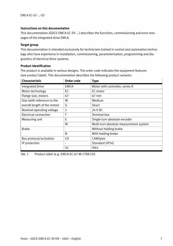
Product identification
The product is available in various designs. The order code indicates the equipment features
(see product label). This documentation describes the following product variants:
Characteristic Order code Type
Integrated Drive EMCA- Motor with controller, series A
Motor technology EC- EC motor
Flange size, motors 67- 67 mm
Size (with reference to the
overall length of the motor)
M- Medium
S- Short
Nominal operating voltage 1 24 V DC
Electrical connection T Terminal box
Measuring unit E Single-turn absolute encoder
M Multi-turn absolute measurement system
Brake - Without holding brake
B- With holding brake
Bus protocol/activation CO CANOpen
IP protection - Standard (IP54)
S1 IP65
Tab. 1 Product label (e.g. EMCA-EC-67-M-1TEB-CO)

EMCA-EC-67-...-CO
8 Festo – GDCE-EMCA-EC-SY-EN – 1603 – English
Product label – example Meaning Example
EMCA-EC-67-S-1TE-CO
8034238 FN98 123456789...
nG : 3100 rpm
MN : 0.37 Nm
UN : 24 V DC
IN : 5.7 A
IP54
Order code EMCA-EC-67-S-1TE-CO
Part number 8034238
Serial number FN98
Product key 123456789...
Nominal rotary speed
nG
[rpm] 3100
Nominal torque MN [Nm] 0.37
Nominal voltage UN [V DC] 24
Nominal current IN [A] 5.7
Degree of protection IP54
Tab. 2 Product label – example EMCA-EC-67-S-1TE-CO
Information on the product key and the data matrix code www.festo.com/pk.
Versions
For current versions of the firmware, FCT software and user documentation on the product
www.festo.com/sp.
This document refers to the following versions:
– EMCA with an order code specified in Tab. 1 with revision 1.0.0 or later
– Firmware version 1.0 or later
– FCT plug-in EMCA version 1.0 or later
The product key of the product can be entered as a search term in the Festo Support Portal to determ
ine the revision of the device ( www.festo.com/sp).
Note
Before using a newer firmware version, check whether a newer version of the FCT plug-
in and a new user documentation are available for it ( www.festo.com/sp).
Service
Consult the regional Festo contact if you have technical problems.
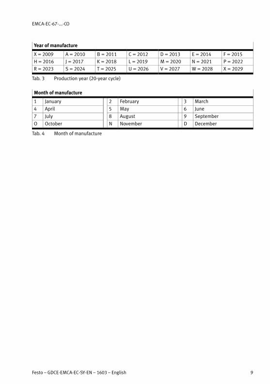
Manufacturing time period
In the product labelling, the first 2 characters of the serial number indicate the manufacturing date in
encrypted form ( Tab. 2). The letter specifies the year of manufacture and the character following it
(number or letter) the month of manufacture.
EMCA-EC-67-...-CO
Festo – GDCE-EMCA-EC-SY-EN – 1603 – English 9
Year of manufacture
X = 2009 A = 2010 B = 2011 C = 2012 D = 2013 E = 2014 F = 2015
H = 2016 J = 2017 K = 2018 L = 2019 M = 2020 N = 2021 P = 2022
R = 2023 S = 2024 T = 2025 U = 2026 V = 2027 W = 2028 X = 2029
Tab. 3 Production year (20-year cycle)
Month of manufacture
1 January 2 February 3 March
4 April 5 May 6 June
7 July 8 August 9 September
O October N November D December
Tab. 4 Month of manufacture
EMCA-EC-67-...-CO
10 Festo – GDCE-EMCA-EC-SY-EN – 1603 – English
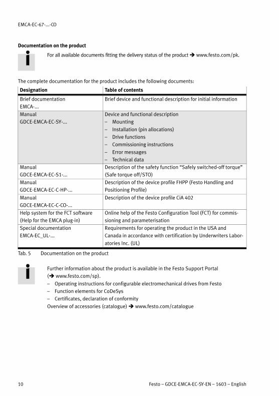
Documentation on the product
For all available documents fitting the delivery status of the product www.festo.com/pk.
The complete documentation for the product includes the following documents:
Designation Table of contents
Brief documentation
EMCA-...
Brief device and functional description for initial information
Manual
GDCE-EMCA-EC-SY-...
Device and functional description
– Mounting
– Installation (pin allocations)
– Drive functions
– Commissioning instructions
– Error messages
– Technical data
Manual
GDCE-EMCA-EC-S1-...
Description of the safety function “Safely switched-off torque”
(Safe torque off/STO)
Manual
GDCE-EMCA-EC-C-HP-...
Description of the device profile FHPP (Festo Handling and
Positioning Profile)
Manual
GDCE-EMCA-EC-C-CO-...
Description of the device profile CiA 402
Help system for the FCT software
(Help for the EMCA plug-in)
Online help of the Festo Configuration Tool (FCT) for commis
sioning and parameterisation
Special documentation
EMCA-EC_UL-...
Requirements for operating the product in the USA and
Canada in accordance with certification by Underwriters Labor
atories Inc. (UL)
Tab. 5 Documentation on the product
Further information about the product is available in the Festo Support Portal
( www.festo.com/sp).
– Operating instructions for configurable electromechanical drives from Festo
– Function elements for CoDeSys
– Certificates, declaration of conformity
Overview of accessories (catalogue) www.festo.com/catalogue
1 Safety and requirements for product use
Festo – GDCE-EMCA-EC-SY-EN – 1603 – English 11
1 Safety and requirements for product use
1.1 Safety
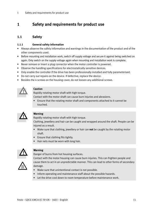
1.1.1 General safety information
Always observe the safety information and warnings in the documentation of the product and of the
other components used.
Before mounting and installation work, switch off supply voltage and secure it against being switched on
again. Only switch on the supply voltage again when mounting and installation work is complete.
Never remove or insert a plug connector when the motor controller is powered.
Observe the handling specifications for electrostatically sensitive devices.
Only enable the controller if the drive has been professionally installed and fully parameterised.
Do not carry out repairs on the device. If defective, replace the device.
Besides the 4 screws on the housing cover, do not loosen any additional screws.
Caution
Rapidly rotating motor shaft with high torque.
Contact with the motor shaft can cause burn injuries and abrasions.
Ensure that the rotating motor shaft and components attached to it cannot be
touched.
Warning
Rapidly rotating motor shaft with high torque.
Clothing, jewellery and hair can be caught and wrapped around the shaft. People can be
injured as a result.
Make sure that clothing, jewellery or hair can not be caught by the rotating motor
shaft.
Ensure that clothing fits tightly.
Hair nets must be worn with long hair.
Warning
Danger of burns from hot housing surfaces.
Contact with the motor housing can cause burn injuries. This can frighten people and
cause them to act in an unpredictable manner. This can lead to other forms of secondary
damage.
Make sure that unintentional contact is not possible.
Inform operating and maintenance staff about the possible hazards.
Let the drive cool down to room temperature before maintenance work.
1 Safety and requirements for product use
12 Festo – GDCE-EMCA-EC-SY-EN – 1603 – English
Note
Gas formation with fire risk.
If cleaning agents make contact with the hot surface of the motor, gases can form and
ignite.
Prior to cleaning work, let the drive cool down to room temperature.
Pay attention to the instructions for use of the cleaning agent.
1.1.2 Intended use
The product is intended for driving and controlling electromechanical drives. The integrated electronics
permit regulation of torque (current), rotational speed and position of the mounted drive. The product
is intended for installation in a machine.
Depending on the order, the product contains a motor with holding brake (EMCA-EC-...-...B). The hold
ing brake is intended to hold the motor position/drive position in standstill.
Use exclusively:
– In perfect technical condition
– In original status without unauthorised modifications; only the expansions described in the docu
mentation supplied with the product are permitted
– Within the limits of the product defined by the technical data ( Appendix A.1)
– In an industrial environment
The product is intended for use in industrial environments. Outside of industrial environments, e.g. in
commercial and mixed-residential areas, actions to suppress interference may have to be taken.
In the event of damage caused by unauthorised manipulation or other than intended use, the guaran
tee is invalidated and the manufacturer is not liable for damages.
The product supports the safety function “safe torque off ” (STO) (Safe torque off/STO).
The STO safety function (Safe torque off ) is described in detail in the document
GDCE-EMCA-EC-S1-.... The safety function STO should only be used in the manner
described in this document. For additional information Description of STO safety
function, GDCE-EMCA-EC-S1-....

1 Safety and requirements for product use
Festo – GDCE-EMCA-EC-SY-EN – 1603 – English 13
1.2 Requirements for product use
Provide the complete product documentation to the following personnel:
– the design engineer and the installer of the machine or system
– the personnel responsible for commissioning
Keep the documentation safe throughout the entire product lifecycle.
Always comply with the specifications of the documentation. Also consider the documentation for
the other components and modules (e.g. for the gearbox or axial kit).
Take into consideration the legal regulations for the respective location as well as:
– regulations and standards
– regulations of the testing organisations and insurers
– national specifications
For correct and safe use of the STO function:
Observe the additional notes in the description for the GDCE-EMCA-EC-S1-....
1.2.1 Transport and storage conditions
Protect the product during transport and storage from excessive stress factors. Excessive stress
factors include:
– mechanical stresses
– impermissible temperatures
– moisture
– aggressive atmospheres
Store and transport the product in its original packaging. The original packaging offers sufficient
protection from typical stresses.
1.2.2 Technical prerequisites
For correct and safe use of the product:
Comply with the connection and ambient conditions of the product ( Appendix A.1) and all con
nected components specified in the technical data. Compliance with the limit values and load limits
permits operation of the product in compliance with the relevant safety regulations.
Observe the notes and warnings in this documentation.
1.2.3 Training of skilled personnel (requirements of the staff )
The following steps must only be carried out by qualified specialists:
– Mounting
– Installation
– Commissioning
The trained personnel must be familiar with the topics:
– electrical control technology
– applicable regulations for operating safety-engineering systems
– applicable regulations for accident prevention and operational reliability
– documentation for the product

1 Safety and requirements for product use
14 Festo – GDCE-EMCA-EC-SY-EN – 1603 – English
1.2.4 Product conformity and certifications
For standards and test values which the product must comply with Technical data chapter
(AppendixA.1). Product-relevant EU directives Declaration of conformity.
For certificates and the declaration of conformity for this product www.festo.com/sp.
Certain configurations of the product have been certified by Underwriters Laboratories Inc. (UL) for the
USA and Canada. These configurations are marked with the following symbol.
UL Recognized Component Mark for Canada and the United States
Only for connection to an NEC Class 2 supply.
Raccorder Uniqement a un circuit de Class 2.
Rules for observing the UL certification can be found in the separate UL special documentation. The
technical data stated therein take priority. The technical data in this documentation can show values
deviating from this.
Specified directives and standards
Version statuses
2006/42/EC DIN EN 60068-2-6:2008-10
2014/30/EU DIN EN 60068227:201002
Tab. 1.1 Version statuses of the directives and standards specified in the document
2 Product description
Festo – GDCE-EMCA-EC-SY-EN – 1603 – English 15
2 Product description
2.1 Product overview
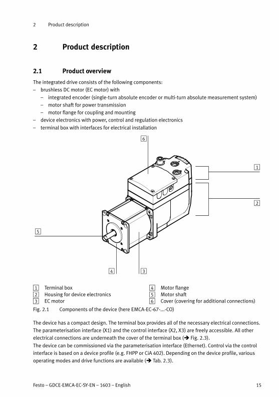
The integrated drive consists of the following components:
– brushless DC motor (EC motor) with
– integrated encoder (single-turn absolute encoder or multi-turn absolute measurement system)
– motor shaft for power transmission
– motor flange for coupling and mounting
– device electronics with power, control and regulation electronics
– terminal box with interfaces for electrical installation
1
2
34
5
6
1 Terminal box
2 Housing for device electronics
3 EC motor
4 Motor flange
5 Motor shaft
6 Cover (covering for additional connections)
Fig. 2.1 Components of the device (here EMCA-EC-67-...-CO)
The device has a compact design. The terminal box provides all of the necessary electrical connections.
The parameterisation interface (X1) and the control interface (X2, X3) are freely accessible. All other
electrical connections are underneath the cover of the terminal box ( Fig. 2.3).
The device can be commissioned via the parameterisation interface (Ethernet). Control via the control
interface is based on a device profile (e.g. FHPP or CiA 402). Depending on the device profile, various
operating modes and drive functions are available ( Tab. 2.3).

2 Product description
16 Festo – GDCE-EMCA-EC-SY-EN – 1603 – English
2.1.1 General features of the product
Feature Description
EC motor Brushless DC motor with:
– integrated encoder (single-turn absolute encoder or multi-turn
absolute measurement system)
– holding brake (optional)
Electronics – Output stage for motor activation and control
– Nominal voltage 24 V DC
– Integrated brake chopper – braking resistor1) (accessories)
must be connected externally
– Integrated electronic controls, e.g. with:
– controller for position, speed and current regulation
– Ethernet interface (parameterisation interface)
– EMCA-...-CO: CAN interface (control interface; CANopen
communication profile; FHPP and CiA 402 device profile)
– safety function STO (safe torque off )
– diagnostic memory
Power supply Shared load and logic power supply 24 V DC
Commissioning Via the Ethernet interface with FCT
Diagnostics LED indicator, web server, FCT software, via bus/network
Web server Software integrated into the device with the following functions:
– display of status information and I/O data
– readout of the diagnostics memory
– uploading and downloading of a parameters file for easy device
replacement
Call via web browser (Internet Explorer or Firefox)
1) Available separately as an accessory ( www.festo.com/catalogue)
Tab. 2.1 Overview of product features EMCA
2 Product description
Festo – GDCE-EMCA-EC-SY-EN – 1603 – English 17
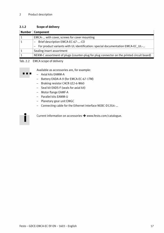
2.1.2 Scope of delivery
Number Component
1 EMCA-... with cover, screws for cover mounting
1 – Brief description EMCA-EC-67-...-CO
– For product variants with UL identification: special documentation EMCA-EC_UL-...
1 Sealing insert assortment
1 NEKM-C assortment of plugs (counter-plug for plug connector on the printed circuit board)
Tab. 2.2 EMCA scope of delivery
Available as accessories are, for example:
– Axial kits EAMM-A
– Battery EADA-A-9 (for EMCA-EC-67-1TM)
– Braking resistor CACR-LE2-6-W60
– Seal kit EADS-F (seals for axial kit)
– Motor flange EAMF-A
– Parallel kits EAMM-U
– Planetary gear unit EMGC
– Connecting cable for the Ethernet interface NEBC-D12G4-...
Current information on accessories www.festo.com/catalogue.
2 Product description
18 Festo – GDCE-EMCA-EC-SY-EN – 1603 – English
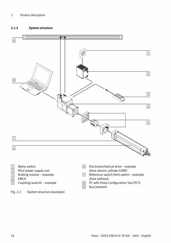
2.1.3 System structure
5
6
2
3
4
1
7
8
9
1 Mains switch
2 PELV power supply unit
3 Braking resistor – example
4 EMCA
5 Coupling/axial kit – example
6 Electromechanical drive – example
(here electric cylinder ESBF)
7 Reference switch/limit switch – example
(here without)
8 PC with Festo Configuration Tool (FCT)
9 Bus/network
Fig. 2.2 System structure (example)
2 Product description
Festo – GDCE-EMCA-EC-SY-EN – 1603 – English 19
2.2 Software for configuration and commissioning
2.2.1 FCT (Festo Configuration Tool)
The Festo Configuration Tool (FCT) is the Windows-based software platform for configuration, paramet
erisation and commissioning of different components and devices from Festo. FCT also allows configur
ation and commissioning of the integrated drive EMCA.
The FCT consists of the following components:
– a framework as program start and entry point with uniform project and data management for all
supported types of equipment
– one plug-in for the special requirements of each device type (e.g. EMCA) with the necessary descrip
tions and dialogues
The plug-ins are managed and started from the framework. The EMCA plug-in supports performance of
all the steps necessary for configuration, parameterisation and commissioning of the product. Paramet
erisation of the product can be executed offline (without connection to the EMCA) on a PC. This enables
preparation for the actual commissioning, for example, in the planning office when a system is being
planned.
The allows the following functions, for example:
– administration of the following data/files via the Ethernet interfaces (online):
– device data (parameterisation)
– firmware file (Firmware Download)
– manual operation (e.g. jogging, teaching)
– diagnostics
– recording of measurement data
– automatic calculation of the controller data for selected motor-gear unit-axis combinations from
Festo
– manual precision adjustment of the controller data
For further information on commissioning with FCT Chapter 5. Detailed information
about FCT Help system for the software.
2.2.2 Web server
A web server is integrated into the device. The web server provides read access to a dynamic English-
language website for the device. The website of the web server allows the following functions:
– display of the status information of the device (e.g. current position, target position)
– display of the signal statuses of digital I/Os
– display of the I/O data of the FHPP protocol
– readout and display of the diagnostic memory
– uploading of a parameter file - e.g. to save current settings on the PC
– downloading of a parameter file - e.g. to restore settings
– activation of LED flashing to identify the device optically
The DHCP server (DHCP stands for Dynamic Host Configuration Protocol) of the device is activated in
the factory setting, and the device has the following IP address: 192.168.178.1.

2 Product description
20 Festo – GDCE-EMCA-EC-SY-EN – 1603 – English
2.3 Connections and display components
EMCA-EC-67-...-CO (CANopen bus interface)
1 2
3
4
5
6
78
9
aJ
1 [X1]: Parameterisation interface
(socket M12)
2 LED light guide (6x) – 3 used
3 [X3]: CAN OUT – continuation line
(socket M12)
4 Cable throughfeed of the terminal box (each
here with seal insert)
5 Through-hole for mounting (4x)
6 Plug connectors ( Fig. 2.4)
7 Mounting thread (4x) thread M4
8 Motor flange
9 Shaft
aJ [X2]: CAN IN – incoming line
(plug connector M12)
Fig. 2.3 Control sections and connections EMCA-EC-67-...-CO

2 Product description
Festo – GDCE-EMCA-EC-SY-EN – 1603 – English 21
The following plug connectors are below the cover:
1
2
3 4 5 6 7
89
1 [X4]: Power supply
2 [X5]: Braking resistor
3 DIP switch (terminating resistor for CAN bus)
4 [X10]: External battery
(only EMCA-EC-...-1TM)
5 [X6]: STO interface (safe torque off )
6 [X7]: Reference or limit switch 11)
7 [X8]: Reference or limit switch 21)
8 [X9]: I/O interface
9 FU connection (flat plug)
1) Switch function (reference or limit switch) and switch type (normally closed or normally open), configurable with FCT
Fig. 2.4 Electrical connections under the cover

2 Product description
22 Festo – GDCE-EMCA-EC-SY-EN – 1603 – English
2.4 Drive functions
The integrated drive EMCA supports a number of drive functions. The available drive functions depend
on the device profile used (e.g. FHPP, CiA 402).
Drive functions Brief description Device
profile
Homing
( Chapter 2.4.2)
Performance of homing in order to determine the reference
point
– FHPP
– CiA 402
Jog operation
( Chapter 2.4.3)
Manual operation of the drive in the positioning mode – FHPP
Teach mode
( Chapter 2.4.4)
Transfer of the current position (e.g. as a target position in
the selected record)
– FHPP
Positioning mode
( Chapter 2.4.5)
The EMCA calculates the positioning curve (point-to-point posi
tioning) from the specified parameters (e.g. target position,
acceleration, speed) and controls the motor accordingly.
– FHPP
– CiA 402
Speed mode
( Chapter 2.4.6)
Processing of tasks with speed setpoints; the speed regulat
or and the current regulator process deviation between the
“speed setpoint” and the “actual value for rotational speed”.
– FHPP
– CiA 402
Force/torque mode
( Chapter 2.4.7)
The current regulator processes deviation between the set
point and the actual value for current.
– FHPP
– CiA 402
Tab. 2.3 Drive functions
For additional information on the device profiles Description for the respective device
profile. For information on FCT Help on the EMCA plug-in.
2 Product description
Festo – GDCE-EMCA-EC-SY-EN – 1603 – English 23
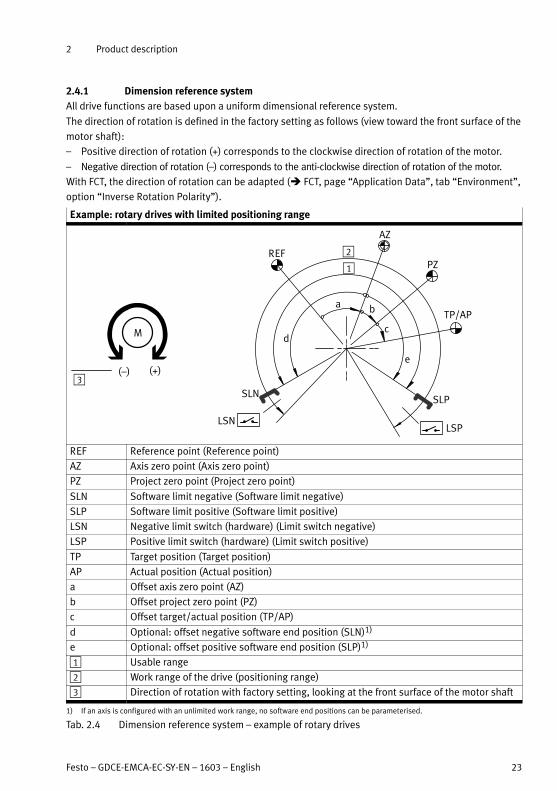
2.4.1 Dimension reference system
All drive functions are based upon a uniform dimensional reference system.
The direction of rotation is defined in the factory setting as follows (view toward the front surface of the
motor shaft):
– Positive direction of rotation (+) corresponds to the clockwise direction of rotation of the motor.
– Negative direction of rotation (–) corresponds to the anti-clockwise direction of rotation of the motor.
With FCT, the direction of rotation can be adapted ( FCT, page “Application Data”, tab “Environment”,
option “Inverse Rotation Polarity”).
Example: rotary drives with limited positioning range
REF
AZ
a b
e
PZ
d
1
2
M
(+)(–)
c
TP/AP
SLPSLN
LSNLSP
3
REF Reference point (Reference point)
AZ Axis zero point (Axis zero point)
PZ Project zero point (Project zero point)
SLN Software limit negative (Software limit negative)
SLP Software limit positive (Software limit positive)
LSN Negative limit switch (hardware) (Limit switch negative)
LSP Positive limit switch (hardware) (Limit switch positive)
TP Target position (Target position)
AP Actual position (Actual position)
a Offset axis zero point (AZ)
b Offset project zero point (PZ)
c Offset target/actual position (TP/AP)
d Optional: offset negative software end position (SLN)1)
e Optional: offset positive software end position (SLP)1)
1 Usable range
2 Work range of the drive (positioning range)
3 Direction of rotation with factory setting, looking at the front surface of the motor shaft
1) If an axis is configured with an unlimited work range, no software end positions can be parameterised.
Tab. 2.4 Dimension reference system – example of rotary drives
2 Product description
24 Festo – GDCE-EMCA-EC-SY-EN – 1603 – English
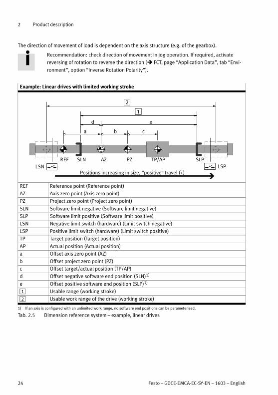
The direction of movement of load is dependent on the axis structure (e.g. of the gearbox).
Recommendation: check direction of movement in jog operation. If required, activate
reversing of rotation to reverse the direction ( FCT, page “Application Data”, tab “Envi
ronment”, option “Inverse Rotation Polarity”).
Example: Linear drives with limited working stroke
1
REF AZ
a b c
PZ
d e
TP/AP SLPSLN
2
Positions increasing in size, “positive” travel (+)LSN LSP
REF Reference point (Reference point)
AZ Axis zero point (Axis zero point)
PZ Project zero point (Project zero point)
SLN Software limit negative (Software limit negative)
SLP Software limit positive (Software limit positive)
LSN Negative limit switch (hardware) (Limit switch negative)
LSP Positive limit switch (hardware) (Limit switch positive)
TP Target position (Target position)
AP Actual position (Actual position)
a Offset axis zero point (AZ)
b Offset project zero point (PZ)
c Offset target/actual position (TP/AP)
d Offset negative software end position (SLN)1)
e Offset positive software end position (SLP)1)
1 Usable range (working stroke)
2 Usable work range of the drive (working stroke)
1) If an axis is configured with an unlimited work range, no software end positions can be parameterised.
Tab. 2.5 Dimension reference system – example, linear drives

2 Product description
Festo – GDCE-EMCA-EC-SY-EN – 1603 – English 25
Calculation rules for the dimension reference system
Point of reference Calculation rule
Axis zero point AZ = REF a
Project zero point PZ = AZ b = REF a + b
Negative software end position SLN = AZ d = REF a d
Positive software end position SLP = AZ e = REF a e
Target position/actual position TP/AP = PZ c = AZ b c = REF a b + c
Tab. 2.6 Calculation rules for the dimension reference system
Limit switch LSN/LSP (hardware)
Limit switches limit the absolute usable range of the drive. The switching function “N/C contact” or
“N/O contact” can be parameterised dependent on the limit switch type. The reaction of the device to
limit switch signals can be parameterised with the FCT error management. A distinction is made thereby
between the following cases:
– Limit switch positive active (message 07h)
– Limit switch negative active (message 08h)
For additional information on determining the behaviour FCT error management.
The drive is blocked in the positioning direction of the active limit switch. As soon as the limit switch is
active, travel is possible only in the reverse direction after acknowledgment of the error.
Software end position SLN/SLP
Delineation of an area of use within the operating area takes place through parameterisation of soft
ware end positions. The position is specified relative to the axis zero point AZ.
Note
Movement to fixed stops is not permitted during operation.
Limit operating area through software end positions.
Establish software end positions sufficiently far away from the mechanical stops.
The controller checks before the start whether the target position of the command record lies between
the software end positions SLN/SLP. If a target position lies outside this range, the position set is not
executed and the parameterised error response is triggered.
Before the software end position is reached, the drive is braked according to the error response, so
that the software end position is not passed. After stopping, the positioning direction is blocked.
If the controller is not released, the software end positions are not monitored. If the drive is moved
manually behind a software end position, after release of the controller, only travel toward the usable
range is possible. If the target of the next positioning motion is even further outside the usable range,
a corresponding error is reported. If the target of the next positioning motion lies within the usable
range, travel can take place into the usable range without error.
Parameterisation of the following error messages can influence behaviour if the software end positions
are violated: 11h, 12h, 13h, 14h, 29h, 2Ah.
For additional information on determining the behaviour FCT error management.
2 Product description
26 Festo – GDCE-EMCA-EC-SY-EN – 1603 – English
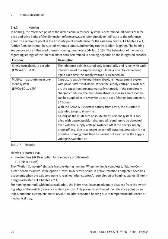
2.4.2 Homing
In homing, the reference point of the dimensional reference system is determined. All points of refer
ence and drive limits of the dimension reference system refer directly or indirectly to the reference
point. The reference point is the absolute point of reference for the axis zero point ( Chapter 2.4.1).
A drive function cannot be started without a successful homing run (exception: jogging). The homing
sequence can be influenced through homing parameters ( Tab. 2.15). The behaviour of the device
regarding storage of the internal offset data determined in homing depends on the integrated encoder.
Encoder Description
Single-turn absolute encoder
(EMCA-EC-...-1TE)
The reference point is stored only temporarily and is lost with each
interruption of the supply voltage. Homing must be carried out
again each time the supply voltage is switched on.
Multi-turn absolute measure
ment system
(EMCA-EC-...-1TM)
Capacitors supply the multi-turn absolute measurement system
with power after shut-down. When the supply voltage is switched
on, the capacitors are automatically charged. In the completely
charged condition, the multi-turn absolute measurement system
can be supplied in this way for up to 7 days (charge duration, min.
24 hours).
With the EADA-A-9 external battery from Festo, the duration is
extended to up to 6 months.
As long as the multi-turn absolute measurement system is sup
plied with power, position changes will continue to be detected
even with the supply voltage switched off. If the energy supply
drops off, e.g. due to a longer switch-off duration, detection is not
possible. Homing must then be carried out again after the supply
voltage is switched on.
Tab. 2.7 Encoder
Homing is started via:
– the fieldbus ( Description for the device profile used)
– FCT ( FCT Help)
The “Motion Complete” signal is inactive during homing. When homing is completed, “Motion Com
plete” becomes active. If the option “Travel to axis zero point” is active, “Motion Complete” becomes
active only when the axis zero point is reached. After successful completion of homing, standstill monit
oring is activated ( Chapter 2.7.1).
For homing methods with index evaluation, the index must have an adequate distance from the switch
ing edge of the switch (reference or limit switch). This prevents shifting of the reference point by an
index, and thus a complete motor revolution, after repeated homing due to temperature influences or
mechanical play.

2 Product description
Festo – GDCE-EMCA-EC-SY-EN – 1603 – English 27
Recommendation: FCT displays the distance between the switching edge and index
( FCT, online tab “Homing”).
Align the reference switch in the middle between two index signals.
1 Position of the
switching edge
2 Index
3 Distance from
the index
REF
1
2
3
Fig. 2.5 Alignment of the reference switch during index evaluation – example
Homing methods
The homing method defines how the homing point REF is ascertained. Homing methods with index
evaluation offer a higher repetition accuracy in determining the reference point.
Destination CiA 4021) Brief description
Current position DDh -35 Current position becomes the reference point.
Stop The mechanical stop is sought during homing. If the
stop is detected in accordance with the parameterisa
tion (force limit/torque limit, damping time), the posi
tion becomes the homing point.
– Positive direction EEh -18
– Negative direction EFh -17
Limit switch without index During homing, the position of the limit switch is
searched for. When successful, the position of the
switch becomes the homing point.
– Positive direction 12h 18
– Negative direction 11h 17
Limit switch with index During homing, the position of the limit switch is
searched for. When successful, the drive travels back
to the next index of the encoder. This position be
comes the reference point.
– Positive direction 02h 02
– Negative direction 01h 01
Reference switch without index During homing, the position of the reference switch is
searched for. When successful, the position of the
switch becomes the homing point.
– Positive direction 17h 23
– Negative direction 1Bh 27
Reference switch with index During homing, the position of the reference switch is
searched for. When successful, the drive travels back
to the next index of the encoder. This position be
comes the reference point.
– Positive direction 07h 7
– Negative direction 0Bh 11
1) The homing methods are based on the CANopen device profile CiA 402 V 3.0.
Tab. 2.8 Homing methods – overview

2 Product description
28 Festo – GDCE-EMCA-EC-SY-EN – 1603 – English
Current position (transfer as reference point)
1. The current position is taken as the homing point. A travel movement takes place only if the option
“travel to the axis zero point” is active.
2. Optional: travel to the axis zero point ( Tab. 2.16).
Transfer current position (method DDh; -35)
Tab. 2.9 Homing method – current position
Homing to the stop
The stop is detected by a motor shutdown in combination with a sharp rise in the motor current and
expiration of the damping time. After that, the stop position must be abandoned through travel to the
axis zero point.
If the drive system does not have a stop (axis of rotation), homing will never be completed. The drive
then travels continuously at the parameterised search speed.
Note
If the controller continuously controls against a stop, the temperature rises sharply and
the controller shuts itself down.
Set parameters for stop detection (force limit, damping time)
Option of enabling “Position from homing point to the axis zero point”.
The axis zero point must be set in such a way that the axis does not run against the
stop/limit position damping in operation, even with overswinging (e.g. ≥ 3 mm).
A suitable value is preset at the factory. Do not change the presetting, if possible.
Pay attention to the direction specification (algebraic sign) of the offset (away from
the stop).
Note
Material damage due to shifted dimension reference system.
In the event of greatly reduced dynamic values (low parameterised maximum motor
current) combined with high travelling resistance (e.g. due to frictional grip), there is
a danger that the drive will come to a standstill and the controller will recognise a stop
incorrectly.
Note
When homing to stop:
Protect delicate stops by reducing the search speed.

2 Product description
Festo – GDCE-EMCA-EC-SY-EN – 1603 – English 29
Homing to the stop
1. Search for the stop with search speed in the parameterised direction:1)
– Stop missing (rotary axis): The drive continues infinitely.
– Stop not recognised: EMCA regulates against the stop, shuts down if temperature rises above
its defined limit.
2. Stop detected: position is adopted as the homing point.
3. Travel to the axis zero point2)
Direction: positive (method EEh; -18) Direction: negative (method EFh; -17)
1) Limit switches are ignored during travel to the stop.
2) In this homing method, the option “Travel to axis zero point” is always active ( Tab. 2.16).
Tab. 2.10 Homing method – homing to stop
Homing to limit switch
Homing to limit switch without index
1. If the limit switch is not actuated: search for the limit switch with search speed in the paramet
erised direction. If the switch is detected, the next step takes place ( 2.).
If the limit switch is already actuated, the next step takes place ( 2.).
If the limit switch is not found:
– For rotary drives without stop: The drive continues infinitely.
– For drives with stop: Travel to stop, stop detection, termination of homing with malfunction
message 0x22 (FCT code).
2. Limit switch detected: Search for reference point at creep speed opposite to the parameterised
direction until the limit switch is again unactuated. This position is taken as the reference point.
3. Optional: travel to the axis zero point ( Tab. 2.16).
Direction: positive (method 12h; 18) Direction: negative (method 11h; 17)
Positive limit switch Negative limit switch
Tab. 2.11 Homing method – Homing to limit switch without index
2 Product description
30 Festo – GDCE-EMCA-EC-SY-EN – 1603 – English
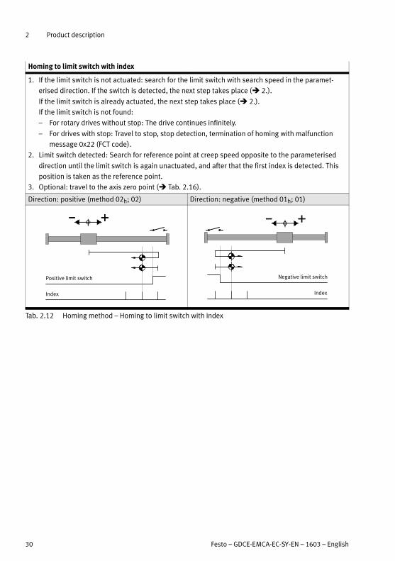
Homing to limit switch with index
1. If the limit switch is not actuated: search for the limit switch with search speed in the paramet
erised direction. If the switch is detected, the next step takes place ( 2.).
If the limit switch is already actuated, the next step takes place ( 2.).
If the limit switch is not found:
– For rotary drives without stop: The drive continues infinitely.
– For drives with stop: Travel to stop, stop detection, termination of homing with malfunction
message 0x22 (FCT code).
2. Limit switch detected: Search for reference point at creep speed opposite to the parameterised
direction until the limit switch is again unactuated, and after that the first index is detected. This
position is taken as the reference point.
3. Optional: travel to the axis zero point ( Tab. 2.16).
Direction: positive (method 02h; 02) Direction: negative (method 01h; 01)
Positive limit switch
Index
Negative limit switch
Index
Tab. 2.12 Homing method – Homing to limit switch with index

2 Product description
Festo – GDCE-EMCA-EC-SY-EN – 1603 – English 31
Homing to reference switch
Homing to reference switch without index
1. If the reference switch is not actuated: search for the reference switch with search speed in the
parameterised direction. If the switch is detected, the next step takes place ( 2.).
If the reference switch is already actuated, the next step takes place ( 2.).
If the reference switch is not found:
– For rotary drives without stop: The drive continues infinitely.
– For drives with stop: Travel to stop, stop detection, search in reverse direction
– Switch in opposite direction not found: termination with error message 0x22 (FCT code)
2. Reference switch detected: Search for reference point at creep speed opposite to the paramet
erised direction until the reference switch is again unactuated. This position is taken as the refer
ence point.
3. Optional: travel to the axis zero point ( Tab. 2.16).
Direction: positive (method 17h; 23) Direction: negative (method 1Bh; 27)
Reference switch Reference switch
Tab. 2.13 Homing method – homing to reference switch without index

2 Product description
32 Festo – GDCE-EMCA-EC-SY-EN – 1603 – English
Homing to reference switch with index
1. If the reference switch is not actuated: search for the reference switch with search speed in the
parameterised direction. If the switch is detected, the next step takes place ( 2.).
If the reference switch is already actuated, the next step takes place ( 2.).
If the reference switch is not found:
– For rotary drives without stop: The drive continues infinitely.
– For drives with stop: Travel to stop, stop detection, search in reverse direction
– Switch in opposite direction not found: termination with error message 0x22 (FCT code)
2. Reference switch detected: Search for reference point at creep speed opposite to the paramet
erised direction until the reference switch is again unactuated, and after that the first index is
detected. This position is taken as the reference point.
3. Optional: travel to the axis zero point ( Tab. 2.16).
Direction: positive (method 07h; 7) Direction: negative (method 0Bh; 11)
Reference switch
Index
Reference switch
Index
Tab. 2.14 Homing method – homing to reference switch with index

2 Product description
Festo – GDCE-EMCA-EC-SY-EN – 1603 – English 33
Homing parameters
The following parameters are effective when executing homing, depending on the homing method:
Homing parameter Description
Target (Target) Homing method ( Tab. 2.8)
Direction (Direction)
Search speed
(Search Velocity)
Speed of searching travel to the defined target
Creep speed
(Crawling Velocity)
Speed for crawling travel to the reference point (only for methods
with reference or limit switch)
Travel speed
(Drive Velocity)
Travel speed for the option “Drive to axis zero point”
Acceleration
(Acceleration)
Acceleration and deceleration for all phases of reference travel
Axis zero point
(Axis Zero Point)
The distance of the axis zero point from the reference point in
positive or negative direction (offset)
Force limit (linear axis) or
torque limit
(Force Limit/Torque Limit)
Percentage specification of force (with reference to the paramet
erised base value of the motor current) at which impact detection
is effective
Damping time
(Message Delay)
Time period in which the force must lie above the force limit so
that a stop is considered detected
Tab. 2.15 Homing parameters
Select low search/crawl speed to enable the target points to be identified as accur
ately as possible.
Set deceleration high enough to prevent the targets from being overrun too far during
the search run.
Use the default settings, if possible.
Homing option Function
Travel to axis zero point after homing
– Active1) When homing is concluded, the drive automatically travels to the
axis zero point.
– Inactive The drive remains position-controlled at the reference point.
1) With the homing method “Homing to stop”, this option is always active.
Tab. 2.16 Homing option

2 Product description
34 Festo – GDCE-EMCA-EC-SY-EN – 1603 – English
2.4.3 Jog operation (only via FHPP or with FCT)
In jog operation, the drive can moved to any position. The drive is moved during jogging until the jog
ging signal is present. For referenced drives, the limits are determined by the software end positions.
For unreferenced drives, limit switches or stops represent the limits for jogging.
Jogging supports the following functions:
– Approaching teach positions (e.g. during commissioning)
– Free-running of drive (e.g. after a system malfunction)
– Manual positioning as a normal operating mode (manually operated feed)
Jogging can be influenced with the following parameters:
Parameter Description
Crawling speed
(Crawling velocity)
Setpoint value for the speed when starting a jog movement
Duration of crawling
(Slow moving time)
Setpoint value for the duration of crawling
Max. speed
(Maximum velocity)
Maximum speed at the end of slow-moving time
Acceleration
(Acceleration)
Setpoint value for acceleration phases and the deceleration phase
Max. permitted following error
(Maximum following error)
Value for the permissible following error for jog movement
Damping time (Message delay) A fault is generated if the following error is present for longer than
the time parameterised here.
Tab. 2.17 Parameters for jog operation
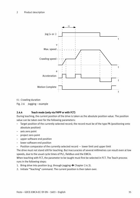
Jogging transpires as follows ( Fig. 2.6):
– Upon detection of the jog signal (Jog+ or Jog-), the drive travels at crawling speed in the correspond
ing direction.
– If the jog signal continues after the end of the slow-moving time, the drive accelerates to jog speed.
Bigger strokes can thus be completed more rapidly.
– With a trailing edge of the jog signal, the drive is braked to a standstill.
2 Product description
Festo – GDCE-EMCA-EC-SY-EN – 1603 – English 35
t
v
Crawling speed
Max. speed
t
t
Jog (+ or -)
t1
Acceleration
Motion Complete
t
a
t1 : Crawling duration
Fig. 2.6 Jogging – example
2.4.4 Teach mode (only via FHPP or with FCT)
During teaching, the current position of the drive is taken as the absolute position value. The position
value can be taken over for the following parameters:
– Target position of the currently selected record; the record must be of the type PA (positioning onto
absolute position)
– axis zero point
– project zero point
– upper software end position
– lower software end position
– Position comparator of the currently selected record — lower limit and upper limit
The drive must not stand still for teaching. But inaccuracies of several millimetres can result even at low
speeds, due to the usual cycle times of PLC, fieldbus and the EMCA.
When teaching with FCT, the parameter to be taught must first be selected in FCT. The Teach process
runs in the following steps:
1. Bring drive into position (e.g. through jogging Chapter 2.4.3).
2. Initiate “Teaching” command. The current position is then taken over.

2 Product description
36 Festo – GDCE-EMCA-EC-SY-EN – 1603 – English
For information on teaching with FCT Hlug-in help for the FCT.
Information on teaching via FHPP FHPP device profile description, GDCE-EMCA-EC-C-HP-....
Note
When teaching with FCT, observe the notes in the plug-in help.
2.4.5 Positioning mode
The positioning mode makes it possible to reach a target position via a defined path.
To enable this, the drive calculates a time-optimised path curve, in which the following parameters are
considered, among others:
– performance of the electric drive
– limits for protection of the mechanical system
– requirements from the application that were parameterised by the user (e.g. smoothing during
transport of liquid media)
The path course of a positioning order is largely influenced by the following parameters:
Parameter Description
Position (Position) Destination specification (specification of a route or absolute
position Tab. 2.19)
Speed (Velocity) Setpoint value for speed
Acceleration (Acceleration) Setpoint value for acceleration
Deceleration (Deceleration) Setpoint value for deceleration1)
Jerk acceleration
(Jerk for acceleration)
Maximum value for the jerk during the acceleration phase2)
Jerk deceleration (Jerk for dece
leration)
Maximum value for the jerk during the deceleration phase1)2)
1) Separately adjustable in FCT if the asymmetric ramp generator has been activated
2) The jerk in [m/s³] is the first derivative of the acceleration. Lower values cause gentler starting and braking action.
Tab. 2.18 Parameters for influencing the movement course
A theoretical progression is calculated from the parameters before a positioning order is executed. The
calculated path course remains unchanged until the end of the positioning order. While a positioning
order is being carried out, the deviation between the setpoint position based on the previously calcu
lated path course and the actual position is calculated and monitored ( Chapter 2.7.1, following error
monitoring).
Destination specification Description
Absolute Position, referenced to the axis zero point
Relative to the setpoint position Distance referenced to the last setpoint position
Relative to the actual position Distance referenced to the current position (actual position)
Tab. 2.19 Variants of the destination specification in positioning mode
2 Product description
Festo – GDCE-EMCA-EC-SY-EN – 1603 – English 37
t
t
Acceleration
Deceleration
Speed
t
s
Target position
EndStarta
v
Motion Complete
t
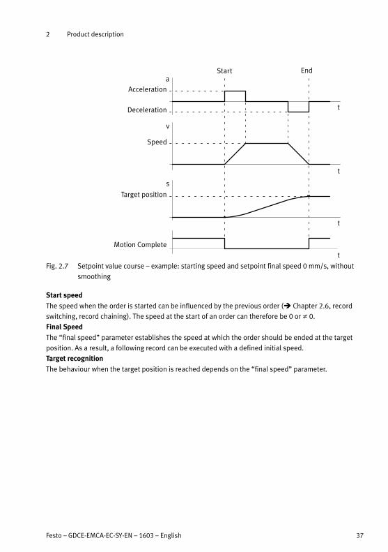
Fig. 2.7 Setpoint value course – example: starting speed and setpoint final speed 0 mm/s, without
smoothing
Start speed
The speed when the order is started can be influenced by the previous order ( Chapter 2.6, record
switching, record chaining). The speed at the start of an order can therefore be 0 or ≠ 0.
Final Speed
The “final speed” parameter establishes the speed at which the order should be ended at the target
position. As a result, a following record can be executed with a defined initial speed.
Target recognition
The behaviour when the target position is reached depends on the “final speed” parameter.

2 Product description
38 Festo – GDCE-EMCA-EC-SY-EN – 1603 – English
Final speed
parameter
Motion Complete (Target recognition) Behaviour after target recognition
= 0 The positioning order is considered
ended when the actual position is loc
ated in the target window for the es
tablished damping time.
As long as no other drive function is
executed, the drive will stop at the tar
get position in a position-controlled
manner.
Standstill monitoring is activated
( Chapter 2.7.1).
≠ 0 The positioning order is considered
complete when the target position has
been reached or passed.
The drive continues with the final
speed of the positioning order, without
monitoring of the deviation.
The force is limited to the maximum
value defined in the position record.
Tab. 2.20 Target recognition in positioning mode
Additional parameters for order processing
The usable parameters depend on the operating mode and the device profile used. In
formation on the available parameters for the device profile used Description for the
device profile used.
Parameter Description
Start Condition
(Start Condition)
Reaction to a start signal if the current order has not been ended
yet (record switching Tab. 2.33)
Extra Load
(Extra Load)
Payload that is transported in addition to the base load
Torque Feed Forward
(Torque Feed Forward)
Adjustment of the motor setpoint current by the set percentage
(for greater dynamic response with large loads)
The value must be determined experimentally.
Force/Torque Limitation (Force
Limit/ Torque Limit)
Limitation of the force (linear drive) or the torque (rotational drive)
that can be generated during execution of the order
Max. Following Error
(Max. Following Error)
Determination when the “following error” message should be
output ( Fig. 2.16)
Position Comparator
(Position Comparator)
Monitoring of a position window ( Chapter 2.7.2)
Speed Comparator (Velocity
Comparator)
Monitoring of a velocity window ( Chapter 2.7.2)
Time Comparator
(Time Comparator)
Monitoring of a time window that starts with the beginning of the
order execution ( Chapter 2.7.2)
Force/Torque Comparator
(Force Comparator/ Torque
Comparator)
Monitoring of a force or torque window ( Chapter 2.7.2)

2 Product description
Festo – GDCE-EMCA-EC-SY-EN – 1603 – English 39
Parameter Description
Condition
(Condition)
Step enabling condition that must be fulfilled before the sub
sequent order is started ( Chapter 2.6.2)
Start delay
(Start Delay)
Waiting time that expires before the record is started from a record
chaining ( Chapter 2.6.2)
MC visible
(MC visible)
Signal “Motion Complete” between the individual records of a
record chaining; the signal length is influenced through the “Re
cord Delay” parameter ( Chapter 2.6.2).
Final Speed
(Final Velocity)
The final speed at which the order should be ended at the target
position; the drive can thus start a subsequent order at this speed
without coming to a standstill.
Following Set
(Following Set)
Record number of the next record ( Chapter 2.6.2)
Tab. 2.21 Additional parameters for order processing – example, record and direct mode
2.4.6 Speed mode
The speed mode permits regulation of the speed (linear drive) or rotational speed (rotary drive).
The path course is largely influenced by the following parameters:
Parameter Description
Speed (Velocity) Target specification for speed
Acceleration (Acceleration) Setpoint value for acceleration
Deceleration (Deceleration) Setpoint value for deceleration1)
Jerk Acceleration (Jerk for Acce
leration)
Maximum value for the jerk during the acceleration phase
Jerk Deceleration (Jerk for Dece
leration)
Maximum value for the jerk during the deceleration phase1)
Force Limiter (Force Limit) Limits the maximum force
1) Separately adjustable in FCT if the asymmetric ramp generator has been activated
Tab. 2.22 Parameters for influencing the movement course
As in positioning mode, a theoretical path course is calculated from the parameters for the speed mode
prior to execution ( Chapter 2.4.5). This path course remains unchanged until the end of the order.
While the order is being carried out, the deviation between the setpoint speed based on the initially
calculated path course and the actual speed is calculated and monitored ( Chapter 2.7.1, following
error monitoring).
Start speed
The speed when the order is started can be influenced by the previous order ( Chapter 2.6, record
switching, record chaining). The speed at the start of an order can be 0 or ≠ 0.

2 Product description
40 Festo – GDCE-EMCA-EC-SY-EN – 1603 – English
Target recognition
Motion Complete
(Target recognition)
Behaviour after target recognition
An order in speed mode is con
sidered finished when the actu
al speed is inside the target
speed window for the duration
of the parameterised damping
time.
As long as no other drive function is executed, the drive will contin
ue to be controlled by the setpoint speed.
Monitoring of the speed deviation remains active until a new drive
function is executed.
The force is limited to the maximum value specified in the speed
record. The stroke limit remains active.
Tab. 2.23 Target recognition in velocity mode
Variants
The following variants of speed regulation are available:
– speed regulation without stroke limit
– speed regulation with stroke limit
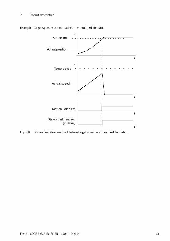
Parameter Description
Stroke limit
(Stroke Limit)
Limits the distance that may be travelled during execution of the
order.
When the stroke limit is reached, the device reacts as follows:
– The drive is braked down to a stop using the parameterised
Quick-Stop deceleration function.
– Although the target speed has not yet been reached, the “Mo
tion Complete” signal is set ( Fig. 2.8 and Fig. 2.10).
If no other drive function is to be executed, the drive will stop in
a position-controlled manner. Standstill monitoring is activated.
Tab. 2.24 Stroke limit parameter
2 Product description
Festo – GDCE-EMCA-EC-SY-EN – 1603 – English 41
Example: Target speed was not reached – without jerk limitation
Motion Complete
Stroke limit reached(internal)
t
t
t
t
Target speed
sStroke limit
Actual position
Actual speed
v
Fig. 2.8 Stroke limitation reached before target speed – without jerk limitation
2 Product description
42 Festo – GDCE-EMCA-EC-SY-EN – 1603 – English
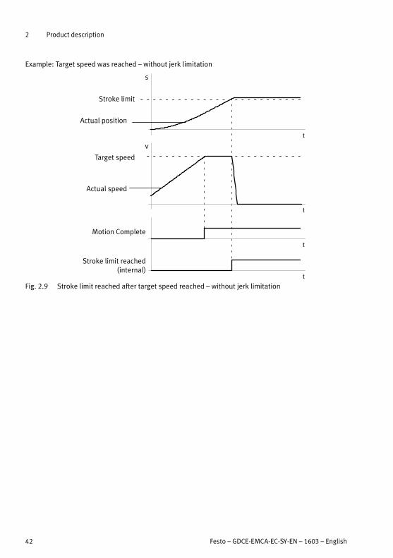
Example: Target speed was reached – without jerk limitation
Motion Complete
Stroke limit reached(internal)
t
t
s
Target speed
Stroke limit
Actual position
Actual speed
v
t
t
Fig. 2.9 Stroke limit reached after target speed reached – without jerk limitation

2 Product description
Festo – GDCE-EMCA-EC-SY-EN – 1603 – English 43
Example: Target speed was reached – with jerk limitation
Motion Complete
Stroke limit reached(internal)
t
t
s
Target speed
Stroke limit
Actual position
Actual speed
v
t
t
Fig. 2.10 Stroke limit reached after target speed reached – with jerk limitation
Additional parameters for order processing Tab. 2.21.
The usable parameters depend on the operating mode and the device profile used.
Information on the available parameters for the device profile used Description for the
device profile used.
2.4.7 Force/torque mode
The force/torque mode permits force control. The motor force is controlled indirectly through regula
tion of the motor current. The generated force is theoretically calculated over the measured current
(Force is proportional to the motor current). Depending on the mechanical system of the drive, this
results in a torque or linear force.
The target specification is based on a percentage of the parameterised base value of the motor current.
The actual force at the axis must be checked at commissioning using external measuring equipment.
Deviations between the actual and the desired force can be reduced by adjusting the parameterisation.

2 Product description
44 Festo – GDCE-EMCA-EC-SY-EN – 1603 – English
The path course of an order in force/torque mode is largely influenced by the following parameters:
Parameter Description
Force (Force) Target specification for force (in % of the parameterised base value
of the motor current)
Speed (Velocity) Setpoint value for speed
Acceleration (Acceleration) Setpoint value for acceleration
Deceleration (Deceleration) Setpoint value for deceleration1)
1) Separately adjustable in FCT if the asymmetric ramp generator has been activated
Tab. 2.25 Parameters for influencing the movement course in force/torque mode
Start force
The actual speed at the start of the order can be influenced by the previous order. The actual force at
the start of the order can be 0 or ≠ 0.
Target recognition
Motion Complete
(Target recognition)
Behaviour after target recognition
An order in the force/torque
mode is considered finished
when the calculated actual
force is located in the target
window for the established
damping time.
As long as no other drive function is executed, the drive will contin
ue to be controlled by the setpoint force.
The speed remains limited to the maximum value specified in
the order.
The stroke limit remains active.
Tab. 2.26 Target recognition in force/torque mode
Variants of the force/torque mode
The following variants of the force/torque mode are available:
– force/torque mode without stroke limit
– force/torque mode with stroke limit.
Parameter Description
Stroke limit
(Stroke Limit)
Limits the distance that may be travelled during execution of the
order.
When the stroke limit is reached, the device reacts as follows:
– The “Stroke limit reached” signal is set.
– The drive is braked down to a stop using the parameterised
Quick-Stop deceleration function.
If no other drive function is to be executed, the drive will stop at
the stroke limit in a position-controlled manner. Standstill monitor
ing is activated and the “Motion Complete” signal is set.
Tab. 2.27 Stroke limit parameter

2 Product description
Festo – GDCE-EMCA-EC-SY-EN – 1603 – English 45
Additional parameters for order processing
Additional parameters for order processing Tab. 2.21.
The usable parameters depend on the operating mode and the device profile used. In
formation on the available parameters for the device profile used Description for the
device profile used.
2.4.8 Stop (halt), Quick-Stop
Stop (halt)
In a stop, the drive is braked with the parameterised deceleration of the active position set until stand
still. The drive stops in a position-controlled manner. Standstill monitoring is activated. A stop (halt) can
be triggered via:
– fieldbus ( Device profile description)
The reaction to the Stop signal (halt) depends on the current control mode (positioning mode, speed
mode or force/torque mode).
Stop (halt) in ... Description
Positioning mode In positioning mode, the Stop signal (halt) first results in an intermediate stop.
Intermediate stop means:
– The “Motion Complete” signal is not set.
– The order is interrupted (considered not finished). The order can be contin
ued ( Description of the device profile).
The positioning order can be interrupted through the “Delete remaining path”
signal. The intermediate stop then becomes a stop ( Description of the device
profile).
Stop means:
– The “Motion Complete” signal is set.
– The order is discontinued and considered completed.
Speed mode or
force/torque
mode
In speed or force/torque mode, the Stop signal (halt) results in a stop.
Stop means:
– The “Motion Complete” signal is set.
– The order is discontinued and considered completed.
Tab. 2.28 Stop drive
Quick-Stop (Fast stop)
In a Quick-Stop, the drive is braked down to a stop using the parameterised Quick-Stop deceleration
function. Quick-Stop is triggered in the following cases:
– Withdrawal of controller enable. After completion of the Quick-Stop deceleration, the drive is
blocked (output stage switched off ). The drive is uncontrolled.
– For errors for which the “Quick-Stop deceleration” error reaction has been parameterised ( Error
management)
– Achievement of the stroke limit (speed mode, force/torque mode)
– Quick-Stop via fieldbus Device profile description
2 Product description
46 Festo – GDCE-EMCA-EC-SY-EN – 1603 – English
2.4.9 Holding brake (only EMCA-EC-...-...-B)
The EMCA-EC-...-B has an EC motor with holding brake. The holding brake is intended to hold the motor
position/drive position in a state of rest and is only used at a standstill. In principle, the holding brake
can also be used for dynamic brake procedures. This results in higher wear. Frequent dynamic brake
procedures (e.g. 1 x per day) can result in the holding brake wearing out prematurely.
Note
Using the holding brake
Improper use of the holding brake causes increased wear of the brake disc, which res
ults in a reduction of the holding torque. The holding function is therefore no longer
guaranteed.
The holding brake cannot be replaced or repaired. In case of defect, the device must be
completely replaced.
Build-up of the holding torque
The full holding torque of the brake is only built up through a small relative movement between the
friction surface of the holding brake and the anchor plate. If there is an external torque load on the
motor shaft, this results in a small rotation. This effect can be eliminated through repeated operation at
low rotational speed.
Automatic control of the holding brake
The EMCA-EC-...-B controls the holding brake automatically. The holding brake is released when the
controller is enabled. The holding brake is activated when the controller is blocked.
Manual release of the holding brake
When the controller is blocked, the holding brake can be released as follows:
– via the FCT ( Jnline help)
– through the “Brake” signal via the control interface ( Description of the used device profile)
Parameterisation
The inertia of the holding brake means that it takes a certain length of time to release and activate it.
The behaviour of the device is adapted to the inertia of the holding brake by the following parameters
( FCT, “Motor” page, “Brake control” tab).

2 Product description
Festo – GDCE-EMCA-EC-SY-EN – 1603 – English 47
Parameter Description
Switch-on delay Delay before execution of the next order:
1. When the controller is enabled, the holding brake is first released.
The position controller takes over the control (actual position = setpoint
position).
2. No orders are processed until the switch-on delay has elapsed, so that the
holding brake can release completely.
3. After the switch-on delay has elapsed, orders are accepted. The holding
brake should then be completely released.
Switch-off delay Delay prior to shut-down of the position controller:
1. Removal of the controller enable triggers a quick-stop. If the setpoint speed
is 0, the signal for closing the holding brake is given.
2. The drive is maintained in its current position until the end of the switch-off
delay.
3. The position controller is switched off after expiration of the switch-off delay.
The holding brake should then be completely closed.
Tab. 2.29 Parameterisation of the holding brake
The parameters for control of the holding brake are preset at the factory to appropriate values.
Recommendation: Do not change the factory setting, if possible.
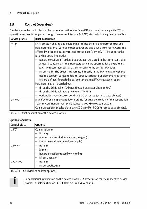
2 Product description
48 Festo – GDCE-EMCA-EC-SY-EN – 1603 – English
2.5 Control (overview)
The device can be controlled via the parameterisation interface (X1) for commissioning with FCT. In
operation, control takes place through the control interface (X2, X3) via the following device profiles.
Device profile Brief description
FHPP FHPP (Festo Handling and Positioning Profile) permits a uniform control and
parameterisation of various motor controllers and drives from Festo. Control is
effected via the cyclical control and status data (8 bytes). FHPP supports the
following operating modes:
– Record selection: 64 orders (records) can be stored in the motor controller.
A record contains all the parameters which are specified for a positioning
job. The record numbers are transferred into the cyclical I/O data.
– Direct mode: The order is transmitted directly in the I/O telegram with the
desired setpoint values (position, speed, current). Supplementary paramet
ers are defined through the parameter channel FPC (e.g. acceleration).
Parameterisation is carried out:
– through additional 8 I/O bytes (Festo Parameter Channel FPC)
– through additional max. 3 I/O bytes (FHPP+)
– optionally through corresponding SDO accesses (service data objects)
CiA 402 Manufacturer-independent device profile for drive controllers of the association
“CAN in Automation” (CiA Draft Standard 402 www.can-cia.de).
Communication can take place over SDOs and/or PDOs (process data objects).
Tab. 2.30 Brief description of the device profiles
Options for control
Control via ... Options
... FCT Commissioning:
– Homing
– Manual process (individual step, jogging)
– Record selection (manual, test cycle)
... FHPP – Homing
– Jogging
– Record selection (record 0 = homing)
– Direct operation
... CiA 402 – Homing
– Direct application
Tab. 2.31 Overview of control options
For additional information on the device profiles Description for the respective device
profile. For information on FCT Help on the EMCA plug-in.

2 Product description
Festo – GDCE-EMCA-EC-SY-EN – 1603 – English 49
2.6 Operational principle for record selection
The operational principle for record selection is not supported by the CiA 402 device profile.
In the device, 64 command records can be stored (record 1 to 64). Record 0 is reserved for homing.
Every stored record contains all required parameters for order processing. To execute an order, the
controlling PLC only needs to transfer the record number to the output data. The device then executes
the corresponding record with the next start signal. Besides the parameters for pure order processing,
record selection offers the following options for influencing sequence control:
Options for
sequence control
Parameter Brief description
Record switching – Start condition A start condition can be defined for every stored
record (e.g. with FCT). The start condition specifies
what the reaction should be to a start signal for the
record if the current order has not been ended yet
( Tab. 2.33).
Record sequencing – Condition (step en
abling condition)
– Start delay
– MC visible
– End speed
– Following set
Several records can be linked with one another.
These are executed with a start signal directly one
after the other if the respective conditions for con
tinuation are met ( Tab. 2.34)
Tab. 2.32 Options for sequence control in record selection
2.6.1 Record switching
Record switching enables flexible switching between records. For each record saved, it is possible to
define how the drive should behave if this record is started while, at the same time, another record is
being executed (start conditions Tab. 2.33).
Start condition Description
Ignore
(Ignore)
While the order is being executed, the start signal is ignored. The current order
is completed. The order can only be started after the MC is active (new start
signal required).
Waiting
(Delay)
The current order is completed. The subsequent order addressed by the last
start signal is only started after the current order has been completed (after the
“Motion Complete” signal).
Interrupt
(Interrupt)
The current order is interrupted immediately and the newly addressed order is
executed directly.
Tab. 2.33 Possible settings for the “Start condition” parameter

2 Product description
50 Festo – GDCE-EMCA-EC-SY-EN – 1603 – English
Example: “Ignore” start condition
The start signal (here for record B) is ignored. The current order (here record A) is completed.
t
t
t
Motion Complete
Start record
Target position record A
A B
Fig. 2.11 “Ignore” start condition
Example: start condition “Waiting”
Initially, the start signals (here for records B and C) are ignored. The current order (here record A) is
completed. Then the last order (here record C) is executed without another start signal.
Target position record A
t
t
t
Motion Complete
Start record A B C
Target position, record C
Fig. 2.12 Start condition “Waiting”

2 Product description
Festo – GDCE-EMCA-EC-SY-EN – 1603 – English 51
Example: start condition “Interrupt”
The current order (here record A) is interrupted immediately and the newly addressed order (here record B)
is executed directly.
Target position record A
t
t
t
Motion Complete
Start record A B
Target position, record B
Fig. 2.13 Start condition “Interrupt”

2 Product description
52 Festo – GDCE-EMCA-EC-SY-EN – 1603 – English
2.6.2 Record sequencing
Record sequencing allows linking of records with each other. In every record, the number of the next
record to be executed can be parameterised. If the step enabling condition is satisfied, the specified
subsequent record is started. A record sequence is executed with the start of a record in the sequence
without any further start command, up to the last record in the sequence. Record sequencing can be
used to implement complex motion sequences, e.g.:
– positioning and clamping in a motion sequence
– travelling a speed profile
– executing a force profile for pressing procedures
The chaining sequence can be influenced by the following parameters:
Parameter Description
Condition (Condition) Indicates when the subsequent record should be started (step enabling
condition)
Start delay
(Start Delay)
Waiting time that expires before the record is started from a record sequen
cing.
MC visible
(MC visible)
Specifies whether the “Motion Complete” message should be output upon
ending of the record. The duration of the signal can be influenced by the
“Start delay” parameter.
Final speed1)
(Final Velocity)
Final speed with which the record should be ended at the target position.
If setpoint final speed is not equal to 0, the damping time for “Motion
Complete” is ineffective.
The final speed must be less than or equal to the parameterised maximum
speed of the order.
Following set
(Following Set)
Number of the record that should be started automatically when the condi
tion is reached.
1) only in positioning mode
Tab. 2.34 Parameters for influencing the movement course
A comparator, for example, can be used as a condition. The following conditions are possible:
Condition (Condition) The following record is started if ...
Motion Complete ... the signal “Motion Complete” becomes active
Position comparator active ... the current position is in the position window for the dura
tion of the damping time
Speed comparator active ... the speed is within the defined speed window for the dura
tion of the damping time
Force comparator active ... the force is in the force/torque window for the duration of
the damping time
Time comparator active ... the length of time for which order processing is in the time
window
Inactive ends record sequencing
Tab. 2.35 “Condition” parameter (Condition)

2 Product description
Festo – GDCE-EMCA-EC-SY-EN – 1603 – English 53
Example: Record linking with final speed ≠ 0 (positioning mode)
The following diagram shows the effect of the parameter “Final speed” on record sequencing. Final and
setpoint speed for record A share the same value. Record B is started without start delay when the
target position of record A is reached without considering the damping time for Motion Complete.
t
Motion Complete
(MC visible)
t
t
Start record sequence
t
Setpoint speed record A
Setpoint speed record B
Position A
Position B
v
s
Fig. 2.14 Following record with final velocity ≠ 0
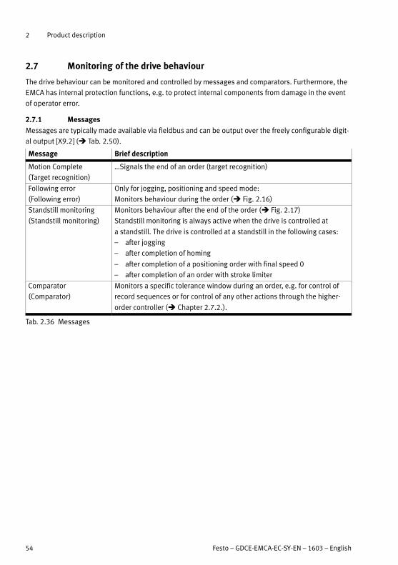
2 Product description
54 Festo – GDCE-EMCA-EC-SY-EN – 1603 – English
2.7 Monitoring of the drive behaviour
The drive behaviour can be monitored and controlled by messages and comparators. Furthermore, the
EMCA has internal protection functions, e.g. to protect internal components from damage in the event
of operator error.
2.7.1 Messages
Messages are typically made available via fieldbus and can be output over the freely configurable digit
al output [X9.2] ( Tab. 2.50).
Message Brief description
Motion Complete
(Target recognition)
Signals the end of an order (target recognition)
Following error
(Following error)
Only for jogging, positioning and speed mode:
Monitors behaviour during the order ( Fig. 2.16)
Standstill monitoring
(Standstill monitoring)
Monitors behaviour after the end of the order ( Fig. 2.17)
Standstill monitoring is always active when the drive is controlled at
a standstill. The drive is controlled at a standstill in the following cases:
– after jogging
– after completion of homing
– after completion of a positioning order with final speed 0
– after completion of an order with stroke limiter
Comparator
(Comparator)
Monitors a specific tolerance window during an order, e.g. for control of
record sequences or for control of any other actions through the higher-
order controller ( Chapter 2.7.2.).
Tab. 2.36 Messages
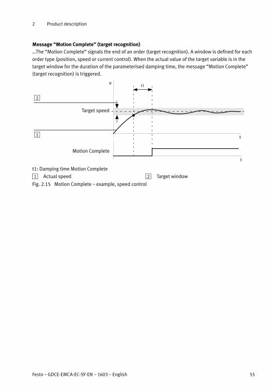
2 Product description
Festo – GDCE-EMCA-EC-SY-EN – 1603 – English 55
Message “Motion Complete” (target recognition)
The “Motion Complete” signals the end of an order (target recognition). A window is defined for each
order type (position, speed or current control). When the actual value of the target variable is in the
target window for the duration of the parameterised damping time, the message “Motion Complete”
(target recognition) is triggered.
Motion Complete
t
t
vt1
1
2
Target speed
t1: Damping time Motion Complete
1 Actual speed 2 Target window
Fig. 2.15 Motion Complete – example, speed control

2 Product description
56 Festo – GDCE-EMCA-EC-SY-EN – 1603 – English
Message “Following error”
With position and speed adjustment, exceeding the maximum permissible following error can be mon
itored. A theoretical progression is calculated from the parameters of an order before it is executed
( Fig. 2.16, 1 ). While carrying out an order, the variance between the calculated setpoint and the
current actual value is monitored. The permitted difference (max. permissible following error) is estab
lished through parameterisation. The message “Following error” is activated after the damping time
has expired if the difference between the setpoint and actual value of the current controlled variable
(path, speed) lies outside the parameterised difference. If the following error has been configured as
a warning, the message is automatically deleted when the actual value is again within the following
error window.
Target position
t1
Start
Following error
Message 2Fh (warning)
1
2
3
s
t
t
t
t1: Damping time for following error
1 Set positioning path
2 Following error window
3 Actual positioning path
Fig. 2.16 Time diagram: message “following error” - example, positioning control, warning
The error management of FCT permits parameterising the reaction to this message (2Fh) ( FCT error
management).
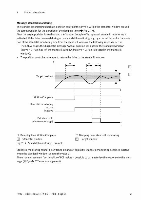
2 Product description
Festo – GDCE-EMCA-EC-SY-EN – 1603 – English 57
Message standstill monitoring
The standstill monitoring checks in position control if the drive is within the standstill window around
the target position for the duration of the damping time ( Fig. 2.17).
After the target position is reached and the “Motion Complete” is reported, standstill monitoring is
activated. If the drive is moved during active standstill monitoring, e.g. by external forces for the dura
tion of the standstill monitoring time from the standstill window, the following response occurs:
– The EMCA issues the diagnostic message “Actual position lies outside the standstill window”
(active = 1: Axis has left the standstill window; inactive = 0: Axis is located in the standstill
window).
– The position controller attempts to return the drive to the standstill window.
Motion Complete
Standstill monitoringactive
inactive
t
t
t
t
s
Exit standstill window (message)
Target position
t1 t2 t2
1
2
t1: Damping time Motion Complete t2: Damping time, standstill monitoring
1 Standstill window 2 Target window
Fig. 2.17 Standstill monitoring - example
Standstill monitoring cannot be switched on and off explicitly. Standstill monitoring becomes inactive
when the standstill window is set to the value 0.
The error management functionality of FCT makes it possible to parameterise the response to this mes
sage (37Fh) ( FCT error management).

2 Product description
58 Festo – GDCE-EMCA-EC-SY-EN – 1603 – English
2.7.2 Comparators
Comparators are not supported by the CiA 402 device profile.
With comparators, certain characteristics of the drive behaviour can be monitored. It is hereby checked
whether a value, e.g. the speed of the drive, lies within a defined range of values. The range of values is
defined by a lower and an upper limit value. For position, speed and force comparators, a damping time
is also established. The message is output if the value remains in the range of values for the duration of
the damping period.
The device does not test whether the limit values make sense. If the lower limit value is
greater than the upper limit value, the comparator message is never active.
Comparators can be used for record selection and, in direct mode, for monitoring. For record selection,
the parameters of the comparators are administered in the position set (e.g. minimum value and max
imum value of the monitoring window). For record sequencing, the comparators can be used as step
enabling conditions ( Chapter 2.6, record sequencing).
For the direct mode, the parameters of the comparators are administered as global parameters for
direct mode (presetting for direct mode).
The configurable digital output ( Tab. 2.48) is usable for the output of comparator messages. If the
monitored value is in the monitoring window, the related comparator message is active. The configur
able digital output is set when it is configured accordingly.
Outside the monitoring window, the comparator message is inactive and the output is reset.
Comparators Brief description
Position comparator1)
(Position comparator)
Monitors a specified position window
Speed comparator1)
(Velocity comparator)
Monitors a specified speed window
Force Comparator1)
(Force comparator)
Monitors a specified force or torque window
Time comparator
(Time comparator)
Monitors a time window that starts with the beginning of record
execution
1) The comparator message is output only if the monitored value remains in the monitoring range for the duration of the set damping
period.
Tab. 2.37 Comparators (overview)
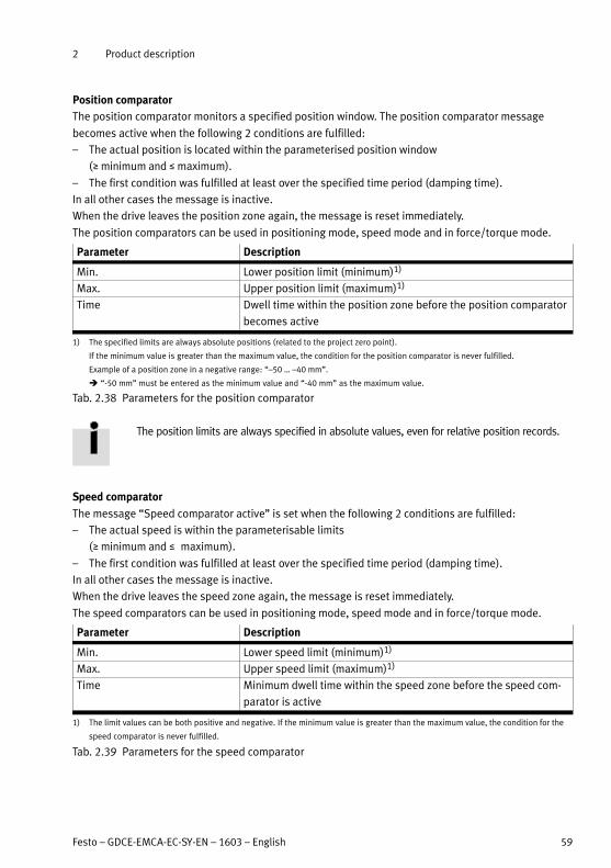
2 Product description
Festo – GDCE-EMCA-EC-SY-EN – 1603 – English 59
Position comparator
The position comparator monitors a specified position window. The position comparator message
becomes active when the following 2 conditions are fulfilled:
– The actual position is located within the parameterised position window
(› minimum and š maximum).
– The first condition was fulfilled at least over the specified time period (damping time).
In all other cases the message is inactive.
When the drive leaves the position zone again, the message is reset immediately.
The position comparators can be used in positioning mode, speed mode and in force/torque mode.
Parameter Description
Min. Lower position limit (minimum)1)
Max. Upper position limit (maximum)1)
Time Dwell time within the position zone before the position comparator
becomes active
1) The specified limits are always absolute positions (related to the project zero point).
If the minimum value is greater than the maximum value, the condition for the position comparator is never fulfilled.
Example of a position zone in a negative range: “–50 … –40 mm”.
“-50 mm” must be entered as the minimum value and “-40 mm” as the maximum value.
Tab. 2.38 Parameters for the position comparator
The position limits are always specified in absolute values, even for relative position records.
Speed comparator
The message “Speed comparator active” is set when the following 2 conditions are fulfilled:
– The actual speed is within the parameterisable limits
(› minimum and š maximum).
– The first condition was fulfilled at least over the specified time period (damping time).
In all other cases the message is inactive.
When the drive leaves the speed zone again, the message is reset immediately.
The speed comparators can be used in positioning mode, speed mode and in force/torque mode.
Parameter Description
Min. Lower speed limit (minimum)1)
Max. Upper speed limit (maximum)1)
Time Minimum dwell time within the speed zone before the speed com
parator is active
1) The limit values can be both positive and negative. If the minimum value is greater than the maximum value, the condition for the
speed comparator is never fulfilled.
Tab. 2.39 Parameters for the speed comparator
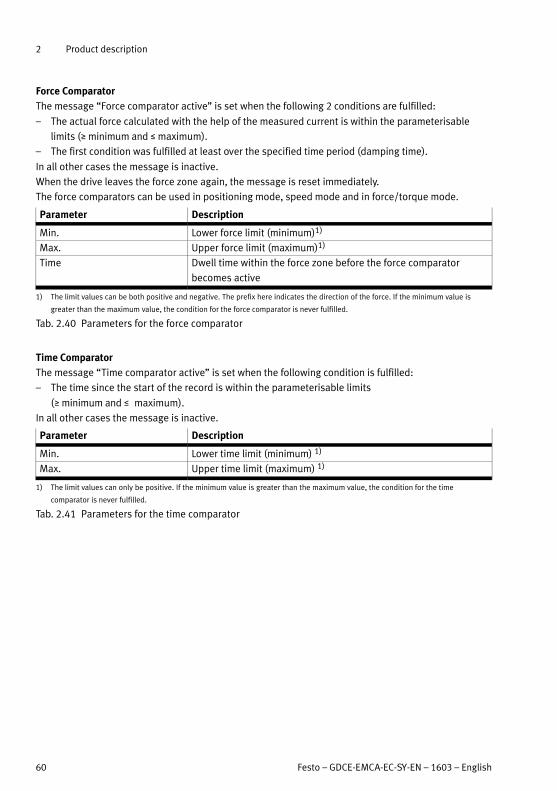
2 Product description
60 Festo – GDCE-EMCA-EC-SY-EN – 1603 – English
Force Comparator
The message “Force comparator active” is set when the following 2 conditions are fulfilled:
– The actual force calculated with the help of the measured current is within the parameterisable
limits (› minimum and š maximum).
– The first condition was fulfilled at least over the specified time period (damping time).
In all other cases the message is inactive.
When the drive leaves the force zone again, the message is reset immediately.
The force comparators can be used in positioning mode, speed mode and in force/torque mode.
Parameter Description
Min. Lower force limit (minimum)1)
Max. Upper force limit (maximum)1)
Time Dwell time within the force zone before the force comparator
becomes active
1) The limit values can be both positive and negative. The prefix here indicates the direction of the force. If the minimum value is
greater than the maximum value, the condition for the force comparator is never fulfilled.
Tab. 2.40 Parameters for the force comparator
Time Comparator
The message “Time comparator active” is set when the following condition is fulfilled:
– The time since the start of the record is within the parameterisable limits
(› minimum and š maximum).
In all other cases the message is inactive.
Parameter Description
Min. Lower time limit (minimum) 1)
Max. Upper time limit (maximum) 1)
1) The limit values can only be positive. If the minimum value is greater than the maximum value, the condition for the time
comparator is never fulfilled.
Tab. 2.41 Parameters for the time comparator
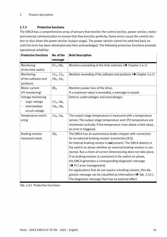
2 Product description
Festo – GDCE-EMCA-EC-SY-EN – 1603 – English 61
2.7.3 Protective functions
The EMCA has a comprehensive array of sensors that monitor the control section, power section, motor
and external communication to ensure that they function perfectly. Some errors cause the control sec
tion to shut down the power section (output stage). The power section cannot be switched back on
until the error has been eliminated and then acknowledged. The following protective functions promote
operational reliability:
Protective functions No. of the
message
Brief description
Monitoring
of the limit switch
07h, 08h Monitors exceeding of the limit switches ( Chapter 2.4.1)
Monitoring
of the software end
positions
11h, 12h,
29h, 2Ah
Monitors exceeding of the software end positions ( Chapter 2.4.1)
Motor current
(I²t monitoring)
0Eh Monitors power loss of the drive;
If a maximum value is exceeded, a message is issued.
Voltage monitoring Detects undervoltages and overvoltages
– Logic voltage 17h, 18h
– Intermediate
circuit voltage
1Ah, 1Bh
Temperature monit
oring
15h, 16h The output stage temperature is measured with a temperature
sensor. The output stage temperature and CPU temperature are
monitored cyclically. If the temperature rises above a limit value,
an error is triggered.
Braking resistor
measured value
30h The EMCA has an autonomous brake chopper with connection
for an external braking resistor (connection [X5]).
An internal braking resistor is not present. The EMCA detects in
the switch-on phase whether an external braking resistor is con
nected. But a check of correct dimensioning does not take place.
If no braking resistor is connected in the switch-on phase,
the EMCA generates a corresponding diagnostic message
( FCT error management).
For applications that do not require a braking resistor, this dia
gnostic message can be classified as information ( Tab. 2.43.).
The diagnostic message then has no external effect.
Tab. 2.42 Protective functions
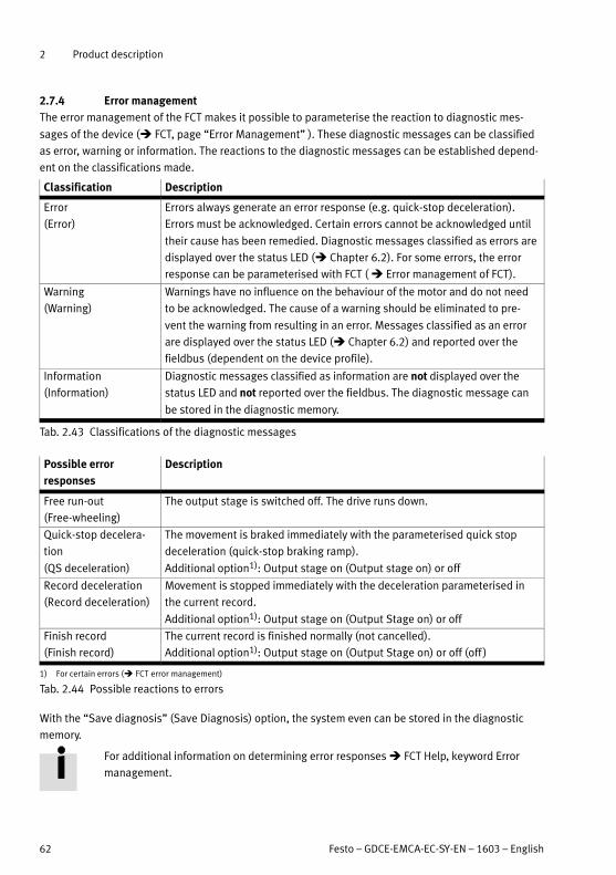
2 Product description
62 Festo – GDCE-EMCA-EC-SY-EN – 1603 – English
2.7.4 Error management
The error management of the FCT makes it possible to parameterise the reaction to diagnostic mes
sages of the device ( FCT, page “Error Management” ). These diagnostic messages can be classified
as error, warning or information. The reactions to the diagnostic messages can be established depend
ent on the classifications made.
Classification Description
Error
(Error)
Errors always generate an error response (e.g. quick-stop deceleration).
Errors must be acknowledged. Certain errors cannot be acknowledged until
their cause has been remedied. Diagnostic messages classified as errors are
displayed over the status LED ( Chapter 6.2). For some errors, the error
response can be parameterised with FCT ( Error management of FCT).
Warning
(Warning)
Warnings have no influence on the behaviour of the motor and do not need
to be acknowledged. The cause of a warning should be eliminated to pre
vent the warning from resulting in an error. Messages classified as an error
are displayed over the status LED ( Chapter 6.2) and reported over the
fieldbus (dependent on the device profile).
Information
(Information)
Diagnostic messages classified as information are not displayed over the
status LED and not reported over the fieldbus. The diagnostic message can
be stored in the diagnostic memory.
Tab. 2.43 Classifications of the diagnostic messages
Possible error
responses
Description
Free run-out
(Free-wheeling)
The output stage is switched off. The drive runs down.
Quick-stop decelera
tion
(QS deceleration)
The movement is braked immediately with the parameterised quick stop
deceleration (quick-stop braking ramp).
Additional option1): Output stage on (Output stage on) or off
Record deceleration
(Record deceleration)
Movement is stopped immediately with the deceleration parameterised in
the current record.
Additional option1): Output stage on (Output Stage on) or off
Finish record
(Finish record)
The current record is finished normally (not cancelled).
Additional option1): Output stage on (Output Stage on) or off (off )
1) For certain errors ( FCT error management)
Tab. 2.44 Possible reactions to errors
With the “Save diagnosis” (Save Diagnosis) option, the system even can be stored in the diagnostic
memory.
For additional information on determining error responses FCT Help, keyword Error
management.
2 Product description
Festo – GDCE-EMCA-EC-SY-EN – 1603 – English 63
2.7.5 Diagnostic memory
The EMCA has a non-volatile diagnostic memory. Diagnostic messages can be recorded in the diagnost
ic memory. Which diagnostic messages get recorded can be defined through the FCT error management
function ( Chapter 2.7.4).
The diagnostic memory is designed as a ring memory with a capacity of 200 diagnostic messages.
The relevant diagnostic messages are written consecutively to the diagnostic memory. Whenever the
diagnostic memory is full, the oldest diagnostic message is overwritten when a new diagnostic mes
sage arrives (FIFO principle).
The diagnostic memory can be accessed by:
– Fieldbus ( Description for the device profile used)
– FCT (see FCT help)
– Webserver ( Chapter 5.5 and 6.1).

2 Product description
64 Festo – GDCE-EMCA-EC-SY-EN – 1603 – English
2.8 Interfaces
The device has a parameterisation interface and a control interface. The parameterisation interface is
executed as an Ethernet interface ( Chapter 2.8.1). Execution of the control interface is dependent on
the product design:
– EMCA-EC...-CO: CANopen
Information for installation Chapter 4
2.8.1 Parameterisation interface [X1] (Ethernet interface)
The parameterisation interface [X1] permits the following:
– Configuration, parameterisation, commissioning, diagnostics and firmware download with FCT
( Chapter 5.2 and FCT Help)
– Diagnostics with the help of the web server via a web browser ( Chapter 5.5 and 6.1)
– Loading a parameter file via the web server ( Chapter 5.7) and with FCT
Through the Ethernet interface, the following connections are possible:
Connections Description
Point-to-pointconnection
The device is connected directly to the PC via an Ethernet cable.
Network connection The device is connected to an Ethernet network.
Tab. 2.45 Options for connection
The device supports the following 3 methods of the IP configuration (based on IPv4):
Methods Description
Active DHCP server
(factory setting)
The device has a permanently parameterised IP configuration. If a PC con
figured as a DHCP client is connected to the device, the device automatic
ally assigns an IP configuration to the PC. This method is especially suited
for point-to-point connections.
IP configuration with active DHCP server:
– IP address: 192.168.178.1
– Subnet mask: 255.255.255.0
– Gateway: – (a gateway is not assigned)
Obtain IP address
automatically
(DHCP client)
The device obtains its IP configuration from a DHCP server in your network.
This method is especially suitable for networks in which another DHCP
server already exists.
Fixed IP configuration The IP configuration of the device can be permanently assigned manually.
However, the device can only be addressed if the assigned IP configuration
matches the IP configuration of the PC.
Tab. 2.46 Options for IP configuration

2 Product description
Festo – GDCE-EMCA-EC-SY-EN – 1603 – English 65
FCT offers a search function (network scan) with which a device can be found in the network without
knowledge of the current IP configuration. If the device has been found, the method of the IP configura
tion can be established with FCT.
– The IP configuration on the device can be changed without the current IP configuration of the device
matching the IP configuration of the PC.
– The waving function (flashing of an LED) of the device can be activated and deactivated. With this,
a device can be optically identified from a number of devices.
2.8.2 Control interface [X2], [X3] (fieldbus)
With a high level at the Control enable input [X9.4], the control interface enables complete control of
the device.
The connection [X2] permits connection of the incoming bus line. The connection [X3] permits connec
tion of the continuing bus line ( Chapter 4.4).
For additional information Description for the respective device profile:
– Description of device profile FHPP, GDCE-EMCA-EC-HP-...
– Description of device profile CiA 402, GDCE-EMCA-EC-CO-...
Terminating resistor for the CAN bus (only for EMCA-...-CO)
The line ends of bus lines must be equipped with a terminating resistor. The device is equipped with
a terminating resistor for the CAN bus. The terminating resistor can be activated or deactivated with
the DIP switch ( Fig. 2.4, 3). For additional information Tab. 4.8.
2.8.3 STO interface [X6]
The STO interface [X6] permits the 2-channel shut-down of the motor torque (function “securely
switched-off torque” (Safe torque off/STO)).
The STO safety function (Safe torque off ) is described in detail in the document
GDCE-EMCA-EC-S1-.... The safety function STO should only be used in the manner
described in this document. Additional information Description of STO safety function,
GDCE-EMCA-EC-S1-....

2 Product description
66 Festo – GDCE-EMCA-EC-SY-EN – 1603 – English
2.8.4 Functions of the base inputs/outputs
Functions of the digital base inputs (6)
Pin Name Function
[X6.4] STO 1 (Safe torque
off channel 1)
Control port STO channel 1
( Description of the safety function STO, GDCE-EMCA-EC-S1-....)
[X6.5] STO 2 (Safe torque
off channel 2)
Control port STO channel 2
( Description of the safety function STO, GDCE-EMCA-EC-S1-....)
[X7.2] Switch 1 Input for reference switch or end switch 1
With the configured edge of switch 1, reaching of the reference/end
position is signaled.1)
[X8.2] Switch 2 Input for reference switch or end switch 2
With the configured edge of switch 2, reaching of the reference/end
position is signaled.1)
[X9.4] Control enable – High level: Permit controller enable over the interface that has
master control ( Fig. 2.18)
– Low level: Block controller; causes the controlled braking with the
parameterised quick-stop deceleration ( Fig. 2.18).
[X9.5] Sample Signal for storing the actual position (flying measurement)
The current actual position of the drive is saved with an edge change.
Rising and falling edges have their own memories ( Tab. 2.49).
The higher-order controller can thus call up the two last stored actual
position via the active fieldbus.
1) Switch function (reference switch or limit switch) and switch type (normally closed or normally open) are configurable with FCT.
Tab. 2.47 Functions of the digital base inputs – connections [X6], [X7], [X8] and [X9]
Functions of the digital base outputs (2)
Pin Name Function
[X9.1] Ready Signals the ready status of the device
– High level: Device is ready for operation (ready for operation/no
error); the output delivers high level as long as all of the following
conditions are met:
– At the input Control enable, high level is present.
– Controller enable over the interface is present with master
control.1)
– No error message is present.
– Low level: Device is not ready to operate/error.
[X9.2] configurable Output behavior configurable with FCT: depictable signals
Tab. 2.50
1) Description for the device profile used and Help for the EMCA plug-in.
Tab. 2.48 Functions of the digital base outputs – connection [X9]

2 Product description
Festo – GDCE-EMCA-EC-SY-EN – 1603 – English 67
Enable logic of controller enable
First, the required signal must be present at the input “Control enable” [X9.4]. Then, the controller
enable can be requested over the interface that has master control (edge control).
In case of transfer of master control through FCT, the current enable signal of the control interface.
Detailed information on controller enable Description for the device profile used and
Help for the EMCA plug-in.
Behaviour with controller enable
If controller enable is present, the controller is enabled and the position controller activated (actual
position = setpoint position).
Removal of controller enable
Removal of the controller enable stops the ongoing order (quick stop). If the search speed v=0,
the “Ready” signal is reset and the controller blocked. For product designs without a holding brake,
the drive is then freely movable.

2 Product description
68 Festo – GDCE-EMCA-EC-SY-EN – 1603 – English
Input Control enable
Controller enable can be requested immediately after the power supply is switched on. The EMCA
reports back “Ready” when it is ready for operation. For controller enable to be created through the
interface with master control, the enable signal must be present at the “Control enable” input [X9.4].
– High level permits release of the controller over the control interface ( Description for the respect
ive device profile) or the parameterisation interface ( Plug-in Help for the EMCA).
– Low level blocks the controller. No additional positioning tasks will then be accepted.
65
Device status of controller Block BlockEnable
41 2 3
Controller enable onOff
Ready (DOUT)
Holding brake openedClosed
t1
Power supply onOff
No errorError
Control enable (DIN)
Vset = 0
Quick stop
t2
Delay times:
t1: Depending on the parameterised switch-on delay
t2: Depending on the parameterised switch-off delay
1 Switch on the power supply
2 Request controller enable
3 Ready to operate
4 Revoke controller enable (quick stop)
5 Holding brake is closed
6 Controller disabled
Fig. 2.18 Time diagram, create ready status – example
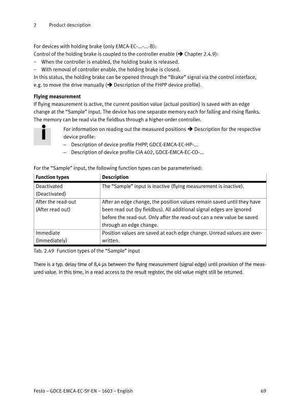
2 Product description
Festo – GDCE-EMCA-EC-SY-EN – 1603 – English 69
For devices with holding brake (only EMCA-EC-...-...-B):
Control of the holding brake is coupled to the controller enable ( Chapter 2.4.9):
– When the controller is enabled, the holding brake is released.
– With removal of controller enable, the holding brake is closed.
In this status, the holding brake can be opened through the “Brake” signal via the control interface,
e.g. to move the drive manually ( Description of the FHPP device profile).
Flying measurement
If flying measurement is active, the current position value (actual position) is saved with an edge
change at the “Sample” input. The device has one separate memory each for falling and rising flanks.
The memory can be read via the fieldbus through a higher-order controller.
For information on reading out the measured positions Description for the respective
device profile:
– Description of device profile FHPP, GDCE-EMCA-EC-HP-...
– Description of device profile CiA 402, GDCE-EMCA-EC-CO-...
For the “Sample” input, the following function types can be parameterised:
Function types Description
Deactivated
(Deactivated)
The “Sample” input is inactive (flying measurement is inactive).
After the read-out
(After read out)
After an edge change, the position values remain saved until they have
been read out (by fieldbus). All additional signal edges are ignored
before the read-out. Only after the read-out can a new value be saved
through an edge change.
Immediate
(Immediately)
Position values are saved at each edge change. Unread values are over
written.
Tab. 2.49 Function types of the “Sample” input
There is a typ. delay time of 8,4 μs between the flying measurement (signal edge) until provision of the meas
ured value. In this time, in a read access to the result register, the old value might still be returned.

2 Product description
70 Festo – GDCE-EMCA-EC-SY-EN – 1603 – English
Freely configurable digital output
The freely configurable digital output [X9.2] can depict one of the following signals:
Group Function Output supplies …
– Output high … always high level.
Output low … always low level.
Motion
(Motion)
Motion Complete (actual
value)
… High level, if the actual value of the current record
is in the time window.
Motion Complete (set
point value)
… High level, if the setpoint value of the current
record is in the time window.
Axis In motion … High level, if the axis moves.
Constant speed reached … High level, if the target speed or maximum speed
of the current record is reached.
Force limit reached … High level, if the force limit specified in the record
has been reached.
Standstill monitoring … High level, if the “Standstill monitoring” message
is active.
Homing
(Homing)
Homing active … High level, if homing is being carried out.
Reference position valid … High level, if reference position is valid.
Comparators
(Comparators)
Position comparator … High level, if the corresponding comparator is
active.1)Speed comparator
Force comparator
Time comparator
Errors/warnings
(Errors/Warnings)
Common error (low active) … Low level, if at least one error is reported.
Following error … High level, if the corresponding message is active.2)
I²t Error
I²t warning
Load overvoltage
Load undervoltage
1) Detailed information on comparators Chapter 2.7.2.
2) Information on protective functions Chapter 2.7.3.
Tab. 2.50 Functions of the freely configurable digital output

3 Mounting
Festo – GDCE-EMCA-EC-SY-EN – 1603 – English 71
3 Mounting
3.1 Dimensions
Type Dimen
sion
L1 L2 L3 L4 L5 L6
EMCA-...-S-... [mm] 169.9 +0.8/-1.1 25 ±0.5 117.2 -0.3 52.7 ±0.8 4.7 ±0.3 3 -0.1
EMCA-...-M-... 187.4 +0.8/-1.1 70.2 ±0.8
Dimen
sion
H1 H2 B1 D1 D2 D3 D4 D5
[mm] 121.1 ±0.5 67 67 @ 9 -0.009 @ 40 -0.039 @ 81 ±0.2 @ 50 ±0.2 @ 6.3 ±0.2
Tab. 3.1 Dimensions
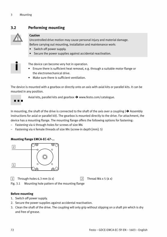
3 Mounting
72 Festo – GDCE-EMCA-EC-SY-EN – 1603 – English
3.2 Performing mounting
Caution
Uncontrolled drive motion may cause personal injury and material damage.
Before carrying out mounting, installation and maintenance work:
Switch off power supply.
Secure the power supplies against accidental reactivation.
The device can become very hot in operation.
Ensure there is sufficient heat removal, e.g. through a suitable motor flange or
the electromechanical drive.
Make sure there is sufficient ventilation.
The device is mounted with a gearbox or directly onto an axis with axial kits or parallel kits. It can be
mounted in any position.
Axial kits, parallel kits and gearbox www.festo.com/catalogue.
In mounting, the shaft of the drive is connected to the shaft of the axis over a coupling ( Assembly
instructions for axial or parallel kit). The gearbox is mounted directly to the drive. For attachment, the
device has a mounting flange. The mounting flange offers the following options for fastening:
– Fastening via 4 through-holes for screws of size M6
– Fastening via 4 female threads of size M4 (screw-in depth [mm]: 5)
Mounting flange EMCA-EC-67-...
2
1
1 Through-holes 6.3 mm (4 x) 2 Thread M4 x 5 (4 x)
Fig. 3.1 Mounting hole pattern of the mounting flange
Before mounting
1. Switch off power supply.
2. Secure the power supplies against accidental reactivation.
3. Clean the shaft of the drive. The coupling will only grip without slipping on a shaft pin which is dry
and free of grease.

3 Mounting
Festo – GDCE-EMCA-EC-SY-EN – 1603 – English 73
Mounting
Note
Excessive axial and radial forces on the motor shaft can damage the motor.
Comply with max. permissible shaft loads ( Technical data for the integrated
motor in Appendix A.1.5).
Observe the assembly instructions for the additional components used (e.g. axial kit,
parallel kit, gear unit, shaft). Observe the assembly instructions of the lines regarding
bending radii or suitability for energy chains.
The drive must be mounted securely and free of tension.
1. Move the slide or cantilever of the driven mechanical system into a safe position.
2. Connect the EMCA to the driven mechanical system ( Assembly instructions of the additional
components used).
3. Tighten the mounting screws (4x). Tightening torque Assembly instructions of the additional
components used.
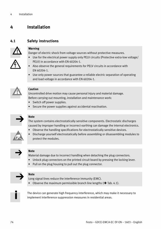
4 Installation
74 Festo – GDCE-EMCA-EC-SY-EN – 1603 – English
4 Installation
4.1 Safety instructions
Warning
Danger of electric shock from voltage sources without protective measures.
Use for the electrical power supply only PELV circuits (Protective extra-low voltage/
PELV) in accordance with EN 60204-1.
Also observe the general requirements for PELV circuits in accordance with
EN 60204-1.
Use only power sources that guarantee a reliable electric separation of operating
and load voltage in accordance with EN 60204-1.
Caution
Uncontrolled drive motion may cause personal injury and material damage.
Before carrying out mounting, installation and maintenance work:
Switch off power supplies.
Secure the power supplies against accidental reactivation.
Note
The system contains electrostatically sensitive components. Electrostatic discharges
caused by improper handling or incorrect earthing can damage the internal electronics.
Observe the handling specifications for electrostatically sensitive devices.
Discharge yourself electrostatically before assembling or disassembling modules to
protect the modules.
Note
Material damage due to incorrect handling when detaching the plug connectors.
Unlock plug connectors on the printed circuit board by pressing the locking lever.
Pull on the plug housing to pull out the plug connector.
Note
Long signal lines reduce the interference immunity (EMC).
Observe the maximum permissible branch line lengths ( Tab. 4.1).
The device can generate high frequency interference, which may make it necessary to
implement interference suppression measures in residential areas.

4 Installation
Festo – GDCE-EMCA-EC-SY-EN – 1603 – English 75
4.2 EMC-compliant wiring
Earth/ground:
Connect the motor flange to the earth potential with low impedance (short cable with
large cross section) if the motor flange is not mounted to an earthed machine frame
through an electromechanical drive.
If a screened supply cable is to be used, place the cable screening on the functional
earth connection (flat plug).
Routing cables:
Comply with general guidelines for EMC-appropriate installation, e.g.:
Do not run signal cables parallel to power cables.
Comply with required minimum distances between signal cables and power cables
dependent on the installation conditions.
Avoid crossing power cables or running them at a 90° angle.
Comply with permissible cable lengths ( Tab. 4.1).
Connec
tion
Interface Cable length [m] Screening
[X1] Ethernet interface Max. 1001) – Screened copper connecting cable,
4-conductor; Ethernet twisted pair
cable ( Tab. 4.4)
[X2] EMCA-...-CO: CAN IN 40 at 1 Mbit/s2) – Screened3)
[X3] EMCA-...-CO: CAN OUT 40 at 1 Mbit/s2)
[X4] Power supply 30 – Unshielded
– A screened cable can optionally be
used. In this case, the cable screen
ing can be attached to the flat plug
on the device side ( Tab. 4.11).
[X5] Braking resistor 3 – Unshielded
[X6] STO interface 30
[X7]
[X8]
End/reference switch 3
[X9] I/O interface 30
[X10] External battery 3
1) Between the network participants
2) The permissible total line length of the fieldbus at a bit rate of 1 Mbit/s. Observe specifications in the documentation of your
control system or bus interface.
3) Cable specifications Description for the respective device profile
Tab. 4.1 Information for EMC-compliant wiring

4 Installation
76 Festo – GDCE-EMCA-EC-SY-EN – 1603 – English
4.3 Parameterisation interface [X1]
The parameterisation interface (Ethernet interface) on the top of the connection box permits connec
tion to a PC or a network.
Note
Unauthorised access to the device can cause damage or malfunctions. When connect
ing the device to a network:
Protect the network from unauthorised access.
Measures for protecting the network include:
– Firewall
– Intrusion prevention system (IPS)
– Network segmentation
– Virtual LAN (VLAN)
– Virtual Private Network (VPN)
– Security at physical access level (port security)
Additional information Guidelines and standards for security in information techno
logy, e.g. IEC 62443, ISO/IEC 27001.
Connection Design
[X1] on the device M12 socket, 5-pin, D-coded
Counterplug Plug M12, 4- or 5-pin, D-coded
Tab. 4.2 Design of the connection [X1]
1
1 Ethernet interface [X1]
[X1] Pin Designation Description
1 TD+ Transmitted data +
2 RD+ Received data +
3 TD- Transmitted data –
4 RD- Received data –
5 – Not connected
Housing Shield/FE Shield/functional earth
Tab. 4.3 Connection of parameterisation interface [X1] (Ethernet)
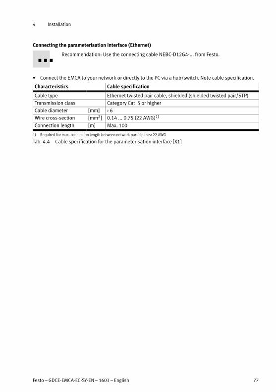
4 Installation
Festo – GDCE-EMCA-EC-SY-EN – 1603 – English 77
Connecting the parameterisation interface (Ethernet)
Recommendation: Use the connecting cable NEBC-D12G4-... from Festo.
Connect the EMCA to your network or directly to the PC via a hub/switch. Note cable specification.
Characteristics Cable specification
Cable type Ethernet twisted pair cable, shielded (shielded twisted pair/STP)
Transmission class Category Cat 5 or higher
Cable diameter [mm] 6
Wire cross-section [mm2] 0.14 ... 0.75 (22 AWG)1)
Connection length [m] Max. 100
1) Required for max. connection length between network participants: 22 AWG
Tab. 4.4 Cable specification for the parameterisation interface [X1]
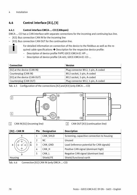
4 Installation
78 Festo – GDCE-EMCA-EC-SY-EN – 1603 – English
4.4 Control interface [X1], [3]
4.4.1 Control interface EMCA-...-CO (CANopen)
EMCA-...-CO has a CAN interface with separate connections for the incoming and continuing bus line.
– [X2]: Bus connection CAN IN for the incoming line
– [X3]: Bus connection CAN OUT for the continuation line.
For detailed information on connection of the device to the fieldbus as well as the re
quired cable specifications Description for the respective device profile:
– Description of device profile FHPP, GDCE-EMCA-EC-HP-...
– Description of device profile CiA 402, GDCE-EMCA-EC-CO-...
Connection Version
[X2] at the device (CAN IN) Plug connector M12, 5-pin, A-coded
Counterplug (CAN IN) M12 socket, 5-pin, A-coded
[X3] at the device (CAN OUT) M12 socket, 5-pin, A-coded
Counterplug (CAN OUT) Plug connector M12, 5-pin, A-coded
Tab. 4.5 Configuration of the connections [X2] and [X3] (only EMCA-...-CO)
1
2
1 CAN IN [X2] (incoming line) 2 CAN OUT [X3] (continuation line)
[X2] – CAN IN Pin Designation Description
1 CAN_SHLD Screening, capacitive connection to housing
2 NC Unused
3 CAN_GND Load (reference potential for CAN signals)
4 CAN_H Positive CAN signal (dominant high)
5 CAN_L Negative CAN signal (dominant low)
Housing Shield/FE Shield/functional earth
Tab. 4.6 Connection [X2] CAN IN (only EMCA-...-CO)

4 Installation
Festo – GDCE-EMCA-EC-SY-EN – 1603 – English 79
[X3] – CAN OUT Pin Designation Description
1 CAN_SHLD Screening, capacitive connection to housing
2 NC Unused
3 CAN_GND Load (reference potential for CAN signals)
4 CAN_H Positive CAN signal (dominant high)
5 CAN_L Negative CAN signal (dominant low)
Housing Shield/FE Shield/functional earth
Tab. 4.7 Connection [X3] CAN OUT (only EMCA-...-CO)
Terminating resistor for CAN bus
The device is equipped with a terminating resistor for the CAN bus. The terminating resistor can be
switched on or off with the DIP switch S1.1 ( Fig. 2.4, 3).
DIL switches Function
S1.1 Terminating resistor (120 Ω); ON = ON, OFF = OFF
S1.2 Reserved (without function)
Tab. 4.8 Terminating resistor (only EMCA-...-CO)
For additional information Description for the respective device profile:
– Description of device profile FHPP, GDCE-EMCA-EC-HP-...
– Description of device profile CiA 402, GDCE-EMCA-EC-CO-...

4 Installation
80 Festo – GDCE-EMCA-EC-SY-EN – 1603 – English
4.5 Connection of the plug connectors [X4] ... [X10]
The connections [X4] to [X10] are designed as plug connectors and are located inside the connection
box. The following table provides an overview of the respective cable specifications.
Overview of cable specifications1)2)
Connection [X4] [X5] [X6] [X7], [X8] [X9] [X10]
Power
supply
Braking
resistor
STO (Safe
torque off )
End/refer
ence switch
I/O inter
face
External
battery
Manufac
turer3)
JST Tyco Electronics AMP JST
Plug connector B2P-VH-FB-
B-C
B2P-VH-
FB-B
3-794636-6 2-1445053-3 3-794636-6 B2B-ZR-
SM4-TF
Counterplug VHR-2N-BK
(Black)
VHR-2N
(White)
794617-6 1445022-3 794617-6 ZHR-2
Crimp contact SVH-41T-P1.1 AWG24 ... AWG20:
– 794606-1 (strips)
– 794610-1 (loose)
AWG30 ... AWG26:
– 794607-1 (strips)
– 794611-1 (loose)
SZH-002T-P0,5
Crimp pliers WC-930 or YC-930R 91501-1 (AWG24 ... AWG20)
91502-1 (AWG30 ... AWG26)
YRS-491,WC-491 orWC-ZH2632
Strip length Observe current specifications/crimp instructions of the manufacturer of the plug
connectors!
Diameter of
the cable insu
lation sheath
[mm]
1.7 ... 3 0.89 ... 1.53 0.8 ... 1.1
Wire cross-
section
[mm²]
0.5 ... 1.25
(AWG20 ... AWG16)
0.2 ... 0.5 (AWG24 ... AWG20)
0.05 ... 0.12 (AWG30 ... AWG26)
0.08 ... 0.13
(AWG28 ...
AWG26)
Cable outside
diameter
Seal elements for the following cable diameters are included in the scope of delivery:
2.9 … 3.0 mm, 6.5 … 7.1 mm, 9.1 … 9.6 mm
Cable type Unshiel
ded4)
Unshielded
1) Includes specifications of manufacturers of plug connectors and crimp contacts at the time the document was released
2) Observe current specifications/crimp instructions of the named manufacturers!
3) Manufacturer of the plug connectors, counterplugs and crimp contacts
4) Optional: screened ( Tab. 4.1)
Tab. 4.9 Overview of cable specifications
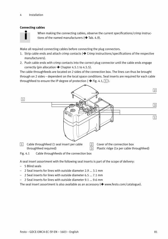
4 Installation
Festo – GDCE-EMCA-EC-SY-EN – 1603 – English 81
Connecting cables
When making the connecting cables, observe the current specifications/crimp instruc
tions of the named manufacturers ( Tab. 4.9).
Make all required connecting cables before connecting the plug connectors.
1. Strip cable ends and attach crimp contacts ( Crimp instructions/specifications of the respective
manufacturers).
2. Push cable ends with crimp contacts into the correct plug connector until the cable ends engage
correctly (pin allocation Chapter 4.5.1 to 4.5.5).
The cable throughfeeds are located on 2 sides of the connection box. The lines can thus be brought
through on 2 sides – dependent on the local space conditions. Seal inserts are required for each cable
throughfeed to ensure the IP degree of protection ( Fig. 4.1, 1 ).
1
1
2
3
1 Cable throughfeed (1 seal insert per cable
throughfeed required)
2 Cover of the connection box
3 Plastic ridge (1x per cable throughfeed)
Fig. 4.1 Cable throughfeeds of the connection box
A seal insert assortment with the following seal inserts is part of the scope of delivery:
– 5 Blind seals
– 2 Seal inserts for lines with outside diameter 2.9 ... 3.1 mm
– 2 Seal inserts for lines with outside diameter 6.5 ... 7.1 mm
– 2 Seal inserts for lines with outside diameter 9.1 ... 9.6 mm
The seal insert assortment is also available as an accessory ( www.festo.com/catalogue).

4 Installation
82 Festo – GDCE-EMCA-EC-SY-EN – 1603 – English
Connecting the internal plug connectors
For electrical installation, the cover of the connection box must be dismounted.
Before dismounting the cover:
1. Switch off the power supply.
2. Protect the device against being switched on again.
Note
The EMCA contains electrostatically sensitive devices. Electrostatic discharges caused
by improper handling or incorrect earthing can damage the internal electronics.
Observe the handling specifications for electrostatically sensitive devices.
Discharge yourself electrostatically before assembling or disassembling modules
to protect the modules.
For electrical installation:
When mounting seal inserts and the cover, make sure the seals are clean.
1. If the cover of the connection box is already mounted, loosen the cover with an Allen key (width
across flats (SW) 2.5 mm) and carefully remove the cover.
2. Place seal inserts around the line.
3. With pliers, break out plastic ridges of the cable throughfeeds ( Fig. 4.1, 3).
4. Push line with seal insert into the respective cable throughfeed – depending on the space condi
tions.
5. Connect lines correctly (pin allocation Chapter 4.5.1 to 4.5.5).
6. Push in all plug connectors until the plugs engage.
To release plug connectors on the printed circuit board:
Unlock plug connectors by pressing the locking lever and pull them out on the plug housing.
7. Seal unused cable throughfeeds with blind seals.
8. Position cover of the connection box correctly. Make sure the seal is seated correctly.
9. Tighten the cover with the 4 included screws – tightening torque 1.5 Nm.

4 Installation
Festo – GDCE-EMCA-EC-SY-EN – 1603 – English 83
4.5.1 Power supply [X4]
Warning
Danger of electric shock from voltage sources without protective measures.
Use for the electrical power supply only PELV circuits (Protective extra-low voltage/
PELV) in accordance with EN 60204-1.
Also observe the general requirements for PELV circuits in accordance with
EN 60204-1.
Use only power sources that guarantee a reliable electric separation of operating
and load voltage in accordance with EN 60204-1.
Through the use of PELV circuits, protection from electric shock (protection from direct and indirect
contact) in accordance with EN 60204-1 is ensured (Electrical equipment of machines. General require
ments). A 24 V power supply unit used in the system must satisfy the requirements of EN 60204-1 for
DC power supply (behaviour during power interruptions, etc.).
[X4] Pin Description
1 +24 V DC Power supply (logic and load voltage)
19.2 V DC … 28.8 V DC
2 0 V GND, reference potential
Tab. 4.10 Pin allocation of power supply [X4]
If a screened supply cable is used, the cable screening can be placed on the functional earth connection
(flat plug).
Flat pin Pin Description
- FE Optional connection for the cable screening if a screened
supply cable is to be used
Counterplug: flat connector sleeve (6.3 x 0.8 mm²)
Tab. 4.11 Flat plug (FE) – optional

4 Installation
84 Festo – GDCE-EMCA-EC-SY-EN – 1603 – English
Connection to the supply voltage
Before establishing the connection make sure the power supply is switched off.
EMCA
[X4]
1
2
1
2+24 V DC
0 V
1 Integrated drive EMCA 2 Power supply unit 24 V DC
Fig. 4.2 Connection to the supply voltage

4 Installation
Festo – GDCE-EMCA-EC-SY-EN – 1603 – English 85
4.5.2 Braking resistor [X5]
The drive of the EMCA supplies energy back into the intermediate circuit of the device during braking or
with independent excitation. Excess energy must be absorbed by a braking resistor, which must be
attached externally, and converted into heat energy to avoid impermissibly high voltages. An internal
braking resistor is not present ( Tab. 2.42).
Note
Impermissibly high voltages can result from feeding energy back into the intermediate
circuit of the device. This can damage the device and cause malfunctions.
Connect a braking resistor adapted to the braking output that occurs in the desired
application.
[X5] Pin Description
1 IC+ Connection for the external braking resistor RBR 6 Ω
2 BR-CH
Tab. 4.12 Pin allocation for braking resistor [X5]
The braking resistor CACR-LE2-6-W60 from Festo is suitable (6 Ω/60 W).

4 Installation
86 Festo – GDCE-EMCA-EC-SY-EN – 1603 – English
4.5.3 STO interface [X6]
The safety function STO (Safe torque off ) is described in detail in the document
GDCE-EMCA-EC-S1-.... The safety function STO should only be used in the manner
described in this document.
[X6] Pin Designation Description
1 NC1 Acknowledgment contact:
– Potential-free
– Low impedance if the STO function has been requested
and activated via two channels.
2 NC2
3 +24 V DC
LOGIC OUT
Logic voltage output (from [X4]), reference potential (0 V) is
pin [X6.6] or [X4.2] (internally bridged)
Not overload-proof! Max. 100 mA permissible.
4 STO 1 Control ports for STO function1)
5 STO 2
6 GND Reference potential 0 V
1) In the web server, assigned to the Basic IO Interface ( web server).
Tab. 4.13 Pin assignment of STO interface (Safe torque off ) [X6]

4 Installation
Festo – GDCE-EMCA-EC-SY-EN – 1603 – English 87
4.5.4 Limit or reference switch [X7], [X8]
The connections [X7] and [X8] permit connection of 3-pin limit or reference switch ( Tab. 4.14 and
Tab. 4.15). As a result, each device can connect to a maximum of 2 limit switches or 1 limit switch and 1
reference switch.
[X7] Pin Description
1 +24 V DC Voltage output 24 V for supply of the reference or limitswitch 1 (configurable with FCT, not short-circuit safe)
2 Switch 1 Signal input for reference switch or limit switch 1
3 GND Reference potential 0 V
Tab. 4.14 Pin allocation of reference or limit switch 1 [X7]
[X8] Pin Description
1 +24 V DC Voltage output 24 V for supply of the reference or limitswitch 2 (configurable with FCT, not short-circuit safe)
2 Switch 2 Signal input for reference switch or limit switch 2
3 GND Reference potential 0 V
Tab. 4.15 Pin allocation of reference or limit switch 2 [X8]

4 Installation
88 Festo – GDCE-EMCA-EC-SY-EN – 1603 – English
4.5.5 I/O interface [X9]
The remaining digital I/Os are brought together on connection [X9].
[X9] Pin Type1)
Name Description
1 DOUT Ready Signals the ready status
2 DOUT configurable Output behavior configurable with FCT
3 – +24 V DC Output 24 V DC, looped through from [X4.1]
4 DIN Control enable Enable/block controller
5 DIN Sample Signal for storing the actual position
(flying measurement)
6 – GND Reference potential 0 V
1) DIN = digital input; DOUT = digital output
Tab. 4.16 Pin allocation for I/O interface (PNP logic)
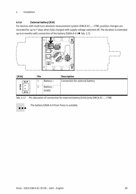
4 Installation
Festo – GDCE-EMCA-EC-SY-EN – 1603 – English 89
4.5.6 External battery [X10]
For devices with multi-turn absolute measurement system (EMCA-EC-...-1TM), position changes are
recorded for up to 7 days when fully charged with supply voltage switched off. The duration is extended
up to 6 months with connection of the battery EADA-A-9 ( Tab. 2.7).
[X10] Pin Description
1 Battery + Connection for external battery
2 Battery –
(GND)
Tab. 4.17 Pin allocation of connection for external battery [X10] (only EMCA-EC-...-1TM)
The battery EADA-A-9 from Festo is suitable.

4 Installation
90 Festo – GDCE-EMCA-EC-SY-EN – 1603 – English
4.6 Requirements for ensuring IP degree of protection
Use only connection technology with the corresponding IP degree of protection ( www.festo.com/
catalogue).
Use cover caps to seal unused connections. When doing this, make sure the seals are clean!
The M12 connections of the device are equipped with O-rings, which ensure the IP degree of protec
tion stated in the Technical data in combination with the following cover caps (included in delivery):
– Connection [X1] and [X3]: cover cap ISK-M12
– Connection [X2]: protective cap M12, pin
To connect the plug connector (connection [X4] to [X10]), use only cable with suitable outside dia
meter and circular cross section, so that the sealing kits can seal correctly.
Seal cable throughfeeds of the connection box with the accompanying seal inserts. When doing
this, make sure the seals and lines are clean! Replace damaged seals.
Current information on accessories www.festo.com/catalogue.
5 Commissioning
Festo – GDCE-EMCA-EC-SY-EN – 1603 – English 91
5 Commissioning
5.1 Notes on commissioning
Caution
Rapidly rotating motor shaft with high torque.
Contact with the motor shaft can cause burn injuries and abrasions.
Ensure that the rotating motor shaft and components attached to it cannot be
touched.
Warning
Rapidly rotating motor shaft with high torque.
Clothing, jewellery and hair can be caught and wrapped around the shaft. People can be
injured as a result.
Make sure that clothing, jewellery or hair can not be caught by the rotating motor
shaft.
Ensure that clothing fits tightly.
Hair nets must be worn with long hair.
Warning
Danger of burns from hot housing surfaces.
Contact with the motor housing can cause burn injuries. This can frighten people and
cause them to act in an unpredictable manner. This can lead to other forms of secondary
damage.
Make sure that unintentional contact is not possible.
Inform operating and maintenance staff about the possible hazards.
5.2 FCT (Festo Configuration Tool)
The following pages only describe the first few steps in FCT. Implement all other steps in
accordance with the instructions in the integrated FCT help system.
5.2.1 Installing FCT
Note
The FCT plug-in EMCA V 1.0.0 supports devices with firmware version V1.0.x. or later.
With more recent firmware designs, check whether an updated plug-in is available
( www.festo.com/sp).

5 Commissioning
92 Festo – GDCE-EMCA-EC-SY-EN – 1603 – English
Note
Windows administrator rights are required for installing the FCT.
The FCT is installed on your PC with an installation program.
1. Before installation, close all programs.
2. Start installation program (Setup_EMCA....exe).
3. Follow the instructions of the FCT Assistant.
5.2.2 Starting the FCT
Start FCT as follows:
Double click on the FCT icon on the desktop
Or in the Windows start menu, select the following menu path:
[Programs] [Festo Software] [Festo Configuration Tool].
To be able to create a connection to the device, a project must be created or opened in the FCT.
5.2.3 Notes on commissioning with FCT
FCT framework
For information on working with projects and adding a device to a project to a project Help for the
FCT Framework (command [Help] [Contens FCT general]).
EMCA plug-in
The EMCA plug-in for the FCT supports all the steps necessary for commissioning of the device. The
necessary parameterisations can be executed on the PC offline and later transferred to the device. This
enables preparation for the actual commissioning process, e.g. in the design office when a new system
is being planned.
FCT Help
For detailed information about configuration, parameterisation and commissioning Plug-in Help.
– Command [Help] [Contents of installed PlugIns] [Festo] [EMCA]
The FCT Help also has information about possible commissioning scenarios and initial commissioning.
Printed information
– With the “Print” button of the Help window, individual pages of the FCT Help or all of the pages of
a book can be printed directly from the table of contents.
– In the following directories, prepared print versions of the Help are available in PDF format:
Printed version Directory File name
FCT help
(framework)
…(FCT-Installationsverzeichnis)\Help\ FCT_en.pdf
Plug-in Help
(EMCA)
…(FCT-Installationsverzeichnis)\HardwareFamilies\
Festo\EMCA\V…\Help\
EMCA_en.pdf
5 Commissioning
Festo – GDCE-EMCA-EC-SY-EN – 1603 – English 93
To view and print out these PDF files, Adobe Reader is recommended.
Loading firmware
The Festo Configuration Tool (FCT) makes it possible to update the device firmware.
Festo provides new firmware designs on the Internet via the Support Portal
( www.festo.com/sp).
When searching for firmware, enter the part number or order reference of the product
as search text ( Product label of the device).
When the firmware is loaded with the FCT, at first only identification data is transmitted to the device.
The device checks if the firmware is compatible with the device.
If the firmware is not compatible, the loading process is terminated and a corresponding error message
is generated. If the firmware is compatible with the device, the firmware is transmitted to the device.
When the firmware has been transmitted without error, the device restarts automatically and loads the
downloaded firmware.
Restoring factory setting
FCT permits restoring the factory setting of the device. This involves deleting all parameters and restoring the
factory presettings. Only the IP configuration remains unchanged at first until the device is restarted.
But firmware updates that have already been made are not reversed. The firmware as supplied from the
factory can still be reloaded to a device with FCT ( FCT, command [Component] [Firmware Download]).
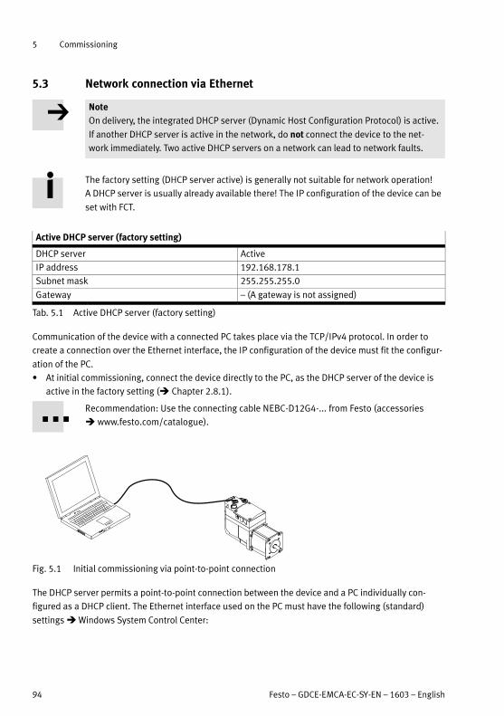
5 Commissioning
94 Festo – GDCE-EMCA-EC-SY-EN – 1603 – English
5.3 Network connection via Ethernet
Note
On delivery, the integrated DHCP server (Dynamic Host Configuration Protocol) is active.
If another DHCP server is active in the network, do not connect the device to the net
work immediately. Two active DHCP servers on a network can lead to network faults.
The factory setting (DHCP server active) is generally not suitable for network operation!
A DHCP server is usually already available there! The IP configuration of the device can be
set with FCT.
Active DHCP server (factory setting)
DHCP server Active
IP address 192.168.178.1
Subnet mask 255.255.255.0
Gateway – (A gateway is not assigned)
Tab. 5.1 Active DHCP server (factory setting)
Communication of the device with a connected PC takes place via the TCP/IPv4 protocol. In order to
create a connection over the Ethernet interface, the IP configuration of the device must fit the configur
ation of the PC.
At initial commissioning, connect the device directly to the PC, as the DHCP server of the device is
active in the factory setting ( Chapter 2.8.1).
Recommendation: Use the connecting cable NEBC-D12G4-... from Festo (accessories
www.festo.com/catalogue).
Fig. 5.1 Initial commissioning via point-to-point connection
The DHCP server permits a point-to-point connection between the device and a PC individually con
figured as a DHCP client. The Ethernet interface used on the PC must have the following (standard)
settings Windows System Control Center:
5 Commissioning
Festo – GDCE-EMCA-EC-SY-EN – 1603 – English 95
– “Automatically obtain IP address”
– “Automatically obtain DNS server address”
If the Ethernet interface of the PC is set accordingly, the DHCP server of the device assigns a suitable IP
address to the PC.
The DHPC server of the device is not intended for supplying existing networks with IP addresses.
The DHCP server issues the following IP configurations:
– IP addresses from the following range: 192.168.178.110 ... 192.168.178.209
– Subnet mask: 255.255.255.0.
– Gateway: – (a gateway is not assigned).
Create network connection – example
Prerequisite:
– The PC is configured as a DHCP client (usually the default setting for PCs).
– The EMCA is configured as a DHCP server (factory setting).
1. Connect the Ethernet interface of the EMCA directly to the Ethernet interface of the PC (point-to-
point connection).
2. Switch on the power supply of the device.
The DHCP server of the device then assigns an IP address to the PC. This establishes the network
connection.
Testing the network connection
1. Start the web browser of the PC (Internet Explorer > 6; Firefox > 3; activate JavaScript).
2. Type the IP address of the device (factory setting: 192.168.178.1) into the address bar. Then the
web site of the device appears ( Chapter 5.5).
Or:
Start FCT and establish an online connection ( FCT, command [Component] [Online] [Login]).
Actions in case of communication problems
Check the TCP/IPv4-settings of the used Ethernet interface of the PC ( Windows System Control):
– “Obtain an IP address automatically”
– “Obtain DNS server address automatically”
5.3.1 Displaying or changing network configuration
IP configuration can be carried out with FCT. FCT also offers a search function (network scan) with which
a device can be found in the network without knowledge of the current IP configuration.
Scanning network
If there is no online connection to the device yet, start network scan with FCT ( FCT, command
[Component] [FCT Interface], button “Scan...”).
The devices found are then displayed in a list.
5 Commissioning
96 Festo – GDCE-EMCA-EC-SY-EN – 1603 – English
Changing network setting
If there is no online connection:
1. Scan network and mark the found device in the list.
2. In the context menu, select the command [Network].
The current network setting is then displayed and can be changed.
3. Change network setting and confirm the change with OK.
The network setting is then displayed.
If an online connection already exists:
1. In the menu [Component], select the command [Online] [Setup Network Settings ...].
The current network setting is then displayed and can be changed.
2. Change network setting and confirm the change with OK.
The changes take immediate effect and are automatically stored in the device.
Possible network settings ( Also chapter 2.8.1)
– DHCP server active (factory setting, Tab. 5.1)
– DHCP-Client (“Obtain IP address automatically”): EMCA obtains the IP address from a DHCP server
in your network.
– Fixed IP address: A fixed IP address can be assigned to the device.
5.3.2 Security in the network
Note
Unauthorised access to the device can cause damage or malfunctions. When connect
ing the device to a network:
Protect the network from unauthorised access.
Measures for protecting the network include:
– Firewall
– Intrusion prevention system (IPS)
– Network segmentation
– Virtual LAN (VLAN)
– Virtual Private Network (VPN)
– Security at a physical access level (port security).
For additional information Guidelines and standards for security in information tech
nology, e.g. IEC 62443, ISO/IEC 27001.
Recommendation: Activate password protection to avoid accidental access to the device
( FCT, command [Component] [Online] [Password]).
Password protection
In the delivery status of the device, password protection is inactive. With FCT, password protection can
be activated through entry of a password ( FCT Help).
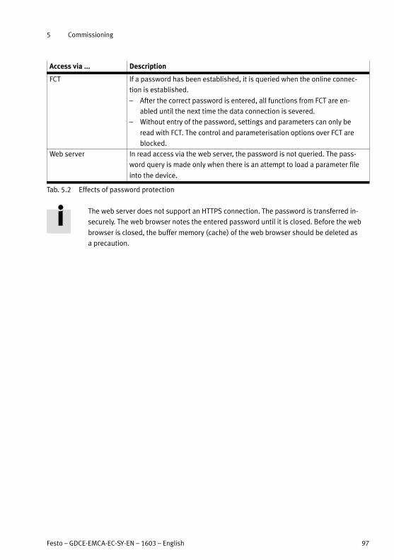
5 Commissioning
Festo – GDCE-EMCA-EC-SY-EN – 1603 – English 97
Access via ... Description
FCT If a password has been established, it is queried when the online connec
tion is established.
– After the correct password is entered, all functions from FCT are en
abled until the next time the data connection is severed.
– Without entry of the password, settings and parameters can only be
read with FCT. The control and parameterisation options over FCT are
blocked.
Web server In read access via the web server, the password is not queried. The pass
word query is made only when there is an attempt to load a parameter file
into the device.
Tab. 5.2 Effects of password protection
The web server does not support an HTTPS connection. The password is transferred in
securely. The web browser notes the entered password until it is closed. Before the web
browser is closed, the buffer memory (cache) of the web browser should be deleted as
a precaution.

5 Commissioning
98 Festo – GDCE-EMCA-EC-SY-EN – 1603 – English
5.4 Master control
Master control determines through which interface the device may be controlled. The device cannot be
controlled over several interfaces simultaneously. The following interfaces can receive master control:
– Control interface (for control in operation)
– Parameterisation interface (for commissioning and diagnostics)
Simultaneous connections
Several connections simultaneously are technically possible via the parameterisation interface, e.g.
over several web browsers or FCTs. If master control has been transferred to the parameterisation inter
face, parameterisation and control are possible only over the first connection. All other connections
have only read rights (for diagnostics). Changeover is possible in enabled as well as in non-enabled
status. That means, the device does not prevent changeover of master control during an active move
ment.
Recommendation: Before the changeover of master control, a stop command should be
sent through the interface with master control.
The enable signal of the interface that currently has master control is always valid. If, for example, the
FCT switches over to the control interface, the enable signal of the control interface applies from the
switchover time on.
Active and passive connections through parameterisation interface
A maximum of 3 simultaneous connections with the device are permitted over the parameterisation
interface:
– 2 connections over FCT
– 1 connection over web server
If 2 connections are created over FCT, the first connection made is the active one. The second connec
tion is passive. A passive connection cannot become an active connection. For that, both connections
would first have to be terminated, then rebuilt in the desired sequence.
Connections Rights
Active connection Write rights for parameterisation, control, transfer of master control and
read rights
Passive connection Read rights for diagnostics
Tab. 5.3 Connections and rights via Ethernet interface
A web server connection can always be built up. If FCT does not have master control, the web server
connection can take over master control to load a parameter file.

5 Commissioning
Festo – GDCE-EMCA-EC-SY-EN – 1603 – English 99
Switching over master control
After the device is switched on, the control interface always has master control. The active FCT connec
tion can take over master control from the control interface if the control interface does not block it.
Changeover is possible in enabled as well as in non-enabled status. Master control can also be taken
over during execution of an order. For this, an ongoing order is stopped (Quick Stop).
Connection Switching over master control
FCT Can take over master control from all other connections (Device Control: activate FCT).
When the device control is deactivated, master control is restored to the control interface.
Web server To transfer the parameter file, the web server can take over master control from the
control interface. When the procedure is ended, master control is restored to the
control interface.
Tab. 5.4 Changeover of device control
To remove master control from the control interface and transfer it to FCT:
In the online tab “Operate” under “Device Control”, activate the “FCT” checkbox.
For the FCT to control the connected device, the “Enable” checkbox must be activated after takeover of
master control.
If master control is released again by FCT, it automatically goes back to the control interface.
Blocking switchover of master control (only over FHPP)
Switchover of master control can be blocked over the active control interface. Switchover from the
control interface to the parameterisation interface is possibly only after the block is released.
Time-out
When FCT has master control, the device detects when the connection to the FCT software has been
interrupted. The device then behaves as parameterised in FCT on the page “Error Management”
(malfunction number 0x32). The time-out time is typically 1 s. For slow networks, a longer time-out time
can be selected.

5 Commissioning
100 Festo – GDCE-EMCA-EC-SY-EN – 1603 – English
5.5 Online connection with the web server
Requirements for call-up of the web server
– The power supply of the device is switched on.
– The IP configuration of the device is correctly set ( Chapter 2.8.1, Tab. 2.46).
– Device and PC are connected via the Ethernet interface (direct connection or connection over
a network).
IP address of the device
In the factory setting, the device has the following IP address: 192.168.178.1.
If the IP configuration of the device has been changed, the current IP address can be determined with
FCT ( FCT, command [Component] [FCT Interface], button “Scan...”).
Call the web server
1. Open Internet browser, e.g. Internet Explorer version 6 or later or Firefox version 3 or later.
2. Enter the IP address of the device in the address line of the Internet browser.
Then the web site of the device appears.
Fig. 5.2 Website of the web server
Active signals are marked with a blue dot. Inactive signals are marked with a grey dot.
Sections of the website Description
Status
(Status)
Shows status information about the device
Basic I/O interface:
(Basic I/O Interface)
Shows signal statuses of the digital basic I/Os
FHPP interface
(FHPP Interface)
Shows signal statuses of the I/O data of the FHPP protocol

5 Commissioning
Festo – GDCE-EMCA-EC-SY-EN – 1603 – English 101
Sections of the website Description
Upload/download parameters
(Parameter Up-/Download)
Permits uploading and downloading of a parameter file
( Chapter 5.7)
Diagnostic memory
(Diagnostic Memory)
Permits read-out and display of the diagnostic memory
( Chapter 6.1)
Tab. 5.5 Sections of the website of the web server

5 Commissioning
102 Festo – GDCE-EMCA-EC-SY-EN – 1603 – English
5.6 Commissioning steps
Overview
Preparations for commissioning
1. Check mounting of the axis assembly and seal inserts as well as cable throughfeeds ( Chapter 3).
2. Check setting of the DIP switch for the terminating resistor ( Description for the respective device
profile).
3. Check wiring of the device ( Chapter 4).
4. Create FCT project ( Help for the EMCA plug-in).
5. Establish connection with the PC and set network configuration ( Chapter 5.3).
The following steps must be performed in the initial commissioning:
1. Perform configuration and parameterisation with the FCT software (hardware configuration, limit
values and parameters) ( Chapter 5.6.1 as well as Help for the EMCA plug-in)
2. With use of safety function STO: check the STO function ( Documentation GDCE-EMCA-EC-S1-...)
3. Check signal characteristics of the digital I/O (e.g. limit/reference switch).
4. Provide required control signals ( Chapter 5.6.4).
5. Check direction of rotation/direction of travel of the electromechanical drive (e.g. in jog operation).
If required, activate reversing of rotation to reverse the direction ( FCT, command [Application
Data], [Environment], “Inverse Rotation Polarity”).
6. Perform homing ( Chapter 2.4.2).
7. Test positioning behaviour (test mode Help for the EMCA plug-in).
8. Optimise controller setting (optional, Help for the EMCA plug-in).
9. Perform fieldbus configuration and test control profile ( Description for the device profile used).
10. Complete commissioning ( Help for the EMCA plug-in).
5.6.1 Configuration and parameterisation
Perform configuration and parameterisation conscientiously.
Do not operate the device with unknown settings.
– If the system structure consists of Festo components, parameters and limit values are preset by the
plug-in.
– If the system structure contains user-specific components, parameters and limit values must be
determined based on the system structure. For example, the maximum motor current can be limited
so the permissible load of a system component is not exceeded.
– Application-related parameters and limit values must be determined based on the application.
For detailed information on parameterisation and optimisation of the controller setting
Plug-in Help of the FCT.
5 Commissioning
Festo – GDCE-EMCA-EC-SY-EN – 1603 – English 103
Load parameter file
If a parameter file (*.fpf ) is available for the project, the following options exist:
– The parameter file can be downloaded with the web server directly into the device ( Chapter 5.7).
– The parameter file can be imported into an FCT project and downloaded into the device ( FCT Help).
5.6.2 Checking STO function
With use of the safety function STO [X6]:
The safety function STO must be validated before commissioning (in accordance with EC Machinery
Directive).
For additional information on intended use of the safety function “Safe torque off/STO”
Description GDCE-EMCA-EC-S1-...
5.6.3 Check signal characteristics of the limit and reference switch
Check connection and mounting of the limit and reference switches.
If limit switches are to offer a certain protection against travel to mechanical stops or end positions,
they must become effective at sufficient distance from the stops or end positions (through correspond
ing switching ranges or suitable design measures).
To avoid homing errors, there must no range between the limit switch and the nearest
stop or end position in which the limit switch is not actuated (undefined range).
Ferritic elements in the vicinity of magnetic switches can influence the switching range
(e.g. mounting components).
With FCT, the inputs for limit and reference switches must be activated and the switch type used correctly
configured ( FCT, page “Axis”, tab “Axis Options”).
5.6.4 Providing required signals (digital I/Os)
For commissioning and operation, the device needs the following signals through the I/O interface and
STO interface:
– STO interface (2-channel): Signals STO 1 and STO 2 Description safety function STO,
GDCE-EMCA-EC-S1-...
– I/O interface: signal Control enable

5 Commissioning
104 Festo – GDCE-EMCA-EC-SY-EN – 1603 – English
5
4
24 V DC
STO 2
STO 1
Control enable (DIN)
[X6]
configurable (DOUT)2)
Ready (DOUT)
4
1
2
[X9]1)
Description
GDCE-EMCA-EC-S1-...
EMCA
1) Switch setting with switched-on controller enable
2) Optional; output in the Festo Configuration Tool (FCT) freely configurable (e.g. “common error”)
Fig. 5.3 Connection: digital inputs/outputs for operation
5.6.5 Checking direction of rotation/travel direction
In the online register “Manual Move”, FCT offers access to jog operation. With jogging, the motor can be
moved manually to visually check the direction of rotation. Homing is not required for this ( FCT Help).
Prerequisites are:
– STO function is not requested.
– Enable signal is present at the “Control enable” input.
– Online connection with the EMCA is established.
– FCT has master control ( FCT, “Device Control”, “FCT”).
– The drive is enabled ( FCT, “Device Control”, “Enable”).
Carefully check direction of rotation with jogging (Observe drive).
If required, reverse direction of rotation with the “Reverse direction of rotation” parameter
( FCT, page “Application Data”, tab “Environment”, “Inverse Rotation Polarity”).

5 Commissioning
Festo – GDCE-EMCA-EC-SY-EN – 1603 – English 105
5.6.6 Carrying out homing
Recommendations for parameterisation
Do not change default settings, if possible. If changes are required:
– Select low search/crawl speed to enable the target points to be identified as ac
curately as possible.
– Set deceleration high enough to prevent the target points from being overrun dur
ing the search run.
In the online register “Homing”, FCT offers access to the Homing drive function.
Prerequisites are:
– STO function is not requested.
– Enable signal is present at the “Control enable” input.
– Online connection with the EMCA is established.
– FCT has master control ( FCT, “Device Control”, “FCT”).
– The drive is enabled ( FCT, “Device Control”, “Enable”).
Of course, homing can also be executed through FHPP or CiA402.
For additional information Description for the device profile.
5.6.7 Testing positioning behaviour (test mode)
Through manual movement with FCT, it can be determined whether the device is fundamentally ready
for operation. In addition, the settings of the measuring reference system and the software end posi
tions can be checked.
FCT makes it possible to record drive data over a defined period in real time, e.g. speeds and contouring
errors during a movement.
For additional information on this Help on the EMCA plug-in.
5.6.8 Optimising controller setting (optional)
When using Festo components:
– The controller parameters are calculated by the FCT plug-in and preset.
When using user-specific components or if the control behaviour should be further optimised:
Optimise controller settings as described in the Help for the EMCA plug-in ( Help for the EMCA
plug-in).
5.6.9 Performing fieldbus configuration and testing control profile
For information on this Description for the device profile and Help for the EMCA plug-in.
5 Commissioning
106 Festo – GDCE-EMCA-EC-SY-EN – 1603 – English
5.6.10 Completing commissioning
Note
Loss of device data
If the power supply is interrupted, any modifications made to the device data that have
not been saved to the permanent memory will be lost.
Save each change to the device data in the permanent memory of the device
(FCT: Store).
When downloading (Download) parameters with FCT, the data are stored only temporarily in the device.
The temporarily stored data are lost when the power supply is switched off.
To conclude commissioning:
Recommendation: Activate password protection ( Help for the EMCA plug-in).
Save parameters permanently in the device ( Help for the EMCA plug-in).
Recommendation: Save parameters of the device in a parameter file ( Chapter 5.7).
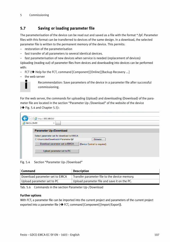
5 Commissioning
Festo – GDCE-EMCA-EC-SY-EN – 1603 – English 107
5.7 Saving or loading parameter file
The parameterisation of the device can be read out and saved as a file with the format *.fpf. Parameter
files with this format can be transferred to devices of the same design. In a download, the selected
parameter file is written to the permanent memory of the device. This permits:
– restoration of the parameterisation
– fast transfer of all parameters to several identical devices.
– fast parameterisation of new devices when service is needed (replacement of devices)
Uploading (reading out) of parameter files from devices and downloading into devices can be performed
with:
– FCT ( Help for the FCT, command [Component] [Online] [Backup Recovery ...]
– the web server
Recommendation: Save parameters of the device in a parameter file after successful
commissioning.
For the web server, the commands for uploading (Upload) and downloading (Download) of the para
meter file are located in the section “Parameter Up-/Download” of the website of the device
( Fig. 5.4 and Chapter 5.5):
Fig. 5.4 Section “Parameter Up-/Download”
Command Description
Download parameter set to EMCA Transfer parameter file to the device memory.
Upload parameter set to PC Upload parameter file and save it on the PC.
Tab. 5.6 Commands in the section Parameter Up-/Download
Further options
With FCT, a parameter file can be imported into the current project and parameters of the current project
exported into a parameter file ( FCT, command [Component] [Import/Export]).

5 Commissioning
108 Festo – GDCE-EMCA-EC-SY-EN – 1603 – English
5.8 Notes for operation
Control of the device is via the control interface over CANopen with the device profile FHPP or CiA 402.
Depending on the selected device profile, various drive functions are available.
For additional information Description for the respective device profile:
– Description of device profile FHPP, GDCE-EMCA-EC-HP-...
– Description of device profile CiA 402, GDCE-EMCA-EC-CO-...
5.8.1 Maximum writing cycles of the flash memory
Stored in the integrated flash memory are parameter files, for example. In addition, firmware updates
are stored in the flash memory. In principle, the number of possible write cycles is limited. The FLASH
memory is designed for 100,000 write cycles.
With the following procedures, entries are written to the flash memory:
– Download of a new parameter file
– Firmware update
– “Store” in FCT
– Store data via fieldbus
– Configuration of fault characteristics/error responses
– Recording of movements with the trace function in FCT

6 Diagnostics and fault clearance
Festo – GDCE-EMCA-EC-SY-EN – 1603 – English 109
6 Diagnostics and fault clearance
For information on classification of diagnostic messages of the device and parameterisa
tion of possible error responses Chapter 2.7.4 and FCT Help, keyword “Error Manage
ment”.
When an error occurs, the device goes into error status. The output “Ready” is hereby reset to “Low”.
Acknowledge error
Some errors can be acknowledged immediately, e.g. a following error. For other errors, the cause of the
error must be remedied first, e.g. temperature error, load voltage error. For some errors, a restart of the
device is necessary, e.g. encoder errors.
For error-specific information on readiness for acknowledgment List of diagnostic messages in
Chapter 6.3.2.
Acknowledgeable error messages can be acknowledged as follows:
– Festo Configuration Tool ( FCT online Help)
– Fieldbus ( Description for the device profile used)
If errors cannot be acknowledged, the device must be switched on again (power OFF/ON).
Diagnostic events that are parameterised as warnings are displayed once and do not
need to be acknowledged.
6.1 Access to the diagnostic memory
The diagnostic memory of the device ( Chapter 2.7.5) can be accessed as follows:
Access via Options
FCT In online mode, the diagnostic memory can be read out, displayed, deleted or
exported ( Help on FCT – online register “Diagnosis”).
Fieldbus Read out diagnostic memory entries ( Description of device profile).
Web server1) Read out and display diagnostic memory.
1) For information on the web server Chapter 5.5.
Tab. 6.1 Access to the diagnostic memory
The web server of the device displays the section “Diagnostic Memory” (diagnostic memory) as the last
section of the English-language website. The most recent diagnostic message is displayed in the top row.
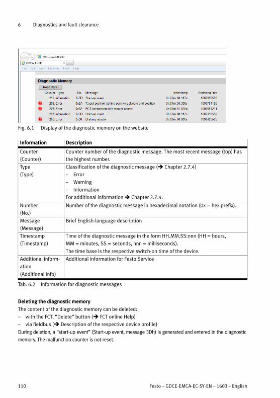
6 Diagnostics and fault clearance
110 Festo – GDCE-EMCA-EC-SY-EN – 1603 – English
Fig. 6.1 Display of the diagnostic memory on the website
Information Description
Counter
(Counter)
Counter number of the diagnostic message. The most recent message (top) has
the highest number.
Type
(Type)
Classification of the diagnostic message ( Chapter 2.7.4)
– Error
– Warning
– Information
For additional information Chapter 2.7.4.
Number
(No.)
Number of the diagnostic message in hexadecimal notation (0x = hex prefix).
Message
(Message)
Brief English-language description
Timestamp
(Timestamp)
Time of the diagnostic message in the form HH.MM.SS:nnn (HH = hours,
MM = minutes, SS = seconds, nnn = milliseconds).
The time base is the respective switch-on time of the device.
Additional inform
ation
(Additional Info)
Additional information for Festo Service
Tab. 6.2 Information for diagnostic messages
Deleting the diagnostic memory
The content of the diagnostic memory can be deleted:
– with the FCT, “Delete” button ( FCT online Help)
– via fieldbus ( Description of the respective device profile)
During deletion, a “start-up event” (Start-up event, message 3Dh) is generated and entered in the diagnostic
memory. The malfunction counter is not reset.

6 Diagnostics and fault clearance
Festo – GDCE-EMCA-EC-SY-EN – 1603 – English 111
6.2 Diagnostics via LED
EMCA-EC-...-CO (CANopen)
1
2
3
1 LED OK
2 LED ERROR
3 LED bus status (bi-colour)1)
1) Bus-specific LED (CANopen)
Fig. 6.2 LED of the device (example EMCA-EC-...-CO)
Information on the bus-specific LED (bus status LED) Description of the device profile used (FHPP or
CiA 402).
6.2.1 Behaviour in the switch-on phase
LED LED status Event/status
OK Flashes green – Start-up phase, bootloader active
ERROR Flashes red
Tab. 6.3 Behaviour in the switch-on phase
6.2.2 Behaviour in the operating phase
LED LED status Event/status
OK Off – Hardware is not ready for operation; an error is present.
Flashes green – Hardware is ready for operation, but the signal “Control enable” is not
present.
Green – Normal operating status; hardware is ready for operation; signal “Control
enable” is present
ERROR Off – No error, no warning
Flashes red – A warning is signaled.
Red – An error is reported.
Tab. 6.4 Behaviour in the operating phase

6 Diagnostics and fault clearance
112 Festo – GDCE-EMCA-EC-SY-EN – 1603 – English
6.2.3 Behaviour during waving
LED LED status Event/status
OK Flashing at
the same
time
Waving function active (for optical identification, can be activated via the
webserver)ERROR
Tab. 6.5 Behaviour during waving
6.2.4 Behaviour with errors in the firmware update phase
LED LED status Event/status
OK Off Firmware update was cancelled due to an error.
ERROR Flashes red1)
1) The dark phase is 10 times as long as the switch-on phase.
Tab. 6.6 Behaviour during a firmware update
Actions in the event of an error
Switch device off and back on.
Restart the firmware download process.
If the error occurs repeatedly, contact your local Festo Service.
6.2.5 Bus-specific LED
EMCA-EC-...-CO (CANopen)
The two-colour bus-status LED (green/red) signals the bus status.
Detailed information on the bus status LED Description of the respective device profile:
– Description of device profile FHPP, GDCE-EMCA-EC-HP-...
– Description of device profile CiA 402, GDCE-EMCA-EC-CO-...
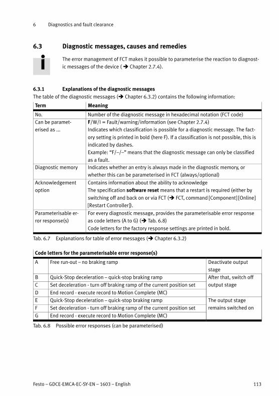
6 Diagnostics and fault clearance
Festo – GDCE-EMCA-EC-SY-EN – 1603 – English 113
6.3 Diagnostic messages, causes and remedies
The error management of FCT makes it possible to parameterise the reaction to diagnost
ic messages of the device ( Chapter 2.7.4).
6.3.1 Explanations of the diagnostic messages
The table of the diagnostic messages ( Chapter 6.3.2) contains the following information:
Term Meaning
No. Number of the diagnostic message in hexadecimal notation (FCT code)
Can be paramet
erised as ...
F/W/I = Fault/warning/information (see Chapter 2.7.4)
Indicates which classification is possible for a diagnostic message. The fact
ory setting is printed in bold (here F). If a classification is not possible, this is
indicated by dashes.
Example: “F/–/–” means that the diagnostic message can only be classified
as a fault.
Diagnostic memory Indicates whether an entry is always made in the diagnostic memory, or
whether this can be parameterised in FCT (always/optional)
Acknowledgement
option
Contains information about the ability to acknowledge
The specification software reset means that a restart is required (either by
switching off and back on or via FCT ( FCT, command [Component] [Online]
[Restart Controller]).
Parameterisable er
ror response(s)
For every diagnostic message, provides the parameterisable error response
as code letters (A to G) ( Tab. 6.8)
Code letters for the factory response settings are printed in bold.
Tab. 6.7 Explanations for table of error messages ( Chapter 6.3.2)
Code letters for the parameterisable error response(s)
A Free run-out – no braking ramp Deactivate output
stage
B Quick-Stop deceleration – quick-stop braking ramp After that, switch off
output stageC Set deceleration - turn off braking ramp of the current position set
D End record - execute record to Motion Complete (MC)
E Quick-Stop deceleration – quick-stop braking ramp The output stage
remains switched onF Set deceleration - turn off braking ramp of the current position set
G End record - execute record to Motion Complete (MC)
Tab. 6.8 Possible error responses (can be parameterised)
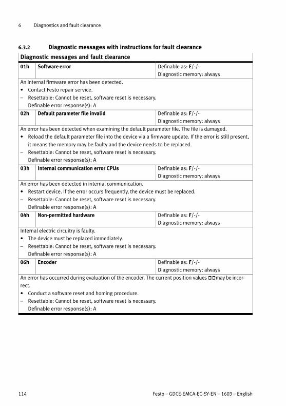
6 Diagnostics and fault clearance
114 Festo – GDCE-EMCA-EC-SY-EN – 1603 – English
6.3.2 Diagnostic messages with instructions for fault clearance
Diagnostic messages and fault clearance
01h Software error Definable as: F/-/-
Diagnostic memory: always
An internal firmware error has been detected.
Contact Festo repair service.
– Resettable: Cannot be reset, software reset is necessary.
Definable error response(s): A
02h Default parameter file invalid Definable as: F/-/-
Diagnostic memory: always
An error has been detected when examining the default parameter file. The file is damaged.
Reload the default parameter file into the device via a firmware update. If the error is still present,
it means the memory may be faulty and the device needs to be replaced.
– Resettable: Cannot be reset, software reset is necessary.
Definable error response(s): A
03h Internal communication error CPUs Definable as: F/-/-
Diagnostic memory: always
An error has been detected in internal communication.
Restart device. If the error occurs frequently, the device must be replaced.
– Resettable: Cannot be reset, software reset is necessary.
Definable error response(s): A
04h Non-permitted hardware Definable as: F/-/-
Diagnostic memory: always
Internal electric circuitry is faulty.
The device must be replaced immediately.
– Resettable: Cannot be reset, software reset is necessary.
Definable error response(s): A
06h Encoder Definable as: F/-/-
Diagnostic memory: always
An error has occurred during evaluation of the encoder. The current position values may be incor
rect.
Conduct a software reset and homing procedure.
– Resettable: Cannot be reset, software reset is necessary.
Definable error response(s): A

6 Diagnostics and fault clearance
Festo – GDCE-EMCA-EC-SY-EN – 1603 – English 115
Diagnostic messages and fault clearance
07h Limit switch positive Definable as: F/-/-
Diagnostic memory: optional
The drive is at the positive limit switch.
Acknowledge error and move the drive in a negative direction to the permissible range. Also check
the movement range and record parameters, if necessary.
Check switches and cables.
Check positioning dynamics (overshoot?), e.g. with trace diagrams in FCT.
– Resettable: Error can be reset immediately.
Definable error response(s): A, B, C, E, F
08h Limit switch negative Definable as: F/-/-
Diagnostic memory: optional
The drive is at the negative limit switch.
Reset error and move the drive in a positive direction into the permissible range. Also check the
movement range and record parameters, if necessary.
Check switches and cables.
Check positioning dynamics (overshoot?), e.g. with trace diagrams in FCT.
– Resettable: Error can be reset immediately.
Definable error response(s): A, B, C, E, F
09h Offset determination for current measurement Definable as: F/-/-
Diagnostic memory: always
An error has occurred during initialisation of the current measurement.
Perform a software reset.
– Resettable: Cannot be reset, software reset is necessary.
Definable error response(s): A
0Bh Parameter file invalid Definable as: F/-/-
Diagnostic memory: always
No valid parameter set stored. After creation of the parameter file, a firmware update is performed,
if necessary: As much data as possible is automatically loaded from the parameter file. Parameters
that are not initialised by the parameter file are loaded from the default parameter file.
Enter a valid parameter set in the device. If the error is still present, the hardware may be defective.
– Resettable: Error can be reset immediately.
Definable error response(s): A

6 Diagnostics and fault clearance
116 Festo – GDCE-EMCA-EC-SY-EN – 1603 – English
Diagnostic messages and fault clearance
0Ch Firmware update execution error Definable as: F/-/-
Diagnostic memory: optional
The firmware update has not been properly executed or completed.
Check Ethernet connection between device and PC. Restart device and perform the firmware up
date again. Check whether valid firmware has been selected for the device. The previous firmware
version remains active until the firmware update has been successfully completed. If this error is
still present, the hardware may be defective.
– Resettable: Cannot be reset, software reset is necessary.
Definable error response(s): A
0Dh Overcurrent Definable as: F/-/-
Diagnostic memory: always
Short circuit in the motor, lines or brake chopper.
Output stage defective.
Incorrect parameterisation of the current regulator.
Check parameterisation of the current regulator. An incorrectly parameterised current regulator
can generate currents up to the short-circuit limit; as a rule this is clearly noticeable through high
frequency whistling. Inspection with the trace function in FCT (active current actual value).
Error message immediately after connecting to the load supply: Short circuit in the output stage.
The device must be replaced immediately.
Error message only occurs when setting the output stage enable: Short circuit in motor or the
(internal) motor cables. Replace device.
Error occurs only with active brake chopper: Check external braking resistor for short circuit or
insufficient resistance value.
– Resettable: Cannot be reset, software reset is necessary.
Definable error response(s): A
0Eh I²t malfunction motor Definable as: F/-/-
Diagnostic memory: always
The I²t limit for the motor is reached. The motor or the drive system may be insufficient for the required
task.
Check the layout of the drive system.
Check the mechanical system for sluggishness.
Reduce load/dynamic response, longer time delays.
– Resettable: Error can only be reset after the cause of the error has been eliminated.
Definable error response(s): B, C

6 Diagnostics and fault clearance
Festo – GDCE-EMCA-EC-SY-EN – 1603 – English 117
Diagnostic messages and fault clearance
11h Software limit positive Definable as: F/-/-
Diagnostic memory: optional
The position setpoint has reached or exceeded the respective software end position.
Check target data.
Check positioning area.
This error can be reset immediately. Afterwards start a corresponding positioning record or move
the drive by using the jogging function. Movements in a positive direction are blocked.
– Resettable: Error can be reset immediately.
Definable error response(s): A, B, C, E, F
12h Software limit negative Definable as: F/-/-
Diagnostic memory: optional
The position setpoint has reached or exceeded the respective software end position.
Check target data.
Check positioning area.
This error can be reset immediately. Afterwards start a corresponding positioning record or move
the drive by using the jogging function. Movements in a negative direction are blocked.
– Resettable: Error can be reset immediately.
Definable error response(s): A, B, C, E, F
13h Positive direction locked Definable as: F/-/-
Diagnostic memory: optional
A limit switch error or a software limit position error has occurred and subsequent positioning
in the blocked direction has been initiated.
Check target data.
Check positioning area.
This error can be reset immediately. Afterwards start a corresponding positioning record or move
the drive by using the jogging function. Movements in a positive direction are blocked.
– Resettable: Error can be reset immediately.
Definable error response(s): A, B, C, E, F
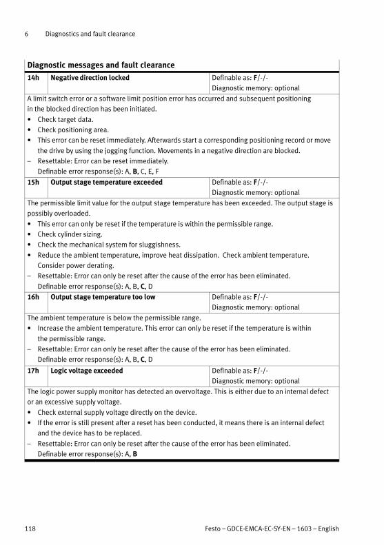
6 Diagnostics and fault clearance
118 Festo – GDCE-EMCA-EC-SY-EN – 1603 – English
Diagnostic messages and fault clearance
14h Negative direction locked Definable as: F/-/-
Diagnostic memory: optional
A limit switch error or a software limit position error has occurred and subsequent positioning
in the blocked direction has been initiated.
Check target data.
Check positioning area.
This error can be reset immediately. Afterwards start a corresponding positioning record or move
the drive by using the jogging function. Movements in a negative direction are blocked.
– Resettable: Error can be reset immediately.
Definable error response(s): A, B, C, E, F
15h Output stage temperature exceeded Definable as: F/-/-
Diagnostic memory: optional
The permissible limit value for the output stage temperature has been exceeded. The output stage is
possibly overloaded.
This error can only be reset if the temperature is within the permissible range.
Check cylinder sizing.
Check the mechanical system for sluggishness.
Reduce the ambient temperature, improve heat dissipation. Check ambient temperature.
Consider power derating.
– Resettable: Error can only be reset after the cause of the error has been eliminated.
Definable error response(s): A, B, C, D
16h Output stage temperature too low Definable as: F/-/-
Diagnostic memory: optional
The ambient temperature is below the permissible range.
Increase the ambient temperature. This error can only be reset if the temperature is within
the permissible range.
– Resettable: Error can only be reset after the cause of the error has been eliminated.
Definable error response(s): A, B, C, D
17h Logic voltage exceeded Definable as: F/-/-
Diagnostic memory: optional
The logic power supply monitor has detected an overvoltage. This is either due to an internal defect
or an excessive supply voltage.
Check external supply voltage directly on the device.
If the error is still present after a reset has been conducted, it means there is an internal defect
and the device has to be replaced.
– Resettable: Error can only be reset after the cause of the error has been eliminated.
Definable error response(s): A, B

6 Diagnostics and fault clearance
Festo – GDCE-EMCA-EC-SY-EN – 1603 – English 119
Diagnostic messages and fault clearance
18h Logic voltage too low Definable as: F/-/-
Diagnostic memory: optional
The logic power supply monitor has detected an undervoltage. There is either an internal defect or an
overload/short circuit caused by connected peripherals.
Separate device from the entire peripheral equipment and check whether the error is still present
after reset. If it is, it means there is an internal defect and the device has to be replaced.
– Resettable: Cannot be reset, software reset is necessary.
Definable error response(s): A
19h Real time error LM-CPU Definable as: F/-/-
Diagnostic memory: optional
The LM-CPU requires more computation time than is available to it.
Check whether multiple connections have been established to the device. If yes, terminate the
unneeded connections. Further remedial measures: Do without trace drawings, reduce bus load
– Resettable: Error can be reset immediately.
Definable error response(s): A, B
1Ah Intermediate circuit voltage exceeded Definable as: F/-/-
Diagnostic memory: always
Load voltage not within the permissible range.
Braking resistor is overloaded; too much braking energy which cannot be dissipated quickly enough.
Braking resistor is defective or not connected.
Check power supply; measure voltage directly at the device.
Check the design of the external braking resistor. The resistance value is possibly too large.
Check the connection to the braking resistor.
– Resettable: Error can only be reset after the cause of the error has been eliminated.
Definable error response(s): A, B
1Bh Intermediate circuit voltage too low Definable as: F/W/-
Diagnostic memory: optional
The load voltage is too low.
Voltage drops under load: power supply unit too weak, supply line too long, cross section too
small?
If you intentionally want to operate the device with a lower voltage, parameterise this malfunction
as a warning.
– If parameterised as an error: The error can only be reset after the cause is eliminated.
Definable error response(s): A
– If parameterised as a warning: The warning disappears if the load voltage is back within the per
missible range.

6 Diagnostics and fault clearance
120 Festo – GDCE-EMCA-EC-SY-EN – 1603 – English
Diagnostic messages and fault clearance
1Ch CAN Node Guarding, FB has master control Definable as: F/-/-
Diagnostic memory: optional
No node monitoring telegram received within the parameterised time.
Adjust the remote frame cycle time to the PLC and check the PLC for failure.
Check cabling: cable specification adhered to, cable break, maximum cable length exceeded,
correct terminating resistors, cable screening grounded, all wires connected? Replace the device
to test the setup. If another device works flawlessly with the same wiring, it means the device is
defective.
– Resettable: Error can only be reset after the cause of the error has been eliminated.
Definable error response(s): B, C, E, F
1Dh CAN bus comm. stopped by master, FB has master
control
Definable as: F/-/-
Diagnostic memory: optional
The master has stopped CAN-bus communication.
Check master.
– Resettable: Error can only be reset after the cause of the error has been eliminated.
Definable error response(s): B, C, E, F
20h FHPP+ incorrect parameterisation Definable as: F/W/-
Diagnostic memory: optional
Parameterisation of the FHPP+ telegram entries is faulty. The PNU may not be present on the device
or a 16-bit value has been mapped to an odd address.
Check entries in the telegram editor. An overview of the PNUs available in the device and their size
can be found in the FHPP documentation of your device.
– If parameterised as an error: The error can only be reset after the cause is eliminated.
Definable error response(s): B, C, E, F, G
– If parameterised as a warning: The warning disappears when a valid telegram entry is written.
21h FHPP+ incorrect value Definable as: F/W/I
Diagnostic memory: optional
At least one PNU has been assigned an invalid value. The telegram has been ignored.
Correct the values and send the telegram again.
– If parameterised as an error: Error can be reset immediately.
Definable error response(s): B, C, D, E, F, G
– If parameterised as a warning: The warning disappears when a valid telegram is received.
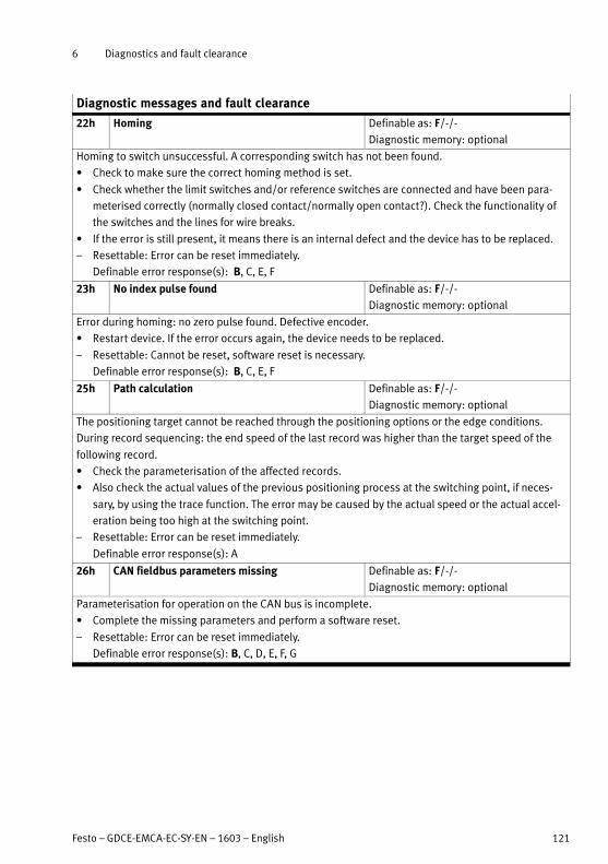
6 Diagnostics and fault clearance
Festo – GDCE-EMCA-EC-SY-EN – 1603 – English 121
Diagnostic messages and fault clearance
22h Homing Definable as: F/-/-
Diagnostic memory: optional
Homing to switch unsuccessful. A corresponding switch has not been found.
Check to make sure the correct homing method is set.
Check whether the limit switches and/or reference switches are connected and have been para
meterised correctly (normally closed contact/normally open contact?). Check the functionality of
the switches and the lines for wire breaks.
If the error is still present, it means there is an internal defect and the device has to be replaced.
– Resettable: Error can be reset immediately.
Definable error response(s): B, C, E, F
23h No index pulse found Definable as: F/-/-
Diagnostic memory: optional
Error during homing: no zero pulse found. Defective encoder.
Restart device. If the error occurs again, the device needs to be replaced.
– Resettable: Cannot be reset, software reset is necessary.
Definable error response(s): B, C, E, F
25h Path calculation Definable as: F/-/-
Diagnostic memory: optional
The positioning target cannot be reached through the positioning options or the edge conditions.
During record sequencing: the end speed of the last record was higher than the target speed of the
following record.
Check the parameterisation of the affected records.
Also check the actual values of the previous positioning process at the switching point, if neces
sary, by using the trace function. The error may be caused by the actual speed or the actual accel
eration being too high at the switching point.
– Resettable: Error can be reset immediately.
Definable error response(s): A
26h CAN fieldbus parameters missing Definable as: F/-/-
Diagnostic memory: optional
Parameterisation for operation on the CAN bus is incomplete.
Complete the missing parameters and perform a software reset.
– Resettable: Error can be reset immediately.
Definable error response(s): B, C, D, E, F, G
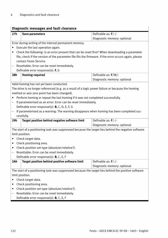
6 Diagnostics and fault clearance
122 Festo – GDCE-EMCA-EC-SY-EN – 1603 – English
Diagnostic messages and fault clearance
27h Save parameters Definable as: F/-/-
Diagnostic memory: optional
Error during writing of the internal permanent memory.
Execute the last operation again.
Check the following: Is an error present that can be reset first? When downloading a parameter
file, check if the version of the parameter file fits the firmware. If the error occurs again, please
contact Festo Service.
– Resettable: Error can be reset immediately.
Definable error response(s): F, G
28h Homing required Definable as: F/W/-
Diagnostic memory: optional
Valid homing has not yet been conducted.
The drive is no longer referenced (e.g. as a result of a logic power failure or because the homing
method or axis zero point has been changed).
Perform homing or repeat the last homing if it was not completed successfully.
– If parameterised as an error: Error can be reset immediately.
Definable error response(s): B, C, D, E, F, G
– If parameterised as a warning: The warning disappears when homing has been completed suc
cessfully.
29h Target position behind negative software limit Definable as: F/-/-
Diagnostic memory: optional
The start of a positioning task was suppressed because the target lies behind the negative software
limit position.
Check target data.
Check positioning area.
Check position set type (absolute/relative?).
– Resettable: Error can be reset immediately.
Definable error response(s): B, C, E, F
2Ah Target position behind positive software limit Definable as: F/-/-
Diagnostic memory: optional
The start of a positioning task was suppressed because the target lies behind the positive software
limit position.
Check target data.
Check positioning area.
Check position set type (absolute/relative?).
– Resettable: Error can be reset immediately.
Definable error response(s): B, C, E, F
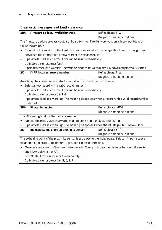
6 Diagnostics and fault clearance
Festo – GDCE-EMCA-EC-SY-EN – 1603 – English 123
Diagnostic messages and fault clearance
2Bh Firmware update, invalid firmware Definable as: F/W/-
Diagnostic memory: optional
The firmware update process could not be performed. The firmware version is incompatible with
the hardware used.
Determine the version of the hardware. You can ascertain the compatible firmware designs and
download the appropriate firmware from the Festo website.
– If parameterised as an error: Error can be reset immediately.
Definable error response(s): A
– If parameterised as a warning: The warning disappears when a new FW download process is started.
2Ch FHPP incorrect record number Definable as: F/W/I
Diagnostic memory: optional
An attempt has been made to start a record with an invalid record number.
Select a new record with a valid record number.
– If parameterised as an error: Error can be reset immediately.
Definable error response(s): F, G
– If parameterised as a warning: The warning disappears when a record with a valid record number
is started.
2Dh I²t warning motor Definable as: -/W/I
Diagnostic memory: optional
The I²t warning limit for the motor is reached.
Parameterise message as a warning or suppress completely as information.
– If parameterised as a warning: The warning disappears when the I²t integral falls below 80 %.
2Eh Index pulse too close on proximity sensor Definable as: F/-/-
Diagnostic memory: optional
The switching point of the proximity sensor is too close to the index pulse. This can in some cases
mean that no reproducible reference position can be determined.
Move reference switch/limit switch to the axis. You can display the distance between the switch
and index pulse in the FCT.
– Resettable: Error can be reset immediately.
Definable error response(s): B, C, E, F

6 Diagnostics and fault clearance
124 Festo – GDCE-EMCA-EC-SY-EN – 1603 – English
Diagnostic messages and fault clearance
2Fh Following error Definable as: F/W/I
Diagnostic memory: optional
The following error has become too great. This error can occur during positioning and speed modes.
Enlarge error window.
Acceleration, speed, jerk or load too great? Mechanical system sluggish?
Motor overloaded (current limitation from I²t monitoring active?)
– If parameterised as an error: The error can only be reset after the cause is eliminated.
Definable error response(s): B, C, E, F
– If parameterised as a warning: The warning disappears when the following error is back within
the permissible range.
30h Braking resistor Definable as: F/W/I
Diagnostic memory: always
No braking resistor is connected.
Check whether a braking resistor is required for the application. This is especially the case if
the error 1Ah “Intermediate circuit voltage exceeded” appears.
If this message appears even though a braking resistor is connected, check the lines for wire
break.
If no braking resistor is needed, the message can be suppressed with “Ignore”.
– If parameterised as an error: The error can only be reset after the cause is eliminated.
Definable error response(s): A
– If parameterised as a warning: The warning disappears when a braking resistor is connected.
32h FCT connection with master control Definable as: F/-/-
Diagnostic memory: optional
Connection to the FCT has been interrupted.
Check the connection and perform a reset, if necessary.
– Resettable: Error can be reset immediately.
Definable error response(s): B, C, D, E, F, G
33h Output stage temperature warning Definable as: -/W/I
Diagnostic memory: optional
Temperature of output stage increased.
Check cylinder sizing.
Check motor and cabling for short circuits.
Check the mechanical system for sluggishness.
Reduce the ambient temperature; take output derating into account; improve heat dissipation.
– If parameterised as a warning: The warning disappears when the temperature is back below
the danger threshold.

6 Diagnostics and fault clearance
Festo – GDCE-EMCA-EC-SY-EN – 1603 – English 125
Diagnostic messages and fault clearance
34h Safe Torque Off (STO) Definable as: F/W/I
Diagnostic memory: optional
The “Safe Torque Off ” safety function has been requested.
Observe the separate documentation for the STO function.
– If parameterised as an error: The error can only be reset after the cause is eliminated.
Definable error response(s): 0
– If parameterised as a warning: The warning disappears when the STO is no longer requested.
35h CAN Node Guarding, FB does not have master
control
Definable as: -/W/I
Diagnostic memory: optional
There is no connection to the CAN master. The CAN bus does not currently have master control over
the device.
Adjust the remote frame cycle time to the PLC and check the PLC for failure.
Check cabling: cable specification adhered to, cable break, maximum cable length exceeded,
correct terminating resistors, cable screening grounded, all wires connected?
Replace the device to test the setup. If another device works flawlessly with the same wiring,
it means the device is defective.
– If parameterised as a warning: The warning disappears when the connection to the CAN Master is
re-established.
36h CAN bus comm. stopped by master, FB does not
have master control
Definable as: -/W/I
Diagnostic memory: optional
The CAN master has stopped bus communication. The CAN bus does not currently have master control
over the device.
Check master.
– If parameterised as a warning: The warning disappears when communication works again.
37h Standstill monitoring Definable as: -/W/I
Diagnostic memory: optional
The actual position is outside the standstill window. Parameterisation of the window may be too
narrow.
Check parameterisation of the standstill window.
– If parameterised as a warning: The warning disappears when the actual position is within
the standstill window again or a new record has been started.
38h Parameter file access Definable as: F/-/-
Diagnostic memory: optional
During a parameter file procedure, all other reading and writing routines for the parameter file are
blocked.
Wait until the process is complete. The time between 2 parameter file downloads should not be
less than 3 s.
– Resettable: Error can only be reset after the cause of the error has been eliminated.
Definable error response(s): F, G

6 Diagnostics and fault clearance
126 Festo – GDCE-EMCA-EC-SY-EN – 1603 – English
Diagnostic messages and fault clearance
39h Trace warning Definable as: -/W/-
Diagnostic memory: optional
An error has occurred during trace recording.
Start a new trace recording.
– If parameterised as a warning: The warning disappears when a new trace has been started.
3Dh Start-up event Definable as: -/-/I
Diagnostic memory: always
The device has been switched on or was switched on for longer than 48 days. This event also occurs
during deletion of the diagnostic memory. The start-up event does not occur if the preceding entry in
the diagnostic memory has already been a start-up event.
This event is used only for better documentation of the diagnostic messages that occurred.
3Eh Diagnostic memory Definable as: F/-/-
Diagnostic memory: always
An error has occurred when writing or reading from the diagnostic memory.
Reset error. If the error is still present, it means a memory module is probably defective or
an incorrect entry has been stored.
Clear diagnostic memory. If the error is still present, the device needs to be replaced.
– Resettable: Error can be reset immediately.
Definable error response(s): F, G
3Fh Record invalid Definable as: F/-/-
Diagnostic memory: optional
The started record is invalid. The record data is implausible or the record type is invalid.
Check parameters of the record.
– Resettable: Error can be reset immediately.
Definable error response(s): B, C, D, E, F, G
40h Last teaching not successful Definable as: -/W/I
Diagnostic memory: optional
Teaching of the current position record is not possible.
The current position record must be of the type “position record”.
– If parameterised as a warning: The warning disappears if the following TEACH attempt is success
ful or a switch takes place from the Teach mode (mode 1) to normal operation (mode 0).
41h System reset Definable as: F/-/-
Diagnostic memory: always
An internal firmware error has been detected.
Contact Festo repair service.
– Resettable: Error can be reset immediately.
Definable error response(s): A

6 Diagnostics and fault clearance
Festo – GDCE-EMCA-EC-SY-EN – 1603 – English 127
Diagnostic messages and fault clearance
43h FCT connection without master control Definable as: -/W/I
Diagnostic memory: optional
There is no longer a connection to the FCT, e.g. the cable was disconnected.
Check the connection and perform a reset, if necessary.
– If parameterised as a warning: The warning disappears when the connection to the FCT is
re-established.
44h Parameter file not compatible with firmware Definable as: -/W/I
Diagnostic memory: always
The parameter file that was just written to the device is not suitable for the firmware of that device.
As much data as possible is automatically taken over from the parameter file. Parameters that are
not initialised through the parameter file are imported from the default parameter file. If new firm
ware software is required, all parameters might not be written.
Load a valid parameter file into the device.
– If parameterised as a warning: The warning disappears when a new parameter file is successfully
written.
49h CAN message overflow or message lost Definable as: F/-/-
Diagnostic memory: optional
The CAN telegram memory is full if no telegrams can be processed during a save procedure in
the device, for example. Data may have been lost.
Extend cycle time of the master.
– Resettable: Error can only be reset after the cause of the error has been eliminated.
Definable error response(s): B, C, E, F
4Ah Safe Torque Off (STO) discrepancy time Definable as: F/W/I
Diagnostic memory: optional
Control signals STO1 and STO2 did not occur concurrently or are wired opposite to each other.
Check discrepancy time. Assure both control signals are wired in the same direction and maintain
discrepancy time.
– If parameterised as an error: Error can be reset immediately.
Definable error response(s): 0
– If parameterised as a warning: The warning disappears when the STO is no longer requested.
4Bh Interpolated Positioning Mode stopped while er
ror occurred on control unit
Definable as: F/-/-
Diagnostic memory: always
In CANopen, interpolated mode is enabled and, at the same time, a control error or connection error
has occurred.
Check control software and wiring.
– Resettable: Error can be reset immediately.
Definable error response(s): B
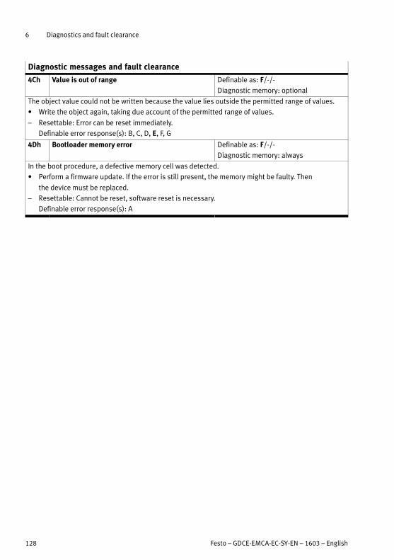
6 Diagnostics and fault clearance
128 Festo – GDCE-EMCA-EC-SY-EN – 1603 – English
Diagnostic messages and fault clearance
4Ch Value is out of range Definable as: F/-/-
Diagnostic memory: optional
The object value could not be written because the value lies outside the permitted range of values.
Write the object again, taking due account of the permitted range of values.
– Resettable: Error can be reset immediately.
Definable error response(s): B, C, D, E, F, G
4Dh Bootloader memory error Definable as: F/-/-
Diagnostic memory: always
In the boot procedure, a defective memory cell was detected.
Perform a firmware update. If the error is still present, the memory might be faulty. Then
the device must be replaced.
– Resettable: Cannot be reset, software reset is necessary.
Definable error response(s): A
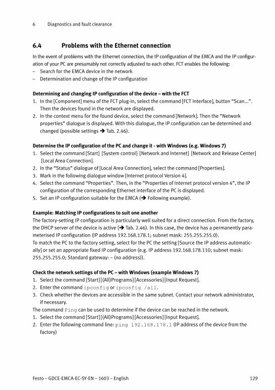
6 Diagnostics and fault clearance
Festo – GDCE-EMCA-EC-SY-EN – 1603 – English 129
6.4 Problems with the Ethernet connection
In the event of problems with the Ethernet connection, the IP configuration of the EMCA and the IP configur
ation of your PC are presumably not correctly adjusted to each other. FCT enables the following:
– Search for the EMCA device in the network
– Determination and change of the IP configuration
Determining and changing IP configuration of the device – with the FCT
1. In the [Component] menu of the FCT plug-in, select the command [FCT Interface], button “Scan...”.
Then the devices found in the network are displayed.
2. In the context menu for the found device, select the command [Network]. Then the “Network
properties” dialogue is displayed. With this dialogue, the IP configuration can be determined and
changed (possible settings Tab. 2.46).
Determine the IP configuration of the PC and change it - with Windows (e.g. Windows 7)
1. Select the command [Start] [System control] [Network and Internet] [Network and Release Center]
[Local Area Connection].
2. In the “Status” dialogue of [Local Area Connection], select the command [Properties].
3. Mark in the following dialogue window [Internet protocol Version 4].
4. Select the command “Properties”. Then, in the “Properties of Internet protocol version 4”, the IP
configuration of the corresponding Ethernet interface of the PC is displayed.
5. Set an IP configuration suitable for the EMCA ( Following example).
Example: Matching IP configurations to suit one another
The factory-setting IP configuration is particularly well suited for a direct connection. From the factory,
the DHCP server of the device is active ( Tab. 2.46). In this case, the device has a permanently para
meterised IP configuration (IP address 192.168.178.1; subnet mask: 255.255.255.0).
To match the PC to the factory setting, select for the PC the setting [Source the IP address automatic
ally] or set an appropriate fixed IP configuration (e.g. IP address 192.168.178.110; subnet mask:
255.255.255.0; Standard gateway: – (no address)).
Check the network settings of the PC – with Windows (example Windows 7)
1. Select the command [Start] [(All)Programs] [Accessories] [Input Request].
2. Enter the command ipconfig or ipconfig /all.
3. Check whether the devices are accessible in the same subnet. Contact your network administrator,
if necessary.
The command Ping can be used to determine if the device can be reached in the network.
1. Select the command [Start] [(All)Programs] [Accessories] [Input Request].
2. Enter the following command line: ping 192.168.178.1 (IP address of the device from the
factory)
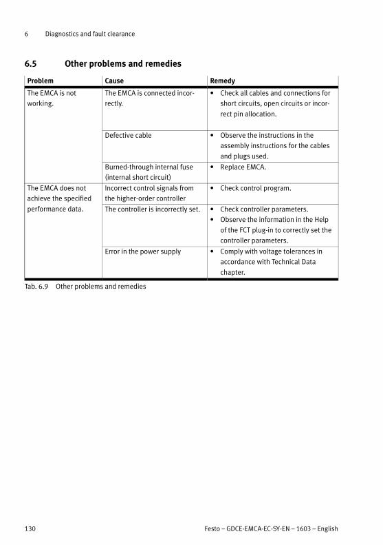
6 Diagnostics and fault clearance
130 Festo – GDCE-EMCA-EC-SY-EN – 1603 – English
6.5 Other problems and remedies
Problem Cause Remedy
The EMCA is not
working.
The EMCA is connected incor
rectly.
Check all cables and connections for
short circuits, open circuits or incor
rect pin allocation.
Defective cable Observe the instructions in the
assembly instructions for the cables
and plugs used.
Burned-through internal fuse
(internal short circuit)
Replace EMCA.
The EMCA does not
achieve the specified
performance data.
Incorrect control signals from
the higher-order controller
Check control program.
The controller is incorrectly set. Check controller parameters.
Observe the information in the Help
of the FCT plug-in to correctly set the
controller parameters.
Error in the power supply Comply with voltage tolerances in
accordance with Technical Data
chapter.
Tab. 6.9 Other problems and remedies

7 Maintenance, care, repair and replacement
Festo – GDCE-EMCA-EC-SY-EN – 1603 – English 131
7 Maintenance, care, repair and replacement
7.1 Maintenance and care
Warning
Rapidly rotating motor shaft with high torque.
Clothing, jewellery and hair can be caught and wrapped around the shaft. People can be
injured as a result.
Make sure that clothing, jewellery or hair can not be caught by the rotating motor
shaft.
Ensure that clothing fits tightly.
Hair nets must be worn with long hair.
Warning
Danger of burns from hot housing surfaces.
Contact with the motor housing can cause burn injuries. This can frighten people and
cause them to act in an unpredictable manner. This can lead to other forms of secondary
damage.
Make sure that unintentional contact is not possible.
Inform operating and maintenance staff about the possible hazards.
Note
Gas formation with fire risk.
If cleaning agents make contact with the hot surface of the motor, gases can form and
ignite.
Prior to cleaning work, let the drive cool down to room temperature.
Pay attention to the instructions for use of the cleaning agent.
Caution
Uncontrolled drive motion may cause personal injury and material damage.
Before carrying out mounting, installation and maintenance work:
Switch off power supply.
Secure the power supplies against accidental reactivation.
Caution
Rapidly rotating motor shaft with high torque.
Contact with the motor shaft can cause burn injuries and abrasions.
Ensure that the rotating motor shaft and components attached to it cannot be touched.
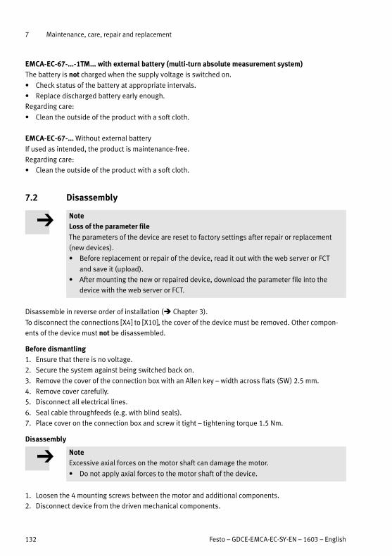
7 Maintenance, care, repair and replacement
132 Festo – GDCE-EMCA-EC-SY-EN – 1603 – English
EMCA-EC-67-...-1TM... with external battery (multi-turn absolute measurement system)
The battery is not charged when the supply voltage is switched on.
Check status of the battery at appropriate intervals.
Replace discharged battery early enough.
Regarding care:
Clean the outside of the product with a soft cloth.
EMCA-EC-67-... Without external battery
If used as intended, the product is maintenance-free.
Regarding care:
Clean the outside of the product with a soft cloth.
7.2 Disassembly
Note
Loss of the parameter file
The parameters of the device are reset to factory settings after repair or replacement
(new devices).
Before replacement or repair of the device, read it out with the web server or FCT
and save it (upload).
After mounting the new or repaired device, download the parameter file into the
device with the web server or FCT.
Disassemble in reverse order of installation ( Chapter 3).
To disconnect the connections [X4] to [X10], the cover of the device must be removed. Other compon
ents of the device must not be disassembled.
Before dismantling
1. Ensure that there is no voltage.
2. Secure the system against being switched back on.
3. Remove the cover of the connection box with an Allen key – width across flats (SW) 2.5 mm.
4. Remove cover carefully.
5. Disconnect all electrical lines.
6. Seal cable throughfeeds (e.g. with blind seals).
7. Place cover on the connection box and screw it tight – tightening torque 1.5 Nm.
Disassembly
Note
Excessive axial forces on the motor shaft can damage the motor.
Do not apply axial forces to the motor shaft of the device.
1. Loosen the 4 mounting screws between the motor and additional components.
2. Disconnect device from the driven mechanical components.

7 Maintenance, care, repair and replacement
Festo – GDCE-EMCA-EC-SY-EN – 1603 – English 133
7.3 Repair
Repair or maintenance of the product is not permissible. If necessary, replace the complete
product.
7.4 Replacement and disposal
Observe the instructions on dismantling in chapter 7.2.
7.4.1 Disposal
Observe the local regulations for environmentally friendly disposal of electronic modules.
The product is RoHS-compliant. The material used in the packaging has been specifically
chosen for its recyclability.

A Technical appendix
134 Festo – GDCE-EMCA-EC-SY-EN – 1603 – English
A Technical appendix
A.1 Technical data
A.1.1 General technical data
General technical data EMCA-EC-67-...
Type name code EMCA
Type of mounting – Screw-clamped
– With through-hole
Mounting position Any
Controller operating mode PWM-MOSFET power output stage
Cascade controller with
– P position controller
– PI speed controller
– PI current controller
Parameterisation interface Ethernet
Ethernet, supported protocols TCP/IP
Control interface protocol CANopen
Protective functions – I²t monitoring
– Temperature monitoring
– Current monitoring
– Voltage failure detection
– Following error monitoring
– Software end-position detection
Temperature monitoring – Silicon absolute temperature sensor
– Automatic switch-off in event of over-temper
ature
Tab. A.1 Technical data: general
A.1.2 Product conformity and certifications
Product conformity and certifications EMCA-EC-67-...
CE marking (declaration of conformity
www.festo.com/sp)
according to EU Machinery Directive 2006/42/EC
according to EU-EMC directive 2014/30/EU1)
Additional certifications RCM mark2)
c UL us - Recognised (OL)2)
1) The component is intended for industrial use. Outside of industrial environments, e.g. in commercial and mixed-residential areas,
actions to suppress interference may have to be taken.
2) Only valid for product variants with corresponding marking
Tab. A.2 Technical data: product conformity and certifications

A Technical appendix
Festo – GDCE-EMCA-EC-SY-EN – 1603 – English 135
A.1.3 Mechanical data
Dimensions and weight EMCA-EC-67-S-... EMCA-EC-67-M-...
Dimensions (H*W*D) Section 3.1
Product weight
EMCA without holding brake [B]
and without multi-turn absolute
measurement system [M]
[g] 1900 2260
Option multi-turn absolute
measurement system [M]
[g] 25
Option holding brake [B] [g] 350
Tab. A.3 Technical data: general
A.1.4 Operating and environmental conditions
Operating and environmental conditions EMCA-EC-67-...
Ambient temperature
At nominal power [°C] 0 … +20
With power reduction of 1,75 %
per °C:
[°C] 20 ... 50
Storage temperature [°C] -25 … +70
Relative air humidity at 25 °C [%] 0 … 95 (non-condensing)
Degree of protection
EMCA-... (without S1) IP54
EMCA-...-S1 IP65; motor shaft IP54
Vibration and shock resistance (in accordance with DIN EN 60068)1)
Transport 3.5 mm path at 2 … 9 Hz;
1 g acceleration at 9 ... 200 Hz
– Vibration (part 2-6)
– Shock (part 2-27)
– Continuous shock (part 2-29)
Severity level1) 2
Severity level1) 2
-
1) Explanation of the severity level Table “Explanation of vibration and shock – severity level”
Tab. A.4 Technical data: operation and ambient conditions

A Technical appendix
136 Festo – GDCE-EMCA-EC-SY-EN – 1603 – English
Explanation of vibration and shock – severity level
Vibration load
Frequency range [Hz] Acceleration [m/s2] Deflection [mm]
SL1 SL2 SL1 SL2 SL1 SL2
2 … 8 2 … 8 – – ±3.5 ±3.5
8 … 27 8 … 27 10 10 – –
27 … 58 27 … 60 – – ±0.15 ±0.35
58 … 160 60 … 160 20 50 – –
160 … 200 160 … 200 10 10 – –
Shock load
Acceleration [m/s2] Duration [ms] Shocks per direction
SL1 SL2 SL1 SL2 SL1 SL2
±150 ±300 11 11 5 5
Continuous shock load
Acceleration [m/s2] Duration [ms] Shocks per direction
±150 6 1000
A.1.5 Data on the integrated motor
Motor data EMCA-EC-67-S-... EMCA-EC-67-M-...
Nominal power [W] 120 150
Nominal torque [Nm] 0.37 0.45
Nominal rotary speed [rpm] 3100 3150
Max. rotational speed [rpm] 3500 3300
Mass moment of inertia of rotor [kg cm²] 0.175 0.301
Perm. axial shaft load [N] 60 60
Perm. radial shaft load [N] 100 100
Tab. A.5 Motor data

A Technical appendix
Festo – GDCE-EMCA-EC-SY-EN – 1603 – English 137
A.1.6 Data on the integrated rotary position encoder
Rotary position encoder EMCA-EC-67-...-1TE... EMCA-EC-67-...-1TM...
Rotary position encoder Absolute single turn
encoder
Absolute multi-turn
encoder
Rotary position encoder measuring principle Magnetic
Resolution [bit] 12 (4096 increments per revolution)
[°] Approx. 0.088
Absolute encoder operating duration (at medium ambient temperature)
Without external battery – 7 days
With external battery 6 months
Duration of charge until the storage
duration without external battery is
reached
[h] 24
Tab. A.6 Encoder data
A.1.7 Holding brake (only EMCA-EC-...-...-B)
Holding brake (optional) EMCA-EC-67-...-...B
Brake holding torque1) [Nm] 1
Brake power consumption [W] 9
Mass moment of inertia, brake [kg cm²] 0.021
1) Nominal values after run-in period at plant. Prolonged periods without operation (e.g. storage) can reduce these values, for
example, as a result of settling processes. This effect can be eliminated through repeated operation at low rotational speed.
Tab. A.7 Holding brake (optional)
A.1.8 Parameterisation interface [X1]
Ethernet EMCA-EC-67-...
Connection design Plug connector M12, 5-pin, D-coded
Max. transmission rate [Mbit/s] 100
Supported protocols TCP/IP
Tab. A.8 Connection data: parameterisation interface [X1]
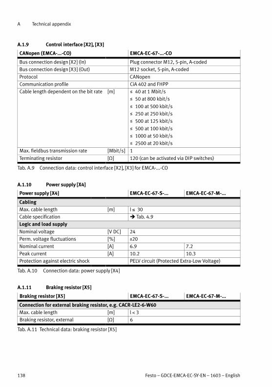
A Technical appendix
138 Festo – GDCE-EMCA-EC-SY-EN – 1603 – English
A.1.9 Control interface [X2], [X3]
CANopen (EMCA-...-CO) EMCA-EC-67-...-CO
Bus connection design [X2] (In) Plug connector M12, 5-pin, A-coded
Bus connection design [X3] (Out) M12 socket, 5-pin, A-coded
Protocol CANopen
Communication profile CiA 402 and FHPP
Cable length dependent on the bit rate [m] 40 at 1 Mbit/s
50 at 800 kbit/s
100 at 500 kbit/s
250 at 250 kbit/s
500 at 125 kbit/s
500 at 100 kbit/s
1000 at 50 kbit/s
2500 at 20 kbit/s
Max. fieldbus transmission rate [Mbit/s] 1
Terminating resistor [Ω] 120 (can be activated via DIP switches)
Tab. A.9 Connection data: control interface [X2], [X3] for EMCA-...-CO
A.1.10 Power supply [X4]
Power supply [X4] EMCA-EC-67-S-... EMCA-EC-67-M-...
Cabling
Max. cable length [m] l 30
Cable specification Tab. 4.9
Logic and load supply
Nominal voltage [V DC] 24
Perm. voltage fluctuations [%] ±20
Nominal current [A] 6.9 7.2
Peak current [A] 10.2 10.3
Protection against electric shock PELV circuit (Protected Extra-Low Voltage)
Tab. A.10 Connection data: power supply [X4]
A.1.11 Braking resistor [X5]
Braking resistor [X5] EMCA-EC-67-S-... EMCA-EC-67-M-...
Connection for external braking resistor, e.g. CACR-LE2-6-W60
Max. cable length [m] l 3
Braking resistor, external [Ω] 6
Tab. A.11 Technical data: braking resistor [X5]
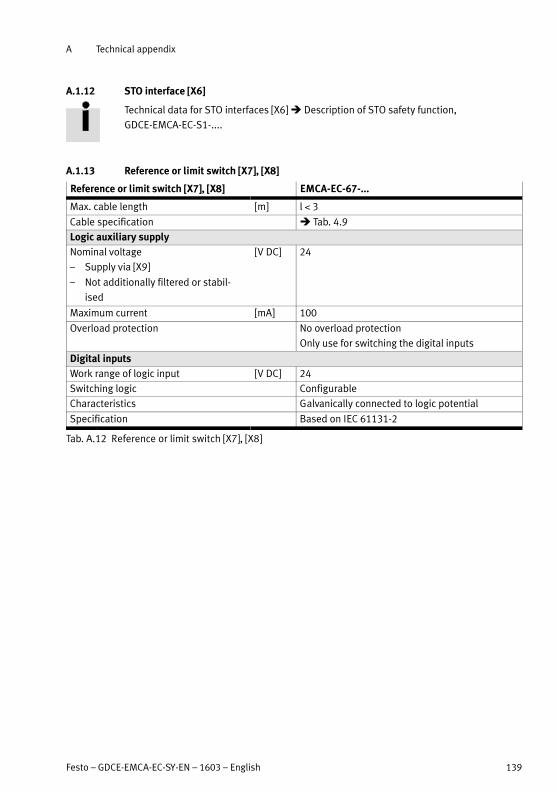
A Technical appendix
Festo – GDCE-EMCA-EC-SY-EN – 1603 – English 139
A.1.12 STO interface [X6]
Technical data for STO interfaces [X6] Description of STO safety function,
GDCE-EMCA-EC-S1-....
A.1.13 Reference or limit switch [X7], [X8]
Reference or limit switch [X7], [X8] EMCA-EC-67-...
Max. cable length [m] l 3
Cable specification Tab. 4.9
Logic auxiliary supply
Nominal voltage
– Supply via [X9]
– Not additionally filtered or stabil
ised
[V DC] 24
Maximum current [mA] 100
Overload protection No overload protection
Only use for switching the digital inputs
Digital inputs
Work range of logic input [V DC] 24
Switching logic Configurable
Characteristics Galvanically connected to logic potential
Specification Based on IEC 61131-2
Tab. A.12 Reference or limit switch [X7], [X8]
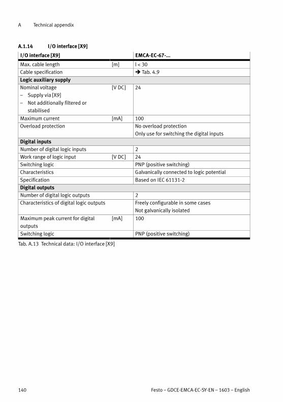
A Technical appendix
140 Festo – GDCE-EMCA-EC-SY-EN – 1603 – English
A.1.14 I/O interface [X9]
I/O interface [X9] EMCA-EC-67-...
Max. cable length [m] l 30
Cable specification Tab. 4.9
Logic auxiliary supply
Nominal voltage
– Supply via [X9]
– Not additionally filtered or
stabilised
[V DC] 24
Maximum current [mA] 100
Overload protection No overload protection
Only use for switching the digital inputs
Digital inputs
Number of digital logic inputs 2
Work range of logic input [V DC] 24
Switching logic PNP (positive switching)
Characteristics Galvanically connected to logic potential
Specification Based on IEC 61131-2
Digital outputs
Number of digital logic outputs 2
Characteristics of digital logic outputs Freely configurable in some cases
Not galvanically isolated
Maximum peak current for digital
outputs
[mA] 100
Switching logic PNP (positive switching)
Tab. A.13 Technical data: I/O interface [X9]

A Technical appendix
Festo – GDCE-EMCA-EC-SY-EN – 1603 – English 141
A.1.15 Connection for external battery [X10] (only EMCA-EC-67-...-1TM)
Connection for external battery [X10] EMCA-EC-67-...
Max. cable length [m] 3
Cable specification Tab. 4.9
Voltage [V DC] 9
Tab. A.14 Connection for external battery [X10]
A.1.16 Materials
1
2
34
5
6
22
Materials EMCA-EC-67-...
Housing
– Connection box 1 Polymer
– Lower housing part (power electronics) 3 Die-cast zinc
Seal 2 NBR
Motor
– Shaft 4 Steel
– Flange 5 Die-cast zinc
– Housing profile 6 Aluminium
Note on materials – Contains paint-wetting impairment
substances
Tab. A.15 Technical data: materials

B Glossary
142 Festo – GDCE-EMCA-EC-SY-EN – 1603 – English
B Glossary
Term/abbreviation Description
AZ (= Axis Zero point) Axis zero point Chapter 2.4.1
DIN Digital input
DOUT Digital output
EMC Electromagnetic compatibility
FCT Parameterisation and commissioning software
(FCT = Festo Configuration Tool)
FHPP Festo Handling and Positioning Profile; device profile for motor controllers
and drives from Festo
Following error The deviation between the setpoint position (in accordance with the
pre-calculated course of the path) and the actual position is calculated
during the execution of a positioning record. This deviation is designated
a following error.
FPC Festo Parameter Channel
The controller can access all parameter values of the motor controller via
the parameter channel of the FHPP device profile.
Homing Overview of the dimension reference system Chapter 2.4.1
I/O Input/output
Jog mode Manual control of the drive Chapter 2.4.3
MC Motion Complete (Target recognition)
PLC/IPC Programmable logic controller/industrial PC
PZ (= project zero
point)
Project zero point Chapter 2.4.1
REF (= REFerence
point)
Reference point Chapter 2.4.1
Reference switch Proximity sensor for defining the reference point
Software end
position
Overview of the dimension reference system Chapter 2.4.1
Teaching Transfer of the current position as a parameter Chapter 2.4.4
Tab. B.1 Product-specific terms and abbreviations
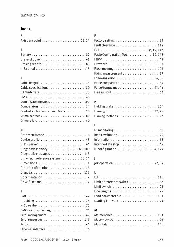
EMCA-EC-67-...-CO
Festo – GDCE-EMCA-EC-SY-EN – 1603 – English 143
Index
A
Axis zero point 23, 24. . . . . . . . . . . . . . . . . . . . . .
B
Battery 89. . . . . . . . . . . . . . . . . . . . . . . . . . . . . . .
Brake chopper 61. . . . . . . . . . . . . . . . . . . . . . . . .
Braking resistor 85. . . . . . . . . . . . . . . . . . . . . . . .
– External 138. . . . . . . . . . . . . . . . . . . . . . . . . . . .
C
Cable lengths 75. . . . . . . . . . . . . . . . . . . . . . . . . .
Cable specifications 80. . . . . . . . . . . . . . . . . . . . .
CAN interface 78. . . . . . . . . . . . . . . . . . . . . . . . . .
CiA 402 48. . . . . . . . . . . . . . . . . . . . . . . . . . . . . . .
Commissioning steps 102. . . . . . . . . . . . . . . . . . .
Comparators 54. . . . . . . . . . . . . . . . . . . . . . . . . .
Control section and connections 20. . . . . . . . . . .
Crimp contact 80. . . . . . . . . . . . . . . . . . . . . . . . . .
Crimp pliers 80. . . . . . . . . . . . . . . . . . . . . . . . . . .
D
Data matrix code 8. . . . . . . . . . . . . . . . . . . . . . . .
Device profile 48. . . . . . . . . . . . . . . . . . . . . . . . . .
DHCP server 64. . . . . . . . . . . . . . . . . . . . . . . . . . .
Diagnostic memory 63, 109. . . . . . . . . . . . . . . . .
Diagnostic messages 113. . . . . . . . . . . . . . . . . . .
Dimension reference system 23, 24. . . . . . . . . . .
Dimensions 71. . . . . . . . . . . . . . . . . . . . . . . . . . . .
Direction of rotation 23. . . . . . . . . . . . . . . . . . . . .
Disposal 133. . . . . . . . . . . . . . . . . . . . . . . . . . . . .
Documentation 7. . . . . . . . . . . . . . . . . . . . . . . . .
Drive functions 22. . . . . . . . . . . . . . . . . . . . . . . . .
E
EMC 142. . . . . . . . . . . . . . . . . . . . . . . . . . . . . . . .
– Cabling 75. . . . . . . . . . . . . . . . . . . . . . . . . . . . .
– Screening 75. . . . . . . . . . . . . . . . . . . . . . . . . . .
EMC-compliant wiring 75. . . . . . . . . . . . . . . . . . .
Error management 62. . . . . . . . . . . . . . . . . . . . . .
Error responses 113. . . . . . . . . . . . . . . . . . . . . . .
Errors 62. . . . . . . . . . . . . . . . . . . . . . . . . . . . . . . .
Ethernet interface 76. . . . . . . . . . . . . . . . . . . . . .
F
Factory setting 93. . . . . . . . . . . . . . . . . . . . . . . . .
Fault clearance 114. . . . . . . . . . . . . . . . . . . . . . . .
FCT 8, 19, 142. . . . . . . . . . . . . . . . . . . . . . . . . . . .
Festo Configuration Tool 19, 142. . . . . . . . . . . . .
FHPP 48. . . . . . . . . . . . . . . . . . . . . . . . . . . . . . . . .
Firmware 8. . . . . . . . . . . . . . . . . . . . . . . . . . . . . . .
Flash memory 108. . . . . . . . . . . . . . . . . . . . . . . . .
Flying measurement 69. . . . . . . . . . . . . . . . . . . . .
Following error 54, 56. . . . . . . . . . . . . . . . . . . . . .
Force comparator 60. . . . . . . . . . . . . . . . . . . . . . .
Force/torque mode 43, 44. . . . . . . . . . . . . . . . . .
Free run-out 62. . . . . . . . . . . . . . . . . . . . . . . . . . .
H
Holding brake 137. . . . . . . . . . . . . . . . . . . . . . . . .
Homing 22, 26. . . . . . . . . . . . . . . . . . . . . . . . . . . .
Homing methods 27. . . . . . . . . . . . . . . . . . . . . . .
I
I²t monitoring 61. . . . . . . . . . . . . . . . . . . . . . . . . .
Index evaluation 26. . . . . . . . . . . . . . . . . . . . . . . .
Information 62. . . . . . . . . . . . . . . . . . . . . . . . . . . .
Intermediate stop 45. . . . . . . . . . . . . . . . . . . . . .
IP configuration 94, 129. . . . . . . . . . . . . . . . . . . .
J
Jog operation 22, 34. . . . . . . . . . . . . . . . . . . . . . .
L
LED 111. . . . . . . . . . . . . . . . . . . . . . . . . . . . . . . . .
Limit or reference switch 87. . . . . . . . . . . . . . . . .
Limit switch 25. . . . . . . . . . . . . . . . . . . . . . . . . . .
Line lengths 75. . . . . . . . . . . . . . . . . . . . . . . . . . .
Load parameter file 103. . . . . . . . . . . . . . . . . . . .
Loading firmware 93. . . . . . . . . . . . . . . . . . . . . . .
M
Maintenance 133. . . . . . . . . . . . . . . . . . . . . . . . . .
Master control 98. . . . . . . . . . . . . . . . . . . . . . . . .
Materials 141. . . . . . . . . . . . . . . . . . . . . . . . . . . .

EMCA-EC-67-...-CO
144 Festo – GDCE-EMCA-EC-SY-EN – 1603 – English
Message
– Following error 56. . . . . . . . . . . . . . . . . . . . . . .
– Motion complete 55. . . . . . . . . . . . . . . . . . . . .
– Standstill monitoring 57. . . . . . . . . . . . . . . . . .
Motion complete 54. . . . . . . . . . . . . . . . . . . . . . .
Motor current 61. . . . . . . . . . . . . . . . . . . . . . . . . .
Mounting 73. . . . . . . . . . . . . . . . . . . . . . . . . . . . .
N
Network connection 95. . . . . . . . . . . . . . . . . . . . .
O
Optimise controller setting 105. . . . . . . . . . . . . .
P
Password protection 96. . . . . . . . . . . . . . . . . . . .
PLC 142. . . . . . . . . . . . . . . . . . . . . . . . . . . . . . . . .
Plug connector 80. . . . . . . . . . . . . . . . . . . . . . . . .
Position comparator 59. . . . . . . . . . . . . . . . . . . .
Positioning mode 36. . . . . . . . . . . . . . . . . . . . . . .
Product key 8. . . . . . . . . . . . . . . . . . . . . . . . . . . .
Product label 8. . . . . . . . . . . . . . . . . . . . . . . . . . .
Project zero point 23, 24. . . . . . . . . . . . . . . . . . . .
Protective functions 61. . . . . . . . . . . . . . . . . . . . .
Q
Quick-stop 45, 62. . . . . . . . . . . . . . . . . . . . . . . . .
R
Record deceleration 62. . . . . . . . . . . . . . . . . . . . .
Record selection 48. . . . . . . . . . . . . . . . . . . . . . .
Record sequencing 52. . . . . . . . . . . . . . . . . . . . . .
Reference point 23, 24. . . . . . . . . . . . . . . . . . . . .
Reference switch 87. . . . . . . . . . . . . . . . . . . . . . .
Repair 133. . . . . . . . . . . . . . . . . . . . . . . . . . . . . . .
S
Safety function 103. . . . . . . . . . . . . . . . . . . . . . . .
Safety instructions 11. . . . . . . . . . . . . . . . . . . . . .
Screening 75. . . . . . . . . . . . . . . . . . . . . . . . . . . . .
Seal inserts 81. . . . . . . . . . . . . . . . . . . . . . . . . . .
Serial number 8. . . . . . . . . . . . . . . . . . . . . . . . . . .
Software end position 25. . . . . . . . . . . . . . . . . . .
Speed comparator 59. . . . . . . . . . . . . . . . . . . . . .
Speed mode 39. . . . . . . . . . . . . . . . . . . . . . . . . . .
Standstill monitoring 54, 57. . . . . . . . . . . . . . . . .
STO (safe torque off ) 86. . . . . . . . . . . . . . . . . . . .
Stroke limit 40. . . . . . . . . . . . . . . . . . . . . . . . . . . .
T
Technical data 134. . . . . . . . . . . . . . . . . . . . . . . .
Temperature monitoring 61. . . . . . . . . . . . . . . . .
Terminating resistor 65, 79. . . . . . . . . . . . . . . . . .
Time comparator 60. . . . . . . . . . . . . . . . . . . . . . .
Transport and storage conditions 13. . . . . . . . . .
U
Use for intended purpose 12. . . . . . . . . . . . . . . .
V
Version 8. . . . . . . . . . . . . . . . . . . . . . . . . . . . . . . .
Voltage monitoring 61. . . . . . . . . . . . . . . . . . . . . .
W
Warning 62. . . . . . . . . . . . . . . . . . . . . . . . . . . . . .
Web server 19, 99, 100. . . . . . . . . . . . . . . . . . . .
Y
Year of manufacture 8. . . . . . . . . . . . . . . . . . . . . .


Reproduction, distribution or sale of this document or communication of its contents to others without express authorization isprohibited. Offenders will be liable for damages. All rights reserved in the event that a patent, utility model or design patent isregistered.
Copyright:Festo AG & Co. KGPostfach73726 EsslingenGermany
Phone:+49 711 347-0
Fax:+49 711 347-2144
E-mail:[email protected]
Internet:www.festo.com
Original: de