emc test reportdlsvr04.asus.com/pub/asus/mb/lga1150/h81t_r2/rep... · cerpass technology...
TRANSCRIPT

CERPASS TECHNOLOGY (SUZHOU)CO., LTD Report No.: SECE1310105-A
Cerpass Technology (Suzhou) Co., Ltd Issued Date : Jun 11, 2014
TEL: +86-512-6917-5888 FAX: +86-512-6917-5666 Page No. : 1 of 92
EMC TEST REPORT
Authorized under Declaration of Conformity
According to
EN 55022:2010+AC:2011 (Class B) EN 55024 : 2010
EN 61000-3-2: 2006+ A2: 2009 IEC 61000-4-2 : 2008
EN 61000-3-3 : 2008 IEC 61000-4-3 : 2006+A1:2007+A:2010
AS/NZS CISPR 22: 2009+A1:2010 (Class B) IEC 61000-4-4 : 2012
IEC 61000-4-5 : 2005
IEC 61000-4-6 : 2008
IEC 61000-4-8 : 2009
IEC 61000-4-11 : 2004
Applicant : ASUSTEK COMPUTER INC.
Address : 4F, No. 150, LI-TE Rd., PEITOU, TAIPEI 112, TAIWAN
Equipment : Motherboard
Model No. : H81T R2.0
Brand name : ASUS
The test result refers exclusively to the test presented test model / sample.
Without written approval of Cerpass Technology (Suzhou) Corp. the test report shall not
be reproduced except in full.
This test report is only applicable to European Community.
The test report must not be used by the clients to claim product certification approval by
NVLAP or any agency of the Government.
Test date: Jun 04~ Jun 11, 2014

CERPASS TECHNOLOGY (SUZHOU)CO., LTD Report No.: SECE1310105-A
Cerpass Technology (Suzhou) Co., Ltd Issued Date : Jun 11, 2014
TEL: +86-512-6917-5888 FAX: +86-512-6917-5666 Page No. : 2 of 92
Contents
CERTIFICATE OF COMPLIANCE ....................................................................... 5
1. Summary of Test Procedure and Test Results .................................................... 6
2. Immunity Testing Performance Criteria Definition ................................................ 7
3. Test Configuration of Equipment under Test ...................................................... 8
3.1. Manufacturer .................................................................................................................................... 8
3.2. Feature of Equipment under Test ..................................................................................................... 9
3.3. Test Manner ................................................................................................................................... 11
3.4. Description of Test System ............................................................................................................. 12
3.5. Connection Diagram of Test System .............................................................................................. 13
3.6. General Information of Test ............................................................................................................ 14
3.7. Measurement Uncertainty .............................................................................................................. 14
4. Test of Conducted Emission ........................................................................ 16
4.1. Test Limit ........................................................................................................................................ 16
4.2. Test Procedures ............................................................................................................................. 17
4.3. Typical Test Setup .......................................................................................................................... 17
4.4. Measurement equipment ............................................................................................................... 18
4.5. Test Result and Data ...................................................................................................................... 19
4.6. Test Photographs ........................................................................................................................... 25
5. Test of Radiated Emission ......................................................................... 28
5.1. Test Limit ........................................................................................................................................ 28
5.2. Test Procedures ............................................................................................................................. 29
5.3. Typical test Setup ........................................................................................................................... 30
5.4. Measurement equipment ............................................................................................................... 31
5.5. Test Result and Data (30MHz ~ 1000MHz) ................................................................................... 32
5.6. Test Result and Data (1000MHz ~ 6000MHz) ............................................................................... 34
5.7. Test Photographs (30MHz ~ 1000MHz) ......................................................................................... 36
5.8. Test Photographs (1000MHz ~ 6000MHz) ..................................................................................... 37
6. Harmonics Test ..................................................................................... 38
6.1. Limits Of Harmonics Current Measurement ................................................................................... 38
6.2. Measurement equipment ............................................................................................................... 39
6.3. Test Result and Data ...................................................................................................................... 40
6.4. Test Photographs ........................................................................................................................... 42
7. Voltage Fluctuations Test .......................................................................... 43
7.1. Test Procedure ............................................................................................................................... 43
7.2. Measurement equipment ............................................................................................................... 43
7.3. Test Result and Data ...................................................................................................................... 44
7.4. Test Photographs ........................................................................................................................... 46
8. Electrostatic Discharge Immunity Test ........................................................... 47
8.1. Test Procedure ............................................................................................................................... 47
8.2. Test Setup for Tests Performed in Laboratory ................................................................................ 48
8.3. Test Severity Levels ....................................................................................................................... 49
8.4. Measurement equipment ............................................................................................................... 49

CERPASS TECHNOLOGY (SUZHOU)CO., LTD Report No.: SECE1310105-A
Cerpass Technology (Suzhou) Co., Ltd Issued Date : Jun 11, 2014
TEL: +86-512-6917-5888 FAX: +86-512-6917-5666 Page No. : 3 of 92
8.5. Test Result and Data ...................................................................................................................... 50
8.6. Test Photographs ........................................................................................................................... 51
9. Radio Frequency electromagnetic field immunity test ............................................ 54
9.1. Test Procedure ............................................................................................................................... 54
9.2. Test Severity Levels ....................................................................................................................... 55
9.3. Measurement equipment ............................................................................................................... 55
9.4. Test Result and Data ...................................................................................................................... 56
9.5. Test Photographs ........................................................................................................................... 57
10. Electrical Fast Transient/ Burst Immunity Test ................................................. 58
10.1. Test Procedure ............................................................................................................................ 58
10.2. Test Severity Levels .................................................................................................................... 59
10.3. Measurement equipment ............................................................................................................ 59
10.4. Test Result and Data ................................................................................................................... 60
10.5. Test Photographs ........................................................................................................................ 61
11. Surge Immunity Test ............................................................................... 62
11.1. Test Procedure ............................................................................................................................ 62
11.2. Test Severity Level ...................................................................................................................... 63
11.3. Measurement equipment ............................................................................................................ 63
11.4. Test Result and Data ................................................................................................................... 64
11.5. Test Photographs ........................................................................................................................ 65
12. Conduction Disturbances induced by Radio-Frequency Fields .................................... 66
12.1. Test Procedure ............................................................................................................................ 66
12.2. Test Severity Levels .................................................................................................................... 67
12.3. Measurement equipment ............................................................................................................ 67
12.4. Test Result and Data ................................................................................................................... 68
12.5. Test Photographs ........................................................................................................................ 69
13. Power Frequency Magnetic Field Immunity Tests ................................................ 70
13.1. Test Setup ................................................................................................................................. 70
13.2. Test Severity Levels .................................................................................................................... 70
13.3. Measurement equipment ............................................................................................................ 70
13.4. Test Result and Data ................................................................................................................... 71
13.5. Test Photographs ........................................................................................................................ 72
14. Voltage Dips and Voltage Interruptions Immunity Test Setup .................................. 73
14.1. Test Conditions ........................................................................................................................... 73
14.2. Measurement equipment ............................................................................................................ 73
14.3. Test Result and Data ................................................................................................................... 74
14.4. Test Photographs ........................................................................................................................ 75
15. Photographs of EUT ................................................................................ 76

CERPASS TECHNOLOGY (SUZHOU)CO., LTD Report No.: SECE1310105-A
Cerpass Technology (Suzhou) Co., Ltd Issued Date : Jun 11, 2014
TEL: +86-512-6917-5888 FAX: +86-512-6917-5666 Page No. : 4 of 92
History of this test report
ORIGINAL.
Additional attachment as following record:
Attachment No. Date Description
SECE1310105 Nov 04,2013 Original report
SECE1310105-A Jun 11,2014 First edition: Compare to H81T, H81T R2.0 add
support function of a new card colay
mSATA&mPCIe, H/W add IC--USB
HUB:GL852G-OHG12, pin-out:UHU1

CERPASS TECHNOLOGY (SUZHOU)CO., LTD Report No.: SECE1310105-A
Cerpass Technology (Suzhou) Co., Ltd Issued Date : Jun 11, 2014
TEL: +86-512-6917-5888 FAX: +86-512-6917-5666 Page No. : 5 of 92
CERTIFICATE OF COMPLIANCE
According to
EN 55022:2010+AC:2011 (Class B) EN 55024 : 2010
EN 61000-3-2: 2006+ A2: 2009 IEC 61000-4-2 : 2008
EN 61000-3-3 : 2008 IEC 61000-4-3 : 2006+A1:2007+A:2010
AS/NZS CISPR 22: 2009+A1:2010 (Class B) IEC 61000-4-4 : 2012
IEC 61000-4-5 : 2005
IEC 61000-4-6 : 2008
IEC 61000-4-8 : 2009
IEC 61000-4-11 : 2004
Applicant : ASUSTEK COMPUTER INC.
Address : 4F, No. 150, LI-TE Rd., PEITOU, TAIPEI 112, TAIWAN
Equipment : Motherboard
Model No. : H81T R2.0
Brand name : ASUS
I HEREBY CERTIFY THAT :
The measurements shown in this test report were made in accordance with the procedures
given in EUROPEAN COUNCIL DIRECTIVE 2004/108/EC.
The test was carried out on Jun 11, 2014at Cerpass Technology(Suzhou) Corp.
Signature
Miro Chueh/ Technical director
CERPASS TECHNOLOGY (SUZHOU)CO., LTD Report No.: SECE1310105-A
Cerpass Technology (Suzhou) Co., Ltd Issued Date : Jun 11, 2014
TEL: +86-512-6917-5888 FAX: +86-512-6917-5666 Page No. : 6 of 92
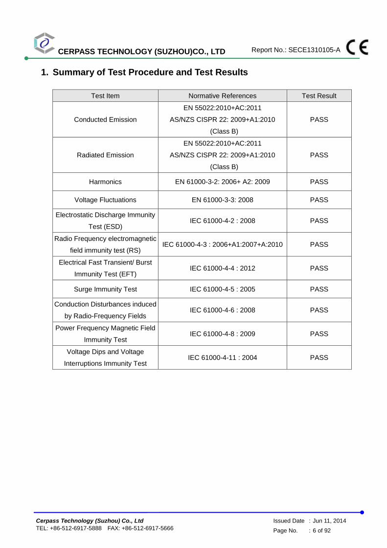
1. Summary of Test Procedure and Test Results
Test Item Normative References Test Result
Conducted Emission
EN 55022:2010+AC:2011
AS/NZS CISPR 22: 2009+A1:2010
(Class B)
PASS
Radiated Emission
EN 55022:2010+AC:2011
AS/NZS CISPR 22: 2009+A1:2010
(Class B)
PASS
Harmonics EN 61000-3-2: 2006+ A2: 2009 PASS
Voltage Fluctuations EN 61000-3-3: 2008 PASS
Electrostatic Discharge Immunity
Test (ESD) IEC 61000-4-2 : 2008 PASS
Radio Frequency electromagnetic
field immunity test (RS) IEC 61000-4-3 : 2006+A1:2007+A:2010 PASS
Electrical Fast Transient/ Burst
Immunity Test (EFT) IEC 61000-4-4 : 2012 PASS
Surge Immunity Test IEC 61000-4-5 : 2005 PASS
Conduction Disturbances induced
by Radio-Frequency Fields IEC 61000-4-6 : 2008 PASS
Power Frequency Magnetic Field
Immunity Test IEC 61000-4-8 : 2009 PASS
Voltage Dips and Voltage
Interruptions Immunity Test IEC 61000-4-11 : 2004 PASS

CERPASS TECHNOLOGY (SUZHOU)CO., LTD Report No.: SECE1310105-A
Cerpass Technology (Suzhou) Co., Ltd Issued Date : Jun 11, 2014
TEL: +86-512-6917-5888 FAX: +86-512-6917-5666 Page No. : 7 of 92
2. Immunity Testing Performance Criteria Definition
Criteria A:
The apparatus shell continues to operate as intended without operator intervention. No degradation of performance or loss of function is allowed below a performance level specified by the manufacturer, when the apparatus is used as intended. The performance level may be replaced by a permissible loss of performance. If the manufacturer does not specify the minimum performance level or the permissible performance loss, then either of these may be derived from the product description and documentation, and by what the user may reasonably expect from the equipment if used as intended.
Criteria B:
After test, the apparatus shell continues to operate as intended without operator intervention. No degradation of performance or loss of function is allowed, after the application of the phenomenon below a performance level specified by the manufacturer, when the apparatus is used as intended. The performance level may be replaced by a permissible loss of performance.
During the test, degradation of performance is however allowed. However, no change of operating state if stored data is allowed to persist after the test. If the manufacturer does not specify the minimum performance level or the permissible performance loss, then either of these may be derived from the product description and documentation, and by what the user may reasonably expect from the equipment if used as intended.
Criteria C:
Temporary loss of function is allowed, provided the functions is self-recoverable or can be restored by the operation of controls by the user in accordance with the manufacturer instructions.
Functions, and/or information stored in non-volatile memory, or protected by a battery backup, shall not be lost.

CERPASS TECHNOLOGY (SUZHOU)CO., LTD Report No.: SECE1310105-A
Cerpass Technology (Suzhou) Co., Ltd Issued Date : Jun 11, 2014
TEL: +86-512-6917-5888 FAX: +86-512-6917-5666 Page No. : 8 of 92
3. Test Configuration of Equipment under Test
3.1. Manufacturer
Manufacturer (1) : MainTek Computer (Suzhou) Co., Ltd.
Address (1) : No. 233, Jinfeng Road, Suzhou City New District, Jiangsu, P.R. China
Manufacturer (2) : Danriver Technology (GZ) Inc.
Address (2) : No.16, BaoyingDadao, Guangzhou Free Trade Zone, Guangdong, P.R. China
Manufacturer (3) : Global Brands Manufacture Ltd
Address (3) : EMS Business unit Global Brands Manufacture Limited Yuyuan Industrial Estate,Huangjiang Town,Dongguan City,Guangdong, P.R.China
Manufacturer (4) : First International Computer(Suzhou)Inc
Address (4) : Export Processing Zone,No.200 Central SuhongRoad,SuZhou Industrial Park,Jiangsu, P.R.China
Manufacturer (5) : BOATEK ELECTRONIC CO.,LTD.
Address (5) : N0.124 bubugao road ,wushakongbavillage ,chang an, dong guan,guang dong province
Manufacturer (6) : Cal-Comp Electronics and Communications (suzhou) Co., Ltd
Address (6) : Wujiang Export Processing Zone,No688,Pangjin Road,Wujiang Economic
Development Zone, Jiangsu Province, China.
Manufacturer (7) : NBM Production (Dongguan)Co., Ltd
Address (7) : NO.51 Xinju Rd., Shangjiao community, ChanganTown, Dongguan City, Guangdong, P.R. China
Manufacturer (8) : INFO-TEK ELECTRONICS CO.,LTD
Address (8) : No. 183 JinfengRd.,Hi-tech Development Zone Suzhou,Jiangsu, P.R. China

CERPASS TECHNOLOGY (SUZHOU)CO., LTD Report No.: SECE1310105-A
Cerpass Technology (Suzhou) Co., Ltd Issued Date : Jun 11, 2014
TEL: +86-512-6917-5888 FAX: +86-512-6917-5666 Page No. : 9 of 92
3.2. Feature of Equipment under Test
Original:
Motherboard Model No.: H81T R2.0
AC Adapter
Model No.: BT-AG181EGF-HF
Input: 100-240V~2.2A 50-60Hz
Output: 19.5V 9.23A
DC Cable Shielded, 1.8m, with two ferrite cores bonded.
Key component List
Item Manufactory Model Specification
CPU Intel --- 2.0GHz
Memory SAMSUNG M471B5173BHO 4.0GB
HDD HGST HTS541075A9E680 750GB

CERPASS TECHNOLOGY (SUZHOU)CO., LTD Report No.: SECE1310105-A
Cerpass Technology (Suzhou) Co., Ltd Issued Date : Jun 11, 2014
TEL: +86-512-6917-5888 FAX: +86-512-6917-5666 Page No. : 10 of 92
First edition:
Motherboard Model No.: H81T R2.0
AC Adapter
Model No.: BT-AG181EGF-HF
Input: 100-240V~2.2A 50-60Hz
Output: 19.5V 9.23A
DC Cable Shielded, 1.8m, with two ferrite cores bonded.
Key component List
Item Manufactory Model Specification
CPU Intel HASWELL-1150 2.9GHz
Memory Hynix HMT112S6BFR6C 1.0GB
HDD SAMSUNG HM121HI/CNG 120GB
CPU Intel CPU Support Type LGA 1150
Memory
Memory Type DDR3
Memory size Min: 1042 MB
Max: 16 GB
Resolutin HDMI Max.resolutin: 1920*1200 60Hz
DVI Max.resolutin: 1920*1080 60Hz
Network: 10M/bps,100M/bps,1000M/bps
Back I/O Ports:
1 USB1.1&2.0 port 2
2 USB3.0 port 2
3 DVI port 1
4 HDMI port 1
5 RJ-45 port(10M/bps,100M/bps,1000M/bps) 1
6 Audio port 2
7 E-sate port 1

CERPASS TECHNOLOGY (SUZHOU)CO., LTD Report No.: SECE1310105-A
Cerpass Technology (Suzhou) Co., Ltd Issued Date : Jun 11, 2014
TEL: +86-512-6917-5888 FAX: +86-512-6917-5666 Page No. : 11 of 92
3.3. Test Manner
a. During testing, the interface cables and equipment positions were varied according to Europe
Standard.
b. The complete test system included the LCD Monitor, HDD, iPod, Earphone, Keyboard, Mouse,
Notebook PC and EUT for EMI test.
c. During the test, setup up the EUT and all system, turn on the power of all Equipments.
d. An executive program, “BurnInTest professional V6”, run the EMC test software “H”, “H” font
size No. is 11, CPU+RAM+2D+3D 100%.
e. An executive program, “WINTHRAX.EXE” was executed to read and write data from IPOD,
HDD.
f. During the disturbances at telecommunication port test, the condition of LAN utilization in
excess of 10%.
g. Make the EUT at the test mode and it is normal operation, and then test.
The pre-test modes for CE/RE
Test Mode 1: Full System with DVI(1920*1200@60Hz) and HDMI (1920*1200@60Hz) with
Status 1
Test Mode 2: Full System with DVI (1920*1200@60Hz) and HDMI (1920*1200@60Hz) with
Status 2
Test Mode 3: Full System with DVI (1280*1024@75Hz) and HDMI (1280*1024@75Hz) with
Status 1
Test Mode 4: Full System with DVI (640*480@60Hz) and HDMI (640*480@60Hz) with Status
1
The pre-test modes for H&F, ESD,RS,EFT, Surge, CS, PFM, Dips:
Test Mode 1:Full System with DVI(1920*1200@60Hz) and HDMI (1920*1200@60Hz) with
Status 1
The final test mode for CE/RE
Test Mode 1: Full System with DVI(1920*1200@60Hz) and HDMI (1920*1200@60Hz) with
Status 1
The final test mode modes for H&F, ESD,RS,EFT, Surge,CS,PFM,Dips:
Test Mode 1:Full System with DVI(1920*1200@60Hz) and HDMI (1920*1200@60Hz) with
Status 1
Note1:
Status1:USB 2.0 Port Connect to mouse and keyboard, USB3.0 port connect to HDD
Status2:USB 3.0 Port Connect to mouse and keyboard, USB2.0 port connect to Ipod
CERPASS TECHNOLOGY (SUZHOU)CO., LTD Report No.: SECE1310105-A
Cerpass Technology (Suzhou) Co., Ltd Issued Date : Jun 11, 2014
TEL: +86-512-6917-5888 FAX: +86-512-6917-5666 Page No. : 12 of 92
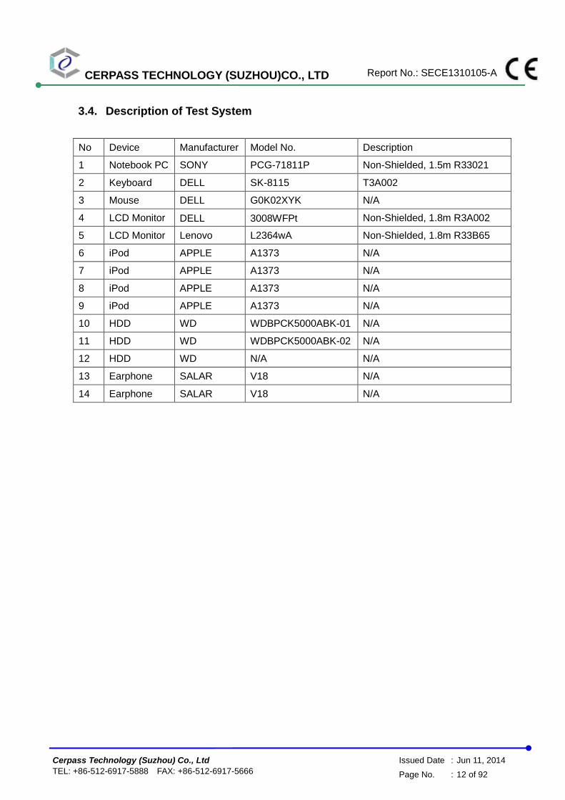
3.4. Description of Test System
No Device Manufacturer Model No. Description
1 Notebook PC SONY PCG-71811P Non-Shielded, 1.5m R33021
2 Keyboard DELL SK-8115 T3A002
3 Mouse DELL G0K02XYK N/A
4 LCD Monitor DELL 3008WFPt Non-Shielded, 1.8m R3A002
5 LCD Monitor Lenovo L2364wA Non-Shielded, 1.8m R33B65
6 iPod APPLE A1373 N/A
7 iPod APPLE A1373 N/A
8 iPod APPLE A1373 N/A
9 iPod APPLE A1373 N/A
10 HDD WD WDBPCK5000ABK-01 N/A
11 HDD WD WDBPCK5000ABK-02 N/A
12 HDD WD N/A N/A
13 Earphone SALAR V18 N/A
14 Earphone SALAR V18 N/A
CERPASS TECHNOLOGY (SUZHOU)CO., LTD Report No.: SECE1310105-A
Cerpass Technology (Suzhou) Co., Ltd Issued Date : Jun 11, 2014
TEL: +86-512-6917-5888 FAX: +86-512-6917-5666 Page No. : 13 of 92
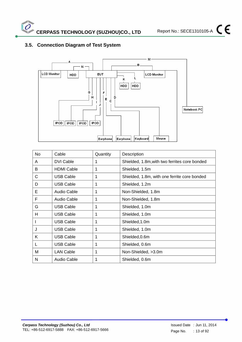
3.5. Connection Diagram of Test System
No Cable Quantity Description
A DVI Cable 1 Shielded, 1.8m,with two ferrites core bonded
B HDMI Cable 1 Shielded, 1.5m
C USB Cable 1 Shielded, 1.8m, with one ferrite core bonded
D USB Cable 1 Shielded, 1.2m
E Audio Cable 1 Non-Shielded, 1.8m
F Audio Cable 1 Non-Shielded, 1.8m
G USB Cable 1 Shielded, 1.0m
H USB Cable 1 Shielded, 1.0m
I USB Cable 1 Shielded,1.0m
J USB Cable 1 Shielded, 1.0m
K USB Cable 1 Shielded,0.6m
L USB Cable 1 Shielded, 0.6m
M LAN Cable 1 Non-Shielded, >3.0m
N Audio Cable 1 Shielded, 0.6m

CERPASS TECHNOLOGY (SUZHOU)CO., LTD Report No.: SECE1310105-A
Cerpass Technology (Suzhou) Co., Ltd Issued Date : Jun 11, 2014
TEL: +86-512-6917-5888 FAX: +86-512-6917-5666 Page No. : 14 of 92
3.6. General Information of Test
Test Site: Cerpass Technology (Suzhou) Co.,Ltd
Test Site Location : No.66,Tangzhuang Road, Suzhou Industrial Park, Jiangsu
215006, China
NVLAP LAB Code : 200814-0
FCC Registration Number : 916572, 331395
IC Registration Number : 7290A-1, 7290A-2
VCCI Registration Number :
T-1945 for Telecommunication Test
C-2919 for Conducted emission test
R-2670 for Radiated emission test below 1GHz
G-227 for Radiated emission test above 1GHz
Frequency Range
Investigated :
Conducted Emission Test: from 150kHz to 30 MHz
Radiated Emission Test: from 30 MHz to 1,000 MHz
Radiated Emission Test: from 1GHz to 6GHz
Test Distance :
The test distance of radiated emission below 1GHz from
antenna to EUT is 10 M.
The test distance of radiated emission above 1GHz from
antenna to EUT is 3 M.
LABORATORY ACCREDITATION
3.7. Measurement Uncertainty
Where relevant, the following measurement uncertainty levels have been estimated for tests performed
on the EUT as specified in CISPR 16-4-2:
Measurement Frequency Uncertainty
Conducted emissions 0.09MHz-30MHz +/- 1.2462 dB

CERPASS TECHNOLOGY (SUZHOU)CO., LTD Report No.: SECE1310105-A
Cerpass Technology (Suzhou) Co., Ltd Issued Date : Jun 11, 2014
TEL: +86-512-6917-5888 FAX: +86-512-6917-5666 Page No. : 15 of 92
Measurement Polarity Frequency Uncertainty
Radiated emissions
(below 1GHz)
H 30MHz ~ 200MHz +/- 4.0246dB
200MHz ~1000MHz +/- 3.8673dB
V 30MHz ~ 200MHz +/- 4.0242dB
200MHz ~1000MHz +/- 3.8688dB
Radiated emissions
(above 1GHz)
H 1000MHz ~18000MHz +/- 3.8856dB
18000MHz ~40000MHz +/- 3.8674dB
V 1000MHz ~18000MHz +/- 3.8852dB
18000MHz ~40000MHz +/- 3.8670dB
Measurement Uncertainty
ESD—Rise time tr 9%
ESD—Peak current Ip 2.5%
ESD—Current at 30 ns 1%
ESD—Current at 60 ns 4%
RS above 3GHz ±3.62dB
RS under 3GHz ±3.70dB
EFT—Rise time tr 4%
EFT—Peak current Ip 4%
EFT—Current 4%
Surge—Rise time tr 4%
Surge—Peak current Ip 4%
Surge—Current 4%
CS-CND ±0.80dB
CS-Clamp ±1.06dB
This uncertainty represents an expanded uncertainty expressed at approximately the 95% confidence level using a coverage factor of k=2.
Consistent with industry standard (e.g. CISPR 22: 2008, clause 11, Measurement Uncertainty) determining compliance with the limits shall be base on the results of the compliance measurement. Consequently the measure emissions being less than the maximum allowed emission result in this be a compliant test or passing test.

CERPASS TECHNOLOGY (SUZHOU)CO., LTD Report No.: SECE1310105-A
Cerpass Technology (Suzhou) Co., Ltd Issued Date : Jun 11, 2014
TEL: +86-512-6917-5888 FAX: +86-512-6917-5666 Page No. : 16 of 92
4. Test of Conducted Emission
4.1. Test Limit
Conducted Emissions were measured from 150 kHz to 30 MHz with a bandwidth of 9 kHz and
return leads of the EUT according to the methods defined in European Standard EN 55022.
The EUT was placed on a nonmetallic stand in a shielded room 0.8 meters above the ground
plane as shown in standard. The interface cables and equipment positioning were varied within
limits of reasonable applications to determine the position producing maximum conducted
emissions.
Table 1 Class B Line Conducted Emission Limits:
Frequency range (MHz)
Limits (dB µ V)
Quasi Peak Average
0.15 to 0.50 66 to 56 56 to 46
0.50 to 5 56 46
5. to 30. 60 50
Note 1: The lower limits shall apply at the transition frequencies.
Note 2: The limit decreases linearly with the logarithm of the frequency in the range 0.15 MHz
to .50MHz.
Table 2 - Limits of conducted common mode (asymmetric mode) disturbance at telecommunication ports in the frequency range 0.15 MHz to 30 MHz for class B equipment.
Frequency range
(MHz)
Voltage limits
dB(μV)
Current limits
dB(μA)
Quasi-peak Average Quasi-peak Average
0.15 to 0.5 84 to 74 74 to 64 40 to 30 30 to 20
0.5 to 30 74 64 30 20
Note 1: The limits decrease linearly with the logarithm of the frequency in the range 0.15 to 0.5 MHz.
Note 2: The current and voltage disturbance limits are derived for use with an impedance stabilization
network (ISN) which presents a common mode (asymmetric mode) impedance of 150Ω to the
telecommunication under test (conversion factor is 20 log10 150/1 = 44dB).
CERPASS TECHNOLOGY (SUZHOU)CO., LTD Report No.: SECE1310105-A
Cerpass Technology (Suzhou) Co., Ltd Issued Date : Jun 11, 2014
TEL: +86-512-6917-5888 FAX: +86-512-6917-5666 Page No. : 17 of 92
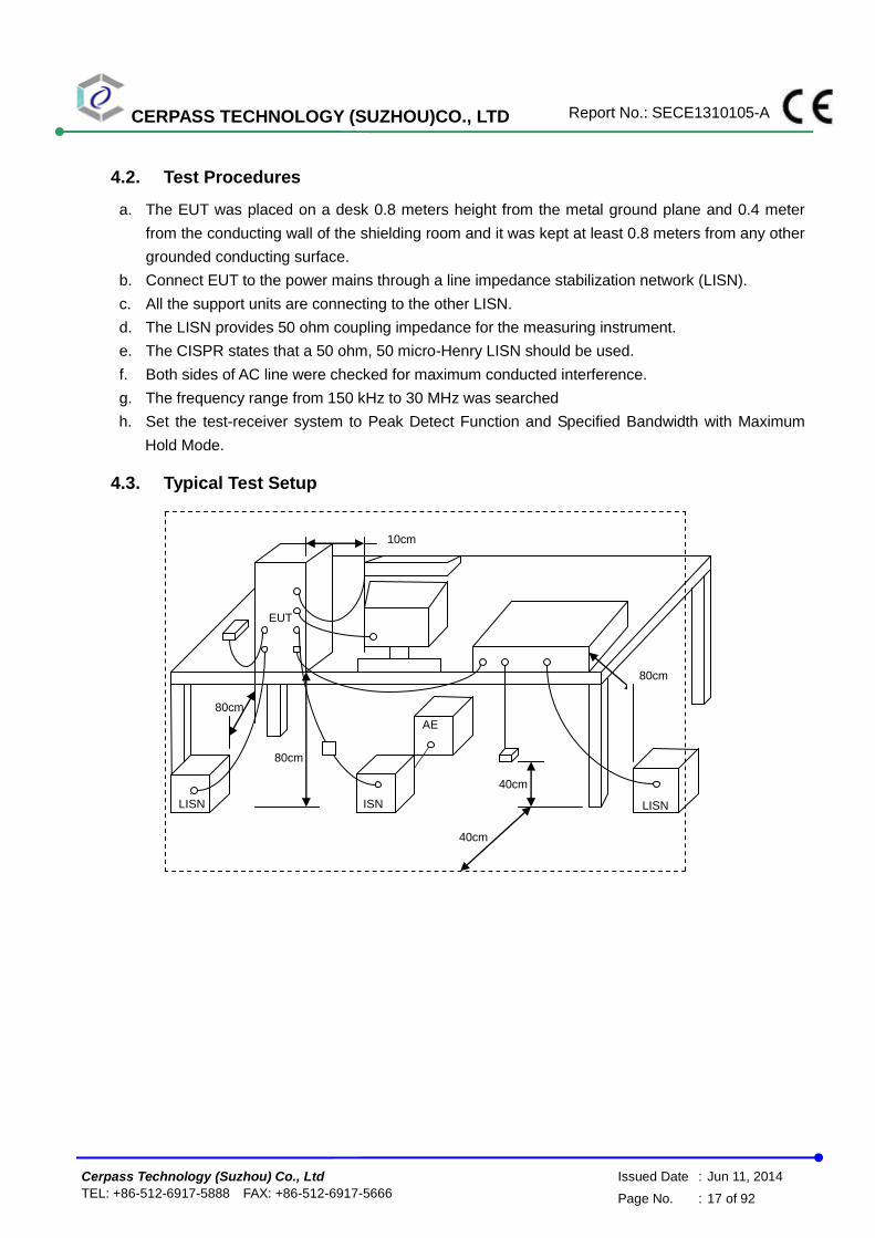
4.2. Test Procedures
a. The EUT was placed on a desk 0.8 meters height from the metal ground plane and 0.4 meter
from the conducting wall of the shielding room and it was kept at least 0.8 meters from any other
grounded conducting surface.
b. Connect EUT to the power mains through a line impedance stabilization network (LISN).
c. All the support units are connecting to the other LISN.
d. The LISN provides 50 ohm coupling impedance for the measuring instrument.
e. The CISPR states that a 50 ohm, 50 micro-Henry LISN should be used.
f. Both sides of AC line were checked for maximum conducted interference.
g. The frequency range from 150 kHz to 30 MHz was searched
h. Set the test-receiver system to Peak Detect Function and Specified Bandwidth with Maximum
Hold Mode.
4.3. Typical Test Setup
10cm
80cm
EUT
80cm
40cm
LISN
80cm
40cm
LISN ISN
AE
CERPASS TECHNOLOGY (SUZHOU)CO., LTD Report No.: SECE1310105-A
Cerpass Technology (Suzhou) Co., Ltd Issued Date : Jun 11, 2014
TEL: +86-512-6917-5888 FAX: +86-512-6917-5666 Page No. : 18 of 92
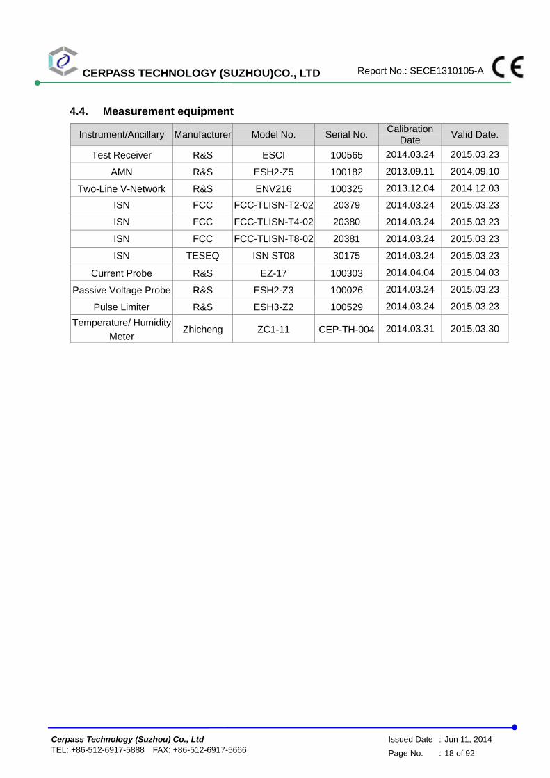
4.4. Measurement equipment
Instrument/Ancillary Manufacturer Model No. Serial No. Calibration
Date Valid Date.
Test Receiver R&S ESCI 100565 2014.03.24 2015.03.23
AMN R&S ESH2-Z5 100182 2013.09.11 2014.09.10
Two-Line V-Network R&S ENV216 100325 2013.12.04 2014.12.03
ISN FCC FCC-TLISN-T2-02 20379 2014.03.24 2015.03.23
ISN FCC FCC-TLISN-T4-02 20380 2014.03.24 2015.03.23
ISN FCC FCC-TLISN-T8-02 20381 2014.03.24 2015.03.23
ISN TESEQ ISN ST08 30175 2014.03.24 2015.03.23
Current Probe R&S EZ-17 100303 2014.04.04 2015.04.03
Passive Voltage Probe R&S ESH2-Z3 100026 2014.03.24 2015.03.23
Pulse Limiter R&S ESH3-Z2 100529 2014.03.24 2015.03.23
Temperature/ Humidity
Meter Zhicheng ZC1-11 CEP-TH-004 2014.03.31 2015.03.30

CERPASS TECHNOLOGY (SUZHOU)CO., LTD Report No.: SECE1310105-A
Cerpass Technology (Suzhou) Co., Ltd Issued Date : Jun 11, 2014
TEL: +86-512-6917-5888 FAX: +86-512-6917-5666 Page No. : 19 of 92
4.5. Test Result and Data
Test Mode : Mode 1: Full System with DVI(1920*1200@60Hz) and HDMI
(1920*1200@60Hz) with Status 1
AC Power : AC 230V/50Hz Phase : LINE
Temperature : 24℃ Humidity : 42%
Pressure(mbar) : 1002 Date : 2014/06/08
No. Frequency
(MHz)
Factor
(dB)
Reading
(dBuV)
Level
(dBuV)
Limit
(dBuV)
Margin
(dB)
Detector
1 0.4940 10.16 32.78 42.94 56.10 -13.16 QP
2 0.4940 10.16 11.98 22.14 46.10 -23.96 AVG
3 0.6980 10.15 31.74 41.89 56.00 -14.11 QP
4 0.6980 10.15 5.60 15.75 46.00 -30.25 AVG
5 0.9460 10.16 19.65 29.81 56.00 -26.19 QP
6 0.9460 10.16 -0.63 9.53 46.00 -36.47 AVG
7 1.6700 10.17 21.27 31.44 56.00 -24.56 QP
8 1.6700 10.17 0.00 10.17 46.00 -35.83 AVG
9 1.8860 10.17 31.13 41.30 56.00 -14.70 QP
10 1.8860 10.17 7.28 17.45 46.00 -28.55 AVG
11 5.2700 10.24 29.82 40.06 60.00 -19.94 QP
12 5.2700 10.24 4.65 14.89 50.00 -35.11 AVG
13 8.7260 10.26 34.81 45.07 60.00 -14.93 QP
14 8.7260 10.26 18.22 28.48 50.00 -21.52 AVG
Note: Measurement Level = Reading Level + Correct Factor

CERPASS TECHNOLOGY (SUZHOU)CO., LTD Report No.: SECE1310105-A
Cerpass Technology (Suzhou) Co., Ltd Issued Date : Jun 11, 2014
TEL: +86-512-6917-5888 FAX: +86-512-6917-5666 Page No. : 20 of 92
Test Mode : Mode 1: Full System with DVI(1920*1200@60Hz) and HDMI
(1920*1200@60Hz) with Status 1
AC Power : AC 230V/50Hz Phase : NEUTRAL
Temperature : 24℃ Humidity : 42%
Pressure(mbar) : 1002 Date : 2014/06/08
No. Frequency
(MHz)
Factor
(dB)
Reading
(dBuV)
Level
(dBuV)
Limit
(dBuV)
Margin
(dB)
Detector
1 0.1900 10.12 37.61 47.73 64.03 -16.30 QP
2 0.1900 10.12 24.83 34.95 54.03 -19.08 AVG
3 0.8700 10.15 25.34 35.49 56.00 -20.51 QP
4 0.8700 10.15 1.17 11.32 46.00 -34.68 AVG
5 1.0980 10.16 31.55 41.71 56.00 -14.29 QP
6 1.0980 10.16 8.06 18.22 46.00 -27.78 AVG
7 1.2900 10.16 35.06 45.22 56.00 -10.78 QP
8 1.2900 10.16 7.20 17.36 46.00 -28.64 AVG
9 1.8860 10.17 34.39 44.56 56.00 -11.44 QP
10 1.8860 10.17 6.89 17.06 46.00 -28.94 AVG
11 2.0900 10.17 33.63 43.80 56.00 -12.20 QP
12 2.0900 10.17 13.48 23.65 46.00 -22.35 AVG
13 4.1060 10.21 35.72 45.93 56.00 -10.07 QP
14 4.1060 10.21 17.05 27.26 46.00 -18.74 AVG
15 4.6700 10.22 24.59 34.81 56.00 -21.19 QP
16 4.6700 10.22 1.76 11.98 46.00 -34.02 AVG
CERPASS TECHNOLOGY (SUZHOU)CO., LTD Report No.: SECE1310105-A
Cerpass Technology (Suzhou) Co., Ltd Issued Date : Jun 11, 2014
TEL: +86-512-6917-5888 FAX: +86-512-6917-5666 Page No. : 21 of 92
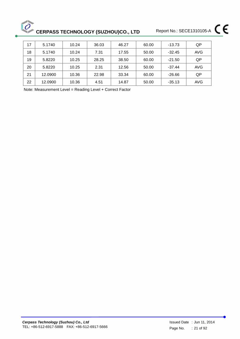
17 5.1740 10.24 36.03 46.27 60.00 -13.73 QP
18 5.1740 10.24 7.31 17.55 50.00 -32.45 AVG
19 5.8220 10.25 28.25 38.50 60.00 -21.50 QP
20 5.8220 10.25 2.31 12.56 50.00 -37.44 AVG
21 12.0900 10.36 22.98 33.34 60.00 -26.66 QP
22 12.0900 10.36 4.51 14.87 50.00 -35.13 AVG
Note: Measurement Level = Reading Level + Correct Factor

CERPASS TECHNOLOGY (SUZHOU)CO., LTD Report No.: SECE1310105-A
Cerpass Technology (Suzhou) Co., Ltd Issued Date : Jun 11, 2014
TEL: +86-512-6917-5888 FAX: +86-512-6917-5666 Page No. : 22 of 92
Test Mode : Mode 1: Full System with DVI(1920*1200@60Hz) and HDMI
(1920*1200@60Hz) with Status 1
AC Power : AC 230V/50Hz Phase : 10M
Temperature : 24℃ Humidity : 42%
Pressure(mbar) : 1002 Date : 2014/06/08
No. Frequency
(MHz)
Factor
(dB)
Reading
(dBuV)
Level
(dBuV)
Limit
(dBuV)
Margin
(dB)
Detector
1 0.4940 9.77 40.68 50.45 74.17 -23.72 QP
2 0.4940 9.77 14.15 23.92 64.17 -40.25 AVG
3 0.6980 9.77 38.50 48.27 74.00 -25.73 QP
4 0.6980 9.77 15.89 25.66 64.00 -38.34 AVG
5 0.8940 9.76 39.43 49.19 74.00 -24.81 QP
6 0.8940 9.76 14.25 24.01 64.00 -39.99 AVG
7 1.0940 9.76 36.68 46.44 74.00 -27.56 QP
8 1.0940 9.76 10.50 20.26 64.00 -43.74 AVG
9 9.7380 9.88 21.66 31.54 74.00 -42.46 QP
10 9.7380 9.88 5.12 15.00 64.00 -49.00 AVG
11 12.0980 9.86 21.68 31.54 74.00 -42.46 QP
12 12.0980 9.86 7.20 17.06 64.00 -46.94 AVG
Note: Measurement Level = Reading Level + Correct Factor

CERPASS TECHNOLOGY (SUZHOU)CO., LTD Report No.: SECE1310105-A
Cerpass Technology (Suzhou) Co., Ltd Issued Date : Jun 11, 2014
TEL: +86-512-6917-5888 FAX: +86-512-6917-5666 Page No. : 23 of 92
Test Mode : Mode 1: Full System with DVI(1920*1200@60Hz) and HDMI
(1920*1200@60Hz) with Status 1
AC Power : AC 230V/50Hz Phase : 100M
Temperature : 24℃ Humidity : 42%
Pressure(mbar) : 1002 Date : 2014/06/08
No. Frequency
(MHz)
Factor
(dB)
Reading
(dBuV)
Level
(dBuV)
Limit
(dBuV)
Margin
(dB)
Detector
1 13.4180 9.84 46.71 56.55 74.00 -17.45 QP
2 13.4180 9.84 44.88 54.72 64.00 -9.28 AVG
3 16.2260 9.82 48.53 58.35 74.00 -15.65 QP
4 16.2260 9.82 46.93 56.75 64.00 -7.25 AVG
5 18.2420 9.84 49.99 59.83 74.00 -14.17 QP
6 18.2420 9.84 47.25 57.09 64.00 -6.91 AVG
7 20.2580 9.86 49.03 58.89 74.00 -15.11 QP
8 20.2580 9.86 47.56 57.42 64.00 -6.58 AVG
9 21.6620 9.85 49.17 59.02 74.00 -14.98 QP
10 21.6620 9.85 47.64 57.49 64.00 -6.51 AVG
11 23.1299 9.84 50.34 60.18 74.00 -13.82 QP
12 23.1299 9.84 47.59 57.43 64.00 -6.57 AVG
Note: Measurement Level = Reading Level + Correct Factor

CERPASS TECHNOLOGY (SUZHOU)CO., LTD Report No.: SECE1310105-A
Cerpass Technology (Suzhou) Co., Ltd Issued Date : Jun 11, 2014
TEL: +86-512-6917-5888 FAX: +86-512-6917-5666 Page No. : 24 of 92
Test Mode : Mode 1: Full System with DVI(1920*1200@60Hz) and HDMI
(1920*1200@60Hz) with Status 1
AC Power : AC 230V/50Hz Phase : 1000M
Temperature : 24℃ Humidity : 42%
Pressure(mbar) : 1002 Date : 2014/06/08
No. Frequency
(MHz)
Factor
(dB)
Reading
(dBuV)
Level
(dBuV)
Limit
(dBuV)
Margin
(dB)
Detector
1 0.2060 9.77 41.46 51.23 82.40 -31.17 QP
2 0.2060 9.77 31.54 41.31 72.40 -31.09 AVG
3 0.9660 9.48 40.88 50.36 74.00 -23.64 QP
4 0.9660 9.48 30.83 40.31 64.00 -23.69 AVG
5 6.3418 9.47 30.41 39.88 74.00 -34.12 QP
6 6.3418 9.47 24.93 35.40 64.00 -28.60 AVG
7 13.4739 9.46 27.25 36.71 74.00 -37.29 QP
8 13.4739 9.46 21.47 30.93 64.00 -33.07 AVG
9 18.0899 9.52 28.46 37.98 74.00 -36.02 QP
10 18.0899 9.52 12.79 22.31 64.00 -41.69 AVG
11 28.9700 9.75 26.56 36.31 74.00 -37.69 QP
12 28.9700 9.75 14.86 24.61 64.00 -39.39 AVG
Note: Measurement Level = Reading Level + Correct Factor
Test engineer:
CERPASS TECHNOLOGY (SUZHOU)CO., LTD Report No.: SECE1310105-A
Cerpass Technology (Suzhou) Co., Ltd Issued Date : Jun 11, 2014
TEL: +86-512-6917-5888 FAX: +86-512-6917-5666 Page No. : 25 of 92
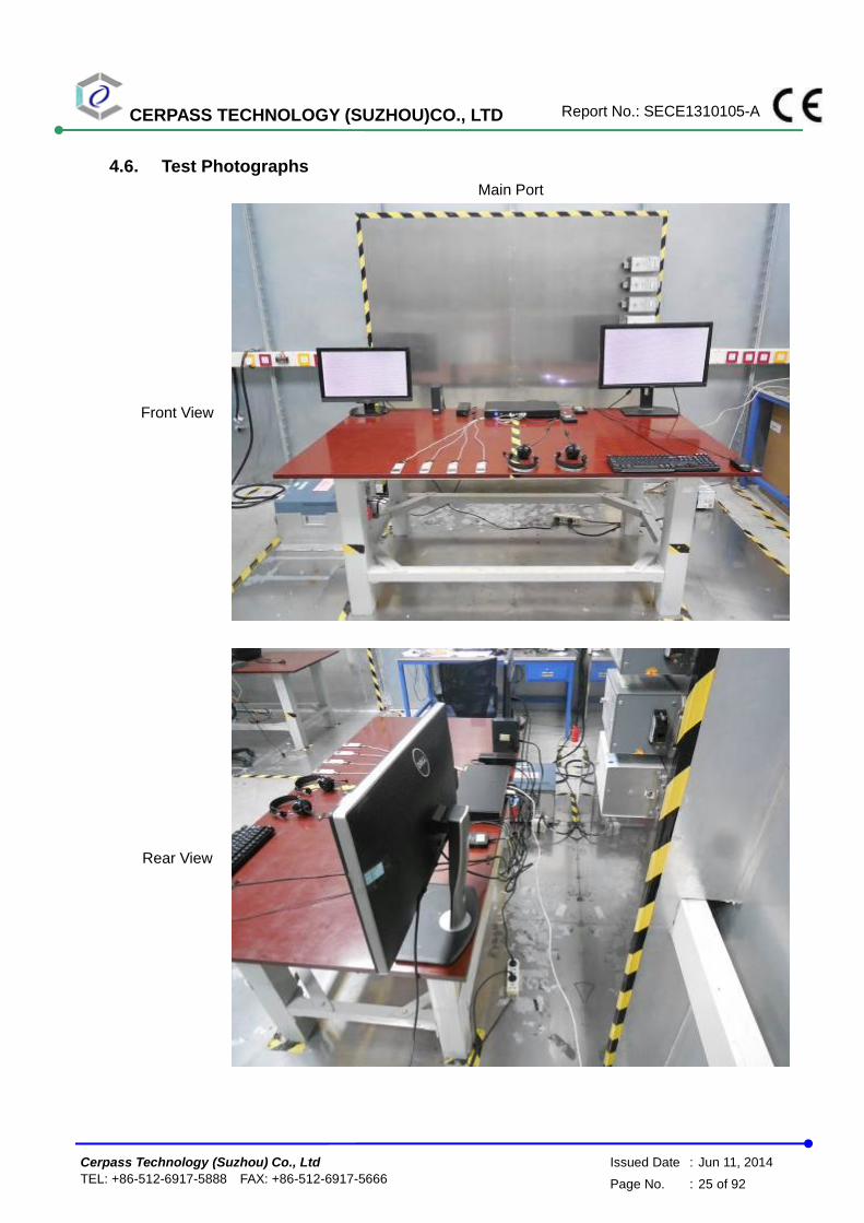
4.6. Test Photographs
Main Port
Front View
Rear View

CERPASS TECHNOLOGY (SUZHOU)CO., LTD Report No.: SECE1310105-A
Cerpass Technology (Suzhou) Co., Ltd Issued Date : Jun 11, 2014
TEL: +86-512-6917-5888 FAX: +86-512-6917-5666 Page No. : 26 of 92
LAN Port(10&100Mbps)
Front View
Rear View

CERPASS TECHNOLOGY (SUZHOU)CO., LTD Report No.: SECE1310105-A
Cerpass Technology (Suzhou) Co., Ltd Issued Date : Jun 11, 2014
TEL: +86-512-6917-5888 FAX: +86-512-6917-5666 Page No. : 27 of 92
LAN Port(1000Mbps)
Front View
Rear View

CERPASS TECHNOLOGY (SUZHOU)CO., LTD Report No.: SECE1310105-A
Cerpass Technology (Suzhou) Co., Ltd Issued Date : Jun 11, 2014
TEL: +86-512-6917-5888 FAX: +86-512-6917-5666 Page No. : 28 of 92
5. Test of Radiated Emission
5.1. Test Limit
The EUT shall meet the limits of below Table when measured at the measuring distance R in
accordance with the methods described in European Standard EN 55022. If the reading on the
measuring receiver shows fluctuations close to the limit, the reading shall be observed for at least
15 s at each measurement frequency; the highest reading shall be recorded, with the exception of
any brief isolated high reading, which shall be ignored.
Table – Limits for radiated disturbance of class B ITE at a measuring distance of 10 m
Frequency range
MHz
Quasi-peak limits
dB(V/m)
30 to 230 30
230 to 1000 37
NOTE 1 The lower limit shall apply at the transition frequency.
NOTE 2 Additional provisions may be required for cases where interference occurs.
The EUT shall meet the limits of below Table when measured in accordance with the method
described in European Standard EN 55022 and the conditional testing procedure described below.
Table – Limits for radiated disturbance of class B ITE at a measuring distance of 3 m
Frequency range
GHz
Average limit
dB(V/m)
Peak limits
dB(V/m)
1 to 3 50 70
3 to 6 54 74
NOTE The lower limit applies at the transition frequency.
• Conditional testing procedure:
The highest internal source of an EUT is defined as the highest frequency generated or used
within the EUT or on which the EUT operates or tunes.
If the highest frequency of the internal sources of the EUT is less than 108 MHz, the measurement
shall only be made up to 1 GHz.
If the highest frequency of the internal sources of the EUT is between 108 MHz and 500 MHz, the
measurement shall only be made up to 2 GHz.
If the highest frequency of the internal sources of the EUT is between 500 MHz and 1 GHz, the
measurement shall only be made up to 5 GHz.
If the highest frequency of the internal sources of the EUT is above 1 GHz, the measurement shall
be made up to 5 times the highest frequency or 6 GHz, whichever is less.

CERPASS TECHNOLOGY (SUZHOU)CO., LTD Report No.: SECE1310105-A
Cerpass Technology (Suzhou) Co., Ltd Issued Date : Jun 11, 2014
TEL: +86-512-6917-5888 FAX: +86-512-6917-5666 Page No. : 29 of 92
5.2. Test Procedures
a. The EUT was placed on a relatable table top 0.8 meter above ground.
b. The EUT was set 10 meters from the interference receiving antenna which was mounted
on the top of a variable height antenna tower.
c. The table was rotated 360 degrees to determine the position of the highest radiation.
d. The antenna is a half wave dipole and its height is varied between one meter and four
meters above ground to find the maximum value of the field strength both horizontal
polarization and vertical polarization of the antenna are set to make the measurement.
e. For each suspected emission the EUT was arranged to its worst case and then tune the
antenna tower (from 1 M to 4 M) and turn table (from 0 degree to 360 degrees) to find the
maximum reading.
f. Set the test-receiver system to Peak Detect Function and specified bandwidth with
Maximum Hold Mode.
g. If the emission level of the EUT in peak mode was 3 dB lower than the limit specified, then
testing will be stopped and peak values of EUT will be reported, otherwise, the emissions
which do not have 3 dB margin will be repeated one by one using the quasi-peak method
and reported.

CERPASS TECHNOLOGY (SUZHOU)CO., LTD Report No.: SECE1310105-A
Cerpass Technology (Suzhou) Co., Ltd Issued Date : Jun 11, 2014
TEL: +86-512-6917-5888 FAX: +86-512-6917-5666 Page No. : 30 of 92
5.3. Typical test Setup
Below 1GHz Test Setup
Above 1GHz Test Setup

CERPASS TECHNOLOGY (SUZHOU)CO., LTD Report No.: SECE1310105-A
Cerpass Technology (Suzhou) Co., Ltd Issued Date : Jun 11, 2014
TEL: +86-512-6917-5888 FAX: +86-512-6917-5666 Page No. : 31 of 92
5.4. Measurement equipment
Instrument/Ancillary Manufacturer Model No. Serial No. Calibration
Date Valid Date.
EMI Test Receiver R&S ESCI 101183 2014.03.24 2015.03.23
Preamplifier Agilent 87405B My39500554 2014.03.24 2015.03.23
Preamplifier Agilent 8449B 3008A02342 2014.03.24 2015.03.23
Bilog Antenna Schaffner CBL6141A 4257 2014.05.24 2015.05.23
Broad-Band Horn
Antenna Schwarzbeck BBHA9120D 9120D-618 2014.05.24 2015.05.23
Spectrum Analyzer R&S FSP40 100324 2014.03.24 2015.03.23
Temperature/ Humidity
Meter Zhicheng ZC1-11 CEP-TH-001 2014.03.31 2015.03.30

CERPASS TECHNOLOGY (SUZHOU)CO., LTD Report No.: SECE1310105-A
Cerpass Technology (Suzhou) Co., Ltd Issued Date : Jun 11, 2014
TEL: +86-512-6917-5888 FAX: +86-512-6917-5666 Page No. : 32 of 92
5.5. Test Result and Data (30MHz ~ 1000MHz)
Test Mode : Mode 1: Full System with DVI(1920*1200@60Hz) and HDMI (1920*1200@60Hz) with Status 1
AC Power : AC 230V/50Hz Ant. Polarization: Horizontal
Temp : 24℃ Humidity : 42%
Pressure(mbar) : 1002 Date : 2014/06/01
No. Frequency
(MHz)
Factor
(dB/m)
Reading
(dBuV)
Level
(dBuV/m)
Limit
(dBuV/m)
Margin
(dB)
Det. Height
(cm)
Azimuth
(deg)
1 95.9599 -13.77 35.97 22.20 30.00 -7.80 QP 400 273
2 207.5099 -10.80 34.49 23.69 30.00 -6.31 QP 400 9
3 346.2200 -5.35 35.72 30.37 37.00 -6.63 QP 400 234
4 445.1600 -5.44 35.81 30.37 37.00 -6.63 QP 400 61
5 593.5700 -1.22 31.55 30.33 37.00 -6.67 QP 100 136
6 890.3899 2.17 28.00 30.17 37.00 -6.83 QP 100 71
Note: Measurement Level = Reading Level + Correct Factor

CERPASS TECHNOLOGY (SUZHOU)CO., LTD Report No.: SECE1310105-A
Cerpass Technology (Suzhou) Co., Ltd Issued Date : Jun 11, 2014
TEL: +86-512-6917-5888 FAX: +86-512-6917-5666 Page No. : 33 of 92
Test Mode : Mode 1: Full System with DVI(1920*1200@60Hz) and HDMI
(1920*1200@60Hz) with Status 1
AC Power : AC 230V/50Hz Ant. Polarization: Vertical
Temp : 24℃ Humidity : 42%
Pressure(mbar) : 1002 Date : 2014/06/01
No. Frequency
(MHz)
Factor
(dB/m)
Reading
(dBuV)
Level
(dBuV/m)
Limit
(dBuV/m)
Margin
(dB)
Det. Height
(cm)
Azimuth
(deg)
1 31.9400 -6.02 27.65 21.63 30.00 -8.37 QP 100 155
2 64.9200 -14.13 37.11 22.98 30.00 -7.02 QP 400 263
3 135.7300 -9.83 32.87 23.04 30.00 -6.96 QP 100 19
4 181.3200 -12.48 36.07 23.59 30.00 -6.41 QP 100 190
5 279.2900 -9.06 36.33 27.27 37.00 -9.73 QP 100 0
6 355.9200 -5.00 34.90 29.90 37.00 -7.10 QP 100 71
Note: Measurement Level = Reading Level + Correct Factor

CERPASS TECHNOLOGY (SUZHOU)CO., LTD Report No.: SECE1310105-A
Cerpass Technology (Suzhou) Co., Ltd Issued Date : Jun 11, 2014
TEL: +86-512-6917-5888 FAX: +86-512-6917-5666 Page No. : 34 of 92
5.6. Test Result and Data (1000MHz ~ 6000MHz)
Test Mode : Mode 1: Full System with DVI(1920*1200@60Hz) and HDMI (1920*1200@60Hz) with Status 1
AC Power : AC 230V/50Hz Ant. Polarization: Horizontal
Temp : 24℃ Humidity : 42%
Pressure(mbar) : 1002 Date : 2014/06/01
No. Frequency
(MHz)
Factor
(dB/m)
Reading
(dBuV)
Level
(dBuV/m)
Limit
(dBuV/m)
Margin
(dB)
Det. Height
(cm)
Azimuth
(deg)
1 1035.000 -15.36 61.50 46.14 70.00 -23.86 peak 100 33
2 1335.000 -13.11 58.68 45.57 70.00 -24.43 peak 100 76
3 1550.000 -12.18 56.47 44.29 70.00 -25.71 peak 100 61
4 2075.000 -7.39 54.09 46.70 70.00 -23.30 peak 100 358
5 2375.000 -3.18 51.08 47.90 70.00 -22.10 peak 100 72
6 2520.000 -3.99 49.08 45.09 70.00 -24.91 peak 100 42
Note: Measurement Level = Reading Level + Correct Factor

CERPASS TECHNOLOGY (SUZHOU)CO., LTD Report No.: SECE1310105-A
Cerpass Technology (Suzhou) Co., Ltd Issued Date : Jun 11, 2014
TEL: +86-512-6917-5888 FAX: +86-512-6917-5666 Page No. : 35 of 92
Test Mode : Mode 1: Full System with DVI(1920*1200@60Hz) and HDMI
(1920*1200@60Hz) with Status 1
AC Power : AC 230V/50Hz Ant. Polarization: Vertical
Temp : 24℃ Humidity : 42%
Pressure(mbar) : 1002 Date : 2014/06/01
No. Frequency
(MHz)
Factor
(dB/m)
Reading
(dBuV)
Level
(dBuV/m)
Limit
(dBuV/m)
Margin
(dB)
Det. Height
(cm)
Azimuth
(deg)
1 1060.000 -15.25 62.31 47.06 70.00 -22.94 peak 100 342
2 1335.000 -13.11 61.89 48.78 70.00 -21.22 peak 100 239
3 1595.000 -12.02 59.11 47.09 70.00 -22.91 peak 100 313
4 1860.000 -10.13 56.55 46.42 70.00 -23.58 peak 100 298
5 2075.000 -7.39 54.39 47.00 70.00 -23.00 peak 100 33
6 2375.000 -3.18 50.45 47.27 70.00 -22.73 peak 100 56
Note: Measurement Level = Reading Level + Correct Factor
Test engineer:

CERPASS TECHNOLOGY (SUZHOU)CO., LTD Report No.: SECE1310105-A
Cerpass Technology (Suzhou) Co., Ltd Issued Date : Jun 11, 2014
TEL: +86-512-6917-5888 FAX: +86-512-6917-5666 Page No. : 36 of 92
5.7. Test Photographs (30MHz ~ 1000MHz)
Front View
Rear View

CERPASS TECHNOLOGY (SUZHOU)CO., LTD Report No.: SECE1310105-A
Cerpass Technology (Suzhou) Co., Ltd Issued Date : Jun 11, 2014
TEL: +86-512-6917-5888 FAX: +86-512-6917-5666 Page No. : 37 of 92
5.8. Test Photographs (1000MHz ~ 6000MHz)
Front View
Rear View

CERPASS TECHNOLOGY (SUZHOU)CO., LTD Report No.: SECE1310105-A
Cerpass Technology (Suzhou) Co., Ltd Issued Date : Jun 11, 2014
TEL: +86-512-6917-5888 FAX: +86-512-6917-5666 Page No. : 38 of 92
6. Harmonics Test
6.1. Limits Of Harmonics Current Measurement
Limits for Class A equipment
Harmonics Order n
Max. permissible harmonics current
A
Harmonics Order n
Max. permissible harmonics current
A
Odd harmonics Even harmonics
3 2.30 2 1.08
5 1.14 4 0.43
7 0.77 6 0.30
9 0.40 8<=n<=40 0.23x8/n
11 0.33
13 0.21
15<=n<=39 0.15x15/n
(b) Limits for Class B equipment For Class B equipment, the harmonics of the input current shall not exceed the values given in Table that is the limit of Class A multiplied by a factor of 1,5. (c) Limits for Class C equipment
Harmonics Order n
Maximum permissible harmonic current expressed as a percentage of the input current at the fundamental frequency
℅
2 2
3 30.λ*
5 10
7 7
9 5
11<n<39
(odd harmonics only) 3
* λ is the circuit power factor
(d) Limits for Class D equipment
Harmonics Order n
Maximum permissible harmonic current per watt
mA/W
Maximum permissible harmonic current
A
3 3.4 2.30
5 1.9 1.14
7 1.0 0.77
9 0.5 0.40
11 0.35 0.33
11 < n < 39 (odd harmonics only)
3.85/n See limit of Class A
NOTE: According to section 7 of EN 61000-3-2, the above limits for all equipment except for lighting equipment having an active input power > 75 W and no limits apply for equipment with an active input power up to and including 75 W.

CERPASS TECHNOLOGY (SUZHOU)CO., LTD Report No.: SECE1310105-A
Cerpass Technology (Suzhou) Co., Ltd Issued Date : Jun 11, 2014
TEL: +86-512-6917-5888 FAX: +86-512-6917-5666 Page No. : 39 of 92
6.2. Measurement equipment
Instrument/Ancillary Manufacturer Model No. Serial No. Calibration
Date Valid Date.
EMC Emission Tester EMCPARTNE
R Harmonics-1000 159 2014.03.24 2015.03.23
Temperature/ Humidity Meter
Zhicheng ZC1-11 CEP-TH-004 2014.03.31 2015.03.30

CERPASS TECHNOLOGY (SUZHOU)CO., LTD Report No.: SECE1310105-A
Cerpass Technology (Suzhou) Co., Ltd Issued Date : Jun 11, 2014
TEL: +86-512-6917-5888 FAX: +86-512-6917-5666 Page No. : 40 of 92
6.3. Test Result and Data
Basic Standard : EN 61000-3-2
Final Test Result : PASS
Test Mode : Mode 1
Temperature : 20℃
Humidity : 50 %
Atmospheric Pressure : 100 kPa
Test Date : Jun 04, 2014
Full Bar : Actual Values
Empty Bar : Maximum Values
Blue : Current , Green : Voltage , Red : Failed
Urms = 231.1V Freq = 50.000 Range: 1 A
Irms = 0.342A Ipk = 0.836A cf = 2.442
P = 48.67W S = 79.10VA pf = 0.615
THDi = 60.2 % THDu = 0.90 % Class D
Test - Time : 15min ( 100 %)
Limit Reference: Pmax = 50.122W
Test completed, Result: PASSED

CERPASS TECHNOLOGY (SUZHOU)CO., LTD Report No.: SECE1310105-A
Cerpass Technology (Suzhou) Co., Ltd Issued Date : Jun 11, 2014
TEL: +86-512-6917-5888 FAX: +86-512-6917-5666 Page No. : 41 of 92
Order Freq. Irms Irms%L Imax Imax%L Limit Status [Hz] [A] [%] [A] [%] [A] 1 50 0.2321 0.2459 2 100 0.1396 0.1442 3 150 0.0794 46.596 0.0882 51.753 0.1704 4 200 0.0289 0.0375 5 250 0.0242 25.380 0.0291 30.571 0.0952 6 300 0.0284 0.0340 7 350 0.0221 44.082 0.0255 50.901 0.0501 8 400 0.0179 0.0213 9 450 0.0162 64.540 0.0187 74.768 0.0251 10 500 0.0148 0.0168 11 550 0.0128 72.716 0.0152 86.633 0.0175 12 600 0.0112 0.0136 13 650 0.0113 76.068 0.0129 86.759 0.0148 14 700 0.0103 0.0117 15 750 0.0085 66.422 0.0103 79.706 0.0129 16 800 0.0079 0.0093 17 850 0.0078 68.825 0.0088 77.429 0.0114 18 900 0.0074 0.0086 19 950 0.0071 69.711 0.0078 76.321 0.0102 20 1000 0.0064 0.0075 21 1050 0.0059 64.429 0.0071 77.713 0.0092 22 1100 0.0058 0.0068 23 1150 0.0059 69.837 0.0064 76.385 0.0084 24 1200 0.0055 0.0062 25 1250 0.0051 66.422 0.0059 76.701 0.0077 26 1300 0.0047 0.0057 27 1350 0.0048 66.611 0.0054 76.005 0.0071 28 1400 0.0045 0.0052 29 1450 0.0046 68.794 0.0051 77.049 0.0067 30 1500 0.0042 0.0049 31 1550 0.0041 65.694 0.0048 76.480 0.0062 32 1600 0.0040 0.0046 33 1650 0.0039 66.801 0.0046 78.283 0.0058 34 1700 0.0038 0.0044 35 1750 0.0037 66.422 0.0043 77.492 0.0055 36 1800 0.0037 0.0042 37 1850 0.0034 65.536 0.0040 77.239 0.0052 38 1900 0.0033 0.0040 39 1950 0.0034 69.078 0.0038 76.480 0.0049 40 2000 0.0032 0.0037
EUT is PASSED if:
- all Average values of the Individual Harmonic Currents (Iavg)
are below 100% of the Individual Limits.
- all Maximum values of the Individual Harmonic Currents (Imax)
are below 150% of the Individual Limits.
Test engineer:
CERPASS TECHNOLOGY (SUZHOU)CO., LTD Report No.: SECE1310105-A
Cerpass Technology (Suzhou) Co., Ltd Issued Date : Jun 11, 2014
TEL: +86-512-6917-5888 FAX: +86-512-6917-5666 Page No. : 42 of 92
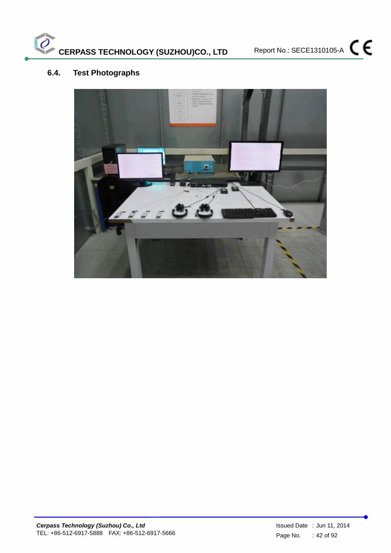
6.4. Test Photographs
CERPASS TECHNOLOGY (SUZHOU)CO., LTD Report No.: SECE1310105-A
Cerpass Technology (Suzhou) Co., Ltd Issued Date : Jun 11, 2014
TEL: +86-512-6917-5888 FAX: +86-512-6917-5666 Page No. : 43 of 92
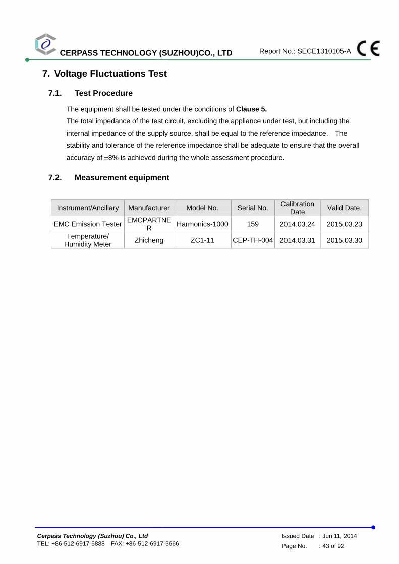
7. Voltage Fluctuations Test
7.1. Test Procedure
The equipment shall be tested under the conditions of Clause 5.
The total impedance of the test circuit, excluding the appliance under test, but including the
internal impedance of the supply source, shall be equal to the reference impedance. The
stability and tolerance of the reference impedance shall be adequate to ensure that the overall
accuracy of 8% is achieved during the whole assessment procedure.
7.2. Measurement equipment
Instrument/Ancillary Manufacturer Model No. Serial No. Calibration
Date Valid Date.
EMC Emission Tester EMCPARTNE
R Harmonics-1000 159 2014.03.24 2015.03.23
Temperature/ Humidity Meter
Zhicheng ZC1-11 CEP-TH-004 2014.03.31 2015.03.30

CERPASS TECHNOLOGY (SUZHOU)CO., LTD Report No.: SECE1310105-A
Cerpass Technology (Suzhou) Co., Ltd Issued Date : Jun 11, 2014
TEL: +86-512-6917-5888 FAX: +86-512-6917-5666 Page No. : 44 of 92
7.3. Test Result and Data
Basic Standard : EN 61000-3-3
Final Test Result : PASS
Test Mode : Mode 1: Full System with DVI(1920*1080@60Hz) and HDMI
(1920*1080@60Hz)
Temperature : 21℃
Humidity : 51 %
Atmospheric Pressure : 100 kPa
Test Date : Jun 04, 2014
Full Bar : Actual Values
Empty Bar : Maximum Values
Circles : Average Values
Blue : Current , Green : Voltage , Red : Failed
CERPASS TECHNOLOGY (SUZHOU)CO., LTD Report No.: SECE1310105-A
Cerpass Technology (Suzhou) Co., Ltd Issued Date : Jun 11, 2014
TEL: +86-512-6917-5888 FAX: +86-512-6917-5666 Page No. : 45 of 92
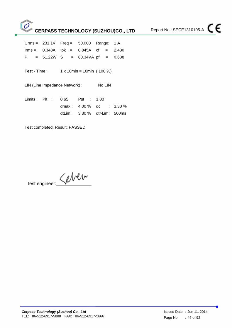
Urms = 231.1V Freq = 50.000 Range: 1 A
Irms = 0.348A Ipk = 0.845A cf = 2.430
P = 51.22W S = 80.34VA pf = 0.638
Test - Time : 1 x 10min = 10min ( 100 %)
LIN (Line Impedance Network) : No LIN
Limits : Plt : 0.65 Pst : 1.00
dmax : 4.00 % dc : 3.30 %
dtLim: 3.30 % dt>Lim: 500ms
Test completed, Result: PASSED
Test engineer:

CERPASS TECHNOLOGY (SUZHOU)CO., LTD Report No.: SECE1310105-A
Cerpass Technology (Suzhou) Co., Ltd Issued Date : Jun 11, 2014
TEL: +86-512-6917-5888 FAX: +86-512-6917-5666 Page No. : 46 of 92
7.4. Test Photographs

CERPASS TECHNOLOGY (SUZHOU)CO., LTD Report No.: SECE1310105-A
Cerpass Technology (Suzhou) Co., Ltd Issued Date : Jun 11, 2014
TEL: +86-512-6917-5888 FAX: +86-512-6917-5666 Page No. : 47 of 92
8. Electrostatic Discharge Immunity Test
8.1. Test Procedure
a. In the case of air discharge testing the climatic conditions shall be within the following ranges:
- ambient temperature: 15℃ to 35℃;
- relative humidity : 30% to 60%;
- atmospheric pressure : 86 KPa (860 hPa) to 106 KPa (1060 hPa).
b. Test programs and software shall be chosen so as to exercise all normal modes of operation of
the EUT. The use of special exercising software is encouraged, but permitted only where it
can be shown that the EUT is being comprehensively exercised.
c. The test voltage shall be increased from the minimum to the selected test severity level, in
order to determine any threshold of failure. The final severity level should not exceed the
product specification value in order to avoid damage to the equipment.
d. The test shall be performed with both air discharge and contact discharge. On reselected
points at least 10 single discharges (in the most sensitive polarity) shall be applied on air
discharge. On reselected points at least 25 single discharges (in the most sensitive polarity)
shall be applied on contact discharge.
e. For the time interval between successive single discharges an initial value of one second is
recommended. Longer intervals may be necessary to determine whether a system failure has
occurred.
f. In the case of contact discharges, the tip of the discharge electrode shall touch the EUT before
the discharge switch is operated.
g. In the case of painted surface covering a conducting substrate, the following procedure shall
be adopted :
If the coating is not declared to be an insulating coating by the equipment manufacturer,
then the pointed tip of the generator shall penetrate the coating so as to make contact with
the conducting substrate.
Coating declared as insulating by the manufacturer shall only be submitted to the air
discharge.
The contact discharge test shall not be applied to such surfaces.
h. In the case of air discharges, the round discharge tip of the discharge electrode shall be
approached as fast as possible (without causing mechanical damage) to touch the EUT . After
each discharge, the ESD generator (discharge electrode) shall be removed from the EUT. The
generator is then retriggered for a new single discharge. This procedure shall be repeated until
the discharges are completed. In the case of an air discharge test, the discharge switch, which
is used for contact discharge, shall be closed.

CERPASS TECHNOLOGY (SUZHOU)CO., LTD Report No.: SECE1310105-A
Cerpass Technology (Suzhou) Co., Ltd Issued Date : Jun 11, 2014
TEL: +86-512-6917-5888 FAX: +86-512-6917-5666 Page No. : 48 of 92
8.2. Test Setup for Tests Performed in Laboratory
The test setup consists of the test generator, EUT and auxiliary instrumentation necessary to
perform DIRECT and INDIRECT application of discharges to the EUT as applicable, in the follow
manner :
a. Contact Discharge to the conductive surfaces and to coupling plane;
b. Air Discharge at insulating surfaces.
The preferred test method is that of type tests performed in laboratories and the only accepted
method of demonstrating conformance with this standard. The EUT was arranged as closely as
possible to arrangement in final installed conditions.
A ground reference plane was provided on the floor of the test site. It was a metallic sheet (copper
or aluminum) of 0.25 mm, minimum thickness; other metallic may be used but they shall have at
least 0.65 mm thickness. In the Exclusive Certification Corp., we provided 1 mm thickness
stainless steel ground reference plane. The minimum size of the ground reference plane is 2.5 m x
2.5 m, the exact size depending on the dimensions of the EUT. It was connected to the protective
grounding system.
The EUT was arranged and connected according to its functional requirements. A distance of 1m
minimum was provided between the EUT and the wall of the lab. and any other metallic structure.
In cases where this length exceeds the length necessary to apply the discharges to the selected
points, the excess length shall, where possible, be placed non-inductively off the ground reference
plane and shall not come closer than 0.2m to other conductive parts in the test setup.
Where the EUT is installed on a metal table, the table was connected to the reference plane via a
cable with a 470k ohm resister located at each end, to prevent a build-up of charge. The test setup
CERPASS TECHNOLOGY (SUZHOU)CO., LTD Report No.: SECE1310105-A
Cerpass Technology (Suzhou) Co., Ltd Issued Date : Jun 11, 2014
TEL: +86-512-6917-5888 FAX: +86-512-6917-5666 Page No. : 49 of 92
was consist a wooden table, 0.8m high, standing on the ground reference plane. A HCP, 1.6 m x
0.8 m, was placed on the table. The EUT and cables was isolated from the HCP by an insulating
support 0.5 mm thick. The VCP size, 0.5 m x 0.5 m.
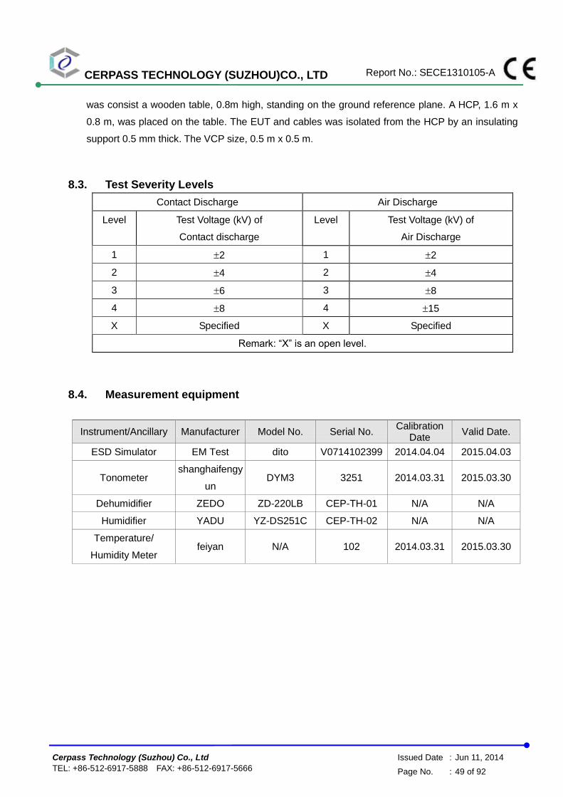
8.3. Test Severity Levels
Contact Discharge Air Discharge
Level Test Voltage (kV) of
Contact discharge
Level Test Voltage (kV) of
Air Discharge
1 2 1 2
2 4 2 4
3 6 3 8
4 8 4 15
X Specified X Specified
Remark: “X” is an open level.
8.4. Measurement equipment
Instrument/Ancillary Manufacturer Model No. Serial No. Calibration
Date Valid Date.
ESD Simulator EM Test dito V0714102399 2014.04.04 2015.04.03
Tonometer shanghaifengy
un DYM3 3251 2014.03.31 2015.03.30
Dehumidifier ZEDO ZD-220LB CEP-TH-01 N/A N/A
Humidifier YADU YZ-DS251C CEP-TH-02 N/A N/A
Temperature/
Humidity Meter feiyan N/A 102 2014.03.31 2015.03.30

CERPASS TECHNOLOGY (SUZHOU)CO., LTD Report No.: SECE1310105-A
Cerpass Technology (Suzhou) Co., Ltd Issued Date : Jun 11, 2014
TEL: +86-512-6917-5888 FAX: +86-512-6917-5666 Page No. : 50 of 92
8.5. Test Result and Data
Basic Standard : IEC 61000-4-2
Final Test Result : PASS
Pass performance criteria : B
Required performance criteria : B
Test Voltage : 2 / 4 / 8 kV for air discharge,
2 / 4 kV for contact discharge
Temperature : 20°C
Relative Humidity : 50 %
Atmospheric Pressure : 100 kPa
Test Date : Jun 11, 2014
Test Mode1 : Full System with DVI(1920*1200@60Hz) and HDMI (1920*1200@60Hz) with
Status 1
Contact Discharge Air Discharge
25 times / each 10 times / each
Voltage 2 kV 4 kV 6 kV 8 kV 2 kV 4 kV 8 kV 10 kV
Point\Polarity + - + - + - + - + - + - + - + -
HCP A A A A --- --- --- --- --- --- --- --- --- --- --- ---
VCP A A A A --- --- --- --- --- --- --- --- --- --- --- ---
1,2 A A A A --- --- --- --- --- --- --- --- --- --- --- ---
3,4,5,6,7,8,9,
10,11,12 --- --- --- --- --- --- --- --- A A A A A A --- ---
13,14,15,16,1
7,18 A A A A --- --- --- --- --- --- --- --- --- --- --- ---
19,20,21,22,2
3,24 --- --- --- --- --- --- --- --- A A A A A A --- ---
25,26,27,28,2
9 A A A A --- --- --- --- --- ---
Test engineer:

CERPASS TECHNOLOGY (SUZHOU)CO., LTD Report No.: SECE1310105-A
Cerpass Technology (Suzhou) Co., Ltd Issued Date : Jun 11, 2014
TEL: +86-512-6917-5888 FAX: +86-512-6917-5666 Page No. : 51 of 92
8.6. Test Photographs

CERPASS TECHNOLOGY (SUZHOU)CO., LTD Report No.: SECE1310105-A
Cerpass Technology (Suzhou) Co., Ltd Issued Date : Jun 11, 2014
TEL: +86-512-6917-5888 FAX: +86-512-6917-5666 Page No. : 52 of 92

CERPASS TECHNOLOGY (SUZHOU)CO., LTD Report No.: SECE1310105-A
Cerpass Technology (Suzhou) Co., Ltd Issued Date : Jun 11, 2014
TEL: +86-512-6917-5888 FAX: +86-512-6917-5666 Page No. : 53 of 92

CERPASS TECHNOLOGY (SUZHOU)CO., LTD Report No.: SECE1310105-A
Cerpass Technology (Suzhou) Co., Ltd Issued Date : Jun 11, 2014
TEL: +86-512-6917-5888 FAX: +86-512-6917-5666 Page No. : 54 of 92
9. Radio Frequency electromagnetic field immunity test
9.1. Test Procedure
a. The equipment to be tested is placed in the center of the enclosure on a wooden table. The
equipment is then connected to power and signal leads according to pertinent installation
instructions.
b. The antenna which is enabling the complete frequency range of 80-1000 MHz is placed
3m away from the equipment. The required field strength is determined by placing the field
strength meter(s) on top of or directly alongside the equipment under test and monitoring
the field strength meter via a remote field strength indicator outside the enclosure while
adjusting the continuous-wave to the applicable antennae.
c. The test is normally performed with the antenna facing the most sensitive side of the EUT.
The polarization of the field generated by the bucolical antenna necessitates testing each
position twice, once with the antenna positioned vertically and again with the antenna
positioned horizontally. The circular polarization of the field from the log-spiral antenna
makes a change of position of the antenna unnecessary.
d. At each of the above conditions, the frequency range is swept 80-1000 MHz, pausing to
adjust the R.F. signal level or to switch oscillators and antenna. The rate of sweep is in the
order of 1.5*10-3 decades/s. The sensitive frequencies or frequencies of dominant interest
may be discretely analyzed.

CERPASS TECHNOLOGY (SUZHOU)CO., LTD Report No.: SECE1310105-A
Cerpass Technology (Suzhou) Co., Ltd Issued Date : Jun 11, 2014
TEL: +86-512-6917-5888 FAX: +86-512-6917-5666 Page No. : 55 of 92
9.2. Test Severity Levels
Frequency Band
Level Test field strength (V/m)
1 1
2 3
3 10
X Specified
Remark: “X” is an open class.
9.3. Measurement equipment
Instrument/Ancillary Manufacturer Model No. Serial No. Calibration
Date Valid Date.
Signal Generator R&S SML03 103287 2014.03.24 2015.03.23
Power Sensor R&S NR P-Z91 100383 2014.03.24 2015.03.23
Power Sensor R&S NRP-Z91 100384 2014.03.24 2015.03.23
Power Meter R&S NRP 101206 2014.03.24 2015.03.23
Power Amplifer BONN BLWA0830-16
0/100/40D 076659 2014.03.24 2015.03.23
Istropic Electric Field
Probe
EST.LINDGRE
N HI-6105 137445 2013.09.03 2014.09.02
EMS Antenna R&S HL046E 100028 N/A N/A
Temperature/
Humidity Meter feiyan N/A 101 2014.03.31 2015.03.30

CERPASS TECHNOLOGY (SUZHOU)CO., LTD Report No.: SECE1310105-A
Cerpass Technology (Suzhou) Co., Ltd Issued Date : Jun 11, 2014
TEL: +86-512-6917-5888 FAX: +86-512-6917-5666 Page No. : 56 of 92
9.4. Test Result and Data
Basic Standard : IEC 61000-4-3
Final Test Result : PASS
Pass performance criteria : A
Required performance criteria : A
Frequency Range : 80~1000 MHz
Temperature : 18°C
Relative Humidity : 50%
Atmospheric Pressure : 100 kPa
Test Date : Jun 10, 2014
Mode 1: Full System with DVI(1920*1200@60Hz) and HDMI (1920*1200@60Hz) with Status 1
Modulation : AM 80% , 1KHz sine wave , Dwell time: 3.0 S
Frequency Step Size : 1 % of preceding frequency value
Frequency (MHz) Antenna Polarization face Field strength (V/m) Result
80~1000 Vertical Front 3 V/m A
80~1000 Vertical Rear 3 V/m A
80~1000 Vertical Left 3 V/m A
80~1000 Vertical Right 3 V/m A
80~1000 Horizontal Front 3 V/m A
80~1000 Horizontal Rear 3 V/m A
80~1000 Horizontal Left 3 V/m A
80~1000 Horizontal Right 3 V/m A
Test engineer:

CERPASS TECHNOLOGY (SUZHOU)CO., LTD Report No.: SECE1310105-A
Cerpass Technology (Suzhou) Co., Ltd Issued Date : Jun 11, 2014
TEL: +86-512-6917-5888 FAX: +86-512-6917-5666 Page No. : 57 of 92
9.5. Test Photographs

CERPASS TECHNOLOGY (SUZHOU)CO., LTD Report No.: SECE1310105-A
Cerpass Technology (Suzhou) Co., Ltd Issued Date : Jun 11, 2014
TEL: +86-512-6917-5888 FAX: +86-512-6917-5666 Page No. : 58 of 92
10. Electrical Fast Transient/ Burst Immunity Test
10.1. Test Procedure
a. In order to minimize the effect of environmental parameters on test results, the climatic
conditions when test is carrying out shall comply with the following requirements:
ambient temperature: 15℃ to 35℃;
relative humidity : 45% to 75%;
Atmospheric pressure: 86 Kpa (860 mbar) to 106 Kpa (1060 mbar).
b. In order to minimize the effect of environmental parameters on test results, the electromagnetic
environment of the laboratory shall not influence the test results.
c. The variety and diversity of equipment and systems to be tested make it difficult to establish
general criteria for the evaluation of the effects of fast transients/bursts on equipment and
systems.
d. Test on Power Line:
The EFT/B-generator was located on the GRP.. The length from the EFT/B-generator to the
EUT is not exceeding 1 m.
The EFT/B-generator provides the ability to apply the test voltage in a non-symmetrical
condition to the power supply input terminals of the EUT.
e. Test on Communication Lines
The coupling clamp is composed of a clamp unit for housing the cable (length more than 3 m),
and was placed on the GRP.
The coupling clamp provides the ability of coupling the fast transient/bursts to the cable under
test.
f. The test results may be classified on the basic of the operating conditions and the functional
specification of the equipment under test, according to the following performance criteria :
Normal performance within the specification limits.
Temporary degradation or loss of function or performance which is self-recoverable.
Temporary degradation or loss of function or performance which requires operator intervention
or system reset.
Degradation or loss of function which is not recoverable due to damage of equipment
(components).

CERPASS TECHNOLOGY (SUZHOU)CO., LTD Report No.: SECE1310105-A
Cerpass Technology (Suzhou) Co., Ltd Issued Date : Jun 11, 2014
TEL: +86-512-6917-5888 FAX: +86-512-6917-5666 Page No. : 59 of 92
10.2. Test Severity Levels
The following test severity levels are recommended for the fast transient/burst test :
Open circuit output test voltage ± 10%
Level On Power Supply On I/O signal, data and control line
1 0.5 kV 0.25 kV
2 1.0 kV 0.50 kV
3 2.0 kV 1.00 kV
4 4.0 kV 2.00 kV
X Specified Specified
Remark : “ X ” is an open level. The level is subject to negotiation between the user and
the manufacturer or is specified by the manufacturer.
10.3. Measurement equipment
Instrument/Ancillary Manufacturer Model No. Serial No. Calibration
Date Valid Date.
TRANSIENT EMCPARTNER TRA2000IN6 901 2014.03.24 2015.03.23
CDN EMCPARTNER CDN2000-06-32 121 2014.03.24 2015.03.23
Coupling clamp EMCPARTNER CN-EFT1000 547 2014.03.24 2015.03.23
Temperature/ Humidity
Meter Zhicheng ZC1-11 CEP-TH-005 2014.03.31 2015.03.30

CERPASS TECHNOLOGY (SUZHOU)CO., LTD Report No.: SECE1310105-A
Cerpass Technology (Suzhou) Co., Ltd Issued Date : Jun 11, 2014
TEL: +86-512-6917-5888 FAX: +86-512-6917-5666 Page No. : 60 of 92
10.4. Test Result and Data
Basic Standard : IEC 61000-4-4
Final Test Result : PASS
Pass performance criteria : B
Required performance criteria : B
Test Voltage : On Power Supply -- 1.0 kV
On I/O signal, data and control line -- 0.5 kV
Temperature : 21°C
Relative Humidity : 51 %
Atmospheric Pressure : 100 kPa
Test Date : Jun 10, 2014
Mode 1: Full System with DVI(1920*1200@60Hz) and HDMI (1920*1200@60Hz) with
Status 1
Pulse : 5/50 ns
Repetition Rate: 5 kHz Burst : 15m/300ms
Test time : 1 min/each condition
Voltage/ Mode/ Polarity/ Result/ Phase 0.5 kV 1.0 kV
+ - + -
Power Line
L A A A A
N A A A A
L-N A A A A
PE A A A A
L-PE A A A A
N-PE A A A A
L-N-PE A A A A
Signal Line RJ 45 A A --- ---
Test engineer:

CERPASS TECHNOLOGY (SUZHOU)CO., LTD Report No.: SECE1310105-A
Cerpass Technology (Suzhou) Co., Ltd Issued Date : Jun 11, 2014
TEL: +86-512-6917-5888 FAX: +86-512-6917-5666 Page No. : 61 of 92
10.5. Test Photographs
Main Port
LAN Port

CERPASS TECHNOLOGY (SUZHOU)CO., LTD Report No.: SECE1310105-A
Cerpass Technology (Suzhou) Co., Ltd Issued Date : Jun 11, 2014
TEL: +86-512-6917-5888 FAX: +86-512-6917-5666 Page No. : 62 of 92
11. Surge Immunity Test
11.1. Test Procedure
a. Climatic conditions
The climatic conditions shall comply with the following requirements :
ambient temperature : 15 ℃ to 35 ℃
relative humidity : 10 % to 75 %
atmospheric pressure : 86 kPa to 106 kPa ( 860 mbar to 1060 mbar )
b. Electromagnetic conditions
the electromagnetic environment of the laboratory shall not influence the test results.
c. The test shall be performed according the test plan that shall specify the test set-up with
generator and other equipment utilized;
test level ( voltage/current );
generator source impedance;
internal or external generator trigger;
number of tests : at least five positive and five negative at the selected points;
repetition rate : maximum 1/min.
inputs and outputs to be tested;
representative operating conditions of the EUT;
sequence of application of the surge to the circuit;
phase angle in the case of AC. power supply;
actual installation conditions, for example :
AC : neutral earthed,
DC : ( + ) or ( - ) earthed to simulated the actual earthing conditions.
d. If not otherwise specified the surges have to be applied synchronized to the voltage phase at
the zero-crossing and the peak value of the AC. voltage wave ( positive and negative ).
e. The surges have to be applied line to line and line(s) and earth. When testing line to earth,
the test voltage has to be applied successively between each of the lines and earth, if there is
no other specification.
f. The test procedure shall also consider the non-linear current-voltage characteristics of the
equipment under test. Therefore the test voltage has to be increased by steps up to the test
level specified in the product standard or test plan.
g. All lower levels including the selected test level shall be satisfied. For testing the secondary
protection, the output voltage of the generator shall be increased up to the worst-case voltage
breakdown level ( let-through level ) of the primary protection.
h. If the actual operating signal sources are not available, that may be simulated. Under no
circumstances may the test level exceed the product specification. The test shall be carried
out according to a test plan.
i. To find all critical points of the duty cycle of the equipment, a sufficient number of positive and
negative test pulses shall be applied. For acceptance test previously unstressed equipment
shall be used to the protection devices shall be replaced.
CERPASS TECHNOLOGY (SUZHOU)CO., LTD Report No.: SECE1310105-A
Cerpass Technology (Suzhou) Co., Ltd Issued Date : Jun 11, 2014
TEL: +86-512-6917-5888 FAX: +86-512-6917-5666 Page No. : 63 of 92
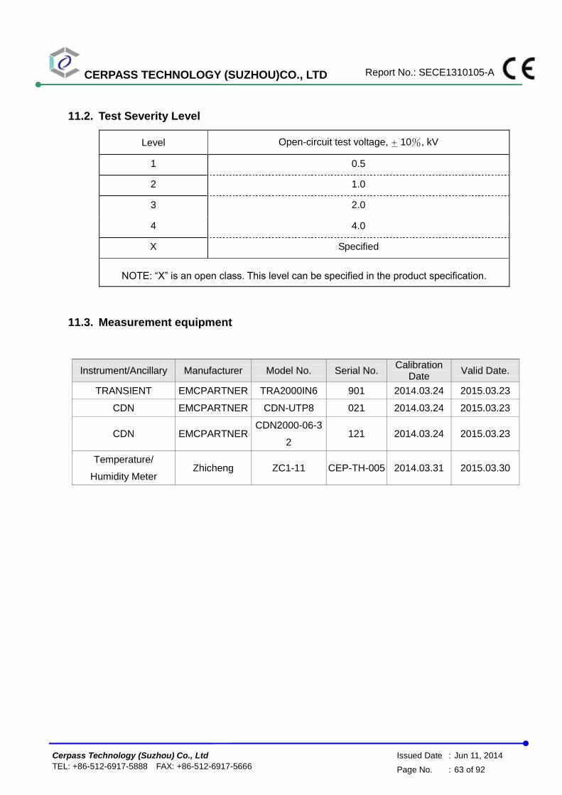
11.2. Test Severity Level
Level Open-circuit test voltage, ± 10%, kV
1 0.5
2 1.0
3 2.0
4 4.0
X Specified
NOTE: “X” is an open class. This level can be specified in the product specification.
11.3. Measurement equipment
Instrument/Ancillary Manufacturer Model No. Serial No. Calibration
Date Valid Date.
TRANSIENT EMCPARTNER TRA2000IN6 901 2014.03.24 2015.03.23
CDN EMCPARTNER CDN-UTP8 021 2014.03.24 2015.03.23
CDN EMCPARTNER CDN2000-06-3
2 121 2014.03.24 2015.03.23
Temperature/
Humidity Meter Zhicheng ZC1-11 CEP-TH-005 2014.03.31 2015.03.30
CERPASS TECHNOLOGY (SUZHOU)CO., LTD Report No.: SECE1310105-A
Cerpass Technology (Suzhou) Co., Ltd Issued Date : Jun 11, 2014
TEL: +86-512-6917-5888 FAX: +86-512-6917-5666 Page No. : 64 of 92
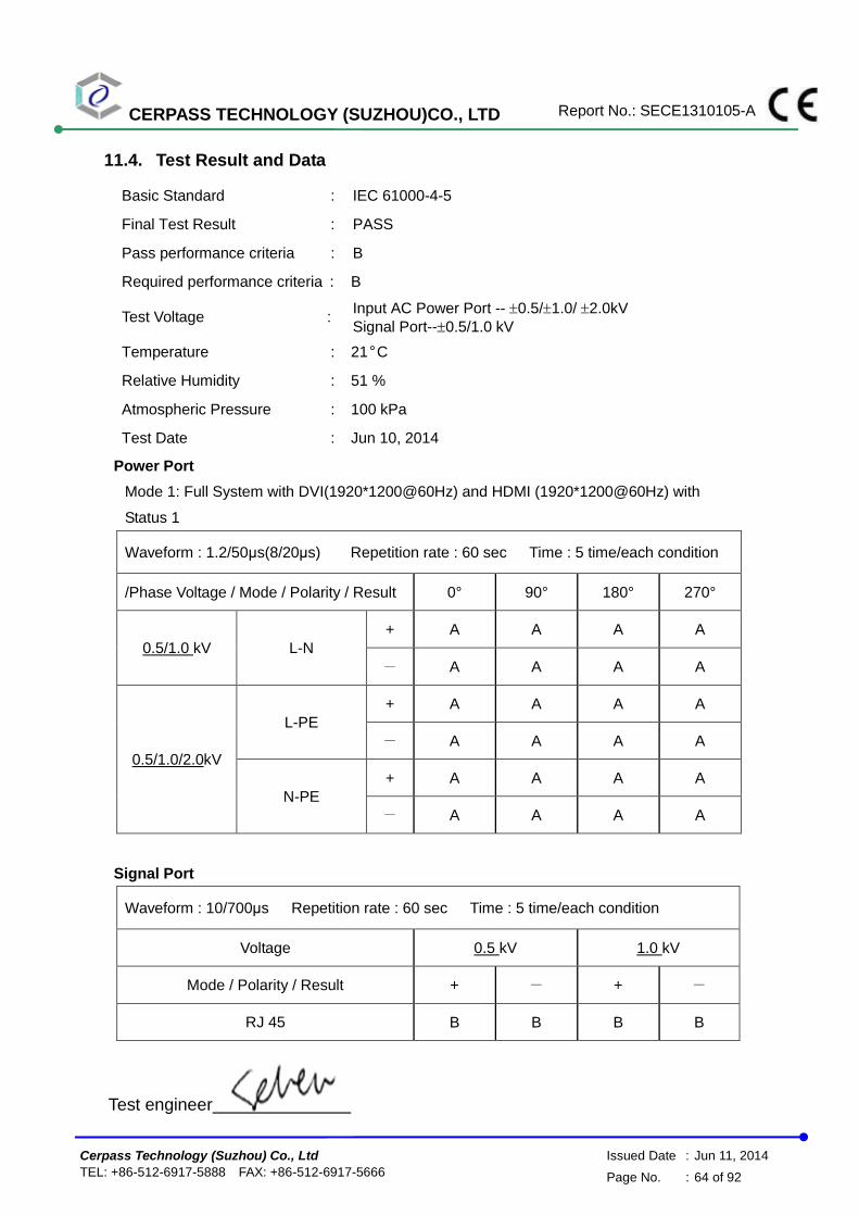
11.4. Test Result and Data
Basic Standard : IEC 61000-4-5
Final Test Result : PASS
Pass performance criteria : B
Required performance criteria : B
Test Voltage : Input AC Power Port -- 0.5/1.0/ 2.0kV
Signal Port--0.5/1.0 kV
Temperature : 21°C
Relative Humidity : 51 %
Atmospheric Pressure : 100 kPa
Test Date : Jun 10, 2014
Power Port
Mode 1: Full System with DVI(1920*1200@60Hz) and HDMI (1920*1200@60Hz) with
Status 1
Waveform : 1.2/50μs(8/20μs) Repetition rate : 60 sec Time : 5 time/each condition
/Phase Voltage / Mode / Polarity / Result 0° 90° 180° 270°
0.5/1.0 kV L-N
+ A A A A
- A A A A
0.5/1.0/2.0kV
L-PE
+ A A A A
- A A A A
N-PE
+ A A A A
- A A A A
Signal Port
Waveform : 10/700μs Repetition rate : 60 sec Time : 5 time/each condition
Voltage 0.5 kV 1.0 kV
Mode / Polarity / Result + - + -
RJ 45 B B B B
Test engineer
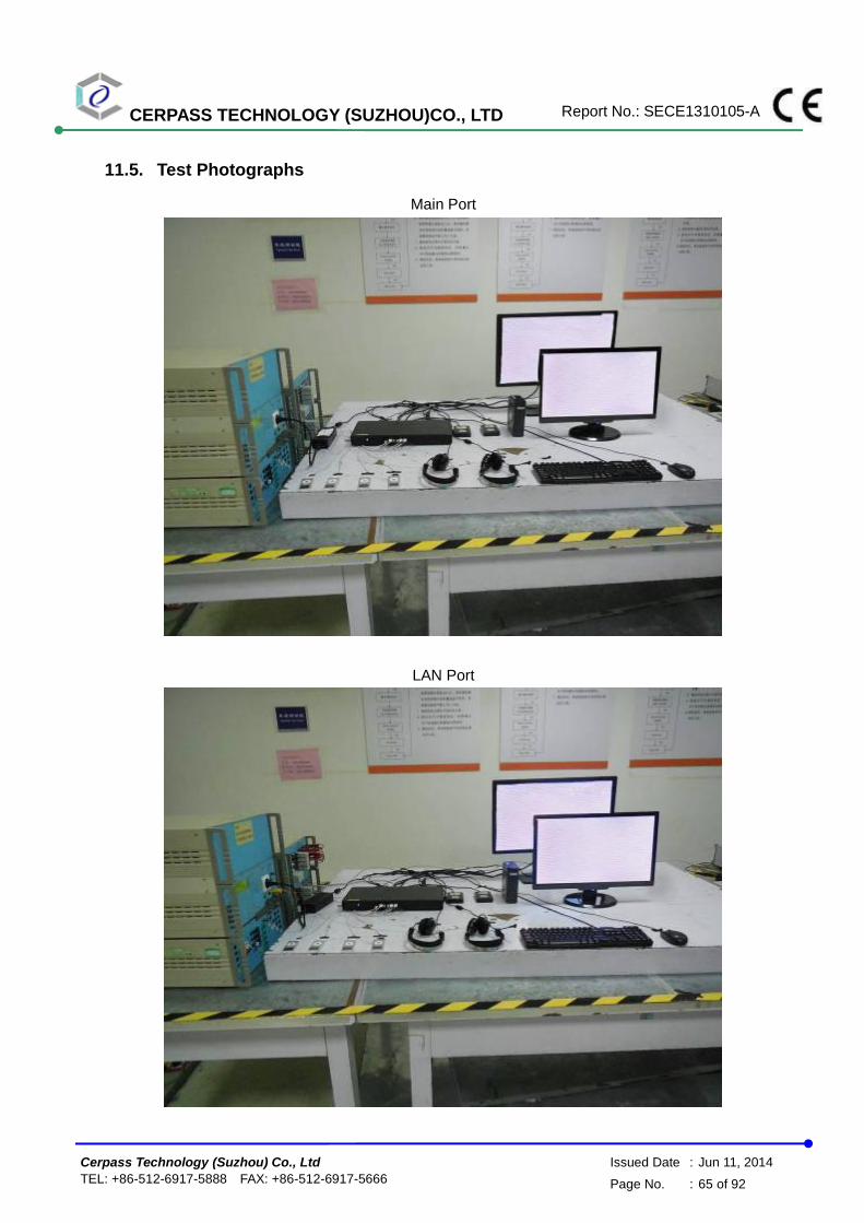
CERPASS TECHNOLOGY (SUZHOU)CO., LTD Report No.: SECE1310105-A
Cerpass Technology (Suzhou) Co., Ltd Issued Date : Jun 11, 2014
TEL: +86-512-6917-5888 FAX: +86-512-6917-5666 Page No. : 65 of 92
11.5. Test Photographs
Main Port
LAN Port

CERPASS TECHNOLOGY (SUZHOU)CO., LTD Report No.: SECE1310105-A
Cerpass Technology (Suzhou) Co., Ltd Issued Date : Jun 11, 2014
TEL: +86-512-6917-5888 FAX: +86-512-6917-5666 Page No. : 66 of 92
12. Conduction Disturbances induced by Radio-Frequency Fields
12.1. Test Procedure
a. The EUT shall be operated within its intended climatic conditions. The temperature
and relative humidity should be recorded.
b. This test method test can be performed without using a sell shielded enclosure. This
is because the disturbance levels applied and the geometry of the setups are not likely
to radiated a high amount of energy, especially at the lower frequencies. If under
certain circumstances the radiated energy is too high, a shielded enclosure has to be
used.
c. The test shall be performed with the test generator connected to each of the coupling
and decoupling devices in turn while the other non-excited RF-input ports of the
coupling devices are terminated by a 50 ohm load resistor.
d. The frequency range is swept from 150 KHz to 80 MHz, using the signal levels
established during the setting process, and with the disturbance signal 80% amplitude
modulated with a 1KHz sign wave, pausing to adjust the RF-signal level or to switch
coupling devices as necessary. The rate of sweep shall no exceed 1.5 x 10⁻³
decades/s. Where the frequency is swept incrementally, the step size shall no exceed
1% of the start and thereafter 1% of the preceding frequency value.
e. The dwell time at each frequency shall not be less than the time necessary for the EUT
to be exercised, and able to respond. Sensitive frequencies e.g. clock frequency (ies)
and harmonics or frequencies of dominant interest shall be analyzed separately.
f. An alternative test procedure may be adopted, wherein the frequency range is swept
incrementally, with a step size not exceeding 4% of the start ad thereafter 4% of the
preceding frequency value. The test level should be at least twice the value of the
specified test level.
g. In cases of dispute, the test procedure using a step size not exceeding 1% of the start
and thereafter 1% of preceding frequency value shall take precedence.
h. Attempts should be made to fully exercise the EUT during testing, and to fully
interrogate all exercise modes selected for susceptibility.
i. The use of special exercising programs is recommended.
j. Testing shall be performed according to a Test Plan, which shall be included in the test
report.
k. It may be necessary to carry out some investigatory testing in order to establish some
aspects of the test plan.

CERPASS TECHNOLOGY (SUZHOU)CO., LTD Report No.: SECE1310105-A
Cerpass Technology (Suzhou) Co., Ltd Issued Date : Jun 11, 2014
TEL: +86-512-6917-5888 FAX: +86-512-6917-5666 Page No. : 67 of 92
12.2. Test Severity Levels
Level Voltage Level (e.m.f.)
1 1 V
2 3 V
3 10 V
x Specified
NOTE - x is an open class. This level can be specified in the product specification.
12.3. Measurement equipment
Instrument/Ancillary Manufacturer Model No. Serial No. Calibration
Date Valid Date.
Conducted immunity
test system FRANKONIA CIT-10/75 102D1294 2014.03.24 2015.03.23
EM Injection clamp FCC F-203I-23MM 536 2014.03.24 2015.03.23
CDN FRANKONIA CDN-T2 A3010029 2014.03.24 2015.03.23
CDN FRANKONIA CDN-T4 A3015017 2014.03.24 2015.03.23
CDN FRANKONIA CDN-T8 A3022010 2014.03.24 2015.03.23
CDN FRANKONIA CDN-M2 A3002037 2014.03.24 2015.03.23
CDN FRANKONIA CDN-M2+M3 A3011102 2014.03.24 2015.03.23
CDN FCC CDN-M5/32 A3013024 2014.03.24 2015.03.23
6 dB Attenuator FRANKONIA N/A N/A 2014.03.24 2015.03.23
Temperature/
Humidity Meter Zhicheng ZC1-11 CEP-TH-005 2014.03.31 2015.03.30

CERPASS TECHNOLOGY (SUZHOU)CO., LTD Report No.: SECE1310105-A
Cerpass Technology (Suzhou) Co., Ltd Issued Date : Jun 11, 2014
TEL: +86-512-6917-5888 FAX: +86-512-6917-5666 Page No. : 68 of 92
12.4. Test Result and Data
Basic Standard : IEC 61000-4-6
Final Test Result : PASS
Pass performance criteria : A
Required performance criteria : A
Coupling mode : CDN-(M2+M3) for AC power ports CDN-T4 for signal ports
Temperature : 21°C
Relative Humidity : 51%
Atmospheric Pressure : 100 kPa
Test Date : Jun 10, 2014
Mode 1: Full System with DVI(1920*1080@60Hz) and HDMI (1920*1080@60Hz)
Frequency : 0.15~80MHz, Modulation : AM 80%,1KHz sine wave, Dwell time: 3.0s
Frequency Step Size : 1 % of preceding frequency value
Frequency Test mode Voltage(V) Result
0.15 ~ 80MHz Power(M3) 3 A
0.15 ~ 80MHz RJ45 3 A
Test engineer:
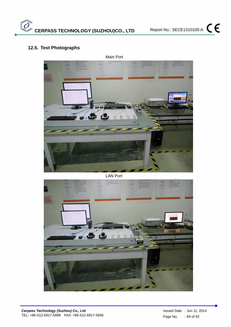
CERPASS TECHNOLOGY (SUZHOU)CO., LTD Report No.: SECE1310105-A
Cerpass Technology (Suzhou) Co., Ltd Issued Date : Jun 11, 2014
TEL: +86-512-6917-5888 FAX: +86-512-6917-5666 Page No. : 69 of 92
12.5. Test Photographs
Main Port
LAN Port
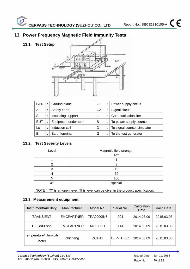
CERPASS TECHNOLOGY (SUZHOU)CO., LTD Report No.: SECE1310105-A
Cerpass Technology (Suzhou) Co., Ltd Issued Date : Jun 11, 2014
TEL: +86-512-6917-5888 FAX: +86-512-6917-5666 Page No. : 70 of 92
13. Power Frequency Magnetic Field Immunity Tests
13.1. Test Setup
GPR : Ground plane C1 : Power supply circuit
A : Safety earth C2 : Signal circuit
S : Insulating support L : Communication line
EUT : Equipment under test B : To power supply source
Lc : Induction coil D : To signal source, simulator
E : Earth terminal G : To the test generator
13.2. Test Severity Levels
Level Magnetic field strength
A/m
1 1
2 3
3 10
4 30
5 100
X1)
special
NOTE 1 “X” is an open level. This level can be givenin the product specification.
13.3. Measurement equipment
Instrument/Ancillary Manufacturer Model No. Serial No. Calibration
Date Valid Date.
TRANSIENT EMCPARTNER TRA2000IN6 901 2014.03.09 2015.03.08
H-Filed-Loop EMCPARTNER MF1000-1 144 2014.03.09 2015.03.08
Temperature/ Humidity
Meter Zhicheng ZC1-11 CEP-TH-005 2014.03.09 2015.03.08

CERPASS TECHNOLOGY (SUZHOU)CO., LTD Report No.: SECE1310105-A
Cerpass Technology (Suzhou) Co., Ltd Issued Date : Jun 11, 2014
TEL: +86-512-6917-5888 FAX: +86-512-6917-5666 Page No. : 71 of 92
13.4. Test Result and Data
Basic Standard : IEC 61000-4-8
Final Test Result : PASS
Pass performance criteria : A
Required performance criteria : A
Temperature : 21°C
Relative Humidity : 51 %
Atmospheric Pressure : 100 kPa
Test Date : Jun 11, 2014
Mode 1: Full System with DVI(1920*1200@60Hz) and HDMI (1920*1200@60Hz) with
Status 1
Power Frequency Magnetic Field : 50 Hz, 1 A/m
Coil Orientation Testing duration Results
X-axis 1.0 Min A
Y-axis 1.0 Min A
Z-axis 1.0 Min A
Test engineer:

CERPASS TECHNOLOGY (SUZHOU)CO., LTD Report No.: SECE1310105-A
Cerpass Technology (Suzhou) Co., Ltd Issued Date : Jun 11, 2014
TEL: +86-512-6917-5888 FAX: +86-512-6917-5666 Page No. : 72 of 92
13.5. Test Photographs

CERPASS TECHNOLOGY (SUZHOU)CO., LTD Report No.: SECE1310105-A
Cerpass Technology (Suzhou) Co., Ltd Issued Date : Jun 11, 2014
TEL: +86-512-6917-5888 FAX: +86-512-6917-5666 Page No. : 73 of 92
14. Voltage Dips and Voltage Interruptions Immunity Test Setup
14.1. Test Conditions
1. Source voltage and frequency : 230V / 50Hz, Single phase.
2. Test of interval : 10 sec.
3. Level and duration : Sequence of 3 dips/interrupts.
4. Voltage rise (and fall) time : 1 5 s.
5. Test severity :
Voltage dips and Interrupt reduction (%) Test Duration
(period)
>95% 250
30% 25
>95% 0.5
14.2. Measurement equipment
Instrument/Ancillary Manufacturer Model No. Serial No. Calibration
Date Valid Date.
TRANSIENT EMCPARTNER TRA2000IN6 901 2014.03.24 2015.03.23
Temperature/ Humidity
Meter Zhicheng ZC1-11 CEP-TH-005 2014.03.31 2015.03.30

CERPASS TECHNOLOGY (SUZHOU)CO., LTD Report No.: SECE1310105-A
Cerpass Technology (Suzhou) Co., Ltd Issued Date : Jun 11, 2014
TEL: +86-512-6917-5888 FAX: +86-512-6917-5666 Page No. : 74 of 92
14.3. Test Result and Data
Basic Standard : IEC 61000-4-11
Final Test Result : PASS
Pass performance Criteria : C for voltage interruption, B for voltage dips
Required performance Criteria : C for voltage interruption, B/C for voltage dips
Temperature : 21°C
Relative Humidity : 51%
Atmospheric Pressure : 100 kPa
Test Date : Jun 11, 2014
Mode 1: Full System with DVI(1920*1200@60Hz) and HDMI (1920*1200@60Hz) with Status 1
Voltage(UT): AC 230-240V 50 Hz Interval(s) : 10s Times : 3
Test mod
Test level reduction
%
Durations (period /
ms )
Phase / Result
0 45 90 135 180 225 270 315
Voltage
interruptions >95% 250 C C C C C C C C
Voltage dips
30% 25 A A A A A A A A
>95% 0.5 A A A A A A A A
Test engineer:

CERPASS TECHNOLOGY (SUZHOU)CO., LTD Report No.: SECE1310105-A
Cerpass Technology (Suzhou) Co., Ltd Issued Date : Jun 11, 2014
TEL: +86-512-6917-5888 FAX: +86-512-6917-5666 Page No. : 75 of 92
14.4. Test Photographs

CERPASS TECHNOLOGY (SUZHOU)CO., LTD Report No.: SECE1310105-A
Cerpass Technology (Suzhou) Co., Ltd Issued Date : Jun 11, 2014
TEL: +86-512-6917-5888 FAX: +86-512-6917-5666 Page No. : 76 of 92
15. Photographs of EUT
1) EUT Photo
2) EUT Photo

CERPASS TECHNOLOGY (SUZHOU)CO., LTD Report No.: SECE1310105-A
Cerpass Technology (Suzhou) Co., Ltd Issued Date : Jun 11, 2014
TEL: +86-512-6917-5888 FAX: +86-512-6917-5666 Page No. : 77 of 92
3) EUT Photo
4) EUT Photo

CERPASS TECHNOLOGY (SUZHOU)CO., LTD Report No.: SECE1310105-A
Cerpass Technology (Suzhou) Co., Ltd Issued Date : Jun 11, 2014
TEL: +86-512-6917-5888 FAX: +86-512-6917-5666 Page No. : 78 of 92
5) EUT Photo
6) EUT Photo

CERPASS TECHNOLOGY (SUZHOU)CO., LTD Report No.: SECE1310105-A
Cerpass Technology (Suzhou) Co., Ltd Issued Date : Jun 11, 2014
TEL: +86-512-6917-5888 FAX: +86-512-6917-5666 Page No. : 79 of 92
7) EUT Photo
8) EUT Photo

CERPASS TECHNOLOGY (SUZHOU)CO., LTD Report No.: SECE1310105-A
Cerpass Technology (Suzhou) Co., Ltd Issued Date : Jun 11, 2014
TEL: +86-512-6917-5888 FAX: +86-512-6917-5666 Page No. : 80 of 92
9) EUT Photo
10) EUT Photo
v
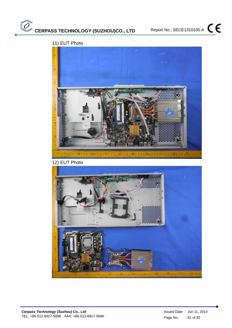
CERPASS TECHNOLOGY (SUZHOU)CO., LTD Report No.: SECE1310105-A
Cerpass Technology (Suzhou) Co., Ltd Issued Date : Jun 11, 2014
TEL: +86-512-6917-5888 FAX: +86-512-6917-5666 Page No. : 81 of 92
11) EUT Photo
12) EUT Photo

CERPASS TECHNOLOGY (SUZHOU)CO., LTD Report No.: SECE1310105-A
Cerpass Technology (Suzhou) Co., Ltd Issued Date : Jun 11, 2014
TEL: +86-512-6917-5888 FAX: +86-512-6917-5666 Page No. : 82 of 92
13) EUT Photo
14) EUT Photo

CERPASS TECHNOLOGY (SUZHOU)CO., LTD Report No.: SECE1310105-A
Cerpass Technology (Suzhou) Co., Ltd Issued Date : Jun 11, 2014
TEL: +86-512-6917-5888 FAX: +86-512-6917-5666 Page No. : 83 of 92
15) EUT Photo
16) EUT Photo
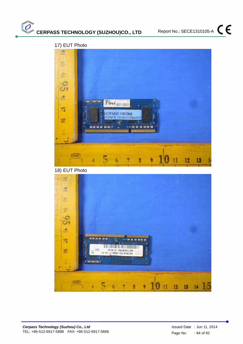
CERPASS TECHNOLOGY (SUZHOU)CO., LTD Report No.: SECE1310105-A
Cerpass Technology (Suzhou) Co., Ltd Issued Date : Jun 11, 2014
TEL: +86-512-6917-5888 FAX: +86-512-6917-5666 Page No. : 84 of 92
17) EUT Photo
18) EUT Photo

CERPASS TECHNOLOGY (SUZHOU)CO., LTD Report No.: SECE1310105-A
Cerpass Technology (Suzhou) Co., Ltd Issued Date : Jun 11, 2014
TEL: +86-512-6917-5888 FAX: +86-512-6917-5666 Page No. : 85 of 92
19) EUT Photo
20) EUT Photo
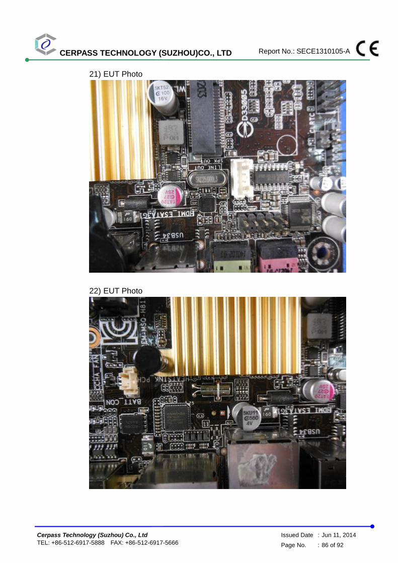
CERPASS TECHNOLOGY (SUZHOU)CO., LTD Report No.: SECE1310105-A
Cerpass Technology (Suzhou) Co., Ltd Issued Date : Jun 11, 2014
TEL: +86-512-6917-5888 FAX: +86-512-6917-5666 Page No. : 86 of 92
21) EUT Photo
22) EUT Photo

CERPASS TECHNOLOGY (SUZHOU)CO., LTD Report No.: SECE1310105-A
Cerpass Technology (Suzhou) Co., Ltd Issued Date : Jun 11, 2014
TEL: +86-512-6917-5888 FAX: +86-512-6917-5666 Page No. : 87 of 92
23) EUT Photo
24) EUT Photo

CERPASS TECHNOLOGY (SUZHOU)CO., LTD Report No.: SECE1310105-A
Cerpass Technology (Suzhou) Co., Ltd Issued Date : Jun 11, 2014
TEL: +86-512-6917-5888 FAX: +86-512-6917-5666 Page No. : 88 of 92
25) EUT Photo
26) EUT Photo
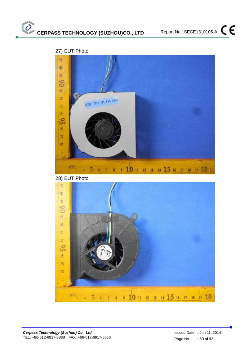
CERPASS TECHNOLOGY (SUZHOU)CO., LTD Report No.: SECE1310105-A
Cerpass Technology (Suzhou) Co., Ltd Issued Date : Jun 11, 2014
TEL: +86-512-6917-5888 FAX: +86-512-6917-5666 Page No. : 89 of 92
27) EUT Photo
28) EUT Photo
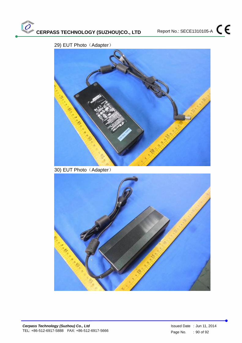
CERPASS TECHNOLOGY (SUZHOU)CO., LTD Report No.: SECE1310105-A
Cerpass Technology (Suzhou) Co., Ltd Issued Date : Jun 11, 2014
TEL: +86-512-6917-5888 FAX: +86-512-6917-5666 Page No. : 90 of 92
29) EUT Photo(Adapter)
30) EUT Photo(Adapter)

CERPASS TECHNOLOGY (SUZHOU)CO., LTD Report No.: SECE1310105-A
Cerpass Technology (Suzhou) Co., Ltd Issued Date : Jun 11, 2014
TEL: +86-512-6917-5888 FAX: +86-512-6917-5666 Page No. : 91 of 92
31) EUT Photo(Adapter)
32) EUT Photo(Adapter)
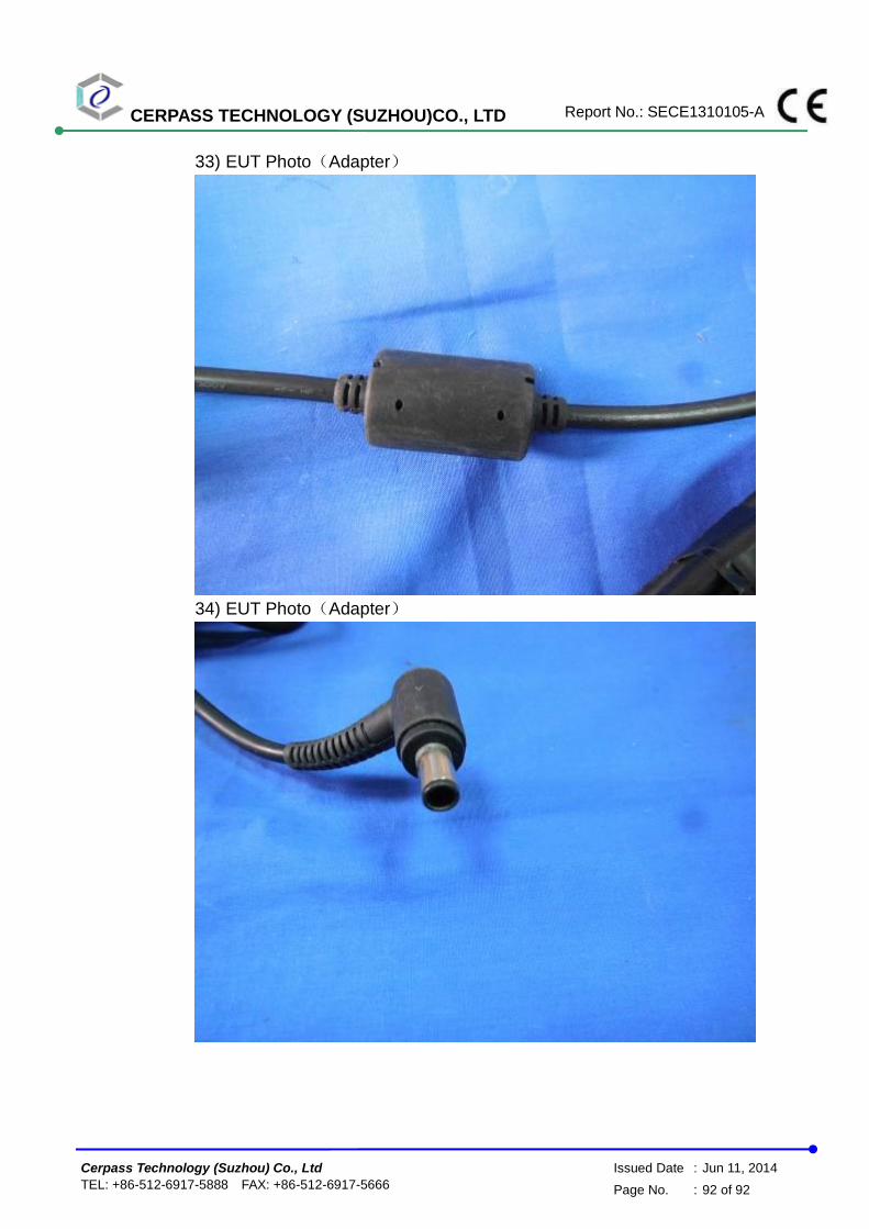
CERPASS TECHNOLOGY (SUZHOU)CO., LTD Report No.: SECE1310105-A
Cerpass Technology (Suzhou) Co., Ltd Issued Date : Jun 11, 2014
TEL: +86-512-6917-5888 FAX: +86-512-6917-5666 Page No. : 92 of 92
33) EUT Photo(Adapter)
34) EUT Photo(Adapter)