embedded hardware and software self-testing methodologies for processor cores li chen, sujit dey,...
Post on 20-Dec-2015
227 views
TRANSCRIPT

Embedded Hardware and Software Self-Testing Methodologies for Processor Cores
Li Chen, Sujit Dey, Pablo Sanchez, Krishna Sekar, and Ying Chen
Design Automation Conference, 2000
Page(s): 625~630
Presented by
Kao, Chung-Fu
10/23/2000 2
What’s the Problems ?
Current external testers vs. GHz processors.
– Test speed, equipment cost ($20 million)
Does hardware BIST good enough ?
Why not Software-Based Self-Testing.
– Low cost, high-quality self-test methodology
10/23/2000 3
Outline
Introduction
Two case: PARWAN and PicoJava-II processor cores
– Proof that hardware BIST still has many limitations
Demonstrate that software-based self-testing methodology is a better approach
Experiment and conclusion
10/23/2000 4
Introduction
Generate the required test patterns on-chip
– At-speed testing, reduce the cost
Built-In Self-Test (BIST)
– Use for memory logic due to regular structure
How to test non-memory parts ?
Software-based self-testing
10/23/2000 5
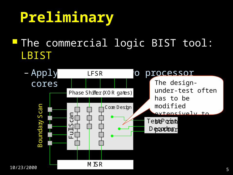
Preliminary
The commercial logic BIST tool: LBIST
– Applying BIST to two processor cores
Bo
un
da
ry S
can
LFSR
Phase Shifter (XOR gates)
Core Design
MISR
Test PointDecoder
Fu
ll S
can
The design-under-test often has to be modified extensively to be random pattern testable

10/23/2000 6
Case Study I: PARWAN
We should modify the design in order to make the application of LBIST effective.
1. Splitting all bi-directional pins into separate I/O pins
2. Replacing all tri-state buffers with selectors
3. Inserting test points to improve the testability of the circuit
10/23/2000 7
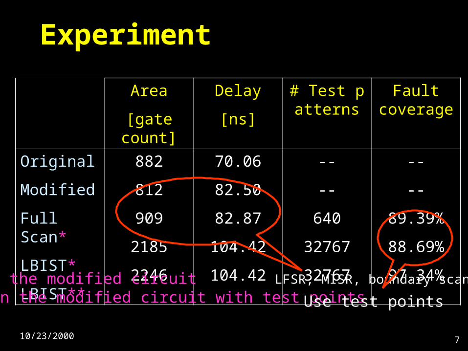
Experiment
Area
[gate count]
Delay
[ns]
# Test patterns
Fault coverage
Original
Modified
Full Scan*
LBIST*
LBIST**
882
812
909
2185
2246
70.06
82.50
82.87
104.42
104.42
--
--
640
32767
32767
--
--
89.39%
88.69%
97.34%* On the modified circuit** On the modified circuit with test points
LFSR, MISR, boundary scan
Use test points
10/23/2000 8
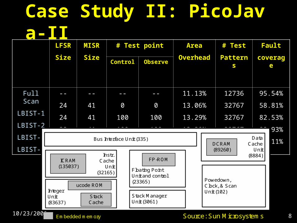
Case Study II: PicoJava-II LFSR
Size
MISR
Size
# Test point Area
Overhead
# Test
Patterns
Fault
coverageControl Observe
Full Scan
LBIST-1
LBIST-2
LBIST-3
LBIST-4
--
24
24
32
24
--
41
41
41
41
--
0
100
100
100
--
0
100
100
100
11.13%
13.06%
13.29%
13.30%
13.30%
12736
32767
32767
32767
1,000,000
95.54%
58.81%
82.53%
82.93%
84.11%
Bus Interface Unit (335)
Powedown,Clock, & ScanUnit (102)
Stack ManagerUnit (3061)
Instr.Cache
Unit(32165)
ICRAM(135037)
IntegerUnit(83637)
ucode ROM
StackCache
Floating PointUnit and control(23365)
FP-ROM
DataCache
Unit(8884)
DCRAM(89260)
Embedded memory Source: Sun Microsystems
10/23/2000 9
Software-Based Self-Testing
Uses a software tester embedded in the processor memory
For test generation and test application
Advantages
– Programmability;
– Flexibility;
– Generates desirable random test sets on-chip
– No need of scan chains and boundary scan

10/23/2000 10
The Software-Based Self-Testing Methodology
The self-testing scheme includes two steps
– Test preparation step
– Self-testing step
Self-testsignature
TestPattern
Responsesignature
TestResponse
Test responseanalysisprogram
TestApplication
program
On-chip testgenerationprogram
D-C
ac
he
I-C
ac
he
So
ftw
are
Te
ste
r
Program Execution
10/23/2000 11
Step 1: Component Test Preparation
The test need of the component by aself-test signature
– The seed (S)
– The configuration (C)
– The number of test patterns to be generated (N)
Instruction-based testing
10/23/2000 12
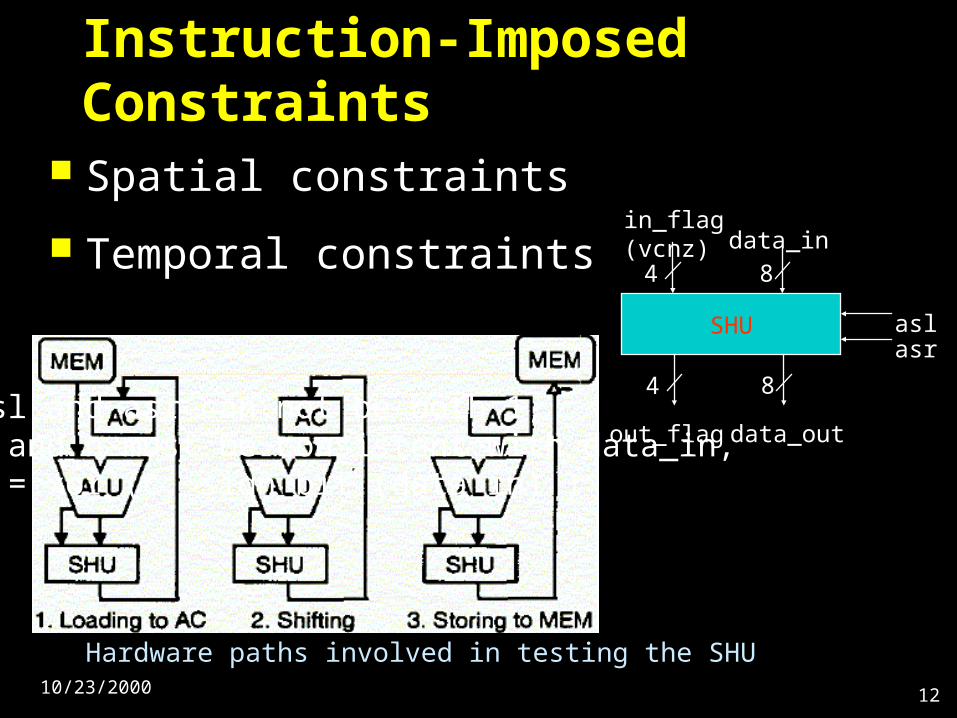
Instruction-Imposed Constraints
Spatial constraints
Temporal constraints
SHU
4 8
4 8
in_flag(vcnz) data_in
out_flag data_out
aslasr
Hardware paths involved in testing the SHU
Ex:1. asl and asr can not be both 1,2. z and n must be consistent with data_in,3. v = xor (c, sign_bit (data_in) )

10/23/2000 13
Constraint Modeling
Spatial constrain
– Random patterns used on independent inputs
Temporal constrain
– As figure shown
10/23/2000 14
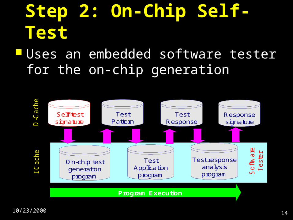
Step 2: On-Chip Self-Test
Uses an embedded software tester for the on-chip generation
Self-testsignature
TestPattern
Responsesignature
TestResponse
Test responseanalysisprogram
TestApplication
program
On-chip testgenerationprogram
D-C
ach
eI-
Ca
ch
e
So
ftw
are
Te
ste
r
Program Execution
10/23/2000 15
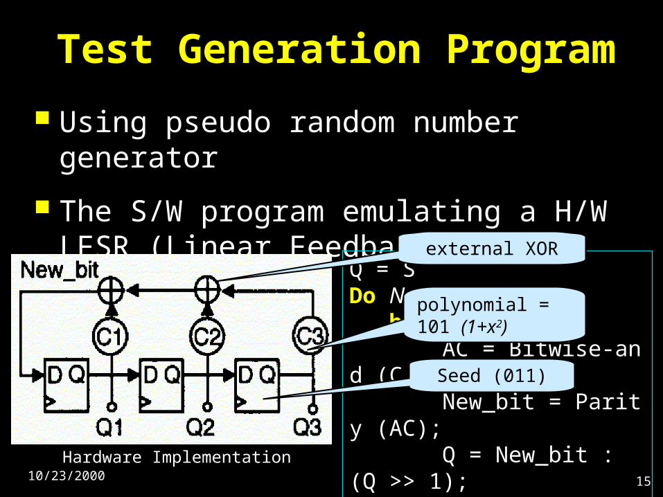
Test Generation Program
Using pseudo random number generator
The S/W program emulating a H/W LFSR (Linear Feedback Shift Register)
Q = SDo N times begin AC = Bitwise-and (C, Q); New_bit = Parity (AC); Q = New_bit : (Q >> 1); end
external XOR gate
polynomial = 101 (1+x2)
Seed (011)
Hardware Implementation
10/23/2000 16
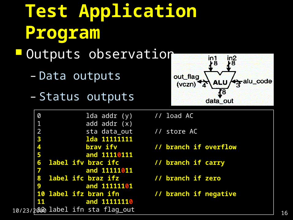
Test Application Program
Outputs observation
– Data outputs
– Status outputs
0 lda addr (y) // load AC1 add addr (x)2 sta data_out // store AC3 lda 111111114 brav ifv // branch if overflow5 and 111101116 label ifv brac ifc // branch if carry7 and 111110118 label ifc braz ifz // branch if zero9 and 1111110110 label ifz bran ifn // branch if negative11 and 1111111012 label ifn sta flag_out
10/23/2000 17
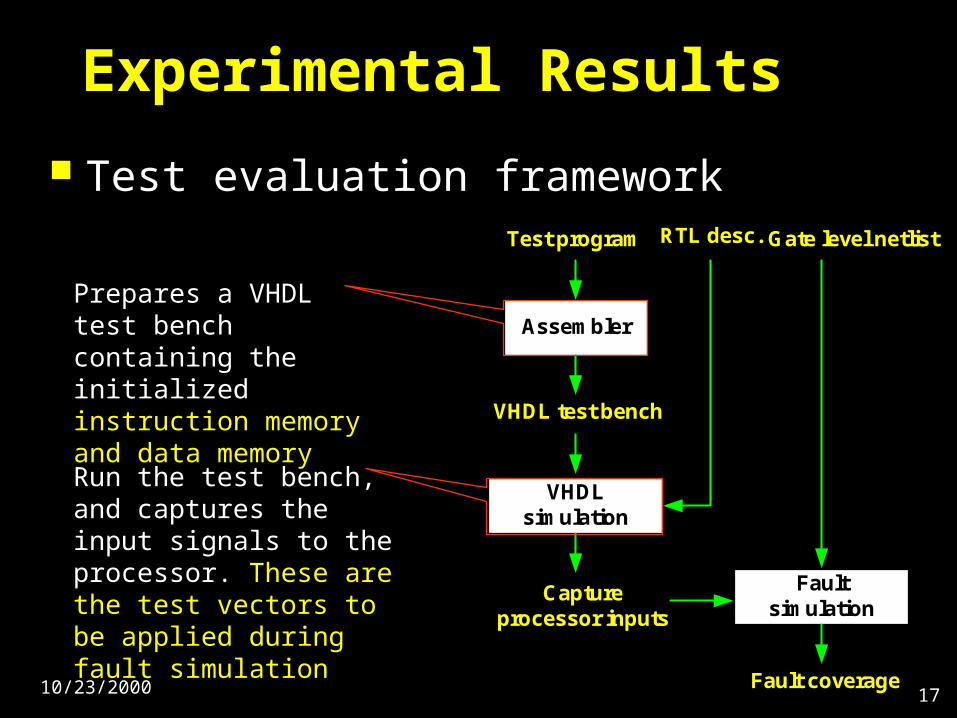
Experimental Results
Test evaluation framework
Assembler
VHDLsimulation
Faultsimulation
Test program
VHDL test bench
Captureprocessor inputs
Gate level netlist
Fault coverage
RTL desc.
Prepares a VHDL test bench containing the initialized instruction memory and data memory
Run the test bench, and captures the input signals to the processor. These are the test vectors to be applied during fault simulation
10/23/2000 18
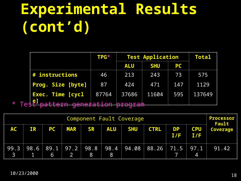
Experimental Results (cont’d)
TPG* Test Application Total
ALU SHU PC
# instructions
Prog. Size [byte]
Exec. Time [cycle]
46
87
87764
213
424
37686
243
471
11604
73
147
595
575
1129
137649
Component Fault Coverage Processor Fault
CoverageAC IR PC MAR SR ALU SHU CTRL DP I/F CPU I/F
99.33 98.61 89.16 97.22 98.88 98.48 94.08 88.26 71.57 97.14 91.42
* Test pattern generation program
10/23/2000 19
Conclusion
Demonstrated some of the disadvantages associated with H/W-based BIST tech.
We hope that no need to change design when insert the test mechanism.
Software-based self-testing tech. had proposed
– No hardware overhead
– Save money