email - subject: refute 3.1 for review
TRANSCRIPT

Lake, Louis 0 ".
From:Sent:To:Subject:Attachments:
Lake, LouisTuesday, November 24, 2009 9:25 AMCarrion, RobertFW: Refute 3.1 for Review El ,'A
-- FM 3.1.ppt; Exhibit 4 - Graph of air from tickets.pdf; Exhibit 1 - Erhn Hime Petro report, .- , ,05101976.pdf; Exhibit 2 - Core Bore #5 Final CTL Petrographic Report 059169 C856.pdf;Exhibit 3 - pour ticket samples - Pour666RBElevl6O.pdf
S/,
From: Williams, Charles R. [mailto:[email protected]]Sent: Tuesday, November 24, 2009 7:12 AMTo: Lake, Louis; Thomas, George; [email protected]: Herrin, Dennis W.Subject: Refute 3.1 for Review
Mr Lake,I am resending due to difficulty with opening/reading the previous attachments. Again, this is prelim. Call me withquestions. It looks'like I will need to send each one as separate emails to keep from mixing documents.
Thank you,Charles Williams919-516-7417
K'

3.1 Inadequate Air ContentMay identify additional perspective on this
issue as RCA related efforts proceeds
Description: Excessive amount of uncontrolled air contained within the concrete as a result of mixing/placingoperations could cause voids. These voids of variable size and shape create weakness in the matrix.Excessive volume of air voids (entrained and entrapped) can weaken the concrete, provide an initiationzone for cracks, and increases potential for shrinkage/creep.
Data to be Collected and Analyzed:(1) Petrographic analysis (Exhibits 1 & 2)(2) Review pour tickets for measured air during construction (Exhibit 3). Exhibit 4 is a graph of the data
from those pours.
Verified Refuting Evidence:1. Amount of entrained air is within acceptable
range according to Petrographic analysis.2. Pour ticket review shows the air entrained
admixture (DAREX) was used in all concretepours in accordance with the designspecifications.
3. Analysis of measured air confirmed that aircontent was within specifications.
Reviewed by: Dr. Avi Mor, 352-795-6486, ext 1030 -P11 CR3 Team Office
Verified Supporting Evidence:
a
11/23/2009 neot receaso to a third part, withm~t-11/232009• I

St T 5i7A/i0
ERLIN, HIME ASSOCIATES
MATERIAL. ANO CONCRETE CONSULTANTS
ISKCtKtE BOULEV'ARD
"LL." NOtS 60062
(312) 272.7730
" , .. :r : --:
PETROGRAPHIC' STUDIES O0F COG0NCRET'E
FOR
CONSTRUCTION ENGINEERING CONSULTANTS
* * * * *'* * *
SUMMU'ARY AND DISCUSSION..
-The specimen represented~ air-entrained concrete.made with, crushed fossiliferous coarse aggre-gate and'siliceous fine aggregate arnd a lowwater-cement ratio paste. There was no evidencethat the aggregates had been either chemically,or physically unsound.
'~The specimen was from a~n area, where fractures~had existed for a period of time and wheremoisture had been present. That was demon-kstrated by secondary deposits on fractur~esurfaces.
The specimen was relatively small. Largerspecimens fr.orn diffqrent areas of the struc-ture would be desirable for examination inorder to obtain abetter representation of. theconcrete....
INTRODUCTION
R eported herein are the results of petrographic studiesof a concrete fragment submitted by J. Artuso of' Con-struction Engineering Consultants. The specimen is fromthe dome of the containment structuire of' the FloridaPower Corporation, Crystal River, Unit III .
S .Requested by Mr. Artuso. were petrographic studies forevaluating the specimen, and particularly for evidenceof-f£eatures~ that' would cause 'volume instability.
C-12
9..
ERLIN. HIME ASSOCIATES 'MATERIALS ANO CONCRET, CONSULTANTS
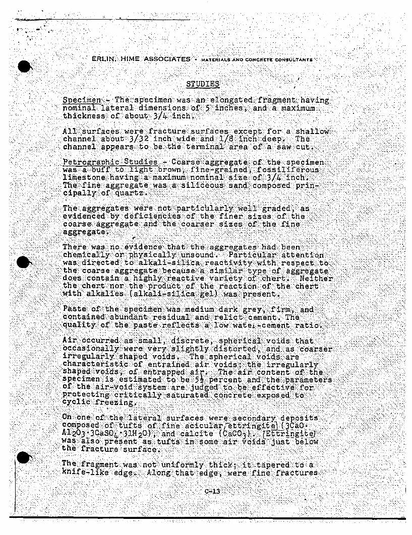
STUDIES-/
Specimen - The sp-ecimen was an elongated fragment havingnominal lateral dimensionsa. ''of 5 'inches, and a maximumthickness of about 3/4 in.ch.
All *surfaces were fracture' surfaces except for achannel about 3/32 inch wide and 1/8 tinch deep.channel appears to be the terminal area of' a saw
shallowThecut.
.PetrograDhic Studies - Coarse aggregate, of the specimen.:wasa buff t:o light brown, fine-grained, fossiliferouslimestone having a maximum nominal-size of 3/4 inch.The fine aggregate was a siliceous sand composed prin-.cipally of quartz.
The aggregates were not. pa~rticliiarly well graded, as.evidenced by deficiencies of the finer sizes of thecoarse aggregate and the coarser sizes of the fineaggregate.
*There was 'no Ovide~nce that 'the aggregates had beenS::chemically ,or physically unsound. ,Particular attention
was directed to alkali-silica reactivity with respect tothe ''oar-se aggregate because *a similar type ofI aggregate.does co ,ntain a highly reactive' variety of chert. Neitherthe chert nor the pr6duct of the reaction of the chert :with alkalies (alkali-silica gel) was present.
Paste of the specitfien was medium dark grey', firm,' andcontained abundant ~residual and relict c~ement. Thequality of the ~paste reflects a low watei-cement ratio.
Air occurred as small, discrete, spherical~ voids thatbccasionally were very slightly distorted, aind as coarserirregularly shaped voids. The spherical v'oids arecharacteristic of entrained air voids; the irregularlyshaped1 voids,: 'of' entrapped air., The" air .conten~t of' thespecimen is ""estimated to be 512 percent and the parametersof' the air-void system are judgred to be effective: forprotecting 'critically saturated concrete exposed" tocyclic f'reezing.
On one of the lateral surf'aces were secondary deposit'scomposed of 'tufts of fine acicularettri'ngit. ý (3aO.A1203.3CaSO4.31H 20), and calcite (6aCO 3). -Ett5Hngit ewas also present as tufts in some air voids'-just belo-wthe fracture-surface. ' -
V The fragment was not uniformly thick; it tapered to aknife-like edge. Along that edge, were fine fracture Is
* c-u

ERLINK, HIME. :ASSOCIATES. MATERIALS-ANO CONCR•TE CONSULTANTS
oriented subparallel to the long axis of the fragment.The fractures transected coarse aggregate particles. Onthose fracture s-urfaces were secondary deposits similarto those described above.
==The secondary compounds demonstrate that the fragmentwas from an area where fractures present for a periodof time had been exposed to moisture.
May 10, 1976 Erlin, i-rime Associates, Inc.
by Bernard Erlin, PresidentPetrographer
~EF
c-14
*0 n ninn
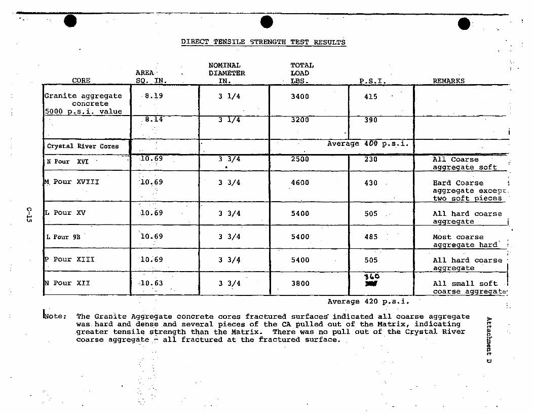
DIRECT TENSILE STRENGTH TEST RESULTS
AREA.-SQ. IN.
NOMINALDIAMETER
IN.
TOTALLOADLBS.CORE P.S.I REMARKS
Granite aggregate 8.19 3 1/4 3400 415concrete5000 p.s.i, value ________ ______ _________8.14 3 1/4 3200 390
Crystal River Cores Average 400 p.s.i.
N Pour XVI - 10.69 3 3/4 2500 230 All Coarse....... _ __ __._aggregate soft
M.Pour XVIII 10.69 3 3/4 4600 430 Hard Coarseaggregate exceDt.two soft pieces
L Pour XV 10.69 3 3/4 5400 505 All hard coarse______aggregate
L Pour 9B 10.69 3 3/4 5400 485 Most coarse._ _,._aggregate hard'
P Pour XIII 10.69 3 3/4 5400 505 All hard coarse -
____ _,,_ _ ,aggregate
Pour XII 10.63 3 3/4 3800 3 All small softcoarse aggregate'
Average 420 p.s.i.
I
6ote: The Granite Aggregate concrete cores fractured surfaces indicated all coarse aggregatewas hard and dense and several pieces of the CA pulled out of the Matrix, indicating.greater tensile strength than the Matrix. There was no pull out of the Crystal Rivercoarse aggregate - all fractured at the fractured surface.
rt
M

A &
ATTACHMENT E
pr eliminary Report ofCrystal River Coarse Aggregate
Sieve Wgt. Ret. % Passing
J.0 100
3/4 1.0 97
1/2 .15.8 58
3/8 28.4 24
4 35.8 4
8 ~ 36.3.3
Pan .37.3
Test Result
C-ll 200 Wash Loss 1.3% (Primarilydust of fr;
C-131 Los Angeles Abrasion 42 %
Cý-123 Lightweight Pieces in Aggregate 0.*2%
C-29 Unit Weight of Aggregate 85.68 lbs/cu. ft.
*C-142. Friable Particles .tater
C-235 .Soft Particles Later
C-88 'Soundness (Sodium -8ulphat~e) Later
C-127 Specific Gravity and Absorption Later
*This limit may be increased to 1.5% if the material finer thanessential of dust from fracture
ASTM Spec# 67
100
90-100
20-55
0-10
0-5
ASTM Specificati...
1% Max*acture)
50% Max
0.5% Max
No Spec
5.0% Max
5.0% Max
12.0% Max
No Spec
a No. 200 consists
Oz
C-16

• Copy No. I
Report forProgress, Energy
CTLGroup Project No. 059:169
Petrographic Examination of Concrete HalfCore from Delaminated Containment Wall,Crystal River, Florida
November 2, 2009
Submitted by:.Derek Brown
COA #4731
5400 Old Orchard RoadSkokie, Illinois 60077-1030(847) 965-7500
9030 Red Branch Road,. Suite 110Columbia, Maryland 21045
www.CTLGroup.com
GROUPK . a f wi1 e 'd q ý'ý. D~e II' a ri ResuP t a ;:.
CTLGroup is a registered dib/a of Construction Technology Laboratories, Inc.

qBuilding K edge, Delivering Resuls., www.CTLGroup.com
REPORT OF PETROGRAPHIC EXAMINATION
Date: November 2, 2009
CTLGroup Project No.: 059169
Petrographic Examination of Concrete Half Core from Delaminated Containment Wall,Crystal River, Florida
One saw cut half concrete core labeled Core #5 (Figs. 1 and 2) was received on October 27,2009 from Mr. Jerzy Zemajtis, Project Manager, CTLGroup on behalf of Mr. Paul Fagan of
Progress Energy, Crystal River, Florida. According to Mr. Zemajtis, the core represents the
outer portion of concrete from a containment wall and the core is fractured at its inner surface at
a delamination that was found to be present when access was gained to the wall interior. The
delamination is approximately at a depth of 200 mm (8.0 in.) where horizontal post tensioning
ducts are present.
Petrographic examination (ASTM C856-04) of the core was requested in order to determine, if
possible, if the delamination is a recent feature, or alternatively if it occurred at some earlier time
in the age of the structure.
FINDINGS AND CONCLUSIONS
The following findings result from the petrographic examination.
Based on the general appearance, and both the physical and microstructural properties, the
fracture at the point of delamination is most likely a fairly recent event. However, it is not
possible to be completely definitive about the time frame since an older fracture, if subsequently
well protected from air and moisture ingress, may also have similar characteristics.
The fracture surface passes through, not around the aggregates particles, is moderately hard,
and does not exhibit loose surface debris. There is an absence of significant microcracking inthe general vicinity of the fracture, and only limited evidence of surface deposits (slight
efflorescence).
Corporate Office: 5400 Old Orchard Road Skokie, Illinois 60077-1030 Phone: 847-965-7500 Fax: 847-965-6541
Washington D.C. Office: 9030 Red Branch Road, Suite 110 Columbia. Maryland 21045-2003 Phone: 410-997-0400 Fax: 410-997-8480
CTLGroup is a registered d/bla of Construction Technology Laboratories, Inc.

Progress Energy Page 2 of 10Crystal River November 2, 2009CTLGroup Project No. 059169
Carbonation to any significant depth from the fracture surface into the outer concrete is not
observed (Fig. 3). Incipient carbonation is exhibited in thin section at the immediate fracture
surface (Fig. 6a). However, an older delamination surface that was not exposed to air due to the
depth of outer concrete, and other possible wall coverings, may also have such an absence of
carbonation.
The cement hydration adjacent to the fracture is well advanced and comparable to that of the
body of the core (Figs. 6b and 6c). This suggests that there was no moisture ingress to the
fracture surface, over a period of time long enough, to change the general degree of hydration.
This is supported by an absence of secondary deposits within air voids adjacent to the fracture
surface.
Additional Comments
The concrete represented by Core #5 is well consolidated and free of any cracks or excessive
microcracks (Fig. 4). The concrete consists of crushed carbonate rock coarse aggregate and
natural sand fine aggregate, well distributed in a portland cement paste. No evidence is
exhibited of any deleterious chemical reactions involving the cement paste and / or aggregates.
The concrete could be considered marginally air entrained based on an approximate volume of
1 to 2% of small, spherical entrained air voids in the hardened cement paste (Fig. 5).
Based on the physical properties and microstructure of the hydrated cement paste, and the tight
aggregate to paste bond, lack of major cracks and microcracks, and absence of a materials-
related distress mechanism, the concrete is considered to be in good condition.
Further details of the petrographic examination are given in the following image and data
sheets.
METHODS OF TEST
Petrographic examination of the provided sample was performed in accordance with ASTM
C 856-04, "Standard Practice for Petrographic Examination of Hardened Concrete." The core
was visually inspected and photographed as received. The core half was ground (lapped) on the
saw cut surface to produce a smooth, flat, semi-polished surface. Lapped and freshly broken
surfaces of the concrete were examined using a stereomicroscope at magnifications up to 45X.
Ct ROUP.B0gnede Oft~fes*ft, ~wwwCL1U.~
Progress Energy Page 3 of 10Crystal River November 2, 2009CTLGroup Project No. 059169
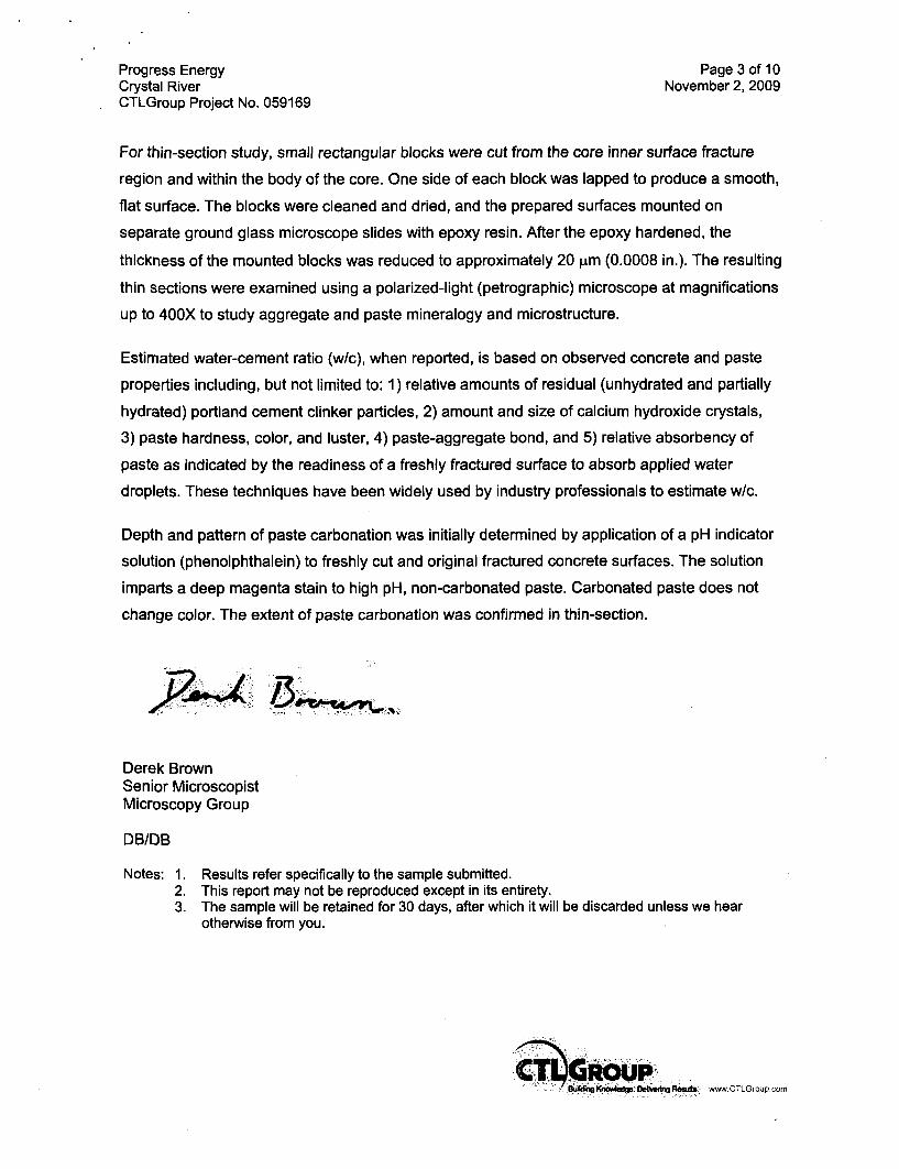
For thin-section study, small rectangular blocks were cut from the core inner surface fracture
region and within the body of the core. One side of each block was lapped to produce a smooth,
flat surface. The blocks were cleaned and dried, and the prepared surfaces mounted on
separate ground glass microscope slides with epoxy resin. After the epoxy hardened, the
thickness of the mounted blocks was reduced to approximately 20 gim (0.0008 in.). The resulting
thin sections were examined using a polarized-light (petrographic) microscope at magnifications
up to 400X to study aggregate and paste mineralogy and microstructure.
Estimated water-cement ratio (w/c), when reported, is based on observed concrete and paste
properties including, but not limited to: 1) relative amounts of residual (unhydrated and partially
hydrated) portland cement clinker particles, 2) amount and size of calcium hydroxide crystals,
3) paste hardness, color, and luster, 4) paste-aggregate bond, and 5) relative absorbency of
paste as indicated by the readiness of a freshly fractured surface to absorb applied water
droplets. These techniques have been widely used by industry professionals to estimate w/c.
Depth and pattern of paste carbonation was initially determined by application of a pH indicator
solution (phenolphthalein) to freshly cut and original fractured concrete surfaces. The solution
imparts a deep magenta stain to high pH, non-carbonated paste. Carbonated paste does not
change color. The extent of paste carbonation was confirmed in thin-section.
Derek BrownSenior MicroscopistMicroscopy Group
DB/DB
Notes: 1. Results refer specifically to the sample submitted.2. This report may not be reproduced except in its entirety.3. The sample will be retained for 30 days, after which it will be discarded unless we hear
otherwise from you.
" g!:'c''c ' Oe gRAi.s , wv,.CTL GOU p.co

Progress EnergyCrystal RiverCTLGroup Project No. 059169
Page 4 of 10November 2, 2009
Ia. Curved surface. Outer end Is to the left.
lb. Saw cut surface. Outer end Is to the left
Fig. I Side views of Core #5, as received for examination.
www.CTLGmup~com

Progress EnergyCrystal RiverCTLGroup Project No. 059169
Page 5 of 10November 2, 2009
2a. Inner end.
2b. Outer end.
Fig. 2 End views of Core #5, as received for examination.
SB KIJ•U .OIdnwIIR www.CTLGinup.com

Progress EnergyCrystal RiverCTLGroup Project No. 059169
Page 6 of 10November 2, 2009
3a. Saw cut side. Outer surface is to the left.
3b. Fractured Inner end.
Fig. 3 Views of the portions of Core #5 treated with phenolthalein, a pHIndicator. All the pink regions exhibited denote the limits of wherethe Indicator was applied. No colorless, low pH (carbonated)regions were observed at the fractured end regions.
lD.ll * I www.CTLGroup.comn

Progress EnergyCrystal RiverCTLGroup Project No. 059169
Page 7 of 10November 2, 2009
Fig. 4 View of the lapped surface of a portion of Core #5 showing thegeneral appearance of the concrete.
Fig. 5 View of the concrete hardened air-void system of Core #5illustrating the moderate quantity of both coarse and fine air voids.Scale Is millimeter Increments.
a Io uýn-s - P•Isu I A DI. www.CTLGroup.com

Progress Energy Page 8 of 10Crystal River November 2, 2009CTLGroup Project No. 059169
6a. Crossed-polarized lightview of the paste adjacentto the Inner fracturedsurface. Only incipientcarbonation Is indicated bythe speckled highbirefringence colors in thepaste. Carbonate fines arearrowed yellow. Width ofview is approximately0.5 mm.
6b. Plane-polarized light viewof the paste adjacent to theinner fractured surface(same field of view as Ga.).A low to moderate numberof unhydrated and partiallyhydrated cement particles(arrowed red) are exhibitedby the paste. The amountis comparable to that inthe body of the core in Fig.Sc. below. Width of view isapproximately 0.5 mm.
6c. Plane-polarized light viewof the paste in the body ofthe core. A low tomoderate number ofunhydrated and partiallyhydrated cement particles(arrowed red) are exhibitedby the paste. The amountis comparable to that nearthe fracture surface in Fig.6b. above Width of view isapproximately 0.5 mm.
Fig. 6 Transmitted light photomicrographs of the thin sections of Core #5 illustrating significant
features.
Buo ig. O"16ýftk-iuw.f www CTLGroup.com
Progress Energy Page 9 of 10Crystal River November 2, 2009CTLGroup Project No. 059169
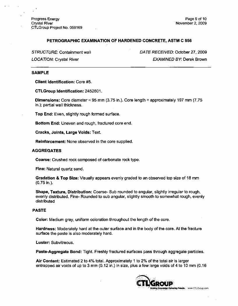
PETROGRAPHIC EXAMINATION OF HARDENED CONCRETE, ASTM C 856
STRUCTURE: Containment wall DATE RECEIVED: October 27, 2009
LOCATION: Crystal River EXAMINED BY: Derek Brown
SAMPLE
Client Identification: Core #5.
CTLGroup Identification: 2452601.
Dimensions: Core diameter = 95 mm (3.75 in.). Core length = approximately 197 mm (7.75in.); partial wall thickness.
Top End: Even, slightly rough formed surface.
Bottom End: Uneven and rough, fractured core end.
Cracks, Joints, Large Voids: Text.
Reinforcement: None observed in the core supplied.
AGGREGATES
Coarse: Crushed rock composed of carbonate rock type.
Fine: Natural quartz sand.
Gradation & Top Size: Visually appears evenly graded to an observed top size of 18 mm(0.75 in.).
Shape, Texture, Distribution: Coarse- Sub rounded to angular, slightly irregular to rough,evenly distributed. Fine- Rounded to sub angular, slightly smooth to somewhat rough, evenlydistributed
PASTE
Color: Medium gray, uniform coloration throughout the length of the core.
Hardness: Moderately hard at the outer surface and in the body of the core. At the fracturesurface the paste is also moderately hard.
Luster: Subvitreous.
Paste-Aggregate Bond: Tight. Freshly fractured surfaces pass through aggregate particles.
Air Content: Estimated 2 to 4% total. Approximately 1 to 2% of the total air is largerentrapped air voids of up to 3 mm (0.12 in.) in size, plus a few large voids of 4 to 10 mm (0.16
~i1CROUP9tM,~ K,,wiedg Oeeu1ngoemi

Progress Energy Page 10 of 10Crystal River November 2, 2009CTLGroup Project No. 059169
to 0.4 in.). Somewhat uneven distribution of voids. Marginally air entrained based on the verylow volume of moderate to small sized spherical air voids in the hardened cement paste.
Depth of Carbonation: 4 to 5 mm (0.16 to 0.20 in.) as measured from the outer surface.Negligible when measured from the inner fractured core surface.
Calcium Hydroxide*: Estimated 6 to 12% of small to medium sized crystals evenlydistributed throughout the paste, and around aggregate to paste interfaces. Estimation of thevolume is difficult due to the presence of calcite fines in the cement paste.
Residual Portland Cement Clinker Particles*: Estimated 4 to 8%. Some large cementparticles, particularly belite clusters, of up to 0.15 mm in size suggest a portland cement asproduced more than 30 years ago.
Supplementary Cementitious Materials*: None observed by the core supplied.
Secondary Deposits: None observed either in the body of the core and or near the fracturesurface.
MICROCRACKING: A small number of medium length (5 to 10 mm), randomly orientatedmicrocracks are evenly distributed throughout the body of the core. At the fractured end of thecore there was no observed increase in microcracking relative to the body of the core.
ESTIMATED WATER-CEMENT RATIO: Moderate to moderately high (0.50 to 0.60) butestimation may be biased upwards due to the well advanced degree of hydration / apparent oldage of the concrete.
MISCELLANEOUS:
1. Water droplets applied to freshly fractured surfaces were somewhat slowly absorbed bythe hardened cement paste.
2. Some small areas of the inner fractured surface of the core, as received, exhibit a thinwhite haze of efflorescence-like substance suggesting leaching of lime in solution fromwithin the core, or alternatively, moisture on or flowing past the fractured surface at thedelamination position within the wall.
3. A moderate volume of fine calcite particles is present within the hardened cement paste,most likely from coarse aggregate crusher fines.
percent by volume of paste
.... g . . ...~s A w. ! wwwCTLGioup.cofn

.NfJ11M a kIWI VV
sed 81No es0
REPORTED TO:PROJECT:Concrete Sup pler:Arc/.Englnoor:
FLORIDA POWER CORP.CRYSTAL RIVER PLANT UNIT NO. 3West Coast Concrte, Inc.Gllbert Assoc., Inc.I K_ jaas
.1 7
Dalle 22 Time Loaded Class Eý Mau OwTwdc No. Load No. P- Cu. Yds.--d C2101"10Cu.. Cu. YdLJf 2JLF kbistuie: F. .1. -k %4X•L. Lbs;, C.A. us.
CammIt (TWpe)C.A. (Sie.-dV-
(Sze )
Ossip SML. WtL
Total2.
IF.A.nDatod I4CF
IceTOWa Meon*UTotal waleRev. d Whoan SOW
Adj. B"tc IL
OW LbsL _ _ Gals.Lbs.___ C Ls
4L~________GALs
I
Finish .7 ev -- Diff. -0 R (10 M")
Sipiwe of Bath Plot In~ector e.~
Tmdk. g-!2Total Rev.- (300 VAIL)
Agied Tp ~-OJ-.- OF Concete TM -.r OF ¶ M (1411)
Wft AMdd in PlFtidd Gd/Cu. Yd.(3 kAm, "t tl. Finish: ? 011 DetfnsruceŽ- 3 W.Raft
nkwbm , --- I I ý ý

* .- P.ITTSBURGH TESTING LABORATORYPlITTSUNGN, PA.
Saltim's DOWNlY
REPORTED TO; FLORIDA POWER CORP.PROJECT: CRYSTAL RIVER PLANT UNIT NO. 3Conurete Suupim: West Cesot Comete., In..Auch.Effoonew Gilbert Ass.... In..G.enera Cowruvws: J. A. Jameg
.i. /t fimeuLaski lss ~ . u 0 OIEi.TPA* lk . fLL Load ko Cu. Y 4Z..- Countylo 0-M
Co CLg Yd OF bgW~x .. A___ S LCF Lb.; C.A. A&-.. U/~Lb
Cou(Twer W
Dam uAEA Ptthieic-
PuN., me uim - m ..P...TO ATiilir LbL Til RToldumtCrn. L . Iu Tim" L'L_ _I 1*.Mm