em series models 072-360 - bosch heating and cooling · 2015-11-03 · the em series is our...
TRANSCRIPT

ur ENERGY MISER series is recognized as the most e�cient and economicalway to meet all your Coolingand Heating needs.
Available in Vertical and SplitModels from 6 to 30 tons,Horizontal Models from 6to 20 tons. The EM Seriesis our Premiere product linespeci�cally designed for Cooling Tower / Boiler Systems,Well Water Systems, and an“Extended Range Option”for Geothermal Applications.
Even during temperatureextremes, FHP equipmentmaintains its superiore�ciencies. There’ll be nonasty surprises during hotsummer days or frigid winter nights.
O
Environmentally SafeUnlike air source equipment the EM Series, when used on Well Water systems,utilizes the earth’s natural ability to conserve & store energy while helping reducepollution.
Real Cost SavingsSave from 50% to 70% in heating costs and up to 40% in cooling costs...Plus you can get low cost HOT WATER during the summer months with our HeatRecovery option.
ReliabilityWith over 30 years of experience in heat pump technology behind every FHPunit, you can be sure of a quality product that will give you many years of troublefree service.
Geothermal Low Temperature Option
UP TO
23.1EER
UP TO
5.5COP
heat
pum
ps
EM SERIES MODELS 072-360

heat pumpshttp://www.fhp-mfg.com
FHP MANUFACTURING COMPANY601 N.W. 65TH COURT • FT. LAUDERDALE, FL 33309 • PHONE: (954) 776-5471 • FAX: (800) 776-5529
VERTICAL MODELS:144, 168, 210, 240, 300, 360
970-105 Rev. 10/08
Tabulated performance data is at noted entering water temperatures and entering air conditions of 80.6˚ F DB/66.2˚F WBat ARI/ISO 13256-1 rated CFM
Shaded performance requires LOW TEMPERATURE OPTION when ordered for the EM Series to function below 50˚ F entering fluid temps
All ratings & specifications are subject to change without notice.
MODEL CFM
EM SERIES MODELS 072-360
VERTICAL MODELS:072, 096, 120
HORIZONTAL MODELS:072, 096, 120, 140, 170, 242
B
C
VERTICAL HORIZONTAL
MODEL A B C D E F
EM072 42.00 32.00 62.00 38.00 78.00 21.50 EM096 42.00 32.00 62.00 38.00 78.00 21.50 EM120 42.00 32.00 62.00 38.00 78.00 21.50 EM140 NOT AVAILABLE 42.00 82.00 25.50 EM144 80.00 32.00 62.00
NOT AVAILABLE EM168 80.00 32.00 62.00 EM170 NOT AVAILABLE 60.25 120.00 29.25 EM210 80.00 32.00 62.00
NOT AVAILABLE EM240 80.00 32.00 66.50 EM242 NOT AVAILABLE 60.25 120.00 40.00 EM300 80.00 32.00 66.50
NOT AVAILABLE EM360 80.00 32.00 86.50
DIMENSIONS
ARI / ISO 13256-1 PERFORMANCE DATAENTERING WATER TEMPERATURES
Water Loop Ground Water Ground Loop 86˚F 68˚F 59˚F 50˚F 77˚F 32˚F
CAPACITY AND EFFICIENCY DATA COOLING HEATING COOLING HEATING COOLING HEATING CAPACITY EER CAPACITY COP CAPACITY EER CAPACITY COP CAPACITY EER CAPACITY COP (WLHP) (WLHP) (WLHP) (WLHP) (GWHP) (GWHP) (GWHP) (GWHP) (GLHP) (GLHP) (GLHP) (GLHP)
EM072 2400 71,000 14.0 72,000 4.6 81,000 18.0 60,000 4.1 73,000 15.8 47,000 3.6
EM096 2800 95,000 13.2 106,000 4.7 100,000 18.0 85,000 4.1 96,000 15.0 66,000 3.5
EM120 4000 120,000 13.4 142,000 5.0 135,000 18.0 112,000 4.3 124,000 16.2 92,000 3.6
ARI ONLY RATES EQUIPMENT BELOW 130,000 BTUH THEREFORE THE MODELS BELOW ARE TESTED IN ACCORDANCE WITH ARI/ISO 13526-1 STANDARD
EM140 5000 140,000 11.5 174,000 4.2 162,000 15.6 142,000 3.9 143,000 12.3 104,000 3.2
EM144 5000 150,000 15.3 173,000 5.5 177,000 23.1 138,000 4.9 156,000 17.1 100,000 4.1
EM168 6000 174,000 13.6 196,000 4.8 188,000 19.2 150,000 4.1 175,000 14.7 112,000 3.4
EM170 6000 174,000 13.6 196,000 4.8 188,000 19.2 150,000 4.1 175,000 14.7 112,000 3.4
EM210 7000 214,000 14.0 260,000 5.0 282,000 21.7 197,000 4.4 235,000 16.4 145,000 3.8
EM240 8000 240,000 13.8 305,000 4.8 300,000 20.3 240,000 4.4 260,000 15.5 170,000 3.7
EM242 8000 240,000 13.8 305,000 4.8 300,000 20.3 240,000 4.4 260,000 15.5 170,000 3.7
EM300 10000 285,000 12.4 360,000 4.1 350,000 18.1 290,000 3.7 300,000 13.4 210,000 2.9
EM360 12000 372,000 14.4 420,000 4.2 455,000 21.5 333,000 3.8 389,000 16.0 240,000 3.2
A
E D
F
C
AB
B A

GENERALUnits shall be performance certified to ISO standard 13256-1 for Water Loop Heat Pump, Ground Water Heat Pump and Ground Loop Heat Pump applications for units up to 10 tons. Units intended for use on ground loop applications shall have an optional extended range package installed which consists of an insulated water to refrigerant heat exchanger. Units shall be Underwriter Laboratories (UL and cUL) listed for safety on all models. Each unit shall be run tested at the factory. Each unit shall be pallet mounted and stretch wrapped. The units shall be manufactured in an ISO9001:2000 certified facility.
The units shall be warranted by the manufacturer against defects in materials and workmanship for a period of one year on all parts, and 5 years on the compressor.
The units shall be designed to operate with entering fluid temperatures between 50˚F (10˚C) and 100˚F (38˚C) in cooling and between 50˚F (10˚C) and 80˚F (27˚C) in heating. With the optional factory installed extended range package units shall operate with entering fluid temperatures between 50˚F (10˚C) and 110˚F (43.3˚C) in cooling and between 25˚F (-3.9˚C) and 80˚F (27˚C) in heating.
CASING & CABINETThe cabinet shall be fabricated from heavy-gauge galvanized steel. The interior shall be insulated with ½” (12.7mm) thick, multi density, coated, glass fiber. All units shall allow sufficient service access to replace the compressors without unit removal. Two blower and two compressor compartment access panels shall be removable with supply and return ductwork in place. A duct collar shall be provided on the supply air opening of all vertical units. A 2" (50.8mm) return air filter rack/duct collar with 1" (25.4mm) thick filters shall be provided with each unit. Vertical units shall have an insulated divider panel between the air handling section and the compressor section to minimize the transmission of compressor noise, and to permit operational service testing without air bypass. Units shall have stainless steel condensate drain pan(s).
REFRIGERATION CIRCUITSAll units shall contain sealed refrigerant circuits including hermetic compressors, thermal expansion valve metering devices, finned tube air-to-refrigerant heat exchangers, refrigerant reversing valves and service ports. Compressors shall be high efficiency, designed for heat pump duty, internally spring isolated (except for scroll type compressors) for maximum sound attenuation and mounted on rubber vibration isolators. Compressor motors shall be equipped with overload protection. Refrigerant reversing valves shall be pilot operated sliding piston type with replaceable encapsulated magnetic coils energized only during the cooling cycle. The finned tube coil shall be constructed of lanced aluminum fins not exceeding fourteen fins per inch bonded to rifled copper tubes in a staggered pattern not less than three rows deep and have a 450 PSIG (3100 kPa) working pressure. Coils shall have a baked polyester enamel coating for protection against most
airbourne chemicals. Coils shall have aluminum end sheets. The coaxial water-to-refrigerant heat exchangers shall be constructed of a convoluted copper (optional cupro-nickel) inner tube and steel outer tube with a designed refrigerant working pressure of 450 PSIG (3100 kPa) and a designed water side working pressure of no less than 400 PSIG (2750 kPa).
FAN MOTOR & ASSEMBLY(S)The fan(s) shall be belt driven DWDI forward curved type with dynamically balanced wheel(s). The housing(s) and wheel(s) shall be designed for quiet low velocity operation. The fan housing(s) shall be removable from the unit without disconnecting the supply air ductwork for servicing of the fan motor(s). The fan motor(s) shall be 1725 or 3450 RPM 56 frame sealed ball bearing type. The motor(s) shall be permanently lubricated and have thermal overload protection.
ELECTRICALControls and safety devices will be factory wired and mounted within the unit. Controls shall include fan relay(s), compressor contactors, 24V transformer, reversing valve coils and a solid state lock-out control circuit (UPM). The UPM controller shall include the following features: Anti-short cycle time delay, random start, interstage delay, brown out/surge/power interruption protection, 120 second low pressure switch bypass timer, shutdown on high or low refrigerant pressure safety switch inputs, shutdown for the optional freezestat or high level condensate sensors, 24 VAC alarm output for remote fault indication, unit reset at thermostat or disconnect, ability to defeat time delays for servicing, time delay between stages and automatic intelligent reset. The UPM shall automatically reset after a safety shut down and restart the unit, if the cause of the shut down no longer exists, after the anti-short cycle and random start timers expire. Should a fault re-occur within 60 minutes after reset, then a permanent lockout will occur. A light emitting diode (LED) shall annunciate the following alarms for each refrigerant circuit: high refrigerant pressure, low refrigerant pressure, low water temperature and a high level of condensate in the drain pan (when equipped with the optional low water temperature and high level condensate sensors). The LED will display each fault condition as soon as the fault occurs. If a permanent lockout occurs, then the fault LED will display the type of fault until the unit is reset. Safety devices include a low pressure cutout set at 20 PSIG (140 kPa) for loss of charge protection (a freezestat used for loss of charge protection is not acceptable) and a high pressure cutout control set at 380 PSIG (2600 kPa). An optional energy management relay to allow unit control by an external source shall be factory installed.
PIPINGSupply, return water and condensate drain connections shall be copper or brass female pipe thread fittings and mounted flush to cabinet exterior.
EMSPECS.INDD REV: 2-04
GUIDESPECIFICATIONS
EM Series 6-30 Large Commercial

Front Return Standard Blower Orientation
OptionalBlower Orientation(979-032)
Notes: Condensate connections are 0.75" FPT on -072 through -120 and 1.25" FPT on -150 and -180. Due to continuing research and development, specifications are subject to change without notice. EMSVDGIP.P65 Rev. 07/10/07
Top Supply (FBT) Front Supply (FBF)
Optional Blower Orientation(979-032)
Rear Return Standard Blower Orientation
Top Supply (FFT) Rear Supply (FFR)
DimensionsAll Dimensions +/- 0.125"
Dimension Model -072 -096 -120 Height 62.00 62.00 62.00 Width 42.00 42.00 42.00 Depth 32.00 32.00 32.00
Condenser Connections A 14.75 14.75 15.00 B 8.50 8.50 9.00 C 2.75 2.75 3.00 Dia. (FPT) 1.00" 1.00" 1.50"
Return Air Opening D(Duct Flange) 38.00 38.00 38.00 E(Filter Rack) 40.00 40.00 40.00
Replacement Filter Size -072 through -120 20 x 34-1/2 x 1 (2 per unit)
Service Access Panel # Access To: 1 Controls, Compressors, Refrigeration Components 2 Blower & Motor 3 Blower
Single Blower Large Commercial Units
FHP Manufacturing Co.601 N.W. 65th CourtFort Lauderdale, FL 33309Phone: (954) 776-5471Fax: (800) 776-5529http://www.fhp-mfg.com
EM072-120 Vertical Dimensions

Notes: All condensate connections are 0.75" FPT. Due to continuing research and development, specifications are subject to change without notice. EMLHDGIP.P65 Rev. 06/08
072, 096 & 140 (-SLS Only)
DimensionsAll Dimensions +/- 0.125"
Dimension Model -072 -096 -120 -140 Height 21.50 21.50 21.50 25.50 Width 38.00 38.00 38.00 42.00 Depth 78.00 78.00 78.00 82.00
Return Air Dimensions A 2.00 2.00 2.00 2.00 B 20.50 20.50 20.50 24.00 C 18.50 18.50 18.50 22.00
Condenser Connections E 26.25 26.25 27.50 22.50 F 2.75 2.75 3.38 2.75 G 37.50 37.50 38.25 30.75 H 14.50 19.25 16.75 18.25 Diameter 1"FPT 1"FPT 1.25"FPT 1.50"FPT
Supply Air Dimensions (Blower Outlet) J 15.50 15.50 12.50 18.50 K 13.50 13.50 13.50 16.00 L 10.50 10.50 5.25 14.00
Replacement Filter Size 072-120 20 x 34-1/2 x 1 (2 per unit) 140 24 x 34 x 1 (2 per unit)
Service Access Panel# Access To: 1 Controls, Compressors 2 Blower & Motor 3 Compressors, Refrigeration Components
120 (-SLS Only)
FHP Manufacturing Co.601 N.W. 65th CourtFort Lauderdale, FL 33309Phone: (954) 776-5471Fax: (800) 776-5529http://www.fhp-mfg.com
EM072-140 Horizontal Dimensions

Notes: All dimensions +/- 0.125". All condensate connections are 1.25" FPT. Due to continuing research and development, specifications are subject to change without notice. EM170242HZIP.P65 Rev.1-04
EM242 SLS CONFIGURATION ONLY
EM170 SLS CONFIGURATION ONLY
DimensionsCondenser Connections
EM170 1.50"FPT EM242 2.00"FPT
Replacement Filter Size EM170 24 x 34 x 1 (2) EM242 20 x 34-1/2 x 1 (4)
Service Access Panel# Access To: 1 Controls, Compressors, Refrigeration Components 2 Blowers & Motors 3 Compressors, Refrigeration Components
FHP Manufacturing Co.601 N.W. 65th CourtFort Lauderdale, FL 33309Phone: (954) 776-5471Fax: (800) 776-5529http://www.fhp-mfg.com
EM170-242 Horizontal Dimensions

Dual Blower Large Commercial Units
Rear ReturnFront Supply(FBF)
Rear ReturnTop Supply
(FBT)
Standard BlowerOrientation
Due to continuing research and development, specifications are subject to change with out notice. EMDVDGIP.P65 Rev: 7-23-04
Standard BlowerOrientation
Optional BlowerOrientation (979-033)
Optional BlowerOrientation (979-033)Front Return
Top Supply(FFT)
Front ReturnRear Supply
(FFR)
F
DimensionsAll Dimensions +/- 0.125"
Model Height A B C D E 144 62.00 17.00 10.50 3.00 40.00 38.00 168 62.00 17.00 10.50 3.00 40.00 38.00 210 62.00 14.75 8.50 2.75 40.00 38.00 240 66.50 14.75 8.75 2.75 40.00 38.00 300 66.50 14.75 8.75 2.75 40.00 38.00 360 86.50 15.00 9.00 3.50 60.00 58.00
Model Condenser Condensate Connection Drain Diameter Diameter 144 1.50"FPT 1.25"FPT 168 1.50"FPT 1.25"FPT 210 2.00"FPT 1.25"FPT 240 2.00"FPT 1.25"FPT 300 2.00"FPT 1.25"FPT 360 2.00"FPT 1.25"FPT
Supply Air Duct Collar Location (F) Standard Blower Orientation 6.00 Optional Blower Orientation 11.00
Recommended ReplacementFilter Size (Nominal)
20 x 34-1/2 x 1 (4 per unit, 144-300)30 x 34-1/2 x 1 (4 per unit, 360)
Service Access Panel # Access To: 1 Controls, Compressors, Refrigeration Components 2 Blower & Motor 3 Blower
F
FHP Manufacturing Co.601 N.W. 65th CourtFort Lauderdale, FL 33309Phone: (954) 776-5471Fax: (800) 776-5529http://www.fhp-mfg.com
EM144-360 Vertical Dimensions

63.78 4.44 48.61 4.2 70.76 4.65 54.89 4.5 77.75 4.86 61.17 4.7 84.74 5.07 67.44 4.9 60.31 4.52 44.88 3.9 66.91 4.73 50.75 4.1 73.51 4.95 56.63 4.4 80.11 5.16 62.51 4.6 56.24 4.62 40.47 3.6 62.39 4.84 45.88 3.8 68.54 5.05 51.29 4.0 74.69 5.27 56.69 4.2
Fluid Pressure Flow Drop (GPM) (FOH) (PSIG) 10 6.0 2.6 12 8.3 3.6 14 11.0 4.8 16 14.0 6.1 18 17.3 7.5
208/230-1-60 -1 14.7 74.0 7.5 1 - - 40.6 50 208/230-3-60 -3 9.3 68.0 3.6 1 - - 24.5 35 460-3-60 -4 5.0 36.0 1.8 1 - - 13.1 15
Electrical Elect. Characteristics Symbol
0.10 0.20 0.30 0.40 0.50 0.60 0.70 0.80 0.90 1.00 1.10 1.20
CAPACITY DATA All performance at 2,300 CFM and 16.0 GPM
ELECTRICAL SPECIFICATIONS
BLOWER PERFORMANCE
COOLING HEATING
Available External Static Pressure (Inches of Water, Gauge. Wet Coil and Filter Included)
Motor Sheave Closed - - - - - - - - 2420 2160 1900 1700 1/2 Open - - 2980 2800 2610 2400 2100 1800 - - - - Open 2780 2590 2350 2050 1780 - - - - - - -
Water Loop Ground Water Ground Loop (Ext. Range Required)
Cooling Heating Cooling Heating Cooling Heating Capacity EER Capacity COP Capacity EER Capacity COP Capacity EER Capacity COP 71,000 14.0 72,000 4.6 81,000 18.0 60,000 4.1 73,000 15.8 47,000 3.6
ISO 13256-1 CERTIFIED PERFORMANCE DATA Rated at 2,300 CFM and 16.0 GPM
Refrigerant: R-22 Air Coil Square Rows Tube Fins/ Feet Deep O.D. Inch 7.00 3 3/8 14 Water Coil Type Work Press Coaxial 450 psig Blower Size Compr Type 12x12 BD Reciprocating Net Weight Ship Weight 631 lbs 676 lbs
MECHANICAL SPECIFICATIONS
Units are complete packages featuring 2 stage operation and containing compressors, reversing valve, expansion valve metering devices, and heat exchangers. Also included are safety controls: Overload protection for motors, high and low refrigerant pressure switches and a solid state lock-out circuit.
Extended range option includes insulated water coils.
Performance based on ARI/ISO rated air flow, fluid flow and voltage. For conditions other than rated, consult the FHP EAD selection software. Due to variations in installation actual performance may vary marginally from tabulated values.
As a result of continuing research and development, specifications are subject to change without notice.
EM072ip6 mod2 Rev: 6-02
FLUID PRESSURE DROP
71.38 47.15 0.66 4.38 86.34 16.3 68.21 45.43 0.67 4.57 83.81 14.9 65.03 43.85 0.67 4.76 81.28 13.7 60.27 41.71 0.69 5.04 77.49 12.0 55.51 39.76 0.72 5.33 73.69 10.4 76.48 56.38 0.74 4.41 91.53 17.3 73.09 54.32 0.74 4.60 88.78 15.9 69.69 52.44 0.75 4.79 86.03 14.6 64.59 49.89 0.77 5.07 81.90 12.7 59.50 47.56 0.80 5.36 77.78 11.1 83.95 62.24 0.74 4.44 99.11 18.9 80.22 59.98 0.75 4.63 96.04 17.3 76.50 57.91 0.76 4.83 92.97 15.9 70.92 55.10 0.78 5.11 88.36 13.9 65.33 52.53 0.80 5.40 83.75 12.1 91.41 68.17 0.75 4.48 106.69 20.4 87.36 65.69 0.75 4.67 103.30 18.7 83.31 63.43 0.76 4.86 99.91 17.1 77.24 60.35 0.78 5.15 94.82 15.0 71.16 57.55 0.81 5.44 89.73 13.1
EFT Range (Standard) EFT Range (Ext. Range Option)50oF to 80oF 25oF to 80oF
EFT Range (Standard) EFT Range (Ext. Range Option)50oF to 100oF 45oF to 110oF
25o 30o 60o
40o
25o
30o 70o
40o
25o
30o 80o
40o
LOW TEMP HEATING 45.40 3.92 32.01 3.4 48.83 4.03 35.08 3.6 55.68 4.24 41.22 3.9 42.95 3.99 29.32 3.2 46.19 4.10 32.20 3.3 52.66 4.31 37.95 3.6 40.08 4.08 26.15 2.9 43.09 4.19 28.80 3.0 49.11 4.40 34.08 3.3
Extended Range Option RequiredAntifreeze Required
2 STAGE PACKAGED UNITS
SPECIFICATION DATA SHEETFHP MANUFACTURING HIGH-EFFICIENCY WATER SOURCE HEAT PUMPS
EM072ENERGY-MISER
FHP MANUFACTURING COMPANY601 N.W. 65th Court - Fort Lauderdale, FL 33309
Phone: (954) 776-5471 - Fax: (800) 776-5529http://www.fhp-mfg.com
Entering Entering Heat Fluid Air Total Power of Temp. Temp. Capacity Input Abs. COP (oF) (oF) (MBtuH) (kW) (MBtuH) 50o 60o
60o
70o
80o
50o
60o 70o
70o
80o
50o
60o 80o
70o
80o
Compressor(x2) Blower Loop Pump Min. Max. Circuit Fuse/ RLA LRA FLA HP FLA HP Amps Breaker
Entering Entering Sensible Heat Fluid Air Total Sensible to Power of Temp. Temp. Capacity Capacity Total Input Reject EER (oF) (oF) (MBtuH) (MBtuH) Ratio (kW) (MBtuH) 50o
60o 70odb 70o 61owb 85o
100o
50o
60o 75odb 70o 63owb 85o
100o
50o
60o 80odb 70o 67owb 85o
100o
50o
60o 85odb 70o 71owb 85o
100o
91.30 6.16 70.27 4.3 102.53 6.46 80.49 4.7 113.76 6.76 90.70 4.9 124.98 7.05 100.92 5.2 86.33 6.27 64.92 4.0 96.94 6.58 74.50 4.3 107.55 6.88 84.07 4.6 118.15 7.18 93.65 4.8 80.49 6.41 58.61 3.7 90.37 6.72 67.44 3.9 100.25 7.03 76.26 4.2 110.13 7.34 85.08 4.4
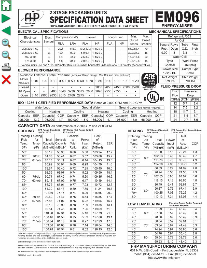
Fluid Pressure Flow Drop (GPM) (FOH) (PSIG) 12 5.7 2.4 14 7.5 3.2 18 11.7 5.1 21 15.5 6.7 24 19.7 8.5
208/230-1-60 -1 20.5 115.0 10.2/12.3 1-1/2 / 2 - - 56.3/58.4 70 208/230-3-60 -3 12.4 90.0 5.0/6.4 1-1/2 / 2 - - 32.9/34.3 45 460-3-60 -4 6.4 44.0 2.5/3.2 1-1/2 / 2 - - 16.9/17.6 20 575-3-60 -5 4.8 34.0 2.0/2.0 1-1/2 / 2 - - 12.8/12.8 15
*Vertical units use one 1-1/2 HP motor (first value) while horizontal units use one 2 HP motor (second value)
Electrical Elect. Characteristics Symbol
0.10 0.20 0.30 0.40 0.50 0.60 0.70 0.80 0.90 1.00 1.10 1.20
CAPACITY DATA All performance at 2,800CFM and 21.0 GPM
ELECTRICAL SPECIFICATIONS
BLOWER PERFORMANCE
COOLING HEATING
Available External Static Pressure (Inches of Water, Gauge. Wet Coil and Filter Included)
Motor Sheave Closed - - - - - - - 2800 2650 2450 2300 2200 1/2 Open - - 3480 3340 3230 3075 2880 2690 2555 2355 - - Open 3110 2965 2835 2615 2460 2275 - - - - - -
Water Loop Ground Water Ground Loop (Ext. Range Required)
Cooling Heating Cooling Heating Cooling Heating Capacity EER Capacity COP Capacity EER Capacity COP Capacity EER Capacity COP 95,000 13.2 106,000 4.7 100,000 18.0 85,000 4.1 96,000 15.0 66,000 3.5
ISO 13256-1 CERTIFIED PERFORMANCE DATA Rated at 2,800 CFM and 21.0 GPM
Refrigerant: R-22 Air Coil Square Rows Tube Fins/ Feet Deep O.D. Inch 9.00 3 3/8 14 Water Coil Type Work Press Coaxial 450 psig Blower Size Compr Type 12x12 BD Scroll Net Weight Ship Weight 679 lbs 704 lbs
MECHANICAL SPECIFICATIONS
Units are complete packages featuring 2 stage operation and containing compressors, reversing valve, expansion valve metering devices, and heat exchangers. Also included are safety controls: Overload protection for motors, high and low refrigerant pressure switches and a solid state lock-out circuit.
Extended range option includes insulated water coils.
Performance based on ARI/ISO rated air flow, fluid flow and voltage. For conditions other than rated, consult the FHP EAD selection software. Due to variations in installation actual performance may vary marginally from tabulated values.
As a result of continuing research and development, specifications are subject to change without notice.
EM096ip6 mod2 Rev: 6-02
FLUID PRESSURE DROP
86.19 56.93 0.66 5.00 103.24 17.2 84.68 56.41 0.67 5.57 103.68 15.2 83.18 56.11 0.67 6.14 104.13 13.6 80.92 56.04 0.69 6.99 104.79 11.6 78.67 56.40 0.72 7.85 105.45 10.0 92.35 68.07 0.74 5.02 109.50 18.4 90.74 67.45 0.74 5.60 109.85 16.2 89.13 67.09 0.75 6.17 110.19 14.4 86.72 67.01 0.77 7.03 110.72 12.3 84.30 67.43 0.80 7.89 111.24 10.7 101.36 75.15 0.74 5.06 118.65 20.0 99.60 74.47 0.75 5.64 118.85 17.7 97.83 74.07 0.76 6.22 119.06 15.7 95.19 73.99 0.78 7.09 119.38 13.4 92.54 74.45 0.80 7.96 119.69 11.6 110.38 82.31 0.75 5.10 127.79 21.6 108.46 81.56 0.75 5.69 127.86 19.1 106.54 81.13 0.76 6.27 127.93 17.0 103.66 81.03 0.78 7.14 128.04 14.5 100.78 81.54 0.81 8.02 128.15 12.6
EFT Range (Standard) EFT Range (Ext. Range Option)50oF to 80oF 25oF to 80oF
EFT Range (Standard) EFT Range (Ext. Range Option)50oF to 100oF 45oF to 110oF
25o 30o 60o
40o
25o
30o 70o
40o
25o
30o 80o
40o
LOW TEMP HEATING 61.99 5.42 43.49 3.4 67.50 5.57 48.49 3.6 78.50 5.87 58.49 3.9 58.64 5.52 39.81 3.1 63.84 5.67 44.49 3.3 74.24 5.97 53.86 3.6 54.70 5.64 35.46 2.8 59.54 5.79 39.78 3.0 69.23 6.10 48.40 3.3
Extended Range Option RequiredAntifreeze Required
2 STAGE PACKAGED UNITS
SPECIFICATION DATA SHEETFHP MANUFACTURING HIGH-EFFICIENCY WATER SOURCE HEAT PUMPS
EM096ENERGY-MISER
FHP MANUFACTURING COMPANY601 N.W. 65th Court - Fort Lauderdale, FL 33309
Phone: (954) 776-5471 - Fax: (800) 776-5529http://www.fhp-mfg.com
Entering Entering Heat Fluid Air Total Power of Temp. Temp. Capacity Input Abs. COP (oF) (oF) (MBtuH) (kW) (MBtuH) 50o 60o
60o
70o
80o
50o
60o 70o
70o
80o
50o
60o 80o
70ov
80o
Compressor(x2) Blower Loop Pump Min. Max. Circuit Fuse/ RLA LRA FLA HP FLA HP Amps Breaker
Entering Entering Sensible Heat Fluid Air Total Sensible to Power of Temp. Temp. Capacity Capacity Total Input Reject EER (oF) (oF) (MBtuH) (MBtuH) Ratio (kW) (MBtuH) 50o
60o 70odb 70o 61owb 85o
100o
50o
60o 75odb 70o 63owb 85o
100o
50o
60o 80odb 70o 67owb 85o
100o
50o
60o 85odb 70o 71owb 85o
100o

123.35 8.10 95.71 4.5 137.33 8.33 108.92 4.8 151.32 8.55 122.12 5.2 165.31 8.78 135.33 5.5 116.65 8.24 88.53 4.1 129.87 8.47 100.94 4.5 143.08 8.71 113.36 4.8 156.29 8.94 125.78 5.1 108.79 8.42 80.06 3.8 121.09 8.66 91.55 4.1 133.40 8.90 103.04 4.4 145.70 9.13 114.53 4.7
Fluid Pressure Flow Drop (GPM) (FOH) (PSIG) 16 4.8 2.1 20 7.2 3.1 24 10.0 4.3 28 13.2 5.7 32 16.8 7.3
208/230-1-60 -1 27.9 170.0 12.3 2 - - 75.1 100 208/230-3-60 -3 17.3 123.0 6.4/9.0 2 / 3 - - 45.3/47.9 60 460-3-60 -4 7.1 49.5 3.2/4.5 2 / 3 - - 19.2/20.5 25 575-3-60 -5 5.8 40.0 2.0/3.7 2 / 3 - - 15.1/16.8 20
*Vertical units use one 2 HP motor (first value) while horizontal units use one 3 HP motor & 2 12x9 blowers (second value)
Electrical Elect. Characteristics Symbol
0.10 0.20 0.30 0.40 0.50 0.60 0.70 0.80 0.90 1.00 1.10 1.20
CAPACITY DATA All performance at 4,000CFM and 28.0 GPM
ELECTRICAL SPECIFICATIONS
BLOWER PERFORMANCE
COOLING HEATING
Available External Static Pressure (Inches of Water, Gauge. Wet Coil and Filter Included)
Motor Sheave Closed - - - - - - - - 4400 4150 3830 3600 1/2 Open - - - 4660 4490 4240 3950 3600 3000 - - - Open 4680 4490 4270 4000 3700 3370 - - - - - -
Water Loop Ground Water Ground Loop (Ext. Range Required)
Cooling Heating Cooling Heating Cooling Heating Capacity EER Capacity COP Capacity EER Capacity COP Capacity EER Capacity COP 120,000 13.4 142,000 5.0 135,000 18.0 112,000 4.3 124,000 16.2 92,000 3.6
ISO 13256-1 CERTIFIED PERFORMANCE DATA Rated at 4,000 CFM and 28.0 GPM
Refrigerant: R-22 Air Coil Square Rows Tube Fins/ Feet Deep O.D. Inch 9.00 3 3/8 14 Water Coil Type Work Press Coaxial 450 psig Blower Size* Compr Type 15x15 BD Scroll Net Weight Ship Weight 875 lbs 900 lbs
MECHANICAL SPECIFICATIONS
Units are complete packages featuring 2 stage operation and containing compressors, reversing valve, expansion valve metering devices, and heat exchangers. Also included are safety controls: Overload protection for motors, high and low refrigerant pressure switches and a solid state lock-out circuit.
Extended range option includes insulated water coils.
Performance based on ARI/ISO rated air flow, fluid flow and voltage. For conditions other than rated, consult the FHP EAD selection software. Due to variations in installation actual performance may vary marginally from tabulated values.
As a result of continuing research and development, specifications are subject to change without notice.
EM120ip6 mod2 Rev: 6-02
FLUID PRESSURE DROP
118.42 78.11 0.66 7.03 142.42 16.8 113.78 75.67 0.67 7.47 139.26 15.2 109.13 73.48 0.67 7.90 136.09 13.8 102.16 70.60 0.69 8.55 131.34 11.9 95.19 68.09 0.72 9.20 126.60 10.3 126.91 93.46 0.74 7.07 151.05 17.9 121.94 90.54 0.74 7.51 147.56 16.2 116.97 87.94 0.75 7.94 144.08 14.7 109.50 84.51 0.77 8.60 138.85 12.7 102.04 81.52 0.80 9.25 133.63 11.0 139.34 103.22 0.74 7.12 163.65 19.6 133.88 100.01 0.75 7.56 159.70 17.7 128.43 97.14 0.76 8.01 155.75 16.0 120.25 93.36 0.78 8.67 149.82 13.9 112.07 90.06 0.80 9.33 143.90 12.0 151.76 113.08 0.75 7.18 176.26 21.1 145.82 109.57 0.75 7.62 171.84 19.1 139.89 106.43 0.76 8.07 167.42 17.3 130.99 102.29 0.78 8.73 160.80 15.0 122.10 98.68 0.81 9.40 154.17 13.0
EFT Range (Standard) EFT Range (Ext. Range Option)50oF to 80oF 25oF to 80oF
EFT Range (Standard) EFT Range (Ext. Range Option)50oF to 100oF 45oF to 110oF
25o 30o 60o
40o
25o
30o 70o
40o
25o
30o 80o
40o
LOW TEMP HEATING 86.65 7.53 60.97 3.4 93.51 7.64 67.43 3.6 107.22 7.87 80.36 4.0 81.98 7.66 55.84 3.1 88.46 7.78 61.92 3.3 101.41 8.01 74.08 3.7 76.49 7.82 49.80 2.9 82.53 7.94 55.42 3.0 94.59 8.18 66.67 3.4
Extended Range Option RequiredAntifreeze Required
2 STAGE PACKAGED UNITS
SPECIFICATION DATA SHEETFHP MANUFACTURING HIGH-EFFICIENCY WATER SOURCE HEAT PUMPS
EM120ENERGY-MISER
FHP MANUFACTURING COMPANY601 N.W. 65th Court - Fort Lauderdale, FL 33309
Phone: (954) 776-5471 - Fax: (800) 776-5529http://www.fhp-mfg.com
Entering Entering Heat Fluid Air Total Power of Temp. Temp. Capacity Input Abs. COP (oF) (oF) (MBtuH) (kW) (MBtuH) 50o 60o
60o
70o
80o
50o
60o 70o
70o
80o
50o
60o 80o
70o
80o
Compressor(x2) Blower Loop Pump Min. Max. Circuit Fuse/ RLA LRA FLA HP FLA HP Amps Breaker
Entering Entering Sensible Heat Fluid Air Total Sensible to Power of Temp. Temp. Capacity Capacity Total Input Reject EER (oF) (oF) (MBtuH) (MBtuH) Ratio (kW) (MBtuH) 50o
60o 70odb 70o 61owb 85o
100o
50o
60o 75odb 70o 63owb 85o
100o
50o
60o 80odb 70o 67owb 85o
100o
50o
60o 85odb 70o 71owb 85o
100o
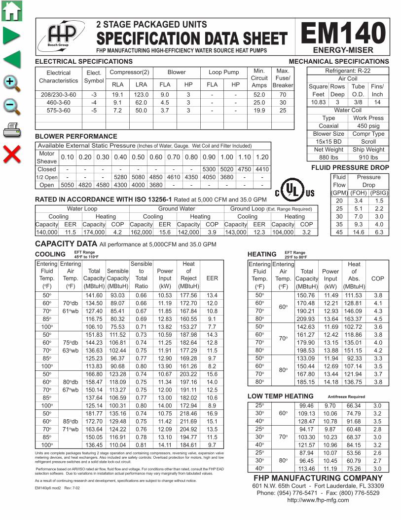
150.76 11.49 111.53 3.8 170.48 12.21 128.81 4.1 190.21 12.93 146.09 4.3 209.93 13.64 163.37 4.5 142.63 11.69 102.72 3.6 161.27 12.42 118.86 3.8 179.90 13.15 135.01 4.0 198.53 13.88 151.15 4.2 133.09 11.94 92.33 3.3 150.44 12.69 107.14 3.5 167.80 13.44 121.94 3.7 185.15 14.18 136.75 3.8
Fluid Pressure Flow Drop (GPM) (FOH) (PSIG) 20 3.4 1.5 25 5.1 2.2 30 7.0 3.0 35 9.3 4.0 45 14.6 6.3
208/230-3-60 -3 19.1 123.0 9.0 3 - - 52.0 70 460-3-60 -4 9.1 62.0 4.5 3 - - 25.0 30 575-3-60 -5 7.2 50.0 3.7 3 - - 19.9 25
Electrical Elect. Characteristics Symbol
0.10 0.20 0.30 0.40 0.50 0.60 0.70 0.80 0.90 1.00 1.10 1.20
CAPACITY DATA All performance at 5,000CFM and 35.0 GPM
ELECTRICAL SPECIFICATIONS
BLOWER PERFORMANCE
COOLING HEATING
Available External Static Pressure (Inches of Water, Gauge. Wet Coil and Filter Included)
Motor Sheave Closed - - - - - - - - 5300 5020 4750 4410 1/2 Open - - - 5280 5080 4850 4610 4350 4050 3680 - - Open 5050 4820 4580 4300 4000 3680 - - - - - -
Water Loop Ground Water Ground Loop (Ext. Range Required)
Cooling Heating Cooling Heating Cooling Heating Capacity EER Capacity COP Capacity EER Capacity COP Capacity EER Capacity COP 140,000 11.5 174,000 4.2 162,000 15.6 142,000 3.9 143,000 12.3 104,000 3.2
RATED IN ACCORDANCE WITH ISO 13256-1 Rated at 5,000 CFM and 35.0 GPM
Refrigerant: R-22 Air Coil Square Rows Tube Fins/ Feet Deep O.D. Inch 10.83 3 3/8 14 Water Coil Type Work Press Coaxial 450 psig Blower Size Compr Type 15x15 BD Scroll Net Weight Ship Weight 880 lbs 910 lbs
MECHANICAL SPECIFICATIONS
Units are complete packages featuring 2 stage operation and containing compressors, reversing valve, expansion valve metering devices, and heat exchangers. Also included are safety controls: Overload protection for motors, high and low refrigerant pressure switches and a solid state lock-out circuit.
Performance based on ARI/ISO rated air flow, fluid flow and voltage. For conditions other than rated, consult the FHP EAD selection software. Due to variations in installation actual performance may vary marginally from tabulated values.
As a result of continuing research and development, specifications are subject to change without notice.
EM140ip6 mod2 Rev: 7-02
FLUID PRESSURE DROP
141.60 93.03 0.66 10.53 177.56 13.4 134.50 89.07 0.66 11.19 172.70 12.0 127.40 85.41 0.67 11.85 167.84 10.8 116.75 80.32 0.69 12.83 160.55 9.1 106.10 75.53 0.71 13.82 153.27 7.7 151.83 111.52 0.73 10.59 187.98 14.3 144.23 106.81 0.74 11.25 182.64 12.8 136.63 102.44 0.75 11.91 177.29 11.5 125.23 96.37 0.77 12.90 169.28 9.7 113.83 90.68 0.80 13.90 161.26 8.2 166.80 123.28 0.74 10.67 203.22 15.6 158.47 118.09 0.75 11.34 197.16 14.0 150.14 113.27 0.75 12.00 191.11 12.5 137.64 106.59 0.77 13.00 182.02 10.6 125.14 100.31 0.80 14.00 172.94 8.9 181.77 135.16 0.74 10.75 218.46 16.9 172.70 129.48 0.75 11.42 211.69 15.1 163.64 124.22 0.76 12.09 204.92 13.5 150.05 116.91 0.78 13.10 194.77 11.5 136.45 110.04 0.81 14.11 184.61 9.7
EFT Range 25oF to 80oF
EFT Range 45oF to 110oF
25o 30o 60o
40o
25o
30o 70o
40o
25o
30o 80o
40o
LOW TEMP HEATING 99.46 9.70 66.34 3.0 109.13 10.06 74.79 3.2 128.47 10.78 91.68 3.5 94.17 9.87 60.48 2.8 103.30 10.23 68.37 3.0 121.57 10.96 84.15 3.2 87.94 10.07 53.56 2.6 96.45 10.45 60.79 2.7 113.46 11.19 75.26 3.0
Antifreeze Required
2 STAGE PACKAGED UNITS
SPECIFICATION DATA SHEETFHP MANUFACTURING HIGH-EFFICIENCY WATER SOURCE HEAT PUMPS
EM140ENERGY-MISER
FHP MANUFACTURING COMPANY601 N.W. 65th Court - Fort Lauderdale, FL 33309
Phone: (954) 776-5471 - Fax: (800) 776-5529http://www.fhp-mfg.com
Entering Entering Heat Fluid Air Total Power of Temp. Temp. Capacity Input Abs. COP (oF) (oF) (MBtuH) (kW) (MBtuH) 50o 60o
60o
70o
80o
50o
60o 70o
70o
80o
50o
60o 80o
70o
80o
Compressor(2) Blower Loop Pump Min. Max. Circuit Fuse/ RLA LRA FLA HP FLA HP Amps Breaker
Entering Entering Sensible Heat Fluid Air Total Sensible to Power of Temp. Temp. Capacity Capacity Total Input Reject EER (oF) (oF) (MBtuH) (MBtuH) Ratio (kW) (MBtuH) 50o
60o 70odb 70o 61owb 85o
100o
50o
60o 75odb 70o 63owb 85o
100o
50o
60o 80odb 70o 67owb 85o
100o
50o
60o 85odb 70o 71owb 85o
100o

149.92 9.64 117.01 4.6 170.54 10.21 135.69 4.9 191.15 10.78 154.37 5.2 211.77 11.34 173.05 5.5 141.97 9.80 108.54 4.2 161.45 10.37 126.04 4.6 180.92 10.95 143.55 4.8 200.40 11.53 161.05 5.1 132.63 9.98 98.56 3.9 150.77 10.57 114.68 4.2 168.91 11.16 130.80 4.4 187.05 11.76 146.93 4.7
Fluid Pressure Flow Drop (GPM) (FOH) (PSIG) 20 3.4 1.5 25 5.1 2.2 30 7.0 3.0 35 9.3 4.0 50 17.6 7.6
208/230-3-60 -3 19.1 123.0 5.0 1 1/2 - - 53.0 70 460-3-60 -4 9.1 62.0 2.5 1 1/2 - - 25.5 35 575-3-60 -5 7.2 50.0 2.0 1 1/2 - - 20.2 25
Electrical Elect. Characteristics Symbol
0.10 0.20 0.30 0.40 0.50 0.60 0.70 0.80 0.90 1.00 1.10 1.20
CAPACITY DATA All performance at 5,000 CFM and 35.0 GPM
ELECTRICAL SPECIFICATIONS
BLOWER PERFORMANCE
COOLING HEATING
Available External Static Pressure (Inches of Water, Gauge. Wet Coil and Filter Included)
Motor Sheave Closed - - - - - - 7120 6920 6530 6080 5660 5120 1/2 Open - - - 6860 6530 6120 5780 5380 4880 4090 - - Open 6770 6300 5880 5430 4970 4340 3750 - - - - -
Water Loop Ground Water Ground Loop (Ext. Range Required)
Cooling Heating Cooling Heating Cooling Heating Capacity EER Capacity COP Capacity EER Capacity COP Capacity EER Capacity COP 150,000 15.3 173,000 5.5 177,000 23.1 138,000 4.9 156,000 17.1 100,000 4.1
RATED IN ACCORDANCE WITH ISO 13256-1 Rated at 5,000 CFM and 35.0 GPM
Refrigerant: R-22 Air Coil Square Rows Tube Fins/ Feet Deep O.D. Inch 14.00 3 3/8 14 Water Coil Type Work Press Coaxial 450 psig Blower Size Compr Type 12x12 BD Scroll Net Weight Ship Weight 1,050 lbs 1,140 lbs
MECHANICAL SPECIFICATIONS
Units are complete packages featuring 2 stage operation and containing compressors, reversing valve, expansion valve metering devices, and heat exchangers. Also included are safety controls: Overload protection for motors, high and low refrigerant pressure switches and a solid state lock-out circuit.
Extended range option includes insulated water coils.
Performance based on ARI/ISO rated air flow, fluid flow and voltage. For conditions other than rated, consult the FHP EAD selection software. Due to variations in installation actual performance may vary marginally from tabulated values.
As a result of continuing research and development, specifications are subject to change without notice.
EM144ip6 mod2 Rev: 7-02
FLUID PRESSURE DROP
153.77 100.35 0.65 8.42 182.52 18.3 145.19 95.48 0.66 9.21 176.62 15.8 136.61 90.92 0.67 9.99 170.71 13.7 123.74 84.48 0.68 11.17 161.86 11.1 110.87 78.32 0.71 12.35 153.01 9.0 165.03 120.68 0.73 8.46 193.91 19.5 155.84 114.89 0.74 9.25 187.42 16.8 146.66 109.45 0.75 10.04 180.93 14.6 132.88 101.78 0.77 11.23 171.19 11.8 119.10 94.45 0.79 12.41 161.46 9.6 181.49 133.62 0.74 8.52 210.56 21.3 171.42 127.23 0.74 9.31 203.21 18.4 161.35 121.24 0.75 10.11 195.86 16.0 146.25 112.79 0.77 11.31 184.83 12.9 131.14 104.70 0.80 12.50 173.80 10.5 197.95 146.69 0.74 8.57 227.22 23.1 187.00 139.70 0.75 9.38 219.00 19.9 176.04 133.15 0.76 10.18 210.79 17.3 159.61 123.91 0.78 11.38 198.47 14.0 143.18 115.06 0.80 12.59 186.15 11.4
EFT Range (Standard) EFT Range (Ext. Range Option)50oF to 80oF 25oF to 80oF
EFT Range (Standard) EFT Range (Ext. Range Option)50oF to 100oF 45oF to 110oF
25o 30o 60o
40o
25o
30o 70o
40o
25o
30o 80o
40o
LOW TEMP HEATING 96.45 8.23 68.37 3.4 106.56 8.51 77.51 3.7 126.77 9.08 95.79 4.1 91.45 8.35 62.94 3.2 101.00 8.64 71.51 3.4 120.09 9.22 88.63 3.8 85.58 8.51 56.54 2.9 94.47 8.80 64.43 3.1 112.25 9.39 80.19 3.5
Extended Range Option RequiredAntifreeze Required
2 STAGE PACKAGED UNITS
SPECIFICATION DATA SHEETFHP MANUFACTURING HIGH-EFFICIENCY WATER SOURCE HEAT PUMPS
EM144ENERGY-MISER
FHP MANUFACTURING COMPANY601 N.W. 65th Court - Fort Lauderdale, FL 33309
Phone: (954) 776-5471 - Fax: (800) 776-5529http://www.fhp-mfg.com
Entering Entering Heat Fluid Air Total Power of Temp. Temp. Capacity Input Abs. COP (oF) (oF) (MBtuH) (kW) (MBtuH) 50o 60o
60o
70o
80o
50o
60o 70o
70o
80o
50o
60o 80o
70o
80o
Compressor(x2) Blower Loop Pump Min. Max. Circuit Fuse/ RLA LRA FLA HP FLA HP Amps Breaker
Entering Entering Sensible Heat Fluid Air Total Sensible to Power of Temp. Temp. Capacity Capacity Total Input Reject EER (oF) (oF) (MBtuH) (MBtuH) Ratio (kW) (MBtuH) 50o
60o 70odb 70o 61owb 85o
100o
50o
60o 75odb 70o 63owb 85o
100o
50o
60o 80odb 70o 67owb 85o
100o
50o
60o 85odb 70o 71owb 85o
100o

164.54 11.91 123.90 4.0 188.07 12.54 145.27 4.4 211.60 13.17 166.65 4.7 235.14 13.81 188.02 5.0 155.74 12.11 114.42 3.8 177.97 12.75 134.45 4.1 200.20 13.40 154.48 4.4 222.43 14.04 174.51 4.6 145.40 12.35 103.24 3.4 166.10 13.01 121.69 3.7 186.81 13.67 140.14 4.0 207.51 14.33 158.59 4.2
Fluid Pressure Flow Drop (GPM) (FOH) (PSIG) 22 4.0 1.7 27 5.8 2.5 32 7.9 3.4 42 12.9 5.6 52 18.9 8.2
208/230-3-60 -3 21.8 158.0 6.4 2 - - 61.9 80 460-3-60 -4 10.3 79.0 3.2 2 - - 29.6 40 575-3-60 -5 9.0 65.0 2.0 2 - - 24.3 30
Electrical Elect. Characteristics Symbol
0.10 0.20 0.30 0.40 0.50 0.60 0.70 0.80 0.90 1.00 1.10 1.20
CAPACITY DATA All performance at 6,000 CFM and 42.0 GPM
ELECTRICAL SPECIFICATIONS
BLOWER PERFORMANCE
COOLING HEATING
Available External Static Pressure (Inches of Water, Gauge. Wet Coil and Filter Included)
Motor Sheave Closed - - - - - - 7200 6940 6560 6150 5710 5140 1/2 Open - - 7200 6930 6580 6200 5800 5450 4920 - - - Open 6780 6350 5970 5540 5050 4510 - - - - - -
Water Loop Ground Water Ground Loop (Ext. Range Required)
Cooling Heating Cooling Heating Cooling Heating Capacity EER Capacity COP Capacity EER Capacity COP Capacity EER Capacity COP 174,000 13.6 196,000 4.8 188,000 19.2 150,000 4.1 175,000 14.7 112,000 3.4
RATED IN ACCORDANCE WITH ISO 13256-1 Rated at 6,000 CFM and 42.0 GPM
Refrigerant: R-22 Air Coil Square Rows Tube Fins/ Feet Deep O.D. Inch 14.00 3 3/8 14 Water Coil Type Work Press Coaxial 450 psig Blower Size Compr Type 12x12 BD Scroll Net Weight Ship Weight 1,090 lbs 1,180 lbs
MECHANICAL SPECIFICATIONS
Units are complete packages featuring 2 stage operation and containing compressors, reversing valve, expansion valve metering devices, and heat exchangers. Also included are safety controls: Overload protection for motors, high and low refrigerant pressure switches and a solid state lock-out circuit.
Extended range option includes insulated water coils.
Performance based on ARI/ISO rated air flow, fluid flow and voltage. For conditions other than rated, consult the FHP EAD selection software. Due to variations in installation actual performance may vary marginally from tabulated values.
As a result of continuing research and development, specifications are subject to change without notice.
EM168ip6 mod2 Rev: 7-02
FLUID PRESSURE DROP
160.30 104.96 0.65 9.87 194.00 16.2 155.84 102.89 0.66 10.98 193.32 14.2 151.39 101.22 0.67 12.08 192.63 12.5 144.70 99.34 0.69 13.74 191.60 10.5 138.01 98.13 0.71 15.40 190.57 9.0 171.96 126.03 0.73 9.92 205.83 17.3 167.19 123.57 0.74 11.04 204.85 15.1 162.41 121.56 0.75 12.15 203.87 13.4 155.26 119.33 0.77 13.81 202.41 11.2 148.10 117.89 0.80 15.48 200.94 9.6 189.01 139.43 0.74 9.99 223.12 18.9 183.78 136.71 0.74 11.12 221.72 16.5 178.55 134.51 0.75 12.24 220.31 14.6 170.70 132.05 0.77 13.92 218.20 12.3 162.85 130.46 0.80 15.60 216.09 10.4 206.06 152.96 0.74 10.07 240.42 20.5 200.37 149.99 0.75 11.20 238.58 17.9 194.68 147.58 0.76 12.33 236.75 15.8 186.15 144.89 0.78 14.02 234.00 13.3 177.61 143.16 0.81 15.72 231.25 11.3
EFT Range (Standard) EFT Range (Ext. Range Option)50oF to 80oF 25oF to 80oF
EFT Range (Standard) EFT Range (Ext. Range Option)50oF to 100oF 45oF to 110oF
25o 30o 60o
40o
25o
30o 70o
40o
25o
30o 80o
40o
LOW TEMP HEATING 103.64 10.33 68.39 2.9 115.17 10.64 78.85 3.2 138.24 11.28 99.76 3.6 98.19 10.50 62.37 2.7 109.09 10.82 72.17 3.0 130.89 11.46 91.77 3.3 91.80 10.70 55.27 2.5 101.95 11.03 64.29 2.7 122.25 11.69 82.34 3.1
Extended Range Option RequiredAntifreeze Required
2 STAGE PACKAGED UNITS
SPECIFICATION DATA SHEETFHP MANUFACTURING HIGH-EFFICIENCY WATER SOURCE HEAT PUMPS
EM168ENERGY-MISER
FHP MANUFACTURING COMPANY601 N.W. 65th Court - Fort Lauderdale, FL 33309
Phone: (954) 776-5471 - Fax: (800) 776-5529http://www.fhp-mfg.com
Entering Entering Heat Fluid Air Total Power of Temp. Temp. Capacity Input Abs. COP (oF) (oF) (MBtuH) (kW) (MBtuH) 50o 60o
60o
70o
80o
50o
60o 70o
70o
80o
50o
60o 80o
70o
80o
Compressor(x2) Blower(x2) Loop Pump Min. Max. Circuit Fuse/ RLA LRA FLA HP FLA HP Amps Breaker
Entering Entering Sensible Heat Fluid Air Total Sensible to Power of Temp. Temp. Capacity Capacity Total Input Reject EER (oF) (oF) (MBtuH) (MBtuH) Ratio (kW) (MBtuH) 50o
60o 70odb 70o 61owb 85o
100o
50o
60o 75odb 70o 63owb 85o
100o
50o
60o 80odb 70o 67owb 85o
100o
50o
60o 85odb 70o 71owb 85o
100o

165.50 12.04 124.42 4.0 189.34 12.71 145.97 4.4 213.19 13.38 167.52 4.7 237.03 14.05 189.07 4.9 156.62 12.24 114.84 3.7 179.15 12.93 135.03 4.1 201.68 13.61 155.22 4.3 224.21 14.30 175.41 4.6 146.19 12.49 103.55 3.4 167.17 13.19 122.14 3.7 188.15 13.89 140.73 4.0 209.13 14.60 159.32 4.2
Fluid Pressure Flow Drop (GPM) (FOH) (PSIG) 22 4.0 1.7 27 5.8 2.5 32 7.9 3.4 42 12.9 5.6 52 18.9 8.2
208/230-3-60 -3 21.8 158.0 6.4 2 - - 61.9 80 460-3-60 -4 10.3 79.0 3.2 2 - - 29.6 40 575-3-60 -5 9.0 65.0 2.0 2 - - 24.3 30
Electrical Elect. Characteristics Symbol
0.10 0.20 0.30 0.40 0.50 0.60 0.70 0.80 0.90 1.00 1.10 1.20
CAPACITY DATA All performance at 6,000 CFM and 42.0 GPM
ELECTRICAL SPECIFICATIONS
BLOWER PERFORMANCE
COOLING HEATING
Available External Static Pressure (Inches of Water, Gauge. Wet Coil and Filter Included)
Motor Sheave Closed - - - - - - - - 5960 5850 5410 4940 1/2 Open - - - - - 6000 5590 5160 4670 - - - Open - 6050 5770 5340 4850 4310 - - - - - -
Water Loop Ground Water Ground Loop (Ext. Range Required)
Cooling Heating Cooling Heating Cooling Heating Capacity EER Capacity COP Capacity EER Capacity COP Capacity EER Capacity COP 174,000 13.6 196,000 4.8 188,000 19.2 150,000 4.1 175,000 14.7 112,000 3.4
RATED IN ACCORDANCE WITH ISO 13256-1 Rated at 6,000 CFM and 42.0 GPM
Refrigerant: R-22 Air Coil Square Rows Tube Fins/ Feet Deep O.D. Inch 11.00 3 3/8 14 Water Coil Type Work Press Coaxial 450 psig Blower Size Compr Type 12x12 BD Scroll Net Weight Ship Weight 1,520 lbs 1,620 lbs
MECHANICAL SPECIFICATIONS
Units are complete packages featuring 2 stage operation and containing compressors, reversing valve, expansion valve metering devices, and heat exchangers. Also included are safety controls: Overload protection for motors, high and low refrigerant pressure switches and a solid state lock-out circuit.
Extended range option includes insulated water coils.
Performance based on ARI/ISO rated air flow, fluid flow and voltage. For conditions other than rated, consult the FHP EAD selection software. Due to variations in installation actual performance may vary marginally from tabulated values.
As a result of continuing research and development, specifications are subject to change without notice.
EM170ip6 mod2 Rev: 7-02
FLUID PRESSURE DROP
159.59 100.66 0.63 10.08 194.00 15.8 154.96 98.55 0.64 11.25 193.34 13.8 150.33 96.81 0.64 12.41 192.68 12.1 143.38 94.81 0.66 14.16 191.70 10.1 136.44 93.42 0.68 15.90 190.71 8.6 171.17 120.83 0.71 10.13 205.75 16.9 166.21 118.32 0.71 11.31 204.79 14.7 161.25 116.24 0.72 12.48 203.83 12.9 153.82 113.86 0.74 14.23 202.40 10.8 146.38 112.21 0.77 15.99 200.96 9.2 188.10 133.66 0.71 10.21 222.94 18.4 182.67 130.89 0.72 11.39 221.54 16.0 177.24 128.60 0.73 12.57 220.13 14.1 169.09 125.97 0.75 14.34 218.03 11.8 160.94 124.15 0.77 16.11 215.92 10.0 205.04 146.62 0.72 10.28 240.13 19.9 199.13 143.59 0.72 11.47 238.28 17.4 193.22 141.09 0.73 12.66 236.43 15.3 184.35 138.21 0.75 14.45 233.66 12.8 175.49 136.22 0.78 16.23 230.89 10.8
EFT Range (Standard) EFT Range (Ext. Range Option)50oF to 80oF 25oF to 80oF
EFT Range (Standard) EFT Range (Ext. Range Option)50oF to 100oF 45oF to 110oF
25o 30o 60o
40o
25o
30o 70o
40o
25o
30o 80o
40o
LOW TEMP HEATING 103.81 10.36 68.46 2.9 115.50 10.69 79.00 3.2 138.87 11.36 100.09 3.6 98.33 10.53 62.40 2.7 109.38 10.87 72.27 2.9 131.46 11.56 92.02 3.3 91.90 10.74 55.24 2.5 102.19 11.09 64.33 2.7 122.76 11.79 82.51 3.1
Extended Range Option RequiredAntifreeze Required
2 STAGE PACKAGED UNITS
SPECIFICATION DATA SHEETFHP MANUFACTURING HIGH-EFFICIENCY WATER SOURCE HEAT PUMPS
EM170ENERGY-MISER
FHP MANUFACTURING COMPANY601 N.W. 65th Court - Fort Lauderdale, FL 33309
Phone: (954) 776-5471 - Fax: (800) 776-5529http://www.fhp-mfg.com
Entering Entering Heat Fluid Air Total Power of Temp. Temp. Capacity Input Abs. COP (oF) (oF) (MBtuH) (kW) (MBtuH) 50o 60o
60o
70o
80o
50o
60o 70o
70o
80o
50o
60o 80o
70o
80o
Compressor(x2) Blower(x2) Loop Pump Min. Max. Circuit Fuse/ RLA LRA FLA HP FLA HP Amps Breaker
Entering Entering Sensible Heat Fluid Air Total Sensible to Power of Temp. Temp. Capacity Capacity Total Input Reject EER (oF) (oF) (MBtuH) (MBtuH) Ratio (kW) (MBtuH) 50o
60o 70odb 70o 61owb 85o
100o
50o
60o 75odb 70o 63owb 85o
100o
50o
60o 80odb 70o 67owb 85o
100o
50o
60o 85odb 70o 71owb 85o
100o

219.21 14.99 168.03 4.3 251.76 16.10 196.80 4.6 284.32 17.22 225.56 4.8 316.87 18.33 254.32 5.1 207.57 15.24 155.57 4.0 238.32 16.37 182.46 4.3 269.07 17.50 209.35 4.5 299.83 18.63 236.24 4.7 193.89 15.53 140.87 3.7 222.53 16.69 165.56 3.9 251.17 17.85 190.25 4.1 279.81 19.01 214.94 4.3
Fluid Pressure Flow Drop (GPM) (FOH) (PSIG) 30 5.88 2.55 40 9.87 4.27 50 14.75 6.38 60 20.48 8.86 70 27.03 11.70
208/230-3-60 -3 28.8 195.0 5.0 1 1/2 - - 74.8 100 460-3-60 -4 14.7 85.0 2.5 1 1/2 - - 38.1 50 575-3-60 -5 8.4 63.0 2.0 1 1/2 - - 22.9 30
Electrical Elect. Characteristics Symbol
0.10 0.20 0.30 0.40 0.50 0.60 0.70 0.80 0.90 1.00 1.10 1.20
CAPACITY DATA All performance at 7,000 CFM and 50.0 GPM
ELECTRICAL SPECIFICATIONS
BLOWER PERFORMANCE
COOLING HEATING
Available External Static Pressure (Inches of Water, Gauge. Wet Coil and Filter Included)
Motor Sheave Closed - - - - - - - - - - 7800 7500 1/2 Open - - - - - 8600 8200 7600 6900 5240 - - Open 8840 8400 8000 7560 7000 6400 - - - - - -
Water Loop Ground Water Ground Loop (Ext. Range Required)
Cooling Heating Cooling Heating Cooling Heating Capacity EER Capacity COP Capacity EER Capacity COP Capacity EER Capacity COP 214,000 14.0 260,000 5.0 282,000 21.7 197,000 4.4 235,000 16.4 145,000 3.8
RATED IN ACCORDANCE WITH ISO 13256-1 Rated at 7,000 CFM and 50.0 GPM
Refrigerant: R-22 Air Coil Square Rows Tube Fins/ Feet Deep O.D. Inch 18.10 3 3/8 14 Water Coil Type Work Press Coaxial 450 psig Blower Size Compr Type 15x15 BD Scroll Net Weight Ship Weight 1,170 lbs 1,260 lbs
MECHANICAL SPECIFICATIONS
Units are complete packages featuring 2 stage operation and containing compressors, reversing valve, expansion valve metering devices, and heat exchangers. Also included are safety controls: Overload protection for motors, high and low refrigerant pressure switches and a solid state lock-out circuit.
Extended range option includes insulated water coils.
Performance based on ARI/ISO rated air flow, fluid flow and voltage. For conditions other than rated, consult the FHP EAD selection software. Due to variations in installation actual performance may vary marginally from tabulated values.
As a result of continuing research and development, specifications are subject to change without notice.
EM210ip6 mod2 Rev: 7-06
FLUID PRESSURE DROP
255.57 167.30 0.65 14.17 303.93 18.0 234.52 154.65 0.66 14.99 285.69 15.6 213.48 142.38 0.67 15.82 267.45 13.5 181.91 124.32 0.68 17.05 240.09 10.7 150.34 106.13 0.71 18.28 212.73 8.2 274.16 200.90 0.73 14.24 322.77 19.3 251.63 185.83 0.74 15.07 303.06 16.7 229.10 171.22 0.75 15.89 283.35 14.4 195.31 149.70 0.77 17.13 253.79 11.4 161.52 128.04 0.79 18.37 224.23 8.8 301.36 222.27 0.74 14.34 350.30 21.0 276.66 205.66 0.74 15.17 328.45 18.2 251.96 189.56 0.75 16.01 306.60 15.7 214.92 165.85 0.77 17.26 273.82 12.5 177.88 141.97 0.80 18.51 241.04 9.6 328.55 243.86 0.74 14.44 377.83 22.8 301.69 225.70 0.75 15.28 353.84 19.8 274.83 208.09 0.76 16.12 329.84 17.1 234.53 182.15 0.78 17.38 293.85 13.5 194.23 156.04 0.80 18.64 257.85 10.4
EFT Range (Standard) EFT Range (Ext. Range Option)50oF to 80oF 25oF to 80oF
EFT Range (Standard) EFT Range (Ext. Range Option)50oF to 100oF 45oF to 110oF
25o 30o 60o
40o
25o
30o 70o
40o
25o
30o 80o
40o
LOW TEMP HEATING 135.13 12.22 93.42 3.2 151.08 12.77 107.49 3.5 183.00 13.88 135.61 3.9 128.12 12.41 85.77 3.0 143.19 12.97 98.92 3.2 173.34 14.10 125.21 3.6 119.88 12.64 76.75 2.8 133.92 13.22 88.82 3.0 162.00 14.37 112.94 3.3
Extended Range Option RequiredAntifreeze Required
2 STAGE PACKAGED UNITS
SPECIFICATION DATA SHEETFHP MANUFACTURING HIGH-EFFICIENCY WATER SOURCE HEAT PUMPS
EM210ENERGY-MISER
FHP MANUFACTURING COMPANY601 N.W. 65th Court - Fort Lauderdale, FL 33309
Phone: (954) 776-5471 - Fax: (800) 776-5529http://www.fhp-mfg.com
Entering Entering Heat Fluid Air Total Power of Temp. Temp. Capacity Input Abs. COP (oF) (oF) (MBtuH) (kW) (MBtuH) 50o 60o
60o
70o
80o
50o
60o 70o
70o
80o
50o
60o 80o
70o
80o
Compressor(x2) Blower(x2) Loop Pump Min. Max. Circuit Fuse/ RLA LRA FLA HP FLA HP Amps Breaker
Entering Entering Sensible Heat Fluid Air Total Sensible to Power of Temp. Temp. Capacity Capacity Total Input Reject EER (oF) (oF) (MBtuH) (MBtuH) Ratio (kW) (MBtuH) 50o
60o 70odb 70o 61owb 85o
100o
50o
60o 75odb 70o 63owb 85o
100o
50o
60o 80odb 70o 67owb 85o
100o
50o
60o 85odb 70o 71owb 85o
100o

258.92 18.20 196.78 4.2 297.14 19.62 230.19 4.4 335.36 21.03 263.59 4.7 373.58 22.44 297.00 4.9 245.09 18.51 181.92 3.9 281.19 19.95 213.12 4.1 317.30 21.38 244.32 4.3 353.41 22.82 275.52 4.5 228.84 18.88 164.40 3.6 262.47 20.35 193.01 3.8 296.09 21.82 221.61 4.0 329.72 23.29 250.22 4.1
Fluid Pressure Flow Drop (GPM) (FOH) (PSIG) 30 3.7 1.6 40 6.2 2.7 50 9.3 4.0 60 12.9 5.6 75 19.2 8.3
208/230-3-60 -3 28.6 179.0 6.4 2 - - 77.5 100 460-3-60 -4 12.0 90.0 3.2 2 - - 33.4 45 575-3-60 -5 9.7 72.0 2.0 2 - - 25.8 35
Electrical Elect. Characteristics Symbol
0.10 0.20 0.30 0.40 0.50 0.60 0.70 0.80 0.90 1.00 1.10 1.20
CAPACITY DATA All performance at 8,000 CFM and 60.0 GPM
ELECTRICAL SPECIFICATIONS
BLOWER PERFORMANCE
COOLING HEATING
Available External Static Pressure (Inches of Water, Gauge. Wet Coil and Filter Included)
Motor Sheave Closed - - - - - - - - 9000 8800 8330 7660 1/2 Open - - - - 9320 8980 8480 7900 7200 6000 - - Open 9360 8980 8540 8000 7400 6740 - - - - - -
Water Loop Ground Water Ground Loop (Ext. Range Required)
Cooling Heating Cooling Heating Cooling Heating Capacity EER Capacity COP Capacity EER Capacity COP Capacity EER Capacity COP 240,000 13.8 305,000 4.8 300,000 20.3 240,000 4.4 260,000 15.5 170,000 3.7
RATED IN ACCORDANCE WITH ISO 13256-1 Rated at 8,000 CFM and 60.0 GPM
Refrigerant: R-22 Air Coil Square Rows Tube Fins/ Feet Deep O.D. Inch 18.10 3 3/8 14 Water Coil Type Work Press Coaxial 450 psig Blower Size Compr Type 15x15 BD Scroll Net Weight Ship Weight 1,250 lbs 1,340 lbs
MECHANICAL SPECIFICATIONS
Units are complete packages featuring 2 stage operation and containing compressors, reversing valve, expansion valve metering devices, and heat exchangers. Also included are safety controls: Overload protection for motors, high and low refrigerant pressure switches and a solid state lock-out circuit.
Extended range option includes insulated water coils.
Performance based on ARI/ISO rated air flow, fluid flow and voltage. For conditions other than rated, consult the FHP EAD selection software. Due to variations in installation actual performance may vary marginally from tabulated values.
As a result of continuing research and development, specifications are subject to change without notice.
EM240VTip6 mod2 Rev: 7-02
FLUID PRESSURE DROP
268.72 176.01 0.66 15.78 322.58 17.0 250.34 165.22 0.66 16.76 307.53 14.9 231.95 154.90 0.67 17.73 292.47 13.1 204.38 139.96 0.68 19.19 269.89 10.6 176.81 125.19 0.71 20.66 247.30 8.6 288.25 211.30 0.73 15.86 342.38 18.2 268.57 198.45 0.74 16.84 326.05 15.9 248.89 186.15 0.75 17.82 309.72 14.0 219.38 168.35 0.77 19.29 285.22 11.4 189.86 150.77 0.79 20.76 260.73 9.1 316.82 233.75 0.74 15.97 371.33 19.8 295.24 219.59 0.74 16.96 353.13 17.4 273.67 206.03 0.75 17.95 334.94 15.2 241.32 186.41 0.77 19.43 307.64 12.4 208.96 167.03 0.80 20.92 280.35 10.0 345.38 256.42 0.74 16.09 400.28 21.5 321.92 240.93 0.75 17.08 380.22 18.8 298.45 226.11 0.76 18.08 360.15 16.5 263.25 204.66 0.78 19.57 330.06 13.4 228.06 183.46 0.80 21.07 299.96 10.8
EFT Range (Standard) EFT Range (Ext. Range Option)50oF to 80oF 25oF to 80oF
EFT Range (Standard) EFT Range (Ext. Range Option)50oF to 100oF 45oF to 110oF
25o 30o 60o
40o
25o
30o 70o
40o
25o
30o 80o
40o
LOW TEMP HEATING 160.16 14.68 110.07 3.2 178.90 15.38 126.40 3.4 216.37 16.79 159.05 3.8 151.78 14.91 100.88 3.0 169.48 15.63 116.13 3.2 204.88 17.07 146.62 3.5 141.93 15.20 90.05 2.7 158.41 15.94 104.02 2.9 191.38 17.41 131.97 3.2
Extended Range Option RequiredAntifreeze Required
2 STAGE PACKAGED UNITS
SPECIFICATION DATA SHEETFHP MANUFACTURING HIGH-EFFICIENCY WATER SOURCE HEAT PUMPS
EM240ENERGY-MISER
FHP MANUFACTURING COMPANY601 N.W. 65th Court - Fort Lauderdale, FL 33309
Phone: (954) 776-5471 - Fax: (800) 776-5529http://www.fhp-mfg.com
Entering Entering Heat Fluid Air Total Power of Temp. Temp. Capacity Input Abs. COP (oF) (oF) (MBtuH) (kW) (MBtuH) 50o 60o
60o
70o
80o
50o
60o 70o
70o
80o
50o
60o 80o
70o
80o
Compressor(x2) Blower(x2) Loop Pump Min. Max. Circuit Fuse/ RLA LRA FLA HP FLA HP Amps Breaker
Entering Entering Sensible Heat Fluid Air Total Sensible to Power of Temp. Temp. Capacity Capacity Total Input Reject EER (oF) (oF) (MBtuH) (MBtuH) Ratio (kW) (MBtuH) 50o
60o 70odb 70o 61owb 85o
100o
50o
60o 75odb 70o 63owb 85o
100o
50o
60o 80odb 70o 67owb 85o
100o
50o
60o 85odb 70o 71owb 85o
100o

257.23 18.17 195.23 4.1 295.24 19.60 228.36 4.4 333.25 21.03 261.49 4.6 371.26 22.46 294.61 4.8 243.46 18.47 180.42 3.9 279.38 19.93 211.36 4.1 315.29 21.39 242.29 4.3 351.20 22.85 273.23 4.5 227.29 18.85 162.97 3.5 260.74 20.34 191.32 3.8 294.18 21.83 219.67 3.9 327.62 23.32 248.02 4.1
Fluid Pressure Flow Drop (GPM) (FOH) (PSIG) 30 3.7 1.6 40 6.2 2.7 50 9.3 4.0 60 12.9 5.6 75 19.2 8.3
208/230-3-60 -3 28.6 179.0 6.4 2 - - 77.5 100 460-3-60 -4 12.0 90.0 3.2 2 - - 33.4 45 575-3-60 -5 9.7 72.0 2.0 2 - - 25.8 35
Electrical Elect. Characteristics Symbol
0.10 0.20 0.30 0.40 0.50 0.60 0.70 0.80 0.90 1.00 1.10 1.20
CAPACITY DATA All performance at 8,000 CFM and 60.0 GPM
ELECTRICAL SPECIFICATIONS
BLOWER PERFORMANCE
COOLING HEATING
Available External Static Pressure (Inches of Water, Gauge. Wet Coil and Filter Included)
Motor Sheave Closed - - - - - - - - - - 8120 7500 1/2 Open - - - - - - 8280 7700 7000 5800 - - Open - - 8340 7800 7200 6540 - - - - - -
Water Loop Ground Water Ground Loop (Ext. Range Required)
Cooling Heating Cooling Heating Cooling Heating Capacity EER Capacity COP Capacity EER Capacity COP Capacity EER Capacity COP 240,000 13.8 305,000 4.8 300,000 20.3 240,000 4.4 260,000 15.5 170,000 3.7
RATED IN ACCORDANCE WITH ISO 13256-1 Rated at 8,000 CFM and 60.0 GPM
Refrigerant: R-22 Air Coil Square Rows Tube Fins/ Feet Deep O.D. Inch 15.30 3 3/8 14 Water Coil Type Work Press Coaxial 450 psig Blower Size Compr Type 15x15 BD Scroll Net Weight Ship Weight 1,655 lbs 1,755 lbs
MECHANICAL SPECIFICATIONS
Units are complete packages featuring 2 stage operation and containing compressors, reversing valve, expansion valve metering devices, and heat exchangers. Also included are safety controls: Overload protection for motors, high and low refrigerant pressure switches and a solid state lock-out circuit.
Extended range option includes insulated water coils.
Performance based on ARI/ISO rated air flow, fluid flow and voltage. For conditions other than rated, consult the FHP EAD selection software. Due to variations in installation actual performance may vary marginally from tabulated values.
As a result of continuing research and development, specifications are subject to change without notice.
EM240HZip6 mod2 Rev: 7-02
FLUID PRESSURE DROP
267.36 173.08 0.65 15.63 320.69 17.1 248.64 162.18 0.65 16.60 305.29 15.0 229.91 151.74 0.66 17.57 289.89 13.1 201.82 136.57 0.68 19.04 266.79 10.6 173.73 121.54 0.70 20.50 243.69 8.5 286.76 207.71 0.72 15.70 340.36 18.3 266.71 194.73 0.73 16.69 323.66 16.0 246.67 182.28 0.74 17.67 306.96 14.0 216.60 164.22 0.76 19.14 281.91 11.3 186.53 146.32 0.78 20.61 256.87 9.1 315.13 229.73 0.73 15.82 369.11 19.9 293.16 215.43 0.73 16.81 350.51 17.4 271.18 201.71 0.74 17.79 331.91 15.2 238.22 181.80 0.76 19.28 304.01 12.4 205.26 162.08 0.79 20.76 276.11 9.9 343.50 251.98 0.73 15.93 397.87 21.6 319.60 236.34 0.74 16.93 377.37 18.9 295.70 221.34 0.75 17.92 356.86 16.5 259.84 199.56 0.77 19.42 326.11 13.4 223.99 177.99 0.79 20.91 295.36 10.7
EFT Range (Standard) EFT Range (Ext. Range Option)50oF to 80oF 25oF to 80oF
EFT Range (Standard) EFT Range (Ext. Range Option)50oF to 100oF 45oF to 110oF
25o 30o 60o
40o
25o
30o 70o
40o
25o
30o 80o
40o
LOW TEMP HEATING 159.03 14.59 109.23 3.2 177.66 15.31 125.42 3.4 214.92 16.74 157.80 3.8 150.67 14.83 100.07 3.0 168.28 15.56 115.19 3.2 203.48 17.01 145.42 3.5 140.86 15.12 89.27 2.7 157.26 15.86 103.12 2.9 190.05 17.35 130.82 3.2
Extended Range Option RequiredAntifreeze Required
2 STAGE PACKAGED UNITS
SPECIFICATION DATA SHEETFHP MANUFACTURING HIGH-EFFICIENCY WATER SOURCE HEAT PUMPS
EM242ENERGY-MISER
FHP MANUFACTURING COMPANY601 N.W. 65th Court - Fort Lauderdale, FL 33309
Phone: (954) 776-5471 - Fax: (800) 776-5529http://www.fhp-mfg.com
Entering Entering Heat Fluid Air Total Power of Temp. Temp. Capacity Input Abs. COP (oF) (oF) (MBtuH) (kW) (MBtuH) 50o 60o
60o
70o
80o
50o
60o 70o
70o
80o
50o
60o 80o
70o
80o
Compressor(x2) Blower(x2) Loop Pump Min. Max. Circuit Fuse/ RLA LRA FLA HP FLA HP Amps Breaker
Entering Entering Sensible Heat Fluid Air Total Sensible to Power of Temp. Temp. Capacity Capacity Total Input Reject EER (oF) (oF) (MBtuH) (MBtuH) Ratio (kW) (MBtuH) 50o
60o 70odb 70o 61owb 85o
100o
50o
60o 75odb 70o 63owb 85o
100o
50o
60o 80odb 70o 67owb 85o
100o
50o
60o 85odb 70o 71owb 85o
100o
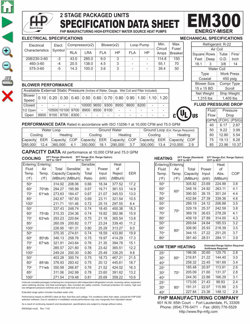
Available External Static Pressure (Inches of Water, Gauge. Wet Coil and Filter Included)
Blower Speed Closed - - - - 10000 9650 9300 8950 8600 8200 - - 1/2 Open - 10500 10100 9700 8900 8500 8100 - - - - - Open 9900 9100 8700 8300 - - - - - - - -
305.82 23.69 224.99 3.8 348.16 24.92 263.11 4.1 390.50 26.15 301.24 4.4 432.84 27.39 339.36 4.6 289.19 24.12 206.88 3.5 329.19 25.37 242.59 3.8 369.19 26.63 278.29 4.1 409.19 27.89 314.00 4.3 269.64 24.64 185.53 3.2 306.90 25.93 218.39 3.5 344.15 27.22 251.25 3.7 381.40 28.51 284.11 3.9
Fluid Pressure Flow Drop (GPM) (FOH) (PSIG) 40 6.17 2.67 50 9.22 3.99 60 12.80 5.54 75 19.13 8.28 85 23.96 10.37
208/230-3-60 -3 43.0 285.0 9.0 3 - - 114.8 150 460-3-60 -4 20.5 138.0 4.5 3 - - 55.1 70 575-3-60 -5 14.3 100.0 3.6 3 - - 39.4 50
Electrical Elect. Characteristics Symbol
0.10 0.20 0.30 0.40 0.50 0.60 0.70 0.80 0.90 1.00 1.10 1.20
CAPACITY DATA All performance at 10,000 CFM and 75.0 GPM
ELECTRICAL SPECIFICATIONS
BLOWER PERFORMANCE
COOLING HEATING
Water Loop Ground Water Ground Loop (Ext. Range Required)
Cooling Heating Cooling Heating Cooling Heating Capacity EER Capacity COP Capacity EER Capacity COP Capacity EER Capacity COP 285,000 12.4 360,000 4.1 350,000 18.1 290,000 3.7 300,000 13.4 210,000 2.9
PERFORMANCE DATA Rated in accordance with ISO 13256-1 at 10,000 CFM and 75.0 GPM
Refrigerant: R-22 Air Coil Square Rows Tube Fins/ Feet Deep O.D. Inch 18.1 3 3/8 14 Water Coil Type Work Press Coaxial 450 psig Blower Size Compr Type 15 x 15 BD Scroll Net Weight Ship Weight 1,315 lbs 1,405 lbs
MECHANICAL SPECIFICATIONS
Units are complete packages containing two compressors with independent refirgeration circuits, reversing valves, expansion valve metering devices, and heat exchangers. Also included are safety controls: Overload protection for motors, high and low refrigerant pressure switches and a solid state lock-out circuit.
Extended range option includes insulated water coils.
Performance based on ARI/ISO rated air flow, fluid flow and voltage. For conditions other than rated, consult the FHP EAD selection software. Due to variations in installation actual performance may vary marginally from tabulated values.
As a result of continuing research and development, specifications are subject to change without notice.
EM300ip6 mod2 Rev: 7-02
FLUID PRESSURE DROP
314.92 208.06 0.66 18.34 377.52 17.2 294.27 195.99 0.67 19.71 361.53 14.9 273.63 184.47 0.67 21.07 345.53 13.0 242.67 167.83 0.69 23.11 321.54 10.5 211.71 151.46 0.72 25.15 297.55 8.4 337.43 248.74 0.74 18.45 400.38 18.3 315.33 234.36 0.74 19.82 382.96 15.9 293.23 220.64 0.75 21.18 365.54 13.8 260.09 200.82 0.77 23.24 339.40 11.2 226.95 181.31 0.80 25.29 313.27 9.0 370.35 274.61 0.74 18.59 433.80 19.9 346.13 258.76 0.75 19.97 414.29 17.3 321.91 243.64 0.76 21.35 394.78 15.1 285.57 221.80 0.78 23.42 365.51 12.2 249.24 200.30 0.80 25.49 336.25 9.8 403.28 300.74 0.75 18.73 467.21 21.5 376.93 283.42 0.75 20.12 445.61 18.7 350.58 266.87 0.76 21.52 424.02 16.3 311.06 242.99 0.78 23.60 391.62 13.2 271.54 219.48 0.81 25.69 359.22 10.6
EFT Range (Standard) EFT Range (Ext. Range Option)50oF to 80oF 25oF to 80oF
EFT Range (Standard) EFT Range (Ext. Range Option)50oF to 100oF 45oF to 110oF
25o 30o 60o
40o
25o
30o 70o
40o
25o
30o 80o
40o
LOW TEMP HEATING 196.06 20.60 125.75 2.8 216.81 21.22 144.40 3.0 258.32 22.45 181.69 3.4 185.48 20.97 113.91 2.6 205.09 21.60 131.37 2.8 244.30 22.86 166.29 3.1 173.05 21.43 99.93 2.4 191.31 22.07 115.99 2.5 227.84 23.36 148.12 2.9
Extended Range Option RequiredAntifreeze Required
2 STAGE PACKAGED UNITS
SPECIFICATION DATA SHEETFHP MANUFACTURING HIGH-EFFICIENCY WATER SOURCE HEAT PUMPS
EM300ENERGY-MISER
FHP MANUFACTURING COMPANY601 N.W. 65th Court - Fort Lauderdale, FL 33309
Phone: (954) 776-5471 - Fax: (800) 776-5529http://www.fhp-mfg.com
Entering Entering Heat Fluid Air Total Power of Temp. Temp. Capacity Input Abs. COP (oF) (oF) (MBtuH) (kW) (MBtuH) 50o 60o
60o
70o
80o
50o
60o 70o
70o
80o
50o
60o 80o
70o
80o
Compressor(x2) Blower(x2) Loop Pump Min. Max. Circuit Fuse/ RLA LRA FLA HP FLA HP Amps Breaker
Entering Entering Sensible Heat Fluid Air Total Sensible to Power of Temp. Temp. Capacity Capacity Total Input Reject EER (oF) (oF) (MBtuH) (MBtuH) Ratio (kW) (MBtuH) 50o
60o 70odb 70o 61owb 85o
100o
50o
60o 75odb 70o 63owb 85o
100o
50o
60o 80odb 70o 67owb 85o
100o
50o
60o 85odb 70o 71owb 85o
100o

Available External Static Pressure (Inches of Water, Gauge. Wet Coil and Filter Included)
Blower Speed Closed - - - - - - - - - - 12900 10800 1/2 Open - - - - - 13050 11850 10350 7500 - - - Open 12200 11575 10950 9600 7800 - - - - - - -
366.97 30.73 262.10 3.5 417.85 32.73 306.14 3.7 468.73 34.74 350.17 4.0 519.61 36.74 394.21 4.1 347.76 31.21 241.24 3.3 395.83 33.25 282.34 3.5 443.90 35.30 323.43 3.7 491.97 37.34 364.52 3.9 325.19 31.80 216.64 3.0 369.96 33.90 254.27 3.2 414.73 35.99 291.90 3.4 459.49 38.08 329.53 3.5
Fluid Pressure Flow Drop (GPM) (FOH) (PSIG) 50 8.5 3.7 70 15.6 6.8 80 19.8 8.6 90 24.5 10.6 100 29.6 12.8
208/230-3-60 -3 52.6 425.0 12.2 5 - - 142.8 175 460-3-60 -4 23.7 187.0 6.1 5 - - 65.5 80 575-3-60 -5 20.5 148.0 5.4 5 - - 57.0 80
Electrical Elect. Characteristics Symbol
0.20 0.30 0.40 0.60 0.80 1.00 1.20 1.40 1.60 1.80 2.00 2.20
CAPACITY DATA All performance at 12,000 CFM and 90.0 GPM
ELECTRICAL SPECIFICATIONS
BLOWER PERFORMANCE
COOLING HEATING
Water Loop Ground Water Ground Loop (Ext. Range Required)
Cooling Heating Cooling Heating Cooling Heating Capacity EER Capacity COP Capacity EER Capacity COP Capacity EER Capacity COP 372,000 14.4 420,000 4.2 455,000 21.5 333,000 3.8 389,000 16 240,000 3.2
PERFORMANCE DATA Rated in accordance with ISO 13256-1 at 12,000 CFM and 90.0 GPM
Refrigerant: R-22 Air Coil Square Rows Tube Fins/ Feet Deep O.D. Inch 27.0 3 3/8 14 Water Coil Type Work Press Coaxial 450 psig Blower Size Compr Type 15 x 15 BD Scroll Net Weight Ship Weight 1,600 lbs 1,700 lbs
MECHANICAL SPECIFICATIONS
Entering Entering Sensible Heat Fluid Air Total Sensible to Power of Temp. Temp. Capacity Capacity Total Input Reject EER (oF) (oF) (MBtuH) (MBtuH) Ratio (kW) (MBtuH) 50o
60o 70odb 70o 61owb 85o
100o
50o
60o 75odb 70o 63owb 85o
100o
50o
60o 80odb 70o 67owb 85o
100o
50o
60o 85odb 70o 71owb 85o
100o
Units are complete packages containing two compressors with independent refirgeration circuits, reversing valves, expansion valve metering devices, and heat exchangers. Also included are safety controls: Overload protection for motors, high and low refrigerant pressure switches and a solid state lock-out circuit.
Extended range option includes insulated water coils.
Performance based on ARI/ISO rated air flow, fluid flow and voltage. For conditions other than rated, consult the FHP EAD selection software. Due to variations in installation actual performance may vary marginally from tabulated values.
As a result of continuing research and development, specifications are subject to change without notice.
EM360ip6 mod2 Rev: 8-06
FLUID PRESSURE DROP
397.02 257.84 0.65 23.62 477.63 16.8 370.82 242.58 0.65 25.33 457.26 14.6 344.62 228.05 0.66 27.04 436.90 12.7 305.32 207.12 0.68 29.60 406.35 10.3 266.02 186.59 0.70 32.16 375.80 8.3 426.34 310.82 0.73 23.73 507.31 18.0 398.29 292.64 0.73 25.44 485.14 15.7 370.25 275.33 0.74 27.16 462.96 13.6 328.18 250.41 0.76 29.74 429.70 11.0 286.12 225.95 0.79 32.32 396.44 8.9 469.23 344.52 0.73 23.88 550.72 19.7 438.48 324.49 0.74 25.61 525.89 17.1 407.74 305.41 0.75 27.34 501.07 14.9 361.62 277.94 0.77 29.95 463.83 12.1 315.51 250.98 0.80 32.55 426.59 9.7 512.11 378.56 0.74 24.03 594.12 21.3 478.67 356.65 0.75 25.78 566.64 18.6 445.23 335.79 0.75 27.52 539.17 16.2 395.06 305.75 0.77 30.15 497.95 13.1 344.90 276.27 0.80 32.77 456.74 10.5
EFT Range (Standard) EFT Range (Ext. Range Option)50oF to 80oF 25oF to 80oF
EFT Range (Standard) EFT Range (Ext. Range Option)50oF to 100oF 45oF to 110oF
25o 30o 60o
40o
25o
30o 70o
40o
25o
30o 80o
40o
LOW TEMP HEATING 235.07 25.71 147.31 2.7 260.01 26.72 168.83 2.9 309.89 28.72 211.86 3.2 223.13 26.10 134.04 2.5 246.69 27.12 154.12 2.7 293.82 29.17 194.27 3.0 209.10 26.58 118.39 2.3 231.04 27.62 136.76 2.5 274.93 29.71 173.52 2.7
Extended Range Option RequiredAntifreeze Required
2 STAGE PACKAGED UNITS
SPECIFICATION DATA SHEETFHP MANUFACTURING HIGH-EFFICIENCY WATER SOURCE HEAT PUMPS
EM360ENERGY-MISER
FHP MANUFACTURING COMPANY601 N.W. 65th Court - Fort Lauderdale, FL 33309
Phone: (954) 776-5471 - Fax: (800) 776-5529http://www.fhp-mfg.com
Entering Entering Heat Fluid Air Total Power of Temp. Temp. Capacity Input Abs. COP (oF) (oF) (MBtuH) (kW) (MBtuH) 50o 60o
60o
70o
80o
50o
60o 70o
70o
80o
50o
60o 80o
70o
80o
Compressor(x2) Blower(x2) Loop Pump Min. Max. Circuit Fuse/ RLA LRA FLA HP FLA HP Amps Breaker