elmm user's guide - honeywell · c enhanced logic manager module user's guide 9 january...
TRANSCRIPT

Enhanced Logic Manager Module
User's Guide
Release Independent
TNDOC-X371-en-6852C
Revision C
January 2018

ii Enhanced Logic Manager Module User's Guide C
Honeywell January 2018
Notices and Trademarks
Copyright 2016 by Honeywell International Sárl. Release Independent – January 2018
While this information is presented in good faith and believed to be accurate, Honeywell disclaims the implied
warranties of merchantability and fitness for a particular purpose and makes no express warranties except as may be
stated in its written agreement with and for its customers.
In no event is Honeywell liable to anyone for any indirect, special, or consequential damages. The information and
specifications in this document are subject to change without notice.
Honeywell, PlantScape, Experion PKS, and TotalPlant are registered trademarks of Honeywell International Inc.
Other brand or product names are trademarks of their respective owners.
Honeywell Process Solutions
1860 W. Rose Garden Lane
Phoenix, AZ 85027 USA
1-800 822-7673

C Enhanced Logic Manager Module User's Guide iii
January 2018 Honeywell
About this Publication
This guide provides instructions to plan, install, configure, and troubleshoot the Enhanced Logic Manager
Module (ELMM). These instructions are intended for trained personnel to upgrade the obsolete IPC 620
processor based LM to the C300 controller based ELMM.
The LM to ELMM upgrade requires software release TPN R685.3 or a later version.

Intended Audience
iv Enhanced Logic Manager Module User's Guide C
Honeywell January 2018
Intended Audience This document is intended only for trained personnel with the knowledge and experience of planning, designing,
and installation of hardware on a standard TPS system.
References The following list identifies all documents that may be sources of reference for material discussed in this
publication.
Document Title Doc ID
Dual Node Module Service LC13-610
Engineer's Reference Manual SW09-605
C300 Controller Users Guide EPDOC-XX11-en-431A
Control Hardware Planning Guide EPDOC-XX23-en-431
Control Hardware Installation Guide EPDOC-XX21-en-431
Five/Ten-Slot Module Service LC13-600
Hardware Verification Test System SW13-511
Logic Manager Service Manual LM13-685
Maintenance Test Operations SW11-502
Process Operations Manual SW11-601
System Maintenance Guide SW13-500
System Overview SW70-500
Series C IO User’s Guide EPDOC-X126-en-431
Universal Control Network Guidelines UN12-610
Universal Control Network Installation UN20-500
Universal Control Network Planning UN02-501
FTE Switch used with LCN cabinet Upgrade Kit Instructions 51195195-384
FTE Cabling Best Practices WP-07-01-ENG
CF9 Ethernet Switch Upgrade Kit Instructions 51195766-036
EUCN Overview and Planning for Upgrade Kit Instructions 51195766-037
Logic Manager Parameter Reference Dictionary LM09-640
TPC Rules
Engineering Wiring Guidelines
Experion Network Best Practices
HPM to EHPM Upgrade Kit Instructions BOM No. 51195766-035
C Enhanced Logic Manager Module User's Guide v
January 2018 Honeywell
Contents
1. INTRODUCTION ........................................................................................... 9
1.1 Overview ................................................................................................................................. 9 Purpose .................................................................................................................................................. 9 Scope ..................................................................................................................................................... 9 Abbreviations ....................................................................................................................................... 10
1.2 Solution overview ................................................................................................................ 10 Modernization ....................................................................................................................................... 10 Benefits ................................................................................................................................................ 11 The Solution ......................................................................................................................................... 11
1.3 Hardware and software requirements ............................................................................... 12 Supported software releases ................................................................................................................ 12 Hardware requirements ........................................................................................................................ 13 Model Numbers .................................................................................................................................... 13 Parts List .............................................................................................................................................. 13
2. ELMM PLANNING AND DESIGN ............................................................... 14
2.1 Planning Considerations .................................................................................................... 14
2.2 Network Planning ................................................................................................................ 14
2.3 Site selection ........................................................................................................................ 16 Space assessment for cabinets ........................................................................................................... 16 Sample IO configuration ....................................................................................................................... 17
2.4 ELMM/C300 Controllers ...................................................................................................... 18
2.5 ELMM Input Outputs ............................................................................................................ 19 Remote IOs .......................................................................................................................................... 22
2.6 Process wiring techniques ................................................................................................. 22 Cabling Considerations for Series C Components ............................................................................... 22 Grounding requirements....................................................................................................................... 22 Power entry guidelines for Series C cabinet ......................................................................................... 22
2.7 Unique hardware features................................................................................................... 22
3. ELMM INSTALLATION ............................................................................... 24
3.1 Overview ............................................................................................................................... 24 Disassemble and remove LM ............................................................................................................... 24 Install ELMM ........................................................................................................................................ 24
3.2 LM Shutdown and Hardware Disassembly ....................................................................... 24
3.3 Preparing the LM for shutdown ......................................................................................... 24 Checkpoint LM ..................................................................................................................................... 25 Record Current LM Card File Configuration ......................................................................................... 26
3.4 Shut down LM ...................................................................................................................... 26
3.5 Shut down LM from Native Window .................................................................................. 27
3.6 Shut down LM ...................................................................................................................... 27 Assumptions and Cautions ................................................................................................................... 28 Electrostatic Discharge Protection ....................................................................................................... 28

Contents
vi Enhanced Logic Manager Module User's Guide C
Honeywell January 2018
3.7 Remove LM hardware .......................................................................................................... 30 Identify Components for Disassembly .................................................................................................. 31 Disassembly Procedure ....................................................................................................................... 31
3.8 Remove Module ................................................................................................................... 33
3.9 Remove Card File ................................................................................................................ 37
3.10 Remove Cabinet ................................................................................................................... 37
3.11 Install ELMM ......................................................................................................................... 37 Assumptions and Cautions ................................................................................................................... 37 Installation Tools .................................................................................................................................. 38 Overview of Tasks ................................................................................................................................ 38
3.12 Replace LM cabinet with Series C cabinet (CC-C8DS01, CC-C8SS01) .......................... 39
3.13 Install ELMM hardware ........................................................................................................ 39 Connect FTE cables to CF9 Ethernet switches .................................................................................... 40
3.14 Provide strain-relief to FTE cables .................................................................................... 40 Series C Cabinet Cabling ..................................................................................................................... 40
3.15 Cabling Considerations for Series C Components .......................................................... 42 Installation Declarations ....................................................................................................................... 42 FTE and IOLINK Cabling...................................................................................................................... 43 Connecting IOMs and field devices through I/O Termination Assemblies ............................................ 43 Grounding and power considerations - IOTA boards ........................................................................... 43
3.16 Grounding requirements..................................................................................................... 43 Power entry guidelines for Series C cabinet ......................................................................................... 43
3.17 EUCN installation ................................................................................................................. 43 Hardware .............................................................................................................................................. 43 CF9 uplink cable connection ................................................................................................................. 43 Redundant ELMM considerations ........................................................................................................ 43
4. ELMM CONFIGURATION AND OPERATIONS ......................................... 44
4.1 Pre-configuration checklist ................................................................................................ 44
4.2 Configuration overview ....................................................................................................... 44
4.3 Startup Experion Server/ESVT Node and BOOTP server ................................................ 45 BOOTP server ...................................................................................................................................... 45 ELMM & C300 Device Index setting ..................................................................................................... 46 Configure UCN node ............................................................................................................................ 46 Ensure Experion Server is running ....................................................................................................... 47
4.4 EUCN Connection ................................................................................................................ 47 UCN Node Address Selection .............................................................................................................. 48
4.5 Power on ELMM ................................................................................................................... 49 ELMM start up ...................................................................................................................................... 49
4.6 ELMM Configuration ............................................................................................................ 54
4.7 Displays ................................................................................................................................ 57
4.8 Enhanced Logic Manager Detailed Status Display .......................................................... 58 Targets: ................................................................................................................................................ 58 Node Status fields: ............................................................................................................................... 58 Enhanced Logic Manager Module (ELMM) fields ................................................................................. 59 Processor fields .................................................................................................................................... 59
4.9 I/O System Status Display and Hardware Status Display ............................................... 61
1. Introduction
1.1. Overview
C Enhanced Logic Manager Module User's Guide vii
January 2018 Honeywell
4.10 Enhanced Logic Manager Revisions and Personality Display ....................................... 61 Targets: ................................................................................................................................................ 61 Fields:................................................................................................................................................... 61
4.11 Enhanced Logic Manager Configuration Display ............................................................. 62 Targets: ................................................................................................................................................ 62 Fields: ................................................................................................................................................... 62
4.12 Enhanced Logic Manager UCN Stats Display .................................................................. 64 Targets: ................................................................................................................................................ 64 Targets: ................................................................................................................................................ 65
4.13 Maintenance Support Displays Communications Error Block Display for Enhanced Logic Manager ............................................................................................................................................. 70
Targets: ................................................................................................................................................ 70 86B86BNode Status Information Display .......................................................................................................... 70 Targets: ................................................................................................................................................ 71 Fields: ................................................................................................................................................... 71
5. ELMM TROUBLESHOOTING ..................................................................... 72
5.1 Hardware Diagnostics ......................................................................................................... 72 Start-up Self-Test ................................................................................................................................. 72
5.2 Troubleshooting scenarios................................................................................................. 72 87B87BSoft Failure Display for Enhanced Logic Manager ............................................................................... 72 Targets: ................................................................................................................................................ 73
5.3 ELMM Diagnostics ............................................................................................................... 73 Checking faceplate display and LEDs .................................................................................................. 74
5.4 Using CTools to capture diagnostic data .......................................................................... 74
5.5 FTESTS Cable Error scenarios for Enhanced Logic Manager ........................................ 75
5.6 Known Issues ....................................................................................................................... 76

Contents
viii Enhanced Logic Manager Module User's Guide C
Honeywell January 2018
Figure
Figure 1-1: Existing LMM architecture .......................................................................................... 11 Figure 1-2: ELMM architecture ..................................................................................................... 11 Figure 2-1: LMM topology diagram .............................................................................................. 15 Figure 2-3: ELMM topology diagram ............................................................................................ 16 Figure 3-1: Overview of the checkpointing process...................................................................... 26 Figure 3-2: Arrangement of LM card files in LM cabinet showing typical IO connections ............. 28 Figure 3-3: Nonredundant Single Channel Serial I/O Multidrop Cable Configuration ................... 34 Figure 3-4: Nonredundant Four Channel Serial I/O Multidrop Cable Configuration ..................... 35 Figure 3-5: Nonredundant Parallel I/O Cable Configuration ......................................................... 35 Figure 3-6: Redundant Serial I/O Cable Configuration ................................................................. 36 Figure 3-7: Redundant Parallel I/O Cable Configuration .............................................................. 36 Figure 3-8: Logic diagram to connect the FTE cables to the CF9 Ethernet switches ................... 40 Figure 3-9: Series C cabling ......................................................................................................... 41 Figure 4-1: ELMM Startup and Boot Mode indications ................................................................. 50 Figure 4-2: ELMM faceplate features ........................................................................................... 52 Figure 6-3: Enhanced Logic Manager Detailed Status Display .................................................... 58 Figure 6-4: Enhanced Logic Manager Revisions and Personality Data Display ........................... 61 Figure 6-5: Enhanced Logic Manager Configuration Display ....................................................... 62 Figure 6-6: Enhanced Logic Manager UCN STATS Display (Page 1) ......................................... 64 Figure 6-7: Enhanced Logic Manager UCN Status Display (Page 2) ........................................... 65 Figure 6-8: Enhanced Logic Manager Communications Error Block Display ............................... 70 Figure 6-9: Enhanced Logic Maganer Node Status Information Display ...................................... 71 Figure 6-1: SOFT FAILURE Display for Enhanced Logic Manager.............................................. 73

C Enhanced Logic Manager Module User's Guide 9
January 2018 Honeywell
1. Introduction
1.1 Overview
Purpose
This document provides necessary information to plan, install, configure, operate, and troubleshoot the Enhanced
Logic manager Module (ELMM). The ELMM module shares the same hardware capabilities and form factor as the
C300 controller. Instructions specific to ELMM are provided in this document. Adequate references to Experion
documentation are provided where required; the referenced documents must be consulted to perform certain
tasks mentioned in this document.
Scope
This document covers the information needed to replace LM with ELMM. This includes planning information about
activities to be performed on existing LM modules before you shut them down, disassemble LM hardware, replace
the LM cabinet, connect the new ELMMs that come pre-loaded in the C300 cabinet, power up and configure
ELMM to continue working with the restored checkpoints, and configure C300 logic.
IO wiring and reconfiguration of IOs is beyond the scope of this document. Refer to the Wiring guidelines
document for information about the same.
1. Introduction
1.2. Solution overview
10 Enhanced Logic Manager Module User's Guide C
Honeywell January 2018
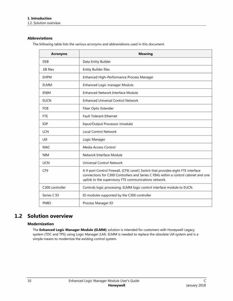
Abbreviations
The following table lists the various acronyms and abbreviations used in this document.
Acronyms Meaning
DEB Data Entity Builder
.EB files Entity Builder files
EHPM Enhanced High–Performance Process Manager
ELMM Enhanced Logic manager Module
ENIM Enhanced Network Interface Module
EUCN Enhanced Universal Control Network
FOE Fiber Optic Extender
FTE Fault Tolerant Ethernet
IOP Input/Output Processor (module)
LCN Local Control Network
LM Logic Manager
MAC Media Access Control
NIM Network Interface Module
UCN Universal Control Network
CF9 A 9-port Control Firewall, (CF9) Level1 Switch that provides eight FTE interface
connections for C300 Controllers and Series C FIMs within a control cabinet and one
uplink to the supervisory FTE communications network.
C300 controller Controls logic processing. ELMM logic control interface module to EUCN.
Series C IO IO modules supported by the C300 controller
PMIO Process Manager IO
1.2 Solution overview
Modernization
The Enhanced Logic Manager Module (ELMM) solution is intended for customers with Honeywell Legacy
system (TDC and TPS) using Logic Manager (LM). ELMM is needed to replace the obsolete LM system and is a
simple means to modernize the existing control system.

1. Introduction
1.2. Solution overview
C Enhanced Logic Manager Module User's Guide 11
January 2018 Honeywell
Benefits
Migrating from the obsolete LM platform to an Experion PKS hardware platform with the latest C300 controllers
ensures facilities of better lifecycle support. Additional benefits include:
Replacement of coaxial cables with superior Ethernet, which is much easier to maintain.
C300, ELMM, and IOs are compact sized controllers requiring less space.
Retaining intellectual property in legacy assets by conserving applications running on the TPN.
Retaining peer-to-peer configurations as they are.
Retaining point processing and checkpoints from the legacy module.
The Solution
The solution includes two major components: (1) ELMM and (2) C300 with series C IOs. Honeywell’s ELMM hosts
all LMM functions. The C300 replaces the LM’s IPC 620 controller and uses a proprietary tool to migrate the LM
database and ladder programs to C300 function blocks. The ELMM is connected to the Enhanced Universal
Control Network (UCN over FTE) and Experion technology. You can also migrate the Logic Manager database to
C300 function blocks, conserve TPN graphics and AM applications, and even retain peer access to HPMs. ELMM
communicates with the C300 through the PCDI block configured in the C300.
ELMMENHANCED LOGIC MANAGER
MODULE
C300 AS LOGIC
CONTROLLER
LMMLOGIC MANAGER MODULE
UCN
LCN
BACKPLANE
COMMUNICATION
LMM POINT
PROCESSING
PC WITH MS-LOADER(SAVED AS CHECKPOINT)
NIM ENIM
UCN ON
IE 802.3
RLL(RELAY
LADDER LOGIC)
IPC 620-XX(PROCESSOR)
EUCN
LCN
FTE
PCDI
COMMUNICATION
LMM POINT
PROCESSING
EXPERION SE RVER
UCN
OVER
FTE
C300
CONTROL
MODULES
Figure 1-1: Existing LMM architecture Figure 1-2: ELMM architecture

1. Introduction
1.3. Hardware and software requirements
12 Enhanced Logic Manager Module User's Guide C
Honeywell January 2018
1.3 Hardware and software requirements
Supported software releases
Software Requirement
TPN TPN R685.3 or later.
See the Customer Release Guide CRG-685 for more details.
Firmware ULM 301.13
o ENIM boot firmware: EPNI2_3.0
o ELMM boot and app firmware: ELMM_100.17.0
o CF9 firmware version: Minimum JJ
ELMM firmware file is included in the ULM media. By default, the firmware files for ELMM are
located at:
o For a 64-bit machine: Computer\C:\Program files (x86)\Honeywell\Experion
PKS\Engineering Tools\system\Firmware\EUCN\ELMM.
o For a 32-bit machine: Computer\C:\Program files\Honeywell\Experion
PKS\Engineering Tools\system\Firmware\EUCN\ELMM.
Ctools: R410.1.85.315 (R410 patch)/R430.1-92.0 (R430 patch)/R431.1.31.0 to update the
ELMM firmware.
See Section 7 of Experion Control Hardware and I/O Modules Firmware Upgrade Guide for more
details.
Use Control Firewall Firmware Update Tool to update the Control Firewall firmware.
See Section 7.11 of the HPM_Installation_HP20600_R685 guide to update the Control Firewall
firmware.
Experion R410.1/R430.1
1. Introduction
1.3. Hardware and software requirements
C Enhanced Logic Manager Module User's Guide 13
January 2018 Honeywell
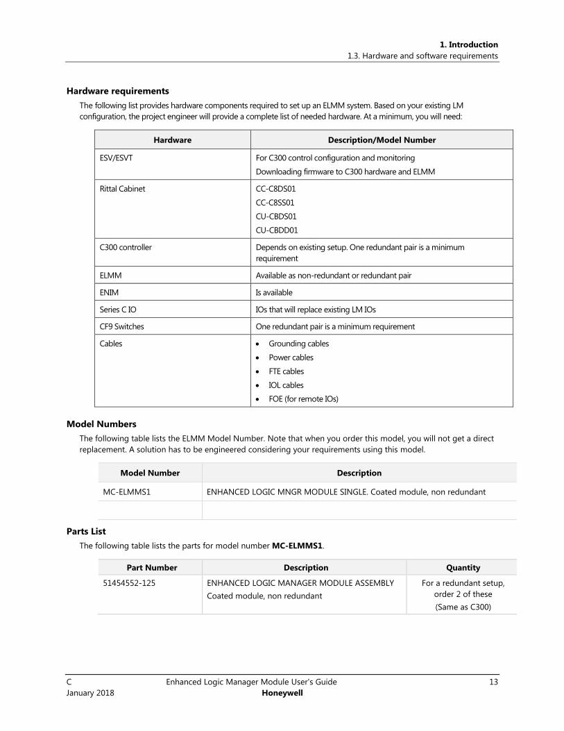
Hardware requirements
The following list provides hardware components required to set up an ELMM system. Based on your existing LM
configuration, the project engineer will provide a complete list of needed hardware. At a minimum, you will need:
Hardware Description/Model Number
ESV/ESVT For C300 control configuration and monitoring
Downloading firmware to C300 hardware and ELMM
Rittal Cabinet CC-C8DS01
CC-C8SS01
CU-CBDS01
CU-CBDD01
C300 controller Depends on existing setup. One redundant pair is a minimum
requirement
ELMM Available as non-redundant or redundant pair
ENIM Is available
Series C IO IOs that will replace existing LM IOs
CF9 Switches One redundant pair is a minimum requirement
Cables Grounding cables
Power cables
FTE cables
IOL cables
FOE (for remote IOs)
Model Numbers
The following table lists the ELMM Model Number. Note that when you order this model, you will not get a direct
replacement. A solution has to be engineered considering your requirements using this model.
Model Number Description
MC-ELMMS1 ENHANCED LOGIC MNGR MODULE SINGLE. Coated module, non redundant
Parts List
The following table lists the parts for model number MC-ELMMS1.
Part Number Description Quantity
51454552-125 ENHANCED LOGIC MANAGER MODULE ASSEMBLY
Coated module, non redundant
For a redundant setup,
order 2 of these
(Same as C300)

C Enhanced Logic Manager Module User's Guide 14
January 2018 Honeywell
2. ELMM Planning and Design
2.1 Planning Considerations Implementing an ELMM solution begins by planning for the following:
Network topology: Understand how ELMM connects to LCN.
EUCN Planning: ELMM connects to EUCN (UCN over FTE). See UCN Planning guide for more details.
Site Selection: Dimensions of existing LM cabinets are marginally different from Series C cabinets that
house ELMMs. Analyze this and work out the location of the new cabinet. Wiring and grounding for the
new cabinet and its hardware components must be planned. ELMM comes factory-fitted in a Series C
cabinet. If your plan is to use an existing UCN cabinet to house the ELMMs, estimate for activities for
mounting ELMM hardware and its components and wiring them.
ELMM and C300 controllers: The number of modules needed based on your requirements, or based
on the number of LM processors being replaced.
ELMM redundancy: ELMM supports redundancy. Plan the number of controllers and ELMMs required if
you want redundancy, or if the LMs being replaced are redundant.
IOs: C300 communicates with an entirely different set of IOs (Series C IOs) compared to LM. Map the
existing IOs with their Series C IO or PMIO equivalents in the planning stage itself. If equivalent LM IOs
are unavailable, an engineering solution may have to be found. If you have existing remote IOs, connect
them via Series C Fiber Optics Extenders.
Process wiring techniques: Study the wiring and grounding requirements of Series C cabinet, Series C
IOs, and remote IOs, if any.
Unique hardware features:
o ELMMs and C300s require FTE cable to connect with CF9s/IE3000 switches, IOs and Experion
Server. Plan for FTE cabling and routing.
o Experion server/ESVT is used for C300 controller configuration and monitoring.
Software requirements: TPN R685.3 or later, Experion R410 or later. CF9 switch configured with version
JJ or later.
Additional customer responsibilities: In general, you are responsible for preparing your facility as
outlined in this guide and references to other guides provided. In addition:
o Install this equipment in accordance with applicable statutory requirements such as National
Electrical Code (NEC), ANSI/NFPA 70, or the Canadian Electrical Code (CEC), C22.1.
o Furnish and install (at your expense and sole responsibility) all internal building wiring
(including power and signal cables) in accordance applicable standards such as NEC or the
CEC.
o Install any power and signal cables according to the applicable standards such as NEC, CEC,
and other local regulations and requirements.
2.2 Network Planning The existing LM architecture and the ELMM architecture diagrams are provided so you can note the differences.
While the LM connected to the LCN through NIMs over LCN trunk cables, the ELMM connects to the LCN via
ENIMs. ELMMs connect to CF9 Switches over the FTE network. The CF9s then connect to L2 switches to the ENIMs.
In an LM system, LCS is replaced with C300, LMM with ELMM.

2. ELMM Planning and Design
2.2. Network Planning
C Enhanced Logic Manager Module User's Guide 15
January 2018 Honeywell
Figure 2-1: LMM topology diagram

2. ELMM Planning and Design
2.3. Site selection
16 Enhanced Logic Manager Module User's Guide C
Honeywell January 2018
The following schematic helps you understand how ELMM is connected to the LCN.
Figure 2-2: ELMM topology diagram
Similar to LMs, ELMM can work either as a redundant pair or a non-redundant module.
C300 and ELMM modules present in the same cabinet must not be connected to the same pair of CF9s. Follow FTE
recommendations to connect EUCN nodes and C300. See the Fault Tolerant Ethernet Overview and
Implementation Guide and Experion Network Best Practices document for additional information.
2.3 Site selection Site selection is an important factor in planning and preparing for the installation of an ELMM system. Cabinet
dimensions, existing location, accessibility of cabinets, wiring, IO cable lengths, presence of remote IOs, are all key
considerations when making your space assessment.
Space assessment for cabinets
There is a minor variation in the dimensions of the cabinets being replaced. Ensure you have taken adequate care
to house the new cabinet in a safe and accessible location. A good plan would entail making a space assessment
by factoring in the difference in the dimensions of the cabinets being replaced.
See the following table to note the difference in cabinet dimensions.

2. ELMM Planning and Design
2.3. Site selection
C Enhanced Logic Manager Module User's Guide 17
January 2018 Honeywell
LM cabinet dimensions
Width (meters/inches) Depth (meters/inches) Height (meters/inches)
MU-CBSM01
(Single Access Cabinet)
0.8/31.5 0.55/21.75 2.1/81.5
MU-CBDM01
(Dual Access Cabinet)
0.8/31.5 0.8/31.5 2.1/81.5
MU-CBSX01
(Single Access Cabinet)
0.8/31.5 0.5/19.7 2/78.9
MU-CBDX01
(Dual Access Cabinet)
0.8/31.5 0.8/31.5 2/78.9
Series C cabinet dimensions
CC-C8SS01
(Single Access Cabinet)
0.8/31.5 0.505/19.89 2.002/78.8
CC-C8DS01
(Dual Access Cabinet)
0.8/31.5 0.8/31.5 2.002/78.8
Follow the guidelines mandated at your site for replacing the LM cabinet with the new Series C cabinet. In
addition, bear in mind the following:
Each cabinet can accommodate a maximum of nearly 25 Series C IOs. The remaining space is taken up by the
redundant C300s and redundant/non-redundant ELMMs. Based on your requirement, you will have to plan for the
additional IOs that you may not be able to accommodate on the same cabinet.
In addition, Wiring, grounding, cable entry to the cabinet have to be assessed to ensure cabinets are placed in a
safe and accessible location. Depending on the location of the new cabinet, plan how to route IO cables to the
new cabinet.
Sample IO configuration
Series C IOs replace all existing LM IOs. As they differ in form, number of available channels, and in the way they
are mounted in the cabinet, assess the number of Series C IOs you will require.
An example is shown here to demonstrate the calculations you will have to make to house the Series C IO
modules that replace the LM IOMs.

2. ELMM Planning and Design
2.4. ELMM/C300 Controllers
18 Enhanced Logic Manager Module User's Guide C
Honeywell January 2018
LM Hardware ELMM Hardware
Primary LM ELMM + redundant C300 pair
Secondary LM Redundant ELMM
4 IO racks = 44 IO modules
Each IO module can have 8,16,24 or 32
channels
Each Series C IO has 32 channels
Assuming all IO modules have 8 channels You will need 11 Series C IOs
Assuming all IO modules have 16 channels You will need 22 Series C IOs
Assuming all IO modules have 32 channels You will need 44 Series C IOs
Each cabinet can accommodate a maximum of nearly 25 Series C IOs. The remaining space is taken up by the
redundant C300s and redundant/non-redundant ELMMs. Based on your requirement, you will have to plan for the
additional IOs that you may not be able to accommodate on the same cabinet.
Remote IOs connect to Series C IO modules within the cabinet via Fiber Optic Extenders (FoE). Installing remote
IOs involves calculating the length of these cables and routing them.
Prepare a plan to identify and reuse cables salvaged from the LM cabinet that you may want to reuse.
2.4 ELMM/C300 Controllers ELMM, the C300 based hardware module, hosts the LMM functions and replaces the LM system. ELMM has the
same form factor as the C300 controller and is designed to retain point processing and checkpoints of LMM.
Redundancy is supported.
The C300 Controller is a distributed process controller and I/O gateway for the Experion system. With only a few
exceptions, the C300 Controller fully supports configuration, load and execution of the standard function blocks
supported in previous Experion releases (R210 and later).
A typical ELMM implementation has ELMM modules installed in the Series C cabinet as specified in Series C
Controller Hardware Configuration Rules document (51199352_revx.docx). Each ELMM system consists of:
One ELMM module (redundant or non-redundant) based on your requirement
One redundant or non-redundant C300 module based on your requirement
Other IOMs including remote IOs dictated by your requirements
Building an ELMM system is similar to building a C300 system with the following additions:
1. ELMM module is mounted in the cabinet and uses the C300 IOTA. Being configurable as redundant or
non-redundant, the ELMM module needs FTE cables to connect to CF9s.
2. You have an option to add an additional pair of CF9s (in addition to what came in the C300 cabinet) to
connect the ELMM node.
3. ELMM uses C300 IOTA. Space for C300 IOTAs to mount ELMM modules is provided in the cabinet.
ELMM can be ordered as either a redundant pair or a non-redundant standalone module to suit your requirement.
Similar to C300, a redundant ELMM also consists of two ELMM modules.
See the Control Hardware Planning Guide EPDOC-XX23-en-431, and C300 Controller Users Guide EPDOC-XX11-en-
431 for information related to planning ELMM/C300 controller planning and design.
C Enhanced Logic Manager Module User's Guide 19
January 2018 Honeywell
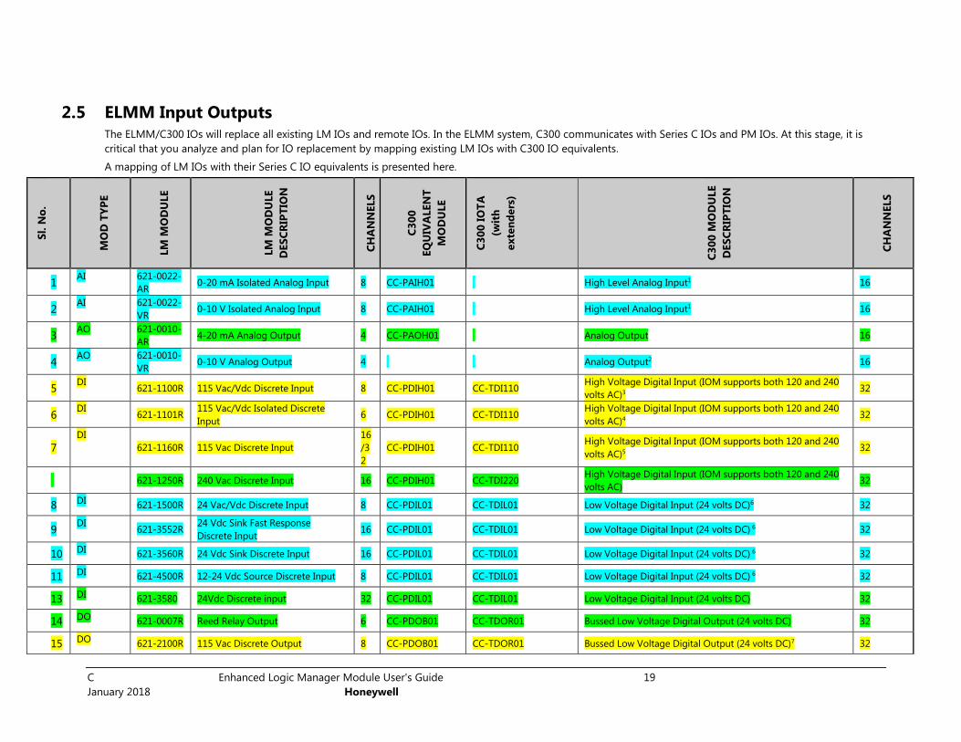
2.5 ELMM Input Outputs The ELMM/C300 IOs will replace all existing LM IOs and remote IOs. In the ELMM system, C300 communicates with Series C IOs and PM IOs. At this stage, it is
critical that you analyze and plan for IO replacement by mapping existing LM IOs with C300 IO equivalents.
A mapping of LM IOs with their Series C IO equivalents is presented here.
Sl. N
o.
MO
D T
YP
E
LM
MO
DU
LE
LM
MO
DU
LE
DES
CR
IPT
ION
CH
AN
NELS
C3
00
EQ
UIV
ALEN
T
MO
DU
LE
C3
00
IO
TA
(wit
h
exte
nd
ers
)
C3
00
MO
DU
LE
DES
CR
IPT
ION
CH
AN
NELS
1 AI 621-0022-
AR 0-20 mA Isolated Analog Input 8 CC-PAIH01 High Level Analog Input1 16
2 AI 621-0022-
VR 0-10 V Isolated Analog Input 8 CC-PAIH01 High Level Analog Input1 16
3 AO 621-0010-
AR 4-20 mA Analog Output 4 CC-PAOH01 Analog Output 16
4 AO 621-0010-
VR 0-10 V Analog Output 4 Analog Output2 16
5 DI
621-1100R 115 Vac/Vdc Discrete Input 8 CC-PDIH01 CC-TDI110 High Voltage Digital Input (IOM supports both 120 and 240
volts AC)3 32
6 DI
621-1101R 115 Vac/Vdc Isolated Discrete
Input 6 CC-PDIH01 CC-TDI110
High Voltage Digital Input (IOM supports both 120 and 240
volts AC)4 32
7
DI
621-1160R 115 Vac Discrete Input
16
/3
2
CC-PDIH01 CC-TDI110 High Voltage Digital Input (IOM supports both 120 and 240
volts AC)5 32
621-1250R 240 Vac Discrete Input 16 CC-PDIH01 CC-TDI220 High Voltage Digital Input (IOM supports both 120 and 240
volts AC) 32
8 DI 621-1500R 24 Vac/Vdc Discrete Input 8 CC-PDIL01 CC-TDIL01 Low Voltage Digital Input (24 volts DC)6 32
9 DI
621-3552R 24 Vdc Sink Fast Response
Discrete Input 16 CC-PDIL01 CC-TDIL01 Low Voltage Digital Input (24 volts DC) 6 32
10 DI 621-3560R 24 Vdc Sink Discrete Input 16 CC-PDIL01 CC-TDIL01 Low Voltage Digital Input (24 volts DC) 6 32
11 DI 621-4500R 12-24 Vdc Source Discrete Input 8 CC-PDIL01 CC-TDIL01 Low Voltage Digital Input (24 volts DC) 6 32
13 DI 621-3580 24Vdc Discrete input 32 CC-PDIL01 CC-TDIL01 Low Voltage Digital Input (24 volts DC) 32
14 DO 621-0007R Reed Relay Output 6 CC-PDOB01 CC-TDOR01 Bussed Low Voltage Digital Output (24 volts DC) 32
15 DO 621-2100R 115 Vac Discrete Output 8 CC-PDOB01 CC-TDOR01 Bussed Low Voltage Digital Output (24 volts DC)7 32
2. ELMM Planning and Design
2.5. ELMM Input Outputs
20 Enhanced Logic Manager Module User's Guide C
Honeywell January 2018
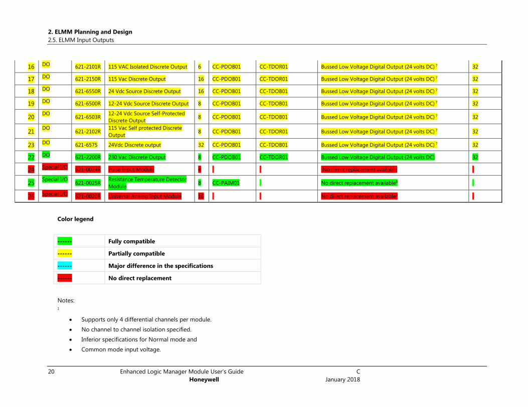
16 DO 621-2101R 115 VAC Isolated Discrete Output 6 CC-PDOB01 CC-TDOR01 Bussed Low Voltage Digital Output (24 volts DC) 7 32
17 DO 621-2150R 115 Vac Discrete Output 16 CC-PDOB01 CC-TDOR01 Bussed Low Voltage Digital Output (24 volts DC) 7 32
18 DO 621-6550R 24 Vdc Source Discrete Output 16 CC-PDOB01 CC-TDOB01 Bussed Low Voltage Digital Output (24 volts DC) 7 32
19 DO 621-6500R 12-24 Vdc Source Discrete Output 8 CC-PDOB01 CC-TDOB01 Bussed Low Voltage Digital Output (24 volts DC) 7 32
20 DO
621-6503R 12-24 Vdc Source Self-Protected
Discrete Output 8 CC-PDOB01 CC-TDOB01 Bussed Low Voltage Digital Output (24 volts DC) 7 32
21 DO
621-2102R 115 Vac Self protected Discrete
Output 8 CC-PDOB01 CC-TDOR01 Bussed Low Voltage Digital Output (24 volts DC) 7 32
23 DO 621-6575 24Vdc Discrete output 32 CC-PDOB01 CC-TDOB01 Bussed Low Voltage Digital Output (24 volts DC) 7 32
22 DO 621-2200R 230 Vac Discrete Output 8 CC-PDOB01 CC-TDOR01 Bussed Low Voltage Digital Output (24 volts DC) 32
24 Special I/O 621-0024R Pulse Input Module 4 No direct replacement available
25 Special I/O
621-0025R Resistance Temperature Detector
Module 8 CC-PAIM01 No direct replacement available8
26 Special I/O 621-0020R Universal Analog Input Module 16 No direct replacement available8
Color legend
------ Fully compatible
------ Partially compatible
------ Major difference in the specifications
------ No direct replacement
Notes:
1
Supports only 4 differential channels per module.
No channel to channel isolation specified.
Inferior specifications for Normal mode and
Common mode input voltage.

2. ELMM Planning and Design
2.5. ELMM Input Outputs
C Enhanced Logic Manager Module User's Guide 21
January 2018 Honeywell
Does not support 0-10V, 0-20mA and Bipolar inputs
2
CC-PAOH01 does not support Voltage output
3
Off state leakage current specification is less. May require external resistor to drain extra leakage current.
4No channel to channel isolation
5
Fusible resistor inputs not available
Input to Logic isolation is only upto 1500V AC/DC"
6
AC Input not supported.
Input delay is 5 ms which is two times the existing specification."
7
"Relay output instead of solid state output.
No Fusible resistor / Fuse protection at the outputs.
No Self protection"
8
No direct replacement available
ATTENTION: LM IO modules that do not have a C300 equivalent module are not supported. An alternative engineering solution is recommended.

C Enhanced Logic Manager Module User's Guide 22
January 2018 Honeywell
Remote IOs
To replace existing remote IOs, use Fiber Optic Extenders to connect IOLs in the cabinet (Series C or PM IOs) with
IOLs in the remote location. A detailed discussion of Series C I/O Link Fiber Optic Extenders (FOE) is provided in
the Series C IO Users Guide EPDOC-X126-en-431.
See the following guides for planning and design information about Series C IO modules:
Control Hardware Planning Guide EPDOC-XX23-en-431
Control Hardware Installation Guide EPDOC-XX21-en-431
Series C IO Users Guide EPDOC-X126-en-431
2.6 Process wiring techniques In the planning stage itself, label field wiring with new module and channel identification prior to removal. Some
IO modules have terminal blocks with friction fit connectors. Others have screw terminals. Determine if the field
wiring is of appropriate size and length for the new module connections.
Cabling Considerations for Series C Components
FTE and IOLINK Cabling
See the section, Series C hardware configuration of the Control Hardware Planning Guide for details.
Connecting IOMs and field devices through I/O Termination Assemblies
See the section, Series C hardware configuration of the Control Hardware Planning Guide for details.
Grounding and power considerations - IOTA boards
See the section, Series C hardware configuration of the Control Hardware Planning Guide for details.
Grounding requirements
See the section, ‘Series C hardware configuration’ of the Control Hardware Planning Guide for details.
Power entry guidelines for Series C cabinet
See the section, ‘Selecting power entry accessories’ from the Control Hardware Planning Guide EPDOC-XX23-en-
431 document for details on how to supply AC line power wiring through Standard Power Entry or Optional Power
Entry to the Series C cabinet power supplies and fan assemblies.
See the section, ‘Install ELMM’, and follow additional guidelines provided to ensure you have made adequate
preparations for installing the new Series C cabinet.
All details related to precautions, recommendations, and wiring procedures are provided in the following user
guides:
Control Hardware Planning Guide EPDOC-XX23-en-431
Control Hardware Installation Guide EPDOC-XX21-en-431
C300 Controller Users Guide EPDOC-XX11-en-431
Series C IO Users Guide EPDOC-X126-en-431
2.7 Unique hardware features For information related to setting up FTE infrastructure for the ELMM system, see the following guides:
Fault Tolerant Ethernet Overview and Implementation Guide EPDOC-XX37-en-431
Control Hardware Planning Guide EPDOC-XX23-en-431
Control Hardware Installation Guide EPDOC-XX21-en-431
C300 Controller Users Guide EPDOC-XX11-en-431

2. ELMM Planning and Design
2.7. Unique hardware features
C Enhanced Logic Manager Module User's Guide 23
January 2018 Honeywell
Series C IO Users Guide EPDOC-X126-en-431

C Enhanced Logic Manager Module User's Guide 24
January 2018 Honeywell
3. ELMM Installation
3.1 Overview
Disassemble and remove LM
Before ELMM installation can begin, you must disassemble existing LM equipment and safely transport it away from the
site. Exercise caution to power down equipment – cabinet, card files, IOs, remote IO racks - and follow all instructions
provided in this guide and the guides referenced herein when uninstalling LM equipment.
Label field wiring with new module and channel identification prior to removal. Some IO modules have terminal
blocks with friction fit connectors. Others have screw terminals. Determine if the field wiring is of appropriate size
and length for the new module connections.
Install ELMM
The hardware required to replace your existing LM with ELMM is factory built and shipped. Ensure proper cabling is done
by trained technicians using appropriate equipment.
Based on your requirements, Honeywell’s project engineer calculates the number of ELMM modules, C300s, CF9 switches,
L2 switches, and IOs (mapped to equivalent IPC IO modules being replaced) required to replace your existing LM system.
After gathering your requirement, the engineer designs a solution consisting of the appropriate hardware modules
required and feeds the same to the TPC tool. This tool then generates a BOM which Honeywell uses to build the required
ELMM solution.
You will receive a cabinet fitted with all the hardware. Install the cabinet at the planned location. Ensure proper cabling
supplies rated power to the cabinet and equipment. Connect IOs and remote IO to the C300 controller as per plan.
3.2 LM Shutdown and Hardware Disassembly After a plan to replace LM with ELMM is in place, begin to shutdown and disassemble LM hardware. The sequence
of steps to power down and disassemble LM hardware is provided here.
Step Action
1 Prepare the LM for shutdown. Record the existing UCN and UCN Network address information in
the EUCN Configuration Data Checklist entries for NIMs.
2 Checkpoint LMs.
3 Record the switch settings of the existing LM for future reference.
4 Generate ladder logic files.
5 Generate UCN & Node specific EB files.
6 Shutdown LM from Native Window.
7 Power down LM hardware and remove wiring.
8 Remove card files and modules from the cabinet.
9 Remove the cabinet.
3.3 Preparing the LM for shutdown Ensure the following checklist items are completed to prepare the LM for shutdown.

3. ELMM Installation
3.3. Preparing the LM for shutdown
C Enhanced Logic Manager Module User's Guide 25
January 2018 Honeywell
Item Reference
Record the existing UCN and UCN Network address
information for NIMs in the EUCN Configuration Data
Checklist attached to this document.
Checkpoint and take a backup of LM checkpoint files. See
Section 21 of Engineer’s Reference Manual
SW09-605
Checkpoint LM in this document for more
details.
Checkpoint all LMs on the UCN and shut them down before
shutting down the NIMs.
See Section 21 of Engineer’s Reference
Manual SW09-605
Record DIP switch settings on the existing LMs for future
reference.
Record the DIP switch settings on the Serial IO Module.
Generate and save Ladder logic files.
Generate and save UCN and Node specific EB files.
Checkpoint LM
Data checkpointing is performed to maintain up-to-date device settings in the event a device is taken out of
service. Prior to replacing LM with ELMM, checkpoint NIM and LM to save existing data.
The following diagram gives a snapshot of the checkpointing process.

3. ELMM Installation
3.4. Shut down LM
26 Enhanced Logic Manager Module User's Guide C
Honeywell January 2018
Figure 3-1: Overview of the checkpointing process
See Section 21 of the Engineer’s Reference Manual for more details.
Record Current LM Card File Configuration
It is important you record the switch settings of the existing LM for future reference. Ensure you complete this
activity before disassembling the LM hardware.
See chapter 2 of the LM Service manual LM13500 for information about switch settings on the LM card file.
Generate Ladder Logic files
Generate and save the following files before shutting down the LM.
PRN file
Label File
Force List
See the Data Entity Builder Manual SW11-611 and the 620 WinLoader, Version 5.4, User Manual for additional
information.
Generate UCN & Node specific EB files
See the Data Entity Builder Manual SW11-611 for additional information about Print entities.
See Appendix D (for Exception Building) and Appendix E (for Creating Exception Build Files from IDFs) of the
System-startup-guide-cd-rom-sw11600 document.
3.4 Shut down LM After checkpointing LMs and backing up ladder logic and EB files, proceed to shutdown LMs and disassemble the
LM hardware and remove the cabinet. This section details procedures to shut down the LM system and remove
the hardware and cabinet.
The following tasks must be performed in the given order for a safe and successful shutdown of LM hardware.
Step Action
1 In case of a redundant LM processor, shutdown the backup LM processor from Native Window.
2 Shutdown primary LM processor from Native Window.
3 It is recommended you isolate power to IOs in the bottom-up order i.e., remove power to the IO
card file at the bottom first, followed by the one above it and so on.
4 Isolate power to the secondary LM processor card file by disconnecting power cord from power
source.
5 Isolate power to the primary LM processor card file by disconnecting power cord from power
source.
6 Record switch settings of primary and secondary LM processor cards.
7 Record switch settings of SIOM/PLDM cards.
8 Isolate power to remote IOs and record switch settings of SIOM.

3. ELMM Installation
3.5. Shut down LM from Native Window
C Enhanced Logic Manager Module User's Guide 27
January 2018 Honeywell
3.5 Shut down LM from Native Window From an R6xx LCN station – for instance, US, GUS, ES-T, or PCUS, perform the following procedure to shut down
the R6xx LM. For information about Displays see the Logic Manager Service LM13-685 manual.
Step Action
1 Depress the <SYST STAT> (System Status) key on the system console to invoke the System Status
display.
2 Choose the NIM node in the display grid that the LM is resident on and then select the NTWK/HWY
STATUS target to invoke the UCN Status display.
3 Choose the LM of interest on the display grid and then select the DETAIL STATUS target on the
UCN Status display.
For redundant nodes, perform steps 4 and 5. For a non redundant node, skip to step 6.
4 Choose the secondary LM (Status shows BACKUP) and then select RUN STATES target.
5 Choose the SHUTDOWN target and execute the command by selecting the ENTER target. The
secondary LM enters the ALIVE state.
6 Choose the primary LM (Status shows OK) and then select RUN STATES target.
7 Choose the IDLE target and execute the command by selecting the ENTER target. The LM enters the
IDLE state.
8 Choose the SHUTDOWN target and execute the command by selecting the ENTER target. The LM
enters the ALIVE state.
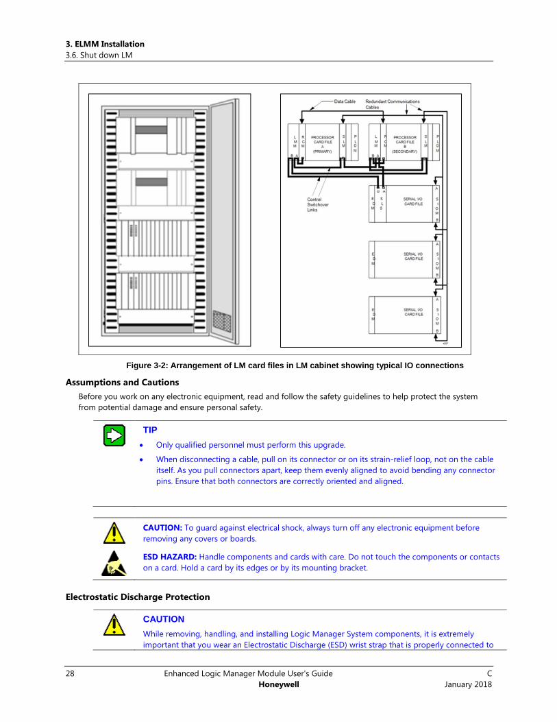
3.6 Shut down LM You can now proceed to shutdown the LM by isolating power to the LM hardware and cabinet.
Typically, the Logic Manager card files are installed in the single or dual access cabinets as depicted in the
following diagram. The redundant IPC 620 processors sit at the top of the cabinet followed by the Serial IO card
files underneath. Follow a bottom-up approach when isolating power to the LM system. Power is isolated to the
bottom most IO card file followed by the one above it and so on. When isolating power to the IPC 620 processors,
shut down the secondary processor before the primary. If remote IO racks are present, isolate power and remove
the Serial Link cable.
3. ELMM Installation
3.6. Shut down LM
28 Enhanced Logic Manager Module User's Guide C
Honeywell January 2018
Figure 3-2: Arrangement of LM card files in LM cabinet showing typical IO connections
Assumptions and Cautions
Before you work on any electronic equipment, read and follow the safety guidelines to help protect the system
from potential damage and ensure personal safety.
TIP
Only qualified personnel must perform this upgrade.
When disconnecting a cable, pull on its connector or on its strain-relief loop, not on the cable
itself. As you pull connectors apart, keep them evenly aligned to avoid bending any connector
pins. Ensure that both connectors are correctly oriented and aligned.
CAUTION: To guard against electrical shock, always turn off any electronic equipment before
removing any covers or boards.
ESD HAZARD: Handle components and cards with care. Do not touch the components or contacts
on a card. Hold a card by its edges or by its mounting bracket.
Electrostatic Discharge Protection
CAUTION
While removing, handling, and installing Logic Manager System components, it is extremely
important that you wear an Electrostatic Discharge (ESD) wrist strap that is properly connected to

3. ELMM Installation
3.6. Shut down LM
C Enhanced Logic Manager Module User's Guide 29
January 2018 Honeywell
ground. Be sure power to the equipment is off. Slip the strap on your wrist like a wristwatch and
connect its clip to the ground bus located inside the front, left side of the cabinet.
Wearing an approved ESD wrist strap does not increase the danger of electrical shock.
ESD Wrist strap Connection in the Logic Manager Cabinet
Be sure to store any electronic component in a static-safe carrying pouch whenever it is not in use.

3. ELMM Installation
3.7. Remove LM hardware
30 Enhanced Logic Manager Module User's Guide C
Honeywell January 2018
An ESD kit is available through Honeywell. Contact your Honeywell representative and ask for part
number 30185-H.
3.7 Remove LM hardware LM hardware removal can proceed in one of two ways.
1. Disassemble IO files from each IO card file and then remove the card files.
2. Remove the card files directly.
If you plan to reuse cables, tag them and safely store them so they can be identified.

3. ELMM Installation
3.7. Remove LM hardware
C Enhanced Logic Manager Module User's Guide 31
January 2018 Honeywell
Identify Components for Disassembly
Logic Manager Processor Card File
Logic Manager Redundant Processor Card File
I/O Card Files
Remote IO racks
Power cables
IO cables
UCN cables
UCN taps
Disassembly Procedure
Use the following procedure to disassemble the LM hardware.
Step Action
1 Shut down power supply to the LM processor, LM redundant processor, and all IO racks (local and
remote).
TIP: Make sure no LED is lit up in any of the racks signifying power has been isolated from the racks.
2 Disconnect the power cables to remove power from the LM Processor card file, LM Redundant
Processor card file, and I/O Card Files.
3. ELMM Installation
3.7. Remove LM hardware
32 Enhanced Logic Manager Module User's Guide C
Honeywell January 2018
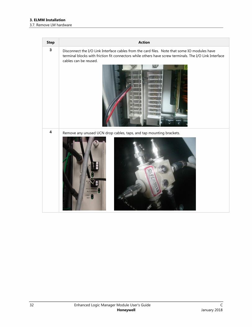
Step Action
3 Disconnect the I/O Link Interface cables from the card files. Note that some IO modules have
terminal blocks with friction fit connectors while others have screw terminals. The I/O Link Interface
cables can be reused.
4 Remove any unused UCN drop cables, taps, and tap mounting brackets.

3. ELMM Installation
3.8. Remove Module
C Enhanced Logic Manager Module User's Guide 33
January 2018 Honeywell
Step Action
5 Loosen, but do not remove the four screws holding the card file to its support.
6 Grasp the card file firmly and lift it about 1 cm (1/2 in.) to release the file into your hands.
7 If you have remote IO racks, isolate power and remove the Serial Link cable.
3.8 Remove Module
Use the following procedure to remove the Logic Manager System module.
Step Action
1 Remove power from the Logic Manager processor card file by placing the power breakers in the off
position.
WARNING: Do not use the power supply module fuse as a means of disconnecting power from the
card file. Each card file must have its own individual circuit breaker for this purpose.
2 Before removing a Logic Manager System module, connect your ESD wrist strap to the cabinet
ground bar, or if the equipment is panel mounted, connect your ESD wrist strap to the panel
ground.
3. ELMM Installation
3.8. Remove Module
34 Enhanced Logic Manager Module User's Guide C
Honeywell January 2018
Step Action
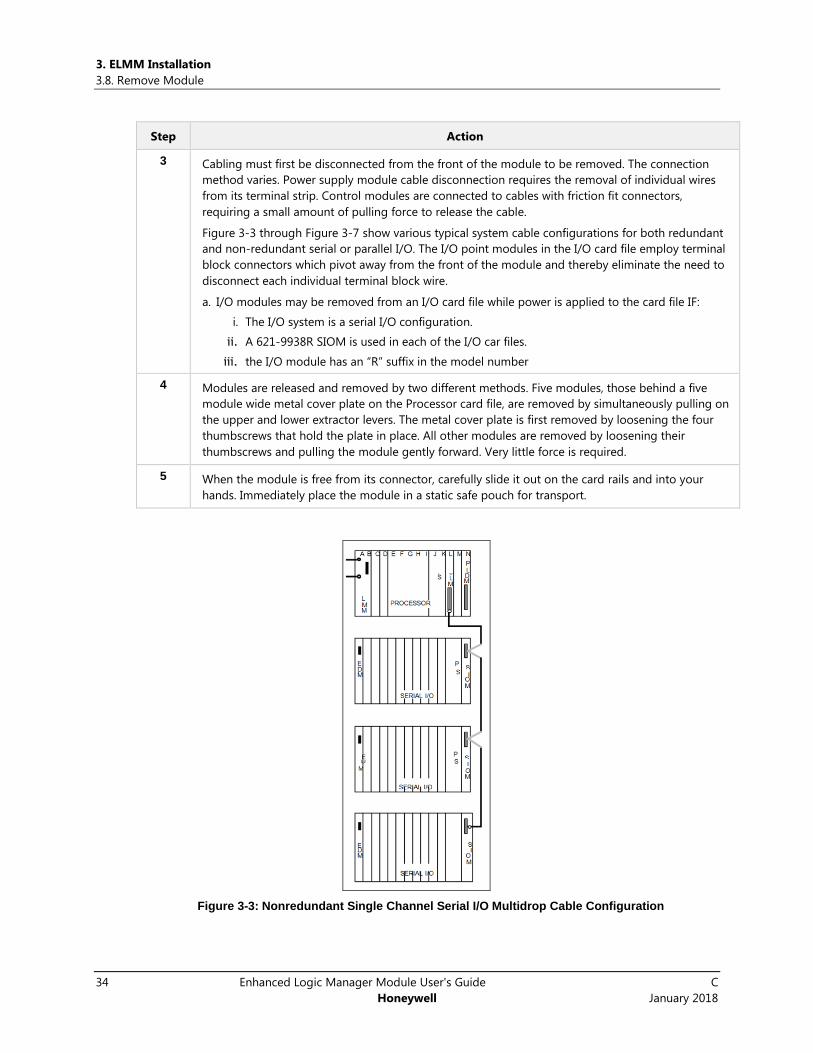
3 Cabling must first be disconnected from the front of the module to be removed. The connection
method varies. Power supply module cable disconnection requires the removal of individual wires
from its terminal strip. Control modules are connected to cables with friction fit connectors,
requiring a small amount of pulling force to release the cable.
Figure 3-3 through Figure 3-7 show various typical system cable configurations for both redundant
and non-redundant serial or parallel I/O. The I/O point modules in the I/O card file employ terminal
block connectors which pivot away from the front of the module and thereby eliminate the need to
disconnect each individual terminal block wire.
a. I/O modules may be removed from an I/O card file while power is applied to the card file IF:
i. The I/O system is a serial I/O configuration.
ii. A 621-9938R SIOM is used in each of the I/O car files.
iii. the I/O module has an “R” suffix in the model number
4 Modules are released and removed by two different methods. Five modules, those behind a five
module wide metal cover plate on the Processor card file, are removed by simultaneously pulling on
the upper and lower extractor levers. The metal cover plate is first removed by loosening the four
thumbscrews that hold the plate in place. All other modules are removed by loosening their
thumbscrews and pulling the module gently forward. Very little force is required.
5 When the module is free from its connector, carefully slide it out on the card rails and into your
hands. Immediately place the module in a static safe pouch for transport.
Figure 3-3: Nonredundant Single Channel Serial I/O Multidrop Cable Configuration

3. ELMM Installation
3.8. Remove Module
C Enhanced Logic Manager Module User's Guide 35
January 2018 Honeywell
Figure 3-4: Nonredundant Four Channel Serial I/O Multidrop Cable Configuration
Figure 3-5: Nonredundant Parallel I/O Cable Configuration

3. ELMM Installation
3.8. Remove Module
36 Enhanced Logic Manager Module User's Guide C
Honeywell January 2018
Figure 3-6: Redundant Serial I/O Cable Configuration
Figure 3-7: Redundant Parallel I/O Cable Configuration
3. ELMM Installation
3.9. Remove Card File
C Enhanced Logic Manager Module User's Guide 37
January 2018 Honeywell
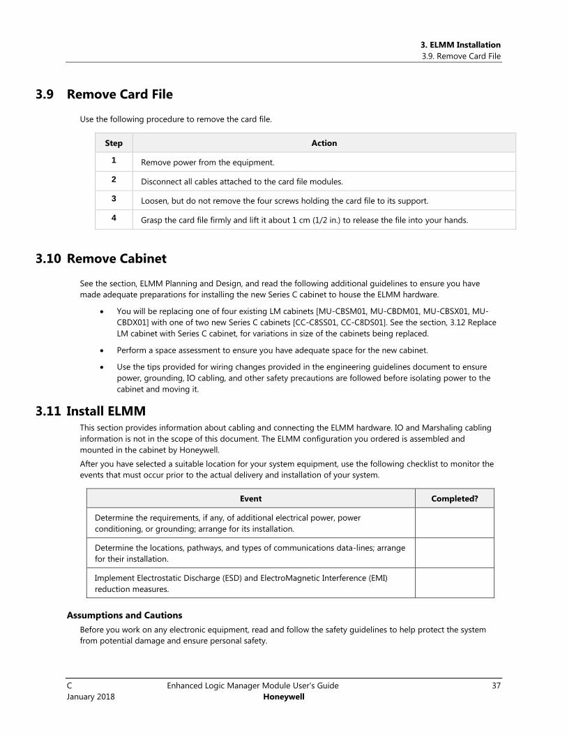
3.9 Remove Card File
Use the following procedure to remove the card file.
Step Action
1 Remove power from the equipment.
2 Disconnect all cables attached to the card file modules.
3 Loosen, but do not remove the four screws holding the card file to its support.
4 Grasp the card file firmly and lift it about 1 cm (1/2 in.) to release the file into your hands.
3.10 Remove Cabinet
See the section, ELMM Planning and Design, and read the following additional guidelines to ensure you have
made adequate preparations for installing the new Series C cabinet to house the ELMM hardware.
You will be replacing one of four existing LM cabinets [MU-CBSM01, MU-CBDM01, MU-CBSX01, MU-
CBDX01] with one of two new Series C cabinets [CC-C8SS01, CC-C8DS01]. See the section, 3.12 Replace
LM cabinet with Series C cabinet, for variations in size of the cabinets being replaced.
Perform a space assessment to ensure you have adequate space for the new cabinet.
Use the tips provided for wiring changes provided in the engineering guidelines document to ensure
power, grounding, IO cabling, and other safety precautions are followed before isolating power to the
cabinet and moving it.
3.11 Install ELMM This section provides information about cabling and connecting the ELMM hardware. IO and Marshaling cabling
information is not in the scope of this document. The ELMM configuration you ordered is assembled and
mounted in the cabinet by Honeywell.
After you have selected a suitable location for your system equipment, use the following checklist to monitor the
events that must occur prior to the actual delivery and installation of your system.
Event Completed?
Determine the requirements, if any, of additional electrical power, power
conditioning, or grounding; arrange for its installation.
Determine the locations, pathways, and types of communications data-lines; arrange
for their installation.
Implement Electrostatic Discharge (ESD) and ElectroMagnetic Interference (EMI)
reduction measures.
Assumptions and Cautions
Before you work on any electronic equipment, read and follow the safety guidelines to help protect the system
from potential damage and ensure personal safety.

3. ELMM Installation
3.11. Install ELMM
38 Enhanced Logic Manager Module User's Guide C
Honeywell January 2018
TIP
Only qualified personnel with working knowledge of C300 controllers must perform this
upgrade.
When disconnecting a cable, pull on its connector or on its strain-relief loop, not on the cable
itself. As you pull connectors apart, keep them evenly aligned to avoid bending any connector
pins. Ensure that both connectors are correctly oriented and aligned.
CAUTION: To guard against electrical shock, always turn off any electronic equipment before
removing any covers or boards.
ESD HAZARD: Handle components and cards with care. Do not touch the components or contacts
on a card. Hold a card by its edges or by its mounting bracket.
Installation Tools
See the C300 Controller Users Guide EPDOC-XX11-en-431A and Control Hardware Planning Guide EPDOC-XX23-
en-431for a list of tools you will need to install hardware.
Overview of Tasks
Based on your requirement, the Series C cabinet factory-fitted with ELMMs and IO modules will be delivered.
However, if you choose to install the hardware yourself, the following tasks, in the order prescribed, must be
performed.
Task Go to: Done?
Replace LM cabinet with C300 cabinet Replace LM cabinet with Series C
cabinet (CC-C8DS01, CC-C8SS01)
Install the carrier adapter assembly is in the Series C
cabinet
Control Hardware Planning Guide
EPDOC-XX23-en-431
C300 Controller Users Guide
EPDOC-XX11-en-431
Mount the CF9 IOTAs on the backplane Control Firewall User's Guide
Control Hardware Planning Guide
EPDOC-XX23-en-431
C300 Controller Users Guide
EPDOC-XX11-en-431
Mount the C300 and ELMM IOTAs on the backplane C300 Controller Users Guide
EPDOC-XX11-en-431
Mount the Series C IOTAs on the backplane Series C IO Users Guide EPDOC-
X126-en-431
Control Hardware Planning Guide
EPDOC-XX23-en-431
Mount the backplane on the carrier in the cabinet C300 Controller Users Guide
EPDOC-XX11-en-431
3. ELMM Installation
3.12. Replace LM cabinet with Series C cabinet (CC-C8DS01, CC-C8SS01)
C Enhanced Logic Manager Module User's Guide 39
January 2018 Honeywell
Task Go to: Done?
Mount the CF9 module on the CF9 IOTA Control Firewall User's Guide
Control Hardware Planning Guide
EPDOC-XX23-en-431
Mount the RAM battery backup assembly on the carrier C300 Controller Users Guide
EPDOC-XX11-en-431
Mount the C300 module on the C300 IOTA Control Hardware Planning Guide
EPDOC-XX23-en-431
Mount the Series C IO on the Series C IOTA Series C IO Users Guide EPDOC-
X126-en-431
C300 Controller Users Guide
EPDOC-XX11-en-431
Series C cabinet Cabling Control Hardware Planning Guide
EPDOC-XX23-en-431
Series C components Cabling Control Hardware Planning Guide
EPDOC-XX23-en-431
Power and Grounding requirements Control Hardware Planning Guide
EPDOC-XX23-en-431
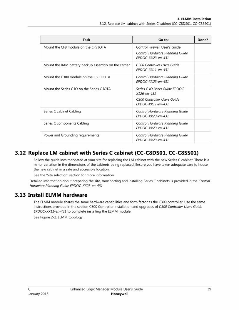
3.12 Replace LM cabinet with Series C cabinet (CC-C8DS01, CC-C8SS01) Follow the guidelines mandated at your site for replacing the LM cabinet with the new Series C cabinet. There is a
minor variation in the dimensions of the cabinets being replaced. Ensure you have taken adequate care to house
the new cabinet in a safe and accessible location.
See the ‘Site selection’ section for more information.
Detailed information about preparing the site, transporting and installing Series C cabinets is provided in the Control
Hardware Planning Guide EPDOC-XX23-en-431.
3.13 Install ELMM hardware The ELMM module shares the same hardware capabilities and form factor as the C300 controller. Use the same
instructions provided in the section C300 Controller installation and upgrades of C300 Controller Users Guide
EPDOC-XX11-en-431 to complete installing the ELMM module.
See Figure 2-2: ELMM topology
3. ELMM Installation
3.14. Provide strain-relief to FTE cables
40 Enhanced Logic Manager Module User's Guide C
Honeywell January 2018
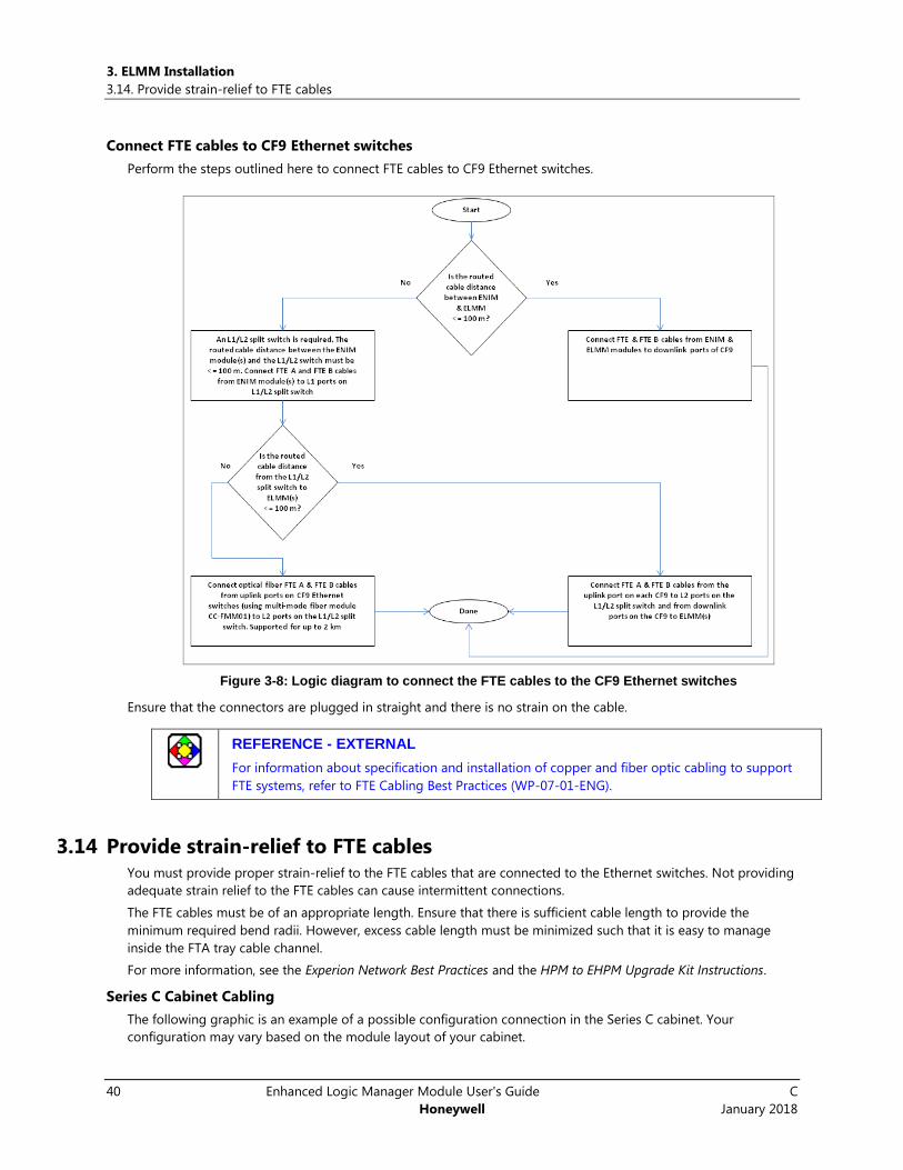
Connect FTE cables to CF9 Ethernet switches
Perform the steps outlined here to connect FTE cables to CF9 Ethernet switches.
Figure 3-8: Logic diagram to connect the FTE cables to the CF9 Ethernet switches
Ensure that the connectors are plugged in straight and there is no strain on the cable.
REFERENCE - EXTERNAL
For information about specification and installation of copper and fiber optic cabling to support
FTE systems, refer to FTE Cabling Best Practices (WP-07-01-ENG).
3.14 Provide strain-relief to FTE cables You must provide proper strain-relief to the FTE cables that are connected to the Ethernet switches. Not providing
adequate strain relief to the FTE cables can cause intermittent connections.
The FTE cables must be of an appropriate length. Ensure that there is sufficient cable length to provide the
minimum required bend radii. However, excess cable length must be minimized such that it is easy to manage
inside the FTA tray cable channel.
For more information, see the Experion Network Best Practices and the HPM to EHPM Upgrade Kit Instructions.
Series C Cabinet Cabling
The following graphic is an example of a possible configuration connection in the Series C cabinet. Your
configuration may vary based on the module layout of your cabinet.

3. ELMM Installation
3.14. Provide strain-relief to FTE cables
C Enhanced Logic Manager Module User's Guide 41
January 2018 Honeywell
Figure 3-9: Series C cabling
3. ELMM Installation
3.15. Cabling Considerations for Series C Components
42 Enhanced Logic Manager Module User's Guide C
Honeywell January 2018
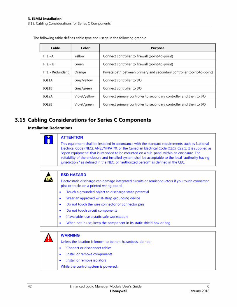
The following table defines cable type and usage in the following graphic.
Cable Color Purpose
FTE –A Yellow Connect controller to firewall (point-to-point)
FTE – B Green Connect controller to firewall (point-to-point)
FTE - Redundant Orange Private path between primary and secondary controller (point-to-point)
IOL1A Grey/yellow Connect controller to I/O
IOL1B Grey/green Connect controller to I/O
IOL2A Violet/yellow Connect primary controller to secondary controller and then to I/O
IOL2B Violet/green Connect primary controller to secondary controller and then to I/O
3.15 Cabling Considerations for Series C Components
Installation Declarations
ATTENTION
This equipment shall be installed in accordance with the standard requirements such as National
Electrical Code (NEC), ANSI/NFPA 70, or the Canadian Electrical Code (CEC), C22.1. It is supplied as
"open equipment" that is intended to be mounted on a sub-panel within an enclosure. The
suitability of the enclosure and installed system shall be acceptable to the local "authority having
jurisdiction," as defined in the NEC, or "authorized person" as defined in the CEC.
ESD HAZARD
Electrostatic discharge can damage integrated circuits or semiconductors if you touch connector
pins or tracks on a printed wiring board.
Touch a grounded object to discharge static potential
Wear an approved wrist-strap grounding device
Do not touch the wire connector or connector pins
Do not touch circuit components
If available, use a static safe workstation
When not in use, keep the component in its static shield box or bag
WARNING
Unless the location is known to be non-hazardous, do not:
Connect or disconnect cables
Install or remove components
Install or remove isolators
While the control system is powered.

3. ELMM Installation
3.16. Grounding requirements
C Enhanced Logic Manager Module User's Guide 43
January 2018 Honeywell
FTE and IOLINK Cabling
See the section Series C hardware configuration of the Control Hardware Planning Guide for details.
Connecting IOMs and field devices through I/O Termination Assemblies
See the section, Series C hardware configuration of the Control Hardware Planning Guide for details.
Grounding and power considerations - IOTA boards
See the section, Series C hardware configuration of the Control Hardware Planning Guide for details.
3.16 Grounding requirements See the section, ‘Series C hardware configuration’ of the Control Hardware Planning Guide for details.
Power entry guidelines for Series C cabinet
See the section, ‘Selecting power entry accessories’ from the Control Hardware Planning Guide EPDOC-XX23-en-
431 document for details on how to supply AC line power wiring through Standard Power Entry or Optional Power
Entry to the Series C cabinet power supplies and fan assemblies.
See the section, ‘Install ELMM’, and follow additional guidelines provided to ensure you have made adequate
preparations for installing the new Series C cabinet.
3.17 EUCN installation This section provides references to documentation available for installing the hardware and software for
completing the EUCN installation.
Hardware
For hardware installation procedures and cabling information, see the following documents.
For information about Refer
Topology Network Planning section of this document.
FTE network and planning Section 8 and 9 of Universal Control Network Planning UN02501 R684
Cabling information Section 2.6 to 2.13 of Universal Control Network Installation UN20500 R684
EUCN Power-On Test Section 5.6 of Universal Control Network Installation UN20500 R684
Ethernet switch installation & configuration Section 16 and 17 of TPN System Installation SW20600
CF9 Switch installation Section 7.10 of HPM Installation HP20600 R685
CF9 uplink cable connection
Use the ninth port on the CF9 to provide an uplink to the supervisory FTE network and level 2 control. Also see Fig 2-2 of
Universal Control Network Installation UN20500 document.
Redundant ELMM considerations
Connect both ELMMs to the same CF9 pair.
Primary ELMM must be configured with an odd number between 1-509. Secondary will be the following even
number.
Note: Third port redundancy is not supported by redundant ELMM modules.
4. ELMM Configuration and Operations
4.1. Pre-configuration checklist
44 Enhanced Logic Manager Module User's Guide C
Honeywell January 2018
4. ELMM Configuration and Operations
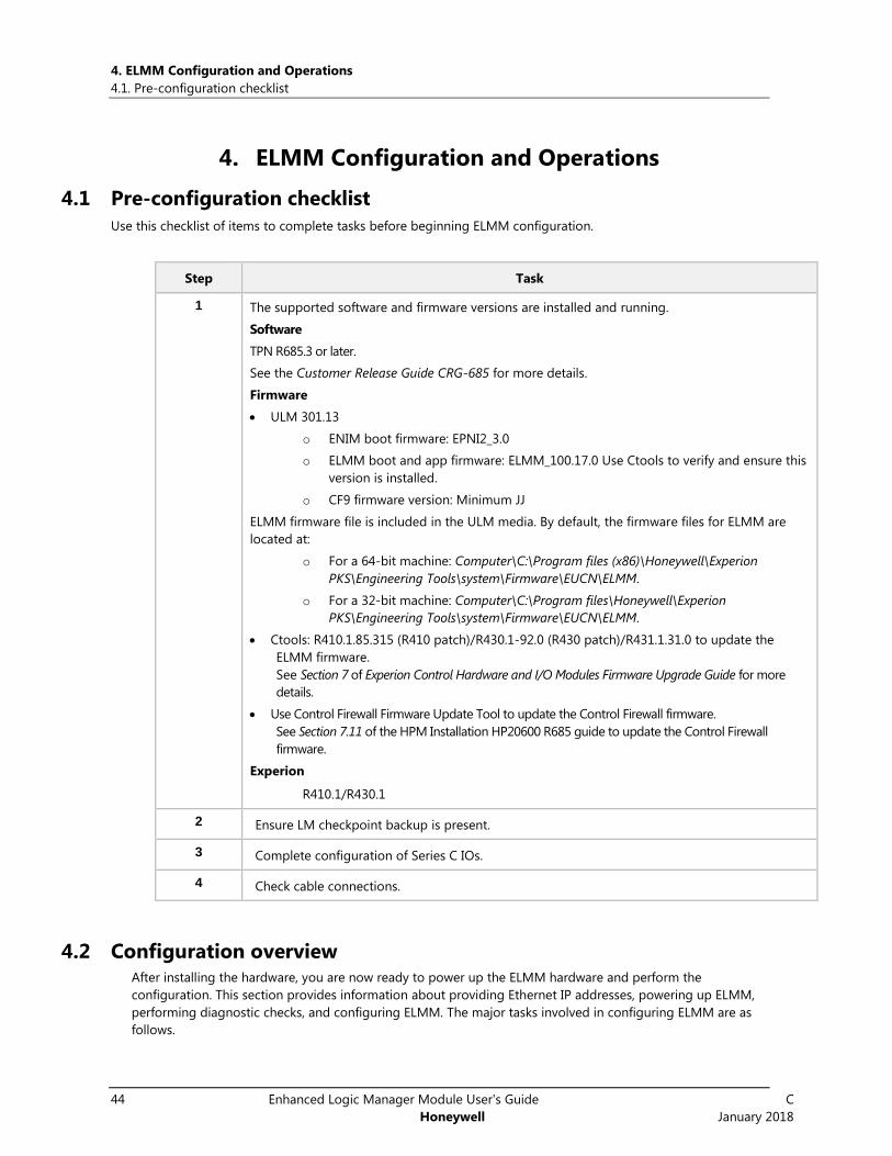
4.1 Pre-configuration checklist
Use this checklist of items to complete tasks before beginning ELMM configuration.
Step Task
1 The supported software and firmware versions are installed and running.
Software
TPN R685.3 or later.
See the Customer Release Guide CRG-685 for more details.
Firmware
ULM 301.13
o ENIM boot firmware: EPNI2_3.0
o ELMM boot and app firmware: ELMM_100.17.0 Use Ctools to verify and ensure this
version is installed.
o CF9 firmware version: Minimum JJ
ELMM firmware file is included in the ULM media. By default, the firmware files for ELMM are
located at:
o For a 64-bit machine: Computer\C:\Program files (x86)\Honeywell\Experion
PKS\Engineering Tools\system\Firmware\EUCN\ELMM.
o For a 32-bit machine: Computer\C:\Program files\Honeywell\Experion
PKS\Engineering Tools\system\Firmware\EUCN\ELMM.
Ctools: R410.1.85.315 (R410 patch)/R430.1-92.0 (R430 patch)/R431.1.31.0 to update the
ELMM firmware.
See Section 7 of Experion Control Hardware and I/O Modules Firmware Upgrade Guide for more
details.
Use Control Firewall Firmware Update Tool to update the Control Firewall firmware.
See Section 7.11 of the HPM Installation HP20600 R685 guide to update the Control Firewall
firmware.
Experion
R410.1/R430.1
2 Ensure LM checkpoint backup is present.
3 Complete configuration of Series C IOs.
4 Check cable connections.
4.2 Configuration overview After installing the hardware, you are now ready to power up the ELMM hardware and perform the
configuration. This section provides information about providing Ethernet IP addresses, powering up ELMM,
performing diagnostic checks, and configuring ELMM. The major tasks involved in configuring ELMM are as
follows.
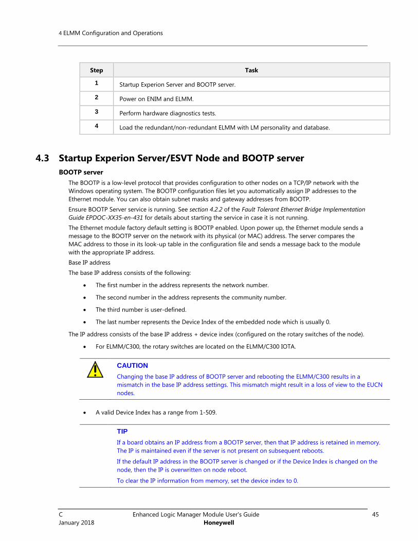
4 ELMM Configuration and Operations
C Enhanced Logic Manager Module User's Guide 45
January 2018 Honeywell
Step Task
1 Startup Experion Server and BOOTP server.
2 Power on ENIM and ELMM.
3 Perform hardware diagnostics tests.
4 Load the redundant/non-redundant ELMM with LM personality and database.
4.3 Startup Experion Server/ESVT Node and BOOTP server
BOOTP server
The BOOTP is a low-level protocol that provides configuration to other nodes on a TCP/IP network with the
Windows operating system. The BOOTP configuration files let you automatically assign IP addresses to the
Ethernet module. You can also obtain subnet masks and gateway addresses from BOOTP.
Ensure BOOTP Server service is running. See section 4.2.2 of the Fault Tolerant Ethernet Bridge Implementation
Guide EPDOC-XX35-en-431 for details about starting the service in case it is not running.
The Ethernet module factory default setting is BOOTP enabled. Upon power up, the Ethernet module sends a
message to the BOOTP server on the network with its physical (or MAC) address. The server compares the
MAC address to those in its look-up table in the configuration file and sends a message back to the module
with the appropriate IP address.
Base IP address
The base IP address consists of the following:
The first number in the address represents the network number.
The second number in the address represents the community number.
The third number is user-defined.
The last number represents the Device Index of the embedded node which is usually 0.
The IP address consists of the base IP address + device index (configured on the rotary switches of the node).
For ELMM/C300, the rotary switches are located on the ELMM/C300 IOTA.
CAUTION
Changing the base IP address of BOOTP server and rebooting the ELMM/C300 results in a
mismatch in the base IP address settings. This mismatch might result in a loss of view to the EUCN
nodes.
A valid Device Index has a range from 1-509.
TIP
If a board obtains an IP address from a BOOTP server, then that IP address is retained in memory.
The IP is maintained even if the server is not present on subsequent reboots.
If the default IP address in the BOOTP server is changed or if the Device Index is changed on the
node, then the IP is overwritten on node reboot.
To clear the IP information from memory, set the device index to 0.
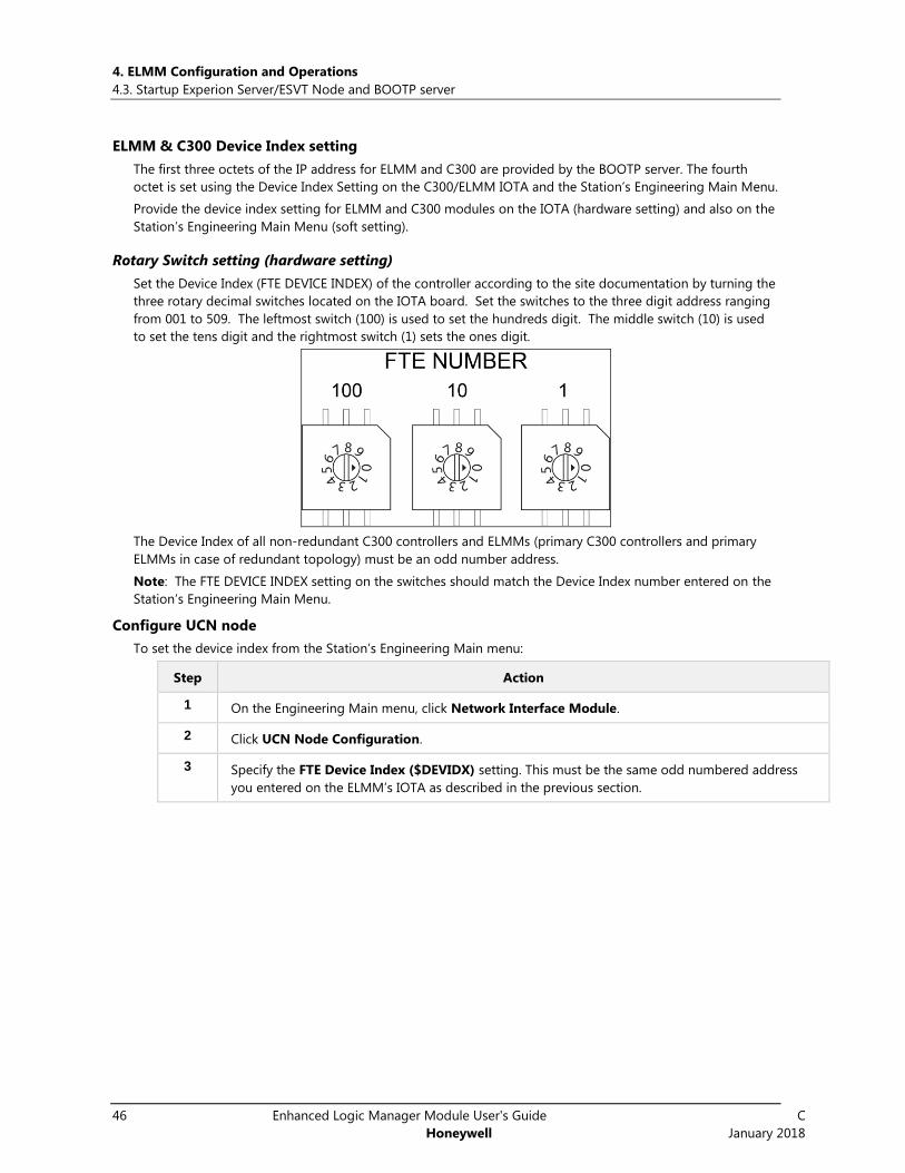
4. ELMM Configuration and Operations
4.3. Startup Experion Server/ESVT Node and BOOTP server
46 Enhanced Logic Manager Module User's Guide C
Honeywell January 2018
ELMM & C300 Device Index setting
The first three octets of the IP address for ELMM and C300 are provided by the BOOTP server. The fourth
octet is set using the Device Index Setting on the C300/ELMM IOTA and the Station’s Engineering Main Menu.
Provide the device index setting for ELMM and C300 modules on the IOTA (hardware setting) and also on the
Station’s Engineering Main Menu (soft setting).
Rotary Switch setting (hardware setting)
Set the Device Index (FTE DEVICE INDEX) of the controller according to the site documentation by turning the
three rotary decimal switches located on the IOTA board. Set the switches to the three digit address ranging
from 001 to 509. The leftmost switch (100) is used to set the hundreds digit. The middle switch (10) is used
to set the tens digit and the rightmost switch (1) sets the ones digit.
The Device Index of all non-redundant C300 controllers and ELMMs (primary C300 controllers and primary
ELMMs in case of redundant topology) must be an odd number address.
Note: The FTE DEVICE INDEX setting on the switches should match the Device Index number entered on the
Station’s Engineering Main Menu.
Configure UCN node
To set the device index from the Station’s Engineering Main menu:
Step Action
1 On the Engineering Main menu, click Network Interface Module.
2 Click UCN Node Configuration.
3 Specify the FTE Device Index ($DEVIDX) setting. This must be the same odd numbered address
you entered on the ELMM’s IOTA as described in the previous section.
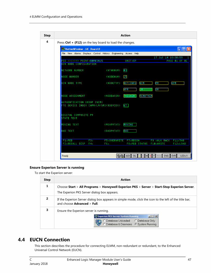
4 ELMM Configuration and Operations
C Enhanced Logic Manager Module User's Guide 47
January 2018 Honeywell
Step Action
4 Press Ctrl + (F12) on the key board to load the changes.
Ensure Experion Server is running
To start the Experion server:
Step Action
1 Choose Start > All Programs > Honeywell Experion PKS > Server > Start-Stop Experion Server.
The Experion PKS Server dialog box appears.
2 If the Experion Server dialog box appears in simple mode, click the icon to the left of the title bar,
and choose Advanced > Full.
3 Ensure the Experion server is running.
4.4 EUCN Connection This section describes the procedure for connecting ELMM, non-redundant or redundant, to the Enhanced
Universal Control Network (EUCN).

4. ELMM Configuration and Operations
4.4. EUCN Connection
48 Enhanced Logic Manager Module User's Guide C
Honeywell January 2018
UCN Node Address Selection
With ELMM, DIP switches are no longer used to provide the node address. Instead, you can set the node
address from the Station’s Engineering Main menu.
To specify a node address:
Step Action
1 On the Engineering Main menu, click Network Interface Module.
2 Click UCN Node Configuration.
3 Specify the following details to configure the UCN node:
Network Number
Node Number
UCN Node Type. Select LM
Node Assignment – Select ThisNIM
Device Index from rotary switch setting
4 Press Ctrl + (F12) on the key board to load the changes.
To modify a node address:
1 Reboot LMM.
2 Set the UCN node number using the same procedure as Specifying a node address.

4 ELMM Configuration and Operations
C Enhanced Logic Manager Module User's Guide 49
January 2018 Honeywell
4.5 Power on ELMM
ELMM start up
The ELMM module executes a series of tasks automatically when power is applied to the controller module.
These tasks include:
Power-On Self Test (POST) to verify the presence and integrity of the controller module hardware.
Initialization of the hardware and software environment
Determination of whether to transition to the application image, if present.
The following table summarizes the controller start up activity and execution of the POST upon power up.
Figure 4-1: ELMM Startup and Boot Mode indications illustrates the startup routine and Boot mode controller
states.
Step Action
1 The ELMM Power LED lights upon insertion of the module onto a powered IOTA board.
2 The ELMM boots up using firmware installed in the flash memory. (Initial firmware boot image is
installed in the factory.)
3 A Power-On Self Test (POST) is performed as part of the ELMM start up. Controller display shows
Tnnn, where nnn indicates the number of the test currently being executed during POST.
4 The Status LED briefly shows all of its colors (Red, Green, Orange), and then remains solid Red until
POST completes.
5 The four-character display walks through a series of horizontal and vertical bars, as well as several
brightness levels. Once completed successfully, the display indicates the progress of the POST.
See “ELMM faceplate indicators/displays” for a complete listing and description of the controller's
status indications and displays.
6 Progress of the POST is shown on the ELMM's faceplate display. If a fault occurs during POST, the test
halts and the display shows the test number (Tnnn) associated with the detected fault.
Corrective Action: If a fault occurs and halts the POST, then reset the controller and allow the POST to
execute once more. If the fault persists, then replace the failed controller module.
7 If no faults occur, POST continues to execute. Upon completion of POST, the ELMM determines
whether to transition to boot mode or application mode. If a valid application image is present in
the ELMM, then it is started in application mode, unless the controller has been commanded to
shutdown, or is rebooted into the FAIL state.
The Status LED indicates the state of the controller's associated hardware.
8 The controller indicates ‘-bp-’ on its display while it waits for a response from the BootP server
service. The BootP server supplies the ELMM its IP Address assignment and SNTP Server IP
addresses. If no response is received from the BootP server in 2 minutes, the ELMM will timeout.
Once the ELMM receives a response from the BootP server, ‘-TS-’ is indicated on the display while it
waits for a response from the configured time source. If the configured time source is not available,
the controller will attempt to connect with an alternate time source.

4. ELMM Configuration and Operations
4.5. Power on ELMM
50 Enhanced Logic Manager Module User's Guide C
Honeywell January 2018
Step Action
9 Action: Verify the correct Device Index is shown on the display (#nnn) and that there are no address
errors.
Address errors - The ELMM determines if any other module in the FTE network is using the same
Device Index. If another module is discovered with the same Device Index, the ELMM will not join
the FTE network but instead will enter the “no address” state and wait for a new Device Index to be
set.
If another node is discovered with the same IP Address, the controller will not join the FTE network
but instead will enter the “dup address” state and wait for a new Device Index to be set.
Action: If the Device Index is invalid, or any address error is displayed, see Reset Device Index and IP
address of a controller on from the C300 Controller User’s Guide and follow the procedure to
reassign the Device Index and IP addresses.
Once a valid IP Address is assigned, a redundant ELMM negotiates its redundancy role
(primary/secondary) with its partner module. See Stage 10.
10 The ELMM alternately displays its Device Index, redundancy role and execution state on the
controller's faceplate display.
Redundancy role - ‘nrdn’ may appear on the display to indicate that the ELMM’s redundancy role
has not been determined. For non-redundant controllers, the redundancy role is shown as ‘nrdn.’
Secondary controller first displays ‘nrdn’ until its redundancy role is determined. Once determined
the secondary controller indicates it is an unsynchronized secondary or synchronized secondary. The
secondary controller also shows the controller's execution state, which is ‘BKUP.’
The following illustrates the ELMM startup routine and the possible ELMM states when it is in the Boot mode.
Figure 4-1: ELMM Startup and Boot Mode indications

4 ELMM Configuration and Operations
C Enhanced Logic Manager Module User's Guide 51
January 2018 Honeywell
ELMM states in boot mode
At the conclusion of POST, the ELMM determines whether or not there is a valid Application Image present in
the controller and whether it should then transition to executing this Application image (Application mode) or
to continue in the Boot mode.
If the controller remains in the Boot mode, the controller then enters one of the states listed in
Controller in Boot mode table and joins the FTE network on which it resides. See Display indications
when controller is in boot mode table for a description of the faceplate indications when the
controller is operating in the boot mode.
If the controller transitions to the Application mode, the controller then joins the FTE network and
enters one of the operating states described in ELMM in Application mode table.
ELMM State Description
READY The controller received a command to remain in the boot mode to allow upgrading ELMM
Controller firmware. See the section, Upgrading ELMM Controller firmware in the C300
Controller User’s Guide for more details.
FAIL The controller detected a failure during startup.
Use the CTools utility to retrieve problem report logs from the controller for failure diagnosis.
ELMM states in application mode
The following table describes the controller states of the ELMM after it transitions to the application mode
after the LCN personality download. See Faceplate display information for a description of the faceplate
indications when the controller is operating in the application mode.
ELMM State Description
ALIVE The controller determined that application image exists and is waiting for
personality image to be loaded. You can perform an ELMM controller firmware
upgrade from this state, if required, as given in the section, Upgrading ELMM
Controller firmware in the C300 Controller User’s Guide.
IDLE The ELMM is configured as non-redundant or as redundant and has assumed the
primary redundancy role.
And…
Has retained a valid database from operations prior to startup
OK The ELMM is configured as non-redundant, or as redundant and has assumed the
primary redundancy role,
And…
Has retained a valid database from previous operations prior to startup
BKUP The ELMM is configured as redundant and has assumed the secondary redundancy
role. The ELMM moves to the BACKUP state.
See the section, Communications and system time faults during startup in the C300 Controller User’s Guide for
details on abnormal startup conditions in the ELMM/C300 controller due to communication and system time
faults. Corrective actions are provided to clear these conditions.

4. ELMM Configuration and Operations
4.5. Power on ELMM
52 Enhanced Logic Manager Module User's Guide C
Honeywell January 2018
ELMM faceplate indicators/displays
The faceplate of the ELMM contains four LEDs and a four-character alphanumeric display as shown in the
fo l lowing f igure. The labels on the LEDs are: Power, Status, FTE A and B.
The Status LED uses a 3-color scheme of red, green and orange. Generally, green indicates OK, red indicates
power up tests, a fault or failure, and orange indicates backup mode. Blinking LEDs indicate a soft or hard
failure and help to point to a problem. Soft failures also are indicated in other displays throughout the
system. The four-character display provides additional controller status information, see Faceplate display
information. Directly below the display are two LEDs that indicate FTE activity.
Figure 4-2: ELMM faceplate features
Power and Status LEDs
LED Indication Status/Description
Power LED
GREEN Steady Indicates the presence of 24Vdc to the controller module.
Status LED
GREEN Steady Non-redundant controller OK
Primary controller OK (primary and backup controllers may or may not
be synchronized)
ORANGE Steady Backup OK (controllers synchronized)
ORANGE
Blink off once per
second
Backup OK with Soft Failure (or controllers are not synchronized)
RED steady Self test (POST) in progress, or Self test has failed, Fault (hardware or
software diagnostic failed), or Hardware Watchdog Timer expired
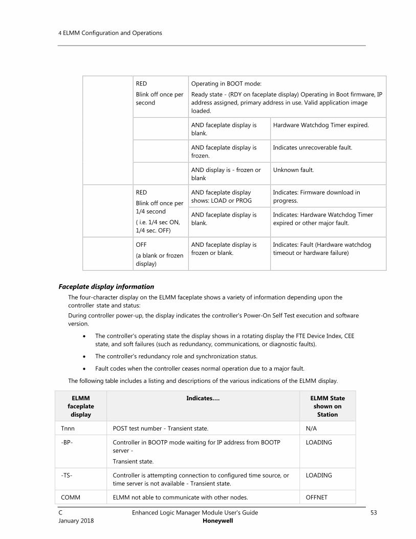
4 ELMM Configuration and Operations
C Enhanced Logic Manager Module User's Guide 53
January 2018 Honeywell
RED
Blink off once per
second
Operating in BOOT mode:
Ready state - (RDY on faceplate display) Operating in Boot firmware, IP
address assigned, primary address in use. Valid application image
loaded.
AND faceplate display is
blank.
Hardware Watchdog Timer expired.
AND faceplate display is
frozen.
Indicates unrecoverable fault.
AND display is - frozen or
blank
Unknown fault.
RED
Blink off once per
1/4 second
( i.e. 1/4 sec ON,
1/4 sec. OFF)
AND faceplate display
shows: LOAD or PROG
Indicates: Firmware download in
progress.
AND faceplate display is
blank.
Indicates: Hardware Watchdog Timer
expired or other major fault.
OFF
(a blank or frozen
display)
AND faceplate display is
frozen or blank.
Indicates: Fault (Hardware watchdog
timeout or hardware failure)
Faceplate display information
The four-character display on the ELMM faceplate shows a variety of information depending upon the
controller state and status:
During controller power-up, the display indicates the controller's Power-On Self Test execution and software
version.
The controller's operating state the display shows in a rotating display the FTE Device Index, CEE
state, and soft failures (such as redundancy, communications, or diagnostic faults).
The controller's redundancy role and synchronization status.
Fault codes when the controller ceases normal operation due to a major fault.
The following table includes a listing and descriptions of the various indications of the ELMM display.
ELMM
faceplate
display
Indicates…. ELMM State
shown on
Station
Tnnn POST test number - Transient state. N/A
-BP- Controller in BOOTP mode waiting for IP address from BOOTP
server -
Transient state.
LOADING
-TS- Controller is attempting connection to configured time source, or
time server is not available - Transient state.
LOADING
COMM ELMM not able to communicate with other nodes. OFFNET

4. ELMM Configuration and Operations
4.6. ELMM Configuration
54 Enhanced Logic Manager Module User's Guide C
Honeywell January 2018
See Note 1
TEST Factory Test mode - Non product state. LOADING
FAIL Failure in Module. FAILED
RDY Boot mode with application image ALIVE
LOAD Firmware load in progress LOADING
PROG Firmware flash in progress LOADING
IDLE Application mode with database loaded, IDLE
OK Application mode with database loaded, primary controller in RUN
state.
OK
BKUP Application mode with database loaded, secondary. BACKUP
NRDN Non-redundant ELMM OK
SYNC Application mode with database loaded. Initial sync in progress SYNC
NOSYNC Application mode with database loaded: NOSYNC
Note 1: The ELMM is ‘lonely’ (cables disconnected or network related problem). Startup halts until controller
can obtain an IP address or validate an internally retained IP address.
FTE activity LEDs
Each FTE port on the ELMM has one status LED. The bi-color FTE A and B LEDs indicate connectivity (link
present) and communication activity (transmit and/or receive). The following table describes the indications of
the FTE Status LEDs.
FTE A and B LEDs Indicates…
RED Link integrity check failed - No Ethernet signal detected, or cable is not connected.
OFF Link integrity is OK - Ethernet signal is present, but no activity on link.
Typically, every FTE node should show some activity. If the LED is observed for several
seconds, some activity should be seen.
Blinking GREEN Link integrity signal is present, with activity on link.
During normal operation the FTE A and B LEDs should be blinking at a variable rate
indicating normal network activity.
Moderate to high network traffic conditions may cause the LEDs to appear as steady
green.
4.6 ELMM Configuration Use the following procedure to load the redundant/non-redundant ELMM with LM personality and database.
Step Action
1 Load the odd-numbered ELMM with the LM personality and Checkpoint from the NET or Emulated
Drive. The ELMM status must go to LOADING, and then IDLE after the load is complete.

4 ELMM Configuration and Operations
C Enhanced Logic Manager Module User's Guide 55
January 2018 Honeywell
Step Action
If this is a redundant ELMM, then this is the new Primary ELMM. Do not load the Secondary ELMM at
this time.
2 Verify that the ELMM database is correct.
3 Invoke the Engineering Main Menu display by pressing the <CONTROL> and <HELP> keys on
the keyboard.
4 Start the process by selecting the NETWORK INTERFACE MODULE target on the Engineering
Main Menu display. This invokes the NIM Build Type Select Menu display.
5 Select the UCN NODE CONFIGURATION target to invoke the UCN Node Configuration display.

4. ELMM Configuration and Operations
4.6. ELMM Configuration
56 Enhanced Logic Manager Module User's Guide C
Honeywell January 2018
Step Action
6 Reconstitute the LM by entering the UCN NETWORK NUMBER, NODE NUMBER, UCN NODE
TYPE, and pressing the <CONTROL> and <F7> keys.
Note: As a better engineering practice, remove all Secondary ELMMs from the network and
reconfigure it after Primary ELMMs are running. For removing Secondary ELMMs, use UCN Node
configuration, change the BACKUP ELMM to NOT CONF and load by pressing Ctrl + F12.
7 Ensure that the node type is LM and then press enter.
8 Enter the FTE Device Index and press ENTER.
Note:
Use the FTE Device Index assigned to this ELMM in the EUCN Configuration Data Checklist.
Ensure that there are no errors.
Note: Refer to the EUCN Configuration Data Checklist file attached to this document.
The FTE Device Index entered must be the same as the FTE Device Index physically set in the
rotary switches of the ELMM FTE Interface Module.
For the redundant ELMM, the Secondary ELMM FTE Device Index is automatically set to the Primary
ELMM Device Index plus one.
9 Press the <CONTROL> and <F12> keys to load.
10 For the redundant ELMM, repeat steps 6, 7 and 9 for the secondary ELMM to come to the ALIVE
state.
11 Checkpoint the R6xx ELMM twice to NET and once to the Removable media (Emulated Disk).

4 ELMM Configuration and Operations
C Enhanced Logic Manager Module User's Guide 57
January 2018 Honeywell
Step Action
12 Startup the ELMM using either a Cold or Warm Start, as applicable.
13 If the ELMM is on other Logical UCNs, then repeat steps 3 through 11 for the ELMM on each of the
Logical UCNs.
14 Repeat Steps 1 through 12 for any other Primary ELMMs on this EUCN.
15 When all Primary ELMMs on the EUCN have been upgraded, loaded, configured, checkpointed and
started, the loading and start up procedure for Primary ELMMs are complete.
16 Shut down both ENIMs on this EUCN.
17 Load both ENIMs to pick up the FTE Device Index configuration for all Primary ELMMs on the EUCN.
18 For redundant ELMMs, perform the following steps for the Secondary ELMMs.
19 Confirm that the Secondary ELMM is in the ALIVE state.
20 Load the Secondary ELMM.
21 Confirm that the Secondary ELMM transitions to the BACKUP state.
22 Repeat steps 16 through 18 for all secondary ELMMs on this EUCN.
23 All LM to ELMM upgrade activities are complete for this EUCN.
24 You can now modify the ELMM point mix to update the IP parameters for communication with the
PLC, as needed. See the Parameter References Dictionary for information about IP parameters.
4.7 Displays This section describes ELMM specific displays.

4. ELMM Configuration and Operations
4.8. Enhanced Logic Manager Detailed Status Display
58 Enhanced Logic Manager Module User's Guide C
Honeywell January 2018
4.8 Enhanced Logic Manager Detailed Status Display This display is called up by selecting the ELMM node and the DETAIL STATUS target at the UCN STATUS
Display. From here, the various diagnostic displays can be accessed through the DETAIL STATUS target on the
lower right side of the screen.
Figure 6-3: Enhanced Logic Manager Detailed Status Display
Targets:
Swap Primary
This target provides the operator with a mechanism for requesting a redundancy switchover. It is functionally
equivalent to a target on the UCN Status display. It is visible when NODESTS is not equal to OFFNET for both
chassis. An ENTER is exposed to the right of this target that completes the request.
System Parameter: PMMCMD
UCN nn - Displays UCN network number and acts as a target for calling up (returning to) UCN STATUS display.
System Parameter: NTWKNUM
Range: 1 - 20
NN - Identifies node number (1-64) and acts as a target to select the chassis for calling additional detailed
status displays.
Detail Status - Acts in conjunction with the NN targets for calling up additional detailed status displays.
Node Status fields:
NODE nn - Node number of the ELMM.

4 ELMM Configuration and Operations
C Enhanced Logic Manager Module User's Guide 59
January 2018 Honeywell
System Parameter: NODENUM
Range: 1 – 64
TYPE tt - UCN Node Type.
System Parameter: NODETYP
Range: NotConfg, LM
(red.status) - Current redundancy status of the ELMM.
System Parameter: PMMOPER
Range: NON-REDUNDANT, PRIMARY, SECONDARY
(node status) - Current node status of the ELMM.
System Parameter: NODESTS
Range: ALIVE, IDLE, OK, PARTFAIL
Enhanced Logic Manager Module (ELMM) fields
A, B LEDs - Indicates the two FTE channels, with the small box used to indicate the active channel.
System Parameter: UCNRECHN
HW - Current version of ELMM hardware. Visible if the ELMM is on-line.
System Parameter: COMHWREV
Color: Cyan
FW - Current version of ELMM firmware. Visible if the ELMM is on-line.
System Parameter: COMFWREV
Color: Cyan
SW - Current version of ELMM software. Visible if the ELMM is on-line.
System Parameter: CONVERS, COMREV
Color: Cyan (Dot and Strings)
Processor fields
For ELMM, you can monitor the displays from the Experion Station. For information about monitoring the
displays, see the Operator’s Guide in the Experion documentation set.

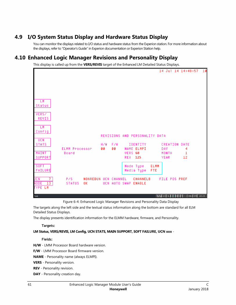
61 Enhanced Logic Manager Module User's Guide C
Honeywell January 2018
4.9 I/O System Status Display and Hardware Status Display You can monitor the displays related to I/O status and hardware status from the Experion station. For more information about
the displays, refer to “Operator’s Guide” in Experion documentation or Experion Station help.
4.10 Enhanced Logic Manager Revisions and Personality Display This display is called up from the VERS/REVIS target of the Enhanced LM Detailed Status Displays.
Figure 6-4: Enhanced Logic Manager Revisions and Personality Data Display
The targets along the left side and the textual status information along the bottom are standard for all ELM
Detailed Status Displays.
The display presents identification information for the ELMM hardware, firmware, and Personality.
Targets:
LM Status, VERS/REVIS, LM Config, UCN STATS, MAIN SUPPORT, SOFT FAILURE, UCN xxx -
Fields:
H/W - LMM Processor Board hardware version.
F/W - LMM Processor Board firmware version.
NAME - Personality name (always ELMPI).
VERS - Personality version.
REV - Personality revision.
DAY - Personality creation day.
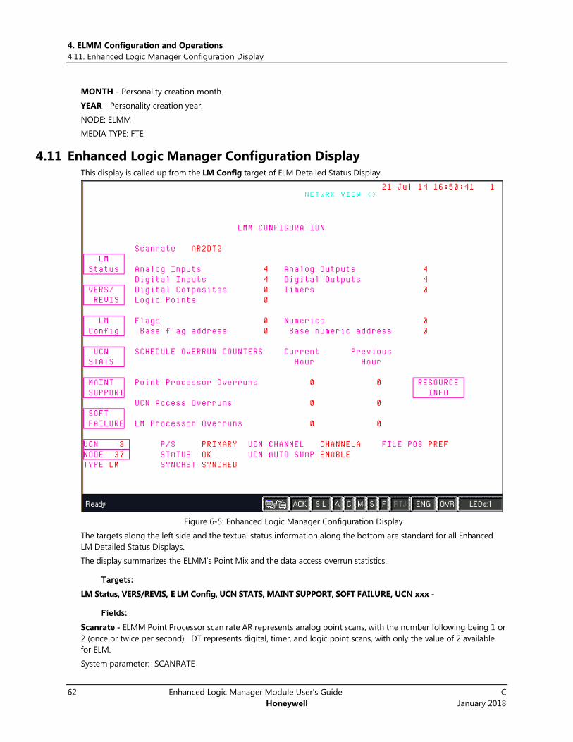
4. ELMM Configuration and Operations
4.11. Enhanced Logic Manager Configuration Display
62 Enhanced Logic Manager Module User's Guide C
Honeywell January 2018
MONTH - Personality creation month.
YEAR - Personality creation year.
NODE: ELMM
MEDIA TYPE: FTE
4.11 Enhanced Logic Manager Configuration Display This display is called up from the LM Config target of ELM Detailed Status Display.
Figure 6-5: Enhanced Logic Manager Configuration Display
The targets along the left side and the textual status information along the bottom are standard for all Enhanced
LM Detailed Status Displays.
The display summarizes the ELMM’s Point Mix and the data access overrun statistics.
Targets:
LM Status, VERS/REVIS, E LM Config, UCN STATS, MAINT SUPPORT, SOFT FAILURE, UCN xxx -
Fields:
Scanrate - ELMM Point Processor scan rate AR represents analog point scans, with the number following being 1 or
2 (once or twice per second). DT represents digital, timer, and logic point scans, with only the value of 2 available
for ELM.
System parameter: SCANRATE

4 ELMM Configuration and Operations
C Enhanced Logic Manager Module User's Guide 63
January 2018 Honeywell
Range: AR1DT2, AR2DT2
Analog Inputs - Number of AI points available.
System Parameter: NAISLOT
Range: 0-127/254
Analog Outputs - Number of AO points available.
System parameter: NAOSLOT
Range: 0-482/965
Digital Inputs - Number of DI points available.
System parameter: NDISLOT
Range: 0-1866
Digital Outputs - Number of DO points available.
System parameter: NDOSLOT
Range: 0-4000
Digital Composites - Number of DC points available.
System parameter: NDCSLOT
Range: 0-304
Timers - Number of Timer points available.
System parameter: NTIMER
Range: 0-700
Logic Points - Number of Logic points available.
System parameter: NLOGSLOT
Range: 0-14
Flags - Number of Flag points available.
System parameter: NFLAG
Range: 0-1024
Base Flag address - Starting address (least significant) of the block of flags.
System parameter: FLLSBA
Range: -1 (not configured), 0-4095
Numerics - Number of Numeric points available.
System parameter: NNUMERICS
Range: 0-1024
Base numeric address - Starting address (least significant) of the block of numerics.
System parameter: NNLSBA
Range: -1 (not configured), 4096 to 8191
Point Processor Overruns - Number of times ELMM was unable to complete a full scan of its points within the allotted
1/2 or 1 second. Such overruns are usually caused by a burst of activity (e.g., alarms or parameter requests) and
should only be a cause for concern if they occur frequently. If this number accumulates steadily, it usually means the
ELMM is receiving an excessive amount of parameter requests.
System parameter: CRPPXORN, LSPPXORN
UCN Access Overrun - Number of times ELMM was unable to collect UCN data in time to start its next scan. This
involves Logic Point inputs connected to points on other UCN nodes. Such overruns are usually caused by a burst
of activity (e.g., alarms or parameter requests) and should only be a cause for concern if they occur frequently.
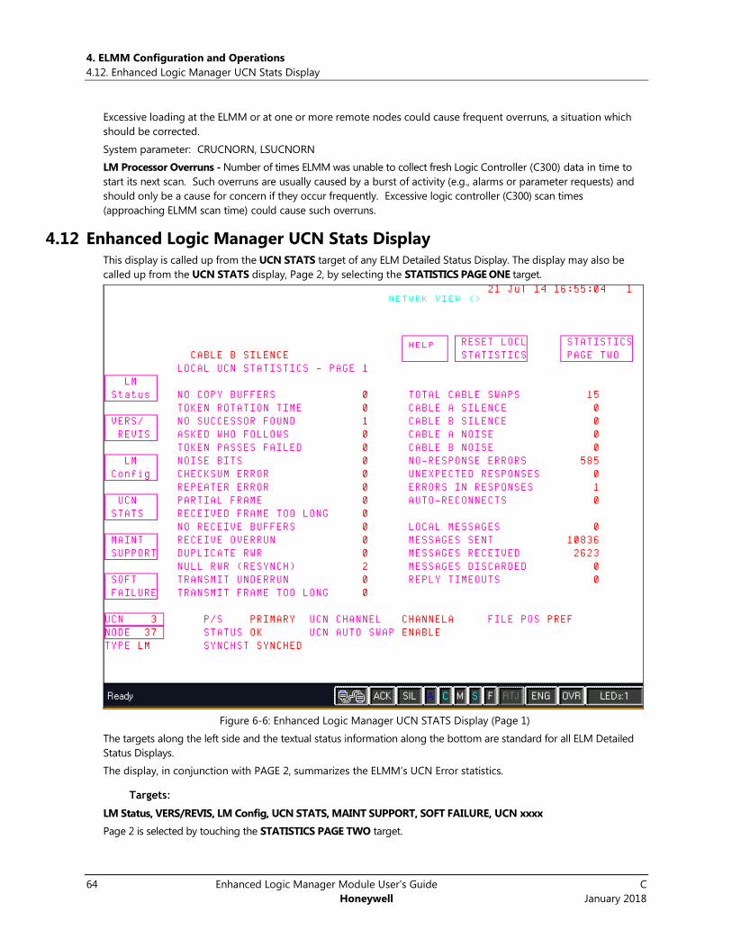
4. ELMM Configuration and Operations
4.12. Enhanced Logic Manager UCN Stats Display
64 Enhanced Logic Manager Module User's Guide C
Honeywell January 2018
Excessive loading at the ELMM or at one or more remote nodes could cause frequent overruns, a situation which
should be corrected.
System parameter: CRUCNORN, LSUCNORN
LM Processor Overruns - Number of times ELMM was unable to collect fresh Logic Controller (C300) data in time to
start its next scan. Such overruns are usually caused by a burst of activity (e.g., alarms or parameter requests) and
should only be a cause for concern if they occur frequently. Excessive logic controller (C300) scan times
(approaching ELMM scan time) could cause such overruns.
4.12 Enhanced Logic Manager UCN Stats Display This display is called up from the UCN STATS target of any ELM Detailed Status Display. The display may also be
called up from the UCN STATS display, Page 2, by selecting the STATISTICS PAGE ONE target.
Figure 6-6: Enhanced Logic Manager UCN STATS Display (Page 1)
The targets along the left side and the textual status information along the bottom are standard for all ELM Detailed
Status Displays.
The display, in conjunction with PAGE 2, summarizes the ELMM’s UCN Error statistics.
Targets:
LM Status, VERS/REVIS, LM Config, UCN STATS, MAINT SUPPORT, SOFT FAILURE, UCN xxxx
Page 2 is selected by touching the STATISTICS PAGE TWO target.
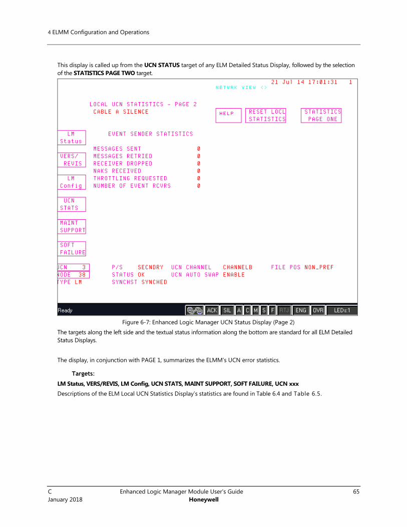
4 ELMM Configuration and Operations
C Enhanced Logic Manager Module User's Guide 65
January 2018 Honeywell
This display is called up from the UCN STATUS target of any ELM Detailed Status Display, followed by the selection
of the STATISTICS PAGE TWO target.
Figure 6-7: Enhanced Logic Manager UCN Status Display (Page 2)
The targets along the left side and the textual status information along the bottom are standard for all ELM Detailed
Status Displays.
The display, in conjunction with PAGE 1, summarizes the ELMM’s UCN error statistics.
Targets:
LM Status, VERS/REVIS, LM Config, UCN STATS, MAINT SUPPORT, SOFT FAILURE, UCN xxx
Descriptions of the ELM Local UCN Statistics Display’s statistics are found in Table 6.4 and Table 6.5.
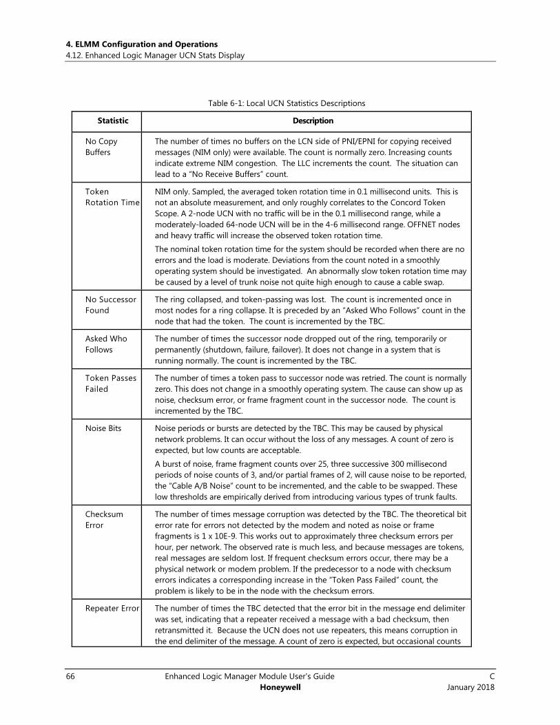
4. ELMM Configuration and Operations
4.12. Enhanced Logic Manager UCN Stats Display
66 Enhanced Logic Manager Module User's Guide C
Honeywell January 2018
Table 6-1: Local UCN Statistics Descriptions
Statistic Description
No Copy
Buffers
The number of times no buffers on the LCN side of PNI/EPNI for copying received
messages (NIM only) were available. The count is normally zero. Increasing counts
indicate extreme NIM congestion. The LLC increments the count. The situation can
lead to a “No Receive Buffers” count.
Token
Rotation Time
NIM only. Sampled, the averaged token rotation time in 0.1 millisecond units. This is
not an absolute measurement, and only roughly correlates to the Concord Token
Scope. A 2-node UCN with no traffic will be in the 0.1 millisecond range, while a
moderately-loaded 64-node UCN will be in the 4-6 millisecond range. OFFNET nodes
and heavy traffic will increase the observed token rotation time.
The nominal token rotation time for the system should be recorded when there are no
errors and the load is moderate. Deviations from the count noted in a smoothly
operating system should be investigated. An abnormally slow token rotation time may
be caused by a level of trunk noise not quite high enough to cause a cable swap.
No Successor
Found
The ring collapsed, and token-passing was lost. The count is incremented once in
most nodes for a ring collapse. It is preceded by an “Asked Who Follows” count in the
node that had the token. The count is incremented by the TBC.
Asked Who
Follows
The number of times the successor node dropped out of the ring, temporarily or
permanently (shutdown, failure, failover). It does not change in a system that is
running normally. The count is incremented by the TBC.
Token Passes
Failed
The number of times a token pass to successor node was retried. The count is normally
zero. This does not change in a smoothly operating system. The cause can show up as
noise, checksum error, or frame fragment count in the successor node. The count is
incremented by the TBC.
Noise Bits Noise periods or bursts are detected by the TBC. This may be caused by physical
network problems. It can occur without the loss of any messages. A count of zero is
expected, but low counts are acceptable.
A burst of noise, frame fragment counts over 25, three successive 300 millisecond
periods of noise counts of 3, and/or partial frames of 2, will cause noise to be reported,
the “Cable A/B Noise” count to be incremented, and the cable to be swapped. These
low thresholds are empirically derived from introducing various types of trunk faults.
Checksum
Error
The number of times message corruption was detected by the TBC. The theoretical bit
error rate for errors not detected by the modem and noted as noise or frame
fragments is 1 x 10E-9. This works out to approximately three checksum errors per
hour, per network. The observed rate is much less, and because messages are tokens,
real messages are seldom lost. If frequent checksum errors occur, there may be a
physical network or modem problem. If the predecessor to a node with checksum
errors indicates a corresponding increase in the “Token Pass Failed” count, the
problem is likely to be in the node with the checksum errors.
Repeater Error The number of times the TBC detected that the error bit in the message end delimiter
was set, indicating that a repeater received a message with a bad checksum, then
retransmitted it. Because the UCN does not use repeaters, this means corruption in
the end delimiter of the message. A count of zero is expected, but occasional counts
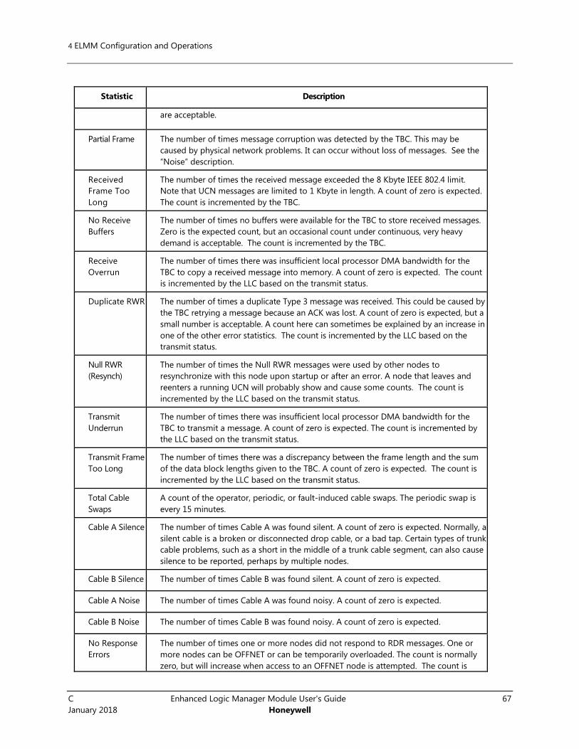
4 ELMM Configuration and Operations
C Enhanced Logic Manager Module User's Guide 67
January 2018 Honeywell
Statistic Description
are acceptable.
Partial Frame The number of times message corruption was detected by the TBC. This may be
caused by physical network problems. It can occur without loss of messages. See the
“Noise” description.
Received
Frame Too
Long
The number of times the received message exceeded the 8 Kbyte IEEE 802.4 limit.
Note that UCN messages are limited to 1 Kbyte in length. A count of zero is expected.
The count is incremented by the TBC.
No Receive
Buffers
The number of times no buffers were available for the TBC to store received messages.
Zero is the expected count, but an occasional count under continuous, very heavy
demand is acceptable. The count is incremented by the TBC.
Receive
Overrun
The number of times there was insufficient local processor DMA bandwidth for the
TBC to copy a received message into memory. A count of zero is expected. The count
is incremented by the LLC based on the transmit status.
Duplicate RWR The number of times a duplicate Type 3 message was received. This could be caused by
the TBC retrying a message because an ACK was lost. A count of zero is expected, but a
small number is acceptable. A count here can sometimes be explained by an increase in
one of the other error statistics. The count is incremented by the LLC based on the
transmit status.
Null RWR
(Resynch)
The number of times the Null RWR messages were used by other nodes to
resynchronize with this node upon startup or after an error. A node that leaves and
reenters a running UCN will probably show and cause some counts. The count is
incremented by the LLC based on the transmit status.
Transmit
Underrun
The number of times there was insufficient local processor DMA bandwidth for the
TBC to transmit a message. A count of zero is expected. The count is incremented by
the LLC based on the transmit status.
Transmit Frame
Too Long
The number of times there was a discrepancy between the frame length and the sum
of the data block lengths given to the TBC. A count of zero is expected. The count is
incremented by the LLC based on the transmit status.
Total Cable
Swaps
A count of the operator, periodic, or fault-induced cable swaps. The periodic swap is
every 15 minutes.
Cable A Silence The number of times Cable A was found silent. A count of zero is expected. Normally, a
silent cable is a broken or disconnected drop cable, or a bad tap. Certain types of trunk
cable problems, such as a short in the middle of a trunk cable segment, can also cause
silence to be reported, perhaps by multiple nodes.
Cable B Silence The number of times Cable B was found silent. A count of zero is expected.
Cable A Noise The number of times Cable A was found noisy. A count of zero is expected.
Cable B Noise The number of times Cable B was found noisy. A count of zero is expected.
No Response
Errors
The number of times one or more nodes did not respond to RDR messages. One or
more nodes can be OFFNET or can be temporarily overloaded. The count is normally
zero, but will increase when access to an OFFNET node is attempted. The count is

4. ELMM Configuration and Operations
4.12. Enhanced Logic Manager UCN Stats Display
68 Enhanced Logic Manager Module User's Guide C
Honeywell January 2018
Statistic Description
incremented by the LLC based on the transmit status. The count is not incremented if
the TBC is successful on its automatic retry.
Unexpected
Responses
The number of times MAC control was not correct for an RWR response message (such
as the wrong node number in a response). This indicates network contention or
corruption within a node. A count of zero is expected. It also indicates the number of
times SAPs were not as expected. The count is incremented by the LLC based on the
transmit status and/or message header contents.
Errors In
Responses
The number of times the LLC part of an RWR response was incorrect. This can indicate
corruption in a node, or network contention. A count of zero is expected. The count is
incremented by the LLC based on the transmit status and/or message size, or header
contents.
Auto-
Reconnects
The number of times this node attempted to reconnect to the UCN after a serious
UCN communication fault.
Local
Messages
The number of messages between tasks in this node. The count is always incrementing
in a NIM, zero in a LM.
Messages Sent The number of messages sent from this node. The count does not include automatic
TBC retries or driver retries.
Messages
Received
The number of messages received by this node.
Messages
Discarded
The number of messages discarded by this node. Normally zero, but may occasionally
count occurrences of:
A reply received after the reply timeout period expired;
1. A duplicate reply message caused by retry because the immediate ACK of
a reply message was not received by the node sending the reply message
2. A bad protocol version
1. A message for an inactive function
2. A message from a non configured node (NIM only)
Reply
Timeouts
The number of times a reply was not received during the user-specified timeout
interval. If a Type 3 request, the request was received and ACK’d, but the reply was not
received. It may be caused by receive buffer overload in the local node, or the remote
node failed after the ACK but before sending the reply.
Table 6-2: Event Sender Statistics Descriptions
Statistic Description
Messages Sent
The number of messages sent, not including retries. When an idle or running event
sender has no new events to send, it resends the last message every 10 seconds so that
the NIM can watchdog event delivery.
Messages
Retried
The number of messages retried caused by no response, lost ACK, or NAK. The count is
normally zero unless event overload has occurred. The count normally correlates with the
“NAKs Received” count in the event senders.

4 ELMM Configuration and Operations
C Enhanced Logic Manager Module User's Guide 69
January 2018 Honeywell
Receiver
Dropped
The number of times any event receiver failed to respond to a message after retries, and
thus was removed from the retry list. Retries are no longer performed to nonresponding
event receivers. The count is normally zero in NIMs. A single count in each event sender
can accompany a NIM failure (primary and secondary).
NAKs Received
The number of times a message was temporarily not accepted by an event receiver.
Retries are performed after a delay. The count is normally zero, except under heavy event
traffic.
Throttling
Requested
The number of times this node was requested to delay before sending another message.
A count of zero is normal, except under heavy event traffic. The count corresponds to the
“At Node Throttle Threshold” statistic in the event senders.
Number Of
Event Rcvrs
The number of event receivers that are currently acknowledging events from this event
sender. In LMs this count is normally the number of primary NIMs.

4. ELMM Configuration and Operations
4.13. Maintenance Support Displays Communications Error Block Display for Enhanced Logic Manager
70 Enhanced Logic Manager Module User's Guide C
Honeywell January 2018
4.13 Maintenance Support Displays Communications Error Block Display for
Enhanced Logic Manager This display is called up from the MAINT SUPPORT target of any ELM Detailed Status Display, or by selecting the
COMMUNCTN ERROR BLK target within the NODE STS INFO display.
Figure 6-8: Enhanced Logic Manager Communications Error Block Display
The targets along the left side and the textual status information along the bottom are standard for all ELM Detailed
Status Displays.
The display presents the content of an error buffer within the LMM. This display is normally used to assist product
support personnel during fault situations. Please contact TAC for more details.
Targets:
LM Status, VERS/REVIS, LM Config, UCN STATS, MAINT SUPPORT, SOFT FAILURE, UCN xxx
COMMUNCTN ERROR BLK - target for this display.
NODE STS INFO - target for NODE STATUS (NIM version) display.
86B86BNode Status Information Display
This display is called up from within the MAINT SUPPORT target of any ELM Detailed Status Display, by selecting the
NODE STST INFO target within that display.
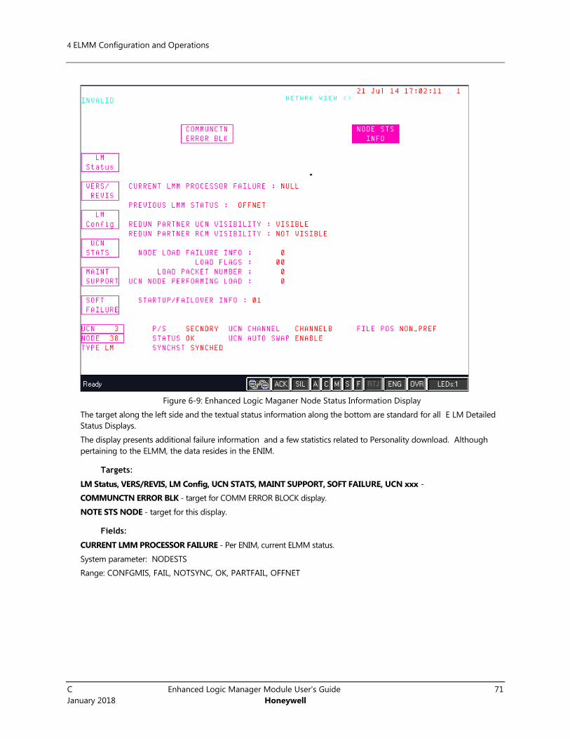
4 ELMM Configuration and Operations
C Enhanced Logic Manager Module User's Guide 71
January 2018 Honeywell
Figure 6-9: Enhanced Logic Maganer Node Status Information Display
The target along the left side and the textual status information along the bottom are standard for all E LM Detailed
Status Displays.
The display presents additional failure information and a few statistics related to Personality download. Although
pertaining to the ELMM, the data resides in the ENIM.
Targets:
LM Status, VERS/REVIS, LM Config, UCN STATS, MAINT SUPPORT, SOFT FAILURE, UCN xxx -
COMMUNCTN ERROR BLK - target for COMM ERROR BLOCK display.
NOTE STS NODE - target for this display.
Fields:
CURRENT LMM PROCESSOR FAILURE - Per ENIM, current ELMM status.
System parameter: NODESTS
Range: CONFGMIS, FAIL, NOTSYNC, OK, PARTFAIL, OFFNET

5. ELMM Troubleshooting
5.1. Hardware Diagnostics
72 Enhanced Logic Manager Module User's Guide C
Honeywell January 2018
5. ELMM Troubleshooting
5.1 Hardware Diagnostics
Start-up Self-Test
A power on self test (POST) is performed when the ELMM is powered on. See Power on ELMM and ensure the
sequence of steps is correctly performed.
5.2 Troubleshooting scenarios The following are the troubleshooting scenarios for ELMM.
Scenario Description Cause Solution
IP conflict Two nodes with same
Device Index (IP
address).
Device Index is not
unique in two nodes
Ensure Device Index is unique in
each node.
CF9 firmware revision CF9 firmware version is
not up-to-date.
CF9 firmware version is
below FF.
Upgrade CF9 firmware version to
FF or above.
PCDI Communication failure ELMM and C300 fail to
communicate, which
will indicate as socket
error or protocol
errors in ELMM node.
Many causes that are
scrutinized within the
corrective action.
If socket error or protocol errors
appear, then go to Control
Builder to see the failed PCDI
channels and then correct the
error.
Not Synchronized The primary and/or
secondary Control
Processor Module
(CPM) generates the
Not Synchronized
Diagnostic Alarm
notification either
upon redundancy
startup (i.e. detection
of Redundancy
Module (RM)) or
detection of loss-of-
synchronization. The
primary and secondary
CPM generates the
Not Synchronized
return-to-normal
notification once
synchronization is
achieved.
Many causes that are
scrutinized within the
corrective action
Ensure redundancy cable is
present and attached to both the
primary and secondary RM
87B87BSoft Failure Display for Enhanced Logic Manager
This display is called up from the SOFT FAILURE target of any ELM Detailed Status Display.
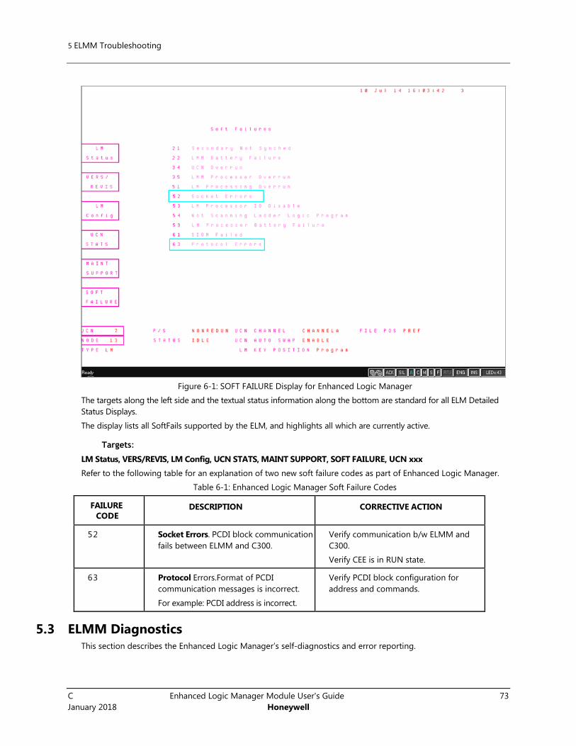
5 ELMM Troubleshooting
C Enhanced Logic Manager Module User's Guide 73
January 2018 Honeywell
Figure 6-1: SOFT FAILURE Display for Enhanced Logic Manager
The targets along the left side and the textual status information along the bottom are standard for all ELM Detailed
Status Displays.
The display lists all SoftFails supported by the ELM, and highlights all which are currently active.
Targets:
LM Status, VERS/REVIS, LM Config, UCN STATS, MAINT SUPPORT, SOFT FAILURE, UCN xxx
Refer to the following table for an explanation of two new soft failure codes as part of Enhanced Logic Manager.
Table 6-1: Enhanced Logic Manager Soft Failure Codes
FAILURE
CODE DESCRIPTION CORRECTIVE ACTION
52 Socket Errors. PCDI block communication
fails between ELMM and C300.
Verify communication b/w ELMM and
C300.
Verify CEE is in RUN state.
63 Protocol Errors.Format of PCDI
communication messages is incorrect.
For example: PCDI address is incorrect.
Verify PCDI block configuration for
address and commands.
5.3 ELMM Diagnostics This section describes the Enhanced Logic Manager’s self-diagnostics and error reporting.

5. ELMM Troubleshooting
5.4. Using CTools to capture diagnostic data
74 Enhanced Logic Manager Module User's Guide C
Honeywell January 2018
Checking faceplate display and LEDs
Check the ELMM Controller's 4-character display and ELMM/IOTA LED indications and compare results with data
in the “Processor fields’’ . For more information about “Processor fields”, see Enhanced Logic Manager Detailed
Status Display.
Fault classifications Controller display LEDs
Hard/Severe Failures FAIL alternating with a four-digit error code
03A7 ---Hardware failure
Any other four digit code= possible software fault
A blank display indicates a Watchdog Timer timeout
Status LED = RED
Installation-Startup Failures Tnnn indicating the test number that the controller was performing when a fault was detected.
-bp- BootP service not available
-TS- Time source not available.
Status LED = solid RED
Hardware Watchdog Timer
Expired
Blank Status LED= RED blinking off every \
second.
FTE LEDs = RED
Communications Failure COMM indicating no communications with other nodes.
FTE LEDs = RED
5.4 Using CTools to capture diagnostic data You can use the CTools utility to capture diagnostic data used to examine the operating conditions within the
controller. This data also can be analyzed to determine the cause of an error or fault. The following data can be
captured using CTools:
Trace Log
Registers
SSP
Call Stack
Instructions
You can also use the CTool utility to capture crash block or user log diagnostic data associated with a given Series
C device as well as view history log data. Remember the following while using the CTool utility.
You must run one instance of CTools on either the primary or backup Experion server.
The first time you launch the CTools utility, it may take up to 40 seconds before the Series C devices on
the network appear in the module listing table.
CTools detects when modules are added or removed as well as when I/O Link cables are added or
removed, which affect the presence of I/O Modules.
You can click the Save User Log button on the Diagnostic Capture dialog to save a user readable file
listing firmware download data to a directory location of your choice.
You can click the Save Data button on the Diagnostic Capture dialog to save a crash information file to a
directory location of your choice that can be transferred to Honeywell TAC for fault analysis.

5 ELMM Troubleshooting
C Enhanced Logic Manager Module User's Guide 75
January 2018 Honeywell
Prerequisites
You have installed the Experion R410.1/R430.1 software, configured the base IP address as well as
addresses for time servers through the System Preferences selection in the Control Builder's Tools menu,
and set the Device Index number for each of ELMM and FIM4 through the Binary Coded Decimal
switches on its input/output termination assembly (IOTA).
To capture diagnostic data using CTools
To capture the diagnostic data using CTools, refer to “C200/C200E Troubleshooting and Maintenance Guide” in
Experion documentation.
5.5 FTESTS Cable Error scenarios for Enhanced Logic Manager The following sections show how the FTE cable faults are reported on the $FTESTS displays:
ATTENTION
The term “$FTESTS displays” include both $FTESTS1 and $FTESTS2 displays.
$FTESTS1 display shows the FTE status of the UCN nodes assigned to the selected
ENIM, and is filtered by the UCN Node Number, which has a range of 01-64.
$FTESTS2 display shows the status of all the FTE devices in the FTE community and is
filtered by the FTE Device Index, which has a range of 01-509.
Table 2 EHPM Cable Faults
Error scenario $FTESTS displays
(this ELMM)
$FTESTS displays
(all other EUCN nodes)
No FTE cable problems
If FTE cable A on an
ELMM node has a
problem
If FTE cable B on an ELMM
node has a problem
If both FTE cable A and
FTE cable B on an ELMM
node have a problem
Table 3 ELMM Cable Faults
Error scenario $FTESTS displays
(this ELMM)
$FTESTS displays
(all other EUCN nodes)
If FTE cable A on an
ELMM has a problem

5. ELMM Troubleshooting
5.6. Known Issues
76 Enhanced Logic Manager Module User's Guide C
Honeywell January 2018
If FTE cable B on an ELMM
has a problem
If both FTE cable A and
FTE cable B on an ELMM
have a problem
Single ELMM:
Redundant ELMM:
ATTENTION
If you come across an LCN system alarm that can be traced to a UCN cable failure (indicated by
the word “FAIL” next to the text UCN CABLE STATUS on the UCN Status Display) and the
ELMM's A/B cables are backlit/red.
To resolve this, perform the following procedure:
1. Go to the $FTESTS2 display and then check the FTE composite status.
2. If the composite status for cables is not OK, then scroll through all the 8 pages of $FTESTS2
display to determine the node that is causing cable problems and then resolve.
Note: Select the RESET STATS target to reset either disjoined or force-failed nodes before the
FTE composite status can be resolved.
LCN system alarm can also be caused by a switch uplink failure (for example, CF9), check your
upper-level network topology to confirm this.
5.6 Known Issues A few known issues with workarounds where available are presented in this section.
Issue Description Workaround
LADDER SAVE and LADDER
LOAD options are displayed on
the UCN Status display for
LOAD/SAVE RESTORE option
while performing Checkpoint
Restore of ELMM.
LADDER SAVE and LADDER
LOAD options are displayed
even though they are not
applicable for ELMM. During the
Checkpoint Restore operation,
these targets are disabled.
There is no known workaround
Non-redundant ELMM shows
PARTFAIL since the firmware
cannot determine whether the
ELMM configured is redundant
The Non-redundant ELMM
shows PARTFAIL status, since
currently there is no way the
firmware can determine
There is no known workaround

5 ELMM Troubleshooting
C Enhanced Logic Manager Module User's Guide 77
January 2018 Honeywell
or non-redundant. whether the ELMM configured
is redundant or non-redundant.
The PARTFAIL status on the
non-redundant node can be
ignored. No functional impact.
A system error is reported on
the SEJ whenever an ELMM
node comes up
A system error is reported on
the SEJ whenever an ELMM
node comes up. This is due to
the mismatch in the event
packet format between the
NIM and ELMM. No
functional impact
There is no known workaround
NIM fails to recognize the
secondary ELMM module
during the double FTE cable
fault scenario.
NIM fails to recognize the
secondary ELMM module
during the double FTE cable
fault scenario
Reboot the Secondary ELMM

5. ELMM Troubleshooting
5.6. Known Issues
78 Enhanced Logic Manager Module User's Guide C
Honeywell January 2018
Issue Description Workaround
Non-redundant ELMM is
displayed as primary on the
UCN Status Display which
causes several no-response
errors
The Non-redundant ELMM is
displayed as primary instead of
non-redundant on the UCN
Status Display and hence it
attempts to communicate with
the secondary ELMM which
does not exist. This results in
several no-response errors
There is no known workaround
A loss of control and/or loss of
view may occur on running
EUCN nodes if the Device Index
($DEVIDX) of an existing node is
used while loading the EUCN
node specific configuration to a
newly configured EUCN node.
For example, on a running
ELMM (for example, EUCN=04,
ELMM=07, $DEVIDX=33), if the
user reconstitutes the UCN
configuration on the ELMM, and
changes the ELMM node
number (for example, 07), but
retains the same $DEVIDX value
(for example, 33) on the same
UCN number (for example, 04),
and then loads this
configuration, this may result in
a loss of control and/or loss of
view for all the EUCN nodes.
While reconfiguring an EUCN
node, if there is a change in the
Device Index of a running EUCN
node, DEB throws a warning
indicating that a loss of control
and/or loss of view may occur
on an EUCN node. Use caution
while reconfiguring an EUCN
node
If you need assistance to
perform this procedure, contact
Honeywell TAC.
Use caution when making
ONLINE changes to the Device
Index ($DEVIDX) value on a
running EUCN system. This may
result in loss of control and/or
loss of view for the EUCN nodes
if the same Device Index and
the EUCN node numbers are
used that exist on a pre-existing
EUCN (only the EUCN node
number is different).
If this accidentally occurs, to
recover:
• Reload the original EUCN’s
UCN Device Specific
configuration.
• Configure a unique Device
Index for the new EUCN node.
• Re-flash the firmware on the
EPNI2 board and then reboot
ENIM.
A unique Device Index is
required for each and every
node in the FTE Community. If
you attempt to configure a
duplicate Device Index, then the
last one loaded replaces the
original.
ELMM node status goes to FAIL
status when firmware is loading.
If you load firmware to ELMM
through Ctools when node
status is OK, ELMM node goes
to FAIL status although this
status change must not occur
until reboot.
Loading the firmware to ELMM
through CTools when node
status is OK must be blocked.
It is currently not blocked.
The reason for blocking
firmware load in ELMM in OK

5 ELMM Troubleshooting
C Enhanced Logic Manager Module User's Guide 79
January 2018 Honeywell
state is because the firmware
load takes effect immediately
and causes ELMM to got to FAIL
status.

Honeywell Process Solutions
1860 W. Rose Garden Lane
Phoenix, AZ 85027 USA