elements of electrical · pdf filelecture notes elements of electrical machines 2 disclaimer...
TRANSCRIPT
Lecture Notes Elements of Electrical Machines
1
VEER SURENDRA SAI UNIVERSITY OF TECHNOLOGY BURLA, ODISHA, INDIA
DEPARTMENT OF ELECTRICAL ENGINEERING
Elements of Electrical Machines
Lecture Notes
Subject Code: BEE 1301
For 3rd
Semester Mechanical Engineering and Production Engineering students
Lecture Notes Elements of Electrical Machines
2
Disclaimer
This document does not claim any originality and cannot be used as a substitute for prescribed
textbooks. The information presented here is merely a collection by the committee members for their
respective teaching assignments. Various sources as mentioned at the reference of the document as
well as freely available material from internet were consulted for preparing this document. The
ownership of the information lies with the respective authors or institutions. Further, this document is
not intended to be used for commercial purpose and the committee members are not accountable for
any issues, legal or otherwise, arising out of use of this document. The committee members make no
representations or warranties with respect to the accuracy or completeness of the contents of this
document and specifically disclaim any implied warranties of merchantability or fitness for a particular
purpose. The committee members shall be liable for any loss of profit or any other commercial
damages, including but not limited to special, incidental, consequential, or other damages.
Lecture Notes Elements of Electrical Machines
3
Veer Surendra Sai University of Technology, Odisha, Burla, India
Department of Electrical Engineering,
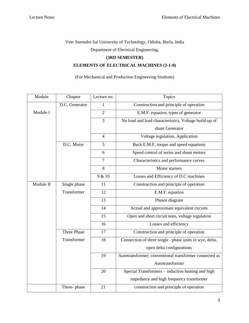
(3RD SEMESTER)
ELEMENTS OF ELECTRICAL MACHINES (3-1-0)
(For Mechanical and Production Engineering Students)
Module Chapter Lecture no. Topics
Module I
D.C. Generator 1 Construction and principle of operation
2 E.M.F. equation, types of generator
3 No load and load characteristics, Voltage build-up of
shunt Generator
4 Voltage regulation, Application
D.C. Motor 5 Back E.M.F, torque and speed equations
6 Speed control of series and shunt motors
7 Characteristics and performance curves
8 Motor starters
9 & 10 Losses and Efficiency of D.C machines
Module II Single phase
Transformer
11 Construction and principle of operation
12 E.M.F. equation
13 Phasor diagram
14 Actual and approximate equivalent circuits
15 Open and short circuit tests, voltage regulation
16 Losses and efficiency
Three Phase
Transformer
17 Construction and principle of operation
18 Connection of three single –phase units in wye, delta,
open delta configurations
19 Autotransformer; conventional transformer connected as
Autotransformer
20 Special Transformers – induction heating and high
impedance and high frequency transformer
Three- phase 21 construction and principle of operation
Lecture Notes Elements of Electrical Machines
4
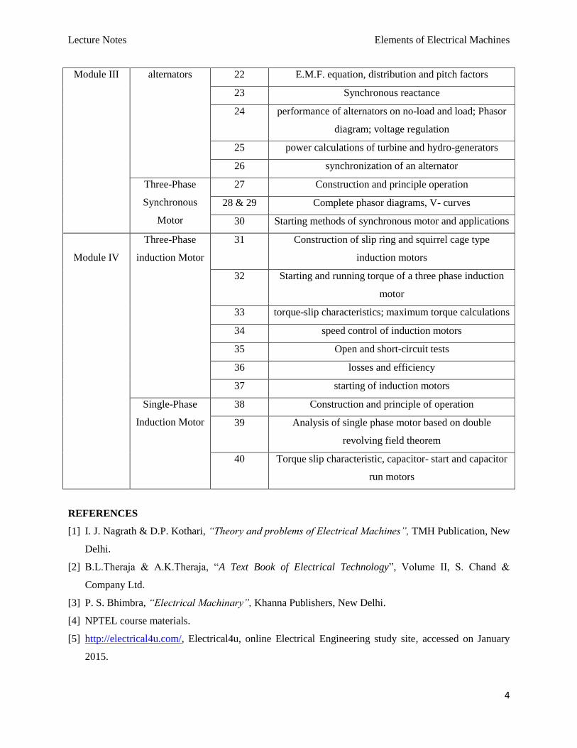
Module III alternators 22 E.M.F. equation, distribution and pitch factors
23 Synchronous reactance
24 performance of alternators on no-load and load; Phasor
diagram; voltage regulation
25 power calculations of turbine and hydro-generators
26 synchronization of an alternator
Three-Phase
Synchronous
Motor
27 Construction and principle operation
28 & 29 Complete phasor diagrams, V- curves
30 Starting methods of synchronous motor and applications
Module IV
Three-Phase
induction Motor
31 Construction of slip ring and squirrel cage type
induction motors
32 Starting and running torque of a three phase induction
motor
33 torque-slip characteristics; maximum torque calculations
34 speed control of induction motors
35 Open and short-circuit tests
36 losses and efficiency
37 starting of induction motors
Single-Phase
Induction Motor
38 Construction and principle of operation
39 Analysis of single phase motor based on double
revolving field theorem
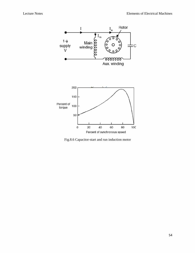
40 Torque slip characteristic, capacitor- start and capacitor
run motors
REFERENCES
[1] I. J. Nagrath & D.P. Kothari, “Theory and problems of Electrical Machines”, TMH Publication, New
Delhi.
[2] B.L.Theraja & A.K.Theraja, “A Text Book of Electrical Technology”, Volume II, S. Chand &
Company Ltd.
[3] P. S. Bhimbra, “Electrical Machinary”, Khanna Publishers, New Delhi.
[4] NPTEL course materials.
[5] http://electrical4u.com/, Electrical4u, online Electrical Engineering study site, accessed on January
2015.
Lecture Notes Elements of Electrical Machines
5
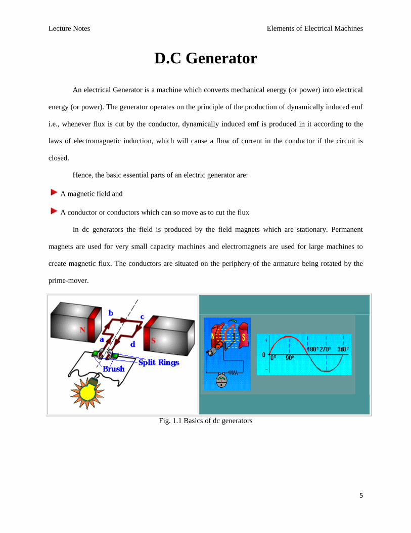
D.C Generator
An electrical Generator is a machine which converts mechanical energy (or power) into electrical
energy (or power). The generator operates on the principle of the production of dynamically induced emf
i.e., whenever flux is cut by the conductor, dynamically induced emf is produced in it according to the
laws of electromagnetic induction, which will cause a flow of current in the conductor if the circuit is
closed.
Hence, the basic essential parts of an electric generator are:
A magnetic field and
A conductor or conductors which can so move as to cut the flux
In dc generators the field is produced by the field magnets which are stationary. Permanent
magnets are used for very small capacity machines and electromagnets are used for large machines to
create magnetic flux. The conductors are situated on the periphery of the armature being rotated by the
prime-mover.
Fig. 1.1 Basics of dc generators
Lecture Notes Elements of Electrical Machines
6
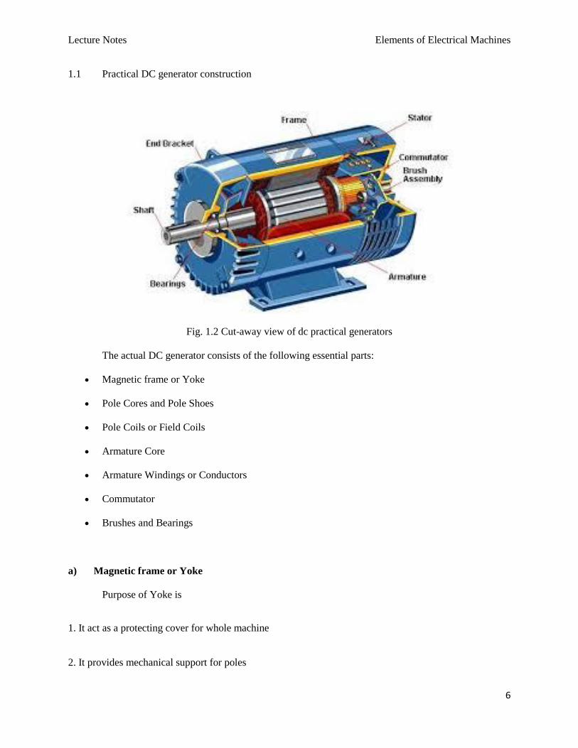
1.1 Practical DC generator construction
Fig. 1.2 Cut-away view of dc practical generators
The actual DC generator consists of the following essential parts:
Magnetic frame or Yoke
Pole Cores and Pole Shoes
Pole Coils or Field Coils
Armature Core
Armature Windings or Conductors
Commutator
Brushes and Bearings
a) Magnetic frame or Yoke
Purpose of Yoke is
1. It act as a protecting cover for whole machine
2. It provides mechanical support for poles
Lecture Notes Elements of Electrical Machines
7
3. It carries the magnetic flux produced by poles
b) Pole Cores and Pole Shoes
The field magnets consist of pole cores and pole shoes. The Pole shoes serve two purposes:
1. They spread out the flux in the air gap
2. They support the exciting coils
c) Armature
When current is passed through field coils, they electro-magnetize the poles which produce
the necessary flux.
The Armature serves two purposes:
1. Armature houses the armature conductors or coils
2. It provides low reluctance path for flux
It is drum shaped and is built up of laminations made sheet steel to reduce eddy current loss.
Slots are punched on the outer periphery of the disc. The Armature windings or conductors are
wound in the form of flat rectangular coils and are placed in the slots of the Armature. The Armature
windings are insulated from the armature body by insulating materials.
d) Commutator and brushes
The function of Commutator is to facilitate collection of current from the armature
conductors and converts the alternating current induced in the armature conductors into
unidirectional current in the external load circuit. The commutator is made up of insulated copper
segments. Two brushes are pressed to the commutator to permit current flow. The Brushes are made
of carbon or Graphite. Bearings are used for smooth running of the machine.
1.2 E.M.F. equation
Lecture Notes Elements of Electrical Machines
8
Let, flux per pole in weber
z total number of armature conductors=no. of slots no. of conductors/slot
P no. of generator poles
A no. of parallel paths in armature
N armature rotation in revolutions per minute (rpm)
E emf induced in any parallel path in armature
Generated emf, gE emf generated in any one of the parallel path i.e. E
Average emf generated/conductordt
d volts, 1n
Now, flux cut per conductor in one revolution,
Pd weber
No. of revolutions per second60
N
Time for one revolution, N
dt60
second
Hence, according to Faradays laws of Electromagnetic induction,
EMF generated/conductor60
PN
dt
d volts
For a simplex lap-wound generator:
No. of parallel paths P
No. of conductors in one pathP
z
Hence, EMF generated/path6060
zN
P
zPN volts
For a simplex wave-wound generator:
No. of parallel paths 2
Lecture Notes Elements of Electrical Machines
9
No. of conductors in one path2
z
Hence, EMF generated/path120260
zNPzPN volts
In general generated EMF, A
PzNEg
60
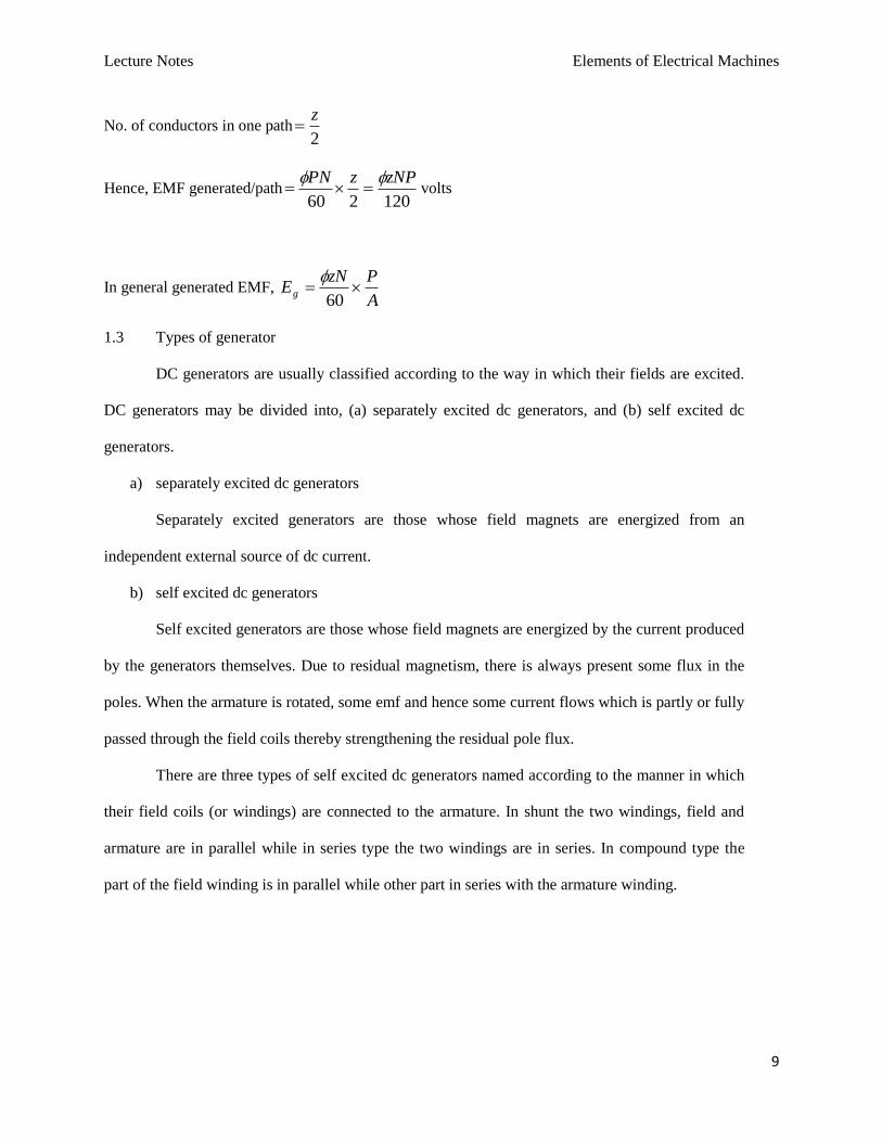
1.3 Types of generator
DC generators are usually classified according to the way in which their fields are excited.
DC generators may be divided into, (a) separately excited dc generators, and (b) self excited dc
generators.
a) separately excited dc generators
Separately excited generators are those whose field magnets are energized from an
independent external source of dc current.
b) self excited dc generators
Self excited generators are those whose field magnets are energized by the current produced
by the generators themselves. Due to residual magnetism, there is always present some flux in the
poles. When the armature is rotated, some emf and hence some current flows which is partly or fully
passed through the field coils thereby strengthening the residual pole flux.
There are three types of self excited dc generators named according to the manner in which
their field coils (or windings) are connected to the armature. In shunt the two windings, field and
armature are in parallel while in series type the two windings are in series. In compound type the
part of the field winding is in parallel while other part in series with the armature winding.
Lecture Notes Elements of Electrical Machines
10
Fig.1.3 DC generators classification
Lecture Notes Elements of Electrical Machines
11
D.C. Motor
An electric motor is a machine which converts electrical energy into mechanical energy.
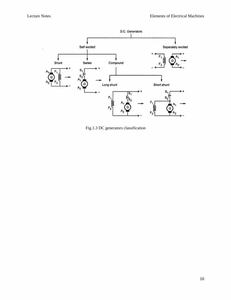
2.1 Principle of operation
It is based on the principle that when a current-carrying conductor is placed in a magnetic field, it
experiences a mechanical force whose direction is given by Fleming's Left-hand rule and whose
magnitude is given by
Force, F = B I l newton
Where B is the magnetic field in weber/m2. I is the current in amperes and l is the length of the coil in
meter.
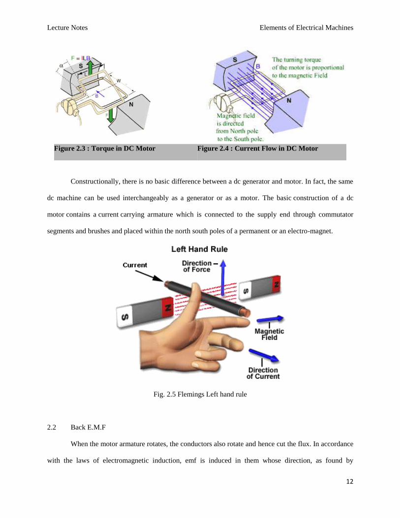
Fleming’s left hand rule says that if we extend the index finger, middle finger and thumb of our
left hand in such a way that the current carrying conductor is placed in a magnetic field (represented by
the index finger) is perpendicular to the direction of current (represented by the middle finger), then the
conductor experiences a force in the direction (represented by the thumb) mutually perpendicular to both
the direction of field and the current in the conductor.
Figure 2.1: Force in DC Motor Figure 2.2 : Magnetic Field in DC Motor
Lecture Notes Elements of Electrical Machines
12
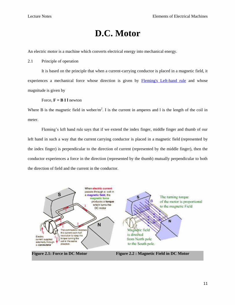
Figure 2.3 : Torque in DC Motor Figure 2.4 : Current Flow in DC Motor
Constructionally, there is no basic difference between a dc generator and motor. In fact, the same
dc machine can be used interchangeably as a generator or as a motor. The basic construction of a dc
motor contains a current carrying armature which is connected to the supply end through commutator
segments and brushes and placed within the north south poles of a permanent or an electro-magnet.
Fig. 2.5 Flemings Left hand rule
2.2 Back E.M.F
When the motor armature rotates, the conductors also rotate and hence cut the flux. In accordance
with the laws of electromagnetic induction, emf is induced in them whose direction, as found by
Lecture Notes Elements of Electrical Machines
13
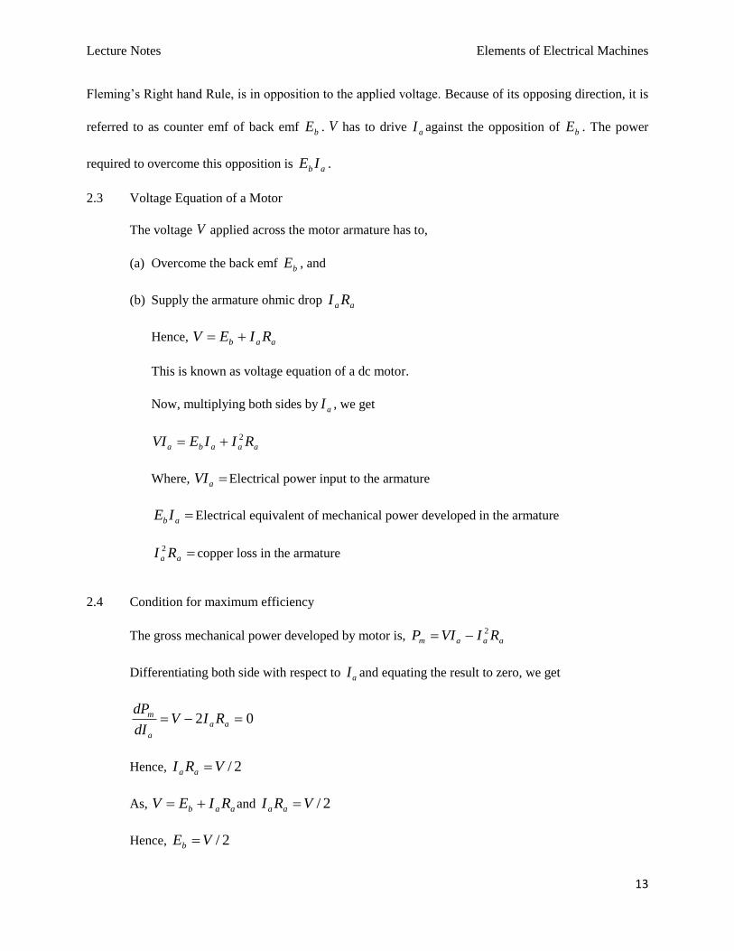
Fleming’s Right hand Rule, is in opposition to the applied voltage. Because of its opposing direction, it is
referred to as counter emf of back emf bE . V has to drive aI against the opposition of bE . The power
required to overcome this opposition is ab IE .
2.3 Voltage Equation of a Motor
The voltage V applied across the motor armature has to,
(a) Overcome the back emf bE , and
(b) Supply the armature ohmic drop aa RI
Hence, aab RIEV
This is known as voltage equation of a dc motor.
Now, multiplying both sides by aI , we get
aaaba RIIEVI 2
Where, aVI Electrical power input to the armature
abIE Electrical equivalent of mechanical power developed in the armature
aa RI 2copper loss in the armature
2.4 Condition for maximum efficiency
The gross mechanical power developed by motor is, aaam RIVIP 2
Differentiating both side with respect to aI and equating the result to zero, we get
02 aa
a
m RIVdI
dP
Hence, 2/VRI aa
As, aab RIEV and 2/VRI aa
Hence, 2/VEb
Lecture Notes Elements of Electrical Machines
14
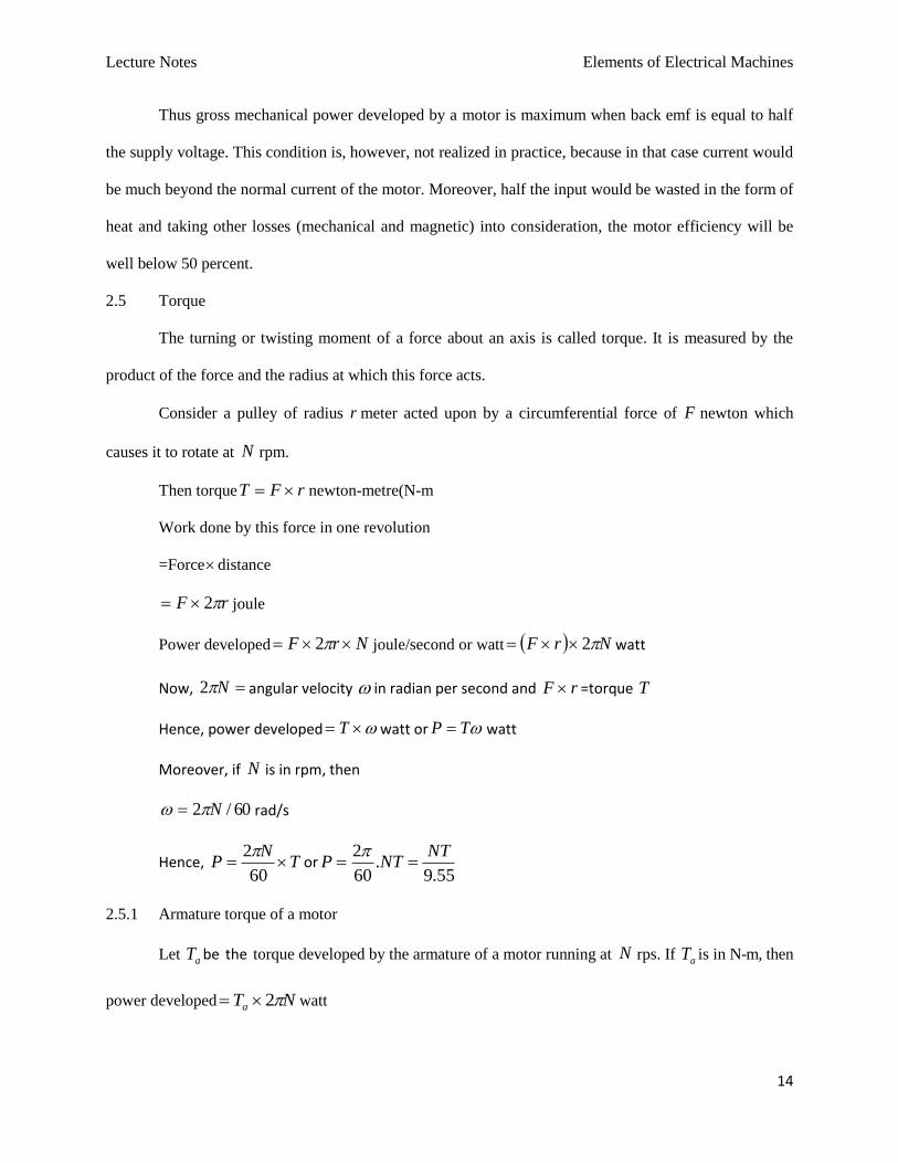
Thus gross mechanical power developed by a motor is maximum when back emf is equal to half
the supply voltage. This condition is, however, not realized in practice, because in that case current would
be much beyond the normal current of the motor. Moreover, half the input would be wasted in the form of
heat and taking other losses (mechanical and magnetic) into consideration, the motor efficiency will be
well below 50 percent.
2.5 Torque
The turning or twisting moment of a force about an axis is called torque. It is measured by the
product of the force and the radius at which this force acts.
Consider a pulley of radius r meter acted upon by a circumferential force of F newton which
causes it to rotate at N rpm.
Then torque rFT newton-metre(N-m
Work done by this force in one revolution
=Forcedistance
rF 2 joule
Power developed NrF 2 joule/second or watt NrF 2 watt
Now, N2 angular velocity in radian per second and rF =torque T
Hence, power developed T watt or TP watt
Moreover, if N is in rpm, then
60/2 N rad/s
Hence, TN
P 60
2or
55.9.
60
2 NTNTP
2.5.1 Armature torque of a motor
Let aT be the torque developed by the armature of a motor running at N rps. If aT is in N-m, then
power developed NTa 2 watt
Lecture Notes Elements of Electrical Machines
15
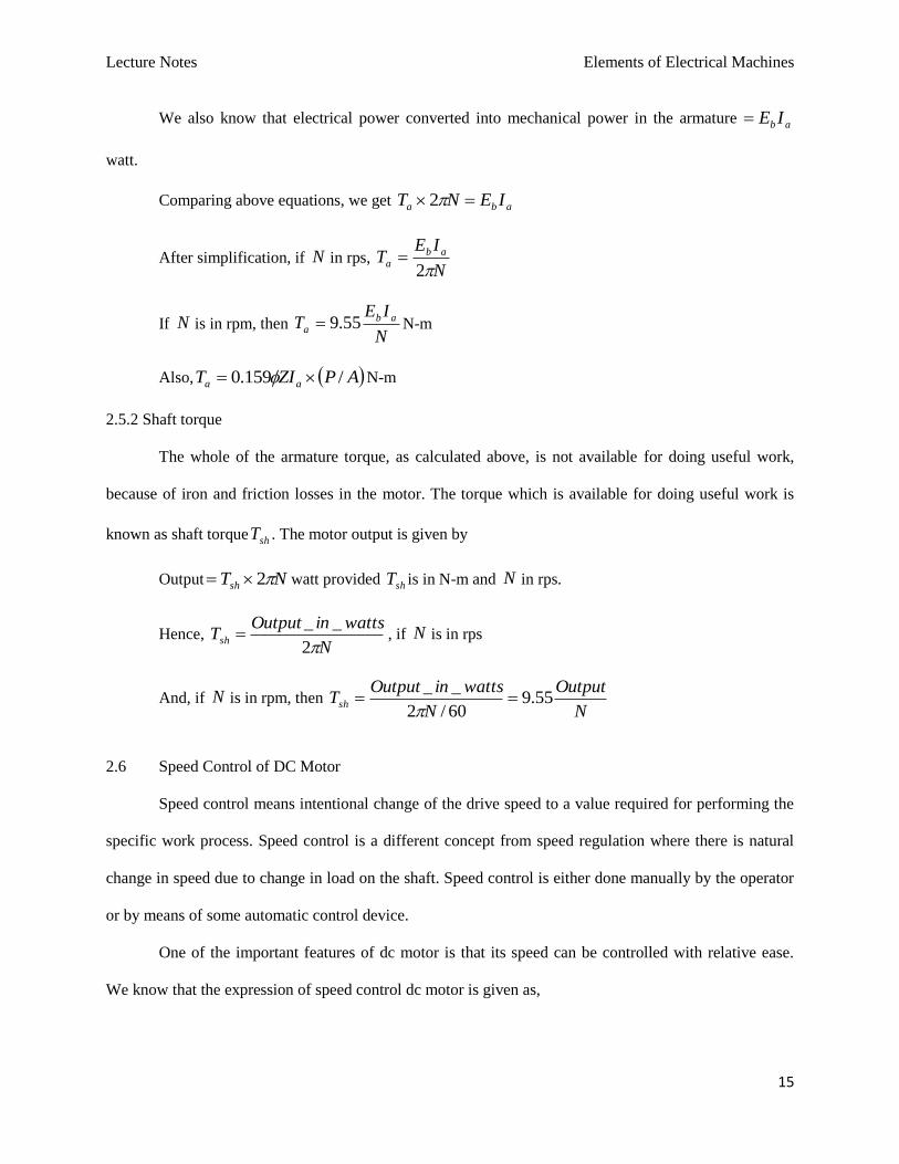
We also know that electrical power converted into mechanical power in the armature ab IE
watt.
Comparing above equations, we get aba IENT 2
After simplification, if N in rps, N
IET ab
a2
If N is in rpm, then N
IET ab
a 55.9 N-m
Also, APZIT aa /159.0 N-m
2.5.2 Shaft torque
The whole of the armature torque, as calculated above, is not available for doing useful work,
because of iron and friction losses in the motor. The torque which is available for doing useful work is
known as shaft torque shT . The motor output is given by
Output NTsh 2 watt provided shT is in N-m and N in rps.
Hence, N
wattsinOutputTsh
2
__ , if N is in rps
And, if N is in rpm, then N
Output
N
wattsinOutputTsh 55.9
60/2
__
2.6 Speed Control of DC Motor
Speed control means intentional change of the drive speed to a value required for performing the
specific work process. Speed control is a different concept from speed regulation where there is natural
change in speed due to change in load on the shaft. Speed control is either done manually by the operator
or by means of some automatic control device.
One of the important features of dc motor is that its speed can be controlled with relative ease.
We know that the expression of speed control dc motor is given as,
Lecture Notes Elements of Electrical Machines
16
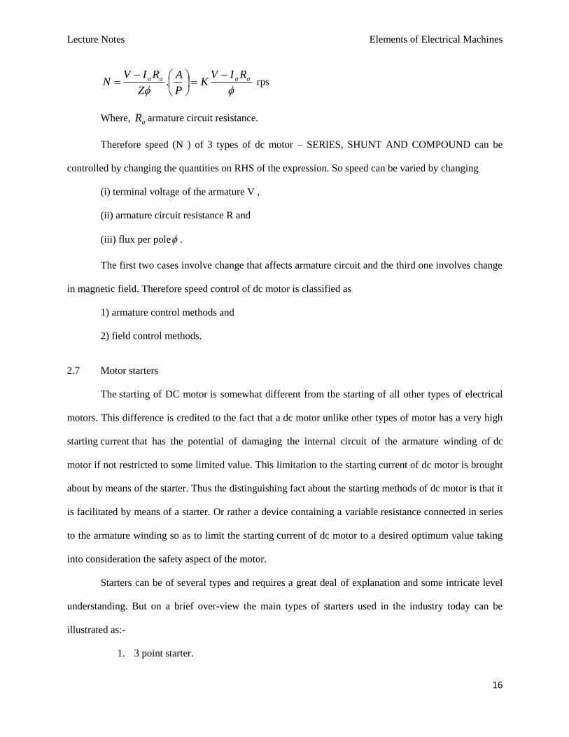
aaaa RIV
KP
A
Z
RIVN
. rps
Where, aR armature circuit resistance.
Therefore speed (N ) of 3 types of dc motor – SERIES, SHUNT AND COMPOUND can be
controlled by changing the quantities on RHS of the expression. So speed can be varied by changing
(i) terminal voltage of the armature V ,
(ii) armature circuit resistance R and
(iii) flux per pole .
The first two cases involve change that affects armature circuit and the third one involves change
in magnetic field. Therefore speed control of dc motor is classified as
1) armature control methods and
2) field control methods.
2.7 Motor starters
The starting of DC motor is somewhat different from the starting of all other types of electrical
motors. This difference is credited to the fact that a dc motor unlike other types of motor has a very high
starting current that has the potential of damaging the internal circuit of the armature winding of dc
motor if not restricted to some limited value. This limitation to the starting current of dc motor is brought
about by means of the starter. Thus the distinguishing fact about the starting methods of dc motor is that it
is facilitated by means of a starter. Or rather a device containing a variable resistance connected in series
to the armature winding so as to limit the starting current of dc motor to a desired optimum value taking
into consideration the safety aspect of the motor.
Starters can be of several types and requires a great deal of explanation and some intricate level
understanding. But on a brief over-view the main types of starters used in the industry today can be
illustrated as:-
1. 3 point starter.
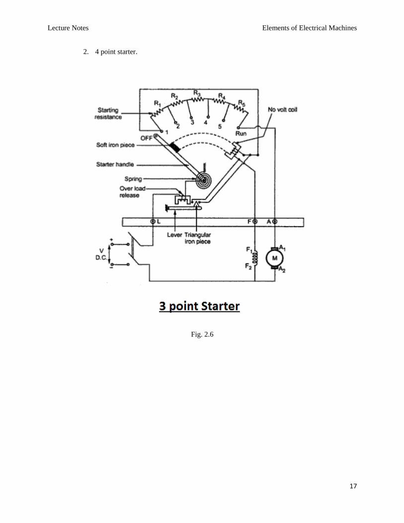
Lecture Notes Elements of Electrical Machines
17
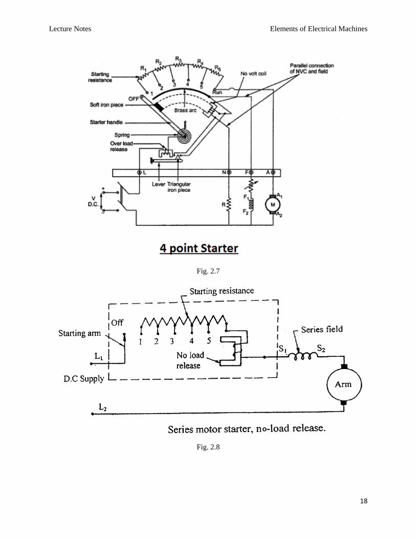
2. 4 point starter.
Fig. 2.6
Lecture Notes Elements of Electrical Machines
18
Fig. 2.7
Fig. 2.8
Lecture Notes Elements of Electrical Machines
19
Single phase Transformer
3.1 Principle of operation and construction
A transformer is a static or stationary piece of apparatus by means of which electric power in one
circuit is transformed into electric power of the same frequency in another circuit. Although transformers
have no moving parts, they are essential to electromechanical energy conversion. They make it possible to
increase or decrease the voltage so that power can be transmitted at a voltage level that results in low
costs, and can be distributed and used safely. In addition, they can provide matching of impedances, and
regulate the flow of power (real or reactive) in a network.
The physical basis of a transformer is mutual induction between two circuits linked by a common
magnetic field.
In its simplest form, it consists of two inductive coils which are electrically separated but
magnetically linked through a path of low reluctance. The two coils posses high mutual
inductance.
If one coil is connected to a source of alternating voltage, an alternating flux is set up in the
laminated core, most of which is linked with the other coil in which it produces mutually induced
emf.
Constructionally, the transformers are of two general types, distinguished from each other merely
by the manner in which the primary and secondary coils are placed around the laminated core.
a) Core type
b) Shell type
In the so-called core type transformer, the windings surround a considerable part of the core
whereas in shell-type transformer, the core surrounds considerable portions of the winding.
Lecture Notes Elements of Electrical Machines
20
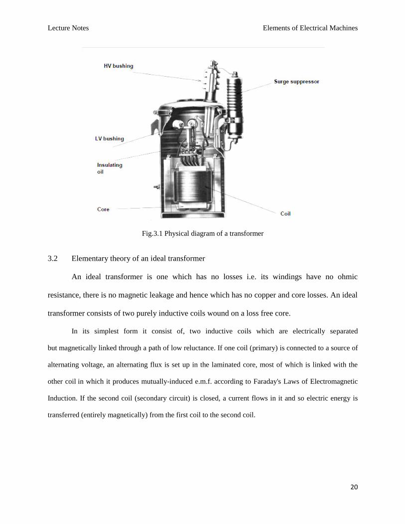
Fig.3.1 Physical diagram of a transformer
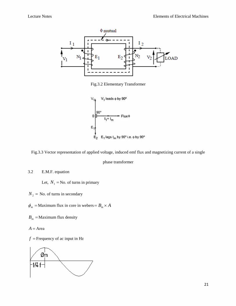
3.2 Elementary theory of an ideal transformer
An ideal transformer is one which has no losses i.e. its windings have no ohmic
resistance, there is no magnetic leakage and hence which has no copper and core losses. An ideal
transformer consists of two purely inductive coils wound on a loss free core.
In its simplest form it consist of, two inductive coils which are electrically separated
but magnetically linked through a path of low reluctance. If one coil (primary) is connected to a source of
alternating voltage, an alternating flux is set up in the laminated core, most of which is linked with the
other coil in which it produces mutually-induced e.m.f. according to Faraday's Laws of Electromagnetic
Induction. If the second coil (secondary circuit) is closed, a current flows in it and so electric energy is
transferred (entirely magnetically) from the first coil to the second coil.
Lecture Notes Elements of Electrical Machines
21
Fig.3.2 Elementary Transformer
Fig.3.3 Vector representation of applied voltage, induced emf flux and magnetizing current of a single
phase transformer
3.2 E.M.F. equation
Let, 1N No. of turns in primary
2N No. of turns in secondary
m Maximum flux in core in webers ABm
mB Maximum flux density
A Area
f Frequency of ac input in Hz
Lecture Notes Elements of Electrical Machines
22
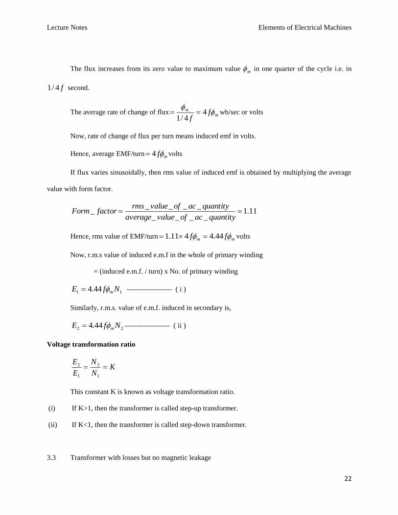
The flux increases from its zero value to maximum value m in one quarter of the cycle i.e. in
f4/1 second.
The average rate of change of fluxm
m ff
44/1
wb/sec or volts
Now, rate of change of flux per turn means induced emf in volts.
Hence, average EMF/turn mf4 volts
If flux varies sinusoidally, then rms value of induced emf is obtained by multiplying the average
value with form factor.
11.1____
_____
quantityacofvalueaverage
quantityacofvaluermsfactorForm
Hence, rms value of EMF/turn mm ff 44.4411.1 volts
Now, r.m.s value of induced e.m.f in the whole of primary winding
= (induced e.m.f. / turn) x No. of primary winding
11 44.4 NfE m ------------------- ( i )
Similarly, r.m.s. value of e.m.f. induced in secondary is,
22 44.4 NfE m ------------------- ( ii )
Voltage transformation ratio
KN
N
E
E
1
2
1
2
This constant K is known as voltage transformation ratio.
(i) If K>1, then the transformer is called step-up transformer.
(ii) If K<1, then the transformer is called step-down transformer.
3.3 Transformer with losses but no magnetic leakage
Lecture Notes Elements of Electrical Machines
23
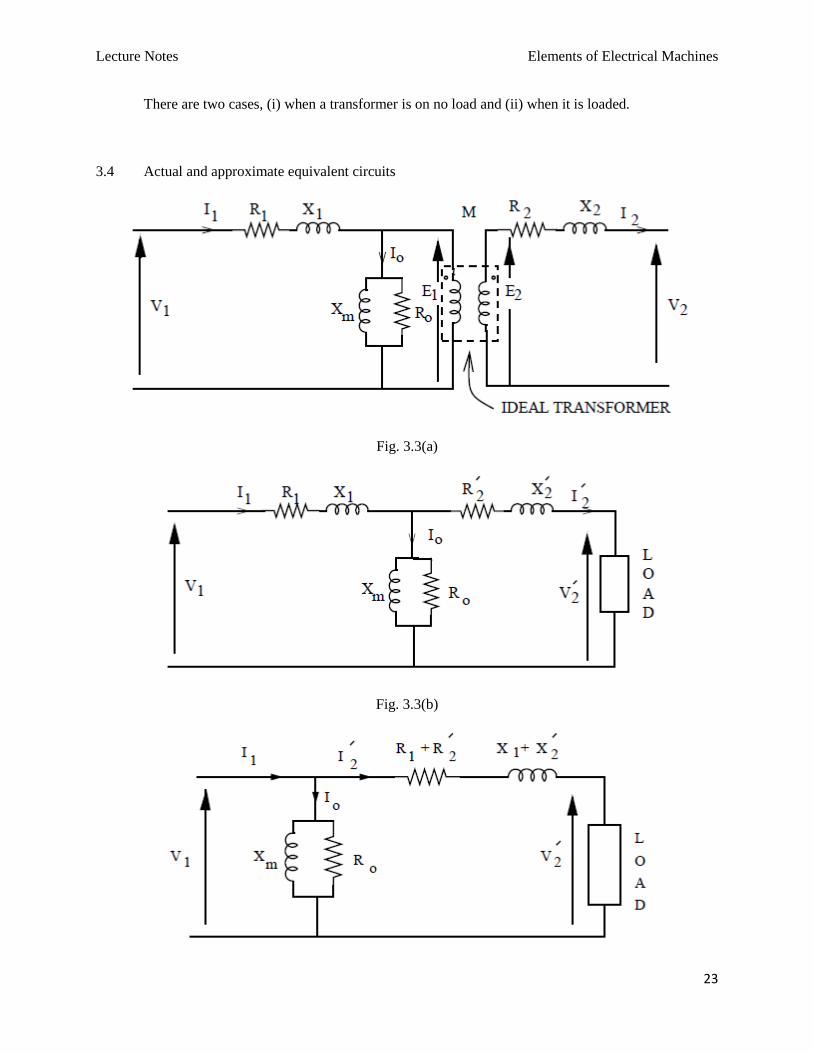
There are two cases, (i) when a transformer is on no load and (ii) when it is loaded.
3.4 Actual and approximate equivalent circuits
Fig. 3.3(a)
Fig. 3.3(b)
Lecture Notes Elements of Electrical Machines
24
Fig.3.4 Approximate equivalent circuit of transformer
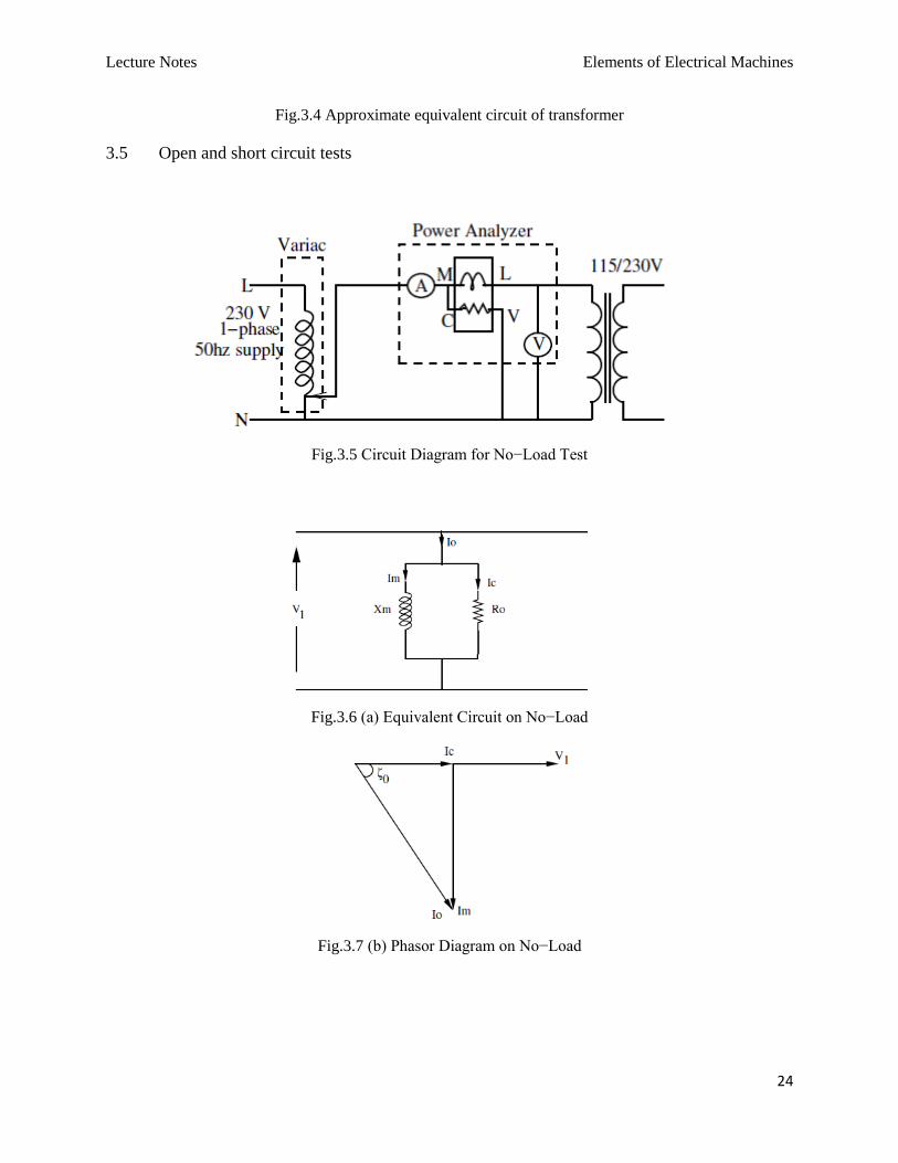
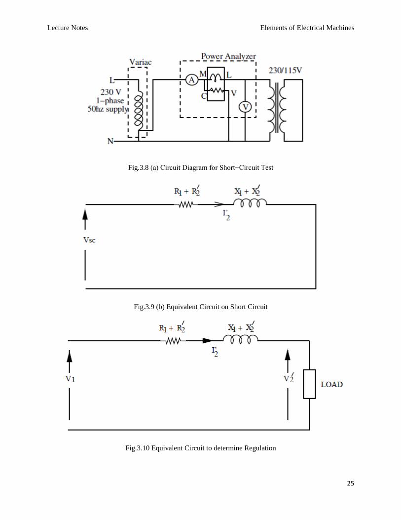
3.5 Open and short circuit tests
Fig.3.5 Circuit Diagram for No−Load Test
Fig.3.6 (a) Equivalent Circuit on No−Load
Fig.3.7 (b) Phasor Diagram on No−Load
Lecture Notes Elements of Electrical Machines
25
Fig.3.8 (a) Circuit Diagram for Short−Circuit Test
Fig.3.9 (b) Equivalent Circuit on Short Circuit
Fig.3.10 Equivalent Circuit to determine Regulation
Lecture Notes Elements of Electrical Machines
26
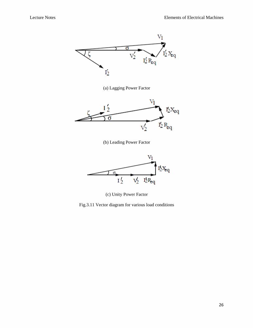
(a) Lagging Power Factor
(b) Leading Power Factor
(c) Unity Power Factor
Fig.3.11 Vector diagram for various load conditions
Lecture Notes Elements of Electrical Machines
27
Three Phase Transformer
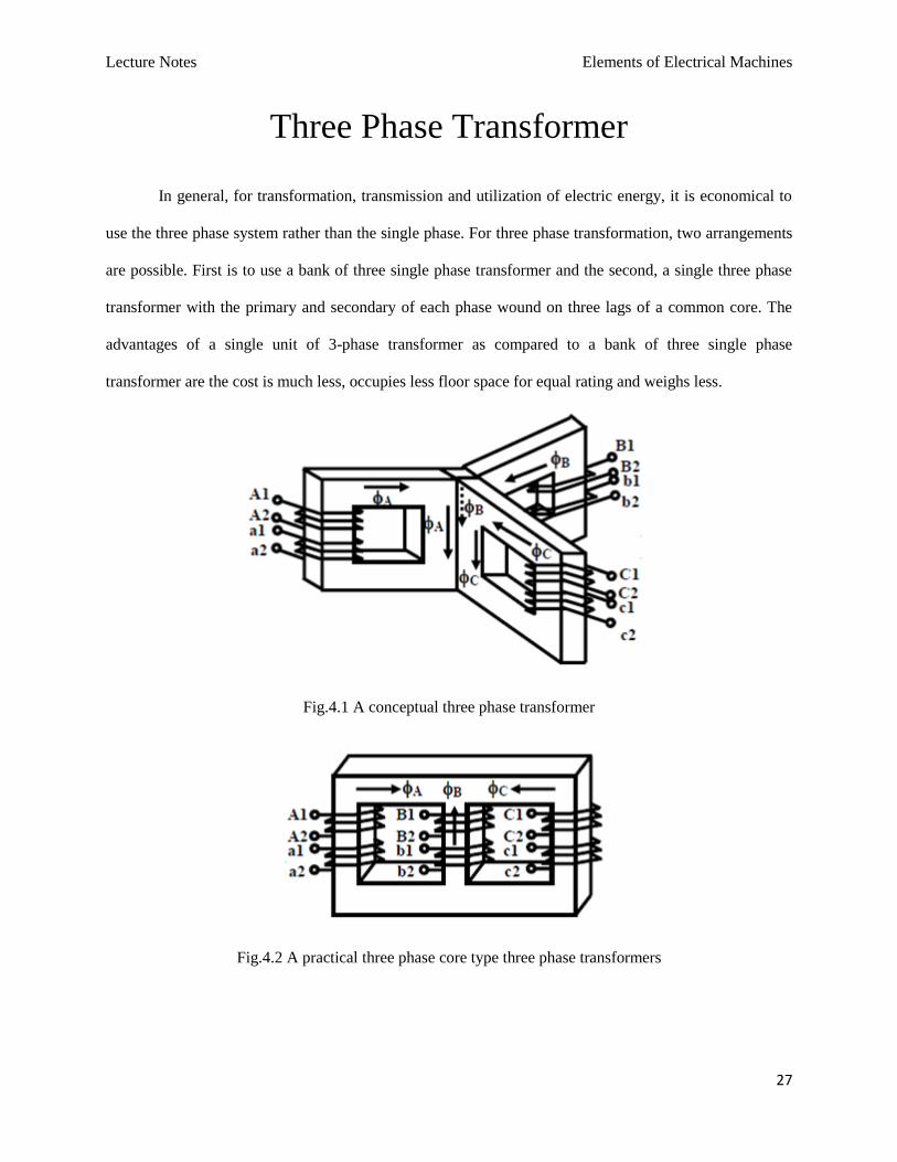
In general, for transformation, transmission and utilization of electric energy, it is economical to
use the three phase system rather than the single phase. For three phase transformation, two arrangements
are possible. First is to use a bank of three single phase transformer and the second, a single three phase
transformer with the primary and secondary of each phase wound on three lags of a common core. The
advantages of a single unit of 3-phase transformer as compared to a bank of three single phase
transformer are the cost is much less, occupies less floor space for equal rating and weighs less.
Fig.4.1 A conceptual three phase transformer
Fig.4.2 A practical three phase core type three phase transformers
Lecture Notes Elements of Electrical Machines
28
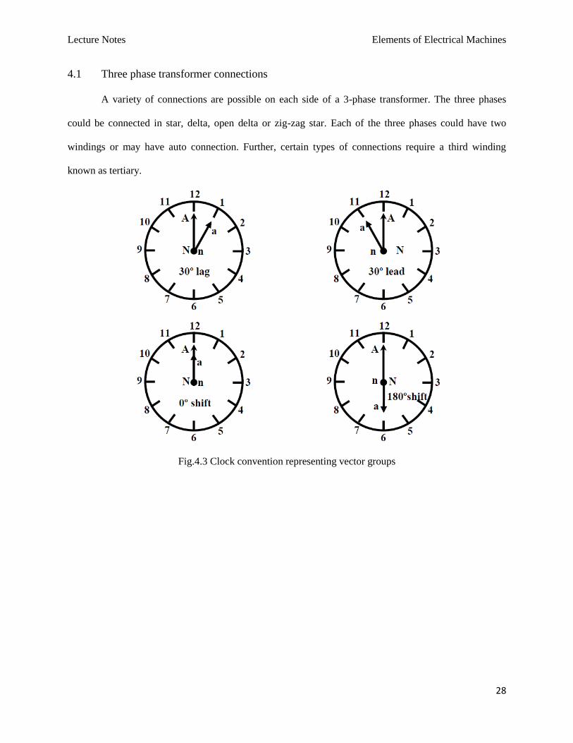
4.1 Three phase transformer connections
A variety of connections are possible on each side of a 3-phase transformer. The three phases
could be connected in star, delta, open delta or zig-zag star. Each of the three phases could have two
windings or may have auto connection. Further, certain types of connections require a third winding
known as tertiary.
Fig.4.3 Clock convention representing vector groups
Lecture Notes Elements of Electrical Machines
29
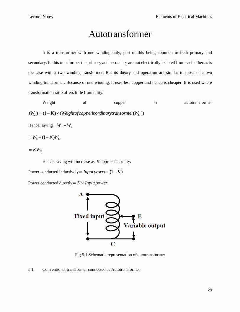
Autotransformer
It is a transformer with one winding only, part of this being common to both primary and
secondary. In this transformer the primary and secondary are not electrically isolated from each other as is
the case with a two winding transformer. But its theory and operation are similar to those of a two
winding transformer. Because of one winding, it uses less copper and hence is cheaper. It is used where
transformation ratio offers little from unity.
Weight of copper in autotransformer
))(()1()( Oa WtransormerordinaryincopperWeightofKW
Hence, saving aWW 0
OWKW )1(0
OKW
Hence, saving will increase as K approaches unity.
Power conducted inductively )1( KpowerInput
Power conducted directly powerInputK
Fig.5.1 Schematic representation of autotransformer
5.1 Conventional transformer connected as Autotransformer
Lecture Notes Elements of Electrical Machines
30
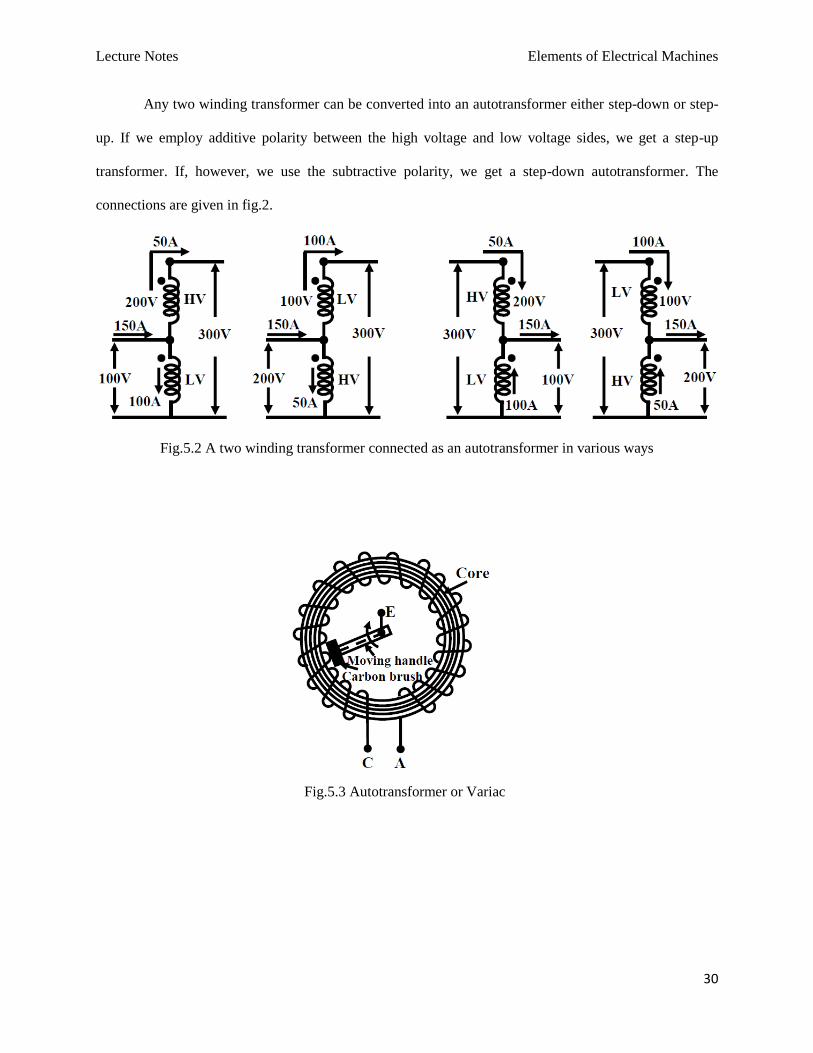
Any two winding transformer can be converted into an autotransformer either step-down or step-
up. If we employ additive polarity between the high voltage and low voltage sides, we get a step-up
transformer. If, however, we use the subtractive polarity, we get a step-down autotransformer. The
connections are given in fig.2.
Fig.5.2 A two winding transformer connected as an autotransformer in various ways
Fig.5.3 Autotransformer or Variac
Lecture Notes Elements of Electrical Machines
31
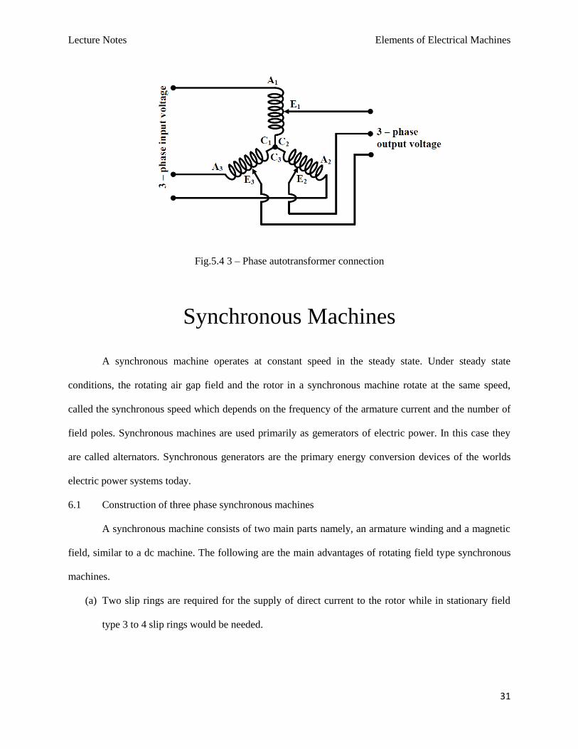
Fig.5.4 3 – Phase autotransformer connection
Synchronous Machines
A synchronous machine operates at constant speed in the steady state. Under steady state
conditions, the rotating air gap field and the rotor in a synchronous machine rotate at the same speed,
called the synchronous speed which depends on the frequency of the armature current and the number of
field poles. Synchronous machines are used primarily as gemerators of electric power. In this case they
are called alternators. Synchronous generators are the primary energy conversion devices of the worlds
electric power systems today.
6.1 Construction of three phase synchronous machines
A synchronous machine consists of two main parts namely, an armature winding and a magnetic
field, similar to a dc machine. The following are the main advantages of rotating field type synchronous
machines.
(a) Two slip rings are required for the supply of direct current to the rotor while in stationary field
type 3 to 4 slip rings would be needed.
Lecture Notes Elements of Electrical Machines
32
(b) The power used in exciting the field system may be only about two percent of the ac output of the
machine and that too is supplied at low voltage, thus it is easier and economical to design slip
rings to carry this smaller power for the rotating field.
(c) The voltage generated in the armature is much higher and therefore greater insulation is required
for the armature winding. Thus it is much easier to insulate the high voltage winding when it is
mounted on a stationary structure.
(d) Note that by the use of stationary armature this high voltage insulation is not subjected to
mechanical stress due to centrifugal forces. The end conductors of the armature winding can be
braced securely in position thereby making it fit to withstand the large forces by sudden short
circuit.
(e) The main connecting cables can be connected directly with the armature winding. With rotating
armature, the current would have to be calculated by means of slip rings and with high voltage
and large power, such collection, would pose serious problems.
(f) Rotating field is comparatively light and can be constructed for high speed operation.
(g) Cooling systems are comparatively easier.
6.1.1 Stator
The stator of a three phase synchronous machine consists of a stator frame, a slotted stator, which
provides a low reluctance path for the magnetic flux. It has a distributed winding embedded in the slots
similar to that of three phase induction machine.
6.1.2 Rotor
The rotor has a winding called the field winding, which carries direct current. The field winding
on the rotating frame is normally fed from an external dc source through slip rings and bruses. Two types
of rotors are used in synchronous machines, the cylindrical rotor and a salient pole rotor. Depending on
the type of rotor used synchronous machines are broadly divided into two groups as follows:
High speed machines with cylindrical (non- salient pole) rotors
Lecture Notes Elements of Electrical Machines
33
Low speed machines with salient pole rotors
The cylindrical rotor has one distributed winding and an essentially uniform air gap. These rotors
are used in large generators with two or sometimes four poles and are usually driven by steam turbines.
The rotors are long and have a small diameter. The features are,
They have small diameters and very long axial length.
Dynamic balancing is better.
Operation is quieter and windage losses are less.
The speed is 1000 to 3000 rpm.
Used with steam turbines and steam engines.
The rotors of salient pole machines have concentrated winding on the poles and a non-uniform air
gap. Salient pole generators have a large number of poles, sometimes as many as 50, and operate at lower
speed. The alternators in hydroelectric power stations are of the salient pole type and are driven by water
turbines. The rotors are shorter in length but have a large diameter. The speed is 120 to 400 rpm.
6.2 Equation of induced E.M.F.
Let, flux per pole in weber
z total number of armature conductors or coil sides in series/phase T2
T no. of turns or coils per phase
P no. of generator poles
f frequence of induced emf in Hz
N rotor speed in revolutions per minute (rpm)
dK distribution factor 2/sin
2/sin
m
m
cK or PK pitch or coil span factor2
cos
fK form factor
Lecture Notes Elements of Electrical Machines
34
In one revolution of the rotor (i.e. in N/60 seconds) each conductor is cut by a flux of P weber.
Hence, Pd and N
dt60
seconds
Hence, average emf induced/conductor60
NP
dt
d volts, 1n
Now, we know that 120
PNf or
P
fN
120
Substituting this value of N above, we get
Average emf induced/conductor
fP
fP2
120
60 volts
If there are z no. of conductors in series/phase, then average emf/phase zf2 volts Tf4 volts
Hence,RMS value of emf/phase Tf44.4 volts
This would have been the actual value of the induced voltage if all the coils in a phase were,
(i)full pitched, and (ii)concentrated or bunched in one slot. But this is not being so, the actually available
voltage is reduced in the ration of these two factors.
Hence, actually available voltage/phase TfKK dc 44.4 volts
TfKKK dcf 4 volts
If the alternator is star connected then the line voltage is 3 times the phase voltage.
6.2.1 Short-Pitch Winding
Advantages
Copper in end connection can be saved.
Harmonics are reduced
Iron losses will be reduced
Efficiency will be increased
Generated voltage waveform will be improved is more sinusoidal.

Lecture Notes Elements of Electrical Machines
35
Disadvantages:-
The magnitude of the induced voltage will be reduced
6.2.2 Distributed Winding
Advantages
The generated voltage waveform will be improved, is more sinusoidal.
Disadvantage
The magnitude of induced voltage will be reduced
6.3 Synchronous motor
A synchronous motor runs under steady state condition at a fixed speed called the synchronous speed.
The synchronous speed depends only upon the frequency of the applied voltage and the number of poles
in the machine. The speed of the synchronous motor is independent of the load as long as the load is
within the capability of the motor. If the load torque exceeds the maximum torque that can be developed
by the motor, the motor simply comes to rest.
6.4 Principle of operation of synchronous motor
Synchronous motor is a doubly excited machine i.e two electrical inputs are provided to it. It’s
stator winding which consists of a 3 phase winding is provided with 3 phase supply and rotor is provided
with DC supply. The 3 phase stator winding carrying 3 phase currents produces 3 phase rotating magnetic
flux. The rotor carrying DC supply also produces a constant flux. Considering the frequency to be 50 Hz,
from the above relation we can see that the 3 phase rotating flux rotates about 3000 revolution in 1 min or
50 revolutions in 1 sec. At a particular instant rotor and stator poles might be of same polarity (N-N or S-
S) causing repulsive force on rotor and the very next second it will be N-S causing attractive force. But
due to inertia of the rotor, it is unable to rotate in any direction due to attractive or repulsive force and
remain in standstill condition. Hence it is not self starting.
Lecture Notes Elements of Electrical Machines
36
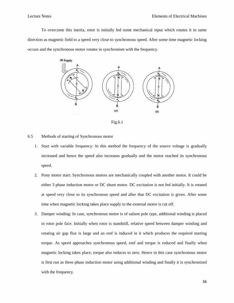
To overcome this inertia, rotor is initially fed some mechanical input which rotates it in same
direction as magnetic field to a speed very close to synchronous speed. After some time magnetic locking
occurs and the synchronous motor rotates in synchronism with the frequency.
Fig.6.1
6.5 Methods of starting of Synchronous motor
1. Start with variable frequency: In this method the frequency of the source voltage is gradually
increased and hence the speed also increases gradually and the motor reached its synchronous
speed.
2. Pony motor start: Synchronous motors are mechanically coupled with another motor. It could be
either 3 phase induction motor or DC shunt motor. DC excitation is not fed initially. It is rotated
at speed very close to its synchronous speed and after that DC excitation is given. After some
time when magnetic locking takes place supply to the external motor is cut off.
3. Damper winding: In case, synchronous motor is of salient pole type, additional winding is placed
in rotor pole face. Initially when rotor is standstill, relative speed between damper winding and
rotating air gap flux is large and an emf is induced in it which produces the required starting
torque. As speed approaches synchronous speed, emf and torque is reduced and finally when
magnetic locking takes place, torque also reduces to zero. Hence in this case synchronous motor
is first run as three phase induction motor using additional winding and finally it is synchronized
with the frequency.
Lecture Notes Elements of Electrical Machines
37
6.6 Application of Synchronous Motor
1. Synchronous motor having no load connected to its shaft is used for power factor improvement.
Owing to its characteristics to behave at any electrical power factor, it is used in power system in
situations where static capacitors are expensive.
2. Synchronous motor finds application where operating speed is less (around 500 rpm) and high
power is required. For power requirement from 35 kW to 2500 KW, the size, weight and cost of
the corresponding three phase induction motor is very high. Hence these motors are preferably
used. Ex- Reciprocating pump, compressor, rolling mills etc.
Lecture Notes Elements of Electrical Machines
38
Three-phase Induction Motor
Induction Motors are the most commonly used motors in most of the applications. These are also
called as Asynchronous Motors, because an induction motor always runs at a speed lower than
synchronous speed. The induction motor is made up of the stator, or stationary windings, and the rotor.
The stator consists of a series of wire windings of very low resistance permanently attached to the motor
frame. When a voltage is applied to the stator winding terminals, a magnetic field is developed in the
windings. By the way the stator windings are arranged, the magnetic field appears to synchronously rotate
electrically around the inside of the motor housing.
Depending upon the input supply there are basically two types of induction motor,
(A) Single phase induction motor
Split phase induction motor
Capacitor start induction motor
Capacitor start capacitor run induction motor
Shaded pole induction motor
(B) Three phase induction motor
Squirrel cage induction motor
Slip ring (or phase wound) induction motor
Lecture Notes Elements of Electrical Machines
39
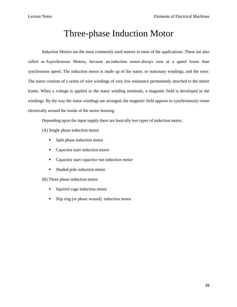
Fig.7.1
7.1 Construction
An induction motor has two main parts:
a) a stationary stator
It consisting of a steel frame that supports a hollow, cylindrical core, constructed from stacked
laminations having a number of evenly spaced slots, providing the space for the stator winding.
Lecture Notes Elements of Electrical Machines
40
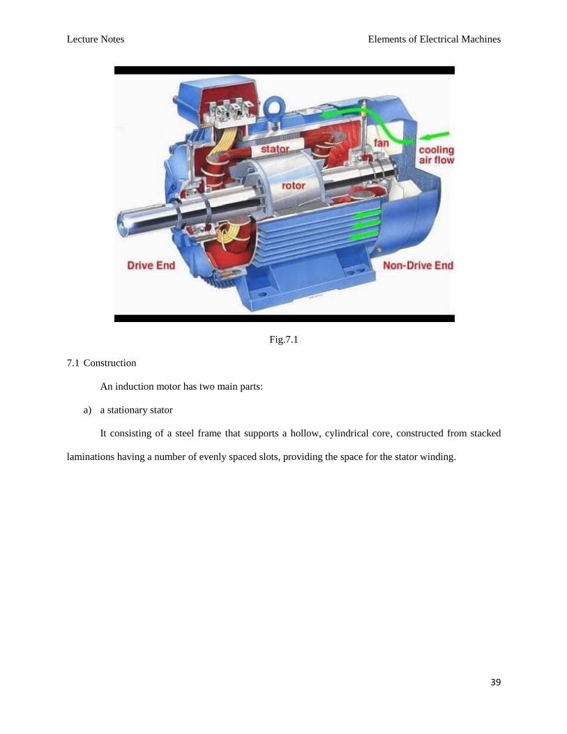
Fig.7.2 Stator
b) a revolving rotor
It composed of punched laminations, stacked to create a series of rotor slots, providing space for
the rotor winding. There are two types of rotors, squirrel cage type and slip ring type.
- Squirrel-cage: conducting bars laid into slots and shorted at both ends by shorting rings.
- Slip ring: complete set of three-phase windings exactly as the stator. Usually Y-
connected, the ends of the three rotor wires are connected to 3 slip rings on the rotor
shaft. In this way, the rotor circuit is accessible.
Lecture Notes Elements of Electrical Machines
41
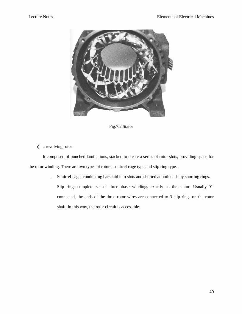
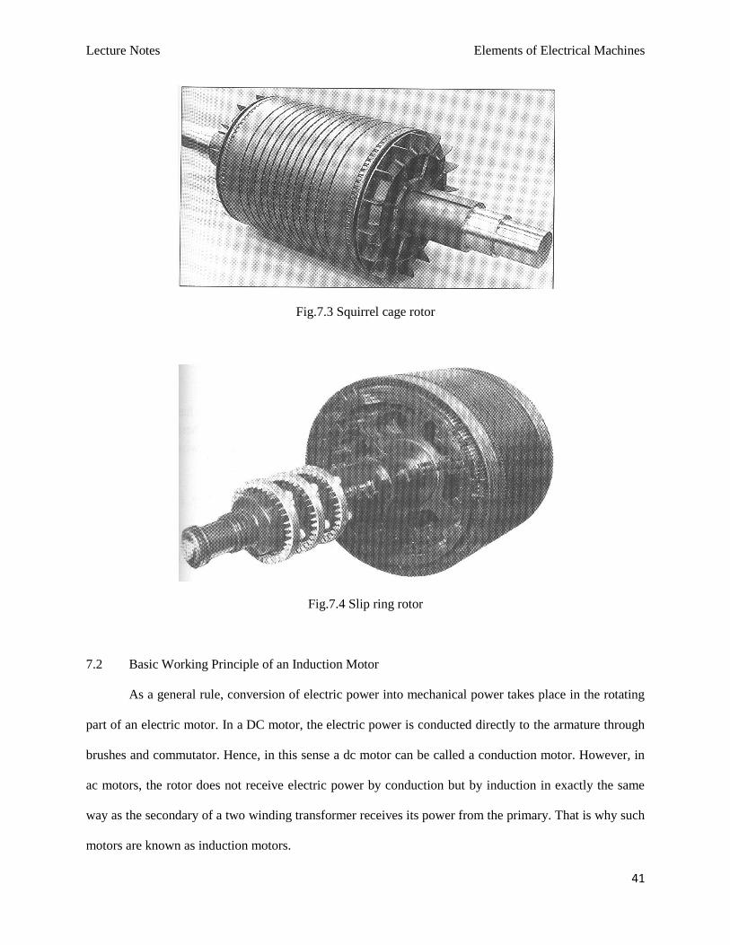
Fig.7.3 Squirrel cage rotor
Fig.7.4 Slip ring rotor
7.2 Basic Working Principle of an Induction Motor
As a general rule, conversion of electric power into mechanical power takes place in the rotating
part of an electric motor. In a DC motor, the electric power is conducted directly to the armature through
brushes and commutator. Hence, in this sense a dc motor can be called a conduction motor. However, in
ac motors, the rotor does not receive electric power by conduction but by induction in exactly the same
way as the secondary of a two winding transformer receives its power from the primary. That is why such
motors are known as induction motors.
Lecture Notes Elements of Electrical Machines
42
When the three phase stator windings are fed by a three phase supply then, a magnetic flux of
constant magnitude, but rotating at synchronous speed, is set up. The flux passes through the air gap,
sweeps past the rotor surface and so cuts the rotor conductors which, as yet, are stationary. Due to the
relative speed between the rotating flux and stationary conductors, an emf is induced in the later,
according to Faraday’s laws of electro-magnetic induction. The frequency of the induced emf is same as
the supply frequency. Its magnitude is proportional to the relative velocity between the flux and the
conductors and its direction is given by Fleming’s Right-hand rule. Since the rotor bars or conductors
form a closed circuit, rotor current is produced whose direction, as given by Lenz’s law, is such as to
oppose the very cause producing it. In this case, the cause which produces the rotor current is the relative
velocity between the rotating flux of the stator and the stationary rotor conductors. Hence, to reduce the
relative speed, the rotor starts running in the same direction as that of the flux and tries to catch up with
the rotating flux.
7.3 Slip
In practice, the motor never succeeds in catching up with the stator fiel. If it really did so, then
there would be no relative speed between the two, hence no rotor emf, no rotor current and so there will
be no torque to maintain rotation. That is why the rotor runs at a speed which is always less than yhe
speed of the stator field. The difference in speed depends upon the load on the motor.
The difference between the synchronous speed and the actual speed of the rotor is known as slip.
It is expressed as a percentage of the synchronous speed.
slip% 100
s
s
N
NNs
Sometimes, NN s is called the slip speed.
The rotor speed is sNN s 1
It may be noted here that revolving flux is rotating synchronously, relative to the stator (i.e.
stationary space) but at slip speed relative to the motor.
Lecture Notes Elements of Electrical Machines
43
7.4 Frequency of Rotor Current
When the rotor is stationary, the frequency of rotor current is same as the supply frequency. But
when the rotor starts revolving, then the frequency depends upon the relative speed or on slip speed. Let
at any slip-speed, the frequency of the rotor current be f ’. Then,
P
fNN s
120, also
P
fN s
120
After solving, we get, sN
NN
f
f
s
s
Then, rotor current have a frequency of
sff
7.5 Torque of an Induction motor
As we know, the torque aT is proportional to the product of armature current and flux per pole.
aa IT
In induction motor, 22 cos IT
Hence, 22 cosIKT
Where, 2I rotor current at standstill
2 angle between rotor emf and rotor current
K a constant
Denoting rotor emf at standstill by 2E , we have that
2E
Hence, 222 cos IET or 222 cosIET
Where, 1K is another constant.
7.5.1 Starting Torque
The torque developed by the motor at the instant of starting is called starting torque.
Lecture Notes Elements of Electrical Machines
44
Let, 2E rotor emf per phase at standstill
2R rotor resistance per phase
2X rotor reactance per phase at standstill
2
2
2
22 XRZ =rotor impedance per phase at standstill
Then, 2
2
2
2
2
2
22
XR
E
Z
EI
2
2
2
2
2
2
22cos
XR
R
Z
R
Starting torque, 2
2
2
2
2
2
2
2
2
2212221 cos
XR
R
XR
EEKIEKTst
Or, 2
2
2
2
2
2
21
XR
REKTst
Now, sN
K2
31
Hence, 2
2
2
2
2
2
2
2
3
XR
RE
NT
s
st
Where, sN synchronous speed in rps
7.5.2 Condition for maximum starting torque
If supply voltage V is constant, then the flux and hence, 2E both are constant
2
2
2
2
22
XR
RKTst
Differentiate both side with respect to 2R , we have
0
2.12
2
2
2
22
2
2
2
2
2
2
XR
RR
XRK
dR
dTst
Lecture Notes Elements of Electrical Machines
45
22 XR
The starting torque will be maximum if 22 XR .
7.5.3 Torque under running condition
Let, 2E rotor emf per phase at standstill
2R rotor resistance per phase
2f frequency of rotor current at standstill
Under running condition, 2sEEr
The frequency of the induced emf will likewise become
2sff r
Due to decrease in frequency of the rotor emf, the rotor reactance will also decrease.
Hence, 2sXX r
Where, rE and rX are emf and reactance under running conditions.
Now, the torque under running conditions
2cos rIT
Now, 2sEEr and
2
2
2
2
2
sXR
sE
Z
EI
r
rr
Also,
2
2
2
2
222cos
sXR
R
Z
R
r
2
2
2
2
2
2
2
2
2
22
sXR
R
sXR
sEETr
Or, 2
2
2
2
2
2
2
sXR
RsEKTst
Lecture Notes Elements of Electrical Machines
46
Where, K is a constant. Its value can be proved to be equal to sN2
3. Hence, in that case,
expression for torque becomes
2
2
2
2
2
2
2
2
3
sXR
RsE
NT
s
r
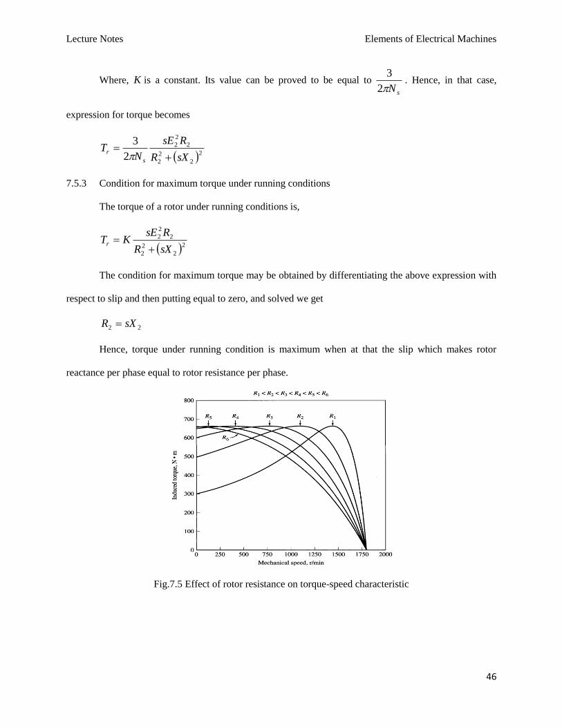
7.5.3 Condition for maximum torque under running conditions
The torque of a rotor under running conditions is,
2
2
2
2
2
2
2
sXR
RsEKTr
The condition for maximum torque may be obtained by differentiating the above expression with
respect to slip and then putting equal to zero, and solved we get
22 sXR
Hence, torque under running condition is maximum when at that the slip which makes rotor
reactance per phase equal to rotor resistance per phase.
Fig.7.5 Effect of rotor resistance on torque-speed characteristic
Lecture Notes Elements of Electrical Machines
47
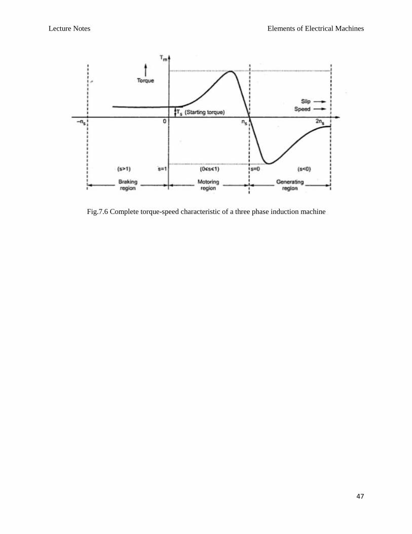
Fig.7.6 Complete torque-speed characteristic of a three phase induction machine
Lecture Notes Elements of Electrical Machines
48
SINGLE PHASE MOTORS
8.1 Single Phase Motors
Single phase motors are designed to operate from a single phase supply, are manufactured in a
large number of types to perform a wide variety of useful services in home, offices, factories, workshops
and in business establishments etc. Single phase motors may be classified as induction motors, repulsion
motors, ac series motor and unexcited synchronous motor.
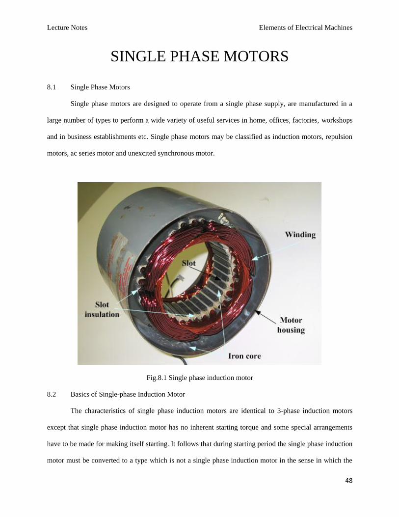
Fig.8.1 Single phase induction motor
8.2 Basics of Single-phase Induction Motor
The characteristics of single phase induction motors are identical to 3-phase induction motors
except that single phase induction motor has no inherent starting torque and some special arrangements
have to be made for making itself starting. It follows that during starting period the single phase induction
motor must be converted to a type which is not a single phase induction motor in the sense in which the
Lecture Notes Elements of Electrical Machines
49
term is ordinarily used and it becomes a true single phase induction motor when it is running and after the
speed and torque have been raised to a point beyond which the additional device may be dispensed with.
For these reasons, it is necessary to distinguish clearly between the starting period when the motor is not a
single phase induction motor and the normal running condition when it is a single phase induction motor.
The starting device adds to the cost of the motor and also requires more space. For the same output a 1-
phase motor is about 30% larger than a corresponding 3-phase motor.
The single phase induction motor in its simplest form is structurally the same as a poly-phase
induction motor having a squirrel cage rotor, the only difference is that the single phase induction motor
has single winding on the stator which produces mmf stationary in space but alternating in time, a poly-
phase stator winding carrying balanced currents produces mmf rotating in space around the air gap and
constant in time with respect to an observer moving with the mmf. The stator winding of the single phase
motor is disposed in slots around the inner periphery of a laminated ring similar to the 3-phase motor.
The single-phase induction motor operation can be described by two methods:
– Double revolving field theory; and
– Cross-field theory
8.3 Double-field Revolving Theory
This theory makes use of the idea that an alternating uni-axial quantity can be represented by two
oppositely rotating vectors of half magnitude. Accordingly, an alternating sinusoidal flux can be
represented by two revolving fluxes, each equal to half the value of the alternating flux and each rotating
synchronously PfNs /120 in opposite direction.
As shown in fig.8.2 (a), let the alternating flux have a maximum value of m . Its component
fluxes A and B will each be equal to 2/m revolving in anticlockwise and clockwise directions
respectively.
After some time, when A and B would have rotated through angle and , as in fig.8.2 (b),
the resultant flux would be
Lecture Notes Elements of Electrical Machines
50
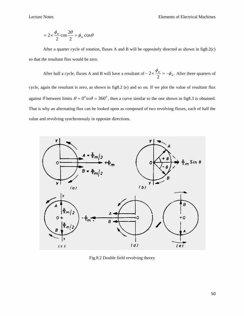
cos2
2cos
22 m
m
After a quarter cycle of rotation, fluxes A and B will be oppositely directed as shown in fig8.2(c)
so that the resultant flux would be zero.
After half a cycle, fluxes A and B will have a resultant of mm
22 . After three quarters of
cycle, again the resultant is zero, as shown in fig8.2 (e) and so on. If we plot the value of resultant flux
against between limits 00 to
0360 , then a curve similar to the one shown in fig8.3 is obtained.
That is why an alternating flux can be looked upon as composed of two revolving fluxes, each of half the
value and revolving synchronously in opposite directions.
Fig.8.2 Double field revolving theory
Lecture Notes Elements of Electrical Machines
51
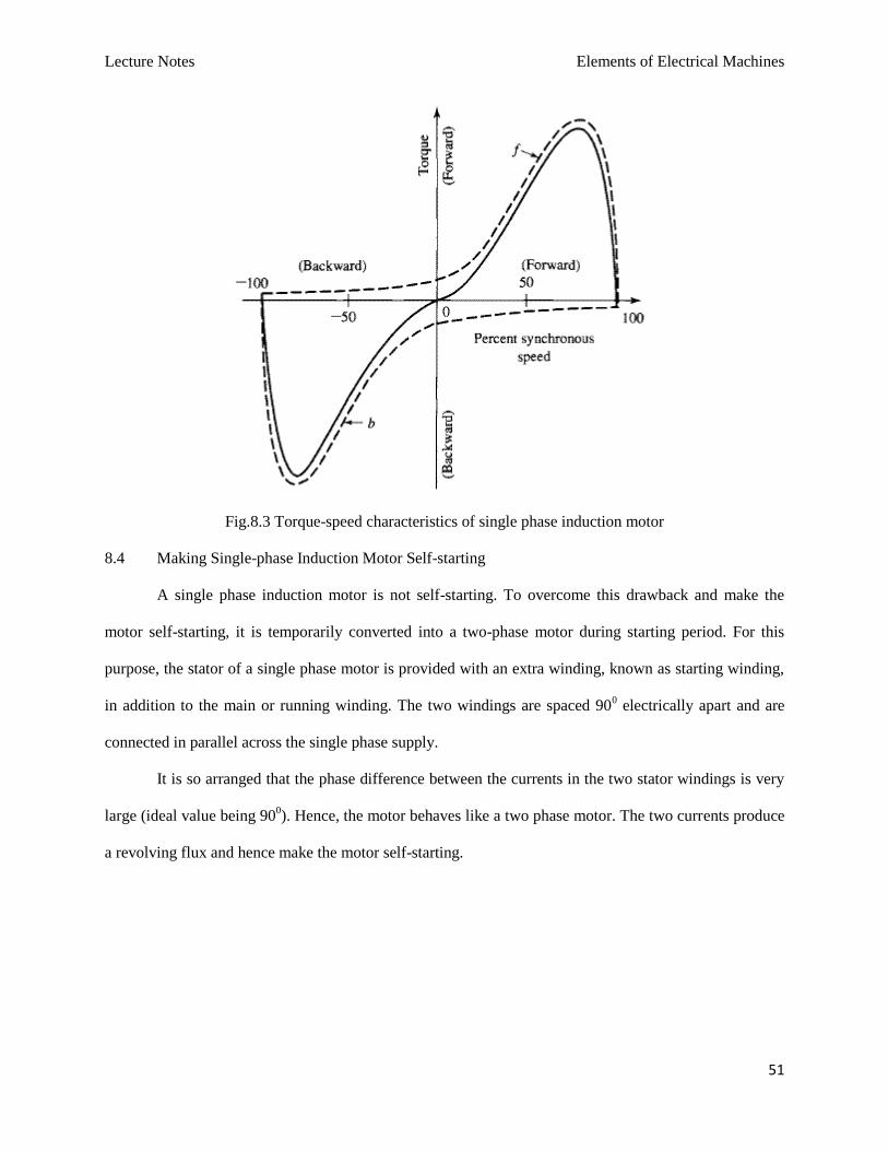
Fig.8.3 Torque-speed characteristics of single phase induction motor
8.4 Making Single-phase Induction Motor Self-starting
A single phase induction motor is not self-starting. To overcome this drawback and make the
motor self-starting, it is temporarily converted into a two-phase motor during starting period. For this
purpose, the stator of a single phase motor is provided with an extra winding, known as starting winding,
in addition to the main or running winding. The two windings are spaced 900 electrically apart and are
connected in parallel across the single phase supply.
It is so arranged that the phase difference between the currents in the two stator windings is very
large (ideal value being 900). Hence, the motor behaves like a two phase motor. The two currents produce
a revolving flux and hence make the motor self-starting.
Lecture Notes Elements of Electrical Machines
52
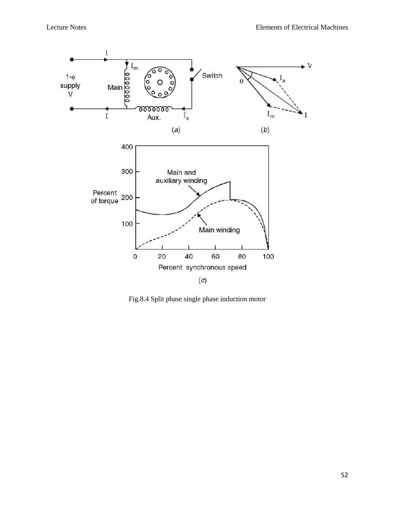
Fig.8.4 Split phase single phase induction motor
Lecture Notes Elements of Electrical Machines
53
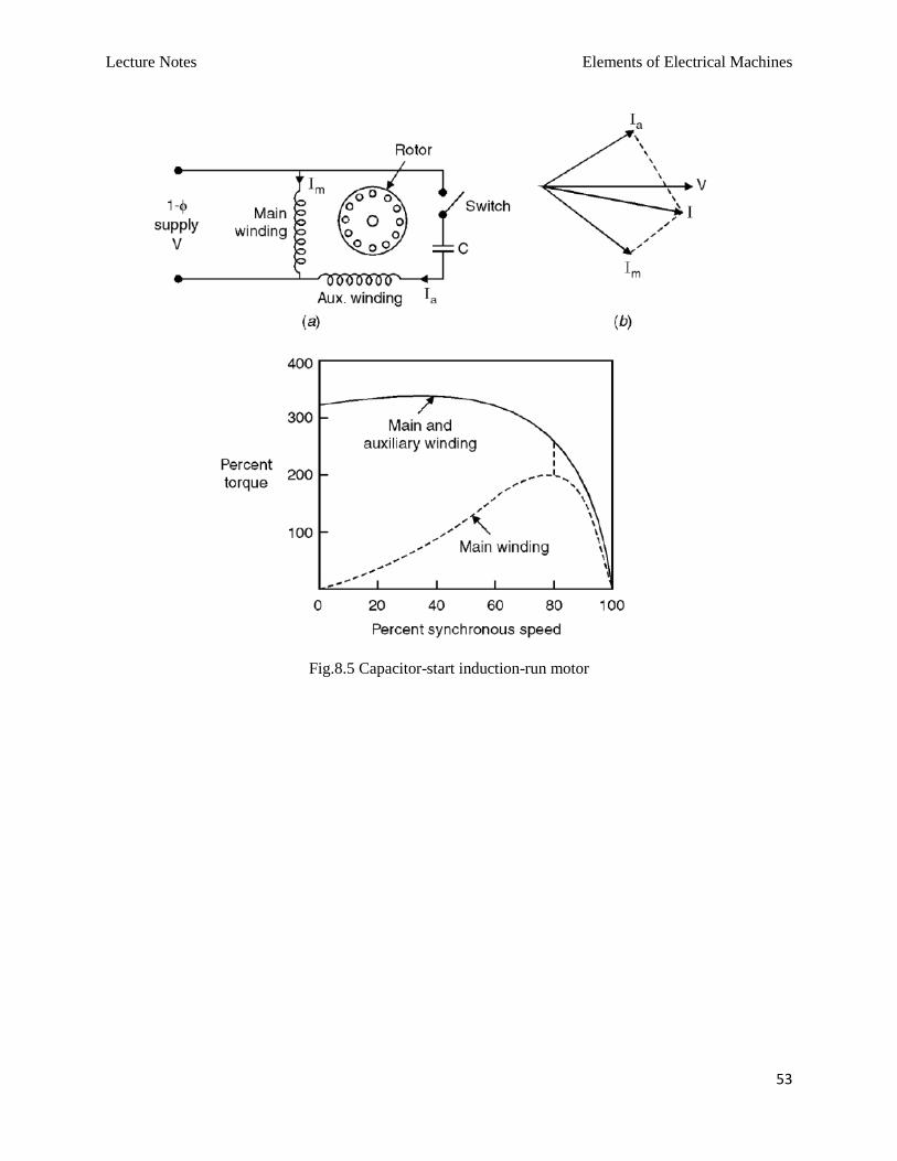
Fig.8.5 Capacitor-start induction-run motor
Lecture Notes Elements of Electrical Machines
54
Fig.8.6 Capacitor-start and run induction motor