elektromaten si - piutek
TRANSCRIPT

1.081
3
2
1
SG186F
SG186F
Subject to alterations. (20_Ca)
Series SG186FSI 260.5 - SI 500.5 GH
“Safedrive® FI” ELEKTROMATEN SI are special drives for industrial doors which require an anti-fallback device. The patented safety brake is built into the gear. The drive unit is fitted directly to the door shaft. Safedrive® ELEKTROMATEN comprises of: Worm gear with safety brake and hollow shaft, emergency manual operator, integrated limit switches and electrical motor.
Patented built-in safety brake Safety against failure of worm or wheel Independent of speed / direction Maintenance free, self-monitoring Excellent damping characteristics in operation
Approvals and certificates
Mounting Floating foot (standard fitting)
Special versions Increase of movements per hour Higher protection class Other voltages and frequencies ELEKTROMATEN SI with built-on frequency inverter (page 1.121)
Door controls Simple connection by means of non-interchangeable plug connections allowing simple exchange with other GfA control panels
Control voltage: 24 V Frequency: 50 Hz / 60 Hz Mains supply: 3~230 V, 3N~400 V, 3~400 V
Details of all GfA door controls can be found in Section 8.
Emergency manual operation Hand chain operator KNH 1
Limit switchesMechanical limit NES
2 operating, 2 emergency- and 2 auxiliary limit switches
Digital limit DES Absolute encoder, after a power failure, re-adjustment is not required
3
2
ELEKTROMATEN Type test according to: DIN EN 12453 DIN EN 60335-1 DIN EN 60335-2-103 TÜV NORD CERT GmbH
Built-in safety brake Certificate of conformity according to:DIN EN 12604 / 12605 ift Rosenheim GmbH
ELEKTROMATEN® SISafedrive®
For driving: Roller shutters and rolling grilles which require an anti-fallback device

1.082
SI 260.5 SG186F
SI 260.9 SG186F
SI 360.5 SG186F
SI 360.9 SG186F
SI 480.9 SG186F
SI 500.5 GH SG186F
2600 2600 3600 3600 4800 5000
5 9 5 9 9 5
80 80 80 80 / 100 100 100
8255 8255 8255 8255 8255 8255
16-000574-PR01
16-000574-PR01
16-000574-PR01
16-000574-PR01
16-000574-PR01
16-000574-PR01
2600 2600 3600 3600 4800 5000
5 / 5 9 / 9 5 / 5 9 / 9 9 / 9 5 / 5
1,5 3,0 2,0 3,0 3,0 2,5
3~230 / 400 3~230 / 400 3~230 / 400 3~230 / 400 3~230 / 400 3~230 / 400
50 50 50 50 50 50
6,7 / 3,9 11,9 / 6,9 8,6 / 4,7 11,9 / 6,9 11,4 / 6,6 10,0 / 5,8
6 6 6 6 6 8
10 10 10 10 (30) 10 (30) 10 (30)
182 182 215 215 255 261
123 128 125 127 130 129
50001996 50001996 50001996 50001996 50001996 50001997
Ø 80 10005218
Ø 80 10005217
Ø 80 10005216
Ø 80 10005215
Ø 100 10004323
Ø 100 10004324
Ø 100 10004344
SI 260 .5 .9 F [N] va [cm/s] va [cm/s]
SI 360 .5 .9 F [N] va [cm/s] va [cm/s]
SI 480.9 F [N] va [cm/s]
SI 500.5 GH F [N] va [cm/s]
298,5 x 7,1 11429 8,3 15,0 15824 8,3 15,0 -- -- -- --
323,9 x 7,1 10584 9,0 16,2 14655 9,0 16,2 19541 16,2 20355 9,0
368,0 x 8,0 9381 10,2 18,3 12990 10,2 18,3 17320 18,3 18041 10,2
406,4 x 8,8 8537 11,2 20,1 11820 11,2 20,1 15760 20,1 16417 11,2
419,0 x 10,0 8292 11,5 20,7 11481 11,5 20,7 15308 20,7 15945 11,5
457,2 x 10,0 -- -- -- -- -- -- 14082 22,5 14669 12,5
508,0 x 11,0 -- -- -- -- -- -- 12727 24,9 13258 13,8
Subject to alterations. (20_Ca)
ELEKTROMATEN Series
Output torque Nm
Output speed rpm
Output shaft / hollow shaft (Ø) mm
Locking torque 1 Nm
Safety brake (approval number)
Max. holding torque 2 Nm
Max. output speed OPEN / CLOSE for frequency inverter operation 3
rpm
Motor power kW
Supply voltage V
Operating frequency Hz
Operating current 4 A
Max. movements per hour 5/6
Limit switch range 7
Max. hand force KNH 8 N
Weight kg
Part no. installation drawing (dxf, dwg)
Part no. ELEKTROMATEN
1. Technical data
2. Selection chart
Generally applies: Degree of protection IP65, permissible temperature range -10 °C...+40 °C (+60 °C), operating sound pressure level SPL ‹70 dB(A)1 See 3.5 · 2 Maximum torque that may act on the output shaft of the drive unit when the door is stationary · 3 We recommend the selection of a special GfA ELEKTROMATEN-FI for use with frequency inverter, OPEN drive speed at 87 Hz, see 3.7 · 4 The max. current in door drives can reach up to 4x the rated operating current for limited periods, see 3.6 and 3.7 · 5 When using a temperature range of +40 °C...+60 °C use half of maximum movements per hour, see also 3.2 · 6 The specified value must be halved when considering cycles per hour according to EN 60335-2-103 · 7 Maximum revolutions of hollow shaft · 8 See 3.4
Roller shutters Tube EN 10220 [mm]
F = Lift [N] va = Initial speed [cm/s]
Includes 30 % friction for single-wall profiles (profile thickness 20 mm) Read note in 3.2

1.083
ELEKTROMATEN L1
SI 260.5 897SI 260.9 942SI 360.5 922SI 360.9 942SI 480.9 972
4.1 SI 260.5 – SI 480.9 SG186F
7
6
3
5
1
2
4 Ø D H B
80 85,4 22100 160,4 28
Subject to alterations. (20_Ca)
3.1 European directive
In accordance with the product standard EN 13241 Doors- and EN 12453 Safety in use of power operated doors-Requirements.
3.6 Motor overload protection
Motor overload protection must be able to withstand 4x the operating motor current because the starting current of the drive unit can reach these levels for short periods.
3.2 Selection chart / Movements per hour
The specified movements per hour (see Technical data) apply to an even distribution and the limit switch range first mentioned and must not be exceeded. For other limit switch ranges or heavily used doors, the drag forces must be reduced (enquire).The selection chart includes 30 % friction for roller shutters with single-wall profiles (profile thickness 20 mm) and 10 % friction for sectional doors.Reduce the weight by a further 20 % for vertical lifted doors and insulated shutters with double walled, thick and / or deep sections. Do not calculate using the tube diameter. The high-est torque will occur normally after 1-2 turns of the barrel from close.
3.3 Gear self-braking / Brake
Drives without an electric brake have a self-sustaining worm gear and stop automatically.On drives with an electric brake, stopping is achieved by the external brake. Brake inspection must always be carried out by qualified service engineers.
3.7 Use with external frequency inverter
We recommend ELEKTROMATEN FI with an integrated fre-quency inverter (page 1.121).For external frequency inverters applies:A higher than recommended drive speed puts extra load onto the gear. This extra load must be taken into account when sizing a drive by reducing the available output torque.Increasing the drive speed by 10 % reduces the admissible drive torque by 5 %. In the case of higher drive speeds reduce the drive torque accordingly (enquire if necessary). The admissible drive speeds may not be exceeded (see Technical data). The operating forces must comply with EN 12453, and the corresponding EMC directives must like-wise be observed.If selecting a frequency inverter, note that the starting current of the drive unit can reach 4x the operating motor current.
In accordance with EN 12453 and 12604 hand force up to 390 N is permissible. For large, heavy doors, manual operation is only used for closing the door. In the case of drive units with an electric brake; emergency manual operation is carried out against the closed brake (Read note in 3.3).
3.4 Manual operation
3. Notes
3.8 Cable / Cable drums
When calculating the cable size the max. permitted door weight is required with a safety of 6x for the cables require-ment of EN 12604. Cable drum selection – ensure that two turns of the cable remain on the drum at all times. The diameter of the cable drum must be at least 20x the diameter of the cable.
The permissible loads on walls, fastenings, mountings and transmission elements must not be exceeded, even for maxi-mum holding torques or locking torques.
3.5 Locking torque / Holding torque
4. Dimensions
1 Worm gear with safety brake
2 Motor
3 Limit switch
4 Emergency manual operation KNH
5 Floating foot
6 Brake
7 Assembling aid
Permitted installation: Horizontal with an additional torque mount system, see 6
1.084
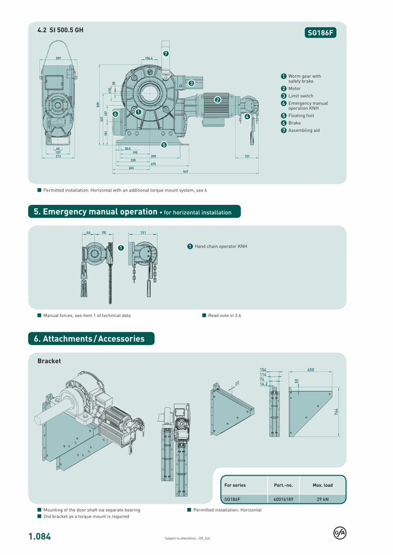
SG186F4.2 SI 500.5 GH
SG186F 40016189 29 kN
7
6
3
5
1
2
4
1
Subject to alterations. (20_Ca)
Bracket
Mounting of the door shaft via separate bearing 2nd bracket as a torque mount is required
For series Part.-no. Max. load
6. Attachments / Accessories
Permitted installation: Horizontal
1 Worm gear with safety brake
2 Motor
3 Limit switch
4 Emergency manual operation KNH
5 Floating foot
6 Brake
7 Assembling aid
Permitted installation: Horizontal with an additional torque mount system, see 6
1 Hand chain operator KNH
Manual forces, see item 1 of technical data Read note in 3.4
5. Emergency manual operation • for horizontal installation

1.121
SG186F
2
1
Subject to alterations. (20_If)
ELEKTROMATEN® SI FISafedrive® with built-on frequency inverter
For driving: Non-balanced sectional doors, roller shutters and rolling grilles which require an anti-fallback device
Series SG186F SI 500.10 FI
“Safedrive® FI” ELEKTROMATEN SI are special drives for industrial doors which require an anti-fallback device. The patented safety brake is built into the gear. The drive unit is fitted directly to the door shaft. Safedrive ELEKTROMATEN SI FI comprises of: Worm gear with safety brake and hollow shaft, emergency manual operator, integrated limit switches and electrical motor with built-on frequency inverter.
Patented built-in safety brake Safety against failure of worm or wheel Independent of speed / direction Maintenance free, self-monitoring Excellent damping characteristics in operation
Built-on frequency inverter to be used with door controls TS 970, TS 971 or TS 981
Individual adjustable output speed 1) The speed appears directly into the display – extra work to evaluate
frequency and speed is not required Soft start and soft stop Automatic optimising of acceleration and deceleration speed Adjustable distance for acceleration and deceleration speed Individual adjustment and programming of all functions from the
ground by a selector switch with digital display
Approvals and certificates
1) See 3.6
Mounting Floating foot (Fitting requires a torque mount system)
Door controls Simple connection by means of non-interchangeable plug connections allowing simple exchange with other GfA control panels
Control voltage: 24 V Frequency: 50 Hz / 60 Hz Mains supply: 3N~400 V, 3~400 V
Details of all GfA door controls can be found in Section 8.
Built-in safety brake Certificate of conformity according to:DIN EN 12604 / 12605 ift Rosenheim GmbH
Emergency manual operation Hand chain operator KNH 1
ELEKTROMATEN and FI-motors Type test according to: DIN EN 12453 DIN EN 60335-1 DIN EN 60335-2-103 TÜV NORD CERT GmbH
Limit switchesDigital limit DES
Absolute encoder, after a power failure, re-adjustment is not required
2

1.122
SG186F
5000
6-102-52-5
100
8255
16-000574-PR01
5000
4,50
3~400
50 / 60
12,4
8
10
261
138
50001578
10004095
323,9 x 7,1 20355 3,6 - 18,0
368,0 x 8,0 18041 4,1 - 20,3
406,4 x 8,8 16417 4,5 - 22,3
419,0 x 10,0 15945 4,6 - 23,0
457,2 x 10,0 14669 5,0 - 25,0
508,0 x 11,0 13258 5,5 - 27,6
Subject to alterations. (20_If)
F = Lift [N] vb = Range of speed
Includes 30 % friction for single-wall profiles (profile thickness 20 mm) Read note in 3.2
ELEKTROMATEN Series
SI 500.10 FI
Output torque Nm
Output speed OPEN CLOSE > 2,5 m CLOSE ≤ 2,5 m 1
rpm
Output shaft / hollow shaft (Ø) mm
Locking torque 2 Nm
Safety brake (approval number)
Max. holding torque 3 Nm
Motor power kW
Supply voltage V
Operating frequency Hz
Operating current A
Max. movements per hour 4/5
Limit switch range 6
Max. hand force KNH 7 N
Weight kg
Part no. installation drawing (dxf, dwg)
Part no. ELEKTROMATEN
Roller shutters Tube EN 10220 [mm]
SI 500.10 FI F [N] vb [cm/s]
1. Technical data
2. Selection chart
Generally applies: Degree of protection IP65, permissible temperature range +5 °C...+40 °C (+60 °C), operating sound pressure level SPL ‹70 dB(A)1 See 3.6 · 2 See 3.5 · 3 Maximum torque that may act on the output shaft of the drive unit when the door is stationary · 4 When using a temperature range of +40 °C...+60 °C use half of maximum movements per hour, see also 3.2 · 5 The specified value must be halved when considering cycles per hour according to EN 60335-2-103 · 6 Maximum revolutions of hollow shaft, other limit switch ranges on request · 7 See 3.4

1.123
SG186F
7
6
3
5
12
4
Subject to alterations. (20_If)
3.1 European directive
In accordance with the product standard EN 13241 Doors- and EN 12453 Safety in use of power operated doors-Requirements.
Permitted installation: Horizontal with an additional torque mount system, see 6
3. Notes
4. Dimensions
SI 500.10 FI
3.2 Selection chart / Movements per hour
The specified movements per hour (see Technical data) apply to an even distribution and the limit switch range first mentioned and must not be exceeded. For other limit switch ranges or heavily used doors, the drag forces must be reduced (enquire).The selection chart includes 30 % friction for roller shutters with single-wall profiles (profile thickness 20mm) and 10 % friction for sectional doors.Reduce the weight by a further 20 % for vertical lifted doors and insulated shutters with double walled, thick and / or deep sections. Do not calculate using the tube diameter. The high-est torque will occur normally after 1-2 turns of the barrel from close.
3.3 Gear self-braking / Brake
Drives without an electric brake have a self-sustaining worm gear and stop automatically.On drives with an electric brake, stopping is achieved by the external brake. Brake inspection must always be carried out by qualified service engineers.
In accordance with EN 12453 and EN 12604 hand force up to 390 N is permissible. For large, heavy doors, manual operati-on is only used for closing the door. In the case of drive units with an electric brake; emergency manual operation is car-ried out against the closed brake (Read note in 3.3).
3.4 Manual operation
3.6 Output speed
The maximum admissible speed is dependent on the door construction and type of the door. All materials must be desi-gned to be used for doors with higher speeds.The admissible closing speed shall be adjusted so that the ope-rating forces must comply with EN 12453
The permissible loads on walls, fastenings, mountings and transmission elements must not be exceeded, even for maxi-mum holding torques or locking torques.
3.5 Locking torque / Holding torque
1 Worm gear with safety brake
2 Motor with built-on frequency inverter
3 Limit switch
4 Emergency manual operation KNH
5 Floating foot
6 Brake
7 Assembling aid

1.124
SG186F 40016189 29 kN
1
Subject to alterations. (20_If)
Bracket
Mounting of the door shaft via separate bearing 2nd bracket as a torque mount is required
For series Part.-no. Max. load
6. Attachments / Accessories
Permitted installation: Horizontal
1 Hand chain operator KNH
5. Emergency manual operation • for horizontal installation
Manual forces, see item 1 of technical data Read note in 3.4