door control ts 971 - gfa · door control ts 971 51171542 c 10.2013 0000000 0000 51171542 xxxxx. 2...
TRANSCRIPT
aus
Installation instructions
Door control TS 971
51171542 c 10.2013
0 0 0 0 0 0 0 0 0 0 0 5 1 1 7 1 5 4 2 XXXXX
2
GfA-ELEKTROMATEN Australia Pty Ltd P.O. Box 267 Roseville 2069 NSW Telephone: 02 9882 2782 Facsimile: 02 9882 2783 Email: [email protected] Web: www.gfa-elektromaten.net

3
Contents 1 General safety information ............................................................................................ 6 2 Technical data .............................................................................................................. 7 3 Mechanical installation .................................................................................................. 8 4 Electrical installation ..................................................................................................... 9
Connection cable connection overview ........................................................................... 10 Limit switch assignment for screwable version until year of manufacture of 1997 .......... 11 Assignment of individual limit switches ........................................................................... 11 Carrying out the electrical installation .............................................................................. 12 Mains connection ............................................................................................................ 13 Mains connection to control ............................................................................................ 13 Completing the electrical installation ............................................................................... 13 Overview of control ......................................................................................................... 14
5 Starting up the control ................................................................................................. 15 DES: Rapid adjustment of limits ...................................................................................... 15 NES: Fast adjustment of limit switches ........................................................................... 16
6 Electrical installation – control accessories .................................................................. 17 X1 External supply .......................................................................................................... 17 X3 Emergency stop ......................................................................................................... 17 X4 Automatic closing On/Off ........................................................................................... 17 X5 Control device ............................................................................................................ 17 X6 Photo cell ................................................................................................................... 17 X6 Light curtain ............................................................................................................... 18 X7 Radio receiver............................................................................................................ 18 X7 Pull switch .................................................................................................................. 18 X8 Intermediate stop ....................................................................................................... 18 X20 / X21 Red / green traffic light ................................................................................... 18 X20 / X21 Magnetic brake ............................................................................................... 18 Connection of spiral cable ............................................................................................... 19 "WSD" Wireless Safety Device ....................................................................................... 20 8K2 electrical safety edge system on "WSD" door module ............................................. 20 OSE optical safety edge system 1 on "WSD" door module ............................................. 20 OSE optical safety edge system 2 on "WSD" door module ............................................. 21 Door safety switch on "WSD" door module ..................................................................... 21

4
Teaching in of "WSD" door module ................................................................................. 22 Completing the electrical installation ............................................................................... 22
7 Control programming .................................................................................................. 23 8 Table of menus ........................................................................................................... 24
Operating mode .............................................................................................................. 24 Door positions ................................................................................................................. 25 Door functions, ................................................................................................................ 26 Safety functions ............................................................................................................... 30 DU/FI settings ................................................................................................................. 31 Advanced door functions ................................................................................................. 32 Maintenance cycle counter .............................................................................................. 33 Reading out memory ....................................................................................................... 34 Delete all settings ............................................................................................................ 34 Reading out WSD data .................................................................................................... 35
9 Safety devices ............................................................................................................ 36 X2: Input, door safety switch ........................................................................................... 36 X2: Input, safety edge system ......................................................................................... 38 Installation of the spiral cable .......................................................................................... 39 Integrated "WSD" wireless safety device ........................................................................ 42 EMERGENCY operation ................................................................................................. 44 X3: Input, emergency stop .............................................................................................. 44
10 Functional description ................................................................................................. 45 X: 24 V DC voltage supply .............................................................................................. 45 X1: Mains supply line for control and external supply ..................................................... 45 X4: Input, automatic closing Off/On ................................................................................. 46 X5: Input, control device .................................................................................................. 46 X6: Input, "Through / reflective photo cell" or light curtain ............................................... 47 X7: Input, pull switch/radio receiver ................................................................................. 50 Internal radio receiver ...................................................................................................... 51 Teach-in of radio transmitter ........................................................................................... 51 Deleting an individual radio transmitter ........................................................................... 52 Deleting all radio transmitters .......................................................................................... 52 X8: Input, intermediate stop On/Off ................................................................................. 53

5
X20 / X21: Potential-free relay contacts .......................................................................... 54 Force monitoring (DES only) ........................................................................................... 54 Travel time monitoring (NES only) .................................................................................. 55 UBS system .................................................................................................................... 56 UBS connection .............................................................................................................. 56 Reversing duration adjustment ....................................................................................... 56 Maintenance cycle counter ............................................................................................. 57 Short-circuit/overload display .......................................................................................... 57 Display for active "WSD" wireless safety device ............................................................. 57 Standby function ............................................................................................................. 58 Lighting of the internal control device .............................................................................. 58
11 Status display ............................................................................................................. 59 Faults .............................................................................................................................. 59 Commands ...................................................................................................................... 64 Status indications ............................................................................................................ 65
12 Explanation of symbols ............................................................................................... 66 13 Declaration of Incorporation/Declaration of Conformity ................................................ 68
Symbols
Warning - Risk of injury or danger to life!
Warning - Danger to life from electric shock !
Note - Important information!
▶ Prompt - Required action!
Illustrations show example products. Differences from the delivered product are possible.

6
1 General safety information
Specified normal use The door control is intended for a power-operated door with a drive unit (NES/DES GfA limit switch system). The safe operation is only guaranteed with specified normal use. The drive unit is to be protected from rain, moisture and aggressive ambient conditions. No liability for damage caused by other applications or non-observance of the information in the manual. Modifications are only permitted with the agreement of the manufacturer. Otherwise the Manufacturer’s Declaration shall be rendered null and void. Safety information Installation and initial operation tasks are to be performed by skilled personnel only. Only trained electrical craftsmen are permitted to work on electrical equipment. They must assess the tasks assigned to them, recognise potential danger zones and be able to take appropriate safety measures. Installation work is only to be carried out with the supply off. Observe the applicable regulations and standards. Coverings and protective devices Do not operate unless corresponding coverings and protective devices are installed. Ensure that gaskets are fitted correctly and that cable glands are correctly tightened. Spare parts Only use original spare parts.

7
2 Technical data
Series TS 971
Dimensions W x H x D 155 x 386 x 90 mm
Installation Vertical
Vibration Free of vibration Installation
Operating frequency 50/60 Hz
Supply voltage 1 N~220 V, PE 3 N~220-400 V, PE 3~220-400 V, PE
Output power for drive unit, maximum 3 kW
Protection per phase, on-site 10-16 A
External supply voltage: (internal electronic protection)
24 V DC
0.35 A
External supply voltage: X1/L, X1/N (protection via F1 micro-fuse)
1 N~230 V
1.6 A time-lag
Control inputs 24 V DC
Type 10 mA
Type of relay contacts (2 pcs) Max. current of 1A at 230VAC, and 0.4A at 24VDC (The use of LED lamps is recommended.)
Potential-free changeover contacts
Loading of relay contacts, ohmic/inductive
230 V AC
1 A
Control power consumption 10 VA
Temperature range Operation: -10..+50 Storage: +0..+50 °C
Air humidity to 93 % non-condensing
Protection class of housing IP65
Compatible GfA limit switch NES; DES
Integrated radio receiver WSD / radio transmitter 2.4GHz / 434MHz

8
3 Mechanical installation
Control installation! Indoor use only Mount on a level surface free of vibration Only mount in the vertical position Door must be in clear view from place of assembly
Requirements The permissible loads on walls, fastenings, mountings and transmission elements must not be exceeded.
Mounting
The control is mounted via 4 elongated holes

9
4 Electrical installation
Warning – Danger to life from electric shock! Disconnect the cables (mains OFF) and check that the supply is off Observe the applicable regulations and standards Ensure proper electrical connection Use suitable tools
On-site backup fuse and disconnector unit! Only use current sensitive earth leakage circuit breakers type B for FI-drive units Connection to the indoor installation via an all-pole disconnector unit, with current
≥ 10 A as per EN 12453 (e.g. CEE plug connector, main switch)
Read the drive unit installation instructions!

10
Connection cable connection overview
DES and NES Motor connection cable
DES Connection cable limit switch
MOT X13 Motor plug DES X12 Limit switch plugPin Core Term. Pin Core Term.1 3 W Phase W 1 5/wh 1 +24 V safety circuit2 2 V Phase V 2 6/bn 2 Channel B (RS485)3 1 U Phase U 3 7/gn 3 Ground4 4 N Neutral conductor (N) 4 8/ye 4 Channel A (RS485)5 PE PE 5 9/gy 5 Safety circuit 6 10/pk 6 8 V DC supply voltage
NES Connection cable NES X12 Limit switch plug Pin Core Term. 1 5/wh 11 Limit switch common +24 V, wire link on X12 5, 7, 9, 11, 142 6/bn 12 S5 Auxiliary limit switch, testing or safety edge function3 7/gn 6 S3 Open limit switch 4 8/ye 15 S6 Auxiliary limit switch, relay function or intermediate stop5 9/gy 8 S4 Close limit switch 6 10/pk 4 Safety circuit

11
Limit switch assignment for screwable version until year of manufacture of 1997
F1 Thermal contact X12 Limit switch board G1 Rectifier S1 Emergency open limit switch M1 Motor S2 Emergency close limit switch S10 Emergency manual operation S3 Open limit switch W1 Connection cable S4 Close limit switch Y1 Spring-loaded brake S5 Auxiliary limit switch S6 Auxiliary limit switch
Assignment of individual limit switches
A1 Terminal box S3 Open limit switch F1 Thermal contact S4 Close limit switch M1 Motor S5 Auxiliary limit switch S10 Emergency manual operation S6 Auxiliary limit switch W1 Connection cable
5 6 7 10 9 3 2 1 4 (N)
S6 S5 S3 S1 S2 S4
S10 F1G1
Y1
1
3
2
45
X12
W1
M1
5 67 109321 4PE
M1 S10 F1S4S3 S5 S6
W1
A1

12
Carrying out the electrical installation
▶ Remove covers. ▶ Open cable entry ① or ②.
▶ Insert and connect connection cable in the open cable entry ① (from below) or ② (from above).
▶ Properly tighten cable glands.
Attention - Damage to components! Open cable entry with suitable tool Install cable entries and/or cable glands
13
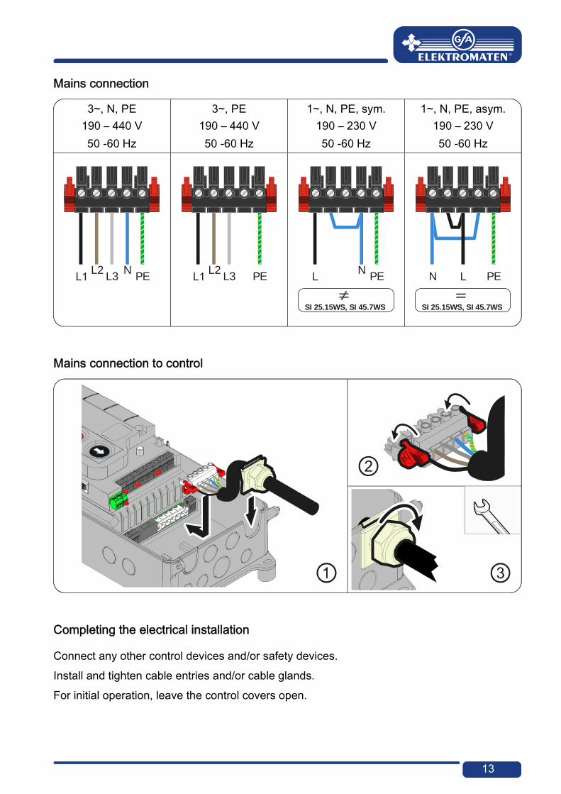
Mains connection
3~, N, PE 190 – 440 V 50 -60 Hz
3~, PE 190 – 440 V 50 -60 Hz
1~, N, PE, sym. 190 – 230 V 50 -60 Hz
1~, N, PE, asym. 190 – 230 V 50 -60 Hz
Mains connection to control
Completing the electrical installation
Connect any other control devices and/or safety devices. Install and tighten cable entries and/or cable glands. For initial operation, leave the control covers open.
L2L3
NPE
L2L3 PE
NPE
SI 25.15WS, SI 45.7WS
N PE
SI 25.15WS, SI 45.7WS
3
14
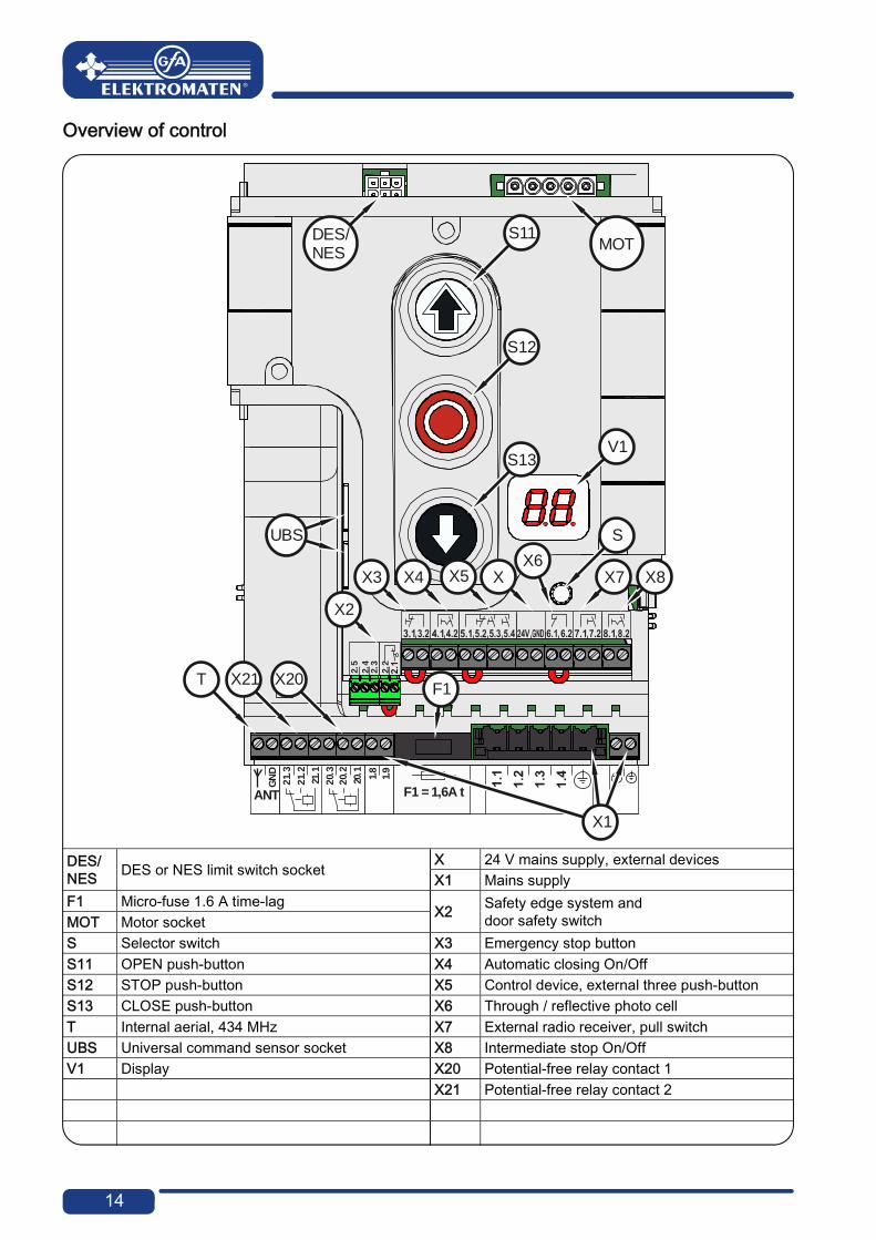
Overview of control
DES/ NES DES or NES limit switch socket
X 24 V mains supply, external devices X1 Mains supply F1 Micro-fuse 1.6 A time-lag
X2 Safety edge system and door safety switch MOT Motor socket
S Selector switch X3 Emergency stop button S11 OPEN push-button X4 Automatic closing On/Off S12 STOP push-button X5 Control device, external three push-button S13 CLOSE push-button X6 Through / reflective photo cell T Internal aerial, 434 MHz X7 External radio receiver, pull switch UBS Universal command sensor socket X8 Intermediate stop On/Off V1 Display X20 Potential-free relay contact 1 X21 Potential-free relay contact 2
2.3
2.5
2.2
2.4
20.1 1.8
1.9
ANT
GN
D
20.2
20.3
21.1
21.2
21.3
F1 = 1,6A t
V1
MOTDES/NES
S11
S12
S13
X20X21T
X3
X2
X4 X5 XX6
X7 X8
F1
UBS S
X1

15
5 Starting up the control
▶ Plug-in or switch on the mains supply line
DES: Rapid adjustment of limits
1. Check rotating direction
2. Move to final limit position open 3. Save limit position
4. Move to final limit position close 5. Save limit position
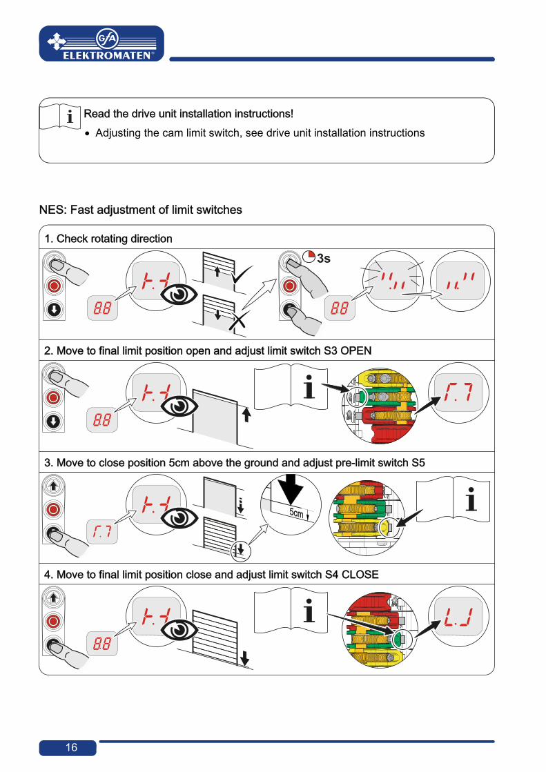
Note! Fast adjustment is complete, "Hold-to-run" door operating mode active Change of OPEN/CLOSE limit position via Parameter "1.1" to "1.4" Pre-limit safety edge adjusts automatically Changing the pre-limit position is possible via Parameter "1.5"
16
Read the drive unit installation instructions! Adjusting the cam limit switch, see drive unit installation instructions
NES: Fast adjustment of limit switches
1. Check rotating direction
2. Move to final limit position open and adjust limit switch S3 OPEN
3. Move to close position 5cm above the ground and adjust pre-limit switch S5
4. Move to final limit position close and adjust limit switch S4 CLOSE

17
0
6 Electrical installation – control accessories X1 Exter nal supply X3 Emergency stop X4 Automatic cl osing On/Off
X1 External supply X3 Emergency stop X4 Automatic closing On/Off
A1 External device A2 Control device A3 Control device Emergency stop Key-switch
X5 Contr ol device
X5 Control device
A4 Key-switch A6 Three push-button
X6 Photo cell
X6 Photo cell
A8 Reflective photo cell
Through photo cell
Through photo cell
A9 Transmitter A11 Transmitter A10 Receiver A12 Receiver
X1
A1
X3
A2 2
1
S15
X4
A3
1 2
4
3S17
X5
P
1
S172
A4
X5
3
2
1
S14
4
3
2
1
S16
2
1
S15
A6 X5
1 2 3 4 5
24V
X6
A8
X6
1 2
24V
A9
1 2 3 4 5
24V
A10
X6
1 2
24V
A11
1 2 3
24V
A12PNP

18
X6 Li ght curtai n
X6 Light curtain
X20 Function relay Light curtain Light curtain X21 Function relay A25 Transmitter A27 Transmitter Test light curtain A26 Receiver A28 Receiver
X7 Radio receiver X7 Pull switch X8 Inter medi ate s top
X7 Radio receiver X7 Pull switch X8 Intermediate stop
X20 / X21 R ed / green tr affic li ght X20 / X21 Magnetic brake
X20 / X21 Red / green traffic light X20 / X21 Magnetic brake
H1 Traffic light, green G1 RectifierH2 Traffic light, red Y1 Magnetic brake
X21 21.
1
21.
2
21.
3
24V
24V*
X20 20
.1
20
.2
20
.3
24V
24V*
X6
1 2
24V
A25
1 2 3 4 5
24V
A26
24V24V*
PNP
X6
1 2
24V
A27
1 2 3
24V
A28
24V24V*
1 2 3 4
24V
X7
A13 A14
4
3
X7
S19
A15
1 2
4
3
S17
X8
20.1
20.2
20.3
H1
1.9
1.8
21.1
21.2
21.3X20/
H2
20.1
20.2
20.3
1.9
1.8
21.1
21.2
21.3X20/ Y1
G1C1
19
Connecti on of spiral cabl e
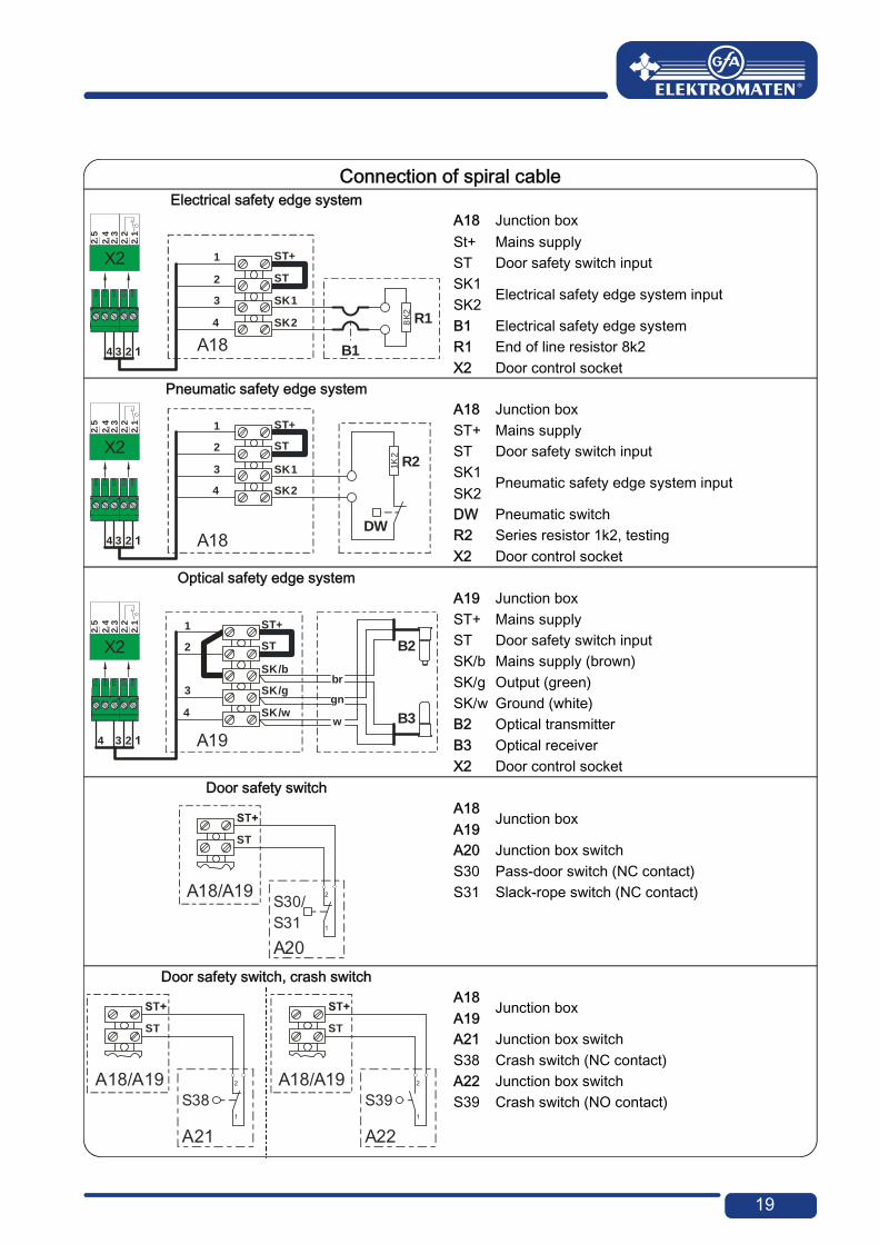
Connection of spiral cableElectrical safety edge system
A18 Junction box St+ Mains supplyST Door safety switch input SK1
Electrical safety edge system input SK2B1 Electrical safety edge system R1 End of line resistor 8k2 X2 Door control socket
Pneumatic safety edge systemA18 Junction box ST+ Mains supply ST Door safety switch input SK1
Pneumatic safety edge system input SK2DW Pneumatic switch R2 Series resistor 1k2, testing X2 Door control socket
Optical safety edge system A19 Junction box ST+ Mains supply ST Door safety switch input SK/b Mains supply (brown) SK/g Output (green) SK/w Ground (white) B2 Optical transmitter B3 Optical receiver X2 Door control socket
Door safety switch
A18 Junction box
A19A20 Junction box switch S30 Pass-door switch (NC contact) S31 Slack-rope switch (NC contact)
Door safety switch, crash switchA18
Junction box A19A21 Junction box switch S38 Crash switch (NC contact) A22 Junction box switch S39 Crash switch (NO contact)
234
2.1
2.3
2.5
2.2
2.4
X2 1
2
3
4
ST+
ST
SK1
SK2
A18 B1
8K
2
R1
234
2.1
2.3
2.5
2.2
2.4
X21
2
3
4
ST+
ST
SK1
SK2
A18DW
1K2
R2
234
2.1
2.3
2.5
2.2
2.4
X21
2
3
4
ST+
ST
SK/b
SK/g
SK/w
A19
br
gn
w B3
B2
ST
A18/A19
A20
2
1
S30/S31
ST
A18/A19
A21
2
1
S38
ST
A18/A19
A22
2
1
S39

20
"WSD" Wireless Safety D evice
"WSD" Wireless Safety DeviceOpen "WSD" door module
A23 "WSD" door module ⑥ ST2 System 2 connection cable socket① P1 Door module push-button ⑦ S2 Safety edge evaluation switch: ② S1 Switch "A" System 1, "B" System 2 Optical (upper changeover position < "IR") ③ G1 Lithium battery, 9000 mAh Electrical (lower changeover position) ④ X1/2 Door safety switch connection ⑧ KL1 Terminal ⑤ ST3 Optical sensor or system 2 connection
cable socket Electrical safety edge system
⑨ ST1 Optical sensor socket
8K2 elec trical safety edge sys tem on "WSD" door module
8K2 electrical safety edge system on "WSD" door module
OSE optical safety edge sys tem 1 on "WSD" door modul e
OSE optical safety edge system 1 on "WSD" door module
8765
44
3
2
1

21
OSE optical safety edge sys tem 2 on "WSD" door modul e
OSE optical safety edge system 2 on "WSD" door module A23 WSD door module A24 System 2 end box
Door safety switch on "WSD" door module
Door safety switch on "WSD" door module
A24 System 2 end box
A24
2
1
S38
A21
2
1S38A21
2
1
S38
A24
X1 / X2

22
Teachi ng in of "WSD" door modul e
Teaching in of "WSD" door moduleInsert battery Insert or switch on mains supply
Activate
Teach-in "WSD" door module found, dot on the right is statically lit
Note! Use of a safety edge system only possible via menu "0.1",
door operating mode "3", "4" or "6"
Completing the electrical installation
If required, connect other electrical equipment and/or safety devices, install cable entries and/or cable glands.

23
7 Control programming
1. Programming can only be accessed after rapid adjustment of limit switches!
2. Select menu and confirm
3.a) Set and save functions
3.b) Set and save positions
4. Exit programming
24
8 Table of menus Operati ng mode
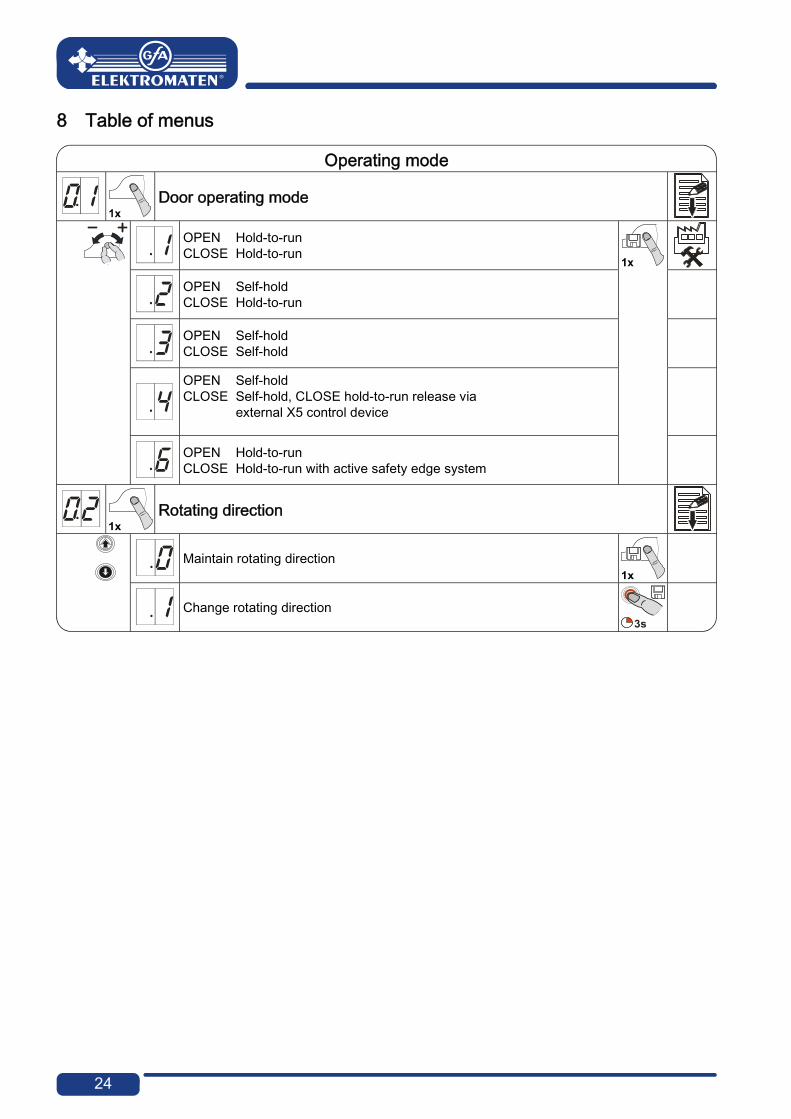
Operating mode
Door operating mode
OPEN CLOSE
Hold-to-run Hold-to-run
OPEN CLOSE
Self-hold Hold-to-run
OPEN CLOSE
Self-hold Self-hold
OPEN CLOSE
Self-hold Self-hold, CLOSE hold-to-run release via external X5 control device
OPEN CLOSE
Hold-to-run Hold-to-run with active safety edge system
Rotating direction
Maintain rotating direction
Change rotating direction

25
Door positions
Door positions
OPEN final limit position, coarse correction
OPEN/CLOSE door movement
CLOSE final limit position, coarse correction
OPEN/CLOSE door movement
OPEN final limit position, fine correction
Without door movement,[ + ] correct in OPEN [ – ] correct in CLOSE
CLOSE final limit position, fine correction
Without door movement,[ + ] correct in OPEN [ – ] correct in CLOSE
Pre-limit safety edge, fine correction
Without door movement,[ + ] correct in OPEN [ – ] correct in CLOSE
Intermediate stop
OPEN/CLOSE door movement For NES: Set additional S6 limit switch
Adjust position of relay 1 switching point Select relay function via menu 2.7
OPEN/CLOSE door movement For NES: Set additional S6 limit switch
Adjust position of relay 2 switching point Select relay function via menu 2.8
OPEN/CLOSE door movement For NES: Set additional S6 limit switch
26
Door functi ons,
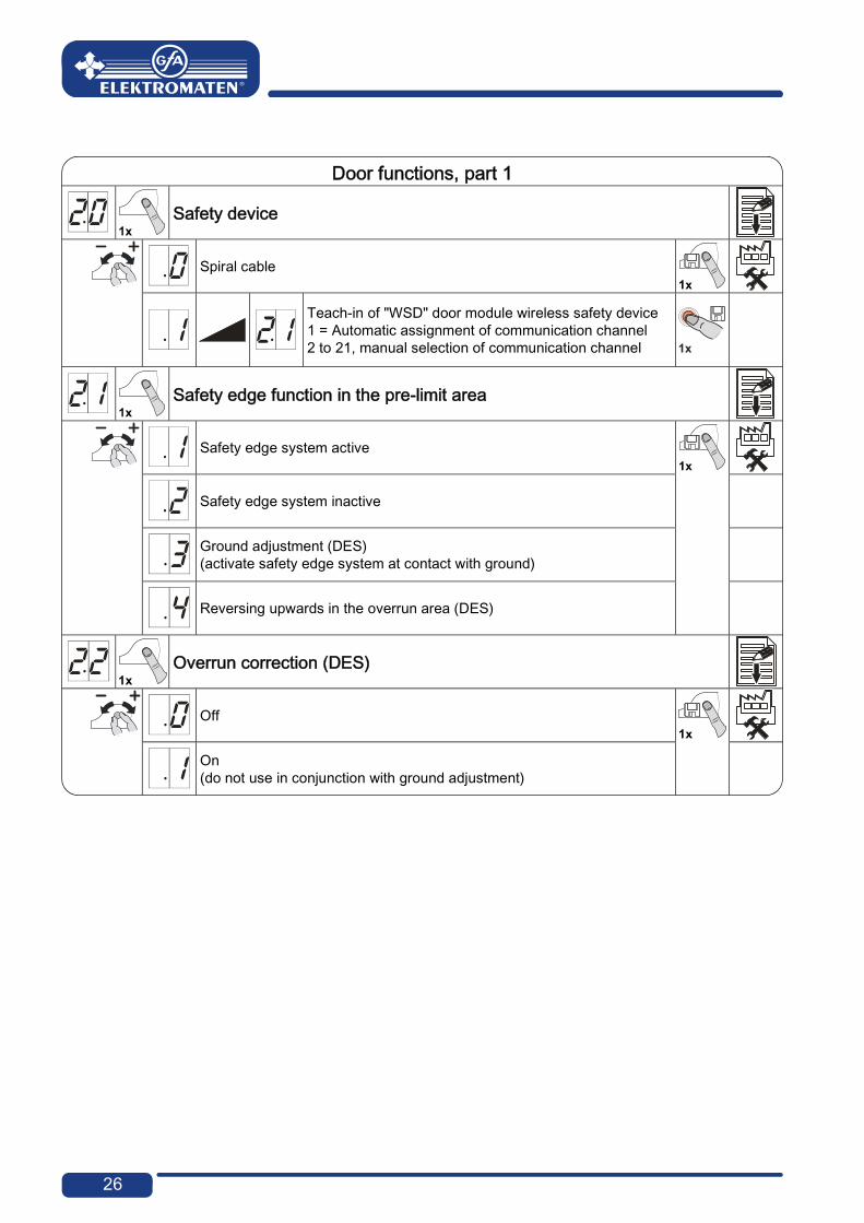
Door functions, part 1
Safety device
Spiral cable
Teach-in of "WSD" door module wireless safety device 1 = Automatic assignment of communication channel 2 to 21, manual selection of communication channel
Safety edge function in the pre-limit area
Safety edge system active
Safety edge system inactive
Ground adjustment (DES) (activate safety edge system at contact with ground)
Reversing upwards in the overrun area (DES)
Overrun correction (DES)
Off
On (do not use in conjunction with ground adjustment)

27
Door functions, part 2
Automatic closing
0 to 240 seconds
Advanced photo cell function
Off
Cancel automatic closing and CLOSE command
Vehicle recognition Cancel automatic closing and CLOSE command if photo cell is activated > 1.5 seconds
Reversing
0 = Off 1 to 10 safety device activations
Pull switch or radio receiver function X7
Pulse type 1 Door is not in OPEN final limit position OPEN command Door is in OPEN final limit position CLOSE commandPulse type 2 Command sequence OPEN – STOP – CLOSE – STOP – OPEN
Pulse type 3 OPEN command only

28
Door functions, part 3
Relay function on X20 Teach in door position via menu 1.7 (DES only)
Relay function on X21 Teach in door position via menu 1.8 (DES only)
X20 X21
Off
Pulse signal for 1 second
Permanent signal
Red lamp, permanent light during door movement OPEN final limit position 3 seconds flashing CLOSE final limit position 3 seconds flashing
Red lamp, permanent light during door movement OPEN final limit position 3 seconds flashing CLOSE final limit position Off
Red lamp, permanent light during door movement OPEN final limit position 3 seconds permanent light CLOSE final limit position 3 seconds permanent light
Red lamp, permanent light during door movement OPEN final limit position 3 seconds permanent light CLOSE final limit position Off
Dock leveller release or permanent green light Is active only in OPEN final limit position
Permanent contact in CLOSE final limit position
Light sensing device 1 second pulse at each OPEN command
Permanent contact at door position
Brake control Active during operation Inactive at stop
Light curtain test, etc. Test prior to each closing operation

29
Door functions, part 4
Intermediate stop function
All command inputs are active
Input X7.2 and internal radio receiver active
Input X5.4 and OPEN push-button of control active

30
Safety functions
Safety functions
Force monitoring (DES)
0 = Off Adjustable from 2 % to 10 % overload
Interruption to photo cell operation
Off
On (teach in the same reference position twice)
Travel time monitoring (NES) only
0 = Off 0 to 90 seconds
Door safety switch function (input X2.2 or WSD)
Slack-rope or pass-door switch
Crash detector (NC contact) Hold-to-run after activation
Crash detector (NO contact) Hold-to-run after activation
Crash detector (NC contact) Reverse, reset in OPEN final limit position following contact reset, otherwise hold-to-run
Crash detector (NO contact) Reverse, reset in OPEN final limit position following contact reset, otherwise hold-to-run
Automatic opening (set automatic closing under menu 2.3)
0 = Off 0 to 99 minutes
Reversing duration adjustment
[ + ] slower [ – ] faster

31
DU/FI settings
DU/FI settings
OPEN output speed
Output speed in rpm
CLOSE output speed
Output speed in rpm
Increased CLOSE output speed To opening height of 2.5 m
Output speed in rpm
0 = Off
Changeover position to CLOSE output speed (observe minimum opening height of 2.5 m!)
OPEN/CLOSE door movement
OPEN acceleration
DU Steps of 1.0 seconds FI Steps of 0.1 seconds
CLOSE acceleration
DU Steps of 1.0 seconds FI Steps of 0.1 seconds
OPEN deceleration
DU Steps of 1.0 seconds FI Steps of 0.1 seconds
CLOSE deceleration
DU Steps of 1.0 seconds FI Steps of 0.1 seconds
OPEN/CLOSE crawling speed
Output speed in rpm
32
Advanced door functi ons
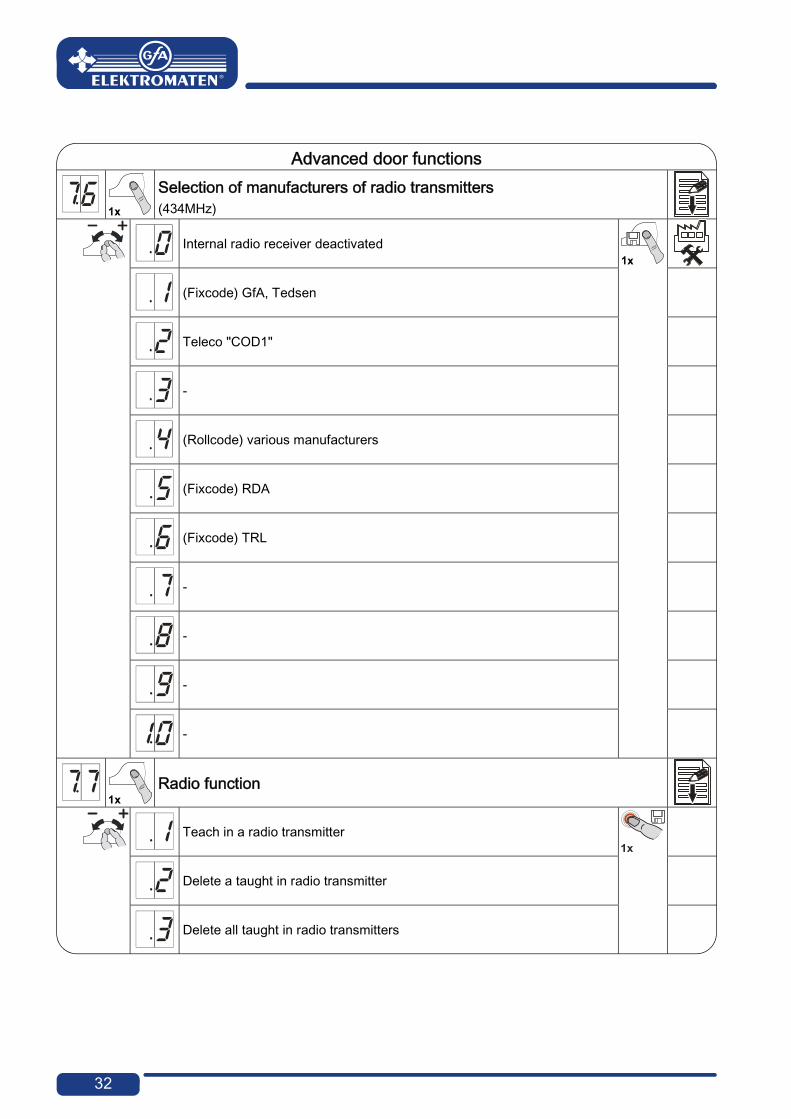
Advanced door functions
Selection of manufacturers of radio transmitters (434MHz)
Internal radio receiver deactivated
(Fixcode) GfA, Tedsen
Teleco "COD1"
-
(Rollcode) various manufacturers
(Fixcode) RDA
(Fixcode) TRL
-
-
-
-
Radio function
Teach in a radio transmitter
Delete a taught in radio transmitter
Delete all taught in radio transmitters

33
Maintenance cycle counter
Maintenance cycle counter
Maintenance cycle preselection
01-99 corresponds to 1,000 to 99,000 cycles Cycles are counted down
Reaction on reaching zero
"CS" display with set value of maintenance cycle
Changeover to hold-to-run and "CS" display with set value of maintenance cycle
Changeover to hold-to-run and "CS" display with set value of maintenance cycle. Pressing the STOP button for 3 sec re-enables 500 automatic cycles

34
Reading out memory
Reading out memory
Cycle counter reading 7-digit number
M HT ZT T H Z E Cycle counter reading in divisions of ten consecutively
M HT
= =
1,000,000100,000
ZT T
==
10,0001,000
HZ
==
10010
E = 1
Last Fault
The six most recent faults are indicated alternately
Data counter 7-digit number
M HT ZT T H Z E Cycle counter reading in divisions of ten consecutively
M HT
= =
1,000,000100,000
ZT T
==
10,0001,000
HZ
==
10010
E = 1
Cycle counter reading of the last programming change
Number of activations for slack-rope, pass-door or crash switch
Firmware version
The firmware version of the control is displayed. In conjunction with DU or FI, additional firmware version of DU or FI.
Delete all setti ngs
Delete
Delete all settings
All (factory setting)! Except for cycle counter

35
Reading out W SD data
Reading out WSD data
WSD data (only with taught in WSD, menu active, lacking data is indicated by "-.-.")
Data indicated alternately 1. Version of master radio module 2. Type of safety edge system 0.0. = none 0.1. = 1k2 0.2. = 8k2 0.3. = optic 3. Door safety switch 0.0. = inactive 0.1. = active 4. Battery voltage 5. Assigned / selected communication channel 6. Signal quality: 0% - 99%
36
9 Safety devices
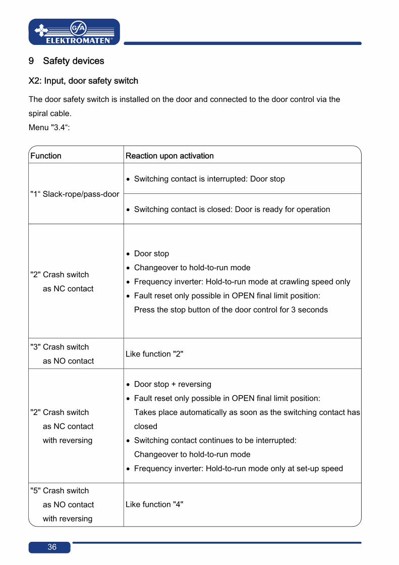
X2: Input, door safety switch
The door safety switch is installed on the door and connected to the door control via the spiral cable. Menu "3.4“:
Function Reaction upon activation
"1“ Slack-rope/pass-door
Switching contact is interrupted: Door stop
Switching contact is closed: Door is ready for operation
"2" Crash switch as NC contact
Door stop Changeover to hold-to-run mode Frequency inverter: Hold-to-run mode at crawling speed only Fault reset only possible in OPEN final limit position:
Press the stop button of the door control for 3 seconds
"3" Crash switch as NO contact
Like function "2"
"2" Crash switch as NC contact with reversing
Door stop + reversing Fault reset only possible in OPEN final limit position:
Takes place automatically as soon as the switching contact has closed
Switching contact continues to be interrupted: Changeover to hold-to-run mode
Frequency inverter: Hold-to-run mode only at set-up speed
"5" Crash switch as NO contact with reversing
Like function "4"

37
Slack-rope/pass-door If the switch is open-circuit when a movement command is given, fault “F1.2” is displayed. If activated during the door movement, the door is immediately stopped and fault “F1.2” is displayed.
Pass-door switch: Entry sense The switch, which has been tested to performance level c (plc) in accordance with EN 13849-1, is monitored by the door control. If the switch is open-circuit when a movement command is given, fault “F1.2” is displayed. If activated during the door movement, the door is immediately stopped and fault “F1.2” is displayed. The magnetic contacts in the switch are switched by a permanent magnet. The door control assesses the switching status of the contacts independently of each other. The “F1.7” fault indication appears if there is a fault.
Crash switch as NC or NO contact The crash switch is activated if the door is pushed out of the guides. If the switching contact is activated, the door is stopped, fault F4.5 is displayed, and a changeover to "hold-to-run" is carried out. The door can be moved only via the integrated push-buttons of the door control. Hold-to-run mode is only possible at crawling speed with frequency inverter operation. The fault "4.5" can only be reset in OPEN final limit position by pressing the STOP push-button of the door control for more than 3 seconds or by switching the mains voltage off and on. Fault "F4.5" will recur, if the switching contact continues to be activated. With the reversing function, a reset is carried out automatically in the OPEN final limit position as soon as the switching contact is closed. Otherwise only hold-to-run mode is possible.

38
X2: Input, safety edge system
The door control automatically detects three different safety edge systems.
Important! Connect safety edge systems in accordance with EN 12978 The hold-to-run mode can always be used should the safety edge system be
defective
1K2 resistor evaluation This safety device is intended for a pneumatic switch with an NC contact connected in series with an end of line resistor of 1K2, +/-5 %, and 0.25 W. If activated, pressure is generated in the rubber profile which activates the pneumatic switch. The safety edge system must be tested in the CLOSE final limit position. The "pre-limit safety edge system" door position test is used for conducting the test. Should the door move past the pre-limit position when it closes, two seconds will start to lapse. Within this time frame pressure must be generated by the safety edge system from it contacting the ground. If the pneumatic switch is not activated, the test has failed (is negative) and the "F2.8" fault indication is displayed. If there is a short circuit in the safety edge system, fault "F2.7" is displayed. Upon activation of the safety edge system or permanent disconnection of the current circuit, the "F2.6" fault indication appears.
8K2 resistor evaluation This safety device is intended for an electrical safety edge system with an end of line resistor of 8k2, +/- 5 % and 0.25 W. If activated, there is a short circuit and fault "F2.4" is displayed. If there is an open circuit, the "F2.5" fault indication appears.

39
Optical safety edge system The functional principle is based on a through-beam photo cell fitted into the leading edge rubber strip. If activated, the light beam is interrupted. Fault “F2.9” is displayed if the safety edge system is activated or faulty.
Installation of the spiral cable
The spiral cable should enter the door control panel from the left- or right-hand side and should be fixed in place with a cable gland. The safety edge system is connected via the 3-pole plug, and the slack-rope or the pass door via the 2-pole plug.
Important! ▶ Check the pre-limit safety edge position At a door opening height > 5 cm, reversing must occur after activation of the
safety edge system
Function of the safety edge system in the pre-limit area Menu "2.1":
Function Reaction upon activation of the safety edge system
"1" Active Stop
"2" Inactive No reaction Door moves to CLOSE final limit position
"3" Ground adjustment (DES) Stop; correction of the CLOSE final limit position at the
next closing
"4" Reversing in the overrun area (DES)
Reversing upwards from the overrun area upon activation of the safety edge system
40
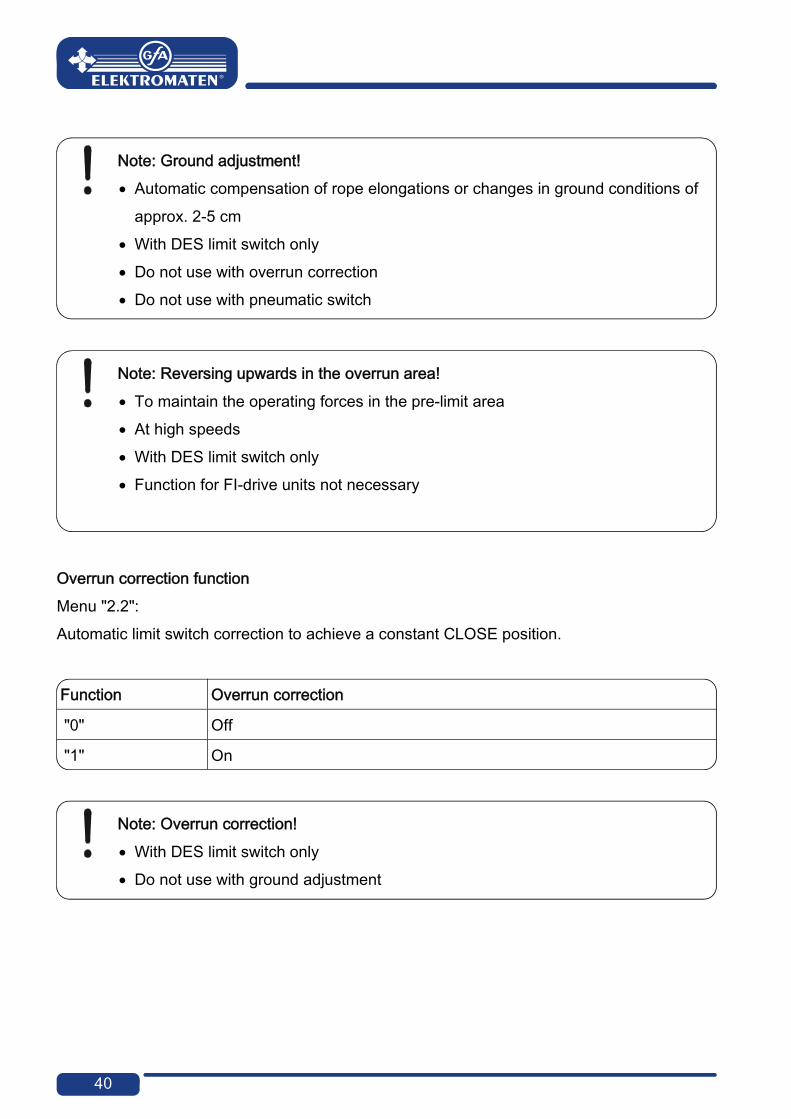
Note: Ground adjustment! Automatic compensation of rope elongations or changes in ground conditions of
approx. 2-5 cm With DES limit switch only Do not use with overrun correction Do not use with pneumatic switch
Note: Reversing upwards in the overrun area! To maintain the operating forces in the pre-limit area At high speeds With DES limit switch only Function for FI-drive units not necessary
Overrun correction function Menu "2.2": Automatic limit switch correction to achieve a constant CLOSE position.
Function Overrun correction
"0" Off
"1" On
Note: Overrun correction! With DES limit switch only Do not use with ground adjustment

41
Reversing function Menu "2.5": Limiting of the number of reversing movements following safety edge system activations via automatic closing. If the set value is exceeded, automatic closing is deactivated and the "F2.2" fault indication is displayed.
Note! To reset fault "F2.2": Move to CLOSE final limit position

42
Integrated "WSD" wireless safety device
For evaluating the safety edge system and/or door safety switch without a spiral cable. For initial operation, see "Teach-in of WSD door module".
Attention – Damage to components! ▶ We recommend providing further protection (protective cover) for the use in car
wash facilities Water additives (e.g. softening agents, surfactants)
lead to brittle and cracked gaskets ▶ Keep the lines short from the "WSD" junction box to plug connections and
terminals ▶ Avoid installing the lines directly above the receiver board ▶ Avoid bending the aerial ▶ Carefully close the cover
Usable safety devices
Safety edge systems 8K2 resistor evaluation Optical safety edge system
(universal or low-power sensors only)
Door safety switch Slack-rope or pass-door switch Crash switch with NC contact

43
Note! ▶ For a description of the safety device and relevant adjustment procedures see X2 Crash switch function as NO contact is hidden If the battery is low, fault indication "F1.9" appears and there is a changeover to
the "hold-to-run" door operating mode Battery is fully discharged: Fault indication "F1.6" is displayed and door
movement is not possible ▶ When performing annual maintenance tasks involving the door system, replace
the "WSD" battery as a precautionary measure
Menu "9.6": Alternating display of "WSD" statuses including Version Type of safety edge system
"0.0." = none "0.1." = 1k2 "0.2." = 8k2 "0.3." = optic
Door safety switch "0.0." = inactive "0.1." = active
Battery voltage Assigned / selected communication channel Signal quality ranging from 0% - 99%

44
EMERGENCY operation
Warning! "Hold-to-run" door operating mode:
The door must be fully visible from the operating point
EMERGENCY operation allows for moving the door to a required position by bypassing faults with the signal transmission of the safety device. EMERGENCY operation is activated after 7 seconds of continuously pressing the STOP push-button and indicated by the flashing display.
Note! The door cannot be moved in case of "F1.3" and "F1.4" fault indications for
reasons of operating safety ▶ Activation of EMERGENCY operation: Use keypad on control to continuously
press the STOP push-button, while simultaneously pressing the OPEN or CLOSE push-button to move the door
X3: Input, emergency stop
Connection of an emergency stop control device as per EN 13850 or an evaluation unit for an anti-trap safety device. The “F1.4” fault indication appears upon activation.
Note! FI-drive units: Drive units are de-energised as a result of an emergency stop

45
10 Functional description
X: 24 V DC voltage supply
Connection of external devices such as photo cell, radio receiver, relay, etc. via the 24 V and GND terminals.
Attention – Damage to components! Total current consumption of external devices: Maximum 350 mA
X1: Mains supply line for control and external supply
Mains supply line for control Connection via terminals X1/1.1 to X1/1.4 and PE. Various mains connections: 3 N~, 3~, 1 N~ for symmetric and asymmetric motors.
Note! ▶ Pay attention to the "Mains supply connection" and "Mains supply connection to
control" descriptions
External supply Connection of external devices for 230 V, such as photo cell, radio receiver, relay, etc. via terminals X1/1.8 and X1/1.9.
Note! Mains supply: 3 N~400 V or 1 N~230 V, symmetric Protection via F1, 1.6-A time-lag micro-fuse

46
X4: Input, automatic closing Off/On
Connection of a switch via terminals X4/1 and X4/2 for switching the automatic closing off and on.
X5: Input, control device
Warning! ▶ "Hold-to-run" door operating mode:
The door must be fully visible from the operating point
Door operating mode "3" allows a place of installation of the control device without sight of the door.
Note! ▶ Application without STOP push-button: Connect wire link X5.1 to wire link X5.2 If the safety edge system or photo cell fails, the control device will not function.

47
X6: Input, "Through / reflective photo cell" or light curtain
Photo cell A photo cell is used for presence detection. It is only active in door operating modes "3" and "4", in the OPEN final limit position or during the closing operation. If the light beam is interrupted, fault indication "F2.1" appears.
Light curtain The light curtain must be self-testing and correspond at least to safety category 2. If the light curtain corresponds to these requirements, the door can close into self-hold without safety edge system.
Important! ▶ Operation without safety edge system: Connect 8K2 resistor via terminals X2/3
and X2/4 ▶ Photo cells must not be used via the UBS system ▶ Do not use menu "3.2" for the light curtain
▶ To test the light curtain, activate relay contact X20 or X21. For a description of the relay functions see menu "2.7" or "2.8". If the light beam is interrupted, fault indication "F4.6" appears. Testing is carried out at each CLOSE command, the contact of the light curtain must switch off within 100 ms. If the test is positive, the contact must switch back on within 300 ms. If the test fails (is negative), fault indication "F4.7" appears. ▶ To reset fault indication "F4.7": Switch control off and on.
Note! ▶ Only use photo cells or light curtains with "Light switching" mode

48
Effect of interrupting the light beam
Door position Effect of interrupting the light beam
CLOSE final limit position No action
Upwards travel No action
OPEN final limit position Without automatic closing
No action
OPEN final limit position With automatic closing
Reset automatic closing
OPEN final limit position With automatic closing and interruption to timer
The door closes 3 seconds after the interruption period for the light beam has ended
Advanced photo cell function Menu "2.4":
Function Advanced photo cell function
"0" No action
"1" Cancel automatic closing
The door closes 3 seconds after the interruption period for the light beam has ended
"2" Vehicle recognition
The door closes after the interruption period for the light beam has ended, if the interruption period is longer than 1.5 seconds
Reset of automatic closing if the interruption duration for the light beam is equal to or less than 1.5 seconds

49
Interruption to photo cell operation Menu "3.2"
Function Interruption to photo cell operation
"0" Off
"1" On
Teach-in mode first active when exiting the program.
Warning! Presence detection is disabled in the teach-in mode
In the teach-in mode, the door must be fully opened and closed twice. The light beam must be interrupted twice at the same door position. The teach-in mode is then terminated. The photo cell has no function below this stored door position.
Teach-in mode display
Upon exiting the program
When the light beam is interrupted for the first time
After the second interruption to the light beam at the same door position, and with the CLOSE final limit position reached
Note! If the teaching in is not successful, open and close the door again, so that two
identical door positions are stored.

50
X7: Input, pull switch/radio receiver
Connection of a pull switch or external radio receiver via terminals X7/1 and X7/2. The switching contact must be potential-free (NO contact).
Pull switch or radio receiver function Menu "2.6":
Pulse type Reaction upon activation
"1" The door CLOSES from the OPEN final limit position or the intermediate
stop position The door OPENS from all other door positions or door movements
"2" OPEN-STOP-CLOSE-STOP-OPEN command sequence
"3" Door always executes OPEN movement

51
Internal radio receiver
The integrated radio receiver can be set for a specific radio transmitter manufacturer via menu "7.6". One or more radio transmitters can be taught or deleted via menu "7.7".
Note! A combination of different radio transmitter manufacturers is possible Only use 434 MHz radio transmitters Up to 64 radio channels can be taught.
Teach-in of radi o tr ansmit ter
Teach-in of radio transmitter1. Select radio transmitter manufacturer's system
2. Activate radio transmitter 3. Teach in
4. Switch to door operation

52
Deleti ng an i ndividual radio transmitter
Deleting an individual radio transmitter1. Activate delete, 10 seconds active 2. Delete
3. Switch to door operation
Deleti ng all radio transmitters
Deleting all radio transmitters1. Delete all channels
2. Switch to door operation

53
X8: Input, intermediate stop On/Off
Connect a switch to terminals X8/1 and X8/2 to activate and deactivate the intermediate stop. Programme the intermediate stop position via menu “1.6”. With an OPEN command, the door moves to the stored door position. When the intermediate stop function is deactivated, the door can move back to the OPEN final limit position.
Intermediate stop function Menu "2.9":
Function Intermediate stop
"1" All command inputs
"2" Intermediate stop via X7 pull switch and internal radio receiver; OPEN final limit position via all other control devices
"3" Intermediate stop via external X5 control device and internal control
device OPEN final limit position via all other control devices
Note! Double command with functions "2" and "3": Priority is given to OPEN final limit
position, independent of command sequence

54
X20 / X21: Potential-free relay contacts
The relay functions are described under menu "2.7" or "2.8".
Attention – Damage to components! Maximum current of 1 A at 230 VAC and 0.4 A at 24 VDC We recommend the use of LED lamps When using light bulbs, these should have power of maximum 40 W and be shock-proof
Force monitoring (DES only)
Menu "3.1": The force monitoring function can only be used with fully balanced doors and drive units with DES switches. It should be able to detect when persons are moving with the door
Warning! The force monitoring is no substitute for safety measures in providing protection
against the trapping hazard
Function Force monitoring
"0" Off
"2" - "10" 2 - low limit value 10 - high limit value
Important! Force monitoring for doors with spring balance only Environmental factors such as temperature or wind load can lead to inadvertent
triggering of force monitoring

55
After exiting programming, the door must carry out a full opening and closing operation in self-hold mode. The force monitoring is a self-learning system which is effective for an opening width range of 5 cm to 2 m (approx.). Slow progressive changes, e.g. gradual reduction of the spring torsion, are compensated automatically. If force monitoring is triggered, only the "hold-to-run" door operating mode is possible and the "F4.1" fault indication is displayed. Resetting occurs when a final limit position for the door is reached.
Travel time monitoring (NES only)
Menu "3.3" The set travel time is automatically compared with the time measured for movement between the final limit positions. If the travel time is exceeded, the "F5.6" fault indication appears. Fault indication "F5.6" is reset by closing the door.
Note! The travel time is set at the factory to 90 seconds Recommended setting value: door travel time + 7 seconds

56
UBS system
The UBS system is a simple pluggable connection technology from GfA. The control devices are connected to the control by a commercially available patch cable and detected automatically.
Note! The UBS devices function in the same way as wired control devices
UBS connec tion
UBS connection
Three push-button Reflective
photo cell External Pull switch
radio receiver
Reversing duration adjustment
Menu "3.8": Shortening the reversing duration will reduce the operating forces. Extending it, on the other hand, will reduce the wear on the door mechanism.

57
Maintenance cycle counter
Menu "8.5": A value between 0 and 99,000, as a multiple of 1000, can be selected for the maintenance cycle setting. The maintenance cycle counter reading is reduced by one each time the Open final limit position is reached. Once the maintenance cycle reaches zero, the setting from menu “8.6” is activated.
Short-circuit/overload display
If there is a short circuit or an overload of the 24 VDC supply voltage, the 7-digit display vanishes.
Display for active "WSD" wireless safety device
If the "WSD" wireless safety device is active, a red point is displayed on the right-hand digit display.

58
Standby function
If there is no fault or command pending, "Standby" is displayed on the control. Standby is active if the automatic closing duration is longer than 60 seconds. Only the left point, or with an active "WSD" both points, is/are displayed.
Execution of the “Standby” function is stopped by issuing a command or by activating the “S” selector switch.
Lighting of the internal control device
Only the command push-buttons which enable a logical next command are illuminated.

59
11 Status display Faults
Faults
Display: "F" and code
Status code Fault description Measures for fault correction
Terminals X2.1 – X2.2 are open. Slack-rope/pass-door contact is open.
Check door safety switch. Check whether the connection cable is connected.
DES safety circuit is open. Emergency manual operation has been activated. Thermal protection of the motor has tripped.
Check emergency manual operation. Check for overload or stalling of the drive unit.
Terminals X3.1 – X3.2 are open. Emergency stop has been activated.
Check emergency stop. Check whether the connection cable is connected.
Faulty “WSD” radio transmission. Change "WSD" door module batteries.
Switch control off and on.
Faulty "Entry sense" switch. Contact resistances are too high. Faulty entry sense installation.
Open and close pass-door. Check resistance. Check pass-door installation.
Entry sense input (X2.1 – X2.2) faulty.
Switch control off and on. Replace control if necessary.
"WSD" door module batteries are too low. Change "WSD" door module batteries.
No safety edge is detected.
Check the wiring of the safety edge system. Check whether the "WSD" is correctly functioning.
Terminals X6.1 – X6.2 are open. Photo cell has been activated.
Check alignment of the photo cell. Check connection cable. Replace photo cell if necessary.
Maximum number of reversing movements for door through safety edge system activation has been reached. (Only with automatic closing)
Obstacles in the door travel path. Check whether the safety edge system is correctly functioning.

60
Faults
Display: "F" and code
Status code Fault description Measures for fault correction
8k2 safety edge system has been activated.
Check whether the safety edge system is correctly functioning. Check whether the connection cable has short-circuited.
8k2 safety edge system is defective.
Check whether the safety edge system is correctly functioning. Check whether the connection cable is connected.
1k2 safety edge system has been activated.
Check whether the safety edge system is correctly functioning. Check whether the connection cable is connected.
1k2 safety edge system is defective.
Check whether the safety edge system is correctly functioning. Check whether the connection cable has short-circuited.
1k2 testing is negative.
Testing is activated in the lower final limit position. Check pre-limit switch (with NES "S5").
"WSD" wireless safety device or optical safety edge system has been activated or is defective.
Check whether the safety edge system is correctly functioning. Check the "WSD" door module.
(DES) OPEN emergency stop switch reached.
In the voltage-free state, move the door back via emergency manual operation.
(NES) OPEN or CLOSE emergency stop switch reached. Emergency manual operation has been activated. Thermal protection of the motor has tripped
Check OPEN/CLOSE emergency stop switch. Check emergency manual operation. Check drive unit for overload or stalling.
(DES) CLOSE emergency stop switch reached.
In the voltage-free state, move the door back via emergency manual operation.
(NES) Faulty activation of the "S5" pre-limit switch.
Check the "S5" pre-limit switch for correct functioning and setting.

61
Faults
Display: "F" and code
Status code Fault description Measures for fault correction
No limit switch detected (active at initial start-up).
Connect the limit switch to the control. Check the limit switch connection cable.
Limit switch system has been changed without resetting the control.
Reset the control via menu "9.5".
Internal plausibility error. Release of failure with next command.
Triggering of force monitoring. Check the door mechanism for stiffness.
Crash detectors (X2.1 – X2.2) have been activated.
Check crash detector or connection cable. Reset error, press STOP button for 3 seconds.
Terminals X6.1 – X6.2 are open. Light curtain has been activated.
Check light curtain. Check whether the connection cable is connected.
Light curtain is defective.
Comply with the light curtain manufacturer's specifications. Check connection cable.
Controller fault. Switch control off and on.
Replace control if necessary.
ROM error. Switch control off and on.
Replace control if necessary.
CPU error. Switch control off and on.
Replace control if necessary.

62
Faults
Display: "F" and code
Status code Fault description Measures for fault correction
RAM error. Switch control off and on.
Replace control if necessary.
Internal control error. Switch control off and on.
Replace control if necessary.
Fault with digital limit switch (DES). Check DES connector and connection cable.
Switch control off and on.
Fault with door movement.
Check the door mechanism for stiffness. Check the limit switches for correct rotational movement. Switch control off and on.
Fault with rotating direction. Change rotating direction via menu "0.2".
Non-permitted door movement in stopped condition.
Release of failure through command. Check brake and drive unit.
Drive unit does not follow specified travel direction.
Release of failure through command. Check for overload of the drive.
DU / FI closing speed is too high. Switch control off and on.
Replace drive unit if necessary.
Internal FI communication failure. Switch control off and on.
Replace FI-drive unit if necessary.
Low voltage in the DC voltage link.
Release of failure through command. Check mains input voltage. Change slope times/speeds.

63
Faults
Display: "F" and code
Status code Fault description Measures for fault correction
Excess voltage in the DC voltage link.
Check mains input voltage. Release of failure through command. Change slope times/speeds.
Temperature limit exceeded.
Check for overload of the drive unit. Cool down the drive unit and reduce the number of cycles.
Permanent current overload.
Check for overload of the drive unit. Check the door mechanism for stiffness or weight.
Brake / FI fault. Check brake, replace if necessary.
If problem recurs, replace drive unit.
FI group message.
Release of failure through command. Replace drive unit if message continues to be displayed.
Minimum travel path not reached during initial operation. Move the door for at least 1 second.

64
Commands
Commands
Display: "E" and code
Code Command description
An Open command is present. Inputs X5.3, X7.2, internal radio system, UBS control device or UBS radio receiver
A STOP command is present. Inputs X5.2, X7.2, internal radio system, UBS control device or UBS radio receiver or simultaneous OPEN and CLOSE commands
A CLOSE command is present. Inputs X5.4, X7.2, internal radio system, UBS control device or UBS radio receiver

65
Status indications
Status indicationsStatus display Description
Preset value for maintenance cycle counter status reached
Dot on left is not lit: control circuit has short-circuited or is overloaded.
Dot on right is lit: internal "WSD" wireless safety device is active.
Function for changing the rotating direction is activated, only possible during initial operation.
Change of rotating direction has been carried out, only possible during initial operation.
Flashing
Emergency operation is active or programming option is blocked.
Flashing
Teach in OPEN final limit position.
Flashing
Teach in CLOSE final limit position.
Flashing
UPWARDS travel active.
Flashing
CLOSING operation active.
Stop between the set final limit positions.
Stop at the OPEN final limit position.
Stop at the intermediate stop position.
Stop at the CLOSE final limit position.
Teaching in or deleting of WSD or radio transmitter confirmed. Blocking of programming option confirmed. Flashing display: Unblocking of programming option active.

66
12 Explanation of symbols
Symbol Explanation
Prompt: Read installation instructions
Prompt: Check
Prompt: Note
Prompt: Note the setting of the program below
Default adjustment of the program
Default adjustment of the program, value on the right
Default adjustment of the minimum limit, dependent on drive unit
Default adjustment of the maximum limit, dependent on drive unit
Setting range
Prompt: Select program or value, turn selection switch left or right
Prompt: View program, press selection switch once
Prompt: Save, press selection switch once

67
Symbol Explanation
Prompt: Setting via OPEN/CLOSE built in push button, open push button: Value upwards; CLOSE button: Value downwards
Prompt: Press stop button once via built in push button
Prompt: Save, press stop button once via built in push button
Prompt: Save, press stop button for three seconds via built in push button
Prompt: Reset the control, press stop button for three seconds via built in push button
Prompt: Move to door positions
Prompt: Move to door positions for OPEN limit switch
Prompt: Move to pre-limit
Prompt: Move to door positions for CLOSE limit switch

68
13 D eclar ati on of Incorporati on/Declar ation of Confor mity
Declaration of Incorporation
pursuant to Machinery Directive 2006/42/EG for a partly completed machine Appendix II Part B GfA - Gesellschaft für Antriebstechnik
Dr.-Ing Hammann GmbH & Co KGWiesenstraße 81
40549 DüsseldorfDeclaration of Conformity pursuant to EMC Directive 2004/108/EC
We, GfA – Gesellschaft für Antriebstechnik,
hereby declare that the product specified in the following complies with the above-mentioned EU Directive and is only intended for installation in a door system.
TS 971 Applied standards DIN EN 12453 DIN EN 12978 DIN EN 60335-1 DIN EN 61000-6-2 DIN EN 61000-6-3
Industrial, commercial and garage doors and gates Safety devices for power operated doors and gates Household and similar electrical appliances - Safety – Part 1: General requirements Electromagnetic compatibility (EMC) - Part 6-2 Generic standards - Immunity for industrial environments Electromagnetic compatibility (EMC) - Part 6-3 Generic standards - Emission standard for residential, commercial and light-industrial environments
We undertake to transmit, in response to a reasoned request by the authorities, the special documents for this partly completed machine.
Authorised representative for the compilation of the technical documentation
(EU address in the company)
Dipl.-Ing. Bernd Synowsky Documentation representative
Partly completed machinery according to EC Directive 2006/42/EC is only intended to be installed in, or combined with, other machinery (or other partly completed machinery/systems) in order to form a completed machine pursuant to the Directive. This product must therefore only be put into operation when it has been determined that the complete machine/system in which it has been
installed complies with the provisions of the above-mentioned directives.
Düsseldorf, 05.12.2011 Stephan Kleine Managing Director Signature