eleg3923 microprocessor ch.10 serial port...
TRANSCRIPT

Department of Electrical EngineeringUniversity of Arkansas
ELEG3923 MicroprocessorCh.10 Serial Port Programming
Dr Jingxian WuDr. Jingxian [email protected]

2
OUTLINE
• Basics of Serial Communication
• Serial port programming in Assembly
• Programming the second serial port• Programming the second serial port
• Serial port programming in C

SERIAL COMMUNICATION3
• Serial communication v.s. parallel communication– Computer transfer data in two ways: parallel, serial– Parallel communication
• 8 or more parallel lines are used to transfer data• 8 or more parallel lines are used to transfer data– E.g. connecting 8051 to LCD, data bus, connecting to hard drive
• More data can be transferred in unit period of time • Usually used for short distance data transfer y
– Long parallel wires function like antenna, and will leak signal during Tx– The leaked signals will cause mutual interference for signals in wire (cross-talk)
– Serial communication• Use 1 data line to transfer data
– Data is transmitted 1 bit a time• Usually used for data transfer over longer distance

SERIAL COMMUNICATION: DUPLEX4
• Simplex, Half-duplex, and full-duplex– Simplex: communication can occur in only one direction (A � B)
• E.g. pager, broadcast radio– Half-duplex: communication can happen in both directions, but only one at a
time (A � B, or B � A, but not simultaneously)• E.g. Police radio (walki-talki)
l h l (d li ) i h• Only 1 channel (data line) is enough– Full-duplex: communication can happen in both directions simultaneously
• E.g. telephone• Two channels (data lines) are required.• Full-duplex = two simplex

SERIAL COMMUNICATION: ASYNCHRONOUSA h i l i ti
5
• Asynchronous serial communication– Data is transmitted in bursts without following a specific clock
• Data can be transmitted at any time.• Synchronous transmission: data can only be transmitted at special instants
– When there is no data, channel remains constant to indicate “idle” (no information). • e.g. some system use “high” voltage to indicate idle• How does the receiver tell the difference between “idle” and “11111111”?
– Framing• Data characters are placed between start and stop bits• Start bit: 1 bit (e.g. low)• Stop bit: 1 bit (e.g. high), or, 2 bits (e.g. high, low)• E.g. 8-bit ASCII + 1 start bit + 1 stop bit = 10 bits/frame

SERIAL COMMUNICATION: TRANSFER RATE6
• Transfer rate– Bit rate
• Number of bits that can be transferred in unit time (1 second)• Unit: bps (bit per second), Kbps (kilo-bit per second), Mbps (mega-bit per
second), Gbps (Giga-bit per second), Tbps (Terra-bits per second)– Terminology conventions
( i i di k i )• For storage space (RAM size, ROM size, disk size)– 1 kilo = 2^10, 1 mega = 1^20, 1 giga = 1^30
• For data rate– 1 kilo = 1,000, 1 mega = 1,000,000, 1 giga = 1,000,000,000
– Baud rate• The number of symbols that can be transferred in unit time (1 second)• For some systems, 1 symbol = 1 bit, for some other systems, 1 symbol
can be used to represent multiple bits (e.g. 1 symbol = 8 bits)
SERIAL COMMUNICATION: STANDARD7
• Communication standard– A set of rules that must be followed by communication devices
• To ensure that communication devices from different manufactures can i i h h hinteroperate with each other
– Example rules:• Which voltage used to represent ‘0’, which voltage used to represent ‘1’
bi h bi• How many start bits, how many stop bits• Which voltage(s) used for start bits, which voltage(s) used for stop bits• How many bits in one frame (7 bits, 8 bits, 10 bits, …)• The format of control signals, how many control pins
– Example standards• RS232, IEEE 802.11 (WiFi), IEEE 802.16 (WiMax), WCDMA, ……
• RS232– The most popular serial communication standard– Developed by Electronics Industries Association (EIA) in the 1960s’– Still widely used today

SERIAL COMMUNICATION: RS2328
• DTE v.s. DCE– DTE: data terminal equipment (e.g. PC)– DCE: data communication equipment (e.g. modem, switch, router, and other
i i d i )communication device)– DTE and DCE have different pin definitions
• RS232 connectors– DB-25 25-pin connector– DB-9 9-pin connector– Pin definition for DTE
• We can either use all 9 pins, or just use3 pins: TxD, RxD, GND
• TxD: transmit data• RxD: receive data• GND: signal ground• The remaining pins are for more
sophisticated conrols
SERIAL COMMUNICATION: RS2329
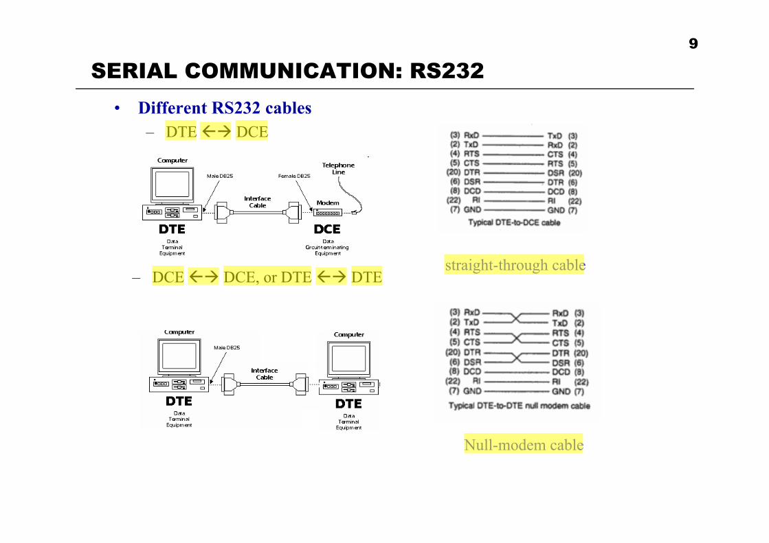
• Different RS232 cables– DTE �� DCE
straight-through cable– DCE �� DCE, or DTE �� DTE
N ll d blNull-modem cable

SERIAL COMMUNICATION: RS23210
• Signal level of RS232– ‘1’ is represented by -3 to -25 V– ‘0’ is represented by +3 to +25 V– They are not TTL (transistor-transistor logic) compatible. In TTL
• ‘1’: 2.2 to 5 V• ‘0’: 0 to 0.8 V
– 8051 is TTL compatible: • 8051 and RS232 devices cannot be directly connected together!
• MAX232– A voltage converter (line driver) that can convert RS232 signal to TTL
voltage level– 1 MAX232 chip can be used
to drive 2 RS232 ports
11
OUTLINE
• Basics of Serial Communication
• Serial port programming in Assembly
• Programming the second serial port• Programming the second serial port
• Serial port programming in C

ASSEMBLY: 8051 AND UART12
• 8051– Most 8051 has 1 serial port
• P3.0 (RXD0), P3.1 (TXD0)– DS89C4x0 has 2 serial ports
• P1.2 (RXD1), P1.3 (TXD1)• P3.0 (RXD0), P3.1 (TXD0)
• UART– Universal asynchronous receiver transmitter– An integrated circuit commonly used in conjunction with RS232
• It’s built inside 8051• The circuit can interpret communication command
– When an ASCII code is sent to UART, it will automatically add start and stop bits before transmit it through serial port
– When receiving data from serial port, UART will automatically detect start bit and stop bit, remove the start and stop bits from the
i d d t d d th d t t th CPUreceived data, and send the pure data to the CPU– UART saves us from the details of communication standards.
ASSEMBLY: BAUD RATE AND TIMER13
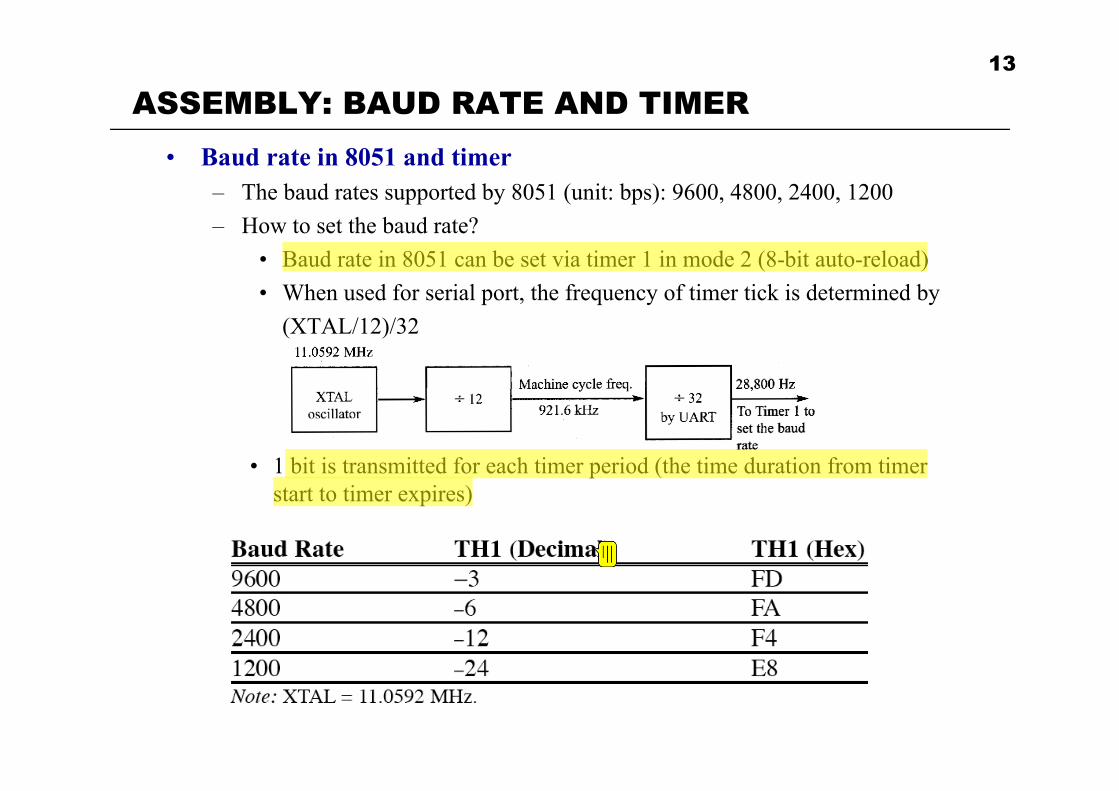
• Baud rate in 8051 and timer– The baud rates supported by 8051 (unit: bps): 9600, 4800, 2400, 1200– How to set the baud rate?
• Baud rate in 8051 can be set via timer 1 in mode 2 (8-bit auto-reload)• When used for serial port, the frequency of timer tick is determined by
(XTAL/12)/32
• 1 bit is transmitted for each timer period (the time duration from timer start to timer expires)

ASSEMBLY: BAUD RATE AND TIMER14
• Calculation of baud rate– With XTAL = 11.0592, find the TH1 value needed to have the baud rate 9600
• Clock frequency of timer clock: f = (11.0592 MHz / 12)/32 = 28,800Hz• Time period of each clock tick: T0 = 1/f = 1/28800• Duration of timer (1 timer cycle): (# of clock ticks in timer)*T0• 9600 baud � duration of 1 symbol: 1/9600�1 timer cycle: 1/9600• 1/9600 = 1/f * (# of clock ticks in timer)• # of clock ticks in timer = f/9600 = 28800/9600 = 3 � TH1 =-3• Similarly, for baud 2400
– # of clock ticks = f/2400 = 12 � TH1 = -12• Example: set baud rate at 9600
MOV TMOD, #20HMOV TH1 # 3MOV TH1, #-3SETB TR1……
– When connecting two devices through serial port, both devices must have the same baud

ASSEMBLY: BAUD RATE AND TIMER15
• Example– If the value in TH1 is B8, find the baud rate of the serial port (XTAL =
11.0592MHz)

ASSEMBLY: REGISTERS16
• SBUF register (Serial buffer)– An 8-bit register used for serial communication– It holds the data to be transferred or received from serial port.– E.g. to send ‘D’ to serial port: MOV SBUF, #’D’
• The data in SBUF will be automatically processed by UART, then sent to serial port (e.g. pin TXD0)
i d f i l– E.g. to receive data from serial port: MOV A, SBUF• Once UART receives data from serial port (e.g. pin RXD0), it will strip
the start and stop bits and then put the data in SBUFIt b ff b t CPU d i l t– It serves as a buffer between CPU and serial ports
• SCON register (Serial control register)– An 8-bit register used to program the start bit, stop bit, and data bits of data
framing and some other serial related processingframing, and some other serial related processing

ASSEMBLY: REGISTERSSCON i t
17
• SCON register
– SM0, SM1 (serial port mode)( p )• Specify framing format, how to calculate baud• (SM0, SM1) = (0,1), mode 1: 8-bit data, 1 start bit, 1 stop bit, variable
baud set by timer. Most commonly usedTh th th d l d ( t i d f thi )• The other three modes are rarely used (not required for this course)
– (SM0,SM1) = (0,0), mode 0: fixed baud = XTAL/12– (SM0, SM1) = (1,0), mode 2: 9-bit data, fixed baud– (SM0 SM1) = (1 1) mode 3: 9-bit data variable baud– (SM0, SM1) = (1, 1), mode 3: 9-bit data, variable baud
– SM2 • SM2 = 0: single processorg p• SM2 = 1: multiprocessor communication (not required for this course)

ASSEMBLY: REGISTERSSCON i t
18
• SCON register
– REN (Receive Enable)( )• Enable/disable reception• REN = 1: the 8051 will accept incoming data from serial port• REN = 0: the receiver is disabled• E.g. SETB REN, CLR REN, SETB SCON.4, CLR SCON.4
– TB8• Used by modes 2 and 3 for the transmission bit 8 (the 9th data bit)
CLR TB8 h i d 1• CLR TB8 when using mode 1– RB8
• Used by modes 2 and 3 for the reception of bit 8 (the 9th data bit)• Used by mode 1 to store the stop bitUsed by mode 1 to store the stop bit

ASSEMBLY: REGISTERSSCON i t
19
• SCON register
– TI (transmit interrupt)( p )• When 8051 finishes the transfer of the 8-bit character, it set TI to ‘1’ to
indicate that it is ready to transfer the next character• The TI is raised at the beginning of the stop bit
RI ( i i t t)– RI (receive interrupt)• When 8051 receives a character
– 1. The UART removes start bit and stop bit– 2 The UART puts the 8-bit character in SBUF– 2. The UART puts the 8-bit character in SBUF– 3. RI is set to ‘1’ to indicate that a new byte is ready to be picked up
in SBUF• RI is raised halfway through the stop bit

ASSEMBLY: TRANSMISSION PROGRAM20
• Example– Write a program to transfer letter “A” serially at 4800 baud, continuously
MOV TMOD, #20H ; timer 1, mode 2 (8-bit auto-reload)MOV TH1, #-6 ; 4800 baudMOV SCON, #50H ; 0101 0000 (mode 1, single
; processor,REN=1)iSETB TR1 ; start timer
AGAIN: MOV SBUF, #’A’ ; store ‘A’ in SBUFHERE: JNB TI, HERE ; wait for TI = 1 (transmission over)
CLR TI ; clear TI for next transmissionSJMP AGAIN ; repeat
– The data in SBUF is transmitted serially, one bit at a time• If we write a new character to SBUF before TI is raised (the transmission of
the previous character is not over yet), part of the original data will be lost
ASSEMBLY: TRANSMISSION PROGRAME l
21
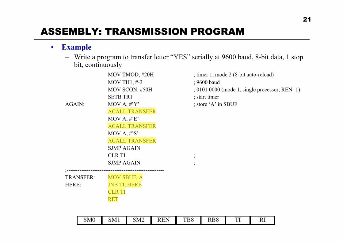
• Example– Write a program to transfer letter “YES” serially at 9600 baud, 8-bit data, 1 stop
bit, continuously MOV TMOD #20H ; timer 1 mode 2 (8-bit auto-reload)MOV TMOD, #20H ; timer 1, mode 2 (8-bit auto-reload)MOV TH1, #-3 ; 9600 baudMOV SCON, #50H ; 0101 0000 (mode 1, single processor, REN=1)SETB TR1 ; start timer
AGAIN: MOV A, #’Y’ ; store ‘A’ in SBUFAGAIN: MOV A, # Y ; store A in SBUFACALL TRANSFERMOV A, #’E’ACALL TRANSFERMOV A, #’S’ACALL TRANSFERSJMP AGAINCLR TI ; SJMP AGAIN ;
;-----------------------------------------------------TRANSFER: MOV SBUF, AHERE: JNB TI, HERE
CLR TIRET

ASSEMBLY: RECEPTION PROGRAM22
• Example– Program the 8051 to receive bytes of data serially, and put them in P1. Set the
baud rate at 4800, 8-bit data, 1 stop bitMOV TMOD #20HMOV TMOD, #20HMOV TH1, #-6 ; 4800 baudMOV SCON, #50H ; mode 1SETB TR1
HERE: JNB RI, HERE ; wait for char to come in (RI=1)MOV A, SBUF ; save incoming byte in AMOV P1, A ; send to port 1CLR RI ; clear, get ready for next byteSJMP HERE
– RI = 1 indicates a new byte is copied in SBUF– We need to copy the data in SBUF to another place immediately after RI = 1
• Otherwise the contents in SBUF will be overwritten by the next character

ASSEMBLY: TRANSMISSION AND RECEPTION23
• Example– Write a program to (1) send to PC “We are ready”; (2) receive data from PC
and send it to P1; (3) read data from P2 and send it to PC. (2) and (3) should be performed continuouslybe performed continuously.

ASSEMBLY: TRANSMISSION AND RECEPTION24
• Example (Cont’d)

ASSEMBLY: DOUBLE BAUD RATETh b d t b d bl d b i th PCON i t
25
• The baud rate can be doubled by using the PCON register– PCON: (Power control)
– SMOD = 1: double the baud generated by crystal and/or timer– SMOD = 0: the baud is determined by crystal and/or timer– NOT bit addressable!– How to set SMOD?
• Use register A as an intermediate register
MOV A, PCONSETB ACC.7 ; A.7 is invalid!MOV PCON, A
ASSEMBLY: EXAMPLES26
• Example– Find the baud rate if TH1 = -2, SMOD = 1, XTAL = 11.0592 MHz
– Write a program to use serial port with baud 19200. (1) read a byte from serial ( ) if h b i i b k i l ( ) if h b iport. (2) if the byte is ‘A’, write ‘1’ back to serial port (3) if the byte is not
‘A’, write ‘0’ back to serial port
27
OUTLINE
• Basics of Serial Communication
• Serial port programming in Assembly
• Programming the second serial port• Programming the second serial port
• Serial port programming in C
SECOND PORT28
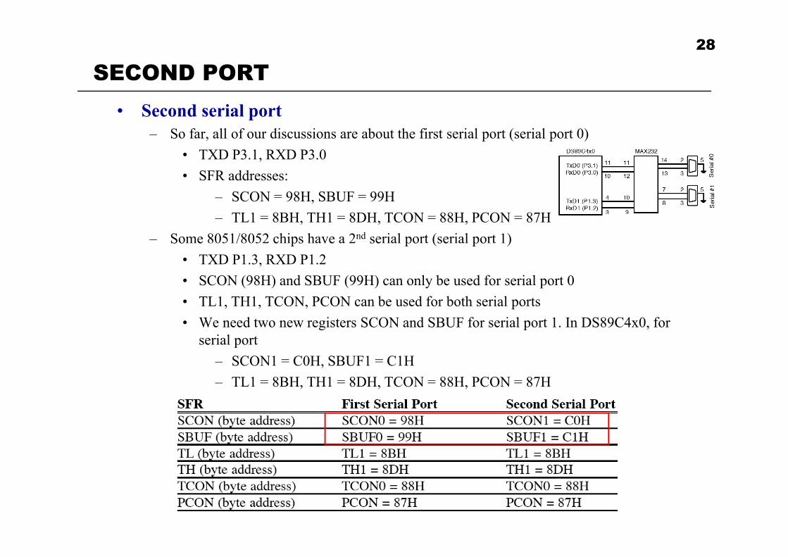
• Second serial port– So far, all of our discussions are about the first serial port (serial port 0)
• TXD P3.1, RXD P3.0SFR dd• SFR addresses:
– SCON = 98H, SBUF = 99H– TL1 = 8BH, TH1 = 8DH, TCON = 88H, PCON = 87H
– Some 8051/8052 chips have a 2nd serial port (serial port 1)So e / c ps ve se po (se po )• TXD P1.3, RXD P1.2• SCON (98H) and SBUF (99H) can only be used for serial port 0• TL1, TH1, TCON, PCON can be used for both serial ports• We need two new registers SCON and SBUF for serial port 1. In DS89C4x0, for
serial port – SCON1 = C0H, SBUF1 = C1H– TL1 = 8BH TH1 = 8DH TCON = 88H PCON = 87HTL1 8BH, TH1 8DH, TCON 88H, PCON 87H

SECOND PORT: EXAMPLEE l
29
• Example– Write a program for the second serial port to continuously transfer “A” at
4800 baudSBUF1 EQU 0C1H ; address for 2nd SBUFSBUF1 EQU 0C1H ; address for 2 SBUFSCON1 EQU 0C0H ; address for 2nd SCONTI1 BIT 0C1H ; bit address of 2nd TI1RI1 BIT 0C0H ; bit address of 2nd RI1
MOV TMOD, #20H ; use timer 1MOV TH1, #-6 ; 4800MOV SCON1, #50HSETB TR1
AGAIN: MOV A, #’A’ACALL SENDCOM2SJMP AGAIN
;----------------------SENDCOM2:
MOV SBUF1, A ; SBUF1HERE: JNB TI1, HERE ; TI1
CLR TI1RET

SECOND PORT: EXAMPLE30
• Example– A switch is connected to P2.0. (1) if SW=0, send “Hello” to serial port 0. (2)
if SW = 1, send “Goodbye” to serial port 1. 9600 baud. RequirementsA i b i SENDCOM0 SENDCOM1• A. write subroutines: SENDCOM0, SENDCOM1
• B. Store “Hello” and “Goodbye” in ROM. Both strings are terminated by 0
• C Use directives• C. Use directives.SBUF1 EQU 0C1H ; address for 2nd SBUFSCON1 EQU 0C0H ; address for 2nd SCONTI1 BIT 0C1H ; bit address of 2nd TI1;RI1 BIT 0C0H ; bit address of 2nd RI1
31
OUTLINE
• Basics of Serial Communication
• Serial port programming in Assembly
• Programming the second serial port• Programming the second serial port
• Serial port programming in C

C PROGRAMMINGE l
32
• Example– Write an 8051 C program to receive a byte of data from serial port 0, then
send it back to serial port 0. Do this continuously.#include <reg51 h>#include <reg51.h>void SerTx(unsigned char);void SerRx(unsigned char *);void main(void){{
char byteBuf;TMOD = 0x20; // timer 1, 8-bit auto-reloadTH1 = 0XFD; // or: TH1 = -3, 9600 baudSCON = 0x50;TR1 = 1; // start timerwhile(1){{
SerRx(&byteBuf); // read byte from serial portSerTx(byteBuf); // send byte back to serial port
}}

C PROGRAMMING33
• Example– (Cont’d)
void SerTx(unsigned char x){
SBUF = x; // put the char in SBUF registerwhile(TI = =0); // wait until transmittedTI = 0;
}
void SerRx(unsigned char * pX)( g p ){
while(RI = =0); // wait until receivedRI = 0;*pX = SBUF; // copy the data in SBUF to (pX)pX SBUF; // copy the data in SBUF to (pX)
}

C PRGRAMMINGE l
34
• Example– Write a C program to transmit a letter ‘A’ serially at 4800 baud continuously.
Use the 2nd serial port with 8-bit data and 1 stop bit.#include <reg51 h>#include <reg51.h>sfr SBUF1 = 0xC1;sfr SCON1 = 0xC0;sbit TI1 = 0xC1;
id i ( id)void main(void){
TMOD = 0x20; // timer 1, mode 2TH1 = 0XFA; // timer 1SCON1 = 0x50; // SCON1 for 2nd serial portTR1 = 1; // start timer 1while (1){{
SBUF1 = ‘A’; // SBUF1 for 2nd serial portwhile(TI1 == 0); // TI1 for 2nd serial portTI1 = 0;
}}