electrowagnetcs of transfor i oem noum … · i. contoli..ng office name6 ano aoress unclassified...
TRANSCRIPT
IT 15 N AT UftUAIA ELECTROWAGNETCSINVCSTZSATbON OF TRANSFOR ICHIGMOUS FOR SOLVIN"O ELECTi
7APR 81 S V LEE, A MITYRA. w L KO NOOOIR6-75-CwUNCLASSIFIED ZMI
1 2*mmI OEM
NOumEh0.mohiiiiimEOm."'.

TECHNICAL REPORT NO. 81-3
April 1981 -
tj
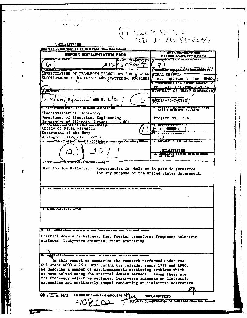
INVESTIGATION OF TRANSFORM TECHNIQUES FOR SOLVING
ELECTROMAGNETIC RADIATION AND SCATTERING PROBLEMS
Final Report D T ICELECTE
S. W.Lee orn e9B~R. MittraW. L. Koo 0v
LU
ELECTROMAGNETICS LABORATORY SUPPORTED BYDEPARTMENT OF ELECTRICAL ENGINEERING CONTRACT NO. NOC014-75-C-0293ENGINEERING EXPERIMENT STATION OFFICE OF NAVAL RESEARCHUNIVERSITY OF ILLINOIS AT URBANA-CHAMPAIGN DEPARTMENT OF THE NAVYURBANA, ILLINOIS 61801 ARLINGTON, VIRGINIA 22217
81 10 14
1,t4CWASIFIEDSIRCURITY CLASSIFICATION or rmis PAGE (when Do*. sng.w.E) _________________
REPORT DOCMENTATION PAGE BEFORE COMPLETING FORMMM3 vT ACCEISM00 VIIENT'S CATALOG MU1111af
tINVESTIGATION OF 51ANSFORM JECHNIQUES FOR WOLVING kFINA REPORT/tLECTR(O(AGNETIC RADIATTON A!ND CATTERING ?JtOBLE(S 1 a07~3 e 8-
-4111 -INU9TRTaueG04 ONG. 111PORN* lUmeR
S. W/Lae 4 ,RJlittra,""a W. LfKo ~ I 5 9 0l4-75-CX293'
3. ERPRUIG LGANIZATIOM MAHE ANO ADDRESS 10. PROGRAM ELEMEMY. PROJECT. TASKr AREA A WORK UNIT NuUMNSElectromagnetics LaboratoryDepartment of Electrical Engineering Project No. N.A.
I. CONTOLI..NG OFFICE NAME6 ANO AORESS
UNCLASSIFIEDIS&. 01C~~SJCO OMRO
Distribution Unlimited. Reproduction in whole or in part is permittedV for any purpose of the United States Governmzent.
17, DIST 1111UTIOM ST ATEMENT ?(o tho .b8treet "fted In 980.5k 30. Of Wtfil"O~ h000 ASPe)
1S. SUPOLEMEINTA11Y MOTES
it Key WON*$ fCentgA...oem evoe. e a* d 06464ey and #40Vt W~ 60esS WIt)
Spectral domain techniques; fast Fourier transform; frequency selectricsurfaces; leaky-wave antennas; radar scattering
30 AORACT fCoifM MI t*-w** 58*88i "*t6#oWl ld Id"*iIP 6V NeeS iW
In this report we sumnarize the research performed under theOM~ Grant N00014-75-C-0293 during the calendar years 1979 and 1980.We describe a number of electromagnetic scattering problem whichwe have solved using the spectral domain methods. Among these arethe frequency selective surfaces, leaky-wave antennas on dielectricwaveguides and arbitrarily shaped conducting or dielectric scatterers.
L/3 ~577SC.SYY CL.AIUC&TWN 00 T-11111 VA4 (MAP WHOM-sed

UILU-ENG-81-2544
Electromagnetics Laboratory Report No. 81-3
INVESTIGATION OF TRANSFORM TECHNIQUES FOR SOLVING
ELECTROMAGNETTC RADIATION AND SCATTERING PROBLEMS II
Accession ForFinal Report NTIS GRA&I
DTIC TABUnannouncedJustificatio
S. W. Lee Listribution/
R. Mittra Availability CodesW. L. Ko Avail and/or
Di- I Special
April 1981
Office of Naval Research
Department of the NavyArlington, Vi:ginia 22217
Contract No. N00014-75-C-0293
Zlectromagnetics LaboratoryDepartment of lectrical Engineering
Engineering Expe luent StationUniversity of Illinois a& Urbana-Champaign
Urbana, Illinois 61801
A
ABSTRACT
In this report we summarize the research performed under the
ONR Grant N00014-75-C-0293 during the calendar years 1979 and 1980.
We describe a number of electromagnetic scattering problems which
we have solved using the spectral domain methods. Among these are
the frequency selective surfaces, leaky-wave antennas on dielectric
waveguides and arbitrarily shaped conducting or dielectric scatterers.
VV
A4-A
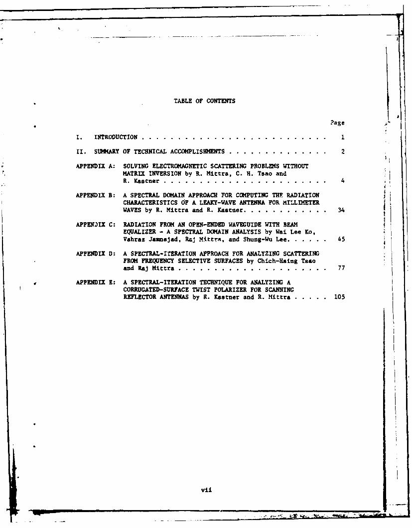
TABLE OF CONTENTS
?age
I. INTRODUCTION . . . . . . . . . . . . . . . . . . . . . . . . . . 1
II. SUMMARY OF TECHNICAL ACCOMPLISHMENTS ....... .............. 2
APPENDIX A: SOLVING ELECTROMAGNETIC SCATTERING PROBLDS WITHOUTMATRIX INVERSION by R. Mittra, C. H. Tsao andR. K stner ........ ........................... 4
APPENDIX B: A SPECTRAL DOMAIN APPROACH FOR COMPUTING THE RADIATIONCHARACTERISTICS OF A LEAKY-WAVE ANTENNA FOR MILLIMETERWAVES by R. Mittra and R. Kastner .... ............ ... 34
APPERJIX C: RADIATION FROM AN OPEN-ENDED WAVEGUIDE WITH BEAMEQUALIZER - A SPECTRAL DOMAIN ANALYSIS by Wai Lee Ko,Vahraz Jamnejad, Ra MittrA, and Shung-Wu Lee ......... 45
APPENDIX D: A SPECTRAL-ITERATION APPROACH FOR ANALYZING SCATTERINGFROM FREQUENCY SELECTIVE SURFACES by Chich-Hsing Tsaoand Raj Mittra. ........ .................... ... 77
APPENDIX E: A SPECTRAL-ITERATION TECHNIQUE FOR ANALYZING ACORRUGATED-SURFACE TWIST POLARIZER FOR SCANNINGREFLECTOR ANTENNAS by R. Kastner and R. Hittra. ........ 105
vii

I. INTRODUCTION
This research effort was to develop new approaches to solving electro-
magnetic and acoustic scattering problems in frequency regimes and for
geometrical configurations, for which the conventional numerical or
asymptotic techniques are found to be inadequate, inefficient and/or
inaccurate. Rather than employ either the matrix metod or the ray
techniques, which are typically valid in the low- ane " gh-frequency
regimes respectively, we investigate the application of the FFT algorithm
in the spectral or ransform domain. Two different variations of the
method have been studied. The first of these employed asymptotic
solutions, such as those based on the Physical Optics or GTD methods, as
initial approximations for an iterative procedure for constructing the
solution to the scattering problem. The second version of the spectral
techniqu. e utilized the variational principle and developed a procedure
called the spectral-Galerkin method. The end result of the application
of the latter method is a matrix equation for the coefficients of the
expansion functions used to repr.4nt the nknown field. Typically, the
size ef this matrix is much smaller Lhan the one obtained via conventional
procedures. Our objectives were to investigate these spectral domain
techniques in great detail and to evaluate the scope and limitations of
the two approaches.
I

II. SUMMARY OF TECHNICAL ACCOMPLISHMENTS
During the last grant period, we have carried out an extensive
investigation of the spectral-Galerkin and spectral iteration techniques
and have applied them to the problem of analyzing a number of electromagnetic
radiation and scattering problems. We have applied the spectral approach
to the problem of scattering by frequency selective surfaces (FSS) which
find widespread use in radomes, reflector antennas, and optical filters.
The spectral iteration technique has been found useful in the low and inter-
mediate frequency ranges where the cell size or the period of the FSS, which
comprises a screen with periodic perforations, is on the order of two
wavelengths or less. Beyond this limit, the spectral-iteration technique
is more efficient as it avoids matrix. inversion altogether and derives
the solution to the integral equation using an iterative procedure. Using
these two methods, we have successfully analyzed several different versions
of FSS and have compared the results with theoretical and experimental
data published elsewhere. The results derived with the spectral approach
have not only been found to be accurate and efficient, but are also applicable
in a frequency range which is considerably wider than that of the conventional
method.
The spectral iteration approach has also been found useful for
analyzing other utuctures, such as conducting and dielectric scatterers
of arbitrary shape. To-date, only a preliminary investigation of this
problem has been carried out but the results appear to be quite encouraging.
An invited paper describing the spectral technique was recently presented
at the Method of Moments Workshop held in St. Cloud, Florida, under the
auspices of Rome Air Development Center. A paper describing this
2
1~.~~~A
presentation is appended herewith (Appendix I). Other manuscripts accepted
for Journal publication and describing the work carried out with partial
support from this grant are also attached.

APPENDIX A
SOLVING ELECTROMAGNETIC SCATTERING PROBLEMS
WITHOUT MATRIX INVERSION
R. Mittra, C. H. Tsao and R. KastnerElectromagne tics LaboratoryUniversity of Illinois
Urbana, IL 61801
Abstract - The applications of the Moment Method a la Harrington
to the solution of electromagnetic scattering and radiation problems
are well known, and the method has revolutionized the way boundary-
value problems are being solved today on modern computers. However,
as the frequency becomes higher and the body size becomes comparable
to the wavelength of the incident field, the CPU time on the computer
becomes large and the storage requirements also become large - if not
prohibitive. It is therefore useful to look for alternative approaches
to the moment method for atticking the radiation and scattering prob-
lems in the so-called resonanci region and above.
In this paper, we introduce an iterative technique in the spectral
domain which circumvents the limitations of the moment method alluded
to above. The method is computationally efficient because it makes ex-
tensive use of the FFT algorithm to perform the Fourier transformation,
which is an integral part of the spectral domain approach. The pro-
cedure also has the un" ,ue feature that it has built-in convergence and
accuracy checks, features which are not typically found in other methods.
The paper illustrates the application of the spectral-iteration tech-
nique using scattering from periodic structures and arbitrary bodies as
examples.
The work was supported by the Office of Naval Research, Contract
!00014-75-C-0293.
4

I. INTRODUCTION
The purpose of this paper is to describe an approach called the
* spectral-iteration technique for solving electromagnetic scattering
problems without the need for matrix inversion. The method is espe-
cially suited in the high frequency range where the dimensions of
structure are large compared to the wavelength. If the moment method
were applied in this range, the matrix size that would be required to
handle such structures would be large, and the matrix inversion time
as well as the storage cost would be prohibitive. Also, there are
geometries such as grating structures which we will be discussing
shortly, for which no asymptotic solutions are available because the
ray solutions based on GTD, or physical optics approximations, are
entirely inadequate.
Although the spectral.-iteration technique has recently been
applied to a wide class of problems,* for the sake of illustrating
the principles of the method we will use the example of periodic
structures such as arrays of conducting strips or periodically per-
forated screens which can be either free-standing or printed on
dielectric substrates (see Figure 1). These gratings have frequency
selective properties, ahd find many applications as artificial die-
lectrics, optical and quasi-optical devices, and dichroic surfaces
for antenna reflectors and radomes.
Conventionally, the problem of electromagnetic scattering from
these periodic structures is attacked using the mode-matching pro-
cedure employed in conjunction with the method of moments. A de-
scription of this procedure can be found in a number of papers on the
subject by Chen (1], Lee (21, and McPhadran and Maystre (3]. Though
this method works quite well i.n the lw-frequency region, it becomes
prohibitively costly if not impractical at the high frequency region
where the aperture size is one to two wavelengths, or larger, because
For a bibliography on Spectral Domain Methods refer to theAppendix.
5

(NCIDENT DIELEC TRC r-METALFIELO SUIBSTRATEc STRIPS
SUBSTR ATEI
(a) Side view (b) Top view[
Fiaur* 1. Freauencv seleotive s.nvfnAr

the matrix size required for an accurate solution bacomes prohibi-
tively large and rt numerical computation becomes extremely time-
conz -sing and costly. As mentioned earlier, the high frequencytechniques, e.g., GTD, cannot be applied to circumveit the aboie
difficulty either, because the complex geometrical configuration
of the structure does not lend itself to the ray fo-malism of GTD.
In this paper we introduce a new technique based on the spectral
domain approach which provides an efficient and accurate solution
to the grating problems described in this paper.
As a first step, the new approach begins with the formulation
of the problem in terms of an integral equation in the transform
domain. The standard procedure for deriving the integral equation
for the unknown aperture field (or the induced current) is still
followed; however, in the transform domain the convolution form of
the integral equation becomes an algebraic one. Furthermore, be-
cause of the periodic nature of the structure, the transform natur-
ally takes the form of DFT (discrete Fourier transform) which can,
in turn, be efficiently evaluated using the FFT (fast Fourier trans-
form) algorithm. The transformed integral equation is subsequently
solved, using an iterative procedure, simultaneously for the aper-
ture field and the induced current. It is evident that the method
avoids the time-consuming steps of evaluating the matrix elements
and their subsequent inversion. More importantly, the problem of
storing and handling over-sized matrices is circumvented even at
high frequencies, where the number of unknowns can exceed the figure
2000. An added feature of the method is that a built-in step in the
iterative procedure provides a convenient measure for the boundary
condition check, a feature not readily available in cionventional

problem. The above authors have used the GTD solution as the zeroth
order approximate solution and have also employed an iterative pro-
cedure to generate the final solution. However, to-date this pro-
cedure has not been applied to the grating problems being considered
in this paper.
In the next section, we present the formulation of the periodic
grating problem. In section III, we describe the iterative prcedure.
In section IV we illustrate the application of the technique to a
number of practical geometries. Finally, we demonstrate in section V
that the approach is useful for a class of closed-region problems,
e.g., waveguide discontinuities. A brief sunary of the paper is
included in sectio" VI and some conclusions are presented.
II. FORMULATION
For the sake of illustrating the spectral approach, we consider
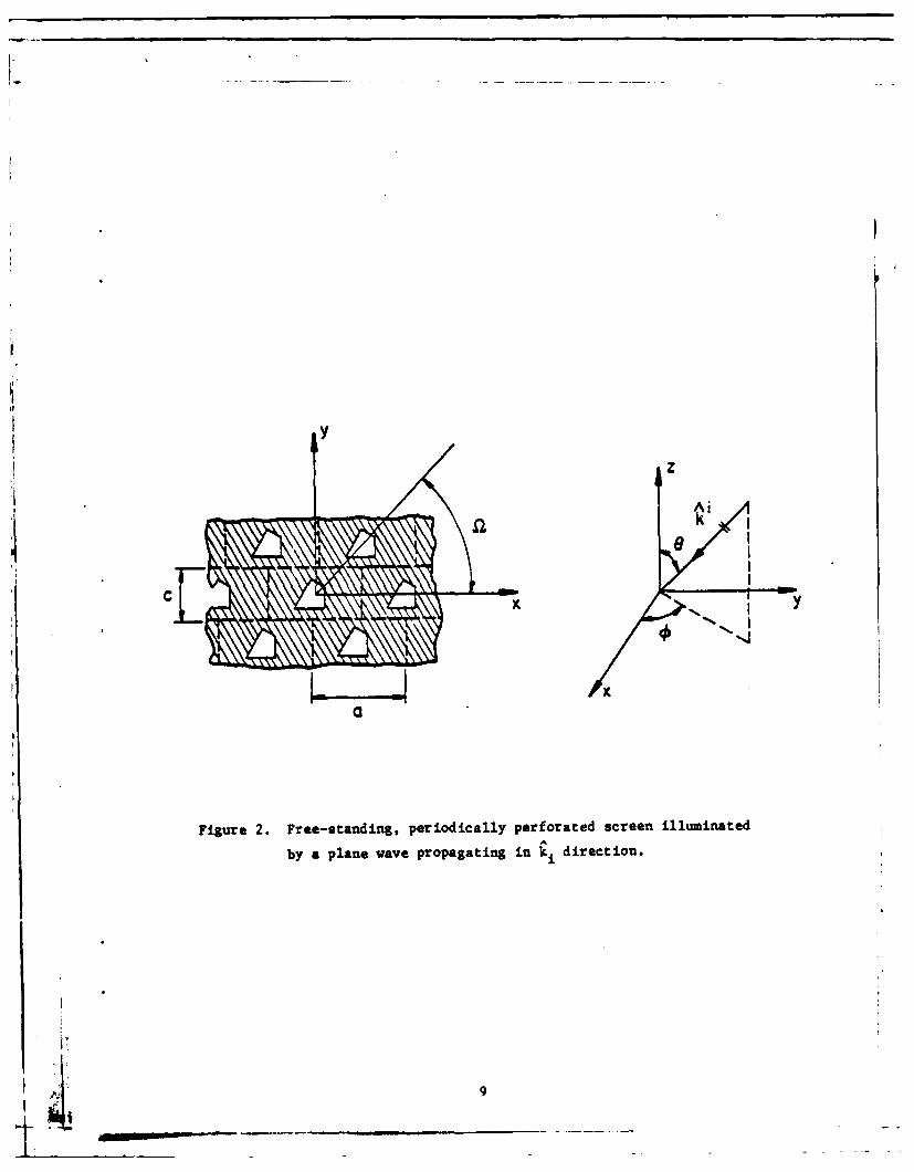
the problem of a uniform plane wave scattered from a free-standing
periodically perforated conducting screen shown in Figure 2. However,
the method of solution is easily and conveniently extendable to the
case of a screen on a dielectric substrate.
Due to the periodicity of the structure, the electric field on
either side of the screen can be expanded in terms of the Floquet
space harmonics. Using the e Jwt time convention (suppressed), we can
write
[x: x 1 L + *Li Z for z > 0
and
x * L:Y:i • for z < 0
y m
8KIL
z
Figure 2. Free-standing, periodically perforated screen illuminated
by a plane wave propagating in k i direction.
_ _ _ _ 9
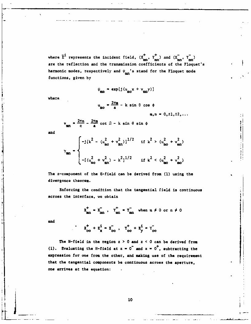
where E represents the incident field, (, Y ) and (X, Y)am mn =9Mn
are the reflection and the transmission coefficients of the Floquet's
harmonic modes, respectively and mn's stand for the Floquet mode
functions, given by
, - exp[j (umo x + v y)]
where2ir
u =--- k sin e cosmo a
m,n = ,1±,.
2irn 27nmvn in- acot k sin 6sin~
and
k2 _u2 + v2 )]1/2 k2> (U2 + v2
-jk -(mo un ifkm
Ym-,2 .2 2 .21/2 2 2 v2
-[(u,~ + v k2 2 if k2 < (uZ + v)
The z-component of the E-field can be derived from (1) using the
divergence theorem.
Enforcing the condttion that the tangential field is continuous
across the interface, we obtain
x -x , y Y- whenm Oorn O:mn mn mn mn
andi+ + i X- Y+ +i -Y
00 x 00 00 y 00
The H-field in the region z > 0 and z < 0 can be derived from
(1). Evaluating the H-field at z - 0 and z - 0+, subtracting the
expression for one from the other, and making use of the requirement
that the tangential components be continuous across the aperture,
one arrives at the equation:
10

A a x -H - + [ iy
'm, -n an2 Ifor z-0"V ar '*C- -H i + O [ jx (2 )L I mJ ,mJ y 2-
ere is the incident H-field,
is the induced current on the surface,
A -u v /S,,, 2 /
2Ymn -Yan'B I " am- ~/Y Ymn"
In (2) we have used the notation that for a function f(;) defined on the
z I 0 plane, where r is the position vector on that plane, the truncs-
tion operator e is defined by
6(f(r)) - f(;) for r on the conducting surface
M 0 for r in the aperture
and(f(r)) I f(r) - (f(r))
The obvious identity 4(J) - J and that i x [((z - 0 ) - H(z 0-)] =
have also been used in deriving (2).
Unlike the integro-differential equation in the conventional method,
which applies only in the aperture (or strip) region, (2) is valid over
the entire surface. The price paid for extending the equation to the
full range Is the introduction of an extra unknown j. However, as we
will soon see, the additional unknown j can be solved for along with the
aperture field using the iterative procedure discussed in the next section.
III. ITERATIVE PROCEDURE
The summation involved in (1) and (2) can be readily identified as
the DFT operation. LUt F be the operator representing the DFT, and let It
~11

represent the tangential electric field in the transformed domain.
Identifying (X n, Y ) in (2) as the Fourier coefficients E t and
writing G for the matrix [: 2:]we can write (2) symbolically as
S- E 41 + 6(j) (3)
where the subscript t indicates the tangential components, and it is
understood that all the quantities are evaluated at z - 0.
If the induced current were available, the solution for Et could
be immediately obtained by invoking (3) and by using
a (F -- H1 + 6(3))) (4)t
In practice, however, J is the unknown to be solved for, together
with E and hence (4) cannot be used directly. Instead of using (4),t = n+l
a recursive relation between the (n+l)th approximate solution E(
and the nth approximation (n) is now derived and the two unknownst
It and J are solved for simultaneously using an iterative procedure.
To derive the recursion formula for we begin with (3),
which relates i(n) and &(n), and write
8( (n) ( =(.) -ia (n) t (a) + s(5)
Substituting (5) into (4), one obtainsI
1(0+1) . Cl(Fl(_iji + O(F(d 1(n)) +Ri)) (6)
Equation (6) is the desired recursive formula. Before inserting1(n) into (5), we adjust its amplitude by multiplying with a scalet
12K

factor K, computed according to the variation expression
' t (7)- <l(n) FC C7)n)),t E t
where <f, g> ae f'g da.aperture
Eqiuation (7) is obtained by applying the one-term Galerkin's
method to (3) using n) as the testing function. It is apparent
that K - 1 when 1n) is the exact solution. K, therefore, also
Prcides an indication of the accuracy of the nth iterated result
in a weighted-average sense.
In the following we proceed to outline an iterative procedure
for solving (6):
1. Begin with an initial estimate E(0). The amplitude of(O) is to be properly adjusted using the scale factortK determined from (7).
2. Compute (0), the discrete Fourier transform of (0)t t
This step car be carried out efficiently using the
FFT algorithm.3 - 2(0)3. Compute GoEt
4. Obtain the DFT of Go E0 using FIT.-i t
5. Subtract -i from the result obtained from step 4.
This gives the zeroth-order approximate solution (0).
Generally, the approximate solution for J obtained in
this step has non-zero values extending beyond the con-
ducting surface. The satisfaction of the boundary con-
dition for the induced current can thus be verified by
checking how well the nth approximation for the current
is confined to the conducting surface.
6. Add 4' to 3(0) obtained in the last step, and take thet
inverse DI? of the ros~lt using FIT.
13
7. Multiply - by the result obtained from step 6.
obtaining (l)
S. Take the inverse transform of (l) to get
The exact solution for E should have zero value ont
the conducting surface. This criterion serves as a
boundary condition check for the approximate solu-
tion 1 (n) obtained in this step.t
9. Repeat the whole procedure, as necessary, using
8(11 ))" to generate the next higher-order solu-
tions J(1) and 1(2) until convergence is achieved.
In the following two sections several examples are presented to
illustrate the application of the technique described above.
IV. SCATTERING FROM GRATINGS AND GRIDS
Let us consider a free-standing, strip grating structure illmi L
nated by a normally incident uniform plane wave as shown in Figure 3.
Let the incident E-field be polarized parallel to the edses of thestrip (an H-wavo).
The formulation for this problem is given by (2). The iterative
procedure discussed in section III is applied to solve for the tan-
gential aperture E-field, it, and the induced current density, J.
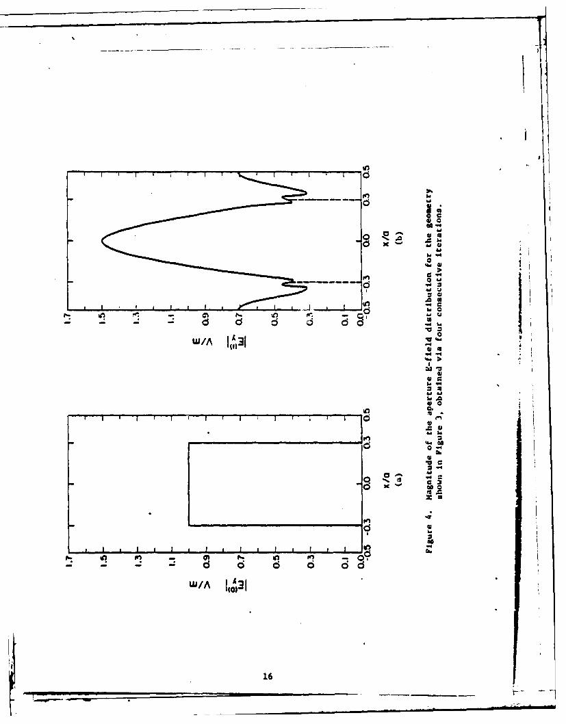
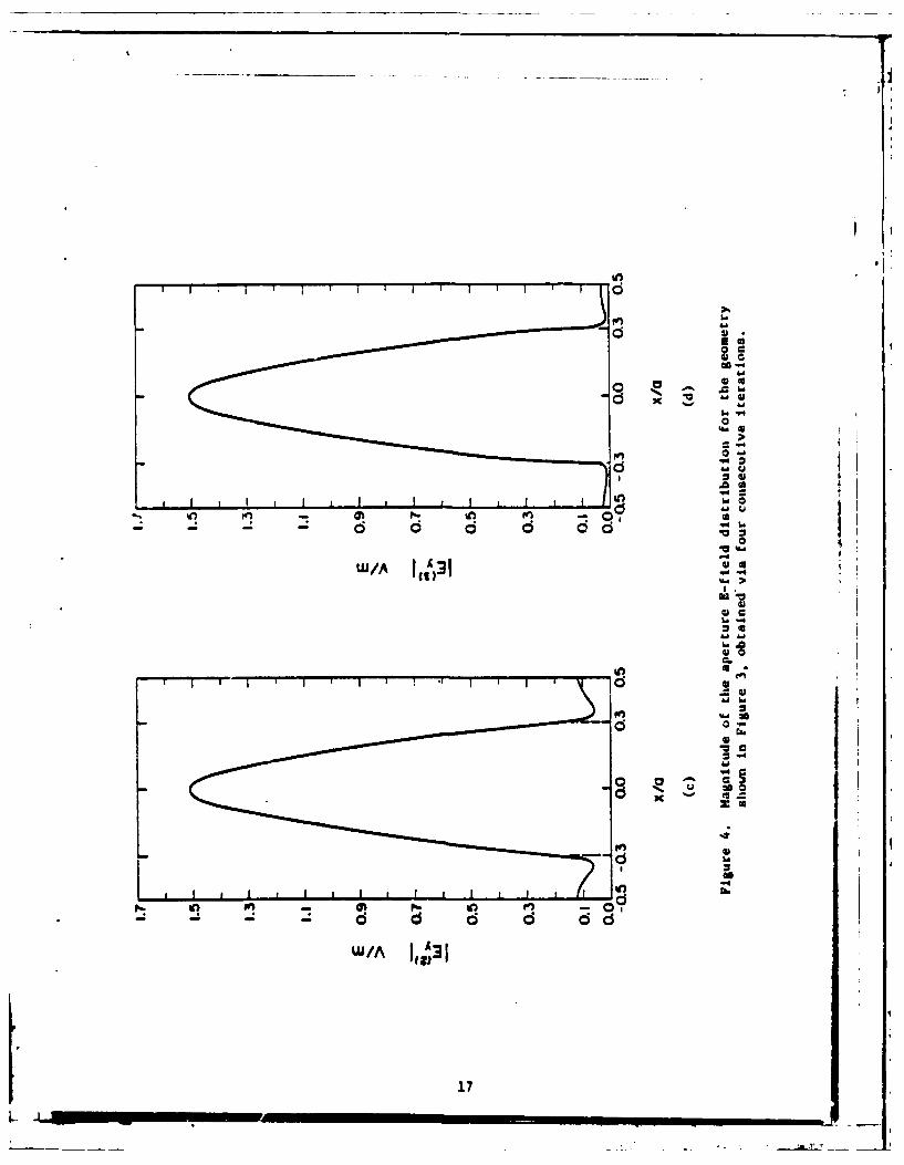
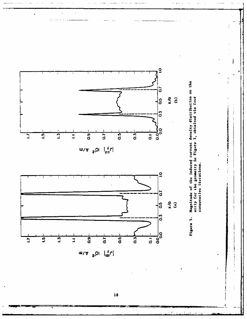
Figure 4a shows the incident R-field truncated in the aperture,
which Is used as the zeroth-order approximation for Eto i.e.,1(0) - 0(1'). The 3(0) derived from 1(o) is shown in Figure 5a. (0)
has significant non-zero values extending into the aperture region.
This could be expected because of the crude initial estimate made for
(0). Figure 5b shows 3(l) obtained after one iteration. Observe the
significant improvement achieved with Just a single iteration even
though the zeroth-order approximation for 1(0) was rather crude. Higher-
order solutions for 1(n and 3(), obtained via further iterations, aretshown, respectively, in Figures 4b to 4d and Figures 5b to 3d. The
14

a" 1.4 X-./
bsO.6a
Ltbb
0 I
figuare 3. Free-standing &rating illuminated by a normally incidentK-wave.
15 ,
RIi
Fn a
Ff.:d
W/ACa16
ol
0 h0 0
0)0
11
a
o g
0^ IL:
16
0 0 V I
0a
WIAI
f I-kf
WS/A 1 3
17 -
rCol
apa
,%Al

rii
41al
a0
In
.4
W/V pi I n xr
-1 - - 6 60
rapid convergence and the accuracy, which is verified by the boundary
condition check of the solutions, are well-demonstrated in these
figures. The induced current density J also shows the expected edge
behavior, i.e., it becomes large at the edges as it should for the
incident H-wave.
Figures 6 and 7 show the solutions for Et and J obtained after
four iterations when the gratings are illuminated by an obliquely
incident plane wave with an incident angle 8 - 30° and with the H-
field polarized parallel to the edges of the strip (in the E-wave
case). Again, the boundary conditions are satisfied extremely well
4y the results, and the aperture E-field also shows the expected edge
behavior for the incident E-wave.
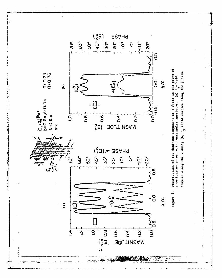
Next we consider the scattering from a free-standing conducting
grid illuminated by a normally incident plane wave. The geometry of
the problem is shown in Figvre 8. The aperture area is approximately2 2
1OA whereas the cell area is about 44X . The initial approximation
for E is still chosen to be the truncated incident field, and thet
dominant component of the tangential aperture E-field is shown when
the incident E-field Is polarized in the y-direction.
For all the computations in this saction, 32 terms in the
Floquet expansion functions are used in representing the unknown
fields along each of the two dimensions. This leads to 211 equiva-
lent unknowns to be solved for. The computation time, however, re-
quired for deriving the solution is quite moderate (5 - 6 secs. of CPU
tim on the CDC Cyber 175 System). Clearly, any matrix method dealing
with such a large number of unknowns will be totally impractical.

c V
r -4
0 fn@ - .4 001
Cu (U V 1
1=
c
c a,
N.
00
1
0
10 0
10 A -4
(03) 3SVHdC)0 0 0 0 0 0 0 0
dd I
ad'
0 0
0 14
00j m~ X a 0
I 0- c x
00
0 V
VD3 1 II i l NO N
- . .22
0t-70

regions of dissimilar dimensions. An open-region type example is a
corrugated surface which can be thought of as a junction of two0
regions, viz., the infinite half-space and a periodic array of short-
circuited waveguides. For the sake of si~aplicity, a closed-region
type problem - a step discontinuity in a parallel-plate waveguide -
is considered in this section. The geometry is shown in Figure 9.
The incident field is a TE mode wave. The formulation of this prob-
lem can be found in the literature. The integral equation is given
byb b
E (x')K-(x,x')dx' Ey(x')K (xx')dx' - 2Hi (8)J y x
0 0
for 0 < x < b, z 0
where E is the unknown aperture E-field,y
Hi is the incident' H-field,x
K(xx') - sin x sin x'jwj in M-0 a a
K4 xx') Ir+ sin --xsin x'jW1 m b b
j(k 2 - (.m)2)1/2 if k 2 > mi2
r- k
ml)r 2 2 if 2 mt 2
and
2 mw 2l1/2 2 miT 2r, J(k_ /2 if k2 > (.)
mit((r 2 _ 2 1/2 ,2 m ( . 2
Note that (8) is defined in the region 0 < x < b. To apply the
iterative technique, ic has to be extended to the full range
S 23

ai"t
y z
Figure 9. Step-discontinuity in a paralel-plate waveguidewith a TE incident wave.
24

0 < x < a. This is achieved by introducing an extra unknown func-
tion J(x), and the extended equation takes the form
a a
E (x ')K- (x x ',dx' - EY(x ')e (x 'x ')dx ' + 8(-2H') + 9(J(x)) (9)0 0
for 0 < x < a
where for any function f(x)
8(f(x)) - f(x) if 0 < x < b
-0 ifb<x<a
and
O(f(x)) - f(x) - o(f(x))
A recursion formula relating the (n+l)th order solution E tothe nth solution Ent y can be derived via a procedure similar to that
developed in section III. The formula is
a a a a
E n~).K_ E n) - e(-2H ) + 98 fE()- En)K- 6(-2H'))
0 0 0 0(10)
Equation (10) is now solved using an iterative procedure similar
to that developed in section III. The integrations in (10) can again
be carried out using the FFT because of the characteristic nature of
the kernels. Figure 10 shows the aperture E-field distribution at the
discontinuity. The initial approximation for E is taken to be theYincident field truncated in the aperture.
The result is obtained in three iterations with 32 expansion
functions used in reprasenting the unknown field. We note that the
boundary condition on Ey, viz., that it vanishes at the edges, is
satisfied by the iterated solution.
25

- x4
C--4
0
C.
LY 131
26.
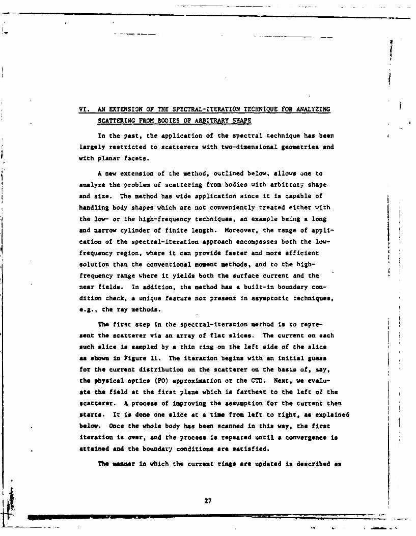
VI. AN EXTENSION OF THE SPECTRAL-ITERATION TECHNIQUE FOR ANALYZING
SCATTERING FROM BODIES OF ARBITRARY SHAPE
In the past, the application of the spectral technique has been
largely restricted to scatterers with two-dimensional geometries and
with planar facets.
j A new extension of the method, outlined below, allows o~ne to
analyze the problem of scattering from bodies with arbitrary shape
and size. The method has wide application since it is capable of
handling body shapes which are not conveniently treated either with
the low- or the high-frequency techniques, an example being a long
and narrow cylinder of finite length. Moreover, the range of appli-
cation of the spectral-iteration approach encompasses both the low-frequency region, where it can provide faster and more efficient
solution than the conventional moment methods, and to the high-
frequency range where it yields both the surface current and the
near fields. In addition, the method has a built-in boundary con-
dition check, a unique feature not present in asymptotic techniques,
e.g., the ray methods.
The first step in the spectral-iteration method is to repre-sent the scatterer via an array of flat slices. The current on each
such slice is sampled by a thin ring on the left side of the slice
as shown in Figure 11. The iteration begins with an initial guess
for the current distribution on the scatterer on the basis of, say,
the physical optics (PO) approximation or the GTD. Next, we evalu-
ate the field at the first plane which is farthest to the left oZ the
scatterer. A process of improving the assumption for the current then
starts. It is done one slice at a time from left to right, as explained
below. Once the whole body has been scanned in this way, the first
iteration is over, and the process is repeated until a convergence is
attained and the boundar~y conditions are satisfied.
The wnnner in which the current rings are updated is described as
27

incIE jP i
IP P+ I
Figure 1U. Cuarrent slices on 3-dimensional scatterer.
28

follows. Consider the pth slice, one which is bounded by the pth
plane on the left and the p+lth plane on the right, and contains
the thin current ring J at its left immediately to the right ofp
the pth plane (Figure 11). At the pth-plane the scattered fieldI4- 4-- * -
consists of two components, viz., E and E . E is the aggregate
of the contribution from all of the sources to the left of the pth
plane. It spectrum is thus propagating to the right and, conse-
quently, the radiation condition dictates the choice of the propa-
gator e- jkzz for any of its plane-wave spectral components. The
second contributor to the scattered field is E , which is the con-p
tribution of all the currents to the right of the pth plane and is
thus propagating to the left. We assume that in the process of
scanning the body from the left to right all the currents to the
left of the pth plane have been updated, implying the E has beenPupdated as well.
We next proceed to update the current in the pth slice, i.e.,
J . To do this, we look at the plane immediately to the right of
J . This plane is shown by the dashed line in Figure 5.1. E canP Pbe transformed to this plane simply by adding the contribution of
J . In the spectral domain we have the expression
+E +G. (11)
where C is the Green's function in the spectral domain, the - super-
script denotes the plane immediately to the left of Jp, and the +
superscript is associated with the plane immediately to the right4.-
of J . Since E is known, we are now able to use the assumed J inP p *+ p
conjunction with (11) to compute 9 and then the total scattered
field
ip- (£+ +E~
p (E E)p
Next, inverse transforming E yields the scattered electric field inPthe spatial domain and the application of the boundary condition
29
allows one to replace the total scattered field E inside the bodyincP
by -E A Fourier transform is then taken and the following equa-
tion is used to obtain the updated E pP
- (updated) - E (12)
Finally, the updated J is derived from (11) and the updated Ep * p
Also, Ep+1 is obtained from E p via the equation
-B- + -jk z AE -~l E pe (13)
This completes the operation on the pth slice and we move to the
(p+l)th slice to repeat the process in order to obtain a new value forJ3+ . We continue in the same manner, proceeding to the successive
slices toward the right until we are finished with all the slices and
have covered the entire body. The end result of this series of steps
is a complete, updated version of the current on the entire scatterer.
Having obtained this, the first iteration is completed, and the whole
process can be repeated.
The iteration process is continued until convergence is achieved,
as indicated by the satisfaction of the boundary condition on and in
the interior of the scatterer.
It should be noted that since the two-dimensional FFT is used,
even for a three-dimensional scatterer, the method is computationally
efficient and its storage requirement is low. Furthermore, since the
boundary-condition check is applied at each stage of the iteration,
the accuracy of the final (convergent) result is guaranteed.
Preliminary studies have indicated that the arbitrary body scheme,
though originally conceived in connection with perfectly conducting
scatterers, may prove useful for handling dielectric scatterers as
vel. It appears that the method may be generalizable to inhomoge-
neous dielectric bodies-as well, although more work remains to be done
to determine the scope and limitations of this approach.
30
§(
-. 0mqm -

VII. REFERENCES
[1] C. C. Chen, "Transmission through a Conducting Screen Perfor-ated Periodically with Apertures," Microwave Theory and Tech-niques, vol. 18, No. 9, pp. 627-632, 1970.
[2] S. W. Lee, "Scattering by Dielectric-Loaded Screen," IEEETransactions on Antennas and Propagation, vol. 19, No. 5,pp. 656-665, 1971.
(3] R. C. McPhedran and D. Maystre, "On the Theory and SolarApplications of Inductive Guides," Appl. Phys., vol. 14,pp. 1-20, 1977.
[4] W. L. Ko and R. Mittra, "A New Approach Based on a Combinationof Integral Equation and Asymptotic Techniques for SolvingElectromagnetic Scattering Problems," IEEE Transactions onAntennas and Propagation, vol. 25, No. 2, 1977.
VIII. BIBLIOGRAPHY ON SPECTRAL DOMAIN METHODS
Books
1. R. Mittra and Y. Rahmat-Sahii, "A Spectral Domain Approach forSolving High Frequency Scattering Problems," in P.L.E. Uslenghi(Editor), Electromagnetic Scattering, Academic Press, N.Y. 1978.
2. R. Mittra, W. L. Ko and Y. Rahmat-Samii, "Transform Approach toElectromagnetic Scattering I," Proceedings of NATO AdvancedInstitute, Norwich, England, 1980.
3. -R. Mittra and Mark Tew, Accuracy Tests and Iterative Proceduresfor High Frequency Asymptotic Solutions - A Spectral DomainApproach, Pergamon Press, 1980.
Journal Articles
1. N. N. Bojarski, "K-Space Formulation of the ElectromagneticScattering Problem," Technical Report AFAL-TR-71-75, March 1971.
2. T. Itoh and R. Mittra, "Spectral Domain Approach for Calculatingthe Dispersion Characteristics of Microstrip Lines," IEEE Trans.Microwave Theory Tech., vol. MTT-21, pp. 496-499, July 1973.
3. Y. Rahmat-Samii, T. Itoh and R. Mittra, "A Spectral DomainTechnique for Solving Microstrip Line Problems," AEU Electronicsand Communications, Band 27, pp. 69-71, 1973.
4. Y.Rahmat-Samii, T. Itoh and R. Mittra, "A Spectral DomainAnalysis for Solving Discontinuity Problems," IEEE Trans.Microwave Theory Tech., vol. MTT-22, pp. 372-378, April 1974.
31
l

5. R. Mittra and T. S. Li, "A Spectral Domain Approach to theNumerical Solution of Electromagnetic Scattering Problems,"AE 1 Electronics and Comunications, Band 29, pp. 217-222, 1975.
6. R. Mittra, Y. Rahmat-Samii and W. L. Ko, "Spectral Theory of
Diffraction," Appl. Phys., vol. 10, pp. 1-13, January 1976.
7. Y. Rahmat-Samii and R. Mittra, "A Spectral Domain Interpretationof High Frequency Diffraction Phenomena," IEEE Transactions onAntennas and Propagation, vol. 25, pp. 676-687, September 1977.
8. Y. Rahmat-Samii and R. Mittra, "On the Investigation of Dif-fracted Fields at the Shadow Boundaries of Staggered ParallelPlates -- A Spectral Domain Approach," Radio Science, vol. 12,pp. 659-670, September/October 1977.
9. R. ,ittra and W. L. Ko, "An Approach to High-Frequency Scatter-ing from Smooth Convex Surfaces," IEEE Transactions on Antennasand Propagation, vol. 25, pp. 781-788, November 1977.
10. W. L. Ko and R. Mittra, "A New Look at the Scattering of a PlaneWave by a Rectangular Cylinder," AEU Electronics and Communi-cations, pp. 494-500, December 1977.
11. Y. Rahmat-Samii and R. Mittra, "Spectral Analysis of HighFrequency Diffraction of an Arbitrary Incident Field by aHalf Plane - Comparison with Four Asymptotic Techniques,"Radio Science, vol. 13, pp. 31-48, January/February 1978.
12. R. Mittra and M. Tew, "Accuracy Test for High-FrequencyAsymptotic Solutions," IEEE Transactions on Antennas andPropagation, vol. AP-27, No. 1, pp. 62-67, January 1979.
13. R. Mittra, W. L..Ko and Y. Rahmat-Samii, "Solution ofElectromagnetic Scattering and Radiation Problems Using aSpectral Domain Approach -- A Review," Wave Motion J.,vol. 1, No. 2, pp. 95-106, April 1979.
14. R. Mittra and S. Safavi-Naini, "Source Radiation in the Pres-ence of Smooth Convex Bodies," Radio Science, vol. 14, No. 2,pp. 217-237, March-April 1979.
15. R. MHitra, W. L. Ko and Y. Rahmat-Samii, "Transiorm Approach toElectromagnetic Scattering," Proc. IEEE, vol. 67, No. 11,pp. 1486-1503, November 1979.
16. M. Tev and R. Mittra, "An Integral E-Field Accuracy Test forHigh Frequency Asymptotic Solutions," IEEE Transactions onAntennas and Propasation, vol. AP-28, No. 4, pp. 513-518,July 1980.
17. 1. Mittra and R. Kastner, "A Spectral Domain Approach for Com-puting the Radiation Characteristics of a Leaky-Wave Antennafor Millimeter Waves," AP-S Trans., (to appear) 1980.
32

18. S. Savavi-Naini and R. Mittra, "High Frequency Radiation fromElectromagnerlc Source Located on a Finite Cylinder -- ASpectral Dcmain Approach," AP-S Trans., (to appear) 1980.
33
I

APPENDIX B
A SPECTRAL DOMAIN APPROACH FOR COMPUTING THE RADIATIONCHARACTERISTICS CF A LEAKY-WAVE ANTENNA FOR MILLIMETER WAVES
R. Mittra and R. Kastner
ELECTRICAL ENGINEERING DEPARTMENT
UNIVERSITY OF ILLINOISUxBANA, ILLINOIS 61801
ABSTRACT
This paper deals with a new method for evaluating the complex
propagation constant 8 in a leaky-wave structure comprising of thin,
metallic rectangular strips etched on a dielectric rod of rectangular
cross section. The radiation pattern of the leaky wave antenna can be
determined once 0 is known, since Re(8) governs the direction of the main
beam and Im(0) accounts for the beamwidth and aperture efficiency. Tn
addition, the knowledge of the dependence of 8 on frequency allows one to
design the antenna for frequency-scanning applications. The method
employed in this paper is based on the spectral domain appro,:h which
formulates the elgenvalue problem in the Fourier transform dumain.
Computed results are shown to be in very good agreement with experimental
measurements.

1. Introduction
In this paper tie describe a novel mrthod for eval ating the complex
propagation constant B in a leaky-wave structure comprised of an array of
thin, metallic, rectangular strips etched on a dielectric rod of rectangula-
cross section. The geometry of the problem is shown in Figure 1. This
configuration finds useful applications as a frequency scannable antenna,
particularly at millimeter waves where the antenna can be conveniently
integrated with dielectric-based planar integrated circuits [1,2,3].
The complex propagation constant $ along a leaky-wave antenna
determines the radiation pattern of the antenna. Specifically, Re(U) gover:ns
the direction of the main beam, and Im (8) accounts for the beam width and
aperture efficiency. In addition, when the dependence of 8 on frequency
is known, it is possible to design the antenna for frequency-scanning
applications.
In the past, the determination of 8 has often been accomplished via
experimental means, mostly by near-field probing techniques. Analytical
evaluation of B has been carried out for structures for which the leaky
wave is generated from guiding structure which supports a fast wave, e.g.,
a slotted waveguide [41. For such a structure, B differs only slightly
from the guided-wave propagation constant in the absence of the slots as

sets of networks are required for every hybrid mode. In addition, the dis-
.xntinuities mubt be incorporated into the equivalent network by lump-element
reresentation, which by themselves may require the solution of some involved
boundary-value problems.
In this paper we employ a method based on the spectral approach which
formulates the eigenvalue problem in the Fourier transform domain. A des-
cciption of this method appears below.
2. Formulation of the Problem
The formulation of the problem is based on the spectral don.ain
approach which has the following advantageous feature. The Green's function
for the dielectric substrate region is conveniently expressible in the trans-
form or spectral domain in a closed form, whereas it takes a complicated form
in the conventional space domain approach.
Referring to Figure 1, let us consider a y-polarized wave traveling
along the z-direction. Because of the periodic nature oc he geometry, we
can express the fields propagating along the struc.ure in terms of Floquet
space harmonics with wave numbers 8 (=S+ 2nr/6), where 8 is the complexn
wave nuT.ber we are seeking. It is evident that only a finite number of 8n
are in the visible region, i.e., satisfy the criterion IRe snI < k, where k
is the free-space wave number, and on].y these B contribute to the leaky-waven
radintion. Typically, these leaky-wave antennas are designed such that
n - ±1. As alluded to earlier, the real part of B+i determines the direction
of the main beam and its scanning properties, whereas the imaginary part
determines the beamwidth and efficiency of the antenna.
36
-- -- _ L , .,. z=, ,,( = ...... ..- -- -

As a first step toward attacking this problem, we replace the
dielectric rod with a slab using the well-know effective dielectric
constant method [6], [7]. The effective dielectric constant is given
by r _ky2
eff 1k
where k is the free-space wave number and k is the fundamental mode irthY
spatial frequency corresponding to the cosine variation in the y-direction
inside the dielectric. Next, the Green's function for the geometry is
constructed in the spectral domain, because the expression for the Green's
function in the transform domain is considerably simpler than the corres-
ponding one in the space domain. The expression for G, the two-dimensional
Fourier transform of the spatial-domain Green's function for the E-field
of y-directed point source located at a distance d above the dielectric
surface (Figure 2), is formulated in a fashion similar to Collin's (8].
It is given by
G(::,u,'
(k~l + k)e -j k x 2T
-k )e -jk Ix-diu2) x. 1 ()xl x2_ xl"-.. 1- u _e e
0 2jk x2 T . _x2-Tj
+xl + " 2 - (k.i - kx2 ) (2)
where
k xl F =iV
k x 2 E e f f u - v "
37
-T _ I HI I-
and u and v are the transform variables corresponding to the y and z
directions, respectively. These are normalized with respect to k; hence,
all the dimensions are expressed in te-s of electric length (radians).
In our case, d-O. The tedious Fourier inversion of (2) is avoided
by keeping the rest of the development in the transform domain. The
re;resentation for the electric field in terms of the current distri-
bution on a strip takes then a simple form of algebraic product (as
opposed to convolution in the space domain). Ile have
E ,G(o,u,v) - JCo,u,v) (3)
where J is the transform of the assumed current distribution on the
strip. Since w < < L, it is reasonable to assume a cosine variation
in the y direction and uniform distribution in the z direction. J
is then proportional to
uL vJcos - sin
J(u,v) 2 (4)
To obtain the eigenvalue equation, we superimpose the electric
iields generated by the periodic array of strips and apply the boundary
cc--.dtion that the total electric field on a representative strip isth-jnzero. The n thstrip is characterized by an amplitude e- J Wn & and a
displacement of nA in the z-direction. Therefore, the transform of
its current distribution is
Sj e eJ(v-d)nL (5)n
38
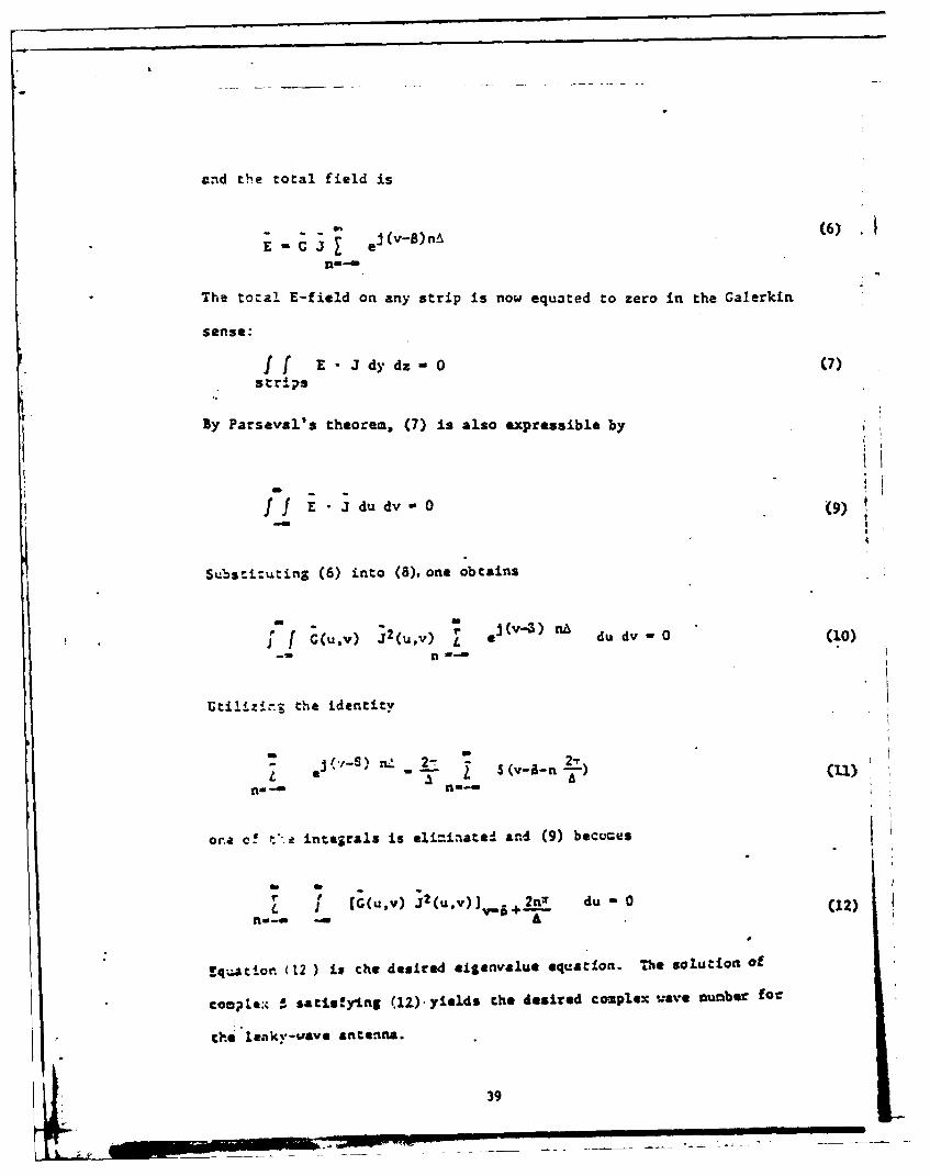
and the total field is
3(v-)nA (6)
The total E-field on any strip is now equ3ted to zero in the Galerkin
sense:
f E - J dy dz- 0 (7)
strips
By Parseval's theorem, (7) is also expressible by
f E J du dv- 09)
Substi-u:ing (6) into (8), one obtains
a m
-- (V---4aj'f (u'v) J 2 (uv) r a~4 du dv -0 (10)
Utiiazing; the identity
S ej ( v -n) .1 2 - 2-r" "" 2 ,(v-8-n-)flU -8 flin-
ora c! --. integrals is eli=inated and (9) becores
r. F
L I [C(u.v) 2(u,.v)jv. +.L. r du o (12)no a -AW
q~aton. (12 ) is the desired eiegnvalue equation. The solutioa of
CoMpLe. a satisfaying (12). yields the desired complex wave number for
0-e leaky-,ave ante.n.
39
3. Results.
Equation (12) requires an integration along the real axis in the
u-plane and a summation over all Floquet modes. Since all the consti-
tuents of (12) are symmetric with respect to real u, the integration
need be carried out only along half of the u-axis. Moreover, there
appears to be little or no contribution to the expression beyond u - 2
Pad In Z 2.
The solution for 6 is obtained via a search procedure which
seeks the zeroes of Eq. (12) within some numerical tolerance. The antenna
under consideration had 29 strips with the following dimensions at the center
frequency of fo - 80 GHz (see Figure 1): L 0.8, T - 0.3r67A, W - 0.3387).,
a - 0.6667A, and with e - 2.46. The computed B for f - 0.95f0 , 1.05fo and
1.1f was -. 31 -J.03, -.222 -j.05, -.13 -J.03 and -.05 -J.03 respectively.0
These solutions account for main beam directions of 1080, 1030, 97.5 and 930
Ith respect to the z-axis, comp:ared to the experimental values of 1090,
103 98 nd 920. These values of £ correspond to a backward wave (n -1).
The real part of the fundamental (n o) B differs very little from that of
an unloaded dielectric rod and can be predicted by approximate methods [1-31.
However, the imaginary part of 8 has not been analytically computed before
for this structure. The experimental results, obtained by near-field probing
techniques, yield Im(3) a -.03 which is in very good agreement with our
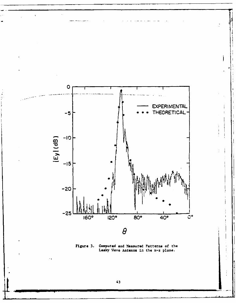
t~ecry. As ge:2n from Figure 3, the measured and computed beam widths, of
about 50, also agree well with each other. The behavior of the experimental
pattern in the side-lobe region is attributable to the radiation from the
pattern feed region which was not modeled on the theoretical calculations.
40

METALSTRIPS
C'oELEC I P,
SUESTRATFE
Figure 1. .eaky wJave Antenna configuracion.
41
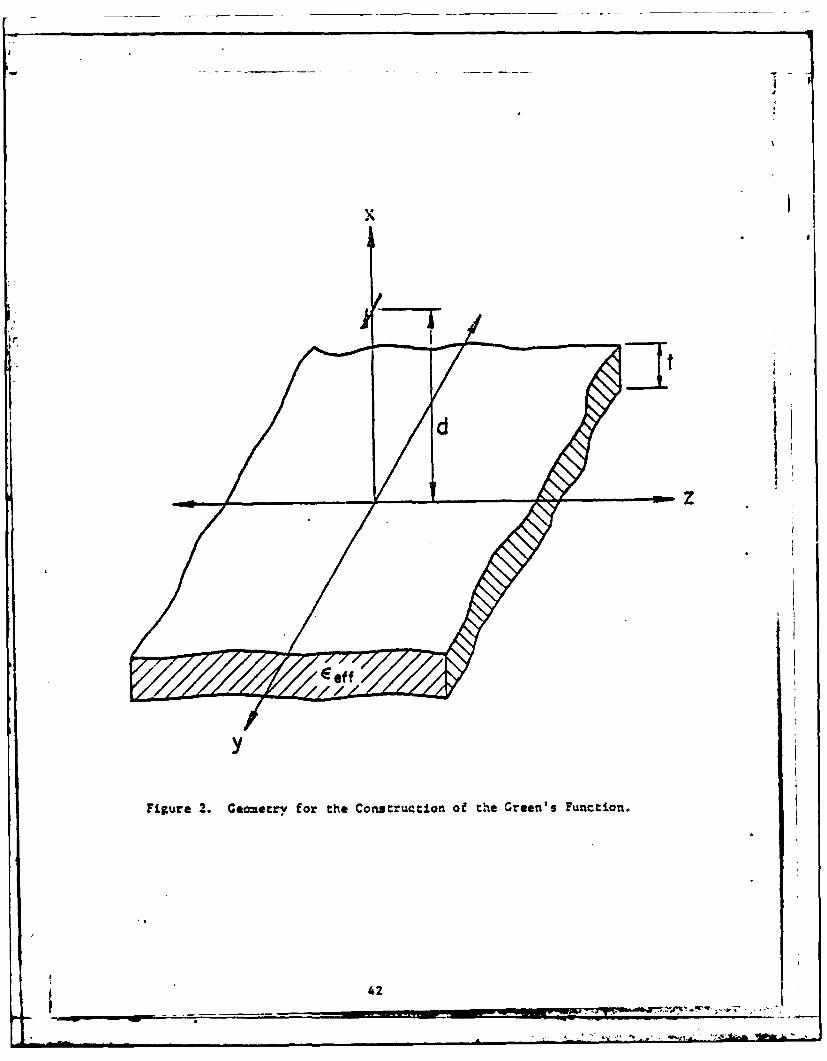
Figure 2. Geometry for thle Construction of the Green's Function.
42
I
0 -
EXPERIMENTAL-5 - @ THEORETICAL-
m -IO 0
-15
-20. i'
1601 120 ° 800 40c 00
Figure 3. Couputed and leasured Patterns of theLeaky W.ave Antenna Ln the x-z plane.
43
References
[11 K. L. Klohn, R. E. Horn, H. Jacobs and E. Freibergs, "Silicon
Waveguide Frequency Scanning Linear Array Antenna," IEEE Trans.
Microwave Theory Tech., vol. MIT-26, pp. 764-773, October 1978.
[2] S. Kobayashi, R. Lampe, N. Deo and R. Mittra, "A Study of
Millimeter-Wave Dielectric Antennas," 1979 AP-S International
Symposium Digest, pp. 408-411, June 1979.
[3] K. Solbach, "E-Band Leaky-Wave Antenna Using Dielectric Image
Line with Etched Radiating Elements," in 1979 MTT-S International
Microwave Symoosium Digest, pp. 214-216, April-May 1979.
[4] T. Tamir, "leaky-Wave Antennas," chapter 20 in: R. E. Collin
and F. J. Zucker, Antenna Theory, Part II, McGraw-Hill, 1969,
pp. 259-297.
(5] L. B. Felsen and N. Marcuvitz, Radiation and Scattering of Waves,
chapter 2, Prentice-Hall, 1973.
[6] R. 14. Knox and P. P. Toulios, "Integrated Circuits for the
Millimeter Through Optical Frequency Range," in Proc. Symp.
Suboillimeter Waves (New York), March 31-April 2, 1970.
[7] W. V. McLevige, T. Itoh, R. Mittra, "New Waveguide Structures
for Millimeter-Wave and Optical Integrated Circuits," IEEE Trans.
Mi:rowave Theory Tech., vol. MTT-23, pp. 788-794, October 1975.
[81 R. E. Collin, Field Theory of Guided Waves, chapter 11,
McGraw-Hill, 1960.
44

APPENDIX C
RADIATION FROM AN OPEN-ENDED WAVEGUIDE WITH BEAM EQUALIZER -
A SPECTRAL DOMAIN ANALYSIS
Wai Lee Ko, Vahraz Jamnejad, Raj Mittra, and Shung-Wu Lee*
ABSTRACT
A septum and an impedance matching post are used as a beam equalizer
in an open-ended waveguide-feed for reflectors used in satellite communica-
tions systems. The performaxce of this design over a frequency band is
evaluated usiag a spectral domain approach. The computed radiation
patterns in the E- and H-planes, as well as the results for the impedance
match, are presented in the paper.
W. L. Ko, R. Mittra, and S. W. Lee are with the Electromagnetics Laboratory,Department of Electrical Engineering, University of Illinois, Urbana, IL 61801.V. Jamnejad was with the Electromagnetics Laboratory. He is now with JPL,4800 Oak Grove Drive, Pasadena, CA 91103.
The work was supported by the Office of Naval Research, Contract
N00014-75-C-0293. 45

I. Introduction
Rectangular waveguide array feeds for reflector antennas play an
important role in the design of satellite communication systems. To make
the radiation pattern more symetric in the E- and H-planes of the feed,
a beam equalizer is needed. The design used in this case is a septum placed
across the mouth of the waveguide such that the aperture distribution is
reshaped to satisfy the new boundary conditions imposed by the septum.
Consequently, the H-plane radiation pattern is narro-ed to approach the
E-plane pattern, thereby achieving the beam equalizing effect. However,
the introduction of such a septum creates an impedance mismatch problem for
the feed. To alleviate this problem, a matching post is placed behind the
septum so that the reflection back into the waveguide is minimized.
The performance of this design over the desired frequency band is
evaluated using a spectral domain approach, or more specifically, Galerkin's
method applied in the spectral domain f1]. The scattered fields on both
sides of the beam equalizer are represented in terms of their Fourier
transforms or spectra which can be related to the induced surface currents
on the septum and the post. These unknown induced currents are expanded in
terms of known basis functions and unknown coefficients. A matrix equation
for the unknown coefficients is derived by applying the boundary conditions,
and the moment method is then employed in the spectral domain to solve for
these unknown coefficients, which in turn give the answer to the unknown
scattered fields. The scattered fields for all modes obtained in this
manner are than used to compute the reflection and transmission coefficient3
for each mode, propagating or attenuated. A tacit assumption made is that
the scattered field on the open-ended side of the waveguide is the same as
46

that in an infinitely long waveguide containing the beam equalizer. In
other words, the truncation effects of the waveguide are igrored in
this analysis. The transmission coefficients are used to weight the
radiation field due to each mode of waveguide and the superimposed
radiation pattern is computed. The reflection coefficients are used
to assess the impedance matching performance. Numerical results indicate
that the E- and H-plane principally polarized patterns are equalized
extremely well over the entire frequency band of operation and that the
impedance matching is also quite satisfactory.
I. Analysis
The geometry of the waveguide with septum and post is shown in
Figure 1. Since the cross-section of the post is very small, the post
is modeled as a narrow strip to simplify the analysis. The incident
field is propagating in the z-direction towards the post as shown
schematically in Figure 1. There are surface currents induced on the
septum and the post due to the incident field. The scattered fields
radiated by these induced surface currents then propagate in both the
z-direction and the -z-direction, giving rise to the transmitted and
the reflected waves, respectively. In the following analysis, the
truncation effects of the waveguide at z-O are ignored, as though the
post and septum were located in an infinite guide.
The incident field in the waveguide can be expressed in terms of
TE and TM modes in the usual manner:
TE wdes:
i b ffTzE jh _ = coo (-x) sin y) exp ja
47
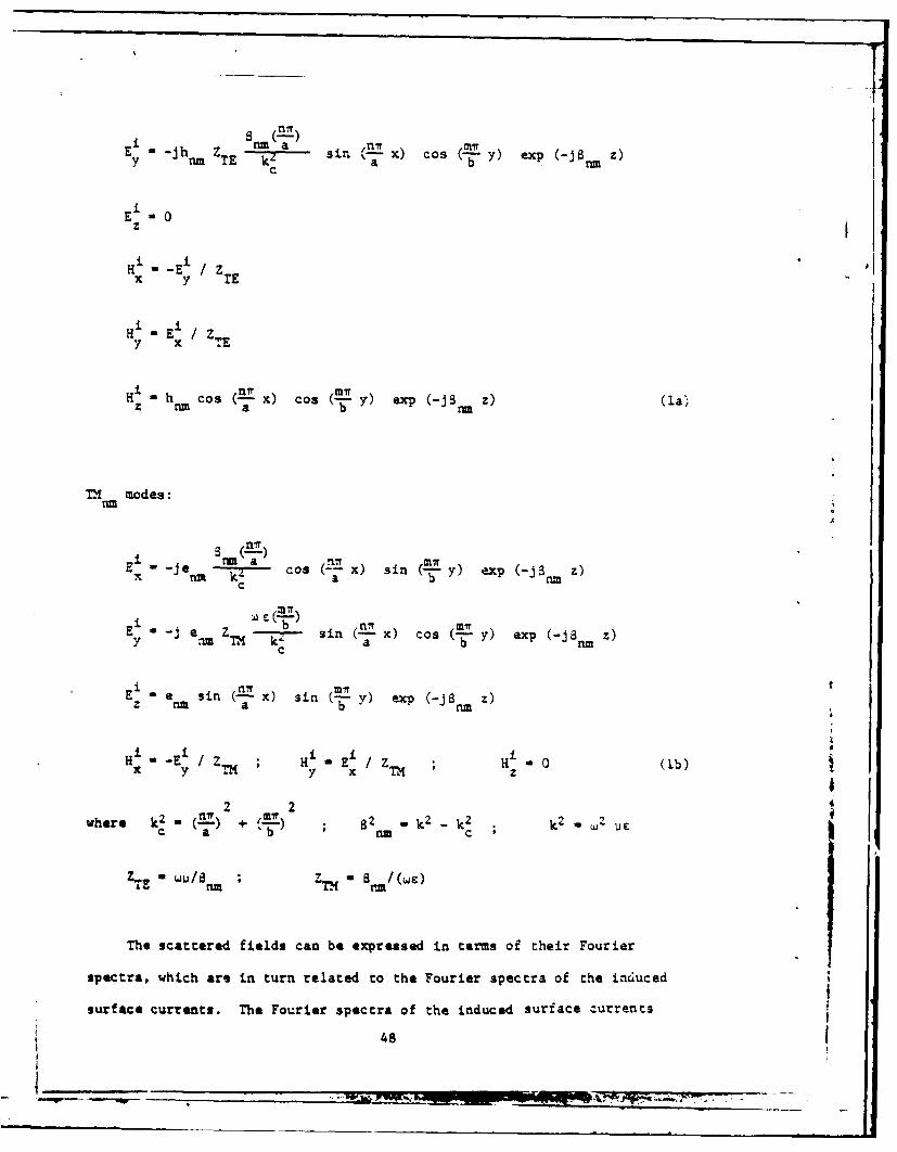
y -jh Z B - a sin V'= x) cos y) .xp (-JB z)y nmZT 2 sir aT O b nc
iE 0oz
Hi -E /Zx y TE
Hi -E / Z7 x
H h cos (- x) cos ( y) exp (-JB z)z rm a bi
TH modes:
Ei) r i ml?- -Je -n kl-- cos (T x) sin (-- y) exp (-jn z)
c
E7 -j en Z b-- sin nT X) Cos -- Mry) exp (-jS Z)
x rm M- a : 7
c
E a e sin (2x) sin (-y) exp (-JB Z)z a a b )-nm
i . E / z H ~ E± / ZH 0 (1b)x y TM y x TM z 0
2 2where k' -(n) + B2 k2 -k 2 k2 .m 2 u
IZTE U B/m~c
The scattered fields can be expressed in terms of their Fourier
spectra, which are in turn related to the Fourier spectra of the induced
surface currents. The Fourier spectra of the induced surface currents
48

are then solved for by the moment method applied in the transfolmed,
i.e., the spectral domain. Specifically, Galerkin's method is used
in the present analysis - the same basis functions are used as testing
functions in the moment method. Upon solving the spectra of the
induced surface currents, the scattered fields can be obtained in
a straightforwnri manner. The analytic details follow.
Ccrresponrdng to each incident mode, the scattered fields E5 andx
Es can be represented in the following form:z
(2)
E (b/2 ynb sinty CCo x) / (a) exp(-Jaz)da,
Es (0< y< b/2) sin Y y
where
n( 2)Y [ (kb- <-) -< bn
and f n), g ( s) are the unknoi- Fourier spectra to be determined. The
n n
i ~~~ as (~<b2 csY
expression for E is then obtained from the \Uxwell's equation 7 -0,
giving
FE (b/2 < y < b)1 OS' -(-
Iasin@Zx) h (a) exp (-Jciz)dcta n (4)
Eys (0O<y <b/ -Cos Y >
494 -
Ma
with
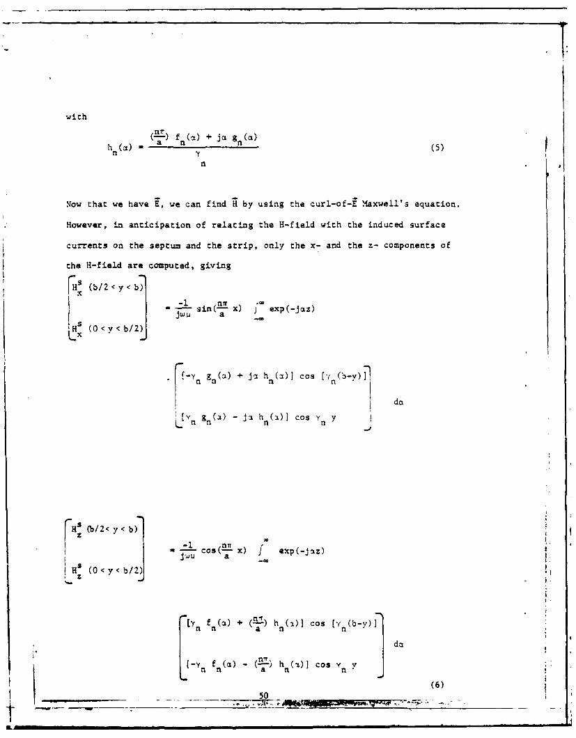
"2-") f a(at) + j a&(CL)h(a) - (5)n y
n
Now that we have E, we can find H by using the curl-of-E Maxwell's equation.
However, in anticipation of relating the H-field with the induced surface
currents on the septum and the strip, only the x- and the z- components of
the H-field are computed, giving
-i-1 sin(Elx) x) exp(-Jaz)JJ LA a -
(0 < y < b/2)j
(-Y gn(a) + Jc hn (a)] cos [rn(b-y)T
da
![vn gn (a) - ja h (a)] cos Y n ynn n .
a: ('b/2< y< b)]
-i cos(-a x) I exp(-jcLz)
H: (0<y<b/2)1 [ f (CL) + ()h (:0] Cos (y(b-y)IFn n a n n
-Y f (a) " -) h (1)] Cos y "
(6)
50 '
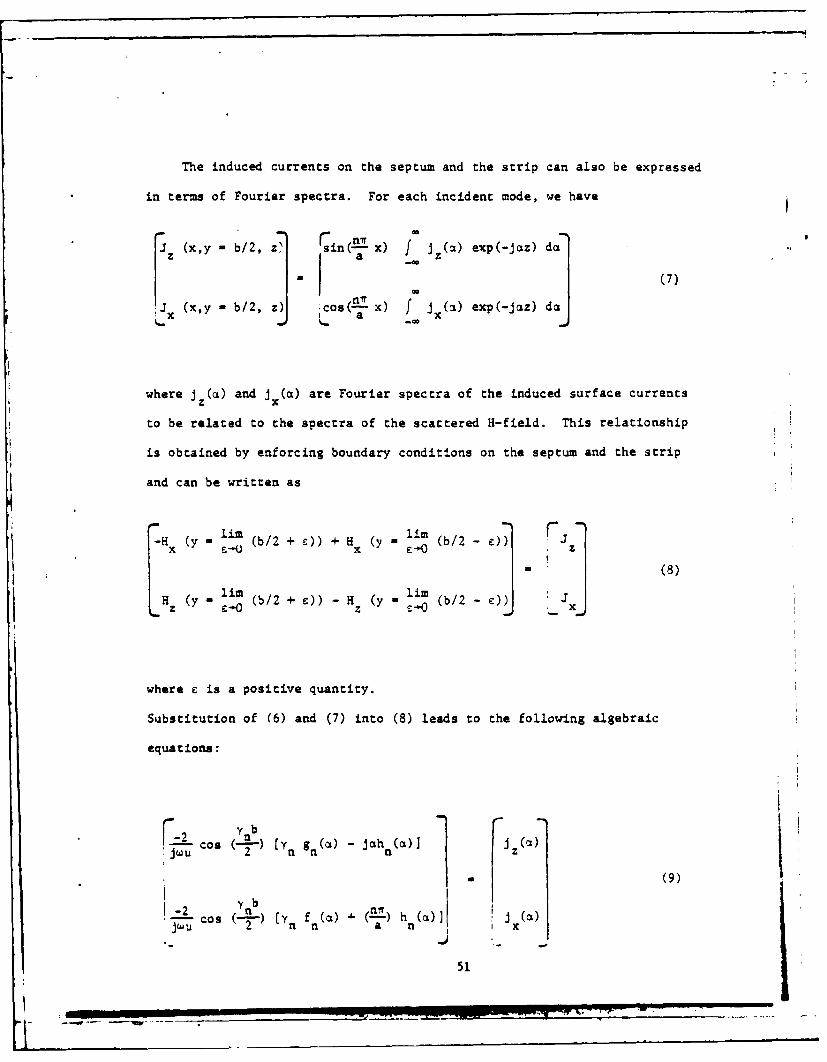
The induced currents on the septum and the strip can also be expressed
in terms of Fourier spectra. For each incident mode, we have
J (x,y - b/2, z sin(-nx) f j (a) exp(-Jaz) da
. (7)
. (x,y - b/2, Cos( ni-x) f (a) exp(-Jciz) d(
where j z(a) and j x(a) are Fourier spectra of the induced surface currents
to be related to the spectra of the scattered H-field. This relationship
is obtained by enforcing boundary conditions on the septum and the strip
and can be written as
-H x(y - EUr (b/2 + 0)) + H x y - l--m (b/2 - e)) zj- (8)
H (y- li (b/2 )) - H (y - 1 (b/2 ]where e is a positive quantity.
Substitution of (6) and (7) into (8) leads to the following algebraic
equations:
F=2 y nb r
*j-- cos (-) Cyn gn(a) - jahn(a)] 1 (
(9)nb
_:.2 Cos -D) Cy f (a) n, h (a)]j5 n n 1
51

Substituting h n from (5) into (9) and manipulating the resulting equationsleads to the following matrix equation for f n(a) and g n(a) in terms of thetransform domain currents j x() and J z(a).
iJ X C1 2 t f (a)(a)a 2 n i u
a2 - b
(10)k2 -2 2cos(--)
An inversion of (10) gives
i " ___- ___ u a-"2 Jz
ef r of) the Iii i::;j): k 2-n)
n ' 2
zbg :)l2k 2 -Y Cos ( - -nz2k2 2 (
If the Fourier transforms of the currents j z(a ) and x (a) are known, wecan obtain fn(a) and gnja) from (1i) . Subsequently, (2), (4) and )cabe used o derive the scattered fields by substituting for f(A) and gn()
in hose exprssons. The remanng task is to solve for the transform
currents jz(a ) and ix(a), using the Galerkin's method applied in thetransform domain.
First we exress the corresponding space domain currents in terms ofa linear combination of a sec of suitable basis functions with unknown
coefficients.
52

r(X, z) cos (--A) A + tAOPO (z)
Li
L za c xn1 J
os (---- X) Jx( Z
sin x) (12)
where U and U are truncation functions on the septum and the strip,c t
respectively,
I-c<Z<O,UCU otherwise-2
Ut -(c + d +- t)'cz<-(c+d)
otherwise
and p0 (z), pi(z), and q,(z) are basis functions to be defined later.
Since the post is assumed to be of very small radius, we model it as
a strip of width t, which is also small. Hence, only the x-directed current
on the strip is expected to be significant. In (12), the unknowns to be
e.valuated are the coefficients A's and B's. From (7) and (12) it can be
seen that
AP (CO
LQLnz (ZBJL - 1 j (13)
where* 0
P pi(Z) exp (Jaz) dz, i 1, 2, ... , I
1 (-(c+d)0 "' )-(c+d+c) PO(z) exz (jnz) dz
53
0
Q() - q,(z) exp (jaz) dz, Z -1, 2, ... , L (14)
Replacing (13) in (11), one obtains the expressions for the transform
domain functions f (a) and G (a):
2( 2- 1 nit ZLfn(a (k2 _n r A iP ±(a)I a EB QZO
-jW U aZ i-a;01* 2k2'y con (
n( ) r A (cL) + (kZ-aZ B)n a Zi~ Z I
Substituting these expressions in (2), (4) and (6) we obtain the final
results for the scattered fields in terms of the unknown coefficients
A's and B's. In order to find these unknown coefficients, we enforce the
boundary condition for the electric field on the se.tum and the strip,
which requires the total tangential component of the electric field to be
zero, i.e.,
Lx xL ba , at Y b
LI L -EJ aty-(16)
Using (1), (2), and (15) in (16) we derive the following equations for A's
and B's.
F m an-. .A) f n tan. P (bJ ) exp(-jpz) da
tan (b) Q1 ( ) exp(-Jaz) da
54
It-,

-2 T nr-WU - 2 nm sin( 2 exp (+8 ~nmZ), for TH modes.
k Mik
2 AT-- h sin(- ) exp ( JS z), for TE modes.b k2 im 26 m
2 I si h ) x (+ j~ z), for TE modes.
b 2. rim 1. rim
C
A, f ) tan - (=C) exp (-ai') do
L f2 ybZtn (--B1 -) () p (a) d
Y 2 5
1-1-
( 21k2 sin (M- exp (+JS z), for TH modes
Nwmultiply both sides of (17) by the basis functions p (z) and q Wz and
integrate over z to obtain the following equations.
22it2 1 y nb(k Z ~A, f -tan(-P,()ia)d
a i0O -0 a
* 55
AmI = ~ = - - -
2A p*, 2 ),a nm k ( sin nm'-O .,I for TM modes
W U k2 enm 2 P (c £ nm
rJ
- h sin !- ,-0,1,..,l for TE modesbi 2 2~ nm 2'O~, ,l to? mde
ci I.,
I .
n' .Z A, -c2 tan (--) ?,(a) Q, () d
L 2= k-2 Y b
+ B (kQCn - Q(a)I n
0 , -1,2,... ,L for TE modes (18)
The upper quantities within the square bracket in (18) are associated
with positive z incident modes, and the lower quantities are associated
rith negastiv - incident modes. Both cases are included because we are
intertsted in the transmission coefficiernts as well as the reflection
coefficients. The integrals Are evaluated by numerical integration, and
the resulting system of line&: equations is solved as usual for the
unknows A's and B's by matrb .nversion.
56
The choice of basis functions, i.e., the 9s and q's, is based on
previous experience and the consideration of the behavior of theI
currents ac the edges of the septum and the strip. Only two terms for
the expansion of the currents on the septum are retained, which are
believed to be adequate for this analysis. The basis functions and
their Fourier transforms are shown in Table 1.
Let us now consider the case of interest, namely, one in which the
incident fields are TE0 modes. We have n-0, and the following relations:
2 2 2YO a - Mt (19)
2
2 2 mwrS ak -(-) (20)Om b
iNhen n-0, (18) can be simplified to the following
2 tanZ i Pi(a) i*,(a) d,1 -0 -- 0 b
2
" ± sin(mw ho m , i-0, 1, 2air 2I P.it (Sum
2 Om
Z Bt f Y tan (--) Qt(a) Q*,(m) da 0 0, Z'=1,2 (21)L,, -*,
The equations for A's and B's are uncoupled. Therefore, A's and B's can
be solved for separately. The system of equations for B's is homogeneous,
57

which leads to the conclusion that all B's are zero. Consequently, there
are no components of the current in the z direction either in the septum
or the strip. In the following development, only the system of equations
for A's is investigated. Observe that the solution of A's involves an
inversion of a 3 x 3 matrix, which is an easy task for the computer. How-
ever, the evaluation of the matrix elements involves nine complex integrals
to be numerically integrated. Since there are singularities in these integrals,
we must examine the integrands carefully to make sure that the numerical
integration is applied correctly to give accurate results in spite of the
singularities. Therefore, it is useful to write the expressions appearing
in the integrands of (21) in an explicit manner as follows:
PoP - e (-2 tn-,2']
2
p P* -y exp () e x
1 0 16V4
01 16(7 exp -(-) I exp [ 2ja + d +
1 16 7 0l 2Se e 4 2ct [.(. .2 c t
P((7 1*- j exp (( + d +
2 !*jc at
22
c2
i~p p*u 1 2 (Cal
1 1 16 0 2
2
2 2 16 1Z (22
58
;-74M.7.7

Note that P P2P , etc. are not of interest here because the corresponding
integrands are odd and therefore the integrals involving them are identically
zero. Now observe that the integrand in (21) contains a simple pole located I
at a - 0 on the path of integration for 0 < a < , provided that the01
wave number satisfies the following condition:
Ir < k < 3 "(23)
k< b
This is the case when the incident field is the dominant, propagating mode
in the waveguide. Introduction of some loss in the medium clarifies the
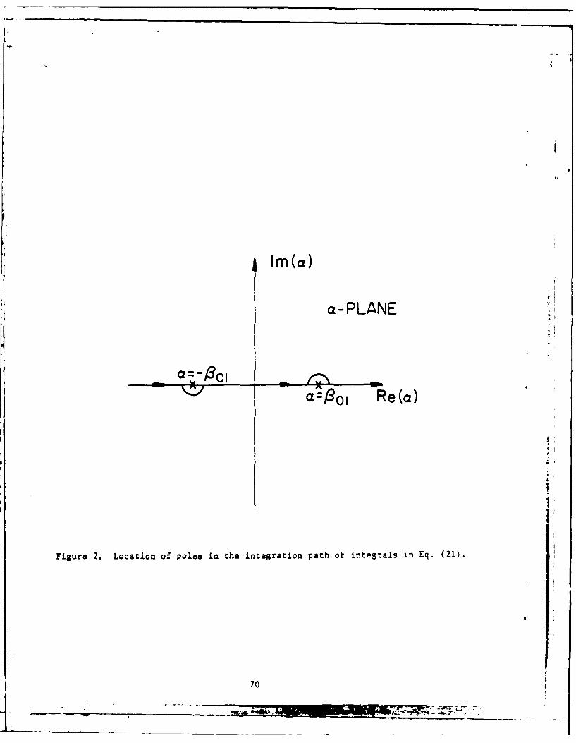
position of the poles along the integration path, as shown in Fig. 2. Each
of the integrals in (21) can be written in the following form
F(a)da 0 F(a)da + F(a)da + F(a)da +7j Res (-801)
-01 S01
- 'j Res (3 1 01 F(a)da + F(a)da
I(.) d F(.-)da + Trj Res (-01 - R es (S
0 28 00001
- 2 101 F ()d + [F(-28 1 -a) + F()] da
8011
(~01
+ JO CF(m) + F(230 1 - a)] da
+ r F(a)da + -J Res (-80) - J Res (801)28 01(24)
59

In the above equation, a bar across the integral sign means principal value
integration. The method of foldover as shown makes the new integrand remain
bounded at the singularity of the old integrand; hence, this new integral5
is easily evaluated by the numerical method. Also, since the integrand
goes to zero rapidly as a becomes large, the integration limit - can be
replaced by a large number, e.g., 14 S01. It should be noted that if the
foldover method was not used, the integral could still be evaluated numer-
ically, in some cases, but the integration limit - must be replaced by a much
larger number because of the heavy tail of the integrand, and doing so requires
increased computer time and the results are less accurate. The residues given
in (24) are easily calculated and are given by the general form
44
Res(-s 01) b(-* 01) P1 (1) P (a 01 1
with Pi (a) Pi. (a) given in (22).
(25)
4
Having discussed the evaluation of the matrix elements in detail, we can
proceed to solve the matrix equation (21) to obtain the A's. Having found
these A's, we compute f0 (a) from (15) and than calculate the scattered fields
from (2). For n-O, both ES and Ky - 0, and there is only E5 , which can bez y
written as
< y- < b) 2 in [-Y0 (b -y)
-J.U Z AP i (00
exp (-Jc z) dai(26)
60
K ____

r V 'Z -a if k>!
where Y 0/7 -= if k < i
bLet us evaluate (26) at y - b
-JkbZ0 2 *tan -
y 2 4 i P i (a) exp(-Jaz) dac (27)
2J
Since the scattered fields on both sides of the beam equalizer are given by
(27), we can compute the transmission and reflection coefficients by
normalizing these scattered gields to the incident field given in (I).
The reflection coefficient R can be expressed as
s
ER - b
x z<O
-r exp(JO 01z) 2Z Ai 2j Z Resi(¢) ] (28)
4 h01 i-0 m-., 3,5,... jwhere the poles are given by
-8 -- ,~..:'; > .C.'.) k2
1 01 b m>3 b
and the residues at these poles are given by
4 Pi(-801) exp (jz80 1)
b2 (-01)
61

4 P (jX exp (X z)Res(m Res( ) * i(J) m >M3>3
b ( xm)
with xm b-
Xx 2
P - + )] exp tx 2
c (. ' (c
P2 (jx m) - exp ( ) ( Xm
and I0, II are modified Bessel functions of the first kind. In deriving (23),
the integral in (27) has been evaluated by the residue theorem with the
contour closed in the upper half of the a-plane. By the same token, the
transmission coefficient T can also be obtained, except this time the contour
is closed in the lower half of the a-plane.
E s bx b
Ex z>O
-if exp( Q a01z) 2- e4h0 1 r Ai [-2wrj Z Res i ,m (29)
401 :
where the poles are given by
'.l =01 b
u-i 62;~m>3 b I ( k
4 .......'
Kn
and the residues at these poles are given by
4 Pi (B0) exp (-JB01 z)Res i( I b b2 o0
4 P .(-ix m) exp (m )Resi( ) U Resi(-JXm) 2 m > 3
b 2(.Jx ×m
with X _.b
P (-JX ) t.. exp [-xm(c+d+ i)] exp ['m
Y Xmc. c
P1 m e2 0t ( ,.)
p2 (-jxm) - exp (-Xm c jI )
and l0, 11 are modified Bessel functions of the first kind. Nmerical
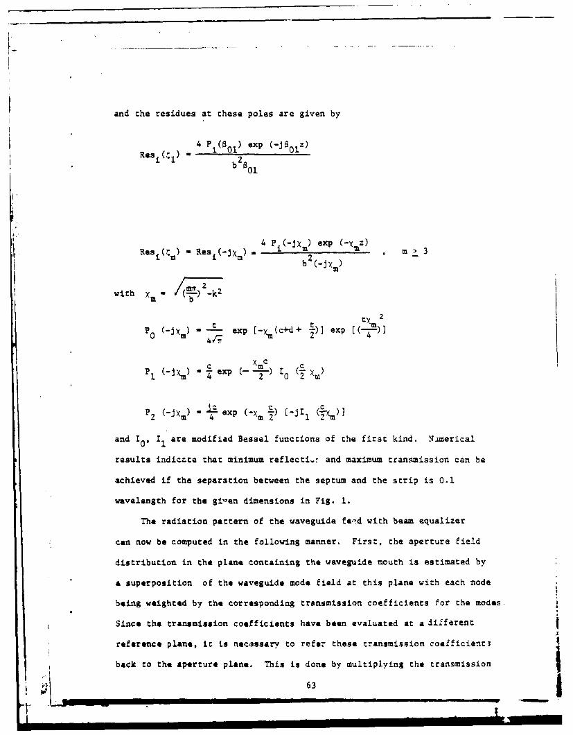
results indicate that minimum reflectL-7 and maximum transmission can be
achieved if the separation between the septum and the strip is 0.1
wavelength for the gilen dimensions in Fig. 1.
The radiation pattern of the waveguide feed with beam equalizer
can now be computed in the following manner. First, the aperture field
distribution in the plane containing the waveguide mouth is estimated by
a superposition of the waveguide mode field at this plane with each mode
being weighted by the corresponding transmission coefficients For the modes
Since the transmission coefficients have been evaluated at a different
reference plane, it is necassary to refer these transmission coefficienti
back to the aperture plane. This is done by multiplying the transmission
63 I I I1

coefficients by an ippropriate correcting factor, which is a phase factor
for a propagating mode and is an exponential factor for an attenuated
mode. The radiation pattern is then obtained by the familiar Fourier
transform relation between the far field and the aperture field. For TE
modes, the far fields are given by the following expressions [2]:
E -- 1/2 (lab)2 sine nm nm3 k2 (1 + -+ - cosa + R (1 - - - cosa)]
2X r k
n 2 (m7 2[(-sino) -b --COS) T (0*
anm
1/2 )2
E - - ( () (lab) sini sin6 coso~2 X3 r
S Scos + m -+ R (Cosa - m ' (e,) (30)
k k nm
si(2a sine coso + -7sin(-- sine sin, + -
2 2 2 2
L:a ieCOO ~ :r ie sio -_i
exp { -j [kr-- sine (a cos -+ b sino) - (n+m+l) .1 }2
where (r,C,.) are the conventional right-handed spherical coordinates. The
total radiation pattern is then obtained by a superposirion of these
Individual mode patterns with the appropriate transmission coef.ficients
referenced at the aperture plane. Computed patterns and numerical results
are presented in the next section.
64I'.--...__ ___ _ __ ___ ___ _ _ ___ ____ ___ ___ ___ ___
__________I____________l____-_

III. Computed Results
The performance of the square waveguide feed with beam equalizer
whose dimensions are shown in Fig. 1 with d -. lA is evaluated over a
frequency band of operation. The value for c has been chosen experi-
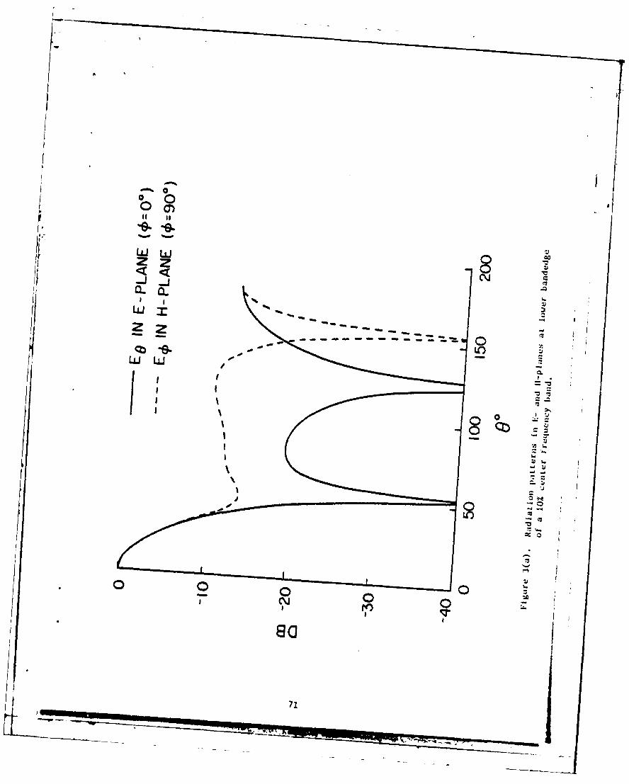
mentally to be 0.23\. The computed radiation patterns in the E- and
H-planes are presented in Figure 3. The beam equalization is quite
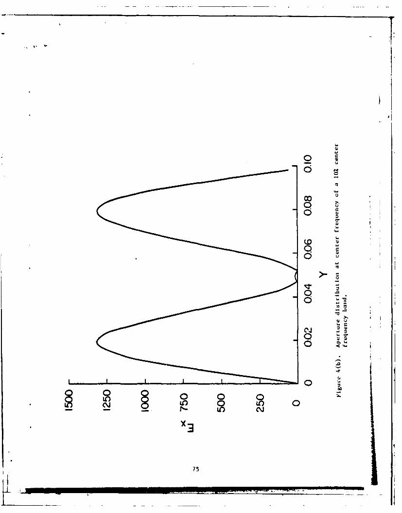
satisfactory over the entire band. The corresponding aperture field
distributions are shown in Figure 4. Looking at these aperture dis-
1tributions, one can explain how the beam equalizer works. It goes
as follows. The aperture distribution for the E-plane pattern is
uniform which gives a familiar (sin x)/x type of pattern. The H-plane
pattern is due to a cosine-taper type of aperture distribution if there
is no beam equalizer present. Hence, the beamwidth is larger than that
of the E-plane pattern for a square waveguide aperture. However, the
introduction of the beam equalizer forces the H-plane aperture field
to vanish at the center of the aperture, which makes the field distri-
bution look more uniform. Hence, the main lobe of the H-plane pattern
narrows to achieve the beam equalization effect in the E- and H-planes.
The pattern is mainly determined by the septum; the post is present for
1These curves are generated using only the first three terms in themodal series expansion. While the boundary conditions at the wave-guide walls are satisfied perfectly by definition of the modal func-tions, there appears to be a small residue of Ex at the septum inthe middle of the waveguide. This residue is solely due to thetruncation of an infinite series to a finite number of terms. Perfectcancellation can be approached when more and more terms are used inthe series.
65

impedance matching. The computed reflection coefficients over the
frequency band are shown in Table 2. If the post is absent, the reflec-
tion coefficients will be much larger than those shown in Table 2.
IV. Conclusions
A septum and an impedance matching post used as a beam equalizer in an
open-ended waveguide-feed for reflectors used in satellite communications
systems have been analyzed by using a spectral domain approach. The
computed radiation patterns in the E- and H-planes, as well as the
impedance match results, have been presented in the paper. The performance
of the beam equalizer over the entire band of operating frequency has
been evaluated. The results indicate that the E- and H-plane principally
polarized patterns are equalized extremely well over the entire frequency
band of operation and that the impedance matching is also satisfactory.
Acknowledgement
The authors are grateful to Dr. C. C. Han and Dr. Y. M. Hwang of
Ford Aerospace Company for bringing the problem to their attention, and
for helpful suggestions and technical guidance. This work was sponsored
in part by Ford Aerospace and Communications Corporation and in part
by Office of Naval Research under Grant N00014-75-C-0293.
References
[] R. Xittra and T. S. Li, "A spectral domain approach to the numerical
solution of electromagnetic scattering problems," AEtJ, vol. 29,
pp. 217-222, 1975.
(2] S. Silver, Microwave Antenna Theory and Design, M.I.T. Radiation
Laboratory Series, McGraw-Hill Company, New York, 1949.
gi - - - --- _ _ _

Table 1. BASIS FUNCTIONS IN SPATIAL AND SPECTRAL DOMAINS
Spatial Domain Spectral Domain
t2 2
P (z) exp(-( 2 P (as) t e xp (-j a(cd+ ej] xp(~E
I. I2
1
pl(z) - p() c J (S)/1_(c2c22 " a) exp (-Ja-rf) 0o2
z ,- c/2
p2 (z) ,= c/2 P2(a) = i. exp (-*j 7) Jl( 7 )c/22
____c cn 12(
ql~z) = /1 z + C/2)q( "ex C- ""
c /2 '- C ¢
(2 ) Q1(a) - exp (-j 7) -S--P2c/ 2_2_4_2_1_q2(z)~~~ + c/2 Q()- C~ci2 c
2
J 0' J 1, ad J2 ae Besel funcions of he first kind and of order zero, one, and
o, correspondingly.
67
_iT

TABLE 2
REFLECTION COEFFICIENTS OVER THE FREQUENCY BAND
d - O.1X
Frequency (GHz) Reflection coefficient R VStJR -i-! RI
3.75 1.2729/10.2 5 1.751
3.85 O.1879/-134.90 1.463
3.95 0.1071/-142.02" 1.240
4.05 0.0358/-167.87 1.074 j4.15 / 0.0442/73.10 1.092
68
I ........
POT SEPTUa
'- I - b/2
- b/2
0 z z x
LONGITUDINAL-SECTION CROSS-SECTION
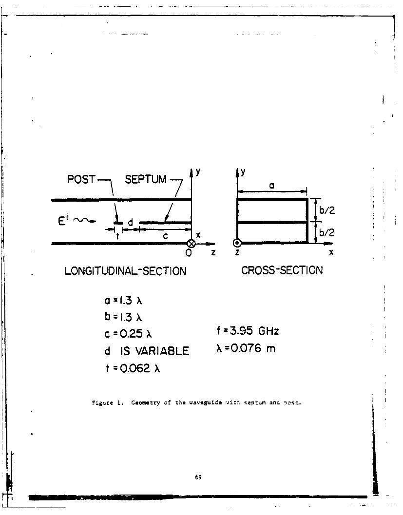
a=I1.3 X
b =I.3 Xc=O.25 =395 GHz
d IS VARIABLE X =0.076 m
t =0.062 X
F.gure 1. Geometry of the waveguide :ith septum and nost.
69
L _____gen-
Im(a)
a-PLANE4I
R a:- o -Re(a)
iI,
Figure 2. Location of poles in the integration path of integrals in Eq. (21).
70
< <J j H
CLILLa'
co IIO
L , LL)
LJJL7JZZ 7z
00
I~
rrC
I-'71

00 0)
0 C)j
z z
LL
wJ LO)
zz
LLJLI..J .4-
01w
ap dop 8
I~ r4 2-
72.d
SIo ARVIW..
.~ ~JA

_~- 0 I.
00
W a. a.
0 J-
za -
w-
doa
C~CU I-.
730
LJA

coi
U4
om
Ul0
X3Q
La'
0
_00
oo00
'x -
75.
0
C~C
0
00 0 o
co C~i
76
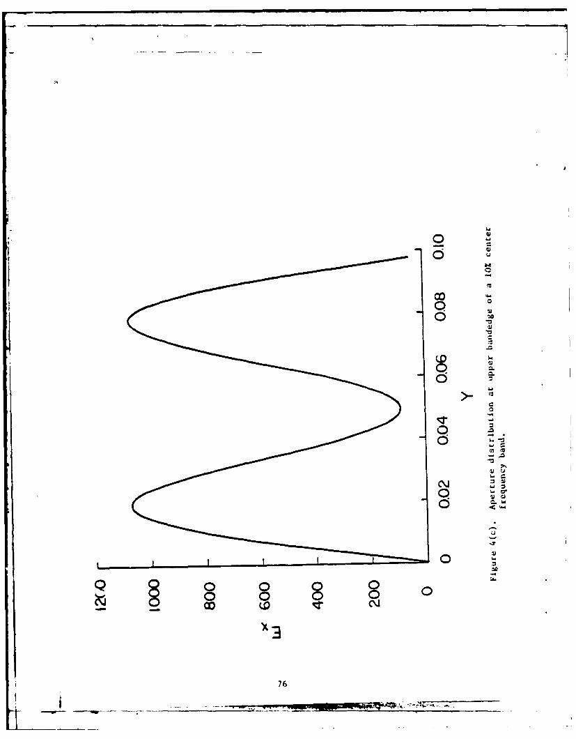
APPENDIX D
A SPECTRAL-ITERAT'ON .A2PROACH FOR ANA-TYZING
SCATTERING FROM FREQUENCY SELECTIVE SURFACES
by
CRICH-USING TSAO
RAJ MITTRA
I

ABSTRACT
In this paper, we apply a novel technique, called the spectral-iteration
approach, for analyzing the problem of scattering from periodically perforated
screens which find useful applications as radomes, cptical filters, artificial
dielectrics, and so on. The formulation is carried out in the spectral domain
where a set of algebraic equations is obtained directly for the spectral coef-
ficients of the aperture field distribution (or the induced current density)
rather than via an integral equation formulation. These equations are then
solved simultaneously using an iterative procedure developed in this pape.
that circumvents the need for matrix inversion. Because the matrix solution
is avoided in the spectral approach, it is capable of handling large aperture
sizes in a computationally efficient manner. The efficiency of computation
results from the use of the FFT (Fast Fourier Transform) algorithm which is
employed in the derivation of the algebraic equations and in the iteracion
procedure. A unique feature of the spectral-iteration approach is that it
has a built-in boundary-condition check which provides a reliable indication
of the accuracy of the solution. This paper also shows that the spectral
domain technique can be applied to even a wider class of geometries, e.g.,
the step discoczinuity in a waveguide.
The work was supported by the Office of Naval Research, ContractN00014-75-C-0293.
1. NTMDUCTION
Periodic structures such as arrays of conducting strips or periodically
perforated screens which can be either free-standing or printed on dielectric
substrates (see Fig. 1) have frequency selective properties, and find many
applications as artificial dielectrics, optical and quasi-opcical devices,
and dichroic surfaceb for antenna reflectors and radomes.
Conventionally, the problem of electromagnetic scattering from these
periodic structures is attacked using the mode-matching procedure employed
in conjunction wi-th the method of moments. A description of this procedure
can be found in a number of papers on the subject by Chen [I], Lee [2], and
McPhedran and .aystre [3]. Though this method works quite well in :he Low-
frequency region, it becomes prohibitively costly f noct impraccical ac the
high frequency region where the aperture size is one to to wavelengths, or
larger, because the matrix size required for an accurate solution oeczmes
prohibitively large and the numerical computation becomes axtreelv time-
consuming and costly. The high frequency techniques, e.j., GTD, cannot be
applied to circumvent the above diff'.culty either, because the complex
geometrical configuration of :he structure does not lend itself to :he ray
formalism of CTD. Ia this paper we incroduce a new technique based on :he
spectral domain approach which provides an efficient and accurate solutiln
to the gracing problea described In this paper.
As a first step, the now approach begins with :he formulation of :he
prooblm in terms of an integral equation in the transform domain. 7he
standard procedure for deriting the integral equation f r :he unknown 2
aperture field (or the induced curren) ts sc:ll followed; however, in Lhe
transfar- donaim :ne convoltrion form of :he integral equation becomas
_ _____ I

INCCIDNT 01EE RI - MWEtAL
SU P.S TR ATE
soE-4 ~ ~ :-wit

an algebraic one. Furthermore, because of the periodic mature of the
structure, the transform naturally takes the form of OFT (discrete Fourier
trausform) which can, in turn, be efficiently evaluated using the M (fast
Fourier transform) algorithm. The transformed integral equation is
subsequently solved, using an iterative procedure, simultaneously for the
aperture field and the induced current. It is evident that the method
avoids the time-consuming steps of evaluating the matrix elements and
their subsequent inversion. More importantly, the problem of storing and
handling over-sized matrices is circumvented even at high frequencies,
where the number of unknowns can exceed the figure 2000. Xn added feature
of the method is that a built-in step in the iterative procedure provides
a convenient measure for the boundary condition check, a feature not
readily available in conventional approaches. Finally, the convergence
of the iterative procedure is enhanced by combining it with a variational
approach in a manner explained lacar. For completeness, "we mention that
an approach similar to .he present one has been used by Xitt.a and Ko r.4
in studying the single-scacterer (as opposed co :he periodic gratng)
problem. The above authors have used the GTD solution as the zeroth order
approximate solution and have also employed an iterative procedure to
generate the final solution. However, to-date this procedure has not been
applied to the ;rating problems being considered in this paper.
In the next section, we present the formulation of the periodic
$racing problem. In Section 3, we describe the iterative procedure. In
Section 4 we illustrate the application of the technIque to a number of
practical geometries. ?nally, we demonscrate In Section 5 chat che
approach is useful for a class of closed-region problems, e.g., "davejuide
disconcinuities. A brief sumar-y of the aper is included in Section i
and some conclusions are presented.
81
4... ..... _ _ _ _ _ _ _ __ _ _ _ _ __ . 4._
I. FORMULATION
For the sake cf illustrating the spectral approach, we consider the
problem of a uniform plane wave scattered from a free-standinS periodically
perforated conducting screen shown in Fig. Z. However, the method of
solution is easily and conveniently extendable to the case of a screen on
a dielectric substrate.
Due to the periodicity of the structure, the electric field on either
side of the screen can be expanded in terms of the Floquet space harmonics.
Using the ej' time convention (suppressed), we can write
i,, rE XiziEx -V= e forz> 0,
u • i-nnjn% o
and
U --
x~ =n 0,-.- ...
a or z 0
+ +'
where £represents the incident field, (XM Y )n and (X, Y )n are the
reflection and the transmission coefficients of the Floquet's harmnonic
modes, respectively and 'an stand for the Floquec mode functions, given
by
-exp j(u 5x vy)
where
u -T k sin 8 cos b20 a
-' 0,±I ,:2,
82

yx
Li k
?i.ure 2. Froe-standing, periodically perforated screen illuinated
by a pLane wave propagating in k direction.
83

v =27n _--m cot - k sin i sin 2ma c a
4
and
[jJ[k _ (u2 + v2 )]l.12 i f . +20 ia mu 20 m
1-(uV2 _ k 1/2 if k2 < (u2 + v )
20a m 30 3
The z-component of the E-field can be derived from (1) using the divergence
theorem.
Enforcing the condition that the tangential field is continuous across
the interface, we obtain
.4 - -mX = X m Y when m 0 0 or a 0 0
and
X + Ei I - Y + + Ei . Y -
00 x 0o 0 0 F 00
The K-field in the region z > 0 and z < 0 :an be derived from
Equation (L). Evaluating the 11-field at z - 0- and z - 0 , subtracting
the expression for one from the other, and making use of the recuiremenc
that the tangential components be continuous across the aperture, one
arrives at the equation:
3M - ' H i-j.U + .2 y) " for z Ii0
- M A an) t~~mn X)(2)
where i( is the incident H-field,
is the induced current on the surface.
A - u2 .v /yz,,
. .# m m| u -. ,
33 a v M n- YM
C m u2 /Yan ma 30 Mu.
84
In (2) we have used the notation that for a function f(r) defined on the z - 0
plane, where r is the position vector on chat plane, the truncation operator
i.s defined by
( 0 for r on the conducting surface
• f(r) for in the aperture
and
aw;)) - f(') - 3<f- ))
the obvious dentiy 9(7) - I and that ((z 0 ) !(:h -)]
have also been used in deriving (2).
Un ike the integro-differencial equation in the conventional method,
which applies only in the aperture (or strip) region, (2) is valid over
the entire surface. The price paid for extending the equation to the full
range is the introduction of an extra unknown j. However, as we will soon
see, the additional unknown I can he solved for along with the aperture field
using the iterative procedure discussed in the next section.
85
I i nLI

III. ITERATIVE POCED3RE
The summation involved in (1) and (2) can be readily identified as the
DFT operation. Let F be the operator representing the DFT, and 116C E
represent the tangential electric field in the transformed domain.
Identifying (X-, Y_) In (2) as the Fourier coefficients of ' and
writing G for the matrix
C
we can write (2) symbolicall7 as
F(A t . + , (3)
•here the subscript t indicates the tangential components, and it is
understood that all the quantities are evaluated at z - 0.
:f the Induced current were available, the solution for . could
be immediately obtained by invoking (3) and by using
t*0(F 1 (-Ht + 9())).() I
:n practice, however, 1 is the unknown to be solved for, together with E
and hence (4) cannot be used directly. Instead of using (4), a recursive
th !(n+l) trelation between the (a + 1) approximate solution E( ad the a
approximation () is now derived and the two unknowns E and J are solved
for siL-ltaneously using an iterative procedure.
To derive the recursion formula for E), we begin wi:h '3), which
relates j a(n) 4 (), and %mite
86
m mm , ma m ! l l I l.m :

.-() i (5)
Subst tuting (5) into (4), one obtains
a~~~~ (a(W~F(* )) (6)C~ ~ ~ G;+ F(Et +Ht(6
Equation (6) is the desired recursive formula. 3tfore inserting - into
(5), we adjust its amplitude by multiplying with a scale factor K, computed
according to the variation expression
K. * <n) TTn)) (7)
t , t
where <f, =aperturefS-da.
Equation (7) is obtained by applying the one-term Galarkin's method
to Equation (3) using ;(n) as the testing function. It is apparent thatt
K - I when !(n) is the exact solution. K, therefore, also provides an
indication of the accuracy of the a h iterated result in a weighted-
average sense.
In the following we proc( 4d to outline an iterative procedure for
solving (6):
1. 3egin with an initial estimate 1(o). The amplitude of
( is to be properl7 adjusted using the scale fac:or
K determined from Equation (7).
2. Compute E , the discrete Fourier transform of i(0)
Thi3 step can be carried out efficientl7 using the
.TT algorithm.
3. Compute G.E0t
87
I
4. Obtain the DFT of G() using yFT.
5. Subtract -H from the result obtained from step 4.t
-(0)This gives the zeroth-order approximate solution J
Generally, the approximate solution for 1 obtained in
this step has non-zero values extending beyond the
conducting surface. The satisfaction of the boundary
condition for the induced current can thus be verified
thby checking how well the a approximation for the
currant is confined to the conducting surface.
6. Add -' to S(0) obtained in the last step, and take thet
inverse DFT of the result using iTT.
7. Multiply G by the result obtained from step 6.,
obtaining E()
S. Take the inverse transform of E to set .Thet
exact solution for Et should have zero value on the
conducting surface. This criterion sertes as a boundary
condition check for the approximate solution E
obtained in this step.
9. Repeat the whole procedure, as necessary, using 3(f-(t
to generate the next higher-order solutions 1(1) 3nd
!(Z) until convergence is achieved.t
In the following two sections several examples are presented .o
illustrate the application of the technique described above.
88
V. SCATTERING FROM GRATINGS AND GRIDS
Let us consider a iree-standing, strip grating structure illuminated
by a normally incident uniform plane wave as shown in Fig. 3. Let the
incident E-field be polarized parallel to the edges of the strip (an
H-wave).
The formulation for this problem is given by Equation (2). The
iterative procedure discussed in Section III is applied to solve for
the tcangential aperture E-field, Et, and the induced current density,
..
Figure 4a shows the incident E-field truncated in the aperture, which
is used as the zeroth-order approximation for E, i.e., i(Ki).tt t
The !(0) derived from ) is shown in Fig. 5a. has significant
non-zero values extending Into the aperture region. This could be expectedbecause of the crude initial estimate made for Er(0). Figure 3b shows
obtained after one iteration. Observe the significant improvement achieved
with just a single iteration even though the zeroth-order approximation for
?(0) was rather crude. Higher-order solutions for i(n) and (n), obtainedt t
via further iterations, are shown, respectively, in Figures -b to 4d and
Figures 5b to 3d. The rapid convergence and che accuracy, which is verified
by the boundary condition check of the solutions, are well-demonscraced
in these figures. The induced current density J also shows the expectae%.
edge behavior, i.e., it becomes large at the edges as it should for the
Incident i-wave.
Figures 6 and 7 show the solutions for E C and J obtained after
four iterations when the iratings are illuminated by an obliquel7 incident
plante wave with an Incident angle i - 30' and with the q-field polarized

zVa 1.4X
tb=O.6a .....
b b
Figure 3. Free-standing gracing Ulluminated bv a normaly incidenta-wave.
90
!A

n
L
Jo ~2 -a
-aI~ -0
-- 4
0
I ~1J.~ ~J1- -
- ~.J- - - - 0 0 0 00 1~
0W/A ~7,3I
- -a
~J0_____________________________________________ 1-* I I 0
__________________________ ~4~
-4~ '~2 ~z
- o
________________________________I
W/A I(OI~
91
-S
AD-A1O5 664 1 LLINOIS UNIV AT URBANA ELECTRONAONETICS LAB F/G 0/INVESTIGATION OF TRANSFORM TECHNIQUES FOR SOLVING ELECTROMAGNET--ETC(U)APR 81 S V LEE. R MITTAA. W L KO NOOOI-475-C-O293
UNCLASSIFIEO UIEM-81-3 NL2 2llllllllIIMl22fllfffllfffllff
IlllllllllllluIImI

Is,
i r I
I.3J~UIC ,~
I I I
- - - - o o0
W/A I
:a: -
I~ .~
Is,d
--
*-:fl
0 ~ B'~-R %~ .- '- *,.I 0 1'
-20 IIW/A
92
I-
. .
d x
I',=
o . . .. o
w /'.j ,1, r
- -
-P"
, 4r' 4
93.IoA
I I 0
-, 0,, ,,0' i

'
a 6
... 'a
-I
-A
tAt
,~9 .. -
' ~-I-,.
, , i 1 i I I - .
P......
C
Ila,
I P ; I I I I i ,
94

IdI
A '
I-c
-a 3
W/'7 OI V1
95H

parallel to the edges of the strip (in the E-wave case). Again, the boundary
conditions are satisfied extremely well by the results, and the anerture
E-field also shows the expected edge behavior for the incident E-wave.
Next we consider the scattering from a free-standing conducting grid
illuminaced by a normally incident plane wave. The geometry of the problem
2is shown in Fig. 8. The aperture area is approximately lOX whereas the
cell area is about 44X2. Th. initial approximation for E is still chosen
to be the truncated incident field, and the dominant component of the
tangential aperture E-field is shown when the incident E-field is polarized
In the 7-direction.
For all the computations in this section, 32 tarms in the Floquet
expansion functions are used in representing the unknown fields along
each of the two dimensions. This leads to 211 equivalent unknowns "o be
solved for. The computation time, however, required for deriving the
solution is quite moderate (5 - 6 secs. of CPU time on the CDC Cyber
175 System). Clearly, any matrix method dealing with such a large number
of unknowns will be totally impractical.
96
o 0000 000
ujN
22
10- - -n.- 2SV
(A3 '4V
'L-~4
98 9 ~ -~ -
11: 3on.\ NOV A
L~J * 1097
V. GENERALIZATION TO T'4O-REGION PROBLEM
In this section, the iterative technique is further generalized to
analyze a wider class of geometries. These geometries are characterized
by the feature that they comprise a junction of tvo or more regions of
dissimilar dimensions. An open-region type example is a corrugated surface
which can be thought of as a junction of two regions, viz., the infinite
half-space and a periodic array of short-circuited waveguides. For the
sake of simplicity, a closed-region type problem - a step discontinuity
in a parallel-plate waveguide - is considered in this section. The geometry is
shown in Figure 9. The incident field is a TE mode wave. The formulation of
this problem can be found in the literature, The integral equation is given by
rb rbE (z')KCx'x')dx' Eo -(x')K+(xx')dx' - 2H' (8)
for 0 < x < b, z 0
where S Is the unknown aperture E-field,7a is the Incident H-field,x
sin " x sin --- X'(x,x') - s M x s n a
=- a a
mW a2 Z ..z2 air < 2z
,m--
a ) . k2)LI if k' <
aa
and
-j (k-7 (af) 2) 1/2 if k (;>-)r
,a ai 2 2 1/2 iLb
98
.. . . . . . . . . .- --

wh a
F igurs 9. Seep diScon:~u±'y i i a parai.lel-plate :¢avegudewtch a TE inclden wave.
99
.. p.I
Note that Equation (8) is defined in the region 0 < x < b. To apply the
iterative technique, it has to be extended to the full range 0 < x < a.
This is achieved by introducing an extra unknown function J(x), and the
extended equation takes the form
a
E7(x')k(x,x)dx' - .x')ex,x')d' + 8(-2H') + O(J(x)) (9)0 o
for 0 < x < a
where for any function f(x)
9(f(x)) - f(x) if 0 < x < b
- 0 if b < x < a
and
~~(f~x)) -f~x) -(f(x))
A recursion formula relating the (a + ) th order solution Z(n+ ') to the
a solution E can be derived via a procedure similar to that developedy
in Section I1. The formula is
(n+'l). K- .a , (n)
Equation (10) is now solved using an iterative procedure similar to
that developed in Section II1. The integrations in (10) can again be
carried ouc using the FM? because of the characteristic nature of the
kernels. Figure 10 shows the aperture E-field distribution at the
discontinuity. The initial approximation for E is taken to be they
incident field truncated in the aperture.
'he result is obtained in three iterations with 32 expansion functions
used in representing the unknown field. We note that the boundary condition
on £y, viz., that it vanishes at the edges, is satisfied by :he iterated
solution. 100
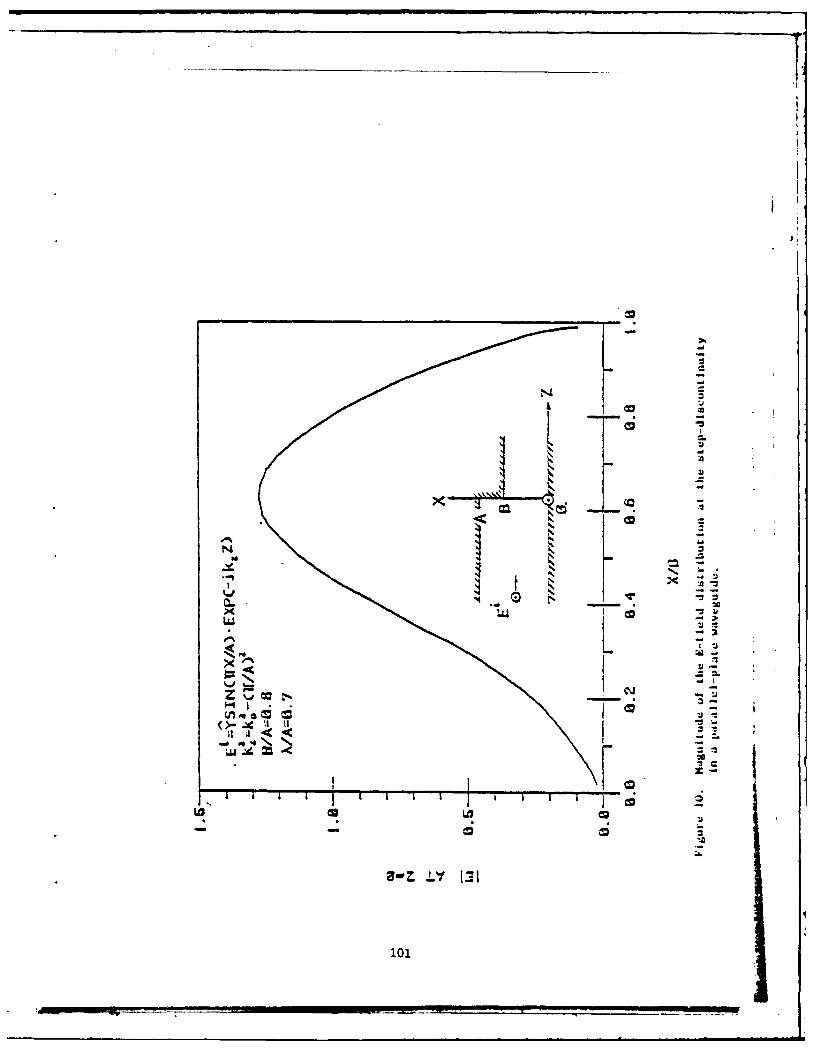
IzI
Zj
3-Z~~ -* 1:
101-

-I.
VI. CONCLUSION
In this paper, an iterative cechnicue applied in the spectral domain
has been employed to solve the problem of scattering from two-dimensional
periodic structures. Applications of the technique have been illustrated
using a number of examples. This spectral-iteracion technique has been
found to be very efficient for two reasons: (i) it is applied in the
transform domain, where only algebraic operations instead of convolution
integrations are involved, (Ii) the use of the efficient FFT algorithm,
which is employed to carry out the algebraic DFT, is natural to the
proedure. The technique also has a built-in boundary condition check
which verifies the accuracy of the icerated solution - an important feature
mot available in conventional methods. %rthermore, the induced current and
the aperture field are solved for simultaneously which is another unique
advantage not available in other methods. Finally, as mentioned earlier,
this technique is particularly appealing in the high frequency analysis
where the moment method has unsurmountable difficulties and other asymptotic
techniques fail. Before closing, we would like to point out that at the
lower end of the frequency scale the effect of mutual coupling among
adjacent apertures (or conducting strips) becomes significant and
the field distribution in the aperture begins to deviate substantially
from the incident field. Consequently, it becomes difficult to choose
a good initial approximation for the aperture field, particularly the
cross-polarized component, such that a rapid convergence of the
iteration process is ensured. Fortunately, however, an alternative
method also developed by the authors [5] and called the Spectral-
102
04.,l
Galerkin approach, has been found to be well-suited in the low
frequency region. This approach is based on an application of the
Galerkin's method in the spectral domain. It selects the proper
expansion functions which are analytically Fourier transformable
and which satisfy both the boundary and edge conditions for the
unknown fields. It has been shown that the required matrix size is
much smaller than in the conventional schemes and the numerical
computation is very efficient.
1031

26
REFERENCES
[1] C. C. Chen, "Transmission through a conducting screen perforatedperiodically with apertures," Microwave Theory and Techniques, ,vol. 18, no. 9, pp. 627-632, 1970.
[2] S. W. Lee, "Scattering by dielectric-loaded screen," IEEE Trans.Antennas Propagat., vol. 19, no. 5, pp. 656-665, 1971.
[3] R. C. McPhedran and D. Maystre, "On the theory and solar applica-tions of inductive guides," Appl. Phys., vol. 14, pp. 1-20,1977.
[4] W. L. Ko and R. Mittra, "A new approach based on a combinationof integral equation and asymptotic techniques for solvingelectromagnetic scattering problems," IEEE Trans. AntennasPropagat., vol. 25, no. 2, 1977.
[5] C. H. Tsao and R. Mittra, "A Spectral-Galerkin analysis of thescattering from frequency selective surfaces," to be published.
104
I
104

APPENDIX E
A SPECTRAL-ITERATION TECHNIQUE FOR ANALYZING A
CORRUGATED-SURFACE TWIST POLARIZER FOR SCANNING REFLECTOR ANTENNAS
R. Kastner and R. Mittra
ABSTRACT
In this paper we present an analysis of the corrugated-surface twist
polarizer which finds application in the design of scanning reflector
antennas. We employ the spectral-iteration technique, a novel procedure
which combines the use of the Fourier transform method with an iterative
procedure. The first step in the spectral-iteration method is the con-
version of the original integral equation for the interface field into a
form which is suitable for iteration using a method developed previously
[5]-[7]. An important feature of the technique is that it takes advantage
of the DFT type of kernel of the integral equation and evaluates the
integral operators efficiently using the FFT algorithm. Thus, in contrast
to the conventional techniques, e.g., the moment method, the spectral-
iteration approach requires no matrix inversion and is capable of handling
a large number of unknowns. Furthermore, the method has a built-in check
on the satisfaction of the boundary conditions at each iteration.
The work was supported by the Office of Naval Research, ContractN00014-75-C-0293.
105
rl
A SPECTRAL-ITERATION TECHNIQUE FOR ANALYZING ACORRUGATED-SURFACE TWIST POLARIZER FOR SCANNING REFLECTOR ANTENNAS
I. INTRODUCTION
This paper presents an analysis of the corrugated-surface twist
polarizer, a device which is used to rotate the polarization plane of
an incident wave by 90*. Such a polarizer finds applications in scanned
reflector antenna systems (Fig. I) where a rapid mechanical scanning
is achieved by the movement of the passive, light-weight polarizer [1].
The feed horn radiates a horizontally polarized field, which is reflected
from the "transflector" radome, comprising horizontal strips, onto
the twist polarizer. The twist polarizer is so designed that upon
reflection from the polarizer the horizontally polarized incident wave
is changed into a vertically polarized reflected wave to which the
radome is virtually transparent. Thus, the radome also serves as a
collimating device and the antenna is compact and light weight.
A common type of twist polarizer comprises a set of thin metallic
strips or wires placed on top of a dielectric substrate, which is approx-
imately X/4 thick and is backed by a ground plane [1], [2], [3], [8].
In this paper, we investigate the design of an alternative configuration
which also can be used for rotating the plane of polarization of an
incident wave, viz., the corrugated-surface polarizer. Its basic
mechanism can be explained very simply [41 by noting that if the period
of the grooves is sufficiently small compared to the wavelength, a plane
wave polarized parallel to the grooves will be reflected essentially
from the outer surface of the polarizer, while a vertically polarized
wave will be reflected from the bottom of the grooves, which results in
a differential phase delay corresponding to twice the groove depth.
106
Thus, if the incident field were polarized at 450 to the direction of
* the grooves, the horizontal and vertical components would have equal
amplitudes and phases, and a phase difference of 1800 will be produced
by a groove depth of A/4. Unfortunately, the cell size is typically
not small at millimeter waves and the above result is not sufficiently
accurate for designing the polarizer.
The spectral-iteration approach (51, (61, [7], presented herein,
provides a method for efficient and accurate analysis of the corrugated
twist polarizer. Unlike conventional moment-method and mode-matching
techniques, the spectral iteration technique requires no matrix inversion
and, consequently, large cells can be analyzed without any difficulty.
Furthermore, the accuracy of the solution can be conveniently checked
at each stage of the iteration. This is done by determining how well
the solution satisfies the boundary conditions and by verifying the
conservation of energy.
10?
II. GENERAL FORMULATION
Let the corrugated-surface twist polarizer, shown in Figure 2, be
illuminated by a plane wave with a wave-number B in the x-direction.
Because of the periodic nature of the geometries, phase-shift walls with
period a can be placed in the external region (z > 0) of the structure
and the problem can be reduced to that of solving for the discontinuity
between a waveguide with these phase-shift walls and the short-circuited,
parallel-plate waveguide of width b in the interior region (see Fig. 3).
In two cases, viz., the TE polarization (parallel to grooves) and the
TM polarization (perpendicular to grooves) need to be solved for
individually to obtain the differential phase shift between the two
reflection coefficients. For an incident wave polarized at 45* to the
direction of the grooves, the plane of polarization will be rotated by
90* if the differential phase shift between the two reflection coeffi-
cients is 180*.
The spectral-iteration approach for this problem is based on the
fact that the Green's functions for both the external and internal
regions are expressible in terms of Fourier-type series. Thus, in each
of these two individual regions the integral operator that relates
E- and H-fields is exactly invertible. Denoting the operator for the
external region, which is a cell bounded by the phase-shift walls, by
L_, and the operator for the inner region by L+, we have the general form
L * + L + 2Finc (1)
108

in which F iccorresponds to the electric field incident from the outer
*region and p is the unknown magnetic field in the aperture. (If, instead,
the unknown is the electric field in the aperture, then F is replaced by
the incident magnetic field.)
109
III. TM POLARIZATION
In order to illustrate the application of the spectral-iteration
technique, we consider the case of the twist polarizer illuminated by a
TM polarized wave. (The TE case is discussed later.) We choose to
be the unknown electric field in the aperture and derive the following
integral equation via the usual formulating procedure of matching the
interface fields.
1o j8n)XI 2j(1 ) incf p(x')e e a dx' +H(x) 2H (xa /'- T
0 a (2)
whereS b
b I_ _ -(X')cos x' cos - xdx', O<x<b
0(x) 0
h(x) b<x<a
(3)
and I-JBx,,
H eC) (4)
h(x) is the unknown magnetic field outside the aperture where the
boundary condition on the conducting wall requires q to be identically
zero. For the sake of convenience, we have suppressed the factor -jwp
in H and Hinc. Equation (2) is of the form of (1).
110
The operator corresponding to the external region
L (.)+n2 (x'x)
D ( + n - -
0 a
is invertible in the range 0 < x < a, whereas the inner operator
2__ ___ ___1 mir ,' m
L' cos a- x cos - x dx'(.)(6)n+o cotb)2 n0r b b
ot (P))2
has the same property in the range 0 < x < b.
The iterative procedure for solving (2) will now be given:
1. Assume an initial p(x), such that P(x) - 0 in the range
b < x < a.
2. Evaluate L_(4) in the range 0 < x < a via a two-step FFT.
3. Compute 2Hin c - L_4 to obtain H.
4. Evaluate L (H) using a two-step cosine FFT transform
over the portion 0 < x < b to obtain the next estimate for
in the aperture.
5. Add zeros over b < x < a and return to step 2.
It is evident that the procedure requires the evaluation of L- 1 ,
/2 _ir2which in turn requires multiplication by the factor cot(, -(-) d).
This factor becomes small in the neighborhood of d - X/4 and for m - 0
and, hence, presents no difficulties in implementing the iteration
procedure. Had we chosen 4 to be the electric field, a similar iteration
procedure would have required the multiplication by the factor
Il 11
tan(Yk 0d) and the process would have diverged. Thus, it is
important to choose the proper unknown for p when using the iteration
procedure.
The reflection coefficient is computed at each step of the iteration,
and convergence is achieved when its absolute value tends to 1. Since a
reflection coefficient close to +1 is expected, a uniform distribution may
be chosen as an initial guess. It is found that, even with this initial
choice, convergence is attained within three or four iterations.
112

IV. TE POLARIZATION
In this case, the magnetic field distribution is chosen as the
unknown O(x). We have the following integral equation:
b j (+t2)x, _ ('2 )x
1a a inc0 2w1 (x') e e dx' + E(x) 2E W(x)a n f®J k 2 -(8+n )
n- rt+n-)20 a (7)
with
2 W( ~ ob ~ (x') sin x' sin- x 0< x < b
E(x) - (8)
0 b<x<a
and
i n c (x) e- j ax
Ein(7 - (9)k 2_ 82
0
where a factor jwc has been suppressed from E and Einc. Next we redefine
L_ and L+ in a manner analogous to Equations (5) and (6), and outline
the iterative procedure for solving (7) in the following:
1. Start with an initial guess for 0 (e.g., a uniform distribution
with a corresponding reflection coefficient of -1).
2. Compute L+(*) over 0 < x < b by a two-step FFT sine transform.
3. Add zeros over b < x < a to obtain E over the entire range
0 < x < a and evaluate 2Ein c - E.
4. Compute C of the last result over 0 < x < a and obtain the
next estimate for *(x).
5. Go to step 2.
113
I= _, ,a ,

For the TE case being considered here, step 2 requires the evaluation Iof L 00), as opposed to the computation of L_() in the TM case. The
+2evaluation of L-, in turn, requires a multiplication by tan k2 m0rb d.
However, this does not pose a problem since the term m - 0, which diverges I
in the neighborhood of d - X/4, is excluded in the sine transform. The
convergence in the TE case is also attained with a very few iterations.
The use of the FFT procedure, combined with the small number of
iterations needed to attain convergence, result in a considerable saving
of computation time as compared to the conventional mode-matching and
moment-method techniques which require a matrix inversion. Furthermore,
the method can handle unit cells which are either large or small.
Naturally, a larger cell size necessitates the use of an increased number
of samples so that a typical sampling interval of about X/25 is maintained,
and the selection of a wider interval may slow down the convergence. Thus,
for a given program that has fixed dimensions of FFT vectors, i.e., a
fixed number of samples, there is an effective limit to which the frequency
can be increased. However, if the primary quantity of interest is th,!
reflection coefficient, the detailed information derived from a fine
sampling of the aperture is not needed and a smaller number of samples
is sufficient. A technique for improving the convergence for such a case
is described in the next section.
114
__________________________________________________________
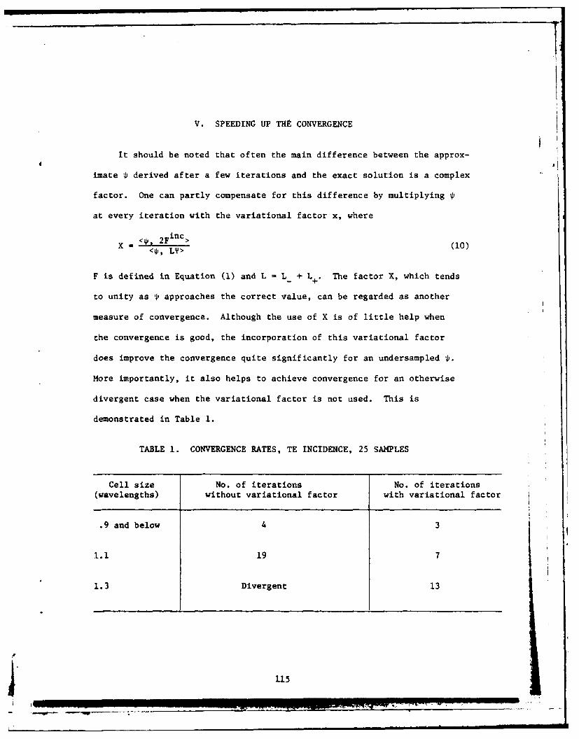
V. SPEEDING UP THE CONVERGENCE
It should be noted that often the main difference between the approx-
imate 1Pi derived after a few iterations and the exact solution is a complex
factor. One can partly compensate for this difference by multiplying 0p
at every iteration with the variational factor x, where
,incX 2F >(10)
<0i, LT>
F is defined in Equation (1) and L - L_ + L +. The factor X, which tends
to unity as approaches the correct value, can be regarded as another
measure of convergence. Although the use of X is of little help when
the convergence is good, the incorporation of this variational factor
does improve the convergence quite significantly for an undersampled4.
More importantly, it also helps to achieve convergence for an otherwise
divergent case when the variational factor is not used. This is
demonstrated in Table 1.
TABLE 1. CONVERGENCE RATES, TE INCIDENCE, 25 SAMPLES
Cell size No. of iterations No. of iterations(wavelengths) without variational factor with variational factor
.9 and below 4 3
1.1 19 7
1.3 Divergent 13
115
VI. RESULTS
A corrugated-surface twist polarizer was constructed and experimentally
tested. Its duty ratio b/a was 0.5, with a -21 mm, or 0.6A at the center
frequency of 8.5 GHz, and d - 7.62 mm or 0.216X. A comparison between the
computed and measured axial ratios at various frequencies is presented in
Fig. 4 for an incidence angle of 5* Agreement between computations and
measurements appears to be very good, despite an uncertainty of about
t10 in the measurement setup and a slight inclination of the plane of
incidence relative to the direction of periodicity. Interestingly,
when the frequency is increased beyond the grating-lobe bound of about
dNz1 (not shown in Fig. 4), the computation predicts a sudden change
in the axial ratio and the reflection coefficient, whose magnitude is
no longer equal to one. The loss of reflected energy i.n the fundamental
space harmonic is obviously accounted for by a second space harmonic,
or a grating lobe.
A 116

ACKNOILEDGERENT
The authors are thankful to their colleague Ross Lampe for providing
the experimental data for the twist reflector that were used to compare
to the theoretical results der ed in this paper.
117
!F

REFERENCES
1. 0. B. Kesler, W. F. Montgomery and C. C. Liu, "A millimeter-wave
scanning antenna for radar application," Proc. 1979 Antenna Applications
Symposium, Robert Allerton Park, Monticello, IL.
2. E. 0. Houseman, Jr., "A millimeter wave polarization twist antenna,"
Proc. IEEE 1978 AP-S Int'l. Symposium, Washington, D.C., pp. 51-53.
3. D. K. Waineo and J. F. Konieczny, "Millimeter wave monopulse antenna
with rapid scan capability," Proc. IEEE 1979 AP-S Int'l. Symposium,
Seattle, WA, pp. 477-480.
4. W. B. Offutt, L. K. DeSize and W. H. Yale, "Methods of Obtaining
Circular Polarization," Sec. 17.7, Antenna Engineering Handbook,
(J. Jasik, (Ed.)). New York: McGraw-Hill, 1961.
5. W. L. Ko and R. Mittra, "A new approach based on a combination of
integral equation and asymptotic techniques for solving electromagnetic
scattering problems," IEEE Trans. Antennas Propagat., Vol. AP-25, No. 2,
pp. 187-197, March 1977.
6. R. Mittra and A. Tsao, "Solving a class of open and closed dis-
continuity problems without matrix inversion," Proc. 1980 URSI
Symposium, Quebec, Canada, p. 89.
7. R. Mittra and A. Tsao, "A spectral-iteration approach for analyzing
scattering from frequency selective surfaces," to be published.
8. J. D. Hanfling, G. Jerinic and L. R. Lewis, "Twisterflector design
using E-type and H-type modes:' to be published in AP-S Transactions.
A 118

6 TWISTPOLARIZER
E
FEED
REFLECTOR
Figure 1. Twist Reflector Antenna system
119
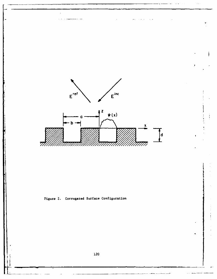
ref inc
jz
IdI
Figure 2. Corrugated Surface Configuration
120
IfN-

Pas -h
Figure 3. A Unit Cell of Corrugated Surface
121

60 . , . '
000 •COMPUTED
50• o e•a MEASURED
4000
40
40 0
00 6
30-
0 *
0I 0 •00
x 0
0 30 00
20 ••• 10
0048.0 ,00 , I , 0 0
08.5 9.0 9.5
FREQUENCY (GHz)
Figure 4. Twist Polarizer Performance
0122