electrostatic control unit - lemmer
TRANSCRIPT

VM 5000
B_03269
II 3 G
c us
Electrostatic control unitfor electrostatic hand spray guns
Translation of the original
Operating manual
Edition 03/2012
(in submission)


3
VM 5000
OPERATING MANUAL
EDITION 03/2012 PART NUMBER DOC 2318718
Contents
1 ABOUT THESE INSTRUCTIONS 51.1 Languages 51.2 Warnings, notes and symbols in these instructions 5
2 GENERAL SAFETY INSTRUCTIONS 62.1 Safety instructions for the operator 62.1.1 Electrical equipment 62.1.2 Personnel qualifi cations 62.1.3 A safe work environment 62.2 Safety instructions for staff 72.2.1 Safe handling of WAGNER spray units 72.2.2 Earth the unit 72.2.3 Material hoses 72.2.4 Cleaning 82.2.5 Handling hazardous liquids, varnishes and paints 82.2.6 Touching hot surfaces 82.3 Correct use 92.4 Safety-relevant information about discharges 92.5 Use in an explosion hazard area 102.5.1 Correct use 102.5.2 Explosion protection according to CE 102.5.3 Explosion protection according to FM 112.6 German regulations and guidelines 11
3 GUARANTEE AND CONFORMITY DECLARATIONS 123.1 Important notes on product liability 123.2 Guarantee claim 123.3 CE-Conformity 13
4 DESCRIPTION 144.1 Fields of application, using in accordance with the instructions 144.2 Scope of delivery 144.3 Technical data 154.4 Functional description 164.5 Operating elements and connections 164.5.1 Operating elements front side 164.5.2 Connections on the rear side 18
5 PREPARATION BEFORE STARTING WORK 195.1 Additional components 195.2 Positioning of the unit 205.3 Earthing 205.4 Example for AirCoat spraying system 225.5 Device confi guration 245.5.1 Overview of parameters 245.5.2 Access to the device confi guration mode 255.5.3 Setting example „Parameter C11“ 265.6 Operating hours counter/warning display 285.6.1 Set up and query service counter 295.7 External signal 30

4
VM 5000
OPERATING MANUAL
EDITION 03/2012 PART NUMBER DOC 2318718
Contents
6 START-UP AND OPERATION 326.1 Start-up the control unit 326.2 Set and save recipes 336.2.1 Setting the high-voltage 346.2.2 Setting the current limiting 356.2.3 Spray display 366.3 Standby mode 376.4 „Conduct service“ display 38
7 TROUBLE SHOOTING AND SOLUTION 39
8 MAINTENANCE AND REPAIR 418.1 Maintenance 418.2 Repair 41
9 PRODUCT DISPOSAL 41
10 ACCESSORIES 42
11 SPARE PARTS 4311.1 How to order spare parts? 4311.2 VM 5000 spare parts list 44

5
VM 5000
OPERATING MANUAL
EDITION 03/2012 PART NUMBER DOC 2318718
1.2 WARNINGS, NOTES AND SYMBOLS IN THESE INSTRUCTIONS
1.1 LANGUAGES
1 ABOUT THESE INSTRUCTIONS
Warning instructions in this manual point out particular dangers to users and equipment and state measures for avoiding the hazard. These warning instructions fall into the following categories:
Danger - imminent danger. Non-observance will result in death, serious injury and serious material damage.
Warning - possible danger. Non-observance can result in death, serious injury and serious material damage.
Caution - a possibly hazardous situation. Non-observance can result in minor injury.
Note - provide information on particular characteristics and how to proceed.
Caution - a possibly hazardous situation. Non-observance can cause material damage.
SIHI_0100_GB
DANGERThis line warns of the hazard! Possible consequences of failing to observe the warning instructions.The signal word points out the hazard level.
The measures for preventing the hazard and its consequences.
SIHI_0103_GB
WARNING This line warns of the hazard! Possible consequences of failing to observe the warning instructions.The signal word points out the hazard level.
The measures for preventing the hazard and its consequences.
SIHI_0101_GB
C AUTION This line warns of the hazard! Possible consequences of failing to observe the warning instructions.The signal word points out the hazard level.
The measures for preventing the hazard and its consequences.
SIHI_0102_GB CAUTION This line warns of the hazard! Possible consequences of failing to observe the warning instructions . The signal word points out the hazard level.
The measures for preventing the hazard and its consequences.
2310484 2318718 2318719 --- 2318720 2318721

6
VM 5000
OPERATING MANUAL
EDITION 03/2012 PART NUMBER DOC 2318718
2 GENERAL SAFETY INSTRUCTIONS
2.1 SAFETY INSTRUCTIONS FOR THE OPERATOR
2.1.1 ELECTRICAL EQUIPMENT
2.1.2 PERSONNEL QUALIFICATIONS
2.1.3 A SAFE WORK ENVIRONMENT
Keep these operating instructions to hand near the unit at all times. Always follow local regulations concerning occupational safety and accident prevention.
Electrical plant and unit To be provided in accordance with the local safety requirements with regard to the operating mode and ambient influences. May only be maintained by skilled electricians or under their supervision. Must be operated in accordance with the safety regulations and electrotechnicalregulations.Must be repaired immediately in the event of problems. Must be put out of operation if they pose a hazard. Must be de-energized before work is commenced on active parts. Inform staff about planned work, observe electrical safety regulations.
Make sure that the floor in the area where you are working is anti-static in accordance with EN 61340-4-1 (the resistance value may not exceed 100 MOhm).
Ensure that all persons within the working area wear antistatic shoes. Footwear must comply with EN 20344. The measured insulation resistance may not exceed 100 MOhm.
Ensure that during spraying, persons wear anti-static gloves so that they are earthed via the handle of the spray gun.
If protective clothing is worn, including gloves, it has to comply with EN 1149-5. The measured insulation resistance may not exceed 100 MOhm.
Paint mist extraction systems must be fitted on site according to the local regulations. Ensure that the following components of a safe working environment are available:
– Material/air hoses adapted to the working pressure. – Personal safety equipment (breathing and skin protection).
Ensure that there are no ignition sources such as naked flame, glowing wires or hot surfaces in the vicinity. Do not smoke.
Control units Place the control unit outside the spray booth/zone. Place the control unit, if possible, outside the explosion zone (positioning in explosion
zone 2 is enables). Protect the control unit from extreme temperature and moisture changes. Protect the control unit against dirt. Lay and fix the connecting cable correctly. Guarantee that local mains voltage and tension of the equipment agree.
7
VM 5000
OPERATING MANUAL
EDITION 03/2012 PART NUMBER DOC 2318718
2.2.1 SAFE HANDLING OF WAGNER SPRAY UNITS
2.2.2 EARTH THE UNIT
2.2.3 MATERIAL HOSES
2.2 SAFETY INSTRUCTIONS FOR STAFF
Always follow the information in these instructions, particularly the general safety instructions and the warning instructions.Always follow local regulations concerning occupational safety and accident prevention.
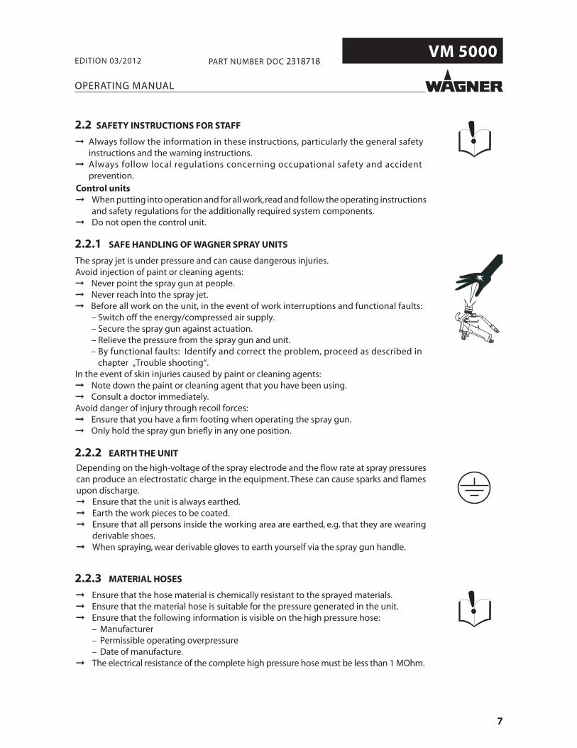
The spray jet is under pressure and can cause dangerous injuries. Avoid injection of paint or cleaning agents:
Never point the spray gun at people. Never reach into the spray jet. Before all work on the unit, in the event of work interruptions and functional faults:
– Switch off the energy/compressed air supply. – Secure the spray gun against actuation. – Relieve the pressure from the spray gun and unit.
– By functional faults: Identify and correct the problem, proceed as described in chapter „Trouble shooting“.
In the event of skin injuries caused by paint or cleaning agents: Note down the paint or cleaning agent that you have been using. Consult a doctor immediately.
Avoid danger of injury through recoil forces: Ensure that you have a firm footing when operating the spray gun. Only hold the spray gun briefly in any one position.
Depending on the high-voltage of the spray electrode and the flow rate at spray pressures can produce an electrostatic charge in the equipment. These can cause sparks and flames upon discharge.
Ensure that the unit is always earthed. Earth the work pieces to be coated. Ensure that all persons inside the working area are earthed, e.g. that they are wearing
derivable shoes. When spraying, wear derivable gloves to earth yourself via the spray gun handle.
Ensure that the hose material is chemically resistant to the sprayed materials. Ensure that the material hose is suitable for the pressure generated in the unit. Ensure that the following information is visible on the high pressure hose:
– Manufacturer – Permissible operating overpressure – Date of manufacture.
The electrical resistance of the complete high pressure hose must be less than 1 MOhm.

8
VM 5000
OPERATING MANUAL
EDITION 03/2012 PART NUMBER DOC 2318718
2.2.4 CLEANING
2.2.5 HANDLING HAZARDOUS LIQUIDS, VARNISHES AND PAINTS
2.2.6 TOUCHING HOT SURFACES
When preparing or working with paint and when cleaning the unit, follow the workinginstructions of the manufacturer of the paints, solvents and cleaning agents being used. Take the specified protective measures, in particular wear safety goggles, protective clothing and gloves, as well as hand protection cream if necessary. Use a mask or breathing apparatus if necessary. For sufficient health and environmental safety: Operate the unit in a spray booth or on a spraying wall with the ventilation (extraction) switched on. Wear suitable protective clothing when working with hot materials.
➞ Touch hot surfaces only if you are wearing protective gloves. ➞ When operating the unit with a coating material with a temperature of > 43 °C; 109.4 °F: - Identify the unit with a warning label that says „Warning - hot surface“. Order No. 9998910 Information label9998911 Safety label
De-energize the unit electrically.Disconnect the pneumatic supply line.Relieve the pressure from the unit.Ensure that the flash point of the cleaning agent is at least 15K above the ambient tem-perature. Otherwise, the cleaning works shall be carried out at forced ventilated clea-ning place.To clean, use only solvent-soaked cloths and brushes. The cleaning process mustn´t damage parts of the spray gun, it mustn´t be an abrasive procedure.Parts of spray gun mustn´t submerged or soaked into solvent.Non-ignitable cleaning liquids shall be preferred.A suitable solvent for cleaning the spray gun depends on the part of the gun and on the material that needs to be removed. It´s recommended to use only non-polar solvents to prevent a conductive residue on critical components. If it´s necessary to use polar solvents to clean the spray gun components, all residue must be removed by using a nonconductive non-polar solvent.
All electrical components cannot be cleaned or soaked in any solvents.An explosive gas/air mixture forms in closed containers.
When cleaning units with solvents, never spray into a closed container.For cleaning liquids only electrically leading containers may be used.The containers must be earthed.

9
VM 5000
OPERATING MANUAL
EDITION 03/2012 PART NUMBER DOC 2318718
Cleaning of the control unitIf there are deposits on the surfaces, the unit may form electrostatic charges. Flames or sparks can form if there is a discharge.
Remove deposits from the surfaces to maintain conductivity. Use only a damp cloth to clean the unit.
Surface spraying of the control unit Do not spray unit parts with electrostatic (e.g. electrostatic spray gun).
2.4 SAFETY-RELEVANT INFORMATION ABOUT DISCHARGES
The plastic parts of the spray gun are charged electrostatically by the high-voltage field of the spray pistol. Harmless discharges (brush discharges) are possible after contact with plastic parts. They are completely harmless for people. The corona discharge at the electrode end is visible during darkness at a distance of bebetween 4 and 10 mm; 0.15 and 0.4 inches, between the spray gun and spray object.
2.3 CORRECT USE

10
VM 5000
OPERATING MANUAL
EDITION 03/2012 PART NUMBER DOC 2318718
2.5 USE IN AN EXPLOSION HAZARD AREA
2.5.1 CORRECT USE
The VM 5000 control unit may only be used in combination with the GM 5000EA orGM 5000EAC hand spray guns. If the control unit is operated in combination with devicesother than the above-mentioned spray guns, the SIRA and FM authorizations (typeapprovals) cease to apply. These electrostatic hand spray guns are suitable for spraying liquid materials, in particular coating materials that follow AirCoat or Airspray techniques. Coating materials that contain solvents from the II A explosion group may be used.
The control unit is designed together with the spray gun in accordance with the 94/9/EC (ATEX 95) directive. The spray gun is suitable for use in potentially explosive areas zone 1 and the control unit in the area of zone 2.
Authorization (type approval) by SIRA for zone 1 (spray gun)
0102 II (2) G
SIRA 11 ATEX 5374X
CE Communautés Européennes
0102 Notifi ed inspection body: PTB
Ex Symbol for explosion protection
II Unit class II
(2) Category 2 (Zone 1) applies only to spray gun
G Ex-atmosphere gas
SIRA 11 ATEX 5374X Number of type approval certifi cate
Authorization for zone 2 (control unit)
II 3 G Ex nR IIA T4 Gc
CE Communautés Européennes
Ex Symbol for explosion protection
II Unit class II
3 Category 3 (Zone 2)
G Ex-atmosphere gas
Ex nR Ignite protection class „Restricted breathing“
IIA Equipment group IIA
T4 Temperature class T4
Gc Equipment protection type Gc
2.5.2 EXPLOSION PROTECTION ACCORDING TO CE

11
VM 5000
C US
OPERATING MANUAL
EDITION 03/2012 PART NUMBER DOC 2318718
2.5.3 EXPLOSION PROTECTION ACCORDING TO FM
For Electrostatic Finishing Applicationsusing Class I, Group D, Spray Material
In accordance with 2316160
This device has been manufactured and tested according to the FM (Factory Mutual)standard „Class Number 7260“ (Approval Standard for Electrostatic Finishing Equipment) by FM. All tested combinations of devices including accessories are given in the FM Control Document with part number 2316160.
(the device is in submission)
2.6 GERMAN REGULATIONS AND GUIDELINES
a) BGV A3 Electrical units and equipmentb) BGR 500 Part 2, Chap. 2.36 Working with liquid ejection devicesc) BGR 500 Part 2, Chap. 2.29 Using coating materialsd) BGR 104 Explosion protection rulese) TRBS 2153 Avoiding ignition risksf ) BGR 180 Setting up for cleaning with solvents for cleaning workpieces with
solventsg) ZH 1/406 Guidelines for liquid ejection devicesh) BGI 740 Painting rooms and equipmentj) BGI 764 Electrostatic coatingj) Betr.Sich.V. Plant Safety Ordinance
Note: All titles can be ordered from Heymanns Publishing House in Cologne, or they are to be found in the Internet.
Authorization (type approval) by FM for class 1, div. 1 (spray gun)
The „Gas-proof“ type of explosion protection is only guaranteed if all sealed elements in the control unit are available and undamaged. During operation, all electric connections in the control unit and relevant plug connectors or shut-off devices have to be tightly sealed.
12
VM 5000
OPERATING MANUAL
EDITION 03/2012 PART NUMBER DOC 2318718
3 GUARANTEE AND CONFORMITY DECLARATIONS
3.1 IMPORTANT NOTES ON PRODUCT LIABILITY
3.2 GUARANTEE CLAIM
As a result of an EC regulation, effective as from January 1, 1990, the manufacturer shall only be liable for his product if all parts come from him or are approved by him, and if the devices are properly fitted , operated and maintained. If other makes of accessory and spare parts are used, the manufacturer‘s liability could be fully or partially null and void. The usage of original WAGNER accessories and spare parts guarantees that all safetyregulations are observed.
Full guarantee is provided for this device:We will at our discretion repair or replace free of charge all parts which within 24 months in single-shift, 12 months in 2-shift or 6 months in 3-shift operation from date of receipt by the Purchaser are found to be wholly or substantially unusable due to causes prior to the sale, in particular faulty design, defective materials or poor workmanship.The type of guarantee provided is such that the device or individual components of the device are either replaced or repaired as we think fit. The resulting costs, in particularshipping charges, road tolls, labour and material costs will be borne by us except where these costs are increased due to the subsequent shipment of the unit to a location other than the address of the purchaser.
We do not provide guarantee for damage that has been caused or contributed to for the following reasons: Unsuitable or improper use, faulty installation or commissioning by the purchaser or a third party, normal wear, negligent handling, defective maintenance, unsuitable coating products, substitute materials and the action of chemical, electro chemical or electrical agents, except when the damage is attributable to us. Abrasive coating products such as red lead, emulsions, glazes, liquid abrasives, zinc dust paints and similar reduce the service life of valves, packings, spray guns, tips, cylinders, pistons etc. Signs of wear and tear due to such causes are not covered by this guarantee.
Components that have not been manufactured by WAGNER are subject to the original guarantee of the manufacturer.Replacement of a component does not extend the period of guarantee of the device.The unit should be inspected immediately upon receipt. To avoid losing the guarantee, we or the supplier company are to be informed in writing about obvious faults within 14 days upon receipt of the device.
We reserve the right to have the guarantee compliance met by a contracting company.The services provided by this guarantee depend on evidence being provided in the form of an invoice or delivery note. If an examination discovers that no guarantee claim exists, the costs of repairs are charged to the purchaser.
It is clearly stipulated that this guarantee claim does not represent any constraint to statutoryregulations or regulations agreed contractually in our general terms and conditions.
J. Wagner AG
13
VM 5000
OPERATING MANUAL
EDITION 03/2012 PART NUMBER DOC 2318718
3.3 CE-CONFORMITY
CE Certificate of ConformityThe certificate is enclosed with this product. The certificate of conformity can be reordered from your WAGNER representative, quoting the product and serial number.
Part number : 2310487
EC declaration of conformity as defi ned by Atex-directive 94/9/EC.Herewith we declare that the supplied version of:
Electrostatic hand spraying system
VM 500 VM 5000 GM 5000EA GM5000EAC
Complies with the following guidelines:
94/9/EG 2004/108/EG 2002/96/EG
2006/42/EG 2002/95/EG
Applied standards, in particular:
DIN EN 50050:2007 DIN EN 61000-6-2:2006 DIN EN ISO 12100:2011
DIN EN 1953:2010 DIN EN 61000-6-4:2011 DIN EN 60079-0: 2010
DIN EN 60079-15: 2011 DIN EN 60204-1: 2007
Applied national technical standards and specifi cations, in particular:
BGI 764
EC type approval certifi cate:
SIRA 11 ATEX 5374X issued by SIRA Certifi cation,CH4 9JN, Chester, England, notifi ed body no. 0518
Identifi cation:
Control unit: 0102
II (2) G SIRA 11 ATEX 5374X
II 3 G Ex nR IIA T4 Gc
Spray gun: 0102
II 2 G EEx 0.24mJ SIRA 11 ATEX 5374X

14
VM 5000
OPERATING MANUAL
EDITION 03/2012 PART NUMBER DOC 2318718
4 DESCRIPTION
4.1 FIELDS OF APPLICATION, USING IN ACCORDANCE WITH THE INSTRUCTIONS
WAGNER‘s electrostatic control unit VM 5000 controls the high voltage supply to the spray guns used to apply liquid coating media GM 5000EAC and GM 5000EA.The VM 5000 may only be operated together with the above-mentioned hand spray guns.If the control unit is operated in combination with devices other than the above-mentioned spray guns, the SIRA and FM authorizations (type approvals) cease to apply.As a result of the „Gas-proof“ type of explosion protection, the control unit is suitable for use in ex-zone 2. This is guaranteed providing all sealed elements in the control unit are available and undamaged. During operation, all electric connections in the control unit and relevant plug connectors or shut-off devices have to be tightly sealed.
4.2 SCOPE OF DELIVERY
Quantity Part No. Description
1 2310477 VM 5000 control unit
The standard equipment includes:
Quantity Part No. Description
1 241270 Mains cable with Stak200; 3 m; 9.8 ft
1 130215 Earthing cable 10 m; 32.8 ft
2 9951117 Delay-action fuses 1.0 AT
1 2310487 ES 5000 manual Declaration of conformity
1 2310484 VM 5000 Operating manual German
1 see 1.1 Operating manual in the local language
The delivery note shows the exact scope of delivery.

15
VM 5000
AB
C
B_03270
EXT
100
80
60
40
20
μA
80
60
40
20
10
kVR3
R1
R2
VM 5000
OPERATING MANUAL
EDITION 03/2012 PART NUMBER DOC 2318718
4.3 TECHNICAL DATA
Input voltage 115 VAC - 230 VAC, 50 Hz / 60 Hz
Input power max. 40 W
Input current max. 0.5 A
Output voltage max. 20 Vpp
Output current max. 1.0 A AC
High-voltage limit 80 kV DC
Spraying current limit 100 μA DC
Polarity for negative high-voltage generator
Protection class IP 54 *
Weight (without cables) 2.3 kg; 5.07 lb
Working temperature range 0-40 °C; 32-104 °F
* Splash-proof protection is only guaranteed when the gun cable socket is screwed to the device plug and the mains cable plug is fi xed to the control unit plug with the safety clip.
Measurements:
VM 5000
mm inches
A 250 9.84
B 180 7.09
C 120 4.72
16
VM 5000
OPERATING MANUAL
EDITION 03/2012 PART NUMBER DOC 2318718
1 Push button: Recipe 1
2 Push button: Recipe 2
3 Push button: Recipe 3
4 Luminous display: R1 Lights up if recipe 1 is used.
5 Luminous display: R2 Lights up if recipe 2 is used.
6 Luminous display: R3 Lights up if recipe 3 is used.
7 Declaration of values for high-voltage in kV
8 Illuminated display: High-voltage● Lights up green.● Display range: 0-80 kV.● Single display: Preset value of high-voltage.● Bar display: Set voltage.
9 Illuminated display: Spraying current● Lights up green.● Display range: 0-100 μA.● Single display: Spraying current limit.● Bar display: Actual spraying current.
10 Declaration of values for spray voltage in μA
4.4 FUNCTIONAL DESCRIPTION
The VM 5000 control unit together with the suitable GM 5000EA or GM 5000EAC spray gun and other components form an electro-static hand spray system. The VM 5000 supplies the control voltage for the spray gun, in which high-voltage is subsequently produced. The tar-geted high-voltage and the current limiting in the spray gun is adjusted at the control unit and can be saved in three different recipes. The high-voltage supply is switched on and off with the trigger of the spray gun.The special linear characteristic for high-voltage ensures that if the spray gun is brought too close to the work piece (or to earth) the high-voltage is reduced automatically toprevent an accidental spark discharge.In addition, the VM 5000 control unit has a wide range of other functions, such as anoperating hours counter, service interval display, external approval, fault display and an easy-to-use interface.
4.5 OPERATING ELEMENTS AND CONNECTIONS
4.5.1 OPERATING ELEMENTS FRONT SIDE
17
VM 5000
EXT
100
80
60
40
20
μA
80
60
40
20
10
kVR3
R1
R2
VM 5000
B_03271
1
2
3
4
5
16
21
6
7
192022 1718
138 9 12 141110 15
OPERATING MANUAL
EDITION 03/2012 PART NUMBER DOC 2318718
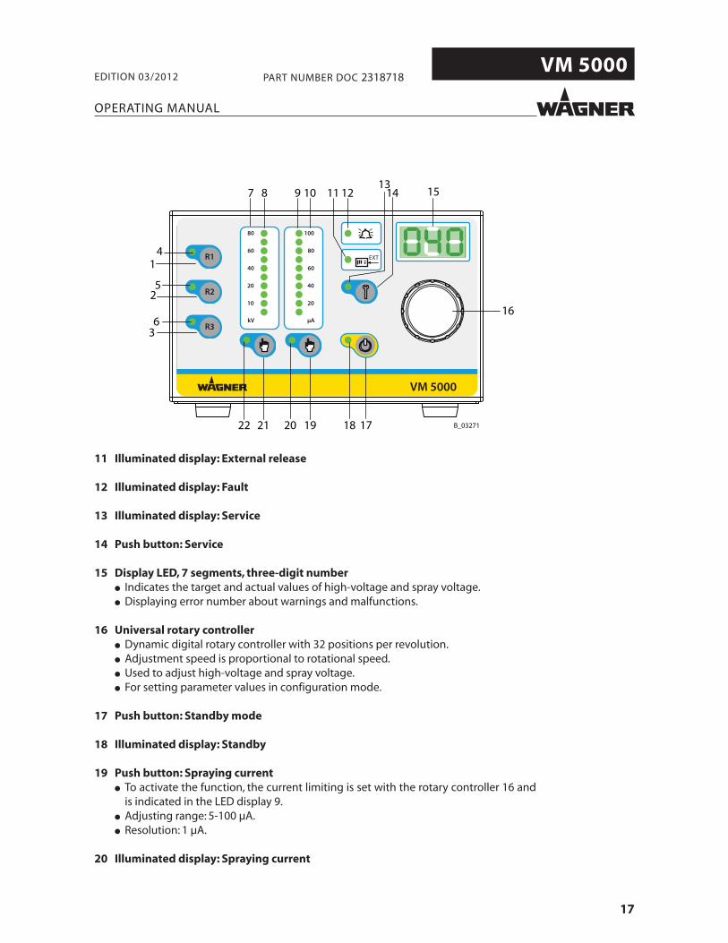
11 Illuminated display: External release
12 Illuminated display: Fault
13 Illuminated display: Service
14 Push button: Service
15 Display LED, 7 segments, three-digit number● Indicates the target and actual values of high-voltage and spray voltage.● Displaying error number about warnings and malfunctions.
16 Universal rotary controller● Dynamic digital rotary controller with 32 positions per revolution.
● Adjustment speed is proportional to rotational speed.● Used to adjust high-voltage and spray voltage.● For setting parameter values in configuration mode.
17 Push button: Standby mode
18 Illuminated display: Standby
19 Push button: Spraying current● To activate the function, the current limiting is set with the rotary controller 16 and is indicated in the LED display 9.● Adjusting range: 5-100 μA.
● Resolution: 1 μA.
20 Illuminated display: Spraying current
18
VM 5000
Typ / Type: VM 5000
115VAC - 230VAC50Hz / 60Hz
2307317
max. 40W
J. WAGNER AGIndustriestrasse 22
CH - 9450 AltstättenMade in Switzerland
Serie Nr.:Serial No.:Spannung:Voltage:
Artikel Nr.:Article No.:
Eingangsleistung:Input Power:
Schutzklasse:Protection Class:Norm:Standard: EN 50050
IP 54
Spannung:Voltage:Strom:Current:
max. 20Vpp
max. 1,0A
Eingangsstrom:Input Current: max. 0.5A
I
0
Main Switch
Nic
ht u
nter
Spa
nnun
g tre
nnen
!
Do
not d
isco
nnec
t und
er v
olta
ge!
Prim.1.0 AT
0102 II (2) G
SIRA 11 ATEX 5374X
II 3 G
Ex nR IIA T4 Gc
B_03272
23
24
25
26 27
29
28
30
OPERATING MANUAL
EDITION 03/2012 PART NUMBER DOC 2318718
23 Mains power input Connection for mains cable with securing clip.
Warning - Do not disconnect under voltage.
24 Primary fuse 1.0 Ampere slow-acting.
25 Mains switch0 = The control unit is deactivated.
I = The control unit is activated.
26 Gun connection To connect a GM 5000EA or GM 5000EAC gun.
Warning - Do not disconnect under voltage.
27 InterfaceWarning - Do not disconnect under voltage.
28 Cover of the interface connections
29 Cover of the service connectionsFor Wagner service personnel only!
30 Knurled nut earthing Earthing cable connection to the system earth.
4.5.2 CONNECTIONS ON THE REAR SIDE
21 Push button: High-voltage● To activate the function, the high-voltage is set with the rotary controller 16 and is indicated in the LED display 8.● Adjusting range: 5-80 kV.
● Resolution: 1 kV.
22 Illuminated display: High-voltage
19
VM 5000
Typ / Type: VM 5000
115VAC - 230VAC50Hz / 60Hz
2307317
max. 40W
J. WAGNER AGIndustriestrasse 22
CH - 9450 AltstättenMade in Switzerland
Serie Nr.:Serial No.:Spannung:Voltage:
Artikel Nr.:Article No.:
Eingangsleistung:Input Power:
Schutzklasse:Protection Class:Norm:Standard: EN 50050
IP 54
Spannung:Voltage:Strom:Current:
max. 20Vpp
max. 1,0A
Eingangsstrom:Input Current: max. 0.5A
I
0
Main Switch
Nic
ht u
nter
Spa
nnun
g tre
nnen
!
Do
not d
isco
nnec
t und
er v
olta
ge!
Prim.1.0 AT
0102 II (2) G
SIRA 11 ATEX 5374X
II 3 G
Ex nR IIA T4 Gb
B_03273
1
2
3
4
5
Typ / Type: VM 5000
115VAC - 230VAC50Hz / 60Hz
2307317
max. 40W
J. WAGNER AGIndustriestrasse 22
CH - 9450 AltstättenMade in Switzerland
Serie Nr.:Serial No.:Spannung:Voltage:
Artikel Nr.:Article No.:
Eingangsleistung:Input Power:
Schutzklasse:Protection Class:Norm:Standard: EN 50050
IP 54
Spannung:Voltage:Strom:Current:
max. 20Vpp
max. 1,0A
Eingangsstrom:Input Current: max. 0.5A
I
0
Main Switch
Nic
ht u
nter
Spa
nnun
g tre
nnen
!
Do
not d
isco
nnec
t und
er v
olta
ge!
Prim.1.0 AT
0102 II (2) G
SIRA 11 ATEX 5374X
II 3 G
Ex nR IIA T4 Gb
B_03287
1
2
3
4
5
OPERATING MANUAL
EDITION 03/2012 PART NUMBER DOC 2318718
5 PREPARATION BEFORE STARTING WORK
5.1 ADDITIONAL COMPONENTS
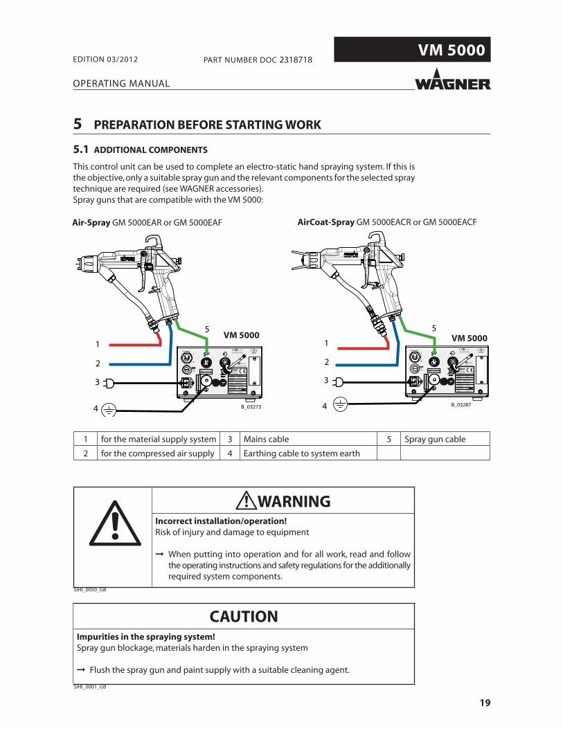
This control unit can be used to complete an electro-static hand spraying system. If this is the objective, only a suitable spray gun and the relevant components for the selected spray technique are required (see WAGNER accessories).Spray guns that are compatible with the VM 5000:
WARNING Incorrect installation/operation! Risk of injury and damage to equipment
When putting into operation and for all work, read and follow the operating instructions and safety regulations for the additionallyrequired system components.
SIHI_0050_GB
CAUTION Impurities in the spraying system! Spray gun blockage, materials harden in the spraying system
Flush the spray gun and paint supply with a suitable cleaning agent.
SIHI_0001_GB
Air-Spray GM 5000EAR or GM 5000EAF AirCoat-Spray GM 5000EACR or GM 5000EACF
VM 5000 VM 5000
1 for the material supply system 3 Mains cable 5 Spray gun cable
2 for the compressed air supply 4 Earthing cable to system earth
20
VM 5000
OPERATING MANUAL
EDITION 03/2012 PART NUMBER DOC 2318718
5.3 EARTHING
Perfect earthing of all system components (work pieces, conveyor, paint supply system, control unit, spray booth or spraying stand, see illustration) is a prerequisite for optimum coating effi ciency and safety.
WARNING Discharge of electrostatically charged components in atmospherescontaining solvents!Explosion hazard from electrostatic sparks or flames
Earth all unit components. Earth the workpieces being painted.
SIHI_0027_GB
5.2 POSITIONING OF THE UNIT
SIHI_0143_GB
DANGERIncorrect installation of the unit!Risk of explosion and equipment damage
Place the unit outside the spray booth/zone.Place the unit, if possible, outside the explosion zone (Positioning in explosion zone 2 is enables).Protect the unit from extreme temperature and moisture changes.Protect the unit against dirt.Lay and fix the connecting cable correctly.
All sealed elements in the control device must be available and undamaged. Duringoperation, all electric connections in the control unit and relevant plug connectors orshut-off devices have to be tightly sealed. When under voltage, neither plug connectors nor any shut-off devices may be separated or opened.
SIHI_0144_GB
WARNINGSparking by separation and joining of live construction units!Danger of explosion by electrical sparks
Fuse holders under tension do not open.Disconnect connectors not under tension.
Remove the service plug cover not under tension.

21
VM 5000
B_03234
R max < 1 MΩ
OPERATING MANUAL
EDITION 03/2012 PART NUMBER DOC 2318718
Earthing schema (example)Conveyor
Control unit
Earthingcable
Spraying stand
Work piece
Materialsupply
Paintcontainer
The imperfect earthing of a work piece will result in:
• Very poor wrap-around.
• Uneven coating thickness.
• Back spraying to the spray gun (contamination) and coater.
The prerequisites for perfect earthing and coating are:
• Clean work piece suspension.
• Earthing of spray booth, conveyor system and suspension on the building side in accordance with the operating instruction or the manufacturer‘s information.
• Earthing of all conductive parts within the working area.
• The earthing resistance of the work piece may not exceed 1 M (Mega Ohm). Note: Resistance to earth measured with 500 V or 1000 V.
• Connect the control unit to the mains system earth.
Floor, derivable
Note for the sprayerThe work shoes and if used the gloves must bederivable.
WARNING Heavy paint mist if earthing is insufficient! Risk of poisoningInsufficient paint application quality
Earth all unit components. Earth the workpieces being painted.
SIHI_0003_GB
Minimum cable cross-section
Control unit 4 mm² (AWG 12)
Material supply 4 mm² (AWG 12)
Paint container 4 mm² (AWG 12)
Conveyor 16 mm² (AWG 6)
Booth 16 mm² (AWG 6)
Spraying stand 16 mm² (AWG 6)

22
VM 5000
7
6
8
45
9
17
1
21615
14
21
12
11
10
B_03158
18 19
20
EXT
100
80
60
40
20
μA
80
60
40
20
10
kV
R3
R1
R2
VM 5000
3
3
13
OPERATING MANUAL
EDITION 03/2012 PART NUMBER DOC 2318718
5.4 EXAMPLE FOR AIRCOAT SPRAYING SYSTEM
Item Description
1 GM 5000EACF spray gun
2 Gun cable
3 Earthing cable
4 Pneumatic pump
5 Carriage
6 Pressure regulator +air fi lter
7 Material suction system
Item Description
8 Return hose
9 High pressure fi lter
10 Compressed air connection
11 Stop valve
12 Air pressure regulator
13 VM 5000 control unit
14 Protective hose
Item Description
15 Air hose
16 Material hose
17 Return valve
18 Container for return fl ow
19 Paint container
20 Container, cleaning agent
21 Mains cable

23
VM 5000
OPERATING MANUAL
EDITION 03/2012 PART NUMBER DOC 2318718
The following points should be noted before commissioning:
➞ Lay earthing cable from the earthing screw on the device to the signal ground and ensure that all other conductive parts within the area of work are earthed.
➞ Connect the VM 5000 electrostatic control unit via the mains cable to the socket interlocked with the extraction system.
➞ Connect the gun cable to the connector socket and screw into place.
➞ Connect the gun to the adjustable, clean air supply.Compressed air quality class 3.5.2 according to ISO 8573.1.
➞ Connect the GM 5000EA or GM 5000EAC to the paint supply as described in the relevant operating manual.
➞ Check that all material-conveying connections are correctly connected.
➞ Check that all air supply connections are connected properly.
➞ Visually check the permissible pressures for all the system components.
➞ Check the level of the separating agent in the pump and add more in necessary.
➞ Prepare a material container, a container for the cleaning agent and an empty container for the return fl ow.
➞ The interface on the back of the control unit has to be protected by the cover.
➞ Connect the system to the air supply.
➞ When starting the unit for the fi rst time -> Clean the system in accordance with the operating manuals for the other components.
24
VM 5000
OPERATING MANUAL
EDITION 03/2012 PART NUMBER DOC 2318718
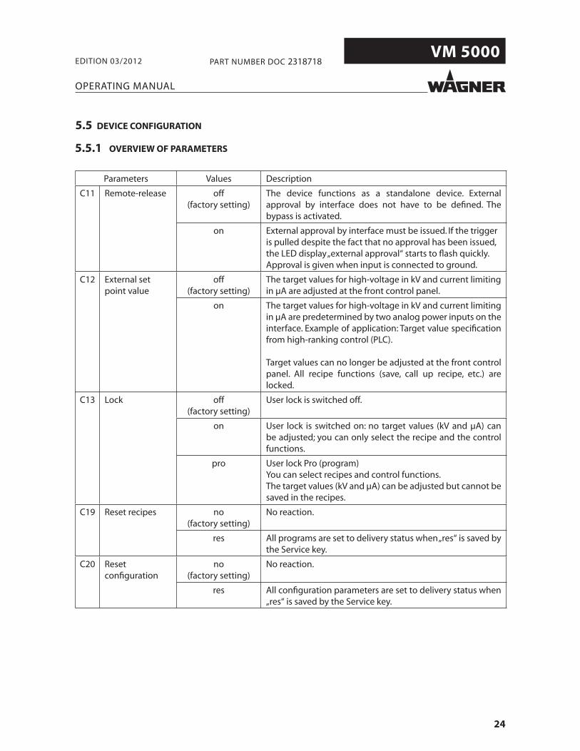
5.5.1 OVERVIEW OF PARAMETERS
Parameters Values Description
C11 Remote-release off(factory setting)
The device functions as a standalone device. External approval by interface does not have to be defi ned. The bypass is activated.
on External approval by interface must be issued. If the trigger is pulled despite the fact that no approval has been issued, the LED display „external approval“ starts to fl ash quickly.Approval is given when input is connected to ground.
C12 External set point value
off(factory setting)
The target values for high-voltage in kV and current limiting in μA are adjusted at the front control panel.
on The target values for high-voltage in kV and current limiting in μA are predetermined by two analog power inputs on the interface. Example of application: Target value specifi cation from high-ranking control (PLC).
Target values can no longer be adjusted at the front control panel. All recipe functions (save, call up recipe, etc.) are locked.
C13 Lock off(factory setting)
User lock is switched off.
on User lock is switched on: no target values (kV and μA) can be adjusted; you can only select the recipe and the control functions.
pro User lock Pro (program)You can select recipes and control functions.The target values (kV and μA) can be adjusted but cannot be saved in the recipes.
C19 Reset recipes no(factory setting)
No reaction.
res All programs are set to delivery status when „res“ is saved by the Service key.
C20 Reset confi guration
no(factory setting)
No reaction.
res All confi guration parameters are set to delivery status when „res“ is saved by the Service key.
5.5 DEVICE CONFIGURATION

25
VM 5000
EXT
100
80
60
40
20
μA
80
60
40
20
10
kVR3
R1
R2
VM 5000
B_03682
EXT
100
80
60
40
20
μA
80
60
40
20
10
kVR3
R1
R2
VM 5000
B_03682
EXT
100
80
60
40
20
μA
80
60
40
20
10
kVR3
R1
R2
VM 5000
B_03682
_01
1718
_02
16
1514
_03
4
15
182022
OPERATING MANUAL
EDITION 03/2012 PART NUMBER DOC 2318718
Works procedure:
1. Switch to „Standby“ bypressing the „Standby“ key (17). The orange LED „Standby“ (18) lights up.
2. Press push button „Service“ (14) and hold it down.
3. Turn the universal control dial (16) with the other hand until the display (15) shows the number „10“. Then release button„Service“ (14). The scrolling text „Confi guration“ is displayed.The device is now inconfi guration mode.
4. The LED display (15) now shows the fi rst confi guration setting C11. At the same time,the two LED displays„High-voltage“ (22) and „Spraying current limit“ (20) will fl ash.
„Standby“ indicator (18)fl ashes quickly.
5.5.2 ACCESS TO THE DEVICE CONFIGURATION MODE

26
VM 5000
EXT
100
80
60
40
20
μA
80
60
40
20
10
kVR3
R1
R2
VM 5000
B_03682
EXT
100
80
60
40
20
μA
80
60
40
20
10
kVR3
R1
R2
VM 5000
B_03682_04
1
2
3
15
182022
_05
15
1921
OPERATING MANUAL
EDITION 03/2012 PART NUMBER DOC 2318718
For ease of operation the confi guration settings are divided into three groups. The fi rst group is for the end user, the other both groups, protected by a password, are reserved for Wagner Service and the Wagner production sites or the Wagner Service Center, which have the necessary infrastructure.
Group (1) illuminated display:Parameters C11 to C20(for the end user)
Group (2):Parameters C21 to C30 (for Wagner service)
Group (3):Parameters C31 to C40 (for production plant; service center)
5.5.3 SETTING EXAMPLE „PARAMETER C11“
After getting started in confi guration mode, the display (15) shows the parameter „C11“ by default.Press one of the Push keys (21) or (19) to select all kinds of parameters for the end user. To change a selected parameter value (e.g. C11), press Push key (14). The content of C11 is displayed (15).
27
VM 5000
EXT
100
80
60
40
20
μA
80
60
40
20
10
kVR3
R1
R2
VM 5000
B_03682
EXT
100
80
60
40
20
μA
80
60
40
20
10
kVR3
R1
R2
VM 5000
B_03682
_06
151413
19 1821 2022
16
_07
17
OPERATING MANUAL
EDITION 03/2012 PART NUMBER DOC 2318718
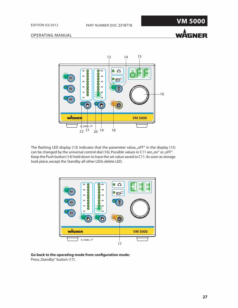
The fl ashing LED display (13) indicates that the parameter value, „oFF“ in the display (15) can be changed by the universal control dial (16). Possible values in C11 are „on“ or „oFF“.Keep the Push button (14) held down to have the set value saved to C11. As soon as storage took place, except the Standby all other LEDs delete LED.
Go back to the operating mode from confi guration mode:Press „Standby“ button (17).

28
VM 5000
EXT
100
80
60
40
20
μA
80
60
40
20
10
kVR3
R1
R2
VM 5000
B_03682_08
151413
4
1
OPERATING MANUAL
EDITION 03/2012 PART NUMBER DOC 2318718
5.6 OPERATING HOURS COUNTER/WARNING DISPLAY
2 hour counters are integrated into the control unit. The absolute counter measures the ongoing hours of operation of the spray gun and with the service hours counter, service intervals can be determined and monitored for the spray gun.
From the standby setting on the control unit you access the screen for the service menu via the push button (14).
Service menu structure (LED display (13) is activated).
Push button Description of display
R1 Display of absolute accrued operating hours of the spray gun.Display format:Counter status < 999 hours: 001 = 1 hour; 291 = 291 hoursCounter status > 1000 hours: 1.23 = 1230 hours; 45.2 = 45200 hours.Maximum display value = 99.9 = 99900 hoursAfterwards it shows fl ashing lines.
R2 Display of temporary service counter and how to reset this counter.
R3 Set service interval in hours or lock this function.

29
VM 5000
EXT
100
80
60
40
20
μA
80
60
40
20
10
kVR3
R1
R2
VM 5000
B_03682
EXT
100
80
60
40
20
μA
80
60
40
20
10
kVR3
R1
R2
VM 5000
B_03682
_09
15
19
1413
6 16
3
_10
15
19
1413
5
162
OPERATING MANUAL
EDITION 03/2012 PART NUMBER DOC 2318718
5.6.1 SET UP AND QUERY SERVICE COUNTER
When using the device for the fi rst time, the function for the service interval counter is deactivated. This function can be activated via the R3 push button (3). The service interval limit can be set within a range of 0 to 999 hours.
Set and save the service interval limit in hours.
Works procedure:
1. Actuate the push button (3) for a short time. Illuminated display (6) lights up.
2. Use the dial (16) to set the service interval limit you want(e.g. 90 hours).
3. Check setting on display (15).4. The value is saved by pressing and
keeping the push button (19) held down together with push button R3 (3) until the display shown (15) starts fl ashing.
Review counter status since last service carried out on gun.
Works procedure:
1. Actuate the push button (2) for a short time. Illuminated display (5) lights up.
2. Read display (15). In the example 46 hours have passed since the last spray gun service. The bar graph on the left indicates that 50% of the set interval time has passed.
3. By pressing and keeping the push button (19) held down, you can reset the display (15) to 0 (reset upon expiry of set interval limit).
30
VM 5000
1
2 3
4
1
2 3
4
1
2
3
4
56
7
8
B 03415
OPERATING MANUAL
EDITION 03/2012 PART NUMBER DOC 2318718
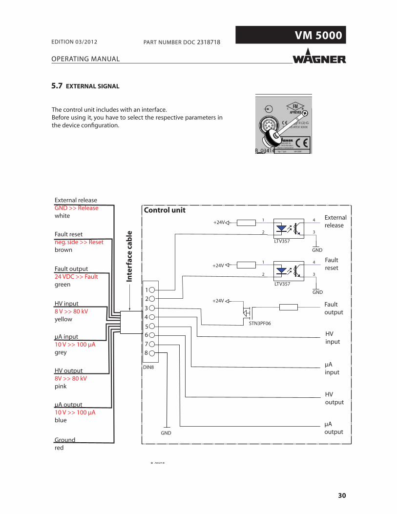
5.7 EXTERNAL SIGNAL
The control unit includes with an interface.Before using it, you have to select the respective parameters in the device confi guration.
External releaseGND >> Releasewhite
Fault resetneg. side >> Resetbrown
Fault output24 VDC >> Faultgreen
HV input8 V >> 80 kVyellow
μA input10 V >> 100 μAgrey
HV output8V >> 80 kVpink
μA output10 V >> 100 μAblue
Groundred
Control unit
Inte
rfac
e ca
ble
External release
Faultreset
Faultoutput
HVinput
μAinput
HVoutput
μAoutput
+24V
+24V
+24V
DIN8
STN3PF06
LTV357
LTV357
GND
GND
GND

31
VM 5000
OPERATING MANUAL
EDITION 03/2012 PART NUMBER DOC 2318718
Pin no. Designation Description
1in
External release Potential-free contact between pin 1 and pin 8 (ground)- closed Approval issued- open Approval not issued
2in
Fault reset Potential-free contact (button) between pin 2 and pin 8 (ground)- If there is a fault, it can be acknowledged by pressing a button.- Acknowledgement is only given via the negative side.
3out
Fault output If there is a fault, +24 VDC is issued at pin 3 in reference to pin 8 (ground).- Maximum current 0.5 A
4in
DC kV in Set point value for high-voltageAnalog d.c. current input between pin 4 in reference to pin 8 (ground)- 0.1 V corresponds to 1 kV- 8.0 V is a maximum specifi cation and corresponds to 80 kV
5in
DC μA in Set point value for spraying current limitAnalog d.c. current input between pin 5 in reference to pin 8 (ground)- 0.1 V corresponds to 1 μA- 10.0 V is a maximum specifi cation and corresponds to 100 μA
6out
DC kV out Output of current actual voltageAnalog d.c. current output between pin 6 in reference to pin 8 (ground)- 0.1 V corresponds to 1 kV- 8.0 V is a maximum specifi cation and corresponds to 80 kV
7out
DC μA out Output of current actual spray currentAnalog d.c. current output between pin 7 in reference to pin 8 (ground)- 0.1 V corresponds to 1 μA- 10.0 V is a maximum specifi cation and corresponds to 100 μA

32
VM 5000
EXT
100
80
60
40
20
μA
80
60
40
20
10
kVR3
R1
R2
VM 5000
B_03682_11
B_03294 B_03295
OPERATING MANUAL
EDITION 03/2012 PART NUMBER DOC 2318718
6 START-UP AND OPERATION
DANGERHigh voltage field! Danger to life from malfunctioning heart pacemakers
Ensure that persons with heart pacemakers: Do not work with the electrostatic spray gun. Remain outside the area of the electrostatic spray gun/work -piece.
SIHI_0049_GB
➞ Observe safety instructions in chapter 2.
6.1 START-UP THE CONTROL UNIT
1. Set toggle switch to position I.
2. All the LEDs -> display test light up for about1 second.
3. The hardware release and version of the software are shown
briefl y in succession in the display.

33
VM 5000
EXT
100
80
60
40
20
μA
80
60
40
20
10
kVR3
R1
R2
VM 5000
B_03682 _12
OPERATING MANUAL
EDITION 03/2012 PART NUMBER DOC 2318718
4. The control unit is ready for use.
Note:Each start process is concluded by allocating the saved target data in the recipe „R1“.
6.2 SET AND SAVE RECIPES
Target values are saved in kV for high-voltage and in μA for spray current limit in therecipe. By standard, the following values are saved ex works in the 3 storage placesavailable for recipes:
Recipe no. Target - high-voltage in kV Target - spray current limit in μA
R1 80 100
R2 60 100
R3 40 80
Recipes 1-3 can be selected and saved directly using program buttons R1, R2 and R3. Once the recipe required has been called up, the individual coating parameters can be called up and changed using the corresponding selection buttons (see chapter 6.2.1 and 6.2.2). When a parameter is changed, the LED on the left of the program button fl ashes to indicate that a parameter value has been changed.
The process for saving parameters is described below.
● To reuse the originally set values, press the program button briefly. The modifi ed values are not taken over.
● To save the modified values, press the appropriate program button and hold for approx. 2 seconds until the LED beside the button flashes quickly. The modified values are then saved.
34
VM 5000
EXT
100
80
60
40
20
μA
80
60
40
20
10
kVR3
R1
R2
VM 5000
B_03682
EXT
100
80
60
40
20
μA
80
60
40
20
10
kVR3
R1
R2
VM 5000
B_03682 _14
8 15
16
_13
22 21
OPERATING MANUAL
EDITION 03/2012 PART NUMBER DOC 2318718
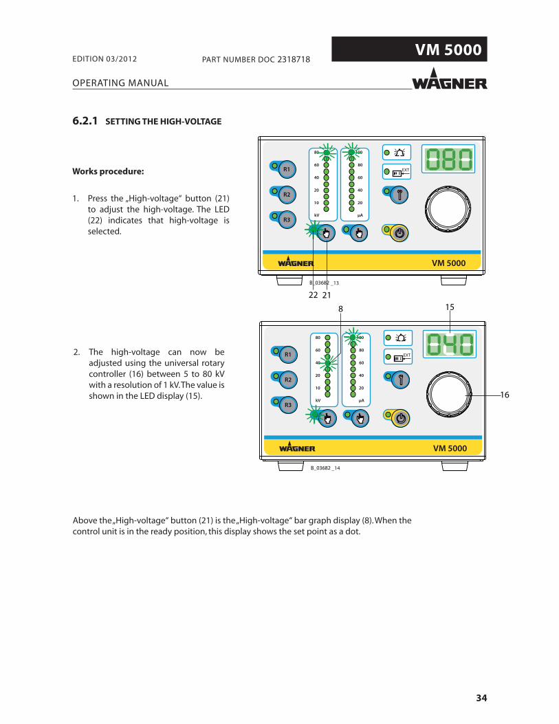
6.2.1 SETTING THE HIGH-VOLTAGE
Above the „High-voltage“ button (21) is the „High-voltage“ bar graph display (8). When the control unit is in the ready position, this display shows the set point as a dot.
Works procedure:
1. Press the „High-voltage“ button (21) to adjust the high-voltage. The LED (22) indicates that high-voltage isselected.
2. The high-voltage can now beadjusted using the universal rotary controller (16) between 5 to 80 kV with a resolution of 1 kV. The value is shown in the LED display (15).
35
VM 5000
EXT
100
80
60
40
20
μA
80
60
40
20
10
kVR3
R1
R2
VM 5000
B_03682
EXT
100
80
60
40
20
μA
80
60
40
20
10
kVR3
R1
R2
VM 5000
B_03682 _16
159
16
_15
15
1920
OPERATING MANUAL
EDITION 03/2012 PART NUMBER DOC 2318718
6.2.2 SETTING THE CURRENT LIMITING
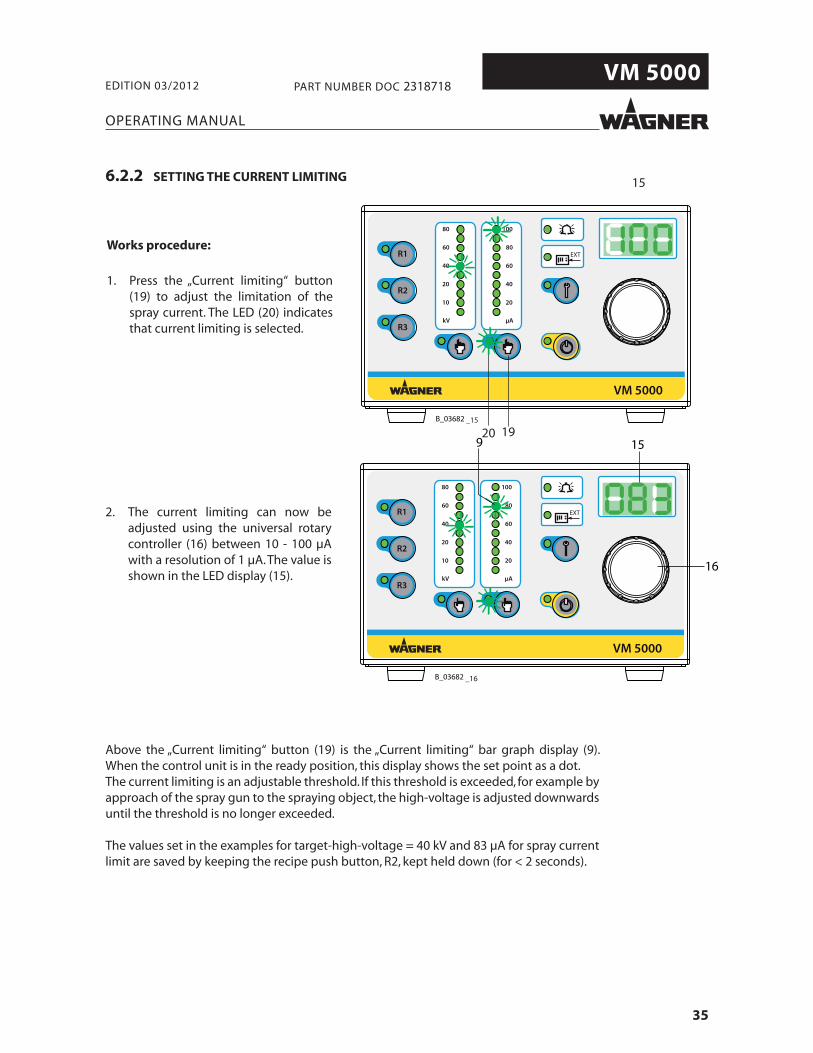
Above the „Current limiting“ button (19) is the „Current limiting“ bar graph display (9). When the control unit is in the ready position, this display shows the set point as a dot.The current limiting is an adjustable threshold. If this threshold is exceeded, for example by approach of the spray gun to the spraying object, the high-voltage is adjusted downwards until the threshold is no longer exceeded.
The values set in the examples for target-high-voltage = 40 kV and 83 μA for spray current limit are saved by keeping the recipe push button, R2, kept held down (for < 2 seconds).
Works procedure:
1. Press the „Current limiting“ button (19) to adjust the limitation of the spray current. The LED (20) indicates that current limiting is selected.
2. The current limiting can now be adjusted using the universal rotary controller (16) between 10 - 100 μA with a resolution of 1 μA. The value is shown in the LED display (15).

36
VM 5000
EXT
100
80
60
40
20
μA
80
60
40
20
10
kVR3
R1
R2
VM 5000
B_03682
EXT
100
80
60
40
20
μA
80
60
40
20
10
kVR3
R1
R2
VM 5000
B_03682
_17
_18
OPERATING MANUAL
EDITION 03/2012 PART NUMBER DOC 2318718
6.2.3 SPRAY DISPLAY
Ready to spray using R2 recipe. See picture below.
Control unit is ready.
The LEDs for the target values light up in a dot arrangement and the value for high-voltage is displayed in digits. If you press the push button for current limiting, the set target value for the spray current limit is displayed in digits.
Spray using recipe R2.
High-voltage is created by pressing the trigger on the spray gun. The LEDs light up in a bar and display the actual values. The current actual value for the activated push button for high-voltage (kV) is displayed in digits. If the push button for the spray current limit is pressed, the respective LED lights up and the respective actual value appears in μA.

37
VM 5000
EXT
100
80
60
40
20
μA
80
60
40
20
10
kVR3
R1
R2
VM 5000
B_03682
EXT
100
80
60
40
20
μA
80
60
40
20
10
kVR3
R1
R2
VM 5000
B_03682
_1918 17
_20
OPERATING MANUAL
EDITION 03/2012 PART NUMBER DOC 2318718
6.3 STANDBY MODE
If you want to spray without high-voltage, select standby mode.Press push button (17) briefl y and the standby (18) LED display lights up. All the other LEDs go out.
From the standby mode (17) you access the previously saved standby mode by pressing the push button (17) again. See fi gure below.
Note:This function can be activated and used from the gun.

38
VM 5000
EXT
100
80
60
40
20
μA
80
60
40
20
10
kVR3
R1
R2
VM 5000
B_03682 _21
13 14
OPERATING MANUAL
EDITION 03/2012 PART NUMBER DOC 2318718
6.4 „CONDUCT SERVICE“ DISPLAY
Prerequisite:The function „Service interval limit“ is activated.
„Conduct service on spray gun“Once the time for the defi ned service interval has expired, the LED display (13) starts to fl ash.The fl ashing service display merely acts as a warning. You can continue working without any limitations.
39
VM 5000
EXT
100
80
60
40
20
μA
80
60
40
20
10
kVR3
R1
R2
VM 5000
B_03271
1
2
3
4
5
16
21
6
7
192022 1718
138 9 12 141110 15
OPERATING MANUAL
EDITION 03/2012 PART NUMBER DOC 2318718
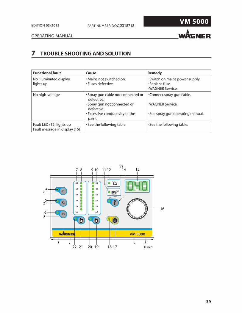
7 TROUBLE SHOOTING AND SOLUTION
Functional fault Cause Remedy
No illuminated displaylights up
• Mains not switched on.• Fuses defective.
• Switch on mains power supply.• Replace fuse.• WAGNER Service.
No high-voltage • Spray gun cable not connected or defective.
• Spray gun not connected or defective.
• Excessive conductivity of the paint.
• Connect spray gun cable.
• WAGNER Service.
• See spray gun operating manual.
Fault LED (12) lights upFault message in display (15)
• See the following table. • See the following table.
40
VM 5000
EXT
100
80
60
40
20
μA
80
60
40
20
10
kVR3
R1
R2
VM 5000
B_03682 _22
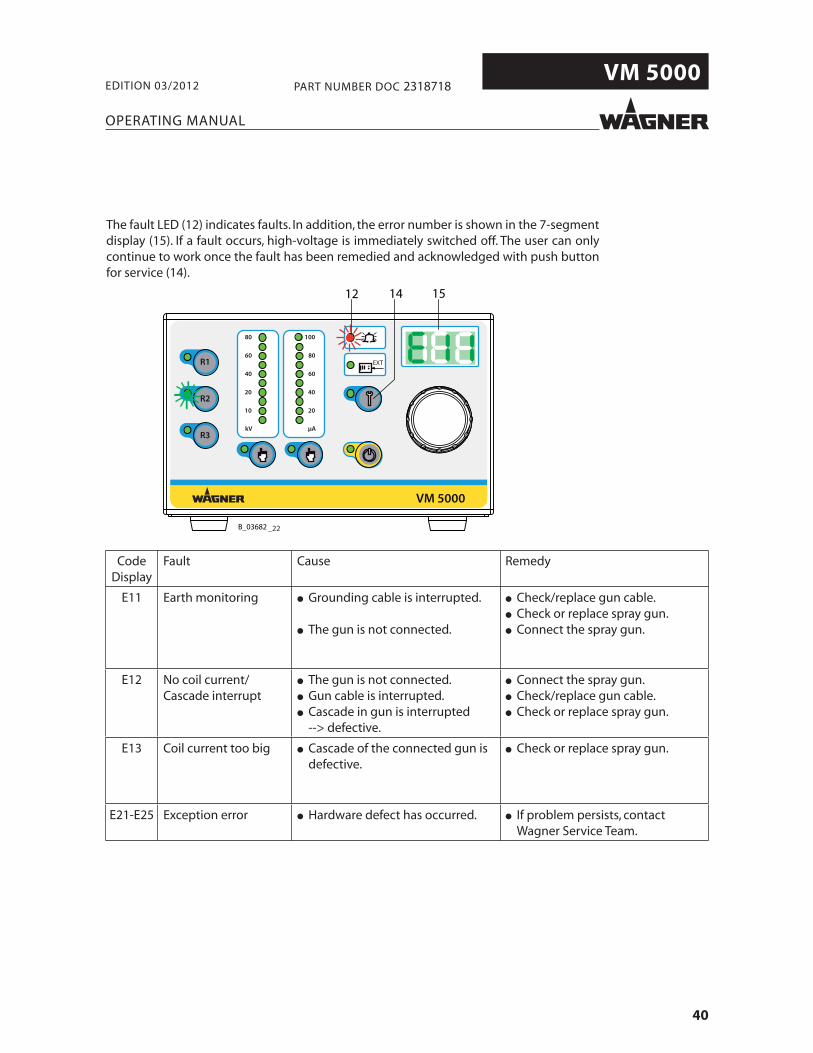
12 14 15
OPERATING MANUAL
EDITION 03/2012 PART NUMBER DOC 2318718
CodeDisplay
Fault Cause Remedy
E11 Earth monitoring ● Grounding cable is interrupted.
● The gun is not connected.
● Check/replace gun cable.● Check or replace spray gun.● Connect the spray gun.
E12 No coil current/Cascade interrupt
● The gun is not connected.● Gun cable is interrupted.● Cascade in gun is interrupted --> defective.
● Connect the spray gun.● Check/replace gun cable.● Check or replace spray gun.
E13 Coil current too big ● Cascade of the connected gun is defective.
● Check or replace spray gun.
E21-E25 Exception error ● Hardware defect has occurred. ● If problem persists, contact Wagner Service Team.
The fault LED (12) indicates faults. In addition, the error number is shown in the 7-segment display (15). If a fault occurs, high-voltage is immediately switched off. The user can only continue to work once the fault has been remedied and acknowledged with push button for service (14).

41
VM 5000
OPERATING MANUAL
EDITION 03/2012 PART NUMBER DOC 2318718
9 PRODUCT DISPOSAL
SIHI_0127_GB
NoteDo not dispose of waste electrical equipment with the house-hold refuse!In accordance with European Directive 2002/96/EC on the disposal of waste electrical equipment and its implementation in national law, this product may not be disposed of with the household refuse, but must rather be recycled in an environmentally correct manner. Your waste Wagner electrical device will be taken back by us or our representatives and disposed of environmentally correctly. Please contact one of our service points or one of our representatives or us directly to this purpose.
8 MAINTENANCE AND REPAIR
8.1 MAINTENANCE
8.2 REPAIR
The functionality and completeness of the control unit have to be checked regularly. All sealed elements in the control unit must be available and undamaged. During operation, all electric connections in the control unit and relevant plug connectors or shut-off devices have to be tightly sealed.
The leak tightness of the unit has to be checked every 3 years at least. The „Gas-proof“ requirements according to DIN EN 60079-15:2011 have to be fulfi lled. This inspection may only be carried out by an authorized person or by trained Wagner Service personnel.The mains input terminal shall serve as the test port in the leak-tightness check.
Repairs to the control unit may only be carried out by trained Wagner Service personnel. This also includes opening the control unit.After a successful repair, the seal tightness of the control unit has to be checked.The „Gas-proof“ requirements according to DIN EN 60079-15:2011 have to be fulfi lled.The mains input terminal shall serve as the test port in the leak-tightness check.
SIHI_0144_GB
WARNINGSparking by separation and joining of live construction units!Danger of explosion by electrical sparks
Fuse holders under tension do not open.Disconnect connectors not under tension.
Remove the service plug cover not under tension.

42
VM 5000
B_03735
OPERATING MANUAL
EDITION 03/2012 PART NUMBER DOC 2318718
10 ACCESSORIES
Part No. Description
241270 Mains cable Europe 3 m; 9.8 ft
241271 Mains cable Switzerland 3 m; 9.8 ft
264626 Mains cable USA 2 m; 6.6 ft
264625 Mains cable Japan 3 m; 9.8 ft
2317600 Interface cable VM 500010 m; 32.8 ft
130215 Earthing cable 10 m; 32.8 ft
264332 Earthing cable assy. 0.75 m; 2.5 ft
2327509 Mounting control unit compl.
Note:Hose sets and spray gun cable -> see operating manuals for spray guns.
43
VM 5000
OPERATING MANUAL
EDITION 03/2012 PART NUMBER DOC 2318718
11 SPARE PARTS
11.1 HOW TO ORDER SPARE PARTS?
Always supply the following information to ensure delivery of the right spare part:
Part Number, description and quantity
The quantity need not be the same as the number given in the „Quantity“ column. This number merely indicates how many of the respective parts are used in each sub assembly.
The following information is also required to ensure smooth processing of your order:
- Address for the invoice- Address for delivery- Name of the person to be contacted in the event of any queries- Type of delivery required (air freight or mail, sea route or overland route, etc.)
Marks in spare parts lists
Note to column „K“ in the following spare parts lists.
= Wearing parts Note: No liability is assumed for wearing parts
= Not part of standard equipment, available, however, as additional extra.
SIHI_0141_GB
WARNING Incorrect maintenance/repair! Risk of injury and damage to the equipment
Repairs and part replacement may only be carried out byspecially trained staff or a WAGNER service center.Before all work on the unit and in the event of work interruptions:- Switch off the energy/compressed air supply.- Relieve the pressure from the spray gun and unit.- Secure the spray gun against actuation.Observe the operating instructions when carrying out all work.

44
VM 5000
Typ / Type:
VM 5000
115VAC - 230VAC
50Hz / 60Hz
2307317
max. 40W
J. WAGNER AG
Industriestrasse 22
CH - 9450 Altstätten
Made in Switzerland
Serie Nr.: Serial No.: Spannung:Voltage:
Artikel Nr.: Article No.:
Eingangsleistung:
Input Power:Schutzklasse:Protection Class:
Norm: Standard:EN 50050
IP 54
max. 20Vpp max. 1,0A
Eingangsstrom:Input Current:
max. 0.5A
I
0
Main Switch
Nicht unter S
pannung trennen!
Do not disconnect under voltage!
Prim. 1.0 AT
0102II (2
) GSIRA 11 ATEX 5374X
II 3 G Ex nR IIC
T4 Gc
B_03286
19
20
2122
23
24
32
26
25
28
29
30
33
3132
27
6
1718
34
161514
13
12
1
11
10
35
78 9
3
2
45
OPERATING MANUAL
EDITION 03/2012 PART NUMBER DOC 2318718
11.2 VM 5000 SPARE PARTS LIST

45
VM 5000
OPERATING MANUAL
EDITION 03/2012 PART NUMBER DOC 2318718
Item Qty Part No. Description
1 1 2310477 VM 5000 control unit
2 1 9903312 Oval head screw, Phillips screwdriver, form H
3 1 9952593 Protection cap Equipment connector
4 1 9950330 Safety catch for connector sockets
5 2 9903306 Oval head screw, Phillips screwdriver, form H
6 1 9910102 Hexagon nut
7 1 9910522 High knurled nut
8 1 9920118 Washer
9 1 9922017 Lock washer outside toothed
10 2 9903311 Oval head screw, Phillips screwdriver, form H
11 1 241323 Cover, white
12 1 2317538 Print compl. VM 5000 control
13 3 263400 Distance bush
14 3 9922011 Lock washer outside toothed
15 3 9910103 Hexagon nut
16 5 2312348 Hexagon lock nut
17 4 9922011 Lock washer outside toothed
18 4 9903312 Oval head screw, phillips screwdriver, form H
19 8 2306405 Countersunk screw, phillips screwdriver, form Z
20 1 2307315 Seal
21 1 2307309 Cover
22 4 9990839 Buffer
23 1 9955176 Power pack
24 5 2309112 Spacer
25 1 2311875 Incremental encoder
26 1 2317539 Print compl. VM 5000 display (with pos. 25)
27 1 2304462 Cover
28 1 2304461 Rotary knob
29 1 9953536 2-pin rocker switch
30 1 9952587 Equipment plug
31 1 9955021 Fuse holder
32 2 9951117 Delay-action fuses 1.0 AT
33 1 9971519 Rubber seal
34 1 9955601 Speedily fuse 2.5 A
35 1 2325264 Seal
46
VM 5000
OPERATING MANUAL
EDITION 03/2012 PART NUMBER DOC 2318718
GermanyJ. WAGNER GmbHOtto-Lilienthal-Str. 18Postfach 1120D- 88677 MarkdorfTelephone: +49 7544 5050Telefax: +49 7544 505200E-Mail: [email protected]
SwitzerlandJ. WAGNER AGIndustriestrasse 22Postfach 663CH- 9450 AltstättenTelephone: +41 (0)71 757 2211Telefax: +41 (0)71 757 2222E-Mail: [email protected]
BelgiumWSB Finishing EquipmentVeilinglaan 56/58B- 1861 WolvertemTelephone: +32 (0)2 269 4675Telefax: +32 (0)2 269 7845E-Mail: [email protected] / HP www.wsb-wagner.eu
DenmarkWAGNER Industrial Solution ScandinaviaViborgvej 100, SkærgærDK- 8600 SilkeborgTelephone: +45 70 200 245Telefax: +45 86 856 027E-Mail [email protected]
United KingdomWAGNER Spraytech (UK) Ltd.Haslemere WayTramway Industrial EstateGB- Banbury, OXON OX16 8TYTelephone: +44 (0)1295 265 353Telefax: +44 (0)1295 269861E-Mail: [email protected]
FranceJ. WAGNER France S.A.R.L.Parc de Gutenberg - Bâtiment F88, Voie la CardonF- 91127 Palaiseau-CedexTelephone: +33 1 825 011 111Telefax: +33 1691 946 55E-Mail: [email protected]
NetherlandsWSB Finishing Equipment B.V.De Heldinnenlaan 200NL- 3543 MB Utrecht
Telephone: +31 (0) 30 241 4155Telefax: +31 (0) 30 241 1787E-Mail: [email protected] / HP www.wsb-wagner.eu
ItalyWAGNER COLORA S.r.lVia Fermi, 3I- 20875 Burago di Molgora (MB)
Telephone: +39 039 625021Telefax: +39 039 6851800E-Mail: [email protected]
JapanWAGNER Spraytech Ltd.2-35, Shinden NishimachiJ- Daito Shi, Osaka, 574-0057
Telephone: +81 (0) 720 874 3561Telefax: +81/ (0) 720 874 3426E-Mail: [email protected]
AustriaJ. WAGNER GmbHOtto-Lilienthal-Str. 18Postfach 1120D- 88677 MarkdorfTelephone: +49 (0) 7544 5050Telefax: +49 (0) 7544 505200E-Mail: [email protected]
SwedenWAGNER Industrial Solutions ScandinaviaSkolgatan 61SE- 568 31 SkillingarydTelephone: +46 (0) 370 798 30Telefax: +46 (0) 370 798 48E-Mail: [email protected]
SpainWAGNER Spraytech Iberica S.A.Ctra. N- 340, Km. 1245,4E- 08750 Molins de Rei (Barcelona)Telephone: +34 (0) 93 680 0028Telefax: +34 (0) 93 668 0156E-Mail: [email protected]
CzechoslovakiaWAGNER s.r.o.Nedasovská Str. 34515521 Praha 5 - ZlicinTelephone: +42 (0) 2 579 50 412Telefax: +42 (0)2 579 51 052E-Mail: [email protected]
USAWAGNER Systems Inc.300 Airport Road, unit 1Elgin, IL 60123 USATelephone: +1 630 503 2400Telefax: +1 630 503 2377E-Mail: [email protected]


CERTIFIE
D
2318718