electrostatic control unit - · pdf fileelectrostatic control unit for electrostatic manual...
TRANSCRIPT
VM 500
c us
B_03416
VM 500
Electrostatic Control Unit
for Electrostatic Manual Spray Guns
Version 07/2014
Translation of the Original
Operating Manual

3
VM 500
OPERATING MANUAL
EDITION 07/2014 ORDER NUMBER DOC2344502
Contents
1 ABOUT THIS OPERATING MANUAL 5
1.1 Preface 51.2 Warnings, Notices, and Symbols in this Operating Manual 51.3 Languages 61.4 Abbreviations in the Text 6
2 CORRECT USE 7
2.1 Device Type 72.2 Type of Use 72.3 Safety Parameters 82.4 Reasonably Foreseeable Misuse 82.5 Residual Risks 8
3 IDENTIFICATION 9
3.1 Explosion Protection According to FM 93.2 Permissible Device Combinations 93.3 Notes to German Regulations and Guidelines 9
4 GENERAL SAFETY INSTRUCTIONS 10
4.1 Safety Instructions for the Operator 104.1.1 Electrical Equipment 104.1.2 Staff Qualifi cations 104.1.3 Safe Work Environment 114.2 Safety Instructions for Staff 114.2.1 Safe Handling of WAGNER Spray Devices 124.2.2 Grounding the Device 124.2.3 Material Hoses 134.2.4 Cleaning 134.2.5 Handling Hazardous Liquids, Lacquers and Paints 144.2.6 Touching Hot Surfaces 144.3 Correct Use 144.4 Safety Information on Discharges 154.5 Protective and Monitoring Equipment 15
5 DESCRIPTION 16
5.1 Areas of Application 165.2 Functional Description 165.3 Technical Data 165.4 Scope of Delivery 175.5 Operating Elements and Connections 185.5.1 Operating Elements Front Side 185.5.2 Connections on the Rear Side 19
6 COMMISSIONING AND OPERATION 20
6.1 Training Assembly/Commissioning Staff 206.2 Storage Conditions 206.3 Installation Conditions 206.4 Additional Components 216.5 Placement of the Device 226.6 Grounding 226.7 Example: AirCoat Spraying System 24
4
VM 500
OPERATING MANUAL
EDITION 07/2014 ORDER NUMBER DOC2344502
Table of Contents
7 OPERATION 26
7.1 Training the Operating Staff 267.2 Safety Instructions 267.3 Start-up and Spraying 277.4 Standby Mode 28
8 TROUBLESHOOTING AND RECTIFICATION 29
9 MAINTENANCE AND REPAIR 30
9.1 Maintenance 309.2 Repair 30
10 PRODUCT DISPOSAL 30
11 ACCESSORIES 31
12 SPARE PARTS 32
12.1 How Can Spare Parts Be Ordered? 3212.2 Spare Parts List VM 500 33
13 WARRANTY 35
13.1 Important Notes Regarding Product Liability 3513.2 Warranty Claim 35
5
VM 500
OPERATING MANUAL
EDITION 07/2014 ORDER NUMBER DOC2344502
1.2 WARNINGS, NOTICES, AND SYMBOLS IN THIS OPERATING MANUAL
1.1 PREFACE
1 ABOUT THIS OPERATING MANUAL
The operating manual contains information about safely operating, maintaining, cleaning and repairing the device.The operating manual is part of the device and must be available to operating and service staff .Operating and service staff should be instructed according to the safety instructions.The device may only be operated in compliance with this operating manual.This equipment can be dangerous if it is not operated according to the instructions in this operating manual.
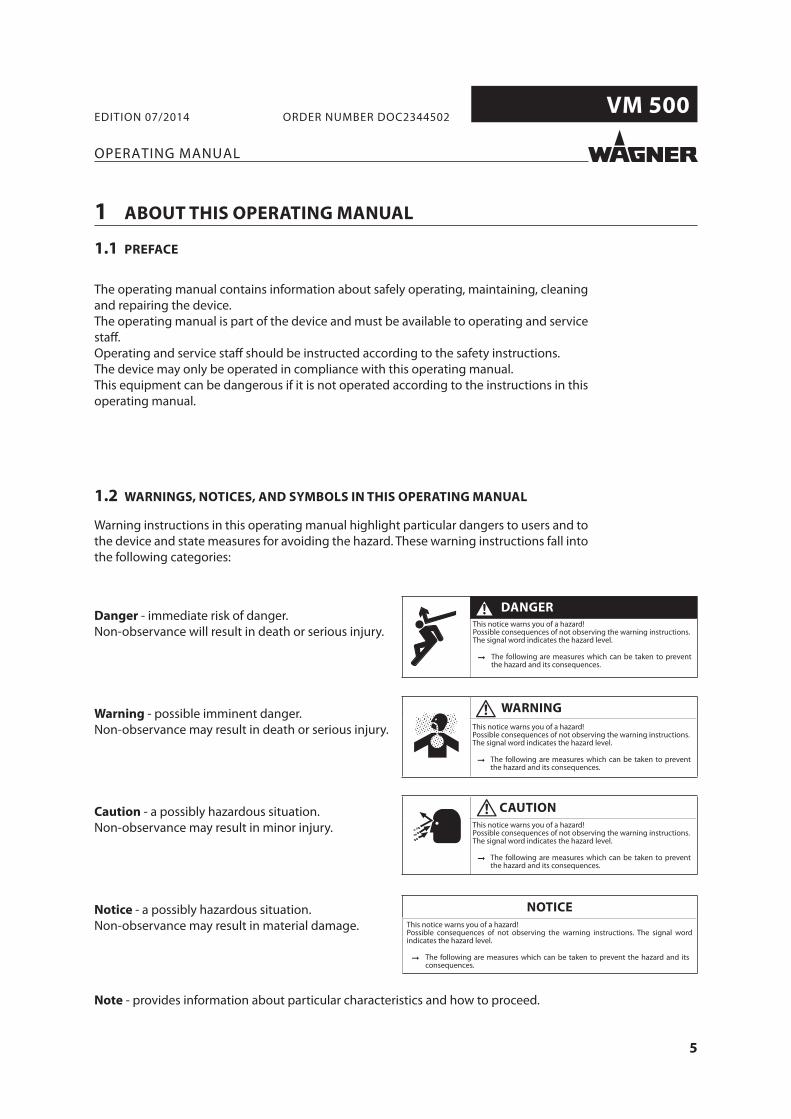
Warning instructions in this operating manual highlight particular dangers to users and to the device and state measures for avoiding the hazard. These warning instructions fall into the following categories:
Danger - immediate risk of danger.Non-observance will result in death or serious injury.
Warning - possible imminent danger.Non-observance may result in death or serious injury.
Caution - a possibly hazardous situation.Non-observance may result in minor injury.
Notice - a possibly hazardous situation.Non-observance may result in material damage.
Note - provides information about particular characteristics and how to proceed.
This notice warns you of a hazard!Possible consequences of not observing the warning instructions.The signal word indicates the hazard level.
The following are measures which can be taken to prevent the hazard and its consequences.
DANGER
This notice warns you of a hazard!Possible consequences of not observing the warning instructions.The signal word indicates the hazard level.
The following are measures which can be taken to prevent the hazard and its consequences.
WARNING
This notice warns you of a hazard!Possible consequences of not observing the warning instructions.The signal word indicates the hazard level.
The following are measures which can be taken to prevent the hazard and its consequences.
CAUTION
This notice warns you of a hazard!Possible consequences of not observing the warning instructions. The signal word indicates the hazard level.
The following are measures which can be taken to prevent the hazard and its consequences.
NOTICE
6
VM 500
OPERATING MANUAL
EDITION 07/2014 ORDER NUMBER DOC2344502
1.3 LANGUAGES
1.4 ABBREVIATIONS IN THE TEXT
Number of piecesPositionMarking in the spare parts lists
Order No. Order numberET Spare part
Stainless steelTwo components
The operating manual is available in the following languages:German English 2344502
7
VM 500
OPERATING MANUAL
EDITION 07/2014 ORDER NUMBER DOC2344502
2.1 DEVICE TYPE
2 CORRECT USE
Control unit for controlling GM 5000EA or GM 5000EAC electrostatic spray guns.
WAGNER‘s electrostatic control unit VM 500 controls the high-voltage supply to the spray guns used to apply liquid coating media GM 5000EAC and GM 5000EA.The VM 500 may only be operated together with the above-mentioned manual spray guns. If the control unit is operated in combination with devices other than the above-mentioned spray guns, the FM authorizations (type approvals) cease to apply.These electrostatic manual spray guns are suitable for spraying liquid products, in particular coating products that follow AirCoat or Airspray techniques. Coating products containing solvents of explosion class II A may be used.
2.2 TYPE OF USE
Incorrect use!
Risk of injury and damage to the device.
Only connect original Wagner spray guns to the VM 500 control unit. Only connect the GM 5000EA or GM 5000EAC spray guns.
WARNING
8
VM 500
OPERATING MANUAL
EDITION 07/2014 ORDER NUMBER DOC2344502
2.3 SAFETY PARAMETERS
The control unit is only suitable for controlling spray guns. J. Wagner AG forbids any other use! The control unit may only be operated under the following conditions:
The operating staff have previously been trained on the basis of this operating manual.The safety regulations listed in this operating manual must be observed.The operating, maintenance, and repair information in this operating manual must be observed.The statutory requirements and accident prevention regulation standards in the country of use must be observed.
The control unit may only be operated if all parameters are set and all measurements / safety checks are carried out correctly.
2.4 REASONABLY FORESEEABLE MISUSE
Coating work pieces which are not groundedUse of defective components, spare parts or accessoriesUse with non-authorized spray guns
2.5 RESIDUAL RISKS
Residual risks are risks which cannot be excluded even in the event of correct use.If necessary, warning and prohibition signs at the relevant points of risk indicate residual risks.
Residual risk Source Consequences Specifi c measures Lifecycle phase
Skin contact with solvent-based paints and cleaning agents
Handling of solvent-based paints and cleaning agents
Skin irritations, Wear protective clothing,
Operation,
allergies observe safety data sheets
maintenance,
disassemblySolvent-based paint in air outside the defi ned working area
Painting outside the defi ned working area
Inhalation of substances hazardous to health
Observe work and operation instructions
Operation,maintenance
9
VM 500
C US
OPERATING MANUAL
EDITION 07/2014 ORDER NUMBER DOC2344502
The following spray guns may be connected to the VM 500 control unit:
GM 5000EA spray gunGM 5000EAC spray gun
Other gun types may only be connected to the control unit after fi rst checking their suitability with Wagner.
3.2 PERMISSIBLE DEVICE COMBINATIONS
3.3 NOTES TO GERMAN REGULATIONS AND GUIDELINES
3.1 EXPLOSION PROTECTION ACCORDING TO FM
This device has been manufactured and tested by FM, according to the FM (Factory Mutual) standard "Class Number 7260" (Approval Standard for Electrostatic Finishing Equipment). All tested combinations of devices including accessories are given in the FM Control Document with part number 2316160.
Authorization (type approval) of FM for class 1, div. 1 (spray gun)
Electrical devices and equipmentPart 2, Chapter 2.36 Working with Liquid Ejection DevicesPart 2, Chapter 2.29 Working with Coating ProductsExplosion protection rulesAvoiding ignition risksEquipment for cleaning work pieces with solventsGuidelines for liquid ejection devicesPainting rooms and equipmentElectrostatic coatingPlant Safety Ordinance
Note: All titles can be ordered from Heymanns Publishing House in Cologne, or they can be found on the Internet.
For Electrostatic Finishing Applications using Class I, Group D, Spray Material
In accordance with 2316160
3 IDENTIFICATION
10
VM 500
OPERATING MANUAL
EDITION 07/2014 ORDER NUMBER DOC2344502
4 GENERAL SAFETY INSTRUCTIONS
4.1 SAFETY INSTRUCTIONS FOR THE OPERATOR
4.1.1 ELECTRICAL EQUIPMENT
4.1.2 STAFF QUALIFICATIONS
Keep this operating manual at hand near the device at all times. Always follow local regulations concerning occupational safety and accident prevention.
Electrical devices and equipment To be provided in accordance with the local safety requirements with regard to the
operating mode and ambient infl uences. May only be maintained by skilled electricians or under their supervision. Must be operated in accordance with the safety regulations and electrotechnical regulations. Must be repaired immediately in the event of problems. Must be decommissioned if they pose a hazard. Must be de-energized before work is commenced on active parts. Inform staff about
planned work. Observe electrical safety regulations.
Control units
Place the control unit outside the spray booth / spray zone. If possible, place the control unit outside the explosion zone (placement in Ex Zone 2 is
permissible). Protect the control unit from extreme temperature and moisture changes. Protect the control unit from contamination. Lay and fi x the connecting cable correctly. Ensure that the local mains voltage and tension of the device match.
Ensure that the device is operated and repaired only by trained persons.
11
VM 500
OPERATING MANUAL
EDITION 07/2014 ORDER NUMBER DOC2344502
4.1.3 SAFE WORK ENVIRONMENT
Ensure that the fl oor in the working area is static dissipative in accordance with EN 61340-4-1 (resistance must not exceed 100 Mohm).
Ensure that all persons within the working area wear static dissipative shoes. Footwear must comply with EN 20344. The measured insulation resistance must not exceed 100 Mohm.
Ensure that during spraying, persons wear static dissipative gloves so that they are grounded via the handle of the spray gun.
If protective clothing is worn, including gloves, it has to comply with EN 1149-5. The measured insulation resistance must not exceed 100 Mohm.
Paint mist extraction systems must be fi tted on site according to local regulations. Ensure that the following components of a safe working environment are available:
– Product/air hoses adapted to the working pressure. – Personal safety equipment (breathing and skin protection).
Ensure that there are no ignition sources such as naked fl ames, sparks, glowing wires, or hot surfaces in the vicinity. Do not smoke.
4.2 SAFETY INSTRUCTIONS FOR STAFF
Always follow the information in this manual, particularly the general safety instructions and the warning instructions.
Always follow local regulations concerning occupational safety and accident prevention.
Control units
When commissioning and for all work, read and follow the operating manual and safety regulations for the additionally required system components.
Do not open the control unit.
12
VM 500
OPERATING MANUAL
EDITION 07/2014 ORDER NUMBER DOC2344502
4.2.1 SAFE HANDLING OF WAGNER SPRAY DEVICES
4.2.2 GROUNDING THE DEVICE
The spray jet is under pressure and can cuse dangerous injuries.Avoid injection of paint or cleaning agents:
Never point the spray gun at people. Never reach into the spray jet. Before all work on the device, in the event of work interruptions and functional faults:
– Switch off the energy/compressed air supply. – Relieve the pressure from the spray gun and device. – Secure the spray gun against actuation. – In the event of functional faults: remedy the fault as described in the "Troubleshooting"
chapter. The liquid ejection devices are to be checked for safe working conditions by an expert
(e.g. Wagner Service Technician) as often as necessary or at least every 12 months, in accordance with the guidelines for liquid emitters (ZH 1/406 and BGR 500 Part 2 Chapter 2.36).
– For shut down devices, the examination can be suspended until the next commissioning. Carry out the work steps as described in the "Pressure Relief/Work Interruptions" chapter:
– if pressure relief is required. – if the spraying work is interrupted or stopped. – before the device is cleaned on the outside, checked, or serviced. – before the spray nozzle is installed or cleaned.In the event of skin injuries caused by paint or cleaning agents:
Note down the paint or cleaning agent that you have been using. Consult a doctor immediately.
Avoid danger of injury through recoil forces: Ensure that you have firm footing when operating the spray gun. Only hold the spray gun briefl y in a position.
Depending on the high-voltage on the spray electrode and the fl ow speed during spraying, an electrostatic charge may occur in the device. This may result in the formation of sparks or fl ames when discharging.
Ensure that the device is grounded at all times. Ground the work pieces to be coated. Ensure that all persons inside the working area are grounded, e.g. that they are wearing
static dissipative shoes. Wear static dissipative gloves for grounding via the spray gun handle when spraying.
13
VM 500
OPERATING MANUAL
EDITION 07/2014 ORDER NUMBER DOC2344502
4.2.3 MATERIAL HOSES
Ensure that the hose material is chemically resistant to the sprayed products. Ensure that the product hose is suitable for the pressure generated in the device. Ensure that the following information can be seen on the high-pressure hose:
– Manufacturer – Permissible operating overpressure – Date of manufacture
Make sure that the hoses are laid only in suitable places. In no case, should hoses be laid in the following places:
– in high-traffic areas, – on sharp edges, – on moving parts, or – on hot surfaces
Make sure that the hoses are never used to pull or move the device. The electrical resistance of the complete high-pressure hose must be less than 1 Mohm.
4.2.4 CLEANING
De-energize the device electrically. Disconnect the pneumatic supply line. Relieve the pressure from the device. Ensure that the fl ash point of the cleaning agent is at least 15 K above the ambient
temperature or that cleaning is undertaken at a cleaning station with technical ventilation. To clean, use cloths and brushes moistened with solvent. Abrasive agents or objects
must not be used. Ensure that the spray gun is not damaged in any way while cleaning. Parts of the spray gun must not be sprayed with or immersed in cleaning agent. Preferably, non-combustible cleaning agents should be used. The choice of the appropriate cleaning agent depends on which parts of the spray gun
have to be cleaned and which product has to be removed. When cleaning the spray gun only use non-polar cleaning agents to prevent conductive residues on the surface of the spray gun. Should it however, be necessary to use a polar cleaning agent, all residues of this cleaning agent have to be removed by using a non-conductive and non-polar cleaning agent, once the cleaning is fi nished.
Ensure that no electrical component is cleaned with nor even immersed into solvent.An explosive gas/air mixture forms in closed tanks.
When cleaning devices with solvents, never spray into a closed tank. Only use electrically conductive tanks for cleaning liquids. The tanks must be grounded.
14
VM 500
OPERATING MANUAL
EDITION 07/2014 ORDER NUMBER DOC2344502
4.2.5 HANDLING HAZARDOUS LIQUIDS, LACQUERS AND PAINTS
When preparing or working with lacquer and when cleaning the device, follow the working instructions of the manufacturer of the lacquers, solvents and cleaning agents being used.
Take the specifi ed protective measures, in particular wear safety goggles, protective clothing and gloves, as well as hand protection cream if necessary.
Use a mask or breathing apparatus if necessary. For suffi cient health and environmental safety: operate the device in a spray booth or
on a spraying wall with the ventilation (extraction) switched on. Wear suitable protective clothing when working with hot products.
4.3 CORRECT USE
4.2.6 TOUCHING HOT SURFACES
Only touch hot surfaces if you are wearing protective gloves. When operating the device with a coating product with a temperature of > 43 °C;
109.4 °F: - Identify the device with a warning label "Warning - hot surface".Order No.
9998910 Instruction label9998911 Protection sticker
WAGNER accepts no liability for any damage arising from incorrect use. Use the device only to work with the products recommended by WAGNER. Only operate the device as a whole. Do not deactivate safety fi xtures. Use only WAGNER original spare parts and accessories.
15
VM 500
OPERATING MANUAL
EDITION 07/2014 ORDER NUMBER DOC2344502
4.4 SAFETY INFORMATION ON DISCHARGES
The plastic parts of the spray gun are charged electrostatically by the high-voltage fi eld of the spray gun. In case of c ontact with plastic parts harmless discharges (brush discharges) may occur. They are completely non-hazardous for human health.When keeping a distance of 4 to 10 mm; 0.15 to 0.4 inch between spray gun and object to be sprayed, the corona discharge at the end of the electrode is visible in the dark.
Surface spraying of the control unit
Never spray device parts using electrostatic equipment (electrostatic spray gun!).
Cleaning the control unit
If there are deposits on the surfaces, the device may form electrostatic charges. Flames or sparks can form during discharge.
Remove deposits from the surfaces to maintain conductivity. Only use a damp cloth to clean the device.
4.5 PROTECTIVE AND MONITORING EQUIPMENT
Protective and monitoring equipment!
Risk of injury and damage to the device.
Protective and monitoring equipment must not be removed, modifi ed or rendered unusable.
Regularly check for perfect functioning. If defects are detected on protective and monitoring equipment,
the system must not be operated until these defects are remedied.
WARNING
16
VM 500
OPERATING MANUAL
EDITION 07/2014 ORDER NUMBER DOC2344502
5 DESCRIPTION
5.1 AREAS OF APPLICATION
Incorrect use!
Risk of injury and damage to the device.
Only connect original Wagner spray guns to the VM 500 control unit. Only connect the GM 5000EA or GM 5000EAC spray guns.
WARNING
The VM 500 control unit, together with the matching GM 5000EA or GM 5000EAC spray gun and other components, form an electrostatic hand spray system. The VM 500 supplies the control voltage for the spray gun, in which high-voltage is subsequently produced. The high-voltage supply is switched on and off with the trigger of the spray gun.The special linear characteristic for high-voltage ensures that if the spray gun is brought too close to the work piece (or to earth) the high-voltage is reduced automatically to prevent an accidental spark discharge.The VM 500 control unit also off ers a fault display.
5.2 FUNCTIONAL DESCRIPTION
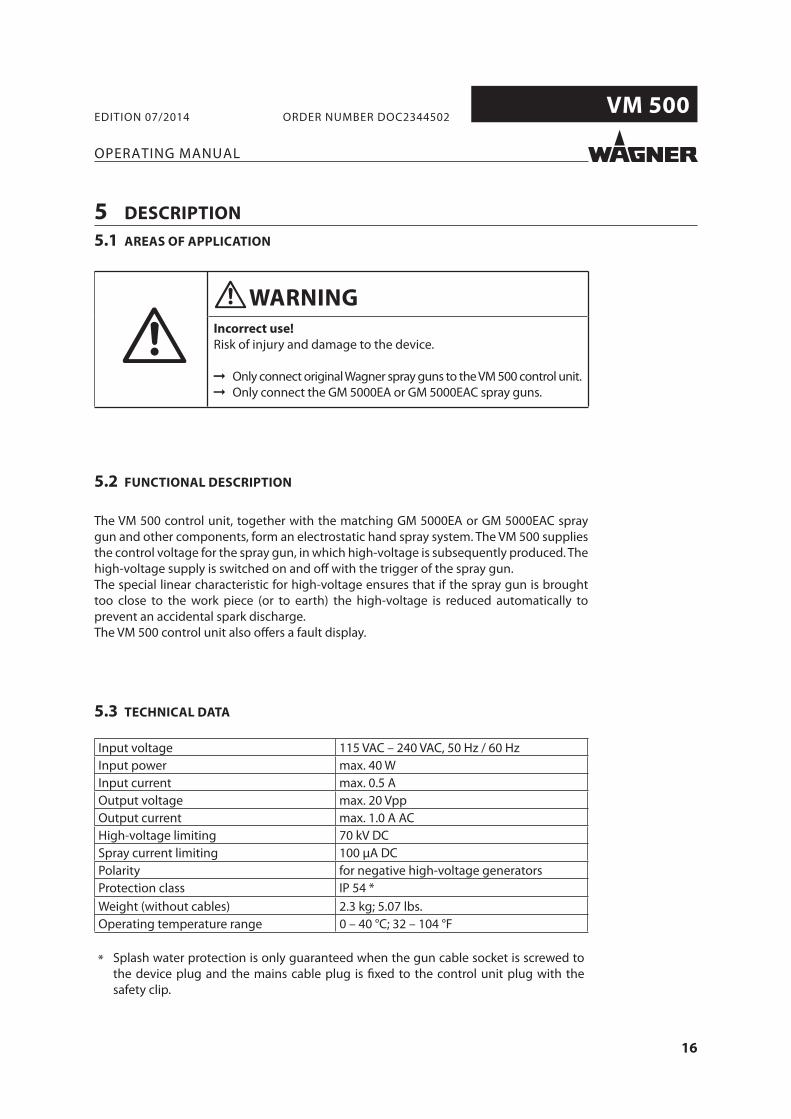
Input voltage 115 VAC – 240 VAC, 50 Hz / 60 HzInput power max. 40 WInput current max. 0.5 AOutput voltage max. 20 VppOutput current max. 1.0 A ACHigh-voltage limiting 70 kV DCSpray current limiting 100 μA DCPolarity for negative high-voltage generatorsProtection class IP 54 *Weight (without cables) 2.3 kg; 5.07 lbs.Operating temperature range 0 – 40 °C; 32 – 104 °F
* Splash water protection is only guaranteed when the gun cable socket is screwed to the device plug and the mains cable plug is fi xed to the control unit plug with the safety clip.
5.3 TECHNICAL DATA
17
VM 500
AB
C
B_03417
VM 500
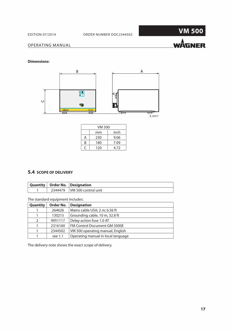
VM 500mm inch
A 230 9.06B 180 7.09C 120 4.72
OPERATING MANUAL
EDITION 07/2014 ORDER NUMBER DOC2344502
Dimensions:
Quantity Order No. Designation
1 2344479 VM 500 control unit
The standard equipment includes:Quantity Order No. Designation
1 264626 Mains cable USA; 2 m; 6.56 ft1 130215 Grounding cable, 10 m, 32.8 ft2 9951117 Delay-action fuse 1.0 AT1 2316160 FM Control Document GM 5000E1 2344502 VM 500 operating manual, English1 see 1.1 Operating manual in local language
The delivery note shows the exact scope of delivery.
5.4 SCOPE OF DELIVERY
18
VM 500
VM 500
B_03418
34
1 2
OPERATING MANUAL
EDITION 07/2014 ORDER NUMBER DOC2344502
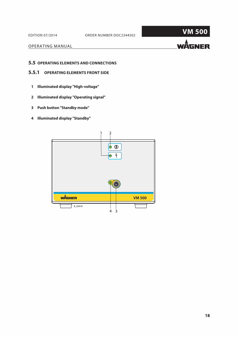
1 Illuminated display "High-voltage"
2 Illuminated display "Operating signal"
3 Push button "Standby mode"
4 Illuminated display "Standby"
5.5 OPERATING ELEMENTS AND CONNECTIONS
5.5.1 OPERATING ELEMENTS FRONT SIDE
19
VM 500
Spannung:Voltage:Strom:Current:
max. 20Vpp
max. 1,0A
Typ / Type: VM 500
115VAC - 240VAC50Hz / 60Hz
2344481
max. 40W
J. WAGNER AGIndustriestrasse 22
CH - 9450 AltstättenMade in Switzerland
Serie Nr.:Serial No.:Spannung:Voltage:
Artikel Nr.:Article No.:
Eingangsleistung:Input Power:Eingangsstrom:Input Current: max. 0.5A
I
0
Main Switch
Prim.1.0 AT
Nic
ht u
nter
Spa
nnun
g tre
nnen
!
Aver
tisse
men
t - N
e pa
s dé
bran
cher
sous
tens
ion!
Do
not d
isco
nnec
t und
er v
olta
ge!
Schutzklasse:Protection Class:
IP 54
B_04169
5
6
7
8
9
10
OPERATING MANUAL
EDITION 07/2014 ORDER NUMBER DOC2344502
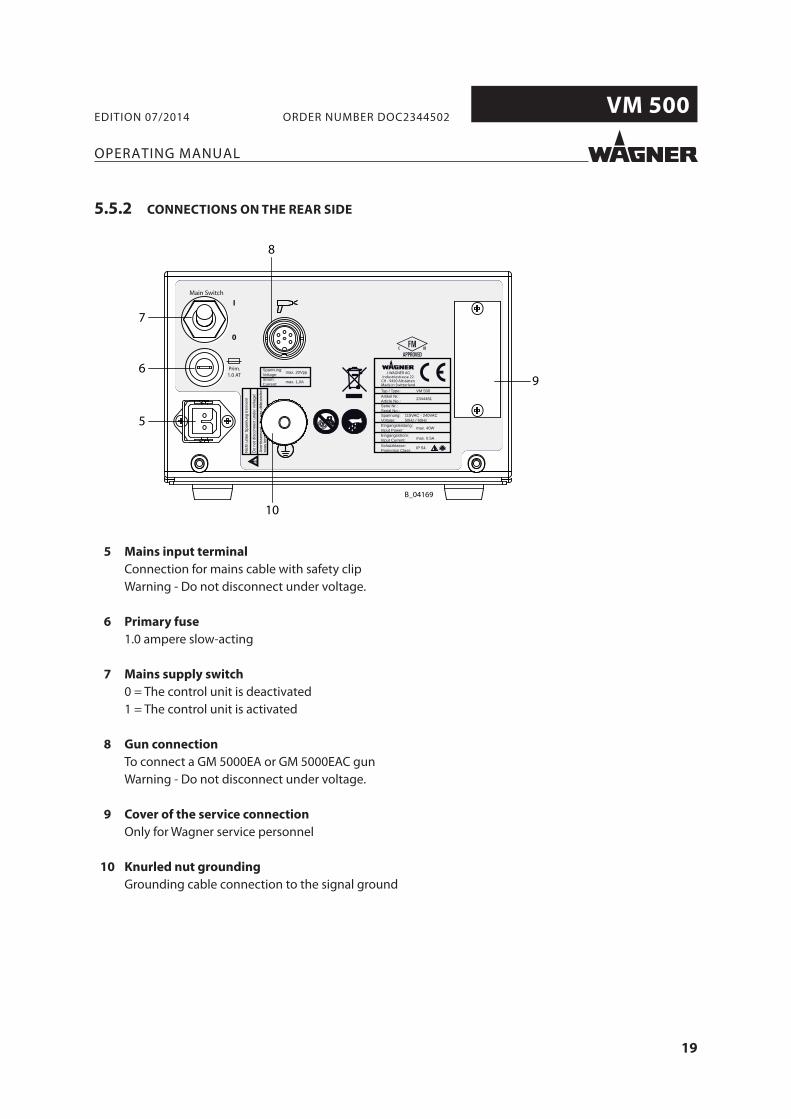
5 Mains input terminal
Connection for mains cable with safety clipWarning - Do not disconnect under voltage.
6 Primary fuse
1.0 ampere slow-acting
7 Mains supply switch
0 = The control unit is deactivated1 = The control unit is activated
8 Gun connection
To connect a GM 5000EA or GM 5000EAC gunWarning - Do not disconnect under voltage.
9 Cover of the service connection
Only for Wagner service personnel
10 Knurled nut grounding
Grounding cable connection to the signal ground
5.5.2 CONNECTIONS ON THE REAR SIDE
20
VM 500
OPERATING MANUAL
EDITION 07/2014 ORDER NUMBER DOC2344502
6 COMMISSIONING AND OPERATION
6.1 TRAINING ASSEMBLY/COMMISSIONING STAFF
Incorrect installation/operation!
Risk of injury and damage to the device.
The commissioning staff must have the technical skills to safely undertake commissioning.
When commissioning and for all work, read and follow the operating manual and safety regulations for the additionally required system components.
WARNING
6.2 STORAGE CONDITIONS
Until the point of assembly, the control unit must be stored in a dry location, free from vibrations and with a minimum of dust. The control unit must be stored in closed rooms.The air temperature at the storage location must be between -20 – +60 °C; -4 – +140 °F.The relative air humidity at the storage location must be between 10 and 95% (without condensation).
6.3 INSTALLATION CONDITIONS
The air temperature at the installation site must be between 0 – +40 °C; 32 – +132 °F.The relative air humidity at the installation site must be between 10 and 95% (without condensation).
21
VM 500
Spannung:Voltage:Strom:Current:
max. 20Vpp
max. 1,0A
Typ / Type: VM 500
115VAC - 240VAC50Hz / 60Hz
2344481
max. 40W
J. WAGNER AGIndustriestrasse 22
CH - 9450 AltstättenMade in Switzerland
Serie Nr.:Serial No.:Spannung:Voltage:
Artikel Nr.:Article No.:
Eingangsleistung:Input Power:Eingangsstrom:Input Current: max. 0.5A
I
0
Main Switch
Prim.1.0 AT
Nic
ht u
nter
Spa
nnun
g tre
nnen
!
Aver
tisse
men
t - N
e pa
s dé
bran
cher
sous
tens
ion!
Do
not d
isco
nnec
t und
er v
olta
ge!
Schutzklasse:Protection Class:
IP 54
B_04170
1
2
3
4
5
Spannung:Voltage:Strom:Current:
max. 20Vpp
max. 1,0A
Typ / Type: VM 500
115VAC - 240VAC50Hz / 60Hz
2344481
max. 40W
J. WAGNER AGIndustriestrasse 22
CH - 9450 AltstättenMade in Switzerland
Serie Nr.:Serial No.:Spannung:Voltage:
Artikel Nr.:Article No.:
Eingangsleistung:Input Power:Eingangsstrom:Input Current: max. 0.5A
I
0
Main Switch
Prim.1.0 AT
Nic
ht u
nter
Spa
nnun
g tre
nnen
!
Aver
tisse
men
t - N
e pa
s dé
bran
cher
sous
tens
ion!
Do
not d
isco
nnec
t und
er v
olta
ge!
Schutzklasse:Protection Class:
IP 54
B_04171
1
2
3
4
5
OPERATING MANUAL
EDITION 07/2014 ORDER NUMBER DOC2344502
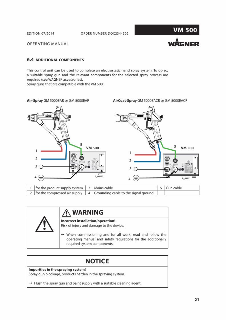
This control unit can be used to complete an electrostatic hand spray system. To do so, a suitable spray gun and the relevant components for the selected spray process are required (see WAGNER accessories).Spray guns that are compatible with the VM 500:
Air-Spray GM 5000EAR or GM 5000EAF AirCoat-Spray GM 5000EACR or GM 5000EACF
VM 500 VM 500
1 for the product supply system 3 Mains cable 5 Gun cable2 for the compressed air supply 4 Grounding cable to the signal ground
6.4 ADDITIONAL COMPONENTS
Incorrect installation/operation!
Risk of injury and damage to the device.
When commissioning and for all work, read and follow the operating manual and safety regulations for the additionally required system components.
WARNING
Impurities in the spraying system!
Spray gun blockage, products harden in the spraying system.
Flush the spray gun and paint supply with a suitable cleaning agent.
NOTICE
22
VM 500
OPERATING MANUAL
EDITION 07/2014 ORDER NUMBER DOC2344502
It is important for systems safety and to achieve an optimum coating, that all system components such as work pieces, conveyors, paint supply, control unit and booth or spraying stand are perfectly grounded.
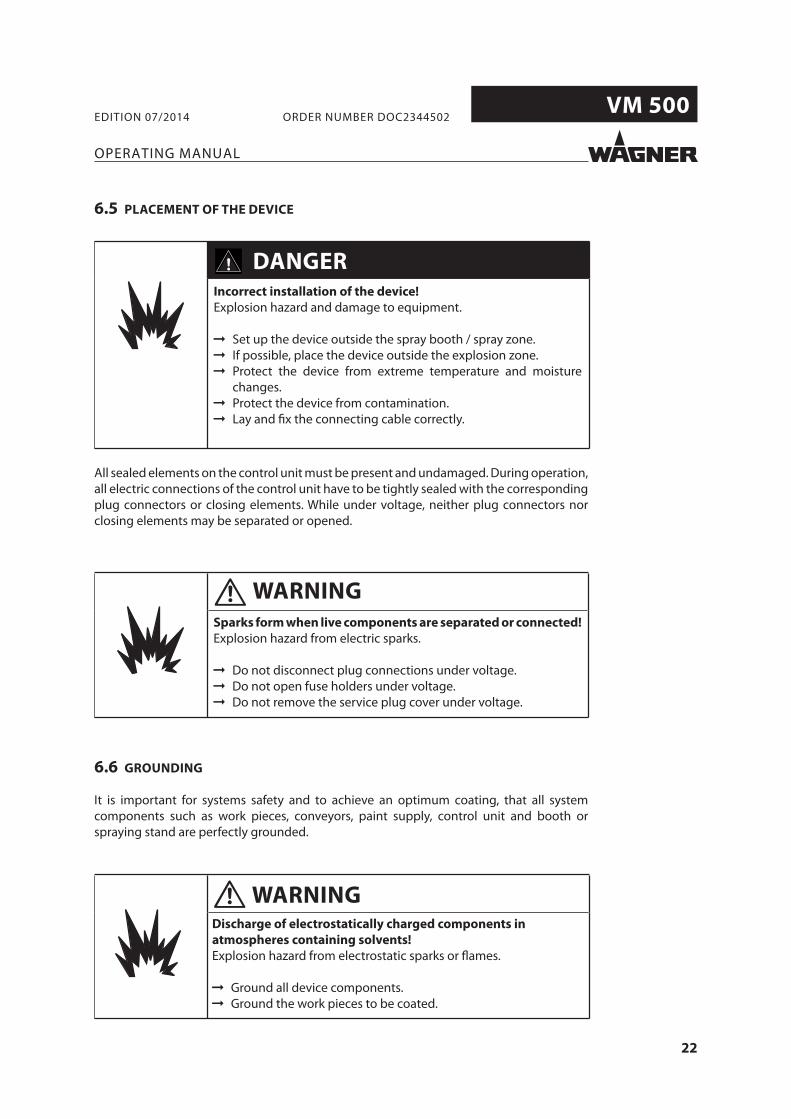
6.5 PLACEMENT OF THE DEVICE
All sealed elements on the control unit must be present and undamaged. During operation, all electric connections of the control unit have to be tightly sealed with the corresponding plug connectors or closing elements. While under voltage, neither plug connectors nor closing elements may be separated or opened.
Discharge of electrostatically charged components in
atmospheres containing solvents!
Explosion hazard from electrostatic sparks or fl ames.
Ground all device components. Ground the work pieces to be coated.
WARNING
6.6 GROUNDING
Sparks form when live components are separated or connected!
Explosion hazard from electric sparks.
Do not disconnect plug connections under voltage. Do not open fuse holders under voltage. Do not remove the service plug cover under voltage.
WARNING
Incorrect installation of the device!
Explosion hazard and damage to equipment.
Set up the device outside the spray booth / spray zone. If possible, place the device outside the explosion zone. Protect the device from extreme temperature and moisture
changes. Protect the device from contamination. Lay and fi x the connecting cable correctly.
DANGER
23
VM 500
B_03234
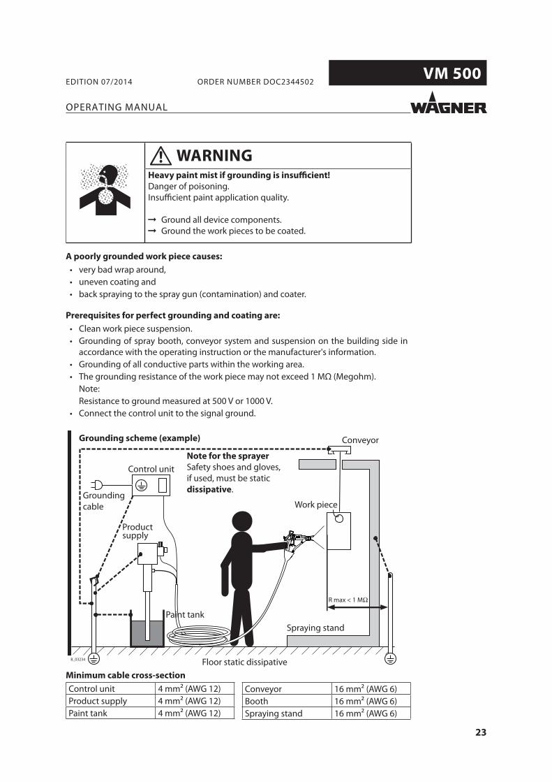
R max < 1 MΩ
OPERATING MANUAL
EDITION 07/2014 ORDER NUMBER DOC2344502
Minimum cable cross-section
Control unit 4 mm2 (AWG 12)Product supply 4 mm2 (AWG 12)Paint tank 4 mm2 (AWG 12)
Grounding scheme (example) Conveyor
Control unit
Grounding cable
Spraying stand
Floor static dissipative
Work piece
Product supply
Paint tank
A poorly grounded work piece causes:
very bad wrap around,uneven coating andback spraying to the spray gun (contamination) and coater.
Prerequisites for perfect grounding and coating are:
Clean work piece suspension.Grounding of spray booth, conveyor system and suspension on the building side in accordance with the operating instruction or the manufacturer's information.Grounding of all conductive parts within the working area.The grounding resistance of the work piece may not exceed 1 MΩ (Megohm).Note:Resistance to ground measured at 500 V or 1000 V.Connect the control unit to the signal ground.
Note for the sprayer
Safety shoes and gloves, if used, must be static dissipative.
Conveyor 16 mm2 (AWG 6)Booth 16 mm2 (AWG 6)Spraying stand 16 mm2 (AWG 6)
Heavy paint mist if grounding is insuffi cient!
Danger of poisoning.Insuffi cient paint application quality.
Ground all device components. Ground the work pieces to be coated.
WARNING
24
VM 500
VM 500
7
6
8
45
9
17
1
21615
14
21
12
11
10
B_03422
3
13
19
20
3
18
OPERATING MANUAL
EDITION 07/2014 ORDER NUMBER DOC2344502
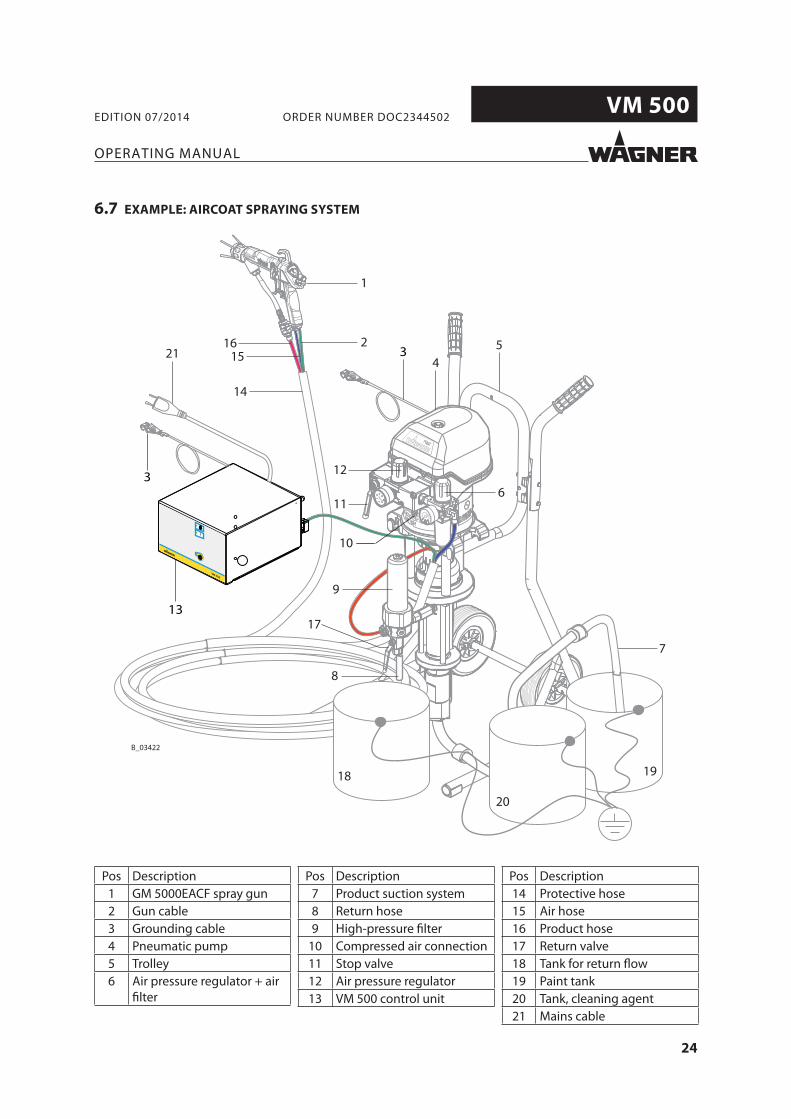
6.7 EXAMPLE: AIRCOAT SPRAYING SYSTEM
Pos Description1 GM 5000EACF spray gun2 Gun cable3 Grounding cable4 Pneumatic pump5 Trolley6 Air pressure regulator + air
fi lter
Pos Description7 Product suction system8 Return hose9 High-pressure fi lter
10 Compressed air connection11 Stop valve12 Air pressure regulator13 VM 500 control unit
Pos Description14 Protective hose15 Air hose16 Product hose17 Return valve18 Tank for return fl ow19 Paint tank20 Tank, cleaning agent21 Mains cable
25
VM 500
OPERATING MANUAL
EDITION 07/2014 ORDER NUMBER DOC2344502
The following points should be noted before commissioning:
Lay grounding cable from the grounding screw on the device to the signal ground and ensure that all other conductive parts within the working area are grounded.
Connect the VM 500 electrostatic control unit via the mains cable to the socket interlocked with the extraction system.
Connect the gun cable to the connector socket and screw into place.
Connect the gun to the adjustable, clean air supply.Compressed air quality class 3.5.2 according to ISO 8573.1.
Connect the GM 5000EA or GM 5000EAC to the paint supply as described in the relevant operating manuals.
Check that all product-conveying connections are correctly connected.
Check that all air-conveying connections are correctly connected.
Visually check the permissible pressures for all the system components.
Check the level of the separating agent in the pump and fi ll up if necessary.
Provide product tank, tanks for fl ushing agent and an empty tank for return fl ow.
The interface input on the back of the control unit has to be protected by the cover.
Connect the system to the air supply.
When fi rst commissioning the unit -> Clean the system in accordance with the operating manuals for the other components.
26
VM 500
OPERATING MANUAL
EDITION 07/2014 ORDER NUMBER DOC2344502
7 OPERATION
Observe safety instructions in Chapter 4.
7.1 TRAINING THE OPERATING STAFF
7.2 SAFETY INSTRUCTIONS
Incorrect operation!
Risk of injury and damage to the device.
The operating staff must be qualifi ed to operate the entire system. Before work commences, the operating staff must receive
appropriate training.
WARNING
Incorrect operation!
Risk of injury and damage to the device.
If contact with solvent-based paints or cleaning agents causes skin irritation, appropriate precautionary measures must be taken, e.g. wearing protective clothing.
The footwear worn by operating staff must comply with EN ISO 20344. The measured insulation resistance must not exceed 100 MΩ.
The protective clothing, including gloves, must comply with EN ISO 1149-5. The measured insulation resistance must not exceed 100 MΩ.
WARNING
Discharge of electrostatically charged components in
atmospheres containing solvents!
Explosion hazard from electrostatic spark-over.
Use gun only with fi tted nozzle, air cap and union nut.
WARNING
27
VM 500
B_03423
VM 500
2
OPERATING MANUAL
EDITION 07/2014 ORDER NUMBER DOC2344502
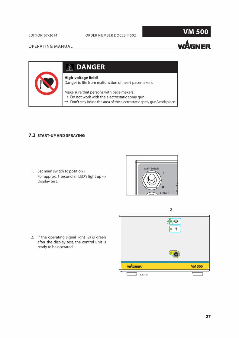
7.3 START-UP AND SPRAYING
1. Set main switch to position I.For approx. 1 second all LED's light up -> Display test.
2. If the operating signal light (2) is green after the display test, the control unit is ready to be operated.
High-voltage fi eld!
Danger to life from malfunction of heart pacemakers.
Make sure that persons with pace makers: Do not work with the electrostatic spray gun. Don't stay inside the area of the electrostatic spray gun/work piece.
DANGER
28
VM 500
B_03423
VM 500
34
B_03423
VM 500
1
OPERATING MANUAL
EDITION 07/2014 ORDER NUMBER DOC2344502
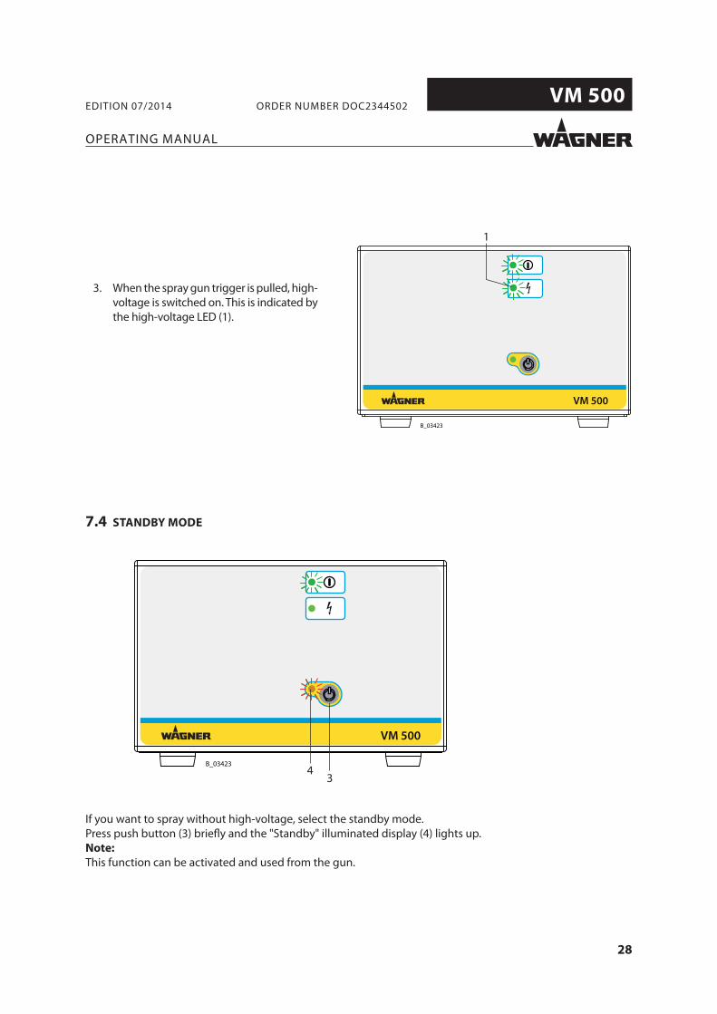
If you want to spray without high-voltage, select the standby mode.Press push button (3) briefl y and the "Standby" illuminated display (4) lights up.Note:
This function can be activated and used from the gun.
7.4 STANDBY MODE
3. When the spray gun trigger is pulled, high-voltage is switched on. This is indicated by the high-voltage LED (1).

29
VM 500
B_03423
VM 500
1 2
34
OPERATING MANUAL
EDITION 07/2014 ORDER NUMBER DOC2344502
8 TROUBLESHOOTING AND RECTIFICATION
Functional fault Cause Remedy
Green illuminated display (2) does not light up
Mains supply not switched on Check and switch on mains supplyFuses defective Replace fuses
No illuminated display lights up Wagner Service
Green illuminated display (1) does not light up, no high-voltage
Spray gun cable not connected or defective
Connect spray gun cable
Wagner ServiceSpray gun not connected or defective
Green illuminated display (1) always lights up
Spray gun or control unit defective Wagner Service
Green illuminated display (1) lights up, no high-voltage
Excessive conductivity of the lacquer See operating manual of spray gun
30
VM 500
OPERATING MANUAL
EDITION 07/2014 ORDER NUMBER DOC2344502
10 PRODUCT DISPOSAL
9 MAINTENANCE AND REPAIR
9.1 MAINTENANCE
9.2 REPAIR
The functionality and completeness of the control unit have to be checked regularly. All sealed elements on the control unit must be present and undamaged. During operation, all electric connections of the control unit have to be tightly sealed with the corresponding plug connectors or closing elements.
The leakage tightness of the device has to be checked at least every 3 years. The "Restricted breathing" requirements according to DIN EN 60079-15:2011 have to be fulfi lled. This inspection may only be carried out by an authorized person or by trained Wagner Service Personnel. When carrying out the leakage tightness test, the mains input terminal serves as a test port.
Repairs to the control unit may only be carried out by trained Wagner Service personnel. This also includes opening the control unit.After repair has been completed, the control unit has to be checked for leaks. The "Restricted breathing" requirements according to DIN EN 60079-15:2011 have to be fulfi lled. When carrying out the leakage tightness test, the mains input terminal serves as a test port.
Do not dispose of used electrical equipment with household
refuse!
In accordance with European Directive 2002/96/EC on the disposal of used electrical equipment and its implementation in national law, this product may not be disposed of with the household refuse, but must be recycled in an environmentally correct manner.Wagner or one of our dealers will take back your used Wagner electric or electronic equipment and will dispose of it for you in an environmentally-friendly way. Please contact one of our service points, one of our representatives or us directly to arrange this.
NOTICE
Sparks form when live components are separated or connected!
Explosion hazard from electric sparks.
Do not disconnect plug connections under voltage. Do not open fuse holders under voltage. Do not remove the service plug cover under voltage.
WARNING
31
VM 500
B_03735
OPERATING MANUAL
EDITION 07/2014 ORDER NUMBER DOC2344502
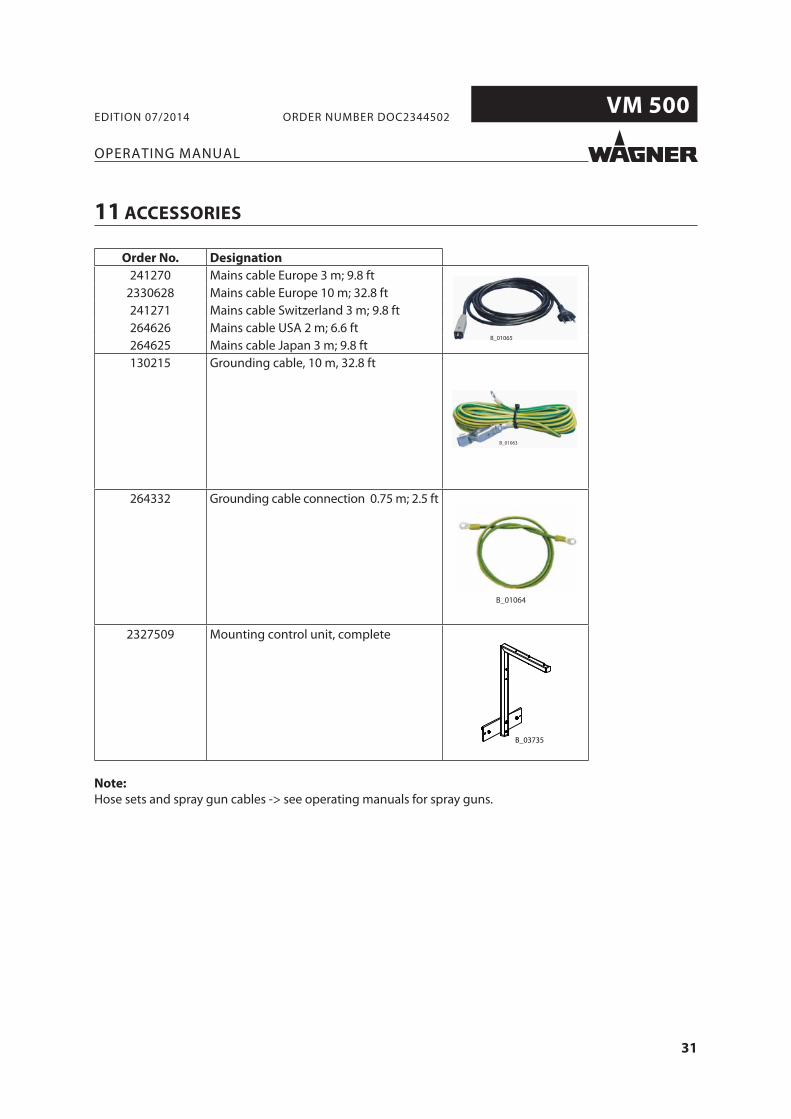
11 ACCESSORIES
Order No. Designation
241270 Mains cable Europe 3 m; 9.8 ft2330628 Mains cable Europe 10 m; 32.8 ft241271 Mains cable Switzerland 3 m; 9.8 ft264626 Mains cable USA 2 m; 6.6 ft264625 Mains cable Japan 3 m; 9.8 ft130215 Grounding cable, 10 m, 32.8 ft
264332 Grounding cable connection 0.75 m; 2.5 ft
2327509 Mounting control unit, complete
Note:
Hose sets and spray gun cables -> see operating manuals for spray guns.
32
VM 500
OPERATING MANUAL
EDITION 07/2014 ORDER NUMBER DOC2344502
12 SPARE PARTS
12.1 HOW CAN SPARE PARTS BE ORDERED?
Always supply the following information to ensure delivery of the right spare part:
Order number, designation, and quantity
The quantity need not be the same as the number given in the quantity column " " on the lists. This number merely indicates how many of the respective parts are used in each component.
The following information is also required to ensure smooth processing of your order:Billing addressDelivery addressName of the person to be contacted in the event of any queriesType of delivery (normal mail, express delivery, air freight, courier etc.)
Identifi cation in spare parts lists
Explanation of column " " (labeling) in the following spare parts lists:
Wearing partsNote: No liability is assumed for wearing parts.
Not part of the standard equipment but available as a special accessory.
Incorrect maintenance/repair!
Risk of injury and damage to the device.
Have repairs and part replacements be carried out only by specially trained staff or a WAGNER service center.
Before all work on the device and in the event of work interruptions:
- Switch off the energy/compressed air supply. - Relieve the pressure from the spray gun and device. - Secure the spray gun against actuation.
Observe the operating instructions for any work.
WARNING
33
VM 500
Spannung:Voltage: Strom: Current:
max. 20Vpp max. 1,0A
Typ / Type:
VM 500
115VAC - 240VAC
50Hz / 60Hz
2344481
max. 40W
J. WAGNER AG
Industriestrasse 22
CH - 9450 Altstätten
Made in Switzerland
Serie Nr.: Serial No.: Spannung:Voltage:
Artikel Nr.: Article No.:
Eingangsleistung:
Input Power:Eingangsstrom:
Input Current:max. 0.5A
I
0
Main Switch
Prim. 1.0 AT
Nicht unter S
pannung trennen!
Avertissem
ent - Ne pas débrancher
sous tension!
Do not disconnect under voltage!
Schutzklasse:Protection Class:IP 54
32
B_04172
19
20
2122
23
34
24
26
29
30
33
3132
6
17 18
16
1514
13
12
1
11
35
10
7
98
45
OPERATING MANUAL
EDITION 07/2014 ORDER NUMBER DOC2344502
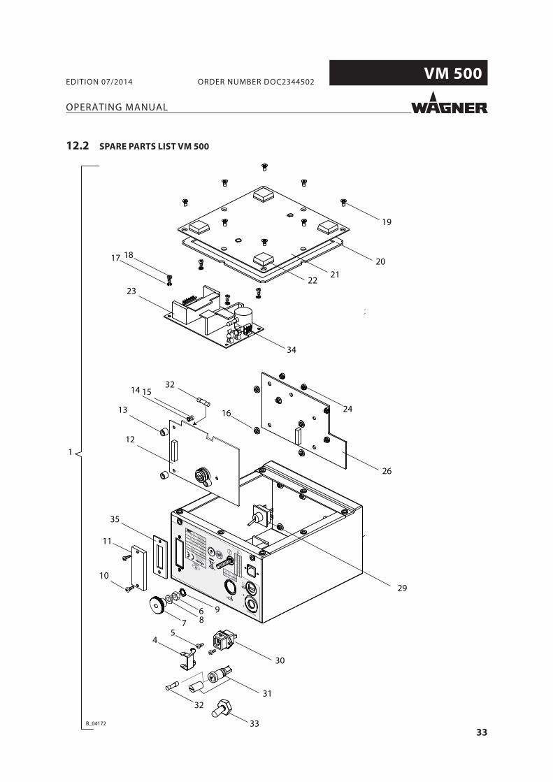
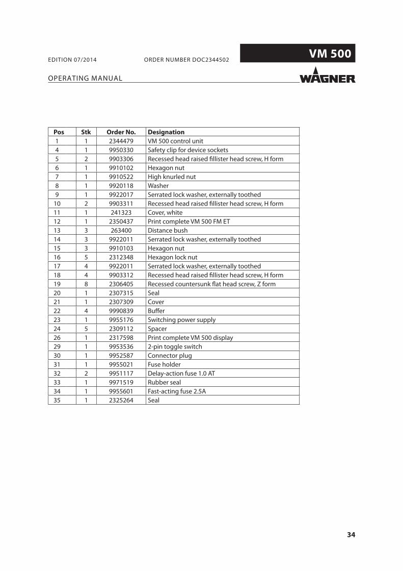
12.2 SPARE PARTS LIST VM 500
34
VM 500
OPERATING MANUAL
EDITION 07/2014 ORDER NUMBER DOC2344502
Order No. Designation
1 1 2344479 VM 500 control unit4 1 9950330 Safety clip for device sockets5 2 9903306 Recessed head raised fi llister head screw, H form6 1 9910102 Hexagon nut7 1 9910522 High knurled nut8 1 9920118 Washer9 1 9922017 Serrated lock washer, externally toothed
10 2 9903311 Recessed head raised fi llister head screw, H form11 1 241323 Cover, white12 1 2350437 Print complete VM 500 FM ET13 3 263400 Distance bush14 3 9922011 Serrated lock washer, externally toothed15 3 9910103 Hexagon nut16 5 2312348 Hexagon lock nut17 4 9922011 Serrated lock washer, externally toothed18 4 9903312 Recessed head raised fi llister head screw, H form19 8 2306405 Recessed countersunk fl at head screw, Z form20 1 2307315 Seal21 1 2307309 Cover22 4 9990839 Buff er23 1 9955176 Switching power supply24 5 2309112 Spacer26 1 2317598 Print complete VM 500 display 29 1 9953536 2-pin toggle switch30 1 9952587 Connector plug31 1 9955021 Fuse holder32 2 9951117 Delay-action fuse 1.0 AT33 1 9971519 Rubber seal34 1 9955601 Fast-acting fuse 2.5A35 1 2325264 Seal
35
VM 500
OPERATING MANUAL
EDITION 07/2014 ORDER NUMBER DOC2344502
13 WARRANTY
13.1 IMPORTANT NOTES REGARDING PRODUCT LIABILITY
13.2 WARRANTY CLAIM
Full warranty is provided for this device:We will at our discretion repair or replace free of charge all parts which within 24 months in single-shift, 12 months in 2-shift or 6 months in 3-shift operation from date of receipt by the purchaser are found to be wholly or substantially unusable due to causes prior to the sale, in particular faulty design, defective materials or poor workmanship.The type of warranty provided is such that the device or individual components of the device are either replaced or repaired as we see fi t. The resulting costs, in particular shipping charges, road tolls, labour and material costs will be borne by us except where these costs are increased due to the subsequent shipment of the device to a location other than the address of the purchaser.We do not provide warranty for damage that has been caused or contributed to for the following reasons:Unsuitable or improper use, faulty assembly or commissioning by the purchaser or a third party, normal wear, negligent handling, defective maintenance, unsuitable coating products, substitute products and the infl uence of chemical, electrochemical or electrical agents, except when the damage is attributable to us.Abrasive coating products such as red lead, emulsions, glazes, liquid abrasives, zinc dust paints and so forth reduce the service life of valves, packings, spray guns, nozzles, cylinders, pistons etc. Wear and tear due to such causes are not covered by this warranty.Components that have not been manufactured by WAGNER are subject to the original warranty of the manufacturer.Replacement of a component does not extend the period of warranty of the device.The device should be inspected immediately upon receipt. To avoid losing the warranty, we or the supplier company are to be informed in writing about obvious faults within 14 days upon receipt of the device.We reserve the right to have the warranty compliance met by a contracting company.The services provided by this warranty are dependent on evidence being provided in the form of an invoice or delivery note. If the examination discovers that no warranty claim exists, the costs of repairs are charged to the purchaser.It is clearly stipulated that this warranty claim does not represent any constraint on statutory regulations or regulations agreed to contractually in our general terms and conditions.
J. Wagner AG
As a result of an EC regulation eff ective from January 1, 1990, the manufacturer shall only be liable for his product if all parts originate from him or are approved by him, and if the devices are properly mounted, operated and maintained.The manufacturer will not be held liable or will only be held partially liable if third-party accessories or spare parts have been used.With genuine WAGNER accessories and spare parts, you have the guarantee that all safety regulations are complied with.

36
VM 500
OPERATING MANUAL
EDITION 07/2014 ORDER NUMBER DOC2344502

37
VM 500
OPERATING MANUAL
EDITION 07/2014 ORDER NUMBER DOC2344502
38
VM 500
OPERATING MANUAL
EDITION 07/2014 ORDER NUMBER DOC2344502

CERTIFIE
D
Order No. 2344502Edition 07/2014
Germany
PhoneFaxE-mail
Switzerland
PhoneFax
More contact adresses on the Internet at:
Company/Locations/WAGNER worldwide
Subject to changes without notice
Doc
umen
t No.
111
6374
6Ve
rsio
n -