electronic service tools - insite.cummins.com selection & ecm/pdd code search work orders, ......
TRANSCRIPT

INSITE™ Overview
Electronic Service Tools2018 VersionPublic Information

Contents Getting Started Launching & Licensing Configuring Options ECM Multi-Level Security ECM Connections Fault Codes & Fault Information System Data Monitor Logger ECM Diagnostic Tests & Advanced ECM Data Features & Parameters Calibration Selection & ECM/PDD Code Search Work Orders, ECM Images & Templates Trip Information Audit Trail Inquire Data Extraction OBD Monitors Expert Diagnostic System (EDS) J1939 Datalink Messages Guidanz Web (formerly CSS) Support
2

Getting Started Windows-based PC obtained that meets or exceeds system
requirements Latest version of INSITE installed
– Includes License Configuration Tool
Latest version of Update Manager installed RP1210 adapter (such as INLINE 7) with connection cables
available for use Appropriate licensing purchased through authorized distributor If any of these steps are not done, please contact your local distributor for
further assistance.3

System Requirements (as of Jan 2018)Component Recommended Minimum Requirements to Install
Platform: INTEL i5 Processor & AMD K10 Core (32bit or 64bit) INTEL i3 Processor & AMD K10 Core (32bit or 64bit)
Operating System:Windows 10 (32bit or 64bit)*Windows 8.X (32bit or 64bit)* - Windows 8.x Starter or Windows 8.X RT are not supported
Windows® 7 (32bit or 64bit)Note: Windows 7 Starter Edition or Basic Edition, Virtual PC and XP Mode are not supported
Processor: 2.1 GHz or greater Quad-Core 2 GHz or greater Quad-Core
RAM: 12 GB or greater Windows 7 - 8GB
Hard Drive: 2 GB or greater available disk space 2 GB available disk space
Media device (needed for installation in most cases and INCAL): Dual Layer - Double Density DVD-ROM DVD-ROM (may be internal or external as needed for installation)
Display: **Minimum Resolution 1024 x 768 **Minimum Resolution 1024 x 768
Keyboard: 101-Key Enhanced 101-Key Enhanced
Pointing Device: Windows Compatible Device Windows Compatible Device
Multimedia: PCs that will be used for Virtual College training will require multimedia and sound capability Any Windows Compatible Sound Device
Other Software: Adobe Acrobat Reader v9.0 or higherMicrosoft .NET Framework 4.5.2
Acrobat Reader 9.0 or higherMicrosoft .NET Framework v4.5.2
Printer (optional): Windows Compatible Device Windows Compatible Device
Internet connection: DSL / Broadband high-speed DSL / Broadband high-speed
Available Ports: 2x USB 2.0 See datalink adapter manufacturer for port specifications.
** Dual Monitor Displays are not supported
All Software section defines the level of PC Hardware required to run all of these applications.
Minimum installations will limit performance. For optimal performance use the recommended hardware or better.
4

Licensing InformationProduct Based MR/HD Automotive provides access to the EPA 2007 and above on highway engines in North America and the Euro VI engines for Europe which are
listed below.ISM - CM876 ISL9 CM2250ISX - CM871 ISX12/11.9/15 CM2250ISB - CM2150 ISX12 G CM2180 EJISC - CM2150 ISB4.5 CM2350 B104ISL - CM2150D ISB6.7 CM2350 B101ISL G - CM218 ISL9 CM2350 L1010ISB6.7 CM2250 ISX12/15 CM2350 X102/X101ISC8.3 CM2250 Turbo Actuator ControllerAftertreatment Diesel Exhaust Fluid Controller
MR/HD Plus provides access to all applications and engines except High Horsepower (HHP) engines. Service Plus provides access to all engines and applications that INSITE supports.
Functionality Levels Pro is the highest level of functionality that INSITE provides, which includes calibration download.
– NOTE: Requires certification by Cummins distributor to obtain this type of license.
Lite provides all of the functionality of Pro except for calibration download capability. RSGR/Industrial Pro functionality limits the access to Road Speed Governor parameters and Industrial Pro provide calibration download to Industrial
products only. Basic functionality is read only and does not have adjustment or calibration download capability. 5

RP1210 Device Compatibility
Supported– INLINE 7
• NOTE: INLINE 5 & INLINE 6 do work with INSITE, but are no longer supported
– Any RP1210 Compliant Datalink Adapters– Additional information available on insite.cummins.com
6

Launching & Licensing
7

Launching INSITE
After INSITE has been installed, you should have a shortcut icon on your desktop that looks like .
Double-click INSITE shortcut. An INSITE splash screen
should be displayed as shown to the right.
8

Launching INSITE
If no licenses have been activated, a “Welcome to INSITE” window will appear If licenses have already been activated, INSITE will launch
Launches License Configuration Tool
Locate distributor contact information
Launches INSITE in Simulator Mode
NOTE: This window must be closed if “Activate Licenses” is selected to allow licenses to activate properly. 9

Navigating INSITE™ Title Bar
Menu Bar
Tool Bar
View Bar
Minimize / Maximize / Exit
Selected Connection
Communication Status
Connection Status
10

Launching License Configuration Tool (LCT) Standalone utility to manage licenses and
counts for INSITE™ and can be found several ways
Click “Manage Licenses” from the menu bar in INSITE
From the Windows Start Screen or Start Menu– Varies by operating system– For Windows 7 or 10 users, Type “license” into search
bar of Start menu. – For Windows 8 users, type “license” while Start screen is
open.– Click on result “License Configuration Tool” to start
launching.
Through File Explorer– 32-bit OS: C:\Program Files\Cummins Inc\License
Configuration Tool– 64-bit OS: C:\Program Files (x86)\Cummins Inc\License
Configuration Tool
11

Tool Instance Once LCT is launched, you
should obtain a tool instance in the upper-right corner. Tool instances should be unique to each
system. Very important to document the tool
instance in the event of a system crash or sudden replacement.
If a tool instance is not obtained (N/A), it is recommended to contact your I.T. or network administrator to ensure there are no issues with communication being blocked.
If a tool instance is obtained, you should have communication and ability to activate licenses properly.
12

Activating Licenses
Click on Activate Licenses/Counts tab at left of LCT.
There are 2 different methods– Enter activation keys manually– Activate available licenses using QSOL Log In
13

Activating Licenses using Activation Keys Enter license activation keys manually, one at a
time After activation key has been entered, click
“Activate” button A window will appear showing “Activating
Licenses…” Once license is activated successfully, you will see
a prompt. Repeat this process as needed to activate all
licenses issued.– A Basic & Functional license key is required for full
functionality
14

Activating Licenses using QSOL Log In If you have a Quickserve (QSOL) account and the licenses have been
registered to your QSOL ID, you can click on “Log In” button to start activation.
Once logged in, any licenses available for activation, will be displayed.
– Any licenses already activated will not appear when logged in.
Select the desired licenses, then click “Activate” to continue. You will then be prompted to confirm activation of selected items. Once selection is confirmed, licenses will begin to activate and
prompt to review after activation is successful.
15

Viewing Active Licenses & Counts
Once licenses are activated, you can click on “View Active Licenses/Counts” tab and licenses should display as shown.
After licenses are initially activated, INSITE can be launched again.
16

Additional Resources
How to Activate Licenses and Counts
How to Repair and Revalidate your Licenses
Offline License Operations
How to Transfer Licenses and Counts
For additional information on other functions of LCT, please view the tutorial videos using the links provided below.
17

Configuring Options
18

How to Configure Options in INSITE™• In the menu bar, navigate to Tools > Options• The Options dialog screen should appear
19

Calibration Selection Options
Calibration Selection Settings– Enable/Disable Auto Detect– View Network Calibration
Drives– Enable/Disable Automated
ECM Code Search
Modify network proxy settings
20

Connections Options
Allows user to add and remove datalink adapters and simulators used for connections.
Existing connections can be renamed through Properties.
21

File Options Allows user to modify location
paths for saved items such as…– Calibration Logs– Data Monitor/Logger Logs– Exported images, templates and logs– Imported images, templates and logs– Inquire Data Extraction files– Work Orders & ECM Images– Templates
Default settings are recommended
22

General Options Start Up
– Display/Hide Splash Screen at launch
Toolbar– Set display button size– Display/Hide Tool Tips
Viewbar– Display/Hide feature names
Key Switch Timer– Enable/Disable
Fault Codes– Set Auto Refresh rate
Reset INSITE to Cummins Default Settings23

Appearance Options
Allows user to customize appearance of…
– text size, font, and color– background colors– grid colors
Appearance options are available when General category is expanded.
24

Inquire Data Extraction Options
Select options for connection settings
Select operations for Inquire Data Extraction resets
Modify output file to save as either .csv or .txt
25

Units of Measure Options
Allows user to modify units of measure to predefined or custom settings.
26

User Manager Options Enables a system administrator
to assign specific access rights to individual users and groups
When enabled, a login is required to open INSITE™
Multiple users and groups can be created
27

User Manager Groups Options
Add, remove or modify group rights
Create custom group rights
28

Users Options Add and remove users
Modify user accounts
Assign new users to group
29

Work Orders Options
Enable/Disable Work Order Mode– Enabled is recommended
Predefine Site Location & Cummins Service Provider Code
Enable/Disable Cummins Inc. data collection
When Work Order Mode is enabled and no compatible Work Orders exist, a New Work Order dialog will be displayed after connection to the ECM is established.
30

ECM Multi-Level Security
31

ECM Passwords Most Cummins ECMs have 5 levels of password
capability– Master
• Master password allows all writes, adjustments and resets• If Master password is set, but not entered
– No Changes to ECM allowed
– Adjustment• Master password must also be set• Only allows changing ECM adjustments• Features and parameters
– Reset• Master password must also be set• Only allows ECM resets• Fault Codes & Trip Information
– OEM & OEM 2• Master password does not need to be set• Protects OEM specific parameters from adjustment
– Greenhouse Gas• Do not use unless directed by Cummins Inc. 32

ECM Passwords Used to protect the ECM from users
attempting to make unauthorized adjustments
Different levels can be set to allow for:– Resets only (Reset Password)– Feature Adjustments (Adjustment Password)– Full functionality (Master Password)
Master password must be set when using ECM security
INSITE will operate in read-only mode if appropriate password is not provided during ECM connection.
33

ECM Password Removal (Zap-IT) To remove ECM and OEM passwords:
– Select Tools> ECM Password Removal... on the menu bar. The ECM Password Removal window will appear. This window is also called the ZAP-IT window.
– Select the type of ECM Passwords to be removed.– Select ZAP-IT. The ECM Password Removal Confirmation window will
appear.– Select Yes and follow the prompts to remove the ECM passwords.– The ECM Password Removal window will display the number of counts
remaining, if any.– Select Cancel to close the ECM Password Removal screen.
Zap-IT passwords are entered using the Cummins License Configuration Tool (LCT)
Zap-IT Counts can be obtained from local Distributors
34

ECM Connections
35

Adding New Connection Click on connection Select “Add New…” Dialog box for ECM Connection
Wizard should appear as shown.
Click “Next” to continue.
36

Adding New Connection Select appropriate connection.
– Auto Configure• Automatically detects installed
datalink adapters
– RP1210 Adapters• Manually configure the datalink
adapter connection
– Simulator• Creates simulated ECM
environment using virtual port
Click “Next” to continue.
37

Auto Configure Auto Configure will
automatically detect and connect to an RP1210A compliant adapter that is installed on the PC
Select Auto Configure and click the Next button
Ensure that the steps listed in the Instructions have been completed
Click the Start button
38

Auto Configure Auto Configure will
attempt to detect and connect to an RP1210A compliant adapter
This can take several minutes to complete
To cancel the process, click the Stop button, otherwise let it run until it completes
39

Auto Configure Auto Configure
process was successful
Click on the Next button to continue
Select the desired adapter configuration
Click on the Next button to continue
40

RP1210 Adapters Select desired vendor Select desired adapter
– Ensure correct connection type is selected (such as USB, Bluetooth, Wireless, or COM port)
Select protocol– Auto Detect, J1939 or J1708
If desired, you may click “Datalink Adapter Connection Test” to validate driver installation
Once successful, click on “Next” to continue
41

Simulator Simulates connections to all supported
engines– Almost full simulated tool functionality– Can be used for training or exploring Engine
Features without being connected to an Engine– Data is simulated and does not represent actual
engine data
Classic simulator options available for pre-EPA 2007 engines
Integrated simulator options available for EPA 2007 and newer engines.
– INSITE Integrated Simulator – Multi Module• Simulates multi-module set up
– INSITE Integrated Simulator – Single Module• Simulates single module set up
42

Adding New Connection
Enter a desired name for the new connection.
Click “Next” to continue.
43

Adding New Connection If desired, select
corresponding checkbox to make connection active.
If desired, select corresponding checkbox to setup/add another connection.
Click “Finish” NOTE: If another connection is not
being created and connection is made active, the Connect to ECM dialog box will appear after finish.
44

Adding New Connections
Additional connections or simulators can be added by navigating the Menu Bar– Tools > Options > Connections– File > Connections > Add New Connection…
45

Selecting Connections Select connection from
dropdown. Connect dialog box should
appear after selecting desired connection.
46

Connecting to ECM Use the left View Bar “Connect to
ECM” icon Click on Tool Bar icon From Menu Bar, click on Tools
Connect to ECM Use keyboard key shortcut Ctrl+E IMPORTANT NOTE: Always ensure
the desired adapter is selected before attempting to connect to the ECM
47

Connecting to ECM
Clicking “Connect” button will start establishing datalink connection to ECM.
48

Fault Codes
Fault Information Systems
49

Fault Codes Fault Codes window displays an engine's fault data Each fault is represented by a Cummins fault code
Indicates a specific malfunction or abnormal condition within the controller, subsystem, or engine
50

Fault Codes Additional data can be viewed for each fault code by clicking to expand the fault
51

Fault Information System Fault Codes window provides
link to troubleshooting information
Accessed by right-clicking on a displayed fault and selecting “Fault Trees Troubleshooting Steps”
Right-click menu also allows sorting and printing fault codes
52

Fault Information System
Follow steps accordingly in troubleshooting information.
53
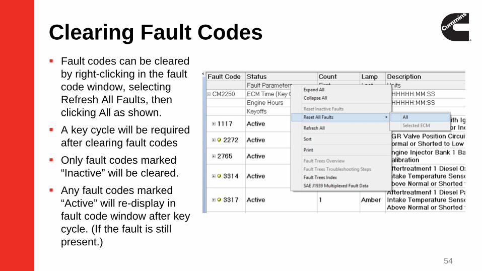
Clearing Fault Codes Fault codes can be cleared
by right-clicking in the fault code window, selecting Refresh All Faults, then clicking All as shown.
A key cycle will be required after clearing fault codes
Only fault codes marked “Inactive” will be cleared.
Any fault codes marked “Active” will re-display in fault code window after key cycle. (If the fault is still present.)
54

Data Monitor / Logger
55

Data Monitor / Logger Predefined and
Custom Parameter Groups available to allow common monitors to be selected quickly
56

Data Monitor / Logger Ability to select
all monitor parameters available or select monitor parameters individually
57

Data Monitor / Logger Ability to view
minimum and maximum measured values of values read by INSITE while the parameters are being monitored
58

Data Monitor / Logger Method to view or log live engine data at a user defined sample rate. Monitor data:
• View selected parameters to display• Start\Resume • Pause• Stop
Log data:• Continuous logged data for each parameter selected and saved to a file for analysis
Snapshot: Single data point logged for each parameter selected and saved to a file for analysis
Start Graphical Monitoring Graphical Monitoring for up to six (6) parameters
Set Sampling Rate User settings for parameter sample rate
Setup Event Marker Used to setup event markers to mark events in log files
59

Data Monitor / Logger An event can be marked while logging in the main Data Monitor / Logger
screen, or when in Graphical Monitoring, by pressing the spacebar This provides the option to enable or disable the Event Marker as well as
providing the option to create comments for event markers The Log file contains the Event Marker Description. Data Monitor/Logger provides a means to View, Log or Snapshot live
engine data Log and Snapshot files can be saved as a CSV or Tab delimited (.txt) files for analysis in Excel The Data Monitor/Logger appearance can be modified through Tools Options to display data in a larger font
60

Graphical Monitoring Graphical Monitoring is a
way to display, log, print, and save data for up to six parameters in a graph
Graphical Monitoring visually monitors and plots multiple parameters into a graphical display
Graphical Monitoring also supports importing graphical logs and playback of the log
61

Data Monitor / LoggerConverting a Log file for external use:
– Generate a Log File– Save the Log File
• INSITE prompts to save once Stop has been selected in Data Monitor/Logger
• The log files or the snapshot files are saved as Comma Separated Value (CSV) files
• This file is saved to the hard drive in the C:\Intelect\Insite\Logs Directory or to the drive INSITE is installed
• User Comments can be added to the Log File
62

Diagnostic Tests
Advanced ECM Data
63

Diagnostic Tests Displays tests
available for the connected engine
Each engine supports different diagnostic tests
Select the desired test and click the “Next” button
Always follow the directions of each test carefully
64

Advanced ECM Data Displays the special features
available for the connected engine
Each engine supports different special features
Select the desired special feature
Always follow the directions of each feature carefully
65

Features & Parameters
66

Features & Parameters
Allows licensed user to make changes to ECM settings Multiple adjustments can
be done at one time Tool Tips are available
that help in adjusting parameters and viewing limits Feature group categories
can be expanded or collapsed to adjust parameters
67

Features & Parameters
Available features and parameters displayed are calibration based and will vary by engine family
Parameters are a subset of features
Adjustable features and parameters will be displayed with or icons
Selected features and parameters will be displayed with the or icons
Some features and parameters may be locked and are indicated by or icons
68

Features & Parameters To change a parameter, navigate to the desired feature In the ECM Value column, enter or select the desired value
–The new value should be displayed in the ECM Value column and previous value will be displayed in the Original Value column.
Once all changes are made, right click in the Features and Parameters window and select Send To > ECM or click the “Send to ECM” button in the menu barSelect OK in the Confirm ECM Adjustment window to confirm saving changes.
– Key cycle will be required after changes are saved to ECM
69

Features and Parameters for Multi-Module ECM(s)
When connecting to a multi-module ECM you will see the primary and secondary ECM(s) in Features and Parameters.
70

Features & Parameters Limits can be viewed by selecting
“Limits” from the right-click menu within the Features and Parameters window.
Limits will display the name as well as both minimum and maximum limits for the selected parameter.
71

Calibration Selection
ECM/PDD Code Search
72

Calibration Selection
Provides ability to update the configuration or change the rating of an engine– Requires Pro functionality license
Products are sorted into groups– Automotive– Industrial– HHP/PowerGen– Programmable Datalink Device (PDD)
73

Calibration Selection Calibrations are detected in INSITE when INCAL DVD icon
is displayed next to folder or drive
74

Adding Certification Codes
Certification Codes will need to be selected prior to calibration download being performed initially.
– Right-click the engine name– Select “Certification Codes”
Certification Codes can also be selected from Tools>Calibration Selection>Certification Codes…
75

Add/Remove Certification Codes
Adding/Removing Certification Codes can be done in several ways
– Select desired certification codes from the list, then click the “Add/Remove Selected” button
– Click the “Add/Remove All” button
Add Selected
Add All
Remove All
Remove Selected
76
Fleet Counts
A Fleet Count is not required when:– Calibrating an ECM to a new ECM Code revision– Superseding ECM Codes
A Fleet Count is required when:– Calibrating a ROM booted ECM– Calibrating a New or RECON ECM– Changing to a different ECM Code
Fleet Count passwords are entered using the Cummins License Configuration Tool (LCT)
Fleet Counts can be obtained from local Distributors
77

Performing A Calibration Download Connect to ECM Open Calibration Selection and select ECM\PDD button If Auto-Detect is enabled, INSITE will automatically detect the calibration code currently
in the ECM. If Auto-Detect is not enabled, locate desired calibration in Calibration Workspace or
other location (such as INCAL DVD or network drive)– Requires downloading calibration from ECM Code Search in INSITE or through Quickserve
Select calibration Right-click on calibration and select “Transfer to ECM”
78

Performing A Calibration Download Click the Next button on the
Calibration Download Wizard window
Review the System ID and Dataplate information
– Dataplate information can be edited in this window
– The Restore Original Values button will undo all edits made
– The Save/Restore Adjustable Parameters box is checked by default. (Recommended)
Click the Next button
79

Performing A Calibration Download Verify the information in the
Summary window Click the Next button to
continue Review the Adjustment
Confirmation window– Anytime, up to this point, you can cancel
the download and go back
Click on the OK button to continue
80

Performing a Multi-Module Calibration Download
When connected to a primary and one or more secondary ECM(s), you will be prompted to select one of the following options:
– Calibrate Engine Control System (Single Key-Off)
– Calibrate Engine Control System (Multiple Key-Off)
– Calibrate Single ECM
81

Performing a Multi-Module Calibration Download
When using either the Calibrate Engine Control System (Single Key-Off) or the Calibrate Engine Control System (Multiple Key-Off) options, INSITE will display compatible secondary calibrations to select during the Select Calibration process.
82

Performing A Calibration Download Calibration Transfer progress windows
Turn off the key switch and click on the OK button to continue
83

Performing A Calibration Download Calibration Transfer Key
Switch progress message Turn on the key switch and
click on the OK button to continue
84

Performing A Calibration Download Calibration Transfer
Results window Click the OK button
to continue Calibration Transfer
Complete window Click on the Next
button to continue
85

Performing A Calibration Download Click on the Finish
button to close the ECM Calibration Download Wizard
86

Performing A PDD Calibration Download Connect to ECM Open Calibration Selection and select ECM\PDD button Right click on Programmable Datalink Device (PDD) and select Autodetect Calibration Or locate desired calibration
– In Calibration Workspace• Requires downloading calibration from ECM Code Search in INSITE or through Quickserve
– INCAL DVD– Network Drive
87

Performing A PDD Calibration Download Autodetect will find
and select the appropriate calibration code for the connected PDD
88

Performing A PDD Calibration Download Right click the desired
calibration code and select “Transfer To Device” or select the “Transfer to ECM” button from the toolbar
89

Performing A PDD Calibration Download On the Calibration
Download Wizard click on the Next button
90

Performing A PDD Calibration Download On the PDD
Calibration window select the device to be calibrated by checking the box
91

Performing A PDD Calibration Download On the PDD
Calibration window, when the “Reflash is completed successfully” message appears, click on the Cancel button or Red X button to close the window and continue
The ECM will reconnect automatically
92

ECM/PDD Code Search ECM Code Search allows
checking for calibration updates and reviewing calibration history regardless of ECM connectivity
– When not connected to ECM, the search box will appear to search for calibration updates by manually entering ECM or PDD Code
– When connected to ECM, you can only check for calibration updates or review calibration history of the connected ECM
93

Using ECM/PDD Code Search Select desired option of ECM or PDD for searching for the calibration code
– ECM (Engine Control Module) or PDD (DEF Controller, Turbocharger Actuator, etc.)
Enter desired ECM/PDD code without revision number– (For example EF10045)
Click on the Search button. Save button will appear as selectable when a calibration is found
– Search status window displays locations searched, location found and save status (if applicable).
94

ECM/PDD Code Calibration History On the ECM/PDD Code Search
window click on the Calibration History button
Review the ECM Calibration Revision History
Click on the Export button to export the information to a .csv file format
95

ECM/PDD Code Calibration History On the Export window, click
the Save button to export the Calibration History
On the Export window, click the Cancel button to cancel and close the window
Click on the OK button to return to the ECM Calibration History window
96

ECM/PDD Code Search On ECM/PDD Code Search
window, click on the Exit button to close the window
97

Work Orders
ECM Images
Templates
98

Work Orders
A Work Order is the top level identifier that contains the ECM image(s).– An image is a copy of the ECM data– May contain multiple images
Work Orders can be used to…– Identify a specific customer, vehicle or equipment – Help track vehicle and equipment repair history
If Work Order Mode is enabled…– Prompted to create “Initial” image when connecting to an ECM– Prompted to create “Final” image when disconnecting from an ECM
“User” images can be manually created under the Work Order while connected to an ECM
99

Work Orders Work Orders can be created
manually by right-clicking in the Work Order pane and selecting “New Work Order” or clicking “New Work Order” in tool bar
If Work Order Mode is enabled and an existing compatible Work Order is detected, INSITE will prompt to select an existing Work Order to use or create a new Work Order
– If a Work Order is not detected, INSITE will only prompt to create new Work Order
Work Order pane
100

Work Orders Can be created manually by the user or automatically when Work Order Mode is enabled When a Work Order is created, an “Initial” ECM image is also created by default When connected to an ECM, only Work Orders compatible with that Engine Serial Number will
be displayed All Work Orders can be viewed when not connected to an ECM Recommended to always create a Work Order, preferably with Work Order Mode enabled
101

Work Orders
Work Order and ECM Image names are defaulted to a Date – Time format
– WO-20180131-145950 = 01/31/2018-2:59:50pm
Image Name and Notes can be edited at the time of creation
Image Name and Notes can be also edited in the right click Properties menu
102

ECM Images
Captures ECM data at creation “Initial” images are created with new Work Order “User” images can be created at any time when connected to an ECM “Final” images are created when disconnecting from ECM and Work
Order Mode is enabled New Images can be created by clicking the “New ECM Image” button
in the tool bar or by selecting “New ECM Image” in right-click menu of selected Work Order
Tool bar icon
103

ECM Images Right-clicking on an existing image also allows you to…
– Export– Analyze– Print– Delete– Send to Mail
104

Emailing ECM Images Right click on the desired ECM
Image Select Send to Mail option INSITE will open the default email
program and attach the files
105

Exporting Images & Templates Select desired Image or Template file File > Export > Image(s) or Template(s)
or Select Export Image(s) or Export Template(s) from right-click menu of image or template
Click Save button to export INSITE images can be exported as the
following file formats– .EIF
• If exported image or template is intended for use on another INSITE
– .CSV• If wanting to view ECM image in Excel
– .TXT• If wanting to view in plain text
INSITE templates can only be exported as .ETF file format
106

Importing Images & Templates
File > Import > Image(s) or Template(s)
Right click on a Work Order and select Import Image(s) or Import Template(s)
Browse to and select desired image or template file
– Images must be in .EIF file format– Templates must be in .ETF file format
Click the Open button to import
107

ECM Image Analyzer ECM Imager Analyzer
is a tool to view all information in an ECM Image in one convenient location
Open Work Orders then right click on an ECM Image and select Analyze Image or select an ECM Image then select File>Analyze Image
The information is displayed in separate tabs
108

Templates
ECM Images also can be converted into a template
– Either select the “Convert to Template(s)” button in menu bar or in right-click menu when desired ECM image is selected
Allows transferring of the same Feature and Parameter setup from a given ECM image to multiple ECMs
Template pane
Tool bar icon
109

Templates After a template has been created, right-click on the selected template to…
– Send to ECM– Export– Print and Print Preview– Delete– Edit
110

Templates
Template name and comments can be customized at time of creation or by going to Properties in right-click menu of selected template
111

Templates ECM Template Editor Allows users to edit
Features and Parameters that can be modified in an ECM Template
112

Templates
Report provided after sending to ECM Advises which parameters were not able to
be written to ECM User can use this to setup the vehicle
accordingly
113

Trip Information
114

Trip Information
115

Trip Information Trip Information continuously monitors and records engine operating data that
tracks engine and driver performance Stored data can be viewed using INSITE™
– Live module– Exported ECM Image
Parameters are grouped differently, according to the ECM Not all ECMs list the same parameters Allows the user to view ECM Values for multiple time periods
– Lifetime of the ECM– Since the Trip Information was last reset
Trip Fuel Report will display all fuel related parameters for the above time periods INSITE™ allows the user to print these screens
116

Trip Information Trip Information may be
printed or print previewed when connected to the ECM or Image Tool Bar Printer Icon File Print
117

Trip Information > Trip Fuel Report A Trip Fuel Report is a
condensed list of fueling parameters Available on any engine that
supports Trip Information Select Apply Custom Filter from
the Tool Bar or right click in the Trip Information window and select Trip Fuel Report Trip Fuel Report can only be
Printed or Print Previewed from this view
118

Audit Trail
119

Audit Trail Tracks and records changes made to ECM
Tool ID (INSITE version) User ID (tool instance) Identifies type of ECM changes
Audit Trail displays the last four or eight times, if supported by the calibration, that the ECM was modified
A single record can contain multiple changes
120

Inquire Data Extraction
121

Inquire Data Extraction
Application for fleets that need to quickly gather vehicle data
Simple connection to vehicles Provides resets as needed Data is automatically formatted for importing
to a spread sheet or data base
122

Inquire Data Extraction To open Inquire Data Extraction click on Inquire Data Extraction on the view bar On the pop up message click the OK button Inquire Data Extraction will close all open views and disconnect from the engine.
123

Inquire Data Extraction Used to quickly extract and store ECM data Reset selected parameters in a connected engine when no active faults or other issues are present Inquire Data Extraction is typically performed while fueling the vehicle Extracted data is saved to a ‘CSV’ (Comma Separated Value) file for future use Click on the Connect button to continue
124

Inquire Data Extraction
1st Time Engine Data Extraction Vehicle information Listed Can be customized for easier
identification Click on the Continue button
125

Inquire Data Extraction Data extraction
in progress
126

Inquire Data Extraction Data extraction
process complete Click on the OK
button to continue
127

Inquire Data Extraction Click on the Options
button to view and set options to customize any further data extractions
128

Inquire Data Extraction From here connection
settings can be changed Reset operations can be
selected The output file type can
be selected Add Selected
Add All
129

Inquire Data Extraction Select the desired
options and click on the Apply button
Remove Selected
Remove All
130

Inquire Data Extraction Click on the OK
button to continue
131

Inquire Data Extraction Click on the
Connect button to perform another data extraction or click on the Close button to exit and return to INSITE
The user will need to reconnect to the engine to use INSITE
132

OBD Monitors
133

OBD Monitors
The OBD system monitors components that can affect the emission performance of the vehicle If supported in the engine calibration
Displays a map of all available fault codes with associated monitor type and its readiness status.
OBD Monitors are never cleared from this view
User can refresh the view
134

Expert Diagnostic System (EDS)
135

Expert Diagnostic System (EDS) Web-based diagnostic/troubleshooting tool Designed to get to the most likely solution quickly
Based on technician feedback and historical service events
Integrated into INSITE to offer single session with connected ECM Cannot be used in conjunction with Guidanz Web
136

J1939 Datalink Messages
137

J1939 Datalink Messages J1939 Datalink Messages displays specific parameter group numbers,
and the information associated with those parameter group numbers. This feature allows the user to view information about specific J1939
messages.
138

Guidanz Web (formerly CSS)
139

Guidanz Web Integration Integrates service information, diagnostic
solutions and associated administrative, diagnostic, accessibility and repair information based on prioritized fault codes
If you are using Guidanz Web, you will be able to launch or return to INSITE from Guidanz Web
If you create a new Work Order image the Guidanz Job order from Guidanz Web will be populated in the Work Order image
Cannot be used in conjunction with Expert Diagnostic System (EDS)
140

Guidanz Web Integration Selecting Tools Prioritized Fault Codes allows you to see a list of
prioritized fault codes
141

Once the Send To Guidanz option is active, the user can click on this option to send ESN (PSN), engine make and model, Work Order image file name, and fault codes in prioritized order to Guidanz Web
INSITE will prompt you if the data was sent to Guidanz Web successfully.
Guidanz Web Integration
142

Support
143

How to Contact Cummins Care Electronic Tools
Phone: 1-800-CUMMINS (1-800-286-6467), select option 2, then 3
Email: [email protected]
Web Chat: https://insite.cummins.com/chat/ChatLogmeinv2.html
Website: http://insite.cummins.com
144