6 - cm2350 electronic controls - scannerdanner
TRANSCRIPT

CM2350 Electronic ControlsISB6.7 CM2350 B101ISL9 CM2350 L101VERSION 1.1
1

CM2350 Control System Overview
ECMECM InputsECM OutputsEngine testsTroubleshooting
2

CM2350 ECM
IdentificationMounting Locations (B, L, & X)Cooling Strategies Air on ISB6.7, ISX12
Fuel on ISL9
Fuel on ISX15
Battery supply & return integrated into the OEM 96 pin connectorIntegrated Aftertreatment DEF Dosing controlMore Datalinked sensor Options96 way connector service
3

FAULT CODES BASICS
4
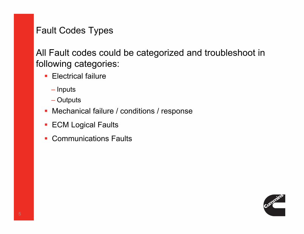
Fault Codes Types
All Fault codes could be categorized and troubleshoot in following categories: Electrical failure
‒ Inputs‒ Outputs
Mechanical failure / conditions / response
ECM Logical Faults
Communications Faults
5

Fault Codes Types
Electrical Failure INPUT Components
‒ Voltage Above Normal, or Shorted to High Source‒ Voltage Below normal, or Shorted to Low Source
OUTPUT Components
‒ Current above normal or grounded circuit‒ Current below normal or open circuit
Mechanical Failure Data erratic, intermittent or incorrect (also could be Communication
failure)
Mechanical system not responding or out of adjustment
Abnormal rate of change
6

Fault Codes Types
ECM Logical Faults Data not Rational
Data erratic, intermittent or incorrect (also could be Mechanical failure)
Data Valid But Above Normal Operating Range‒ Least Severe Level, Moderately Severe Level, Most Severe Level
Data Valid But Below Normal Operating Range‒ Least Severe Level, Moderately Severe Level, Most Severe Level
Condition Exists
Out of Calibration
Communications Faults Received Network Data In Error
Abnormal update rate
Root Cause Not Known
Bad intelligent device or component7

ECM SENSOR READING
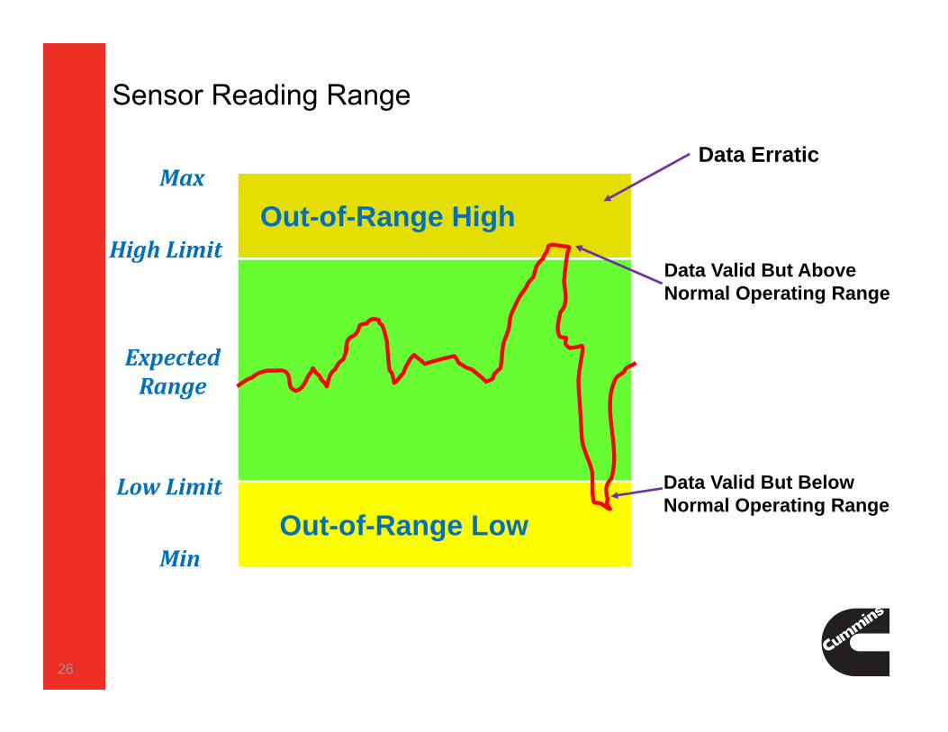
8

Sensor Voltage Range Operation
9
0.25V
0.0 V
5.0V
4.75V
Normal Sensor Operating Range
Out-of-Range High
Out-of-Range Low
Out-of-Range High Fault Code
Out-of-Range Low Fault Code
What is ‘Fault Code State Change’?
‘Fault Code State Change’ is the process of creating the ‘opposite’ fault code to troubleshoot sensors, harnesses, and ECM’s.
Understanding the ‘fault code state change’ logic can make troubleshooting as easy as disconnecting a sensor or unplugging the engine harness from the ECM.
10
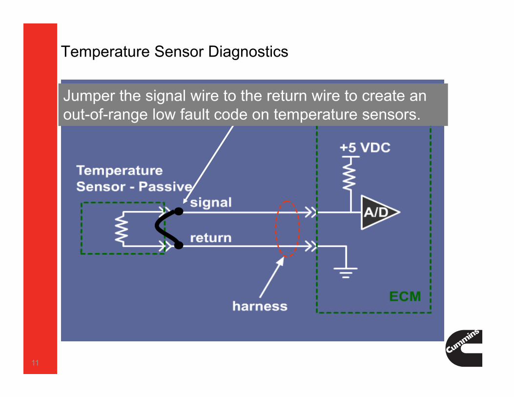
Temperature Sensor Diagnostics
Jumper the signal wire to the return wire to create an out-of-range low fault code on temperature sensors.
11
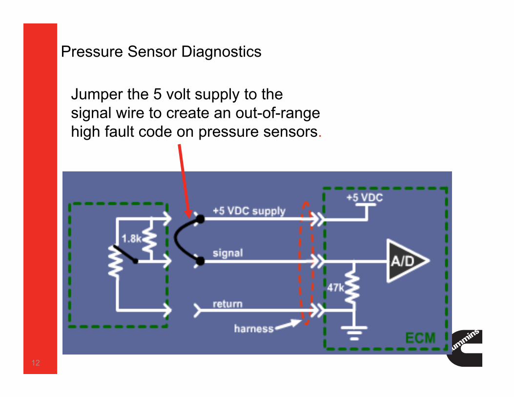
Pressure Sensor Diagnostics
12
Jumper the 5 volt supply to the signal wire to create an out-of-range high fault code on pressure sensors.

Using Test Leads to Change the Fault Code State
13

Using Test Leads to Change the Fault Code State
14

Electrical Failure INPUT Components
‒ Voltage Above Normal, or Shorted to High Source‒ Voltage Below normal, or Shorted to Low Source
OUTPUT Components
‒ Current above normal or grounded circuit‒ Current below normal or open circuit
15
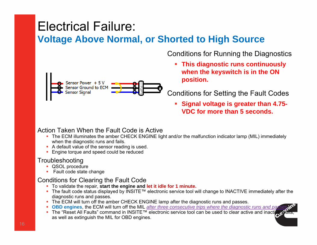
Electrical Failure: Voltage Above Normal, or Shorted to High Source
16
Conditions for Running the Diagnostics This diagnostic runs continuously
when the keyswitch is in the ON position.
Conditions for Setting the Fault Codes Signal voltage is greater than 4.75-
VDC for more than 5 seconds.
Action Taken When the Fault Code is Active The ECM illuminates the amber CHECK ENGINE light and/or the malfunction indicator lamp (MIL) immediately
when the diagnostic runs and fails. A default value of the sensor reading is used. Engine torque and speed could be reduced
Troubleshooting QSOL procedure Fault code state change
Conditions for Clearing the Fault Code To validate the repair, start the engine and let it idle for 1 minute. The fault code status displayed by INSITE™ electronic service tool will change to INACTIVE immediately after the
diagnostic runs and passes. The ECM will turn off the amber CHECK ENGINE lamp after the diagnostic runs and passes. OBD engines, the ECM will turn off the MIL after three consecutive trips where the diagnostic runs and passes. The “Reset All Faults” command in INSITE™ electronic service tool can be used to clear active and inactive faults,
as well as extinguish the MIL for OBD engines.

Electrical Failure: Voltage Below normal, or Shorted to Low Source
17
Conditions for Running the Diagnostics This diagnostic runs continuously
when the keyswitch is in the ON position.
Conditions for Setting the Fault Codes Signal voltage is Less than 0.25-VDC
for more than 5 seconds.
Action Taken When the Fault Code is Active The ECM illuminates the amber CHECK ENGINE light and/or the malfunction indicator lamp (MIL) immediately
when the diagnostic runs and fails. A default value of the sensor reading is used. Engine torque and speed could be reduced
Troubleshooting QSOL procedure Fault code state change
Conditions for Clearing the Fault Code To validate the repair, start the engine and let it idle for 1 minute. The fault code status displayed by INSITE™ electronic service tool will change to INACTIVE immediately after the
diagnostic runs and passes. The ECM will turn off the amber CHECK ENGINE lamp after the diagnostic runs and passes. OBD engines, the ECM will turn off the MIL after three consecutive trips where the diagnostic runs and passes. The “Reset All Faults” command in INSITE™ electronic service tool can be used to clear active and inactive faults,
as well as extinguish the MIL for OBD engines.

Electrical Failure:Current above normal or grounded circuit
18
Conditions for Running the Diagnostics This diagnostic runs continuously
when the engine is running.
Conditions for Setting the Fault Codes The electronic control module (ECM)
detects a short circuit to ground in the EGR motor supply circuits.
EGR Valve Control Circuit (Only on Midrange)Action Taken When the Fault Code is Active
The ECM illuminates the amber CHECK ENGINE lamp and/or the malfunction indicator lamp (MIL) immediately when the diagnostic runs and fails.
Active and stationary regeneration of the diesel particulate filter will be disabled. The EGR valve will be closed. Engine torque will be reduced if the engine is operated for an extended period of time with this fault active.
Conditions for Clearing the Fault Code The fault code will always be inactive at key ON. To validate the repair, start and idle the engine for 1
minute. If the fault code does not become active again, the repair has been validated. The fault code status displayed by INSITE™ electronic service tool will change to INACTIVE immediately after the
diagnostic runs and passes. The ECM will turn off the amber CHECK ENGINE lamp after the diagnostic runs and passes. For On-Board Diagnostics (OBD) engines, the ECM will turn off the malfunction indicator lamp (MIL) after three
consecutive trips where the diagnostic runs and passes. The “Reset All Faults” command in INSITE™ electronic service tool can be used to clear active and inactive faults,
as well as extinguish the MIL for OBD applications

Electrical Failure:Current Below normal or Open circuit
19
Conditions for Running the Diagnostics This diagnostic runs continuously
when the engine is running.
Conditions for Setting the Fault Codes The electronic control module (ECM)
detects an open circuits.
Action Taken When the Fault Code is Active The electronic control module (ECM) illuminates the amber CHECK ENGINE lamp and/or the
malfunction indicator lamp (MIL) immediately when the diagnostic runs and fails. Engine torque and speed could be reduced
Conditions for Clearing the Fault Code To validate the repair, perform a key cycle, and then start the engine and let it idle for 1 minute. The fault code status displayed by the INSITE™ electronic service tool will change to INACTIVE
immediately after the diagnostic runs and passes. The ECM will turn off the amber CHECK ENGINE lamp after the diagnostic runs and passes. For OBD engines, the ECM will turn off the MIL after 3 consecutive trips where the diagnostic runs
and passes. The “Reset All Faults” command in the INSITE™ electronic service tool can be used to clear active
and inactive faults, as well as extinguish the MIL for OBD applications

Mechanical Failure:Data erratic, intermittent or incorrectConditions for Running the Diagnostics This diagnostic runs continuously when the keyswitch is in the ON position.
This diagnostic runs when engine condition present.
Conditions for Setting the Fault Codes Signal is erratic, intermittent or incorrect
‒ Missing tooth on speed sensor, higher than achievable speed reading
‒ Sensor reading does not match the engine operating conditions (high or low)‒ Sensor is reading an erratic value‒ Reading is not changing with the engine operating conditions
20

CM2350 Controls – Adaptive Trim Function for the Injectors
For most injectors previously used on Cummins XPI fuel systems injector trim codes (bar codes) were required.With CM2350 control system there is no requirement to record and program injector trim code. ECM has new function to monitor injector performance and compliance with EPA tail pipe exhaust emissions regulations.How it works? During engine motoring events*, Engine motoring event - When you do a throttle snap in the shop or when
you are at some road speed and quickly back off the throttle. It only adapts during a motoring event which is no commanded fuel but engine is above idle. Event of any rapid engine speed non-braking deceleration. ECM changes injector injection parameters, Records change of emissions and performance, ECM compares recorded data against pre-programmed parameters , If there is discrepancy found, adjustments are made to injector timing and
duration to comply with performance and emissions requirements.
21
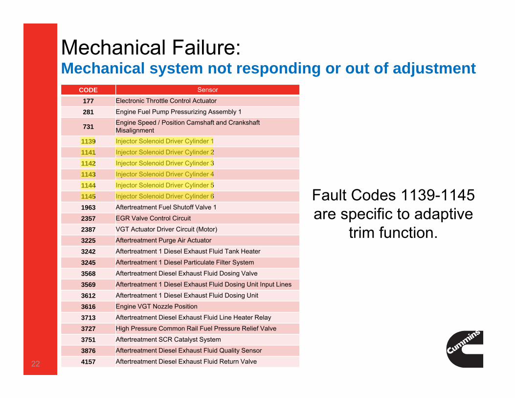
Mechanical Failure:Mechanical system not responding or out of adjustment
22
Fault Codes 1139-1145 are specific to adaptive
trim function.
CODE Sensor
177 Electronic Throttle Control Actuator
281 Engine Fuel Pump Pressurizing Assembly 1
731 Engine Speed / Position Camshaft and Crankshaft Misalignment
1139 Injector Solenoid Driver Cylinder 1
1141 Injector Solenoid Driver Cylinder 2
1142 Injector Solenoid Driver Cylinder 3
1143 Injector Solenoid Driver Cylinder 4
1144 Injector Solenoid Driver Cylinder 5
1145 Injector Solenoid Driver Cylinder 6
1963 Aftertreatment Fuel Shutoff Valve 1
2357 EGR Valve Control Circuit
2387 VGT Actuator Driver Circuit (Motor)
3225 Aftertreatment Purge Air Actuator
3242 Aftertreatment 1 Diesel Exhaust Fluid Tank Heater
3245 Aftertreatment 1 Diesel Particulate Filter System
3568 Aftertreatment Diesel Exhaust Fluid Dosing Valve
3569 Aftertreatment 1 Diesel Exhaust Fluid Dosing Unit Input Lines
3612 Aftertreatment 1 Diesel Exhaust Fluid Dosing Unit
3616 Engine VGT Nozzle Position
3713 Aftertreatment Diesel Exhaust Fluid Line Heater Relay
3727 High Pressure Common Rail Fuel Pressure Relief Valve
3751 Aftertreatment SCR Catalyst System
3876 Aftertreatment Diesel Exhaust Fluid Quality Sensor
4157 Aftertreatment Diesel Exhaust Fluid Return Valve

Mechanical Failure:Abnormal rate of change
Code Component Caused
3145 Aftertreatment 1 SCR Intake Temperature Sensor The ECM detects that the SCR catalyst intake temperature is not changing to match engine operating conditions.
3149 Aftertreatment 1 SCR Outlet Temperature Sensor The ECM detects that the SCR catalyst outlet temperature is not changing to match engine operating conditions.
3361 Intake Manifold 1 Pressure The ECM detects that the SCR catalyst outlet temperature is not changing to match engine operating conditions.
3389 Engine Exhaust Gas Recirculation (EGR) System The measured EGR flow does not meet the commanded EGR flow for 30 seconds.
3492 Real Time Clock The real time clock indicates a stuck engine off timer.The engine off timer is not counting correctly and does not match other timers in the ECM.
3583 Aftertreatment Outlet NOx Sensor Heater The ECM detects that the NOx sensor heater is unable to maintain its normal operating temperature.
3649 Aftertreatment 1 Intake NOx Sensor Heater The ECM detects that the NOx sensor heater is unable to maintain its normal operating temperature.
3725 Aftertreatment 1 Intake NOx Sensor The aftertreatment intake NOx sensor reading is not valid.
3912 Aftertreatment 1 Outlet NH3 Gas Sensor Heater The aftertreatment intake NH3 sensor reading is not valid.
3937 Aftertreatment 1 Intermediate NH3 Gas Sensor The ECM detects that the Intermediate NH3 Gas reading is not changing to match engine operating conditions.
23

Abnormal rate of change
Reading 1 Reading 2 Expected Reading
24

ECM Logical Faults
• Data not Rational• Data erratic, intermittent or incorrect (also could be
Mechanical failure)• Data Valid But Above Normal Operating Range‒ Least Severe Level‒ Moderately Severe Level‒ Most Severe Level
• Data Valid But Below Normal Operating Range‒ Least Severe Level‒ Moderately Severe Level‒ Most Severe Level
• Condition Exists• Out of Calibration
25
Sensor Reading Range
26
LowLimit
Min
Max
HighLimitOut-of-Range High
Out-of-Range Low
Data Valid But Above Normal Operating Range
Data Valid But Below Normal Operating Range
ExpectedRange
Data Erratic
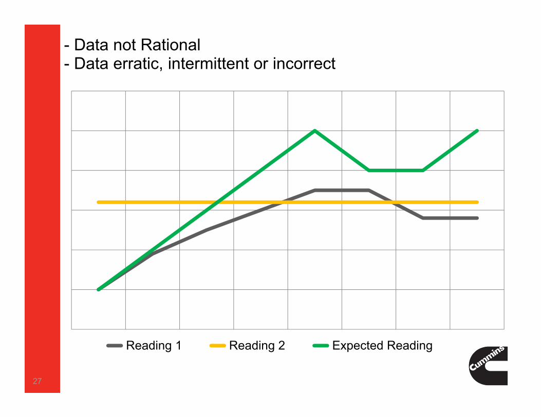
- Data not Rational- Data erratic, intermittent or incorrect
Reading 1 Reading 2 Expected Reading
27

ECM INPUTS
28
29
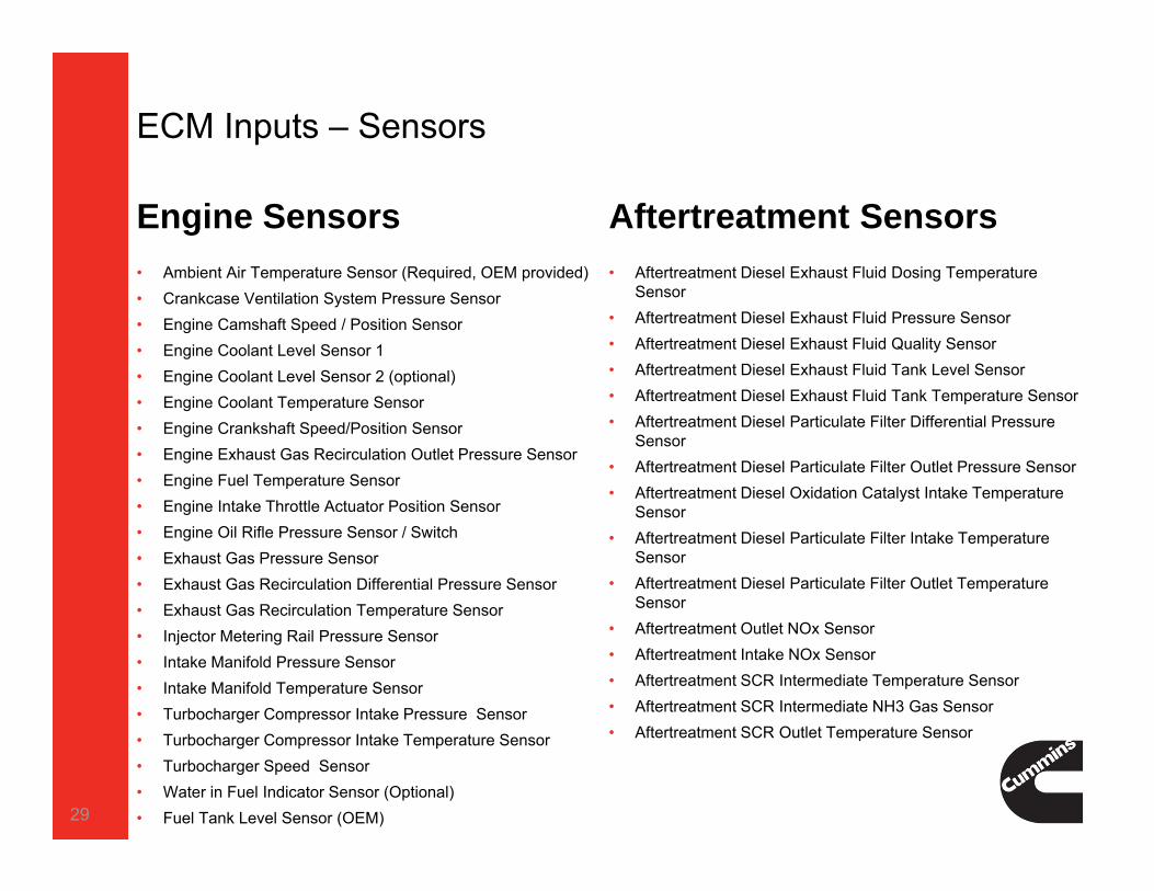
ECM Inputs – Sensors
Engine Sensors• Ambient Air Temperature Sensor (Required, OEM provided)• Crankcase Ventilation System Pressure Sensor• Engine Camshaft Speed / Position Sensor • Engine Coolant Level Sensor 1 • Engine Coolant Level Sensor 2 (optional)• Engine Coolant Temperature Sensor • Engine Crankshaft Speed/Position Sensor • Engine Exhaust Gas Recirculation Outlet Pressure Sensor • Engine Fuel Temperature Sensor • Engine Intake Throttle Actuator Position Sensor • Engine Oil Rifle Pressure Sensor / Switch • Exhaust Gas Pressure Sensor • Exhaust Gas Recirculation Differential Pressure Sensor • Exhaust Gas Recirculation Temperature Sensor• Injector Metering Rail Pressure Sensor • Intake Manifold Pressure Sensor • Intake Manifold Temperature Sensor • Turbocharger Compressor Intake Pressure Sensor • Turbocharger Compressor Intake Temperature Sensor • Turbocharger Speed Sensor • Water in Fuel Indicator Sensor (Optional)• Fuel Tank Level Sensor (OEM)
Aftertreatment Sensors• Aftertreatment Diesel Exhaust Fluid Dosing Temperature
Sensor• Aftertreatment Diesel Exhaust Fluid Pressure Sensor• Aftertreatment Diesel Exhaust Fluid Quality Sensor • Aftertreatment Diesel Exhaust Fluid Tank Level Sensor • Aftertreatment Diesel Exhaust Fluid Tank Temperature Sensor• Aftertreatment Diesel Particulate Filter Differential Pressure
Sensor• Aftertreatment Diesel Particulate Filter Outlet Pressure Sensor• Aftertreatment Diesel Oxidation Catalyst Intake Temperature
Sensor • Aftertreatment Diesel Particulate Filter Intake Temperature
Sensor • Aftertreatment Diesel Particulate Filter Outlet Temperature
Sensor• Aftertreatment Outlet NOx Sensor • Aftertreatment Intake NOx Sensor • Aftertreatment SCR Intermediate Temperature Sensor• Aftertreatment SCR Intermediate NH3 Gas Sensor • Aftertreatment SCR Outlet Temperature Sensor
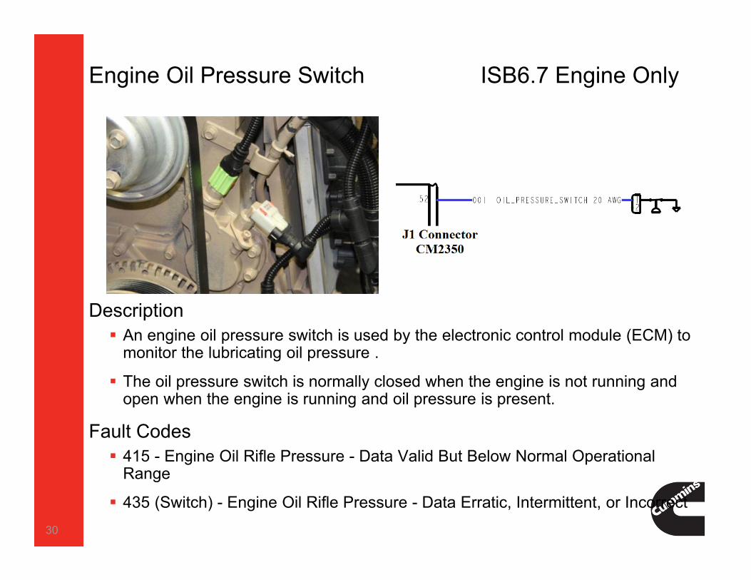
Engine Oil Pressure Switch ISB6.7 Engine Only
30
Description An engine oil pressure switch is used by the electronic control module (ECM) to
monitor the lubricating oil pressure .
The oil pressure switch is normally closed when the engine is not running and open when the engine is running and oil pressure is present.
Fault Codes 415 - Engine Oil Rifle Pressure - Data Valid But Below Normal Operational
Range
435 (Switch) - Engine Oil Rifle Pressure - Data Erratic, Intermittent, or Incorrect
415 - Engine Oil Rifle Pressure – SwitchData Valid But Below Normal Operational Range - Most Severe Level
Conditions for Running the Diagnostics This diagnostic runs continuously when the engine is running.
Conditions for Setting the Fault Codes The ECM detects that the engine oil pressure is below minimum operating limits.
Action Taken When the Fault Code is Active The ECM illuminates the red STOP ENGINE lamp immediately when the diagnostic
runs and fails. A torque derate is issued by the ECM, limiting the power output of the engine .
Conditions for Clearing the Fault Code To validate the repair, start the engine and let it idle for 1 minute. The fault code status displayed by INSITE™ electronic service tool will change to
INACTIVE immediately after the oil pressure reading is detected to be within the normal operating limits and the diagnostic runs and passes.
The ECM will turn off the red STOP ENGINE lamp after the diagnostic runs and passes.
The Reset All Faults command in INSITE™ electronic service tool can be used to clear active and inactive faults.
31
435 - Engine Oil Rifle Pressure – SwitchData Erratic, Intermittent, or Incorrect
Conditions for Running the Diagnostics This diagnostic runs when the keyswitch is turned ON and before engine speed is
detected. The diagnostic only runs once per trip.
Conditions for Setting the Fault Codes The ECM detects that the engine oil pressure switch is indicating that oil
pressure is present (switch is open) at initial key ON for two consecutive key cycles, when the ECM expected to see no oil pressure (switch closed) at key ON.
Action Taken When the Fault Code is Active The ECM illuminates the amber CHECK ENGINE lamp and/or Malfunction Indicator
Lamp (MIL) immediately when the diagnostic runs and fails A default value for the engine oil pressure reading is used.
Conditions for Clearing the Fault Code To validate the repair, perform a key cycle. Turn the key to the ON position but do not start the engine .
The fault code status displayed by INSITE™ electronic service tool will change to INACTIVE immediately after the diagnostic runs and passes.
The ECM will turn off the amber CHECK ENGINE lamp after the diagnostic runs and passes.
For On-Board Diagnostic (OBD) engines, the ECM will turn off the MIL after 3 ( three ) consecutive trips where the diagnostic runs and passes.
The Reset All Faults command in INSITE™ electronic service tool can be used to clear active and inactive faults, as well as extinguish the MIL for OBD applications.
32

Turbocharger Compressor Intake Pressure Sensor
33
The turbocharger compressor intake temperature sensor is a variable resistor sensor and is used to measure the temperature of the air entering the compressor intake of the turbocharger . The electronic control module (ECM) supplies 5-VDC to the compressor intake temperature signal circuit. This sensor signal voltage changes, based on the pressure in the intake manifold. Component Location Most engines use a combination ambient air pressure /temperature sensor located in the OEM intake air
plumbing.
Fault Codes: 122 - Voltage above normal, or shorted to high source
123 - Voltage below normal, or shorted to low source
124 - Data Valid But Above Normal Operating Range - Moderately Severe Level – High Pressure
125 - Data Valid But Below Normal Operating Range - Moderately Severe Level – Low Pressure

124 - Intake Manifold 1 Pressure – Data Valid But ABOVENormal Operating Range - Moderately Severe LevelConditions for Running the Diagnostics This diagnostic runs continuously when the engine is running.
Conditions for Setting the Fault Codes The ECM detects that the VGT actuator is slow to meet commanded position. Intake manifold pressure is above the maximum operating limit.
Action Taken When the Fault Code is Active The ECM illuminates the amber CHECK ENGINE lamp immediately when the
diagnostic runs and fails.
Conditions for Clearing the Fault Code To validate the repair, start the engine and let it idle for 5 minutes. For On-Board Diagnostics (OBD) engines, the ECM will turn off the MIL after three
consecutive trips where the diagnostic runs and passes.
34
125 - Intake Manifold 1 Pressure – Data Valid But BELOWNormal Operating Range - Moderately Severe LevelConditions for Running the Diagnostics This diagnostic runs continuously when the engine is running.
Conditions for Setting the Fault Codes The ECM detects that the intake manifold pressure signal reading is below the
expected level for the present engine operating conditions. Intake manifold pressure is below the minimum operating limit.
Action Taken When the Fault Code is Active The ECM illuminates the amber CHECK ENGINE lamp and/or the malfunction
indicator lamp (MIL) immediately when the diagnostic runs and fails.
Conditions for Clearing the Fault Code The fault code status displayed by INSITE™ electronic service tool will change to
INACTIVE after the engine is able to achieve the desired oxygen level necessary for complete combustion and the diagnostic runs and passes.
For on-board diagnostics (OBD) engines, the ECM will turn off the MIL after three consecutive trips where the diagnostic runs and passes.
35
Turbocharger Compressor Intake Temperature Sensor
36
The intake manifold 1 temperature sensor is a variable resistor sensor and is used to measure the temperature of the air entering the intake manifold of the engine. The engine intake manifold temperature value is used by the electronic control module (ECM) for the engine protection system and engine emissions control. The ECM supplies 5 volts to the intake manifold temperature signal circuit, and monitors the change in voltage caused by changes in the resistance of the sensor to determine the intake manifold temperature.
Low Temperature – High Resistance – High Voltage at ECM
High Temperature – Low Resistance – Low Voltage at ECM
Component Location The intake manifold air temperature sensor is located in the air intake manifold.
Fault Codes 153 - Voltage above normal, or shorted to high source
154 - Voltage below normal, or shorted to low source
155 - Data valid but above normal operational range - Most Severe Level - High Temperature
155 - Intake Manifold 1 Temperature - Data Valid But Above Normal Operational Range - Most Severe LevelConditions for Running the Diagnostics This diagnostic runs continuously when the keyswitch is in the ON
position.Conditions for Setting the Fault Codes Intake manifold air temperature reading is greater than 132°C [270°F] for
5 sec.Action Taken When the Fault Code is Active The ECM illuminates the red STOP ENGINE light immediately when the
diagnostic runs and fails. The torque output of the engine will be reduced. Maximum engine operating speed will be decreased. The engine will be shut off if the Engine Protection Shutdown feature is
enabled.Conditions for Clearing the Fault Code To validate the repair, start the engine and let it idle for 1 minute. The fault code status displayed by the INSITE™ electronic service tool
will change to INACTIVE immediately after the diagnostic runs and passes. The ECM will turn off the red STOP ENGINE lamp after the diagnostic
runs and passes. 37

ECM Inputs - Sensors - OEM Provided
Accelerator Position Sensor Dual Analog
PWM
Ambient Air Temperature Sensor Engine Coolant Level Sensor 1 & 2Fan Speed Sensor Magnetic Pickup VSS Remote Accelerator Position SensorWater in Fuel Sensor DEF Tank Temperature Sensor DEF Tank Level Sensor Fuel Tank Level Sensor
38
ECM Inputs - Switches - OEM Provided
Accelerator Interlock Switch/ Torque Limit Switch Air Conditioner Pressure Switch Air Shutoff Valve Manual Switch Air Shutoff Valve Test Switch CC/PTO On/Off Switch CC/PTO Set/Resume Switch Clutch Switch Diagnostics On/Off Switch/ Diesel Particulate Filter Regeneration Force SwitchRegeneration Inhibit Switch Engine Brake On/Off Switch (VGT Brake) 3-Position Engine Brake Level Switch (Compression Brake) Engine Protection
Shutdown Override Switch Multiplexed Accelerator Error Limp Home Switch Fan Control Switch Governor Type Switch/ Switched Max Engine Speed/Switched RSG OEM Switched Engine Protection Shutdown Switch Parking Brake Switch PTO Additional Switch Rear Axle Ratio Switch Remote Accelerator On/Off Switch Remote PTO On/Off Switch Service Brake Pedal Position SwitchService Brake Validation Switch
39
ECM Outputs - Lamps and Gauges- OEM Provided
Amber Warning Lamp Air Shutoff Valve Lamp Diesel Exhaust Fluid Lamp Diesel Exhaust Fluid Level Gauge Diesel Particulate Filter Lamp High Exhaust System Temperature (HEST) Lamp Malfunction Indicator Lamp (MIL) Stop Lamp Wait To Start (WTS) Lamp
40

RELAYS / SOLENOIDS
41

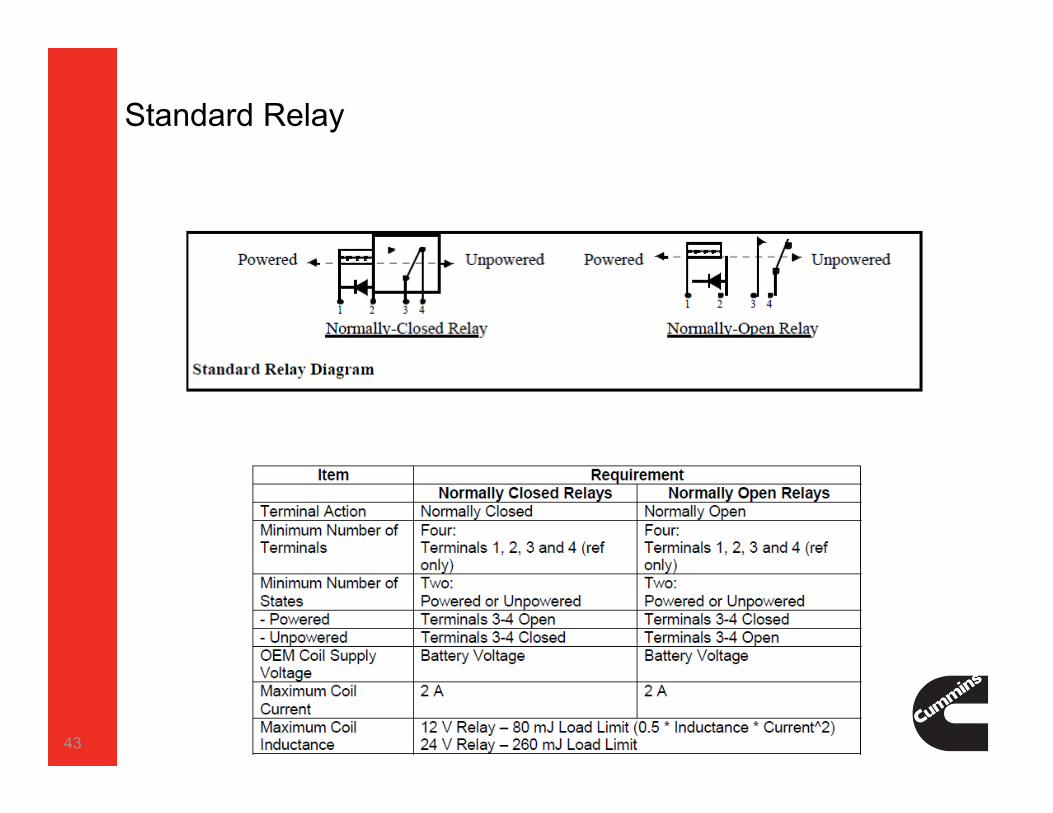
Standard Relay
The relays described in this section will function for many of the OEM supplied relays used with the CM2350 subsystem. Where a different relay is required (e.g. Intake Air Heaters), an example relay is supplied in the specific section.Operation Relays can operate in a Normally-Open or Normally-Closed fashion.
The Normally-Open or Normally-Closed refers to the condition of the relay terminals when power is not being supplied to the relay coil.
Hardware Any relay using the Standard Relay specification MUST meet the
specifications in the table below. This description uses terminal numbers on the relays for reference only; a particular relay may use a different numbering scheme. Cummins recommends using relays that contain an integral suppression diode.
42
Standard Relay
43
ECM Outputs - Relays/Solenoids - OEM Provided
Air Shut Off Valve / Idle Shutdown Relay
Brake Lamp Relay
Air Heater Relay (MR Only)
Fan Clutch Relay/Solenoid
Fuel Heater Relay
Starter Lockout Relay
DEF Line Heater Relay
DEF Line 4 (Dosing Unit) Heater Relay
DEF Coolant Flow Valve Solenoid
44
Air Shut Off Valve MR / HD
Overview The Air Shut Off Valve provides power to control the air flow to the
engine ASO device (Pneumatic System), when the ECM detects an engine over speed due to combustible gas in the environment in which the engine is operating.
OperationWhen the ASO solenoid valve is energized, the air flow coming from
the reservoir tank is directed to the ASO valve and triggers the ASO valve (Pneumatic System). When the solenoid valve is de-energized, the air is released from the ASO valve.
Hardware Cummins recommends a 3-way solenoid valve to be used for the
ASO valve control.
Note: ASO solenoid drive signal is mutually exclusive with the Idle Shutdown Relay signal.
45
Idle Shutdown Relay
Overview The Idle Shutdown relay disconnects power from selected highcurrent
vehicle systems when the Idle Shutdown feature shuts down the engine. The Idle Shutdown feature turns off the engine and energizes the Idle Shutdown Relay after a programmable time period of engine idling without interruption has been exceeded.
Operation When the relay is energized; the terminals OPEN and disconnect power
from high current devices. When the relay is not energized, the terminals are CLOSED, allowing power to high current devices.
Hardware The Idle Shutdown Relay MUST meet the specifications for a Normally-
Closed Standard Relay as described in the Standard Relay section below.
Note: Idle Shutdown Relay signal is mutually exclusive with the ASO solenoid drive signal.
46

Air Shut Off Valve
47
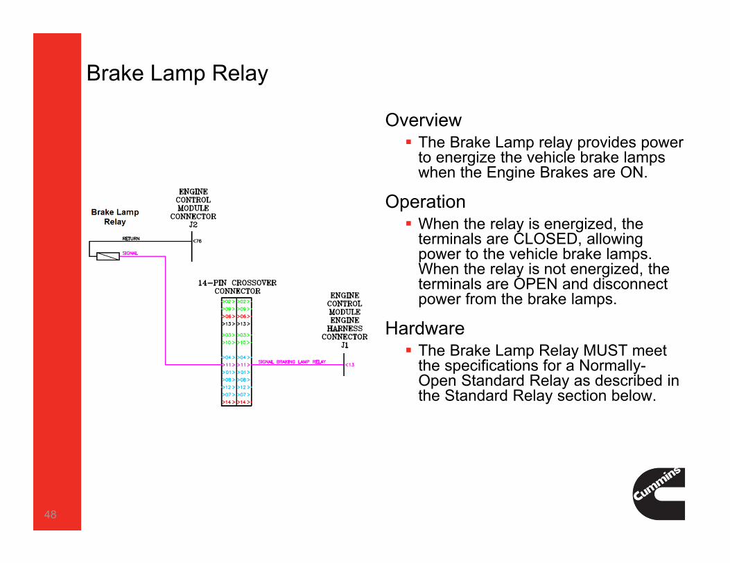
Brake Lamp Relay
Overview The Brake Lamp relay provides power
to energize the vehicle brake lamps when the Engine Brakes are ON.
Operation When the relay is energized, the
terminals are CLOSED, allowing power to the vehicle brake lamps. When the relay is not energized, the terminals are OPEN and disconnect power from the brake lamps.
Hardware The Brake Lamp Relay MUST meet
the specifications for a Normally-Open Standard Relay as described in the Standard Relay section below.
48

Intake Air Heater Relay (ISB6.7 and ISL9 Only)
The ECM uses the Intake Air Heater Relay to energize the Intake Air Heater during cold ambient temperatures. OEM MUST have a relay installed for all 2013 ISB6.7 and ISL9 engines.Operation During cold ambient temperatures the ECM uses the relay to energize
the intake air heater prior to and following the starting of the engine. The ECM will de-energize the relays during engine cranking.
Hardware Any Intake Air Heater Relay MUST match the specifications from the
table below. The relay contacts SHOULD support the nominal continuous and in rush current draws requirements. The wiring SHOULD also be protected with an adequately sized fuse or circuit breaker that can accommodate the current draw characteristics of the Intake Air Heater Element.
49

Fan Clutch Relay/Solenoid
Overview The Fan Clutch Relay/Solenoid controls engagement of the fan drive.
There are various types of fan drive control components some operate in an On/Off fashion typically by controlling electrical power (Relay) or compressed air (Solenoid) to the fan clutch.
Operation The Fan Clutch Relay/Solenoid may operate in a Normally Open or
Normally Closed condition. Without full knowledge of the vehicle setup, it cannot be specified whether this Relay/Solenoid should be Normally Open or Normally Closed.
Recommended practice would be for the fan to be fully engaged for an open circuit condition. The ECM signal to turn the Fan ON may be programmed as a high or low voltage signal
50
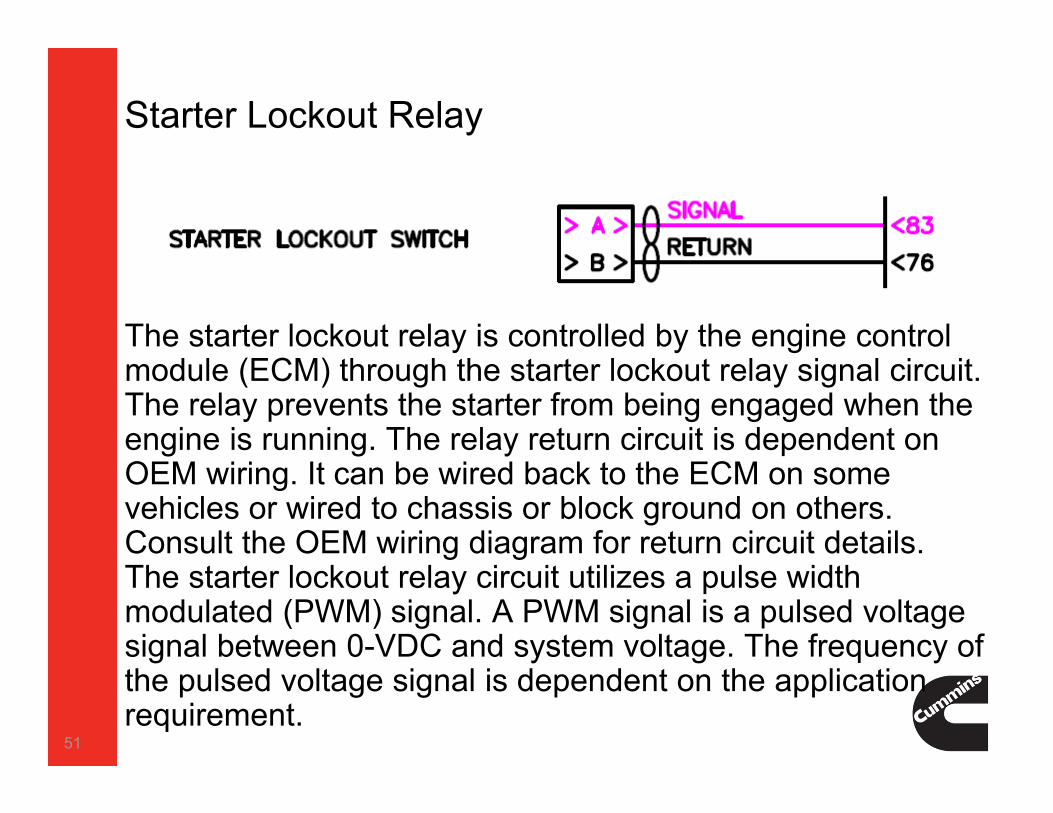
Starter Lockout Relay
The starter lockout relay is controlled by the engine control module (ECM) through the starter lockout relay signal circuit. The relay prevents the starter from being engaged when the engine is running. The relay return circuit is dependent on OEM wiring. It can be wired back to the ECM on some vehicles or wired to chassis or block ground on others. Consult the OEM wiring diagram for return circuit details. The starter lockout relay circuit utilizes a pulse width modulated (PWM) signal. A PWM signal is a pulsed voltage signal between 0-VDC and system voltage. The frequency of the pulsed voltage signal is dependent on the application requirement.
51

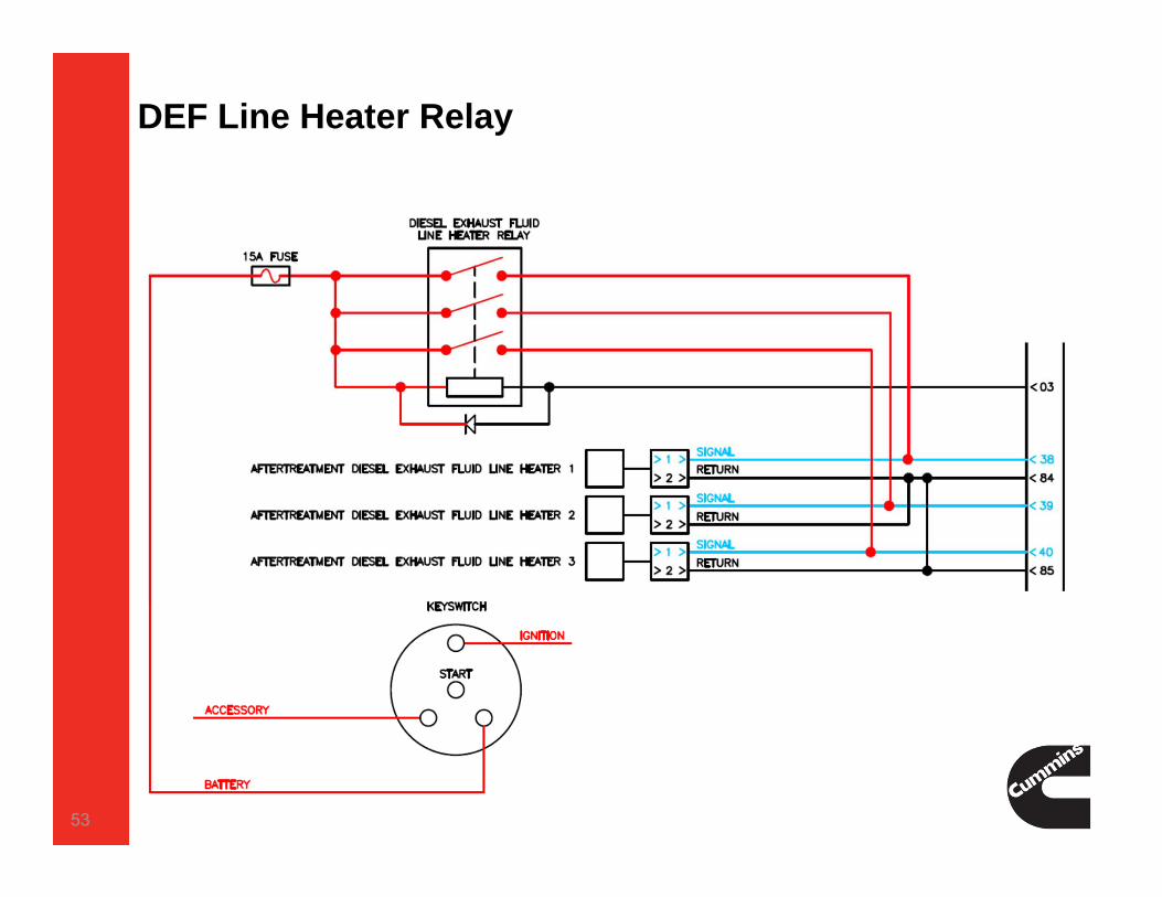
DEF Line Heater Relay
Overview The DEF Line Heater relay is controlled by the Engine Control Module
(ECM). OEM MUST power all three DEF line (Pressure, Suction and Throttle lines) heating equipment to ensure vehicle acceptance for all seasons.
Operation When the DEF Line Heater relay is energized by the ECM, the DEF line
heaters are powered up by the battery voltage. When the relay is de-energized, the power to the line heaters is cut off.
Hardware The line heaters are controlled by a single high side relay (single relay
with diode line isolation, single 3-pole relay, or three separate relays if desired), all lines ON or all lines OFF. The DEF line heater relay MUST meet an expected life of 2 million operation cycles at rated current. Each line heater circuit MUST be separated when the relay is open to
allow individual line diagnostics to complete. Line heater return MUST be through the ECM also to support line heater diagnostics.
52
DEF Line Heater Relay
53
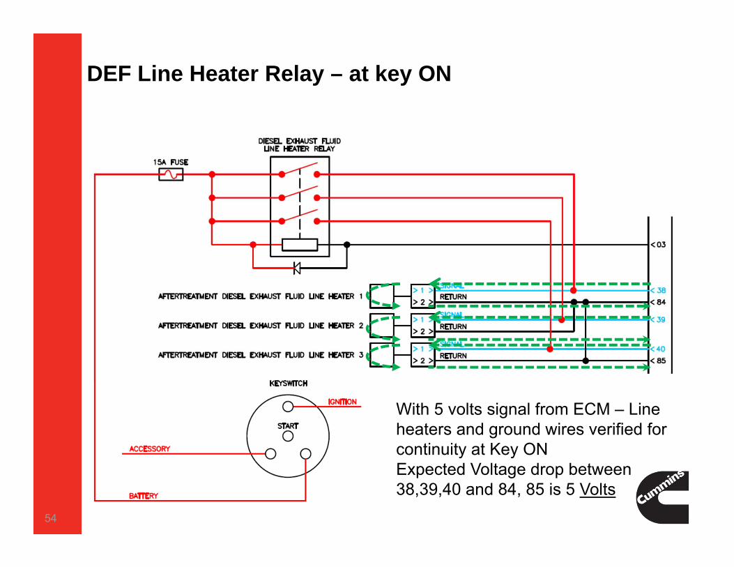
DEF Line Heater Relay – at key ON
54
With 5 volts signal from ECM – Line heaters and ground wires verified for continuity at Key ONExpected Voltage drop between 38,39,40 and 84, 85 is 5 Volts

DEF Line Heater Relay – Relay energized
55
At Line heaters ONECM monitors voltage drop between 38,39,40 and 84,85, 03Expected drop Battery Voltage
3425
3261
3258
3562

DEF Supply Module Heater Relay
Overview The DEF Supply Module Heater relay is controlled by the Engine
Control Module (ECM). OEM MUST power the DEF Supply Module Heater equipment to ensure vehicle acceptance for all seasons.
OperationWhen the DEF Supply Module Heater relay is energized by the ECM,
the DEF Supply Module heater is powered up by the battery voltage. When the relay is de-energized, the power to the heater is cut off.
Hardware The DEF Supply Module Heater relay MUST be a normally open
standard relay.
56

DEF Supply Module Heater Relay
57

DEF Coolant Flow Valve
Overview The DEF Coolant Flow Valve is controlled by the Engine Control Module
(ECM). OEM MUST supply and connect the DEF Coolant Flow Valve and plumbing equipment to ensure vehicle acceptance for all seasons.
Operation When the DEF Coolant Flow Valve is energized by the ECM, coolant is
allowed to flow to the DEF Tank for proper DEF tank heating. When the valve is de-energized, the coolant flow is cut off. Valve Action - Is Normally Closed.
Hardware It is recommended that the valve sourced incorporates coil suppression.
58

CM2350 ControlsINTERNAL FUNCTION AND ECM SERVICE TESTS
59

INSITE, ECM Diagnostic Tests1 Aftertreatment Diesel Exhaust Fluid System Leak Test Aftertreatment
2 Aftertreatment Diesel Particulate Filter Regeneration Aftertreatment
3 Cylinder Cutout Fuel system
4 Cylinder Performance Test Fuel system
5 Diesel Exhaust Fluid Doser Pump Override Test Aftertreatment
6 Diesel Exhaust Fluid Doser System Heater Test Aftertreatment
7 Engine State Monitor Controls
8 Fan Override Test Controls
9 Fast Idle Warm-Up Test Controls
10 Fuel System Leakage Test Fuel system
11 Fuel Lift Pump Override Test (ISL only) Fuel system
12 Intake Air Heater Override Controls
13 SAE J1939 Datalink Control Test Controls
14 Setup for Dynamometer Controls
15 Switch and Sensor Intermittent Connection Test Controls
16 Starter Lockout Relay Driver Override Test Controls
17 VGT Electronic Actuator Installation and Calibration Air Intake and Exhaust
18 SCR PERFORMANCE TEST Aftertreatment
19 INJECTOR PERFORMANCE TEST (XPI FUEL SYSTEMS) Fuel system
20 ADAPTIVE TRIM Fuel system60
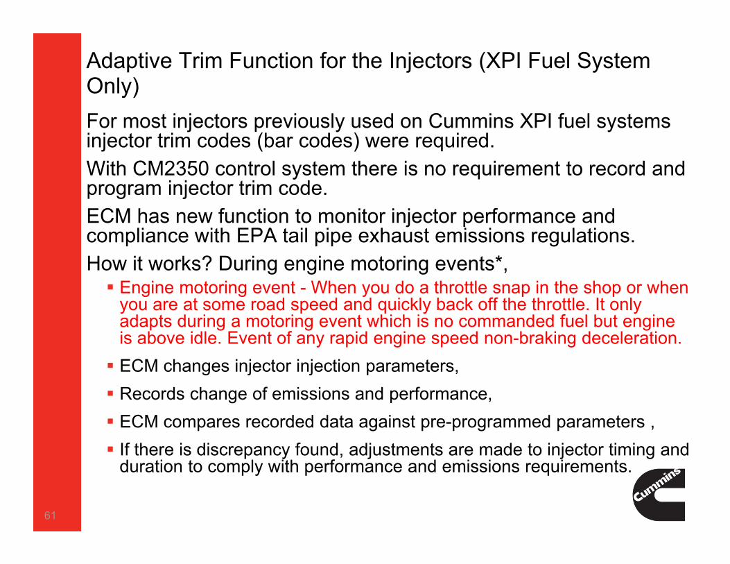
Adaptive Trim Function for the Injectors (XPI Fuel System Only)For most injectors previously used on Cummins XPI fuel systems injector trim codes (bar codes) were required.With CM2350 control system there is no requirement to record and program injector trim code. ECM has new function to monitor injector performance and compliance with EPA tail pipe exhaust emissions regulations.How it works? During engine motoring events*, Engine motoring event - When you do a throttle snap in the shop or when
you are at some road speed and quickly back off the throttle. It only adapts during a motoring event which is no commanded fuel but engine is above idle. Event of any rapid engine speed non-braking deceleration. ECM changes injector injection parameters, Records change of emissions and performance, ECM compares recorded data against pre-programmed parameters , If there is discrepancy found, adjustments are made to injector timing and
duration to comply with performance and emissions requirements.
61
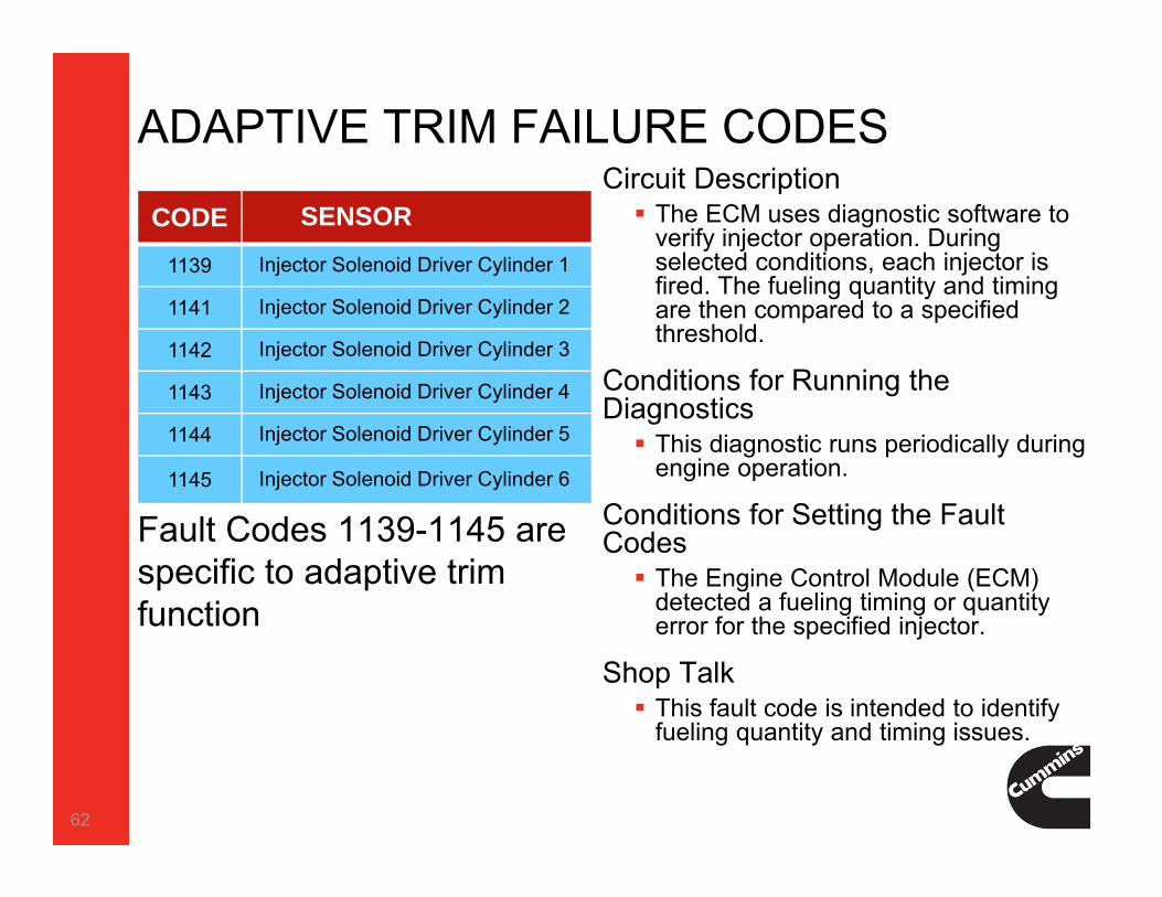
ADAPTIVE TRIM FAILURE CODES
CODE SENSOR
1139 Injector Solenoid Driver Cylinder 1
1141 Injector Solenoid Driver Cylinder 2
1142 Injector Solenoid Driver Cylinder 3
1143 Injector Solenoid Driver Cylinder 4
1144 Injector Solenoid Driver Cylinder 5
1145 Injector Solenoid Driver Cylinder 6
Fault Codes 1139-1145 are specific to adaptive trim function
Circuit Description The ECM uses diagnostic software to
verify injector operation. During selected conditions, each injector is fired. The fueling quantity and timing are then compared to a specified threshold.
Conditions for Running the Diagnostics This diagnostic runs periodically during
engine operation.
Conditions for Setting the Fault Codes The Engine Control Module (ECM)
detected a fueling timing or quantity error for the specified injector.
Shop Talk This fault code is intended to identify
fueling quantity and timing issues.
62

FUEL INJECTOR PERFORMANCE TEST
Fuel Injector Performance Test TSB120217
Similar to the Cut-Out Test or Cylinder Performance Test
Test will increase engine rpm to a specified value and then perform a number of engine decelerations
During engine decelerations, fuel pressure stability is verified, fuel pressure drop is monitored, fuel injectors are fired, and fuel injector operation is evaluated
At the conclusion of the test, the engine will return to idle and suspect fuel injectors will be identified as either a pass or fail
This test originally was released on July 16 2012 for production and service HD Engine serial number (ESN) first is
79598702
Engine is experiencing a performance issue that would require fuel injector diagnostics Black smoke
White smoke
Frequent regenerations
Rough running
Misfire
Fault Codes 3375 and 3376
Any time the cylinder cut-out test would be run
What's required to Run Test Requires latest calibrations
INSITE™ electronic service tool version 7.6.0 or later
63
FUEL INJECTOR PERFORMANCE TEST
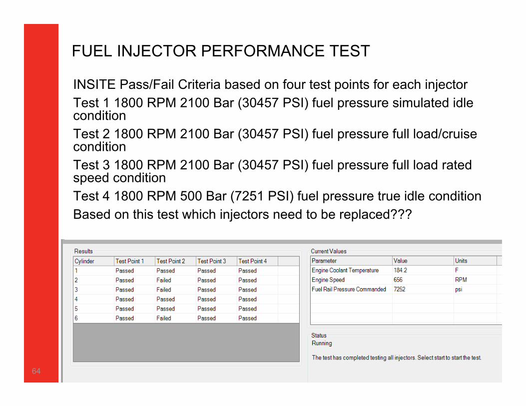
INSITE Pass/Fail Criteria based on four test points for each injectorTest 1 1800 RPM 2100 Bar (30457 PSI) fuel pressure simulated idle condition Test 2 1800 RPM 2100 Bar (30457 PSI) fuel pressure full load/cruise conditionTest 3 1800 RPM 2100 Bar (30457 PSI) fuel pressure full load rated speed conditionTest 4 1800 RPM 500 Bar (7251 PSI) fuel pressure true idle conditionBased on this test which injectors need to be replaced???
64

SHOP exercises
1. PERFORM NEW INSITE TESTS FOR BASE ENGINE
2. 96 WAY CONNECTOR EXERCISE
65

96 way connector Service
66

96 – Way Connector
67

68