electronic motor protection relays - ls.jktsiam.com fileelectronic motor protection relays gmp...
TRANSCRIPT


Electronic motor protection relays
GGMMPP SSeerriieess
DDMMPP SSeerriieess
IIMMPP SSeerriieess
EMPR is digital motor protection relay where the MCU(Microprocessor Control Unit) is built-in and featuresexcellent reliability by achieving real-time data processingand high precision.
EMPR

Contents
G3
Features G-3-6
Ordering G-3-9
Specification G-3-10
Characteristics G-3-14
Setting method G-3-24
Dimensions G-3-33
Wiring method G-3-39
Accessories G-3-42
Direct mounting EMPR new/old G-3-44
comparative table

replacing thermal overload relayis electronic motor protect relay which is usedto protect the low voltage motor and alsocalled as Electronic Overcurrent Relay or anElectronic Overload Relay.
As a digital motor protection relay with MCUEMPR is highly reliable by realization ofreal-time data processing and, retentionconfidentiality and also can secure motorsafely with various functions such as phaseloss, phase reverse, unbalanced, stall, lock,ground fault, short circuit protectiondepending on the model .
Compact and stylish appearance can becombined with the magnetic contactor andvarious installation methods make easydesign features and manufacture motorcontrol panel.
Especially, EMPR is EMC tested and approvedto operate safely without any malfunctioncaused by electromagnetic wave and surge.Most of the models have received CE Markand UL certification.
EMPR

EMP
R/D
MP
R
G3
General Motor Protection Relay
�Various connection & mount�Inverse or definite time mode�Ground fault type�Display the causes of the falut by LED
GMP Series
Digital Motor Protection Relay
�Ampere meter, Load rate and the causes of fault Display�Standard, Ground fault and short circuit protection type�Select the Inverse or definite time modes�Unit or Extension in one body by cable option�Option function type (DMP-a)
DMP Series
Intelligent Motor Protection Relay
�Wide current setting range (0.125~100A)�Communication support type�Zero current and residual current sensing�Save the fault events and operating time setup�Select the Inverse, thermal inverse or definite time modes�Unit or Extension in one body by option cable
IMP Series

G-3-6
Electronic motor protection relays FeaturesGMP Series
Direct mounton a contactor
Screw connection &Separate mount
Passing through CT holes &Separate mount
● Various protection functions
● Combination with Metasol contactors for compact motor starters
● Broad range of current setting ● Inverse time or definite time characteristics● Simple operation and trip cause indication via LED ● Various Connection
Types (GMP-�) 2P, 2T, 2S 3P, 3T, 3S 3PR, 3TR, 3SR 3TN, 3TZ 3TNR, 3TZR
Number of sensors 2CT 3CT
Overcurrent � � � � �
Phase failure � � � � �
Lock/Stall � � � � �
Phase unbalance � � � �
Reverse phase � �
Ground fault � �
EMPR model Contactor model
GMP22-2P/3P/3PR MC-9b, MC-12b, MC-18b, MC-22b
GMP40-2P/3P/3PR MC-32a, MC-40a
● Large current can be applied through additional current transformers ● MCU (Microprocessor Control Unit) built-in
- excellent reliability by achieving real-time data processing and high precision.
● Store of the last failure cause - can be checked by Test/Reset button 2 times.
● Products for ground fault protection - detecting of zero phase currents (ZCT used: GMP60-3TZ) - detecting of residual currents (ZCT unused: GMP60-3TN)
Certification of CE, UL, CCC and S mark
Currentsetting
LED indicator Trip time setting
Test / Reset button

FeaturesDMP Series
EMP
R/D
MP
R
G3● Various protection functions
G-3-7
● Applicable to inverter control circuit LS DMPR has high performance under the harmonic noise and can beused in the Inverter control circuit (20~200Hz)
● Optional functions (DMP-a type)- Storing up the last fault cause- Storing up motor operation hours
R phase current value S phase current value T phase current value
R
S
T
R
S
T
R
S
T
● Trip curve selectable (Inverse/Definite)
Inverse time characteristics Definite time characteristics
Protection DMP��-S/Sa DMP��-SZ/SZa DMP��-SI DMP��-T/Ta DMP��-TZ/TZa DMP��-TI
Wiring Screw type Tunnel type
Over current � � � � � �
Under current � � � � � �
Stall � � � � � �
Lock � � � � � �
Phase failure � � � � � �
Reverse phase � � � � � �
Phase unbalance � � � � � �
Ground fault � �
Short circuit � �
● Digital measuring and displaying - Display digital ampere-meter - Save the causes of the fault and the value- Display motor load rate by graph
● Convenient structure - Install the Unit / Extension type in one body
The display part may be separated from the bodyYou can check the values and the causes of thefault without opening the distribution panel door
- removable terminal block
R phase
S phase
T phase
Test/Reset button
FUNC button
Current knob
Digital display
Bar graph
Display button
Sel button
Time knob

G-3-8
Electronic motor protection relays FeaturesIMP Series
The EMPR IMP series are optimal solutions for protecting and monitoring motors incomplex industrial fields and provide high safety and productivity.
Wide Current Setting Range:
0.125~100A for One Model
With the slide S/W, the current setting range
can be decided 0.5~10A or 5~100A. According
to the CT penetration number, even 0.125A
current can be protected. (Wire penetration
hole).
Communication support type
RS-485 MODBUS communication with various
systems.The model with analogue signals
(4~20mA) is compatible with transducer
systems.
Thermal Inverse Time,
Inverse Time and Definite Time Modes
According to user’s needs, the motor can be
protected in the inverse time mode or definite
time mode.
Wide Ground Fault Sensitivity
30mA~25A
zero current sensing by zero sequence CT.
zero current sensing by Residual circuit.
Date and Total Operating Time Setup
When a fault occurs, its date and time are
stored for easy checkup. When the total
operation time is over, it is displayed for
changing motor bearings or supplying oil.
Quick Setup
All settings can be decided quickly on the
display.
Total Digital Motor Protection Relay with
the MCU (Microprocessor Control Unit)
Real-time processing and high precision
One-Body Type and Separate Body Type
The display can be attached to the panel front
so that current, operation time and settings can
be checked without fetching the unit. With the
display separated, the motor can be protected.
Applicable to Inverter Circuits
Thanks to its good high harmonic noise
characteristics, it can be applied to the of
inverter control circuits. The available
frequency range is 20~200Hz. When the
relative harmonic factor is over 30%, a
harmonic filter should be installed (However,
the ground fault function should be off).
Various Reset Functions
Manual, automatic and electric reset functions
are provided for customer convenience.
Password
Settings are protected with a password.
Storage of Fault Events
Up to five fault events can be stored for easy
fault history management.
3-Phase Digital Ampere-Meter
3-phase current is displayed every two
seconds for motor monitoring.
~100A
30mA 25A
MCU
INV
Save
Return

G-3-9
EMP
R/D
MP
R
G3
Ordering
2 R 1.5A 220 1a1b Sola
Model Type
-
Sol
Note) For GMP60-TD, GMP60-TDa 6/60A, GMP60-3TZ (R), 3TN (R), 3T (R)
GMP 22
GMP Series
DMP Series
IMP Series
DMP 06 S Z a 220 1a1b
IMP A420C
CT Type
2 2CT
3 3CT
Type
P Direct Coupling(Pin)
STerminal
Connection(Screw)
TPenetration
(Tunnel)
TE Economic
PDDirect Coupling(Definite Time)
TDCurrent Display(Definite Time)
TZ
TN
Reverse Phase
-Reverse ProtectionNo Protection
RReverse ProtectionProtection Available
AAutomatic Recovery
Nominal Current Current Setup Range (A)
1.5A 0.3~1.5
5A 1~5
22A 4.4~22
20A 4~20
40A 8~40
80A 16~80
06A 0.5~6
30A 3~30
60A 0.5~60Note)
Operation Current
110/220 AC 100~260V
24 AC 24V
48 AC 48V
110 AC 110V
220 AC 220V
380 AC 380 (440)V
Note) AC 24V, AC48V and AC380 (440)V are for GMP60T.
Aux. contactor
1c
1a1b
Note) When thepower isapplied, thesystem is inthe contactingstatus.
Frame Nominal Current Type
1.5A
22 5A
22A
4020A
40A
80 80A Terminal Connection
06A
60 30A Penetration
60A
Classification
- Existing Model
aOperation Time
Function
Ground Fault Protection (Zero-Phase- Sequence
Current Detection)Ground Fault Protection
(Residual CurrentDetection)
DirectCoupling,Terminal
Connection,Penetration Metasol
DirectCoupling
(Pin)
Note) 1. Even the same model has different contact specifications.2. When the power is applied, the system is in the contacting status.
Current Control Range
06 0.5~6A
36 3~36A
60 5~60A
Wiring
STerminal(Screw)
TPenetration(Tunnel)
Terminal(Screw)
Penetration(Tunnel)
OPTION
- Standard Model
ZGround Fault Protection
IShort circuitProtection
Classification
- Existing Model
a Operation TimeFunction
Control Voltage
220 AC 220V
110 AC 110V
Aux. contactor
1a1b
2a
2b
2a1b
Communication
NO None
A420 4~20mA Output
M485 MODBUS/RS-485
Items to be Protected
C Current
P

G-3-10
Electronic motor protection relays SpecificationGMP Series
Note) 1. When it is 2CT modle, only two-phase protection is available 2. The bracket for Din-rail mount is optional 3. When power applied Aux. contact operate
GMP22-2P/PD (1c)GMP22-3P/3PR
GMP22-2P(1a1b)
GMP22-2SGMP22-3S/3SR
GMP22-2TGMP22-3T/3TR
Ratings
Model
Type Pin type Screw type Tunnel type
No. of CT 2CT 2CT 3CT 2CT 3CT 2CT 3CT
Protection Overcurrent ● ● ● ● ● ● ●
Phase failure Note1) ● ● ● ● ● ● ●
Lock/Stall ● ● ● ● ● ● ●
Phase unbalance — — ● — ● — ●
Reverse phase — — ●(3PR) — ●(3SR) — ●(3TR)
Current setting range (A) 0.3~1.5, 1~5, 4.4~22
Operating time characteristics Inverse time (GMP22-2PD: Definite time)
Time setting Inverse time 0~30 sec
(sec) Definite D-time 0.2~60 sec for GMP22-2PD
O-time 5sec (Fixed) for GMP22-2PD
Reset-time Manual reset
Tolerance Current ±5%
Time ±5%(or±0.5sec)
Control power Voltage AC 110V/220V(±10%) AC 100~260V
Frequency 50/60Hz
Aux. contact Contact Note 3) 1SPDT (1c) 2SPST (1a1b)
Ratings 5A/250VAC Resistive load 3A/250VAC Resistive load
Operate (95 96 Close) (95 96 Close) (97 98 Open)
Insulation resistance Min 100㏁ at 500Vdc
Surge endurance (IEC 61000-4-5) 5kV Apply the standard wave
Fast transient burst (IEC 61000-4-4) 2kV
Environment Operation -25~70℃
Temperature Storage -30~80℃
Relative humidity 30~90%RH(No freezing)
Trip indicator Red LED Red/Green LED Red LED Red/Green LED Red LED Red/Green LED
Dimension (mm) W××H××D 44×71×78 53×78×87.5 53×68×87.5 53×38×87.5
Mounting type Direct mount onto a Metasol MC (MC-9b-22b) Separate mount (Screw or Din-rail) Note2)
Certification UL, cUL, CE

G-3-11
EMP
R/D
MP
R
G3
SpecificationGMP Series
GMP40-2P/PD/PA
GMP40-3P/3PR
GMP40-2SGMP40-3S/3SR
GMP40-2TGMP40-3T/3TR
GMP80-2S/SA
GMP80-3S/3SR
Model
Ratings
Type Pin type * Screw type Tunnel type Screw type
No. of CT 2CT 3CT 2CT 3CT 2CT 3CT 2CT 3CT
Protection Overcurrent ● ● ● ● ● ● ● ●
Phase failure Note1) ● ● ● ● ● ● ● ●
Lock/Stall ● ● ● ● ● ● ● ●
Phase unbalance — ● — ● — ● — ●
Reverse phase — ●(3PR) — ●(3SR) — ●(3TR) — ●(3SR)
Current setting range(A) 4~20, 8~40 16~80
Operating time characteristics Inverse time characteristics
Time setting Inverse time 0~30 sec
(sec) Definite D-time 0.2~60 sec (GMP40-2PD)
O-time 5sec (Fixed) (GMP40-2PD)
Reset time Manual reset (Auto Reset type : GMP□-A)
Tolerance Current ±5%
Time ±5% (or±0.5 sec)
Control power Voltage AC 100~260V, 50/60Hz
Aux. contact Contact Note2) 2SPST (1a1b)
Ratings 3A/250VAC Resistive load
Operate (95 96 Close) (97 98 Open)
Insulation resistance Min 100㏁ at 500Vdc
Surge endurance (IEC 61000-4-5) 5kV Apply the standard wave
Fast transient burst (IEC 61000-4-4) 2kV
Environment Operation -25~70℃
Temperature Storage -30~80℃
Relative humidity 30~90%RH (No freezing)
Trip indicator Red LED Red/Green LED Red LED Red/Green LED Red LED Red/Green LED Red LED 2Red LEDs
Dimension(mm) W××H××D 53×78×87.5 53×68×87.5 53×38×87.5 89×77.5×97.4
Mounting type Direct mount onto a Separate mount (Screw or Din-rail)
Metasol MC (MC-32a, 40a)
Certification UL, cUL, CE
Note) 1. When it is 2CT modle, only two-phase protection is available 2. When power applied Aux. Contact operate

G-3-12
Electronic motor protection relays SpecificationGMP Series
GMP60T GMP60TEGMP60TA
GMP60-TD GMP60-TDa GMP60-3T(R)GMP60-3TZ(R)
GMP60-3TN(R)Model
Ratings
Type Tunnel type Tunnel type Tunnel type Tunnel type
No. of CT 2CT 2CT 3CT 3CT
Protection Overcurrent ● ● ● ●
Phase failure ● ● ● ●
Lock/Stall ● ● ● ●
Phase unbalance — — ● ●
Reverse phase — — ●(R Type) ●(R Type)
Ground fault Note1) — — — ●
Current setting range (A) 0.5~6, 3~30, 5~60 0.5~60 0.5~60 0.5~60
Operating time characteristics Definite Definite Definite Definite
Time setting D time 0.2~30 sec 1~60 sec 0.2~60 sec 0.2~60 sec
(sec) O time 0.2~30 sec 5 sec (Fixed) 0.5~30 sec 0.2~15 sec 3 sec (Fixed)
A time (Reset) — 0.2~120 Note4) — 1~20 min — —
Tolerance Current ±5% Time ±5% (or±5 sec)
Control power Voltage Note3) AC 110V/220 (±10%) Note3) AC 110V or 220V AC 100V~260V
Frequency 50/60Hz
Aux. contact Contact Note2) 1SPDT (1c) 2SPST (1a1b)
Ratings 1A/250VAC Resistive load 3A/250VAC Resistive load
Insulation resistance Min 100㏁ at 500Vdc
Surge endurance (IEC 61000-4-5) 5kV Apply the standard wave
Fast transient burst (IEC 61000-4-4) 2kV
Environment Operation -25~70℃
Temperature Storage -30~80℃
Relative humidity 30~90% RH (No freezing)
Trip indicator Red LED 7 Segment Red/Green×2-Color LED Red/Green×2-Color LED, Red LED
Dimension(mm) W××H××D 72×67×69 75×72.8×47 94.6×95×97 94.6×95×97
Mounting type Separate mount (Screw or Din-rail)
Certification UL, cUL, CE
Note) 1. 3TZ(R): Zero sequence CT type, 3TN(R): Residual curcuit 2. When power applied the Aux. contact operate3. GMP60T/TE: AC24V, 48V or 380V, 50/60Hz types a option4. GMP60TA: Auto Reset type

G-3-13
EMP
R/D
MP
R
G3
SpecificationDMP/IMP Series
Wiring Screw type Tunnel type Tunnel type
Panel mount Unit or Extension Note1) Unit or Extension
Operation time Inverse/Definite Thermal Inverse/Inverse/Definite
Protection Over current According to the setting time According to the setting time
Phase failure 3 sec 1.5 sec
Reverse phase Within 0.1 sec Within 0.1 sec
Lock/Stall Within 0.5 sec Within 0.5 sec
Phase unbalance 5 sec 5 sec
Under current 3 sec 3 sec
Ground fault Within 0.05~1 sec. (DMP�-Z/Za Model) Within 0.05~1 sec Note2)
Short circuit Within 50ms (DMP�-I Model) Within 50ms
Alarm Variable (60~110% of the setting current) Variable (60~110% of the setting current)
Current setting range (A) 6: 0.5~6A, 36: 3~36A, 60: 5~60A 0.5~100
Time setting Definite D time 0~60 sec 1~200 sec
(sec) O time 0~30 sec 1~60 sec
Inverse time 0~60 sec 1~60 sec
A time (Reset) Manual reset Manual reset/Autometic
Tolerance Current ±5% ±5%
Time ±5% (or±0.5 sec) ±5% (or±0.5 sec)
Operating power Voltage AC 110V or 220V, 50/60Hz AC/DC 85~245V, 50/60Hz
Aux. contact 2a, 2b, 1a1b OL: 1a1b, AL: 1a
Insulation resistance Over DC 500V 100㏁ Over DC 500V 100㏁
Surge impulse voltage (IEC 61000-4-5) 5kV 5kV
Fast transient burst (IEC 61000-4-4) 2kV 2kV
Environment Operation -25~70℃ -25~70℃
Temperature Storage -30~80℃ -30~80℃
Relative humidity 30~90% RH (No freezing) 30~90% RH (No freezing)
Display 7-Segment 3 phase current, cause of a fault 3 phase current, cause of a fault
Bar-Graph 60~110% of real load current 60~110% of real load current
Mounting type 35mm Din-rail/Panel 35mm Din-rail/Panel
Certification UL, cUL, CE
Note) 1. In extension type, the digital EMPR is calibrated with combining the display past and main body so, please cautious not to combine the display part and main body with different part No.2. Zero current sensing by zero sequencee CT and Residual circuit.
DMP��-S/SZ/SI DMP��-Sa/SZa DMP��-T/TZ/TI DMP��-Ta/TZa IMP-C-NO IMP-C-A420 IMP-C-M485Model
Ratings

G-3-14
Electronic motor protection relays Inverse time characteristicsGMP22/40 Type
Description - Wide and adjustable current range- Adjustable trip time (trip class 5-30) - Designed suitable for use with contactors
Directly mountable on the Metasol contactors (Pin type)Separate mount versions are also availableSeparately mountable on 35mm DIN rail or with screws
- 1NO+1NC trip contacts- Manual reset as standard (Automatic reset optional)
Extended protective functions
Front face configuration
Types (GMP22/40-��) -2P, -2T, -2S -3P, -3T, -3S -3PR, -3TR, -3SR
Number of sensors 2CT 3CT 3CT
Overcurrent
Phase failure
Locked rotor
Phase unbalance
Reverse phase
CertificateCE, ULcUL
Relay control voltage 100 to 260V AC 50/60Hz
Auxiliary contact 3A/250VAC at resistive load
1NO (97-98) + 1NC (95-96)
Setting toleranceCurrent ± 5%
Time ± 5% (or ± 0.5sec)
Insulation resistance Min 100㏁ at 500V DC
Impulse withstand voltage 5kV (IEC 61000-4-5)
Fast transient burst 2kV (IEC 61000-4-4)
Ambient temperature-25 to 70℃ for operation
-30 to 80℃ for storage
Humidity 30 to 90% RH
Technical information
Functions
Test/Reset buttonCurrent setting
GMP22 type0.3 ~ 1.5A1 ~ 5A1.1 ~ 22A
GMP40 type4 ~ 20A8 ~ 40A
LED indicator
Operation status indication- Normal operating- Overload- Phase unbalanceTrip cause indication- Overcurrent- Phase loss - Reverse phase
Trip time setting
- 0 to 30 sec - Set time is the trip time at 6 x set current

G-3-15
Inverse time characteristicsGMP22/40 Type
EMP
R/D
MP
R
G3
Selection (GMP22 Type)Mount/Connection Sensor Setting range Catalog No.
Directly on a contactor 2-sensor 0.3 - 1.5A GMP22 - 2P∙1.5
(2 CT) 1 - 5A GMP22 - 2P∙5
4.4 - 22A GMP22 - 2P∙22
3-sensor 0.3 - 1.5A GMP22 - 3P∙1.5
(3 CT) 1 - 5A GMP22 - 3P∙5
4.4 - 22A GMP22 - 3P∙22
3-sensor 0.3 - 1.5A GMP22 - 3PR∙1.5
Reverse phase 1 - 5A GMP22 - 3PR∙5
detection 4.4 - 22A GMP22 - 3PR∙22
Separate mount 2-sensor 0.3 - 1.5A GMP22 - 2S∙1.5
(2 CT) 1 - 5A GMP22 - 2S∙5
Cable connection 4.4 - 22A GMP22 - 2S∙22
with a screw 3-sensor 0.3 - 1.5A GMP22 - 3S∙1.5
(3 CT) 1 - 5A GMP22 - 3S∙5
4.4 - 22A GMP22 - 3S∙22
3-sensor 0.3 - 1.5A GMP22 - 3SR∙1.5
Reverse phase 1 - 5A GMP22 - 3SR∙5
detection 4.4 - 22A GMP22 - 3SR∙22
Separate mount 2-sensor 0.3 - 1.5A GMP22 - 2T∙1.5
(2 CT) 1 - 5A GMP22 - 2T∙5
Connection 4.4 - 22A GMP22 - 2T∙22
without a screw 3-sensor 0.3 - 1.5A GMP22 - 3T∙1.5
- cables pass (3 CT) 1 - 5A GMP22 - 3T∙5
through CT holes 4.4 - 22A GMP22 - 3T∙22
3-sensor 0.3 - 1.5A GMP22 - 3TR∙1.5
Reverse phase 1 - 5A GMP22 - 3TR∙5
detection 4.4 - 22A GMP22 - 3TR ∙22
Selection (GMP40 Type)Mount/Connection Sensor Setting range Catalog No.
Directly on a contactor 2-sensor 4 - 20A GMP40-2P∙20
(2 CT) 8 - 40A GMP40-2P∙40
3-sensor 4 - 20A GMP40-3P∙20
(3 CT) 8 - 40A GMP40-3P∙40
3-sensor 4 - 20A GMP40-3PR∙20
Reverse phase 8 - 40A GMP40-3PR∙40
detection
Separate mount 2-sensor 4 - 20A GMP40-2S∙20
(2 CT) 8 - 40A GMP40-2S∙40
Cable connection 3-sensor 4 - 20A GMP40-3S∙20
with a screw (3 CT) 8 - 40A GMP40-3S∙40
3-sensor 4 - 20A GMP40-3SR∙20
Reverse phase 8 - 40A GMP40-3SR∙40
detection
Separate mount 2-sensor 4 - 20A GMP40-2T∙20
(2 CT) 8 - 40A GMP40-2T∙40
Connection 3-sensor 4 - 20A GMP40-3T∙20
without a screw (3 CT) 8 - 40A GMP40-3T∙40
- cables pass 3-sensor 4 - 20A GMP40-3TR∙20
through CT holes Reverse phase 8 - 40A GMP40-3TR∙40
detection
To mount on 35mm DIN rail
Cable connection part can be modifiedbetween screw connection and
passing CT hole

G-3-16
Electronic motor protection relays Definite time characteristicsGMP60-T(E) Type
Description - Small size, economical- Delay time setting in starting and operation- Over current, phase failure protection- Definite time characteristics- Wide current setting range- Screw or Din-rail mounting
Extended protective functions
Ratings (Tunnel type)
Tunnel type EMPR protects the current under 0.1AIf we increase the number of times of a wire pass through the CT (Tunnel), the EMPR can detect the lower current
Note) 1. Under phase failure condition over current flows. The EMPR tripped if it is over the setting over current2. ( ) are optional specifications3. When power applied the Aux. contact operate
Time setting
(sec)
Aux. s/w
Model
Type
No. of CT
Current setting range (A)
Operating time characteristics
Starting time
Operating time
Reset time
Current
Time
Voltage
Frequency
Contact Note3)
Ratings
Operation
Insulation resistance
Surge insurance (IEC 61000-4-5)
Fast transient burst (IEC 61000-4-4)
Environment Operation
Temperature Storage
Relative humidity
Trip indicator
Dimension (mm) W××H××D
Mounting type
Certification
GMP-60T GMP-60TE GMP-60TA
Tunnel type
2
0.5~6, 3~30, 5~60
Definite time characteristics
0.2~30
0.2~15 5 5
Manual reset 0.2~120
±5%
±5% (or ±0.5 sec)
180~260V (AC 24V, 48V, 110V / 440V) Note2)
50 / 60Hz
1SPDT (1c)
5A 250Vac, resistive load
95 96close
Min. 50㏁ at 500Vdc
5kV
2kV
-25~70℃
-50~80℃
46~85 RH (No freezing)
LED
72×63×69
Separate mount (Screw & Din-rail)
UL, cUL, CE
Types GMP60-T GMP60-TE GMP60-TA
Number of sensors 2CT 2CT 2CTOvercurrent
Phase failure
Locked rotor
Auto reset
Note1)
Allowable
error
Control power
Large current over 60A can be appliedthrough additional current transformers
Functions
No. of times to pass through Current setting range
1 0.5~6
2 0.25~3
3 0.17~2
4 0.12~1.5
G-3-17
EMP
R/D
MP
R
G3
Ampere meter functionGMP60-TD(a) Type
Description - Definte time characteristics- Delay time setting in starting and operation- Over current, phase failure protection- Definite time characteristics- Wide current setting range- Screw or Din-rail mounting- Display the causes of the fault and the values
* Only two-phase oretectuib is available.
Extended protective functionsTypes GMP60-TD GMP60-TDa
Number of sensors 2CT 2CTOvercurrent
Phase failure
Locked rotor
Under current
Auto reset
Note1)
Functions
Tunnel type EMPR protects the current under 0.1AIf we increase the number of times of a wire pass through the CT (Tunnel), the EMPR can detect the lower current
No. of times to pass through Current setting range Current Ratio
1 0.5~6 1
2 0.25~3 0.5
4 0.12~1.5 0.25
Ratings (Tunnel type)
Note) 1. Under phase failure condition over current flows. The EMPR tripped if it is over the setting over current2. When power applied the Aux. contact operate
Time setting
(sec)
Aux. s/w
Model
Type
No. of CT
Current setting range (A)
Operating time characteristics
Delay time
Operating time
Reset time
Current
Time
Voltage
Frequency
Contact Note2)
Ratings
Operation
Insulation resistance
Surge insurance (IEC 61000-4-5)
Fast transient burst (IEC 61000-4-4)
Environment Operation
Temperature Storage
Relative humidity
Trip indicator
Dimension (mm) W××H××D
Mounting type
Certification
GMP60-TD GMP60-TDa
Tunnel type
2
0.5~60
Definite time characteristics
1~60
0.5~30
Manual reset 1~20min
±5%
±5% (or ±0.5 sec)
AC 110/220V
50 / 60Hz
2SPST (1a1b)
5A 250Vac, resistive load
95 96close 97 98open
Min. 50㏁ at 500Vdc
5kV
2kV
-25~70℃
-50~80℃
46~85 RH (No freezing)
7-Segment
72×63×69
Separate mount (Screw & Din-rail)
UL, cUL, CE
Allowable
error
Control power

G-3-18
Electronic motor protection relays
GMP60-3TGMP60-3TR
Terminal Lug
Large current over 60A can beapplied through additional currenttransformers
Definite time characteristics with 3CTGMP60-3T(R) Type
Description - Cable connecting through CT holes (option: with screw)- Auxiliary contact: 2SPST (1a1b at energization)- Wide and adjustable current range (0.5~60A)- D-time: 0.2~60 sec. / O-time: 0.2~15 sec. - Control voltage: AC100~245V 50/60Hz- Manual(electrical) reset as standard- Applicable to inverter at the secondary circuit (except GMP60-3TR)
Extended protective functions
Types GMP60-3T GMP60-3TR
Number of sensors 3CT 3CTOvercurrent
Phase failure
Locked rotor
Phase unbalance
Reverse phase
Storing the last fault cause
SelectionMount/Connection Optional function Setting range Catalog No.
∙∙Separate mount None 0.5 - 60A GMP60-3T
∙∙Cable Connection
through CT holes Reverse phase 0.5 - 60A GMP60-3TR
Mounting On 35mm rail or panel with screws
Setting toleranceCurrent ± 5%
Time ± 5% (or ±0.5sec)
Frequency 50/60Hz
Auxiliary contact rating 5A/250VAC at resistive load
Insulation resistance Min 100㏁ at 500V DC
Surge insurance 5kV (IEC 61000-4-5)
Fast transient burst 2kV (IEC 61000-4-4)
Ambient temperature-25 to 70℃ for operation
-30 to 80℃ for storage
Humidity 30 to 90% RH
Operating indication Red/Green 2-color LED, Red LED
Standard UL508, IEC60947-1
Technical information
Protectivefunctions

G-3-19
EMP
R/D
MP
R
G3
GMP60-3TZ, 3TZRGMP60-3TN, 3TNR
For ground fault current protectionGMP60-3TZ(R), 3TN(R) Type
Description - Cable connecting through CT holes - Auxiliary contact: 2SPST (1a1b at energization) - Wide and adjustable current range (0.5~60A) - Definite time characteristicsD-time: 0.2~60sec. / O-time: 3sec.
- With 3 sensors (CT) - Control voltage: AC100~245V (50/60Hz)
Extended protective functionsTypes GMP60-3TZ, 3TN GMP60-3TZR, 3TNR
Number of sensors 3CT 3CTOvercurrent
Phase failure
Ground fault
Locked rotor
Phase unbalance
Reverse phase
Storing the last fault cause
SelectionMount/Connection Ground fault current Optional function Setting range Catalog No.
Zero phase current
∙∙Separate mount (0.1~2.5A) None 0.5 - 60A GMP60-3TZ
∙∙Cable Connection *ZCT required
through CT holes Reverse phase 0.5 - 60A GMP60-3TZR
Residual current
(0.5~6A) None 0.5 - 60A GMP60-3TN
Reverse phase 0.5 - 60A GMP60-3TNR
Mounting On 35mm rail or panel with screws
Setting toleranceCurrent ± 5%
Time ± 5% (or ±0.5sec)
Frequency 50/60Hz
Auxiliary contact rating 5A/250VAC at resistive load
Insulation resistance Min 100㏁ at 500V DC
Surge insurance 5kV (IEC 61000-4-5)
Fast transient burst 2kV (IEC 61000-4-4)
Ambient temperature-25 to 70℃ for operation
-30 to 80℃ for storage
Humidity 30 to 90% RH
Operating indication Red/Green 2-color LED, Red LED
Standard IEC 61000, KEMC 1120
Note) Use ZCT for EMPR, 100mA/40 ~ 55mV
Technical information
Protectivefunctions
Terminal Lug
G-3-20
Electronic motor protection relays Inverse time characteristicsGMP80 Type
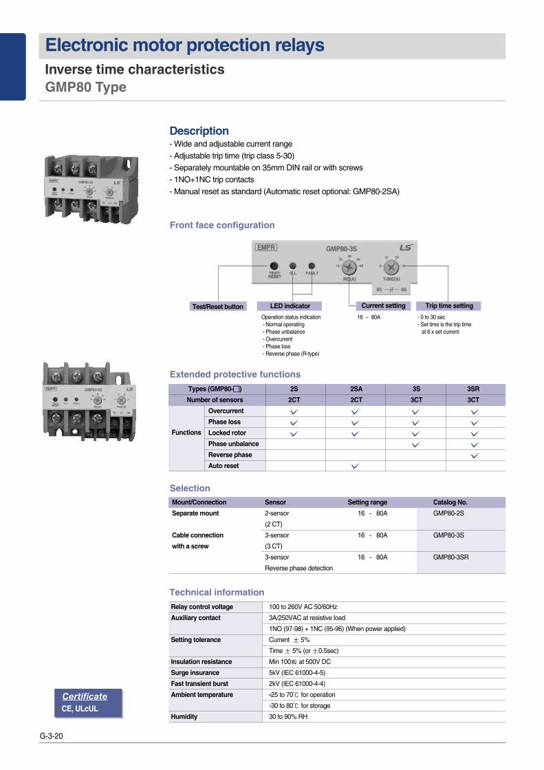
Description - Wide and adjustable current range- Adjustable trip time (trip class 5-30)- Separately mountable on 35mm DIN rail or with screws- 1NO+1NC trip contacts- Manual reset as standard (Automatic reset optional: GMP80-2SA)
SelectionMount/Connection Sensor Setting range Catalog No.
Separate mount 2-sensor 16 - 80A GMP80-2S
(2 CT)
Cable connection 3-sensor 16 - 80A GMP80-3S
with a screw (3 CT)
3-sensor 16 - 80A GMP80-3SR
Reverse phase detection
Relay control voltage 100 to 260V AC 50/60Hz
Auxiliary contact 3A/250VAC at resistive load
1NO (97-98) + 1NC (95-96) (When power applied)
Setting tolerance Current ± 5%
Time ± 5% (or ±0.5sec)
Insulation resistance Min 100㏁ at 500V DC
Surge insurance 5kV (IEC 61000-4-5)
Fast transient burst 2kV (IEC 61000-4-4)
Ambient temperature -25 to 70℃ for operation
-30 to 80℃ for storage
Humidity 30 to 90% RH
Technical information
CertificateCE, ULcUL
Front face configuration
Extended protective functions
Types (GMP80-��) 2S 2SA 3S 3SR
Number of sensors 2CT 2CT 3CT 3CT
Overcurrent
Phase loss
Locked rotor
Phase unbalance
Reverse phase
Auto reset
Functions
16 ~ 80A
Current settingTest/Reset button LED indicator
Operation status indication- Normal operating- Phase unbalance- Overcurrent- Phase loss - Reverse phase (R-type)
Trip time setting
- 0 to 30 sec - Set time is the trip time
at 6 x set current

G-3-21
EMP
R/D
MP
R
G3
Characteristics DMP Series DMP-S(a)/SZ(a)/SI Type
�Unit type or extension type is available - Extension type: Remotely mounts the display unit on the panel surface �Ampere meter function: current and setting value by press the display button �Select the inverse time or definite time�Display the causes of the fault and the values�Load ratio is displayed up to setting current
Protect function
Note) Lock protection is operated after setting D-time in case of definite time type
Note) 1. 2.dEF is only displayed when dEF is selected in a 1.CHA mode2. Functions for b to e are available for only Sa & SZa type.
Over current Depend on setting time Selectable the inverse/definite
Phase failure Within 3seconds Over 70% of the rate of unbalance
Phase unbalance Within 5seconds Over 50% of the rate of unbalance
Reverse phase Within 0.1seconds Function enable
Stall Within 5seconds Over 180% of the setting current
Lock Within 0.5seconds Setting 200~900% of rated current
Under current Within 3seconds Setting 30~70% of rated current
Function selectionFUNC Sel Description1. CHA Inv/dEF Operating characteristics setting (Inverse/definite time type)
2. dEF Note1) 0~30 (S) Setting the operating time (In definite type)
3. r.P oFF/on Reverse phase enable
4. Und oFF/30~70 (%) Under current enable and setting
5. Alt oFF/60~110 (%) Alerting enable and setting
6. Stl oFF/on Stall enable
7. Loc oFF/200~900 (%) Lock enable and setting
8. Ct 1~120 CT ratio setting
9. P.F on/oFF Phase fault enable
b. StA Note2) 0~120 Operating time setting by month
c. StH 10~730 Operating time setting by hour
d. tAH A000,000.0 Displaying total operating time (month, hour)
E. rAH A000,000.0 Displaying operating time (month, hour)
Sto Sto Store
Ratings Model DMP��-S/Sa DMP��-SZ/SZa/SIType Wiring method Screw
Panel mount Unit or Extension
Operating characteristics Inverse/definite type
Alerting function Variable between 60 and 110%
Current range (A) 06: 0.5~6, 36: 3~36, 60: 5~60
Setting time Definite Delay (D-T) 0~60seconds
Operating (O-T) 0~30seconds
Inverse 0~60seconds
Reset type Manual reset
Operating Voltage AC 110V or AC 220V
voltage Frequency 50/60Hz
Aux. contacts OL 2-SPST (95~98) 3A/250Vac resistive load
AL SPST (07-08) 3A/250Vac resistive load
Indicate 7-segment 3-phase current value, fault cause
Bar-LED arrays Load ratio (60~110%)
Mounting 35mm Din-rail/Panel
Certification UL, cUL, CE
Extention type (with cable)
G-3-22
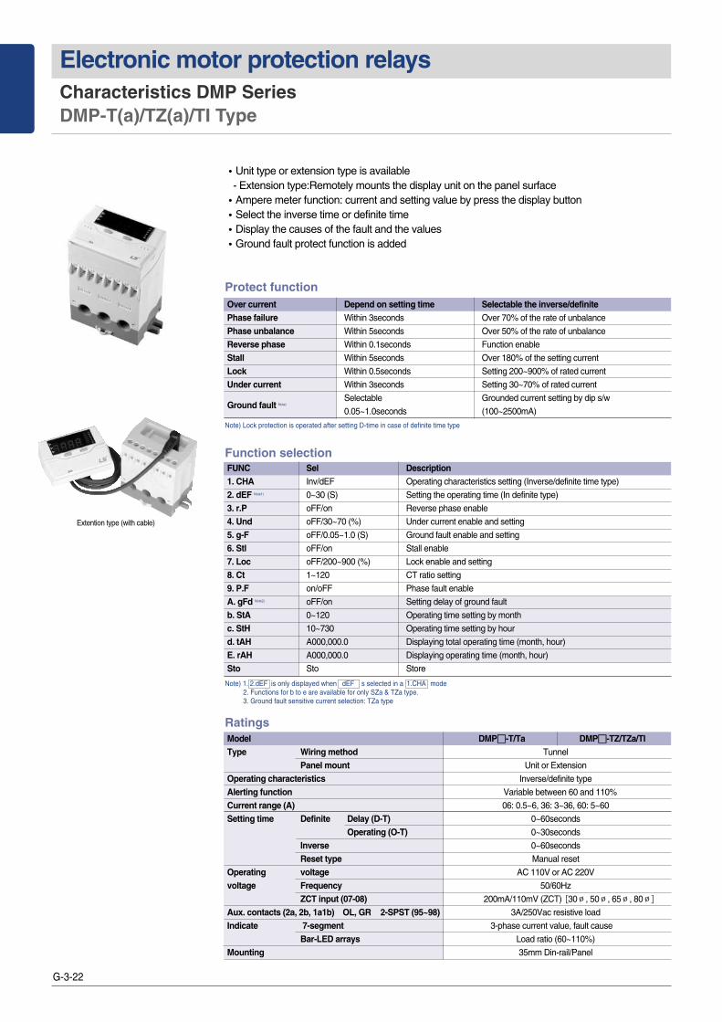
Electronic motor protection relays Characteristics DMP Series DMP-T(a)/TZ(a)/TI Type
�Unit type or extension type is available - Extension type:Remotely mounts the display unit on the panel surface �Ampere meter function: current and setting value by press the display button �Select the inverse time or definite time�Display the causes of the fault and the values�Ground fault protect function is added
Protect function
Note) Lock protection is operated after setting D-time in case of definite time type
Note) 1. 2.dEF is only displayed when dEF s selected in a 1.CHA mode2. Functions for b to e are available for only SZa & TZa type.3. Ground fault sensitive current selection: TZa type
Over current Depend on setting time Selectable the inverse/definitePhase failure Within 3seconds Over 70% of the rate of unbalance
Phase unbalance Within 5seconds Over 50% of the rate of unbalance
Reverse phase Within 0.1seconds Function enable
Stall Within 5seconds Over 180% of the setting current
Lock Within 0.5seconds Setting 200~900% of rated current
Under current Within 3seconds Setting 30~70% of rated current
Ground fault Note) Selectable Grounded current setting by dip s/w
0.05~1.0seconds (100~2500mA)
Function selectionFUNC Sel Description1. CHA Inv/dEF Operating characteristics setting (Inverse/definite time type)
2. dEF Note1) 0~30 (S) Setting the operating time (In definite type)
3. r.P oFF/on Reverse phase enable
4. Und oFF/30~70 (%) Under current enable and setting
5. g-F oFF/0.05~1.0 (S) Ground fault enable and setting
6. Stl oFF/on Stall enable
7. Loc oFF/200~900 (%) Lock enable and setting
8. Ct 1~120 CT ratio setting
9. P.F on/oFF Phase fault enable
A. gFd Note2) oFF/on Setting delay of ground fault
b. StA 0~120 Operating time setting by month
c. StH 10~730 Operating time setting by hour
d. tAH A000,000.0 Displaying total operating time (month, hour)
E. rAH A000,000.0 Displaying operating time (month, hour)
Sto Sto Store
Ratings Model DMP��-T/Ta DMP��-TZ/TZa/TI Type Wiring method Tunnel
Panel mount Unit or Extension
Operating characteristics Inverse/definite type
Alerting function Variable between 60 and 110%
Current range (A) 06: 0.5~6, 36: 3~36, 60: 5~60
Setting time Definite Delay (D-T) 0~60seconds
Operating (O-T) 0~30seconds
Inverse 0~60seconds
Reset type Manual reset
Operating voltage AC 110V or AC 220V
voltage Frequency 50/60Hz
ZCT input (07-08) 200mA/110mV (ZCT) [30∅, 50∅, 65∅, 80∅]
Aux. contacts (2a, 2b, 1a1b) OL, GR 2-SPST (95~98) 3A/250Vac resistive load
Indicate 7-segment 3-phase current value, fault cause
Bar-LED arrays Load ratio (60~110%)
Mounting 35mm Din-rail/Panel
Extention type (with cable)

G-3-23
EMP
R/D
MP
R
G3
Characteristics IMP Series IMP-C Type
�MODBUS RS-485 Communication or 4~20mA analogue output�3 phase ampere meter function: Check the 3 phase current and setting value by press the
display button �Select the Thermal inverse/inverse time or definite time�Easy to operate: Set the most function by the operation button and knob�Display the causes of the fault and the values�Adjustable wide current range (0.5~100A)
Protect function
Note) 1. Lock protection is operated after setting D-time in case of definite time selected.2. 12. gF Zero sequence CT, 13. gn Residual circuit sensing.
Over current Depend on setting time Selectable the inverse/definitePhase failure Within 1.5seconds Over 70% of the rate of unbalancePhase unbalance Within 3seconds 10~70% of the rate of unbalanceReverse phase Within 0.1seconds Function enableStall Within 3seconds setting 150~500% of rated currentLock Note1) Within 0.5seconds Setting 200~800% of rated currentUnder current Within 3seconds Setting 30~90% of rated current
Ground fault Note2) Selectable 0.05, gF: 0.03/0.05/0.1~3A0.1~1.0seconds gn: 20~500% of the FLC min
Ratings Model IMP-C-NO, M485, A420Type Wiring method Tunnel
Panel mount Unit or Extension
Operating characteristics defin/TH-Inv./n-TH
Alerting function Variable between 60 and 110%
Current range (A) 0.5~100
Setting time Definite Delay (D-T) 1~200seconds
Operating (O-T) 0~30seconds
Inverse/TH-Inverse time 0~60seconds
Reset type Manual reset
Operating voltage AC 85~245V, 50/60Hz
ZCT input (07-08) 200mA/110mV (ZCT) [30∅, 50∅, 65∅, 80∅]
Aux. contacts (2a, 2b, 1a1b) OL, GR 2-SPST (95~98) 5A/250Vac resistive load
Indicate 7-segment 3-phase current value, fault cause 5point
Bar-LED arrays Load ratio (60~110%)
Mounting 35mm Din-rail/Panel
Communication A420: Analog, M485: Modbus
Certification CE
Setting Menu (A Group) Setting Menu (B Group)
1.CHA dEF/th/n-th Operation Characteristics (Definite Time /
n-thHeat Accumulation Inverse Time /Inverse Time)
2.O-t 1~60s Operation Time (sec) 60
3.d-t 1~200s Operation Delay (sec) In chase of dEF
4.r-C 0.5~10A/5~100A Rated Current Max.
5.Ctr 0.25, 0.5, 1~200 CT Ratio (4 times, twice, once) 1
6.Loc OFF, 200~800% Lock Protection (sec) OFF
7.StL OFF, 150~500% Stall Protection (sec) OFF
8.P-F OFF/On Open Phase OFF
9.P-U OFF, 10~70% Unbalance Protection (%) OFF
10.rP OFF/On Reverse Phase OFF
11.UC OFF, 30~90% Low Current Protection (%) OFF
12.gF 0FF, 0.03, 0.05/0.1~3AGround Fault Operation Current (Zero-Phase-Sequence Current) (A) OFF
13.gn OFF, 20~500% (FLCmin)Ground Fault Operation Current (Post-Arc Current) (FLCmin) OFF
14.gt 0.05, 0.1~1.0s Ground Fault Operation Time (Current) -
15.gd On/OFF Ground Fault Delay During Start ON
16.IC OFF, 500~1000% Instantaneous Protection (%) OFF
17.Io ALt/TriP Instantaneous Warning/Operation TriP
1.E-r On/OFF Electric Recovery On
2.A-r OFF, 1~20 min Automatic Recovery (Minute) OFF
3.r-t Hour/Minute Operation Time Time Check
4.Srt OFF, 1~8760Hour Operation Time Setup (Hour) -
5.s-d 2009/01.01/00:00 YY/MM/DD/ HH:MM -
6.Trt Day/hour:minute Total Operation Time Time Check
A.t-d 0.5~10/5~100A 20mA Output Setup A420
A.Adr 1~247 Communication Address
b.bps 96/192/384 Communication Speed
c.S-P On/OFF SWAP
Note) 1. When the power is supplied first or is resupplied after a powerfailure, must set up the date (5.S-d).
2. Automatic recovery is only possible in case of an excesscurrent trip.
Note) 1. When the rated current S/W is 100A, the CT ratio is not displayed.2. Some menus are not displayed if relevant functions are not available.
M485 Model
Menu Setting Value Item Default Value Menu Setting Value Item Default Value
Extention type (with cable)

G-3-24
Electronic motor protection relays Setting method GMP Series Inverse time
Condition LED Status LED Diagram Remark
Operating status
Tripped status
Phase failure (3CT)
GMP 80-3S/3SR model, onlyred color LED will flicker.
GMP 80-3S/3SR model,O.L LED will light up andalso FAULT LED will flicker.
GMP 80-3S/3SR model,Red/Green LED will flicker.
Note) There are two red color LEDs for O.L (Overload) & Fault in the model of GMP80-3S/SR
LED OFFNormal
Over current
Phase unbalance(30~50%)
Over current
R
S
T
Phase failure (2CT)
Reverse phase (3CT)
0.4 Secondintervals
0.4 Secondintervals
O.L LED light up
1 time for 3seconds
2 time for 3seconds
2 time for 3seconds
Red LED light up for 0.9 secLED goes off for 0.1 sec
Red & Green color LEDflicker alternately
1. Check the rated voltage and apply the control power to A1 and A2 terminal
2. Check the TEST/RESET button 1) When you press the ‘Test/Reset’ button, the O.L LED is turned on and the EMPR is tripped2) When you press the ‘Test/Reset’ button under the EMPR is tripped, the O.L LED is turned
off and the EMPR is reset3) Auto reset function: When it is tripped by the over current, it is reset after 1 Min.(Optional)
3. Set the operating timeThe operating time is set on the base of 600% of the rated current in the characteristic curve1) Set the operating time by considering the operating time and start current according to the
types of the load2) If the time knob is set to 10sec, the EMPR is tripped when the start current (600% of the
rated current) is applied for 10secCaution) The EMPR with inverse time characteristics can be tripped to protect the motor when the motor is started a few times continuously
When a motor is frequently changing the rotating direction (forward and reverse), set the operating time longer For the crane and hoistuse, select the EMPR with definite time characteristics
4. Set the operating currentSet the current by considering the rated current of a motor to protect from the over current1) Check the rated current of a motor is within the current setting range of an EMPR2) Set the ‘RC’ (Rated current) knob to the maximum value and then start a motor3) Under normal motor operation, rotate the ‘RC’knob to the counterclockwise until the‘O.L’LED flickers The current at this point in the 100% current rating under real load
4) At this point, rotate the ‘RC’knob to the clockwise until the ‘O.L’LED turned off. Ex) When the ‘O.L’ LED flickering at 20A, the setting current will be 22A(=20x1.1)Note) The brackets for connection is offered standard
5. Check status of operation by LED1) In case of overcurrent
If there will be an overcurrent during motor operation, the red color of LED will flicker at 0.4second intervals. After tripping because of overcurrent, the red color of LED will light up.
2) In case of phase failureIf there will be a phase failure in three phase load, it will be tripped within 3 seconds.Note) 2CT EMPR can protect motor from R or T phase failure.
3) In case of phase unbalanceIf phase unbalance rate is over 50%, FAULT LED will flicker 0.4 second intervals.
4) In case of Reverse phaseRed & green color LED will flicker alternately.
G-3-25
EMP
R/D
MP
R
G3
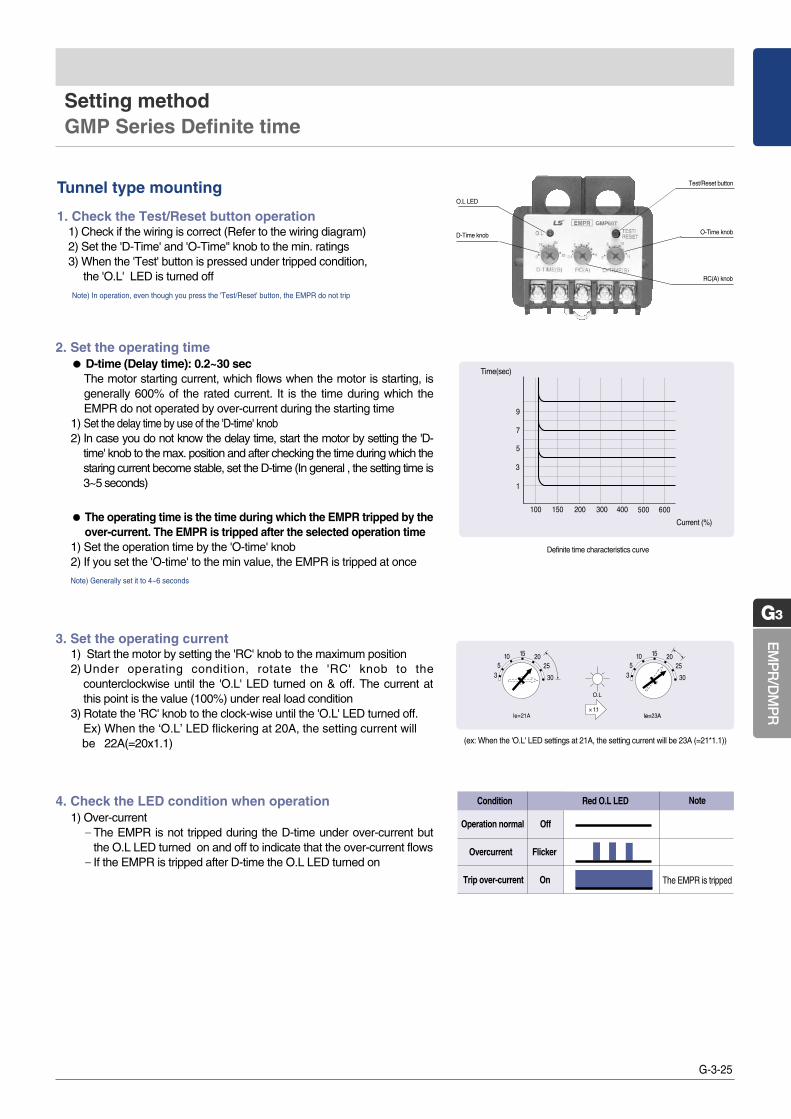
2. Set the operating time ●● D-time (Delay time): 0.2~30 sec
The motor starting current, which flows when the motor is starting, isgenerally 600% of the rated current. It is the time during which theEMPR do not operated by over-current during the starting time
1) Set the delay time by use of the 'D-time' knob2) In case you do not know the delay time, start the motor by setting the 'D-
time' knob to the max. position and after checking the time during which thestaring current become stable, set the D-time (In general , the setting time is3~5 seconds)
●● The operating time is the time during which the EMPR tripped by theover-current. The EMPR is tripped after the selected operation time
1) Set the operation time by the 'O-time' knob2) If you set the 'O-time' to the min value, the EMPR is tripped at once
Note) Generally set it to 4~6 seconds
Definite time characteristics curve
Time(sec)
Current (%)
Test/Reset button
RC(A) knob
O-Time knob
O.L LED
D-Time knob
1. Check the Test/Reset button operation1) Check if the wiring is correct (Refer to the wiring diagram)2) Set the 'D-Time' and 'O-Time'' knob to the min. ratings3) When the 'Test' button is pressed under tripped condition,
the 'O.L' LED is turned off
Note) In operation, even though you press the 'Test/Reset' button, the EMPR do not trip
Tunnel type mounting
Setting method GMP Series Definite time
(ex: When the 'O.L' LED settings at 21A, the setting current will be 23A (=21*1.1))
4. Check the LED condition when operation1) Over-current‐The EMPR is not tripped during the D-time under over-current but
the O.L LED turned on and off to indicate that the over-current flows‐If the EMPR is tripped after D-time the O.L LED turned on
Note
The EMPR is tripped
Condition Red O.L LED
Operation normal Off
Overcurrent Flicker
Trip over-current On
3. Set the operating current1) Start the motor by setting the 'RC' knob to the maximum position2) Under operating condition, rotate the 'RC' knob to the
counterclockwise until the 'O.L' LED turned on & off. The current atthis point is the value (100%) under real load condition
3) Rotate the 'RC' knob to the clock-wise until the 'O.L' LED turned off. Ex) When the ‘O.L’ LED flickering at 20A, the setting current will be 22A(=20x1.1)

G-3-26
Electronic motor protection relays
●● Function & Setting menu1) Automatic reset setting will work in the event of overcurrent trip 2) Func. A and b are to check the elapse time, not for setting 3) Undercurrent protection function will work at the current flow more than 0.4A 4) In case of changing the rating DIP S/W FUNC #1 should be changed accordingly 5) Function setting is allowable at TEST mode
- Turn off the power before changing a current type switch, and then be sure to adjust the current in the menu
Setting method GMP60-TD(a) Type
●●Setting Menu
●●Fault status configuration
Note) 1. If operation hour set at is elapsed is displayed and the relay operates normally. (There is no additional relay output)2. How to check and
3. When power is OFF the data in unit of minute is deleted at4. Operation hour at is the total running hour before the motor is oFF and displayed in Day, Hour and Min.
When motor is OFF the data is deleted.
Display How to checkPress SEL Day displayed Press SEL Hour, Min displayedPress SEL Operation hour displayed Press SEL Day displayed Press SEL Min displayed
Current type selection Set the same with rated current S/W
Trip time setting -
Time delay setting -
Rated current setting -
Current ratio setting -
Phase loss enable -
Undercurrent setting For TDa model only
Automatic reset setting For TDa model only
Operation hour setting For TDa model only
Total running hour check For TDa model only
Running hour check For TDa model only
Store -
FUNC SEL Description Remarks
Over current O - L More than set current : Within the set time
Undercurrent U - C Lower than the undercurrent set ratio : Within 3S GMP60TDa
Phase LossPF - r Over 70% of the rate of unbalance : Within 3S R Phase Loss
PF - t Over 70% of the rate of unbalance : Within 3S T Phase Loss
LOCK Loc More than lock set current ratio : Within 1S
ApproachingOrH When Running time approaches at setting time GMP60TDa
Running Time
Protection FND Description Remarks
Note) When the ‘FUN’ Key and ‘SEL’ Key are pushed simultaneously, a last trip cause appears on the disply window.

G-3-27
EMP
R/D
MP
R
G3
Setting method GMP60-3TZ(R) / 3TN(R) Type
●● Trip curve: definite time characteristics
●● Protective function: overcurrent, locked rotor, phase loss, phaseunbalance, ground fault (and phase reverse)1) Overcurrent: trip within 3 sec. after D-time at 105% or more2) Locked rotor: trip within 1 sec. after D-time at 300% or more3) Phase loss: trip within 3 sec. (phases unbalance rate over 70%)4) Phase unbalance: trip within 5 sec. (phases unbalance rate over 50%)5) Ground fault: trip within 0.5 sec. after D-time at over 110% or under
90% of set value6) phase reverse: trip within 1 sec. when any two phases out of three
●●Overcurrent trip time1) Time delay(D-time) setting: between 0.2-60 sec.2) Trip time(O-time) setting: fixed at 3 sec.
●● Last fault cause data stored- to display it press TEST/RESET button 2 times within 0.5 sec.- PWR LED flicking in case of no faultNote) In case of load less than minimum rating of EMPR make the number of penetrating through CT more than 2 times.
If not, error may happen to phase loss .
Note) 1.Make power off before changing the rated current with S/W ①2.The setting range of RC (A) KNOB ⑥ is recognized as 0.5 ~ 6A or 5 ~
60According to the setting value of S/W ①. The value of the scale forRC (A) KNOB ⑥ is 0.5, 1, 2, 3, 4, 5, 6 or 5, 10, 20, 30, 40, 50,60(A)from the left.
3.Last fault cause function indicates the LED status for the last TRIP.
①
②
③
④
⑤
⑥
⑦
⑧
Function Setting RemarkDescriptionNO
①
⑤ ⑥ ⑦
⑧
② ③ ④
Red LEDGreen LED
●● Status of LED configuration
6A/60A Slide switch Maximum rated current (6A/60A) setting -
PWR. Red LED Lights up when power is ON Blinking in the failure mode
Overcurrent / unbalance in progress:
Overcurrent TRIP:
Phase loss (unbalance) TRIP
FAULT Red / Green LED ∙R-phase:
∙S-phase:
∙T-phase:
Reverse phase:
GF Red LED Lights up after blinking in the event of ground fault -
D-TIME (S) KNOB Delay time (0.2 to 60 sec.) -
RC (A) KNOB Rated current setting: 0.5~6A/5~60A -
GR (A) KNOBSensitivity current setting (0.1~2.5A) Zero phase current detection type
Sensitivity current setting (0.5~6A) Residual current detection type
TRIP / RESET alternately perform Pressing 2 times within 0.5 sec.
TEST/RESET BUTTON 1. Check relay contacts - displays fault cause the final failure
2. RESET cause is displayed

G-3-28
Electronic motor protection relays
1) First shift to the test mode by press the ”Test/Reset”button and then set the functions by press the ”FUNC”button
2) Each time you press the”FUNC”button, the function mode switches from 1.CHA mode to Sto mode. When the mode that you want to change is displayed, push the ”Sel”button to select the value you want. After you select the value, press the ”FUNC”button to finish the settings and it displays the next mode
3) If no button is pressed in the selection mode, it remains in that mode
4) If you select the inverse time characteristics it skips the mode 2
(Definite O-time) and go to the mode 3 (Reverse phase)
5) Alt is the alert setting mode. It displays the load rate of the current
setting value by the bar LED (60~110%)- If the current is higher than the setting value, the bar LED is switched on and off and the AL relay (07-08) make close and open in 1sec interval unit the EMPR is tripped (Pre-alarm function)
- If the 5. Alt mode is set to off, the AL relay make close after the EMPR is tripped (Normal open contact)
6) To finish the settings you have to press the ”Sel”button in the Stomode
Setting method DMP Series
1. Check the operation of the Test/Reset button1) Check the wiring method 2) Press the Test/Reset button and then test is displayed on
the LED and the DMPR is tripped3) Press the Test/Reset button again and then it is reset
Note) The Test/Reset is not available when a motor is rotating.
Note) 1. Set the under current value from above 350mA2. Do not change the CT ratio in 36, 60 type
2. Shift the mode by pressing the FUNC key and then select the values by the Sel key
R phase
S phase
T phase
Test/Reset button
FUNC button
Current knob
Digital display
Bar graph
Display button
Sel button
Time knob
FUNC Sel Functions Note
Inverse or definite time characteristics Default is inverse time characteristics
Set the O-time (Definite time only) For D-time setting, use the time knob
Reverse phases protection Default is “Off”
Under current protection Default is “Off”Note1)
Alarm function (With pre-alarm function) Default is “Off”
Ground fault and Setting the operating time Default is “Off”(Z type)
Stall function Default is “Off”
Lock function Default is “Off”
CT ratio Default is 1:1 Note2) (DMP06 Modle)
Phase failure Default is “On”to store
Setting delay of Ground Fault Available for SZa/TZa
Operating time setting (Month)
Operating time setting (Hour)DMP�-Sa/Ta/SZa/TZa model
Displaying total operating time (Month, Hour)
Displaying operating time (Month, Hour)
Store Push the SEL button to store
On
Off
5.ALt AL(07-08) contact operation
Alarm signal (Alert function)
1
0
1
0
Normal
Alert settingvalue
Trip settingvalue
Alarm Trip
Setting Menu

G-3-29
EMP
R/D
MP
R
G3
Setting method DMP Series
3. Adjust the operating time by the time knob●● Inverse time characteristics1) Select the inverse time in the 1. CHA mode, the default operating time is 600% of the setting
current2) The setting range of the operating time is 0~60sec. Set the time by considering the motor
start time3) When it is over the setting time, the EMPR operate in accord with the hot characteristics curve
●● Definite time characteristics1) Select the definite in the 1. CHA mode, it is operated by the definite time characteristics2) D-time means the time that delays the operating time when the motor is starting 3) The setting range of the operating time is 0~60sec. Set the time by considering the motor
start time4) Set the O-time at the setting mode 2. dEF and the range is 0~30sec
4. Adjust the operating current by the current knob1) Set the operating current based on the rated current that is described in the name plate.
Generally set the 110~115% of the real load current in the normal load condition2) There are 3 types according to the current range (6 / 36 / 60). When you use the external CT
you can see the real current by setting the CT ratio3) You can easily set the current value by refer to the load rate which is displayed on the bar-
graph (Approx. 90% load rate)
5. Check the setting state by the display key1) In normal condition it display the maximum current among the three phase current2) Each time you press the “Display”button you can see the current and values 3) If no button is pressed for 3~4 seconds. It returned to the normal condition
6. Check the causes of the fault by look at the display unit The causes of the fault is switched on and off for 0.5sec interval. If you press the “Display”button at this time, you can see the values and the causes of the fault
R phase current
S phase current
T phase current
5A setting
Set the D-time to 10sec
(Set the motorstarting time)
Set the O-time to 10sec
(Display only indefinite time) Normal condition
R
S
T
R
S
T
R
S
T
R
S
T
R
S
T
R
S
T
Overload
Turn on
Turn on & off
ex)
Zero current sensitivity setting Sensitivity DIP S/W
(mA) 1 2 3 4
100 � � � �
200 1 � � �
500 � 1 � �
1000 � � 1 �
1500 � � � 1
2000 � � 1 1
2500 1 1 1 1
Note) 1. Please use ZCT for LS EMPR.
R
S
T
R
S
T
R
S
T
R
S
T
R
S
T
R
S
T
R
S
T
Under current Reverse phase
Phase fail Ground fault
Stall Short circuit
Lock

G-3-30
Electronic motor protection relays Operation and Setting IMP Series
1. Test/Reset1) Check wires.2) Press the Test/Reset key once. Then “TEST”is displayed and the EMPR is tripped.3) Press again the Test/Reset key to reset the EMPR.
Note) While the motor is running, the Test/Reset key does not work.
2. Setting1) Press the Test/Reset key once. Then “TEST”is displayed and the EMPR is tripped.2) Press the Enter key. Then “P-99”is displayed. Use the Up/Down keys to change the password.3) Press the Enter key to enter A-gr setup mode.
Use the Up/Down keys to select a group and Press the Enter key to enter the selected group.Press the Test/Reset key to move back to the previous mode.
4) In the A-Grp mode, Press the Enter key. Then “1.CHA”is displayed.Use the Up/Down keys to select an item and Press the Enter key to enter the selected item.Press the Test/Reset key to move back to the previous mode.
5) Use the Up/Down keys to set up the value and Press the Enter key to save it. Note) When the power is supplied first or is resupplied after a power failure, must set up the date in b-gr, 5.S-d.
Set up the rated current S/W while the power is off.
3. Quick Setup1) Press the “Up and Enter”keys at the same time. “UPLD”is displayed and settings are uploaded
to the display.2) Insert the display to the body without settings, and then press the Test key to enter the test mode.3) Press the “Down and Enter”keys at the same time. “TEST”is displayed and downloading is
completed.4) Press the Test key to return to the normal mode.
Note) Communication settings cannot be uploaded or downloaded.
4. Setting Checkup1) Press the Enter key.2) Use the Up/Down keys to select a group and Press the Enter key to enter the selected group.
Press the Test/Reset key to move back to the previous mode.3) Use the Up/Down keys to select an item and Press the Enter key to enter the selected item. 4) Press the Enter key again to check settings.
5. Failure Event Checkup1) Press the Up and Down keys at the same time to display “1.O-C”(recent failure events).
Note) When no failure events are stored, “1.non3”is displayed.
2) Use the Up/Down keys to select an event and press the Enter key to go to the selected event. 3) The R-phased failure current is displayed. Every time the Down key is pressed, S-phased failure
current, Tphased failure current, overload rate and date are displayed one after the other.4) Press the Test/Reset key to move back to the previous mode.5) Press the Up and Down keys at the same time to get out of the failure event checkup mode.
6. Forced Thermal ResetWhen the system is tripped while it is in the thermal inverse time mode, if you want to turn theEMPR into the cold mode by resetting the motor’s heat amount, Press the Enter and Test/Restkeys at the same time.* When a trip occurs due to the thermal excess current, if the motor is started right after it is reset, as the motor is
hot, it is highly likely that the motor is tripped again.

G-3-31
EMP
R/D
MP
R
G3
Operation and Setting IMP Series
Note) 1. When the rated current S/W is 100A, the CT ratio is not displayed.2. Some menus are not displayed if relevant functions are not available.
Group Menu Setting Value Description Default Value
A1.CHA dEF/th/n-th
Operation Characteristics(Definite/Thermal Inverse/Inverse)
n-th (Inverse)
2.O-t 1~60s Operation Time (sec) 60
3.d-t 1~200s Delay Time (sec) 200
4.r-C 0.5~10A/5~100A Rated Current (10/100A) 10/100A
5.Ctr 0.25, 0.5, 1~200 CT Ratio (4 times, twice, once) 1Note)
6.Loc OFF, 200~800% Lock Protection (sec) OFF
7.StL OFF, 150~500% Stall Protection (sec) OFF
8.P-F OFF/On Open Phase OFF
9.P-U OFF, 10~70% Unbalance Protection (%) OFF
10.rP OFF/On Reverse Phase OFF
11.UC OFF, 30~90% Under Current Protection (%) OFF
12.gF 0FF, 0.03, 0.05/0.1~3AGround Fault Operation Current (Zero sequence CT)
OFF
13.gn OFF, 20~500% (FLCmin)Ground Fault Operation Current (Residual circuit)
OFF
14.gt 0.05, 0.1~1.0s Ground Fault Operation Time -
15.gd On/OFF Ground Fault Delay During Start ON
16.IC OFF, 500~1000% Instantaneous Protection (%) OFF
17.Io ALt/TriP Instantaneous Warning/Operation TriP
Group Menu Setting Value Description Default Value
B 1.E-r On/OFF Electric Reset On
2.A-r OFF, 1~20 min Automatic Reset OFF
3.r-t Hour/Minute Run Time Time Check
4.Srt OFF, 1~8760Hour Run Time Setup (Hour) -
5.s-d 2009/01.01/00:00 YY/MM/DD/ HH:MM (View/Setup) -
6.Trt Day/hour:minute Total Run Time Time Check
A.t-d 0.5~10/5~100A Analog output A420 Model
A.Adr 1~247 Communication Address
b.bps 96/192/384 Communication Speed
c.S-P On/OFF SWAP
Note) 1. When the power is supplied first or is resupplied after a power failure, must set up the date (5.S-d).2. Automatic reset is only possible in case of an excess current trip.
M485 Model
Setting Menu (A Group)
Setting Menu (B Group)
G-3-32
Electronic motor protection relays Operation and Setting IMP Series
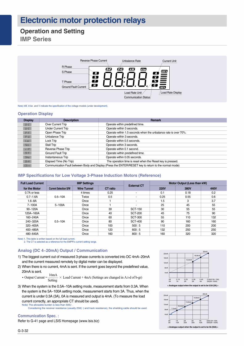
Operation Display
R Phase
S Phase
T Phase
Ground Fault Current
Unbalance Rate Current Unit
Load Rate Unit
Communication Status
Load Rate Display
Reverse Phase Current
Over Current Trip Operate within predefined time.Under Current Trip Operate within 3 seconds.Open Phase Trip Operate within 1.5 seconds when the unbalance rate is over 70%.Unbalance Trip Operate within 3 seconds.Lock Trip Operate within 0.5 seconds.Stall Trip Operate within 3 seconds.Reverse Phase Trip Operate within 0.1 second.Ground Fault Trip Operate within predefined time.Instantaneous Trip Operate within 0.05 seconds.Elapsed Time (No Trip) The operation time is reset when the Reset key is pressed.Communication Fault between Body and Display (Press the ENTER/RESET key to return to the normal mode)
Note) 1. This table is written based on the full load current.2. The CT is selected as a reference for the EMPR’s current setting range.
IMP Specifications for Low Voltage 3-Phase Induction Motors (Reference)
Note) kW, kVar, and V indicate the specification of the voltage models (under development).
Analog (DC 4~20mA) Output / Communication1) The biggest current out of measured 3-phase currents is converted into DC 4mA~20mA
and the current measured remotely by digital meter can be displayed.2) When there is no current, 4mA is sent. If the current goes beyond the predefined value,
20mA is sent.
3) When the system is the 0.5A~10A setting mode, measurement starts from 0.3A. Whenthe system is the 5A~100A setting mode, measurement starts from 3A. Thus, when thecurrent is under 0.3A (3A), 0A is measured and output is 4mA. (To measure the loadcurrent correctly, an appropriate CT should be used). Note) The allowable burden is less than 500Ϊ .
Considering the receiver resistance (usually 250Ϊ ) and track resistance), the shielding cable should be used.
Communication Spec. :Refer to G-41 page and LSIS Homepage (www.lsis.biz)
�Output Current = 16mA
× Load Current + 4mA (Settings are changed in A.t-d of b-gr)Setting
20mA
13.6mA
16.8mA20mA
16mA
12mA
8mA
4mA
0A 0.1A 0.2A 0.3A 0.4A 0.5A(0.5A~10A)0A 1A 2A 3A 4A 5A(5A~100A)
20mA
10.4mA
13.6mA
7.2mA
16.8mA20mA
16mA
12mA
8mA
4mA
0A 1A 2A 3A 4A 5A(0.5A~10A)0A 10A 20A 30A 40A 50A(5A~100A)
< Analogue output when the output is set to be 0.5A (5A) >
< Analogue output when the output is set to be 5A (50A) >
Display Description Remark
Full Load Current IMP SettingsExternal CT
Motor Output (Less than kW)
for the Motor Current Selection S/W Wire Tunnel CT ratio 220V 380V 440V0.7A or less 4 times 0.25 - 0.1 0.18 0.2
0.7~1.6A 0.5~10A Twice 0.5 - 0.25 0.55 0.61.6~8A Once 1 - 1.5 3 3.77~100A 5~100A Once 1 - 25 45 5590~120A Once 30 SCT-150 30 55 55
120A~160A Once 40 SCT-200 45 75 90160~240A Once 60 SCT-300 55 110 132240~320A 0.5~10A Once 80 SCT-400 90 160 160320~400A Once 100 500 : 5 110 200 200400~480A Once 120 600 : 5 132 250 250480~640A Once 160 800 : 5 160 320 320

G-3-33
EMP
R/D
MP
R
G3
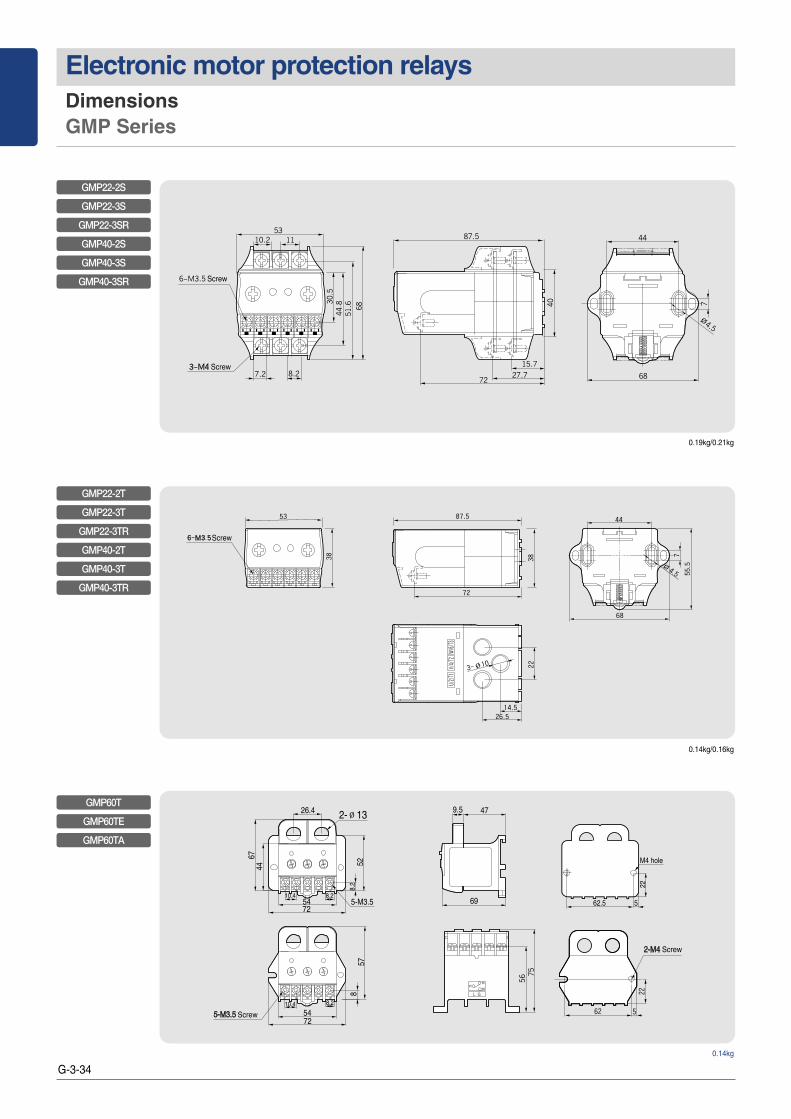
Dimensions GMP Series
Screw
Screw
Screw
Screw
Screw
Screw
0.15kg
0.18kg
0.20kg/0.22kg
GMP22-2P (1c) Sol
GMP22-2PD (1c) Sol
GMP22-2P (1a1b) Sol
GMP22-3P Sol
GMP22-2PA (1a1b) Sol
GMP22-3PR Sol
GMP40-2P Sol
GMP40-2PD Sol
GMP40-2PA Sol
GMP40-3P Sol
GMP40-3PR Sol
Screw
Screw
Mounting hole
0.42kg/0.46kg
GMP80-2S
GMP80-3S
GMP80-3SR
G-3-34
Electronic motor protection relays Dimensions GMP Series
Screw
0.14kg/0.16kg
GMP22-2T
GMP22-3T
GMP22-3TR
GMP40-2T
GMP40-3T
GMP40-3TR
Screw
Screw
0.19kg/0.21kg
GMP22-2S
GMP22-3S
GMP22-3SR
GMP40-2S
GMP40-3S
GMP40-3SR
Screw
Screw
0.14kg
GMP60T
GMP60TE
GMP60TA

G-3-35
EMP
R/D
MP
R
G3
Dimensions DMP Series
Note) 1. Only for the GMP60-TZR modle.2. Aux. Contacts are operate when power applied.
Terminal arrangement
GMP22-2P (1c)GMP22-2PD (1c)GMP22-2PA (1c)
GMP22-2P (1a1b)GMP22-3PGMP40-2P/3P
GMP22-2/3SGMP40-3/3SGMP80-2/3S
GMP22-2/3TGMP40-2/3T
GMP60-T/TE/TA GMP60-TDGMP60-TDa
GMP60-3TZ, TZRGMP60-3TN, TNRGMP60-3T/3TR
Note)
GMP60-3TZ, TZR
GMP60-3TN, TNR
GMP60-3T, TR
Tunnel type Screw type - Terminal lug sticking
26.8
7422±
0.5
7.2 8.2
55.472.8
10
6175
5.8 47
12.5
55.4
74
R2.5
R2.5
62.25GMP60-TD
GMP60-TDa
0.25kg

G-3-36
Electronic motor protection relays Dimensions DMP Series
Note) 1. In extension type, the digital EMPR is calibrated with combining the display unit and mainbodyso, please cautious not to combine the display unit and mainbody with different part No.
2. The 07-08 contacts are the ZCT input terminal (Digital EMPR with ground fault function)
DMP�-S
DMP�-SZ
DMP�-Sa
DMP�-SZa
DMP�-S
DMP�-SZ
DMP�-Sa
DMP�-SZa
※Aux. contact wire size : below 8[mm2]※Torque : 0.5N
Mounting dimensions
0.7kg
Panel mounting0.64kg
Panel cutting size
Mounting dimensions

G-3-37
EMP
R/D
MP
R
G3
Dimensions DMP Series
Note) 1. In extension type, the digital EMPR is calibrated with combining the display unit and mainbodyso, please cautious not to combine the display unit and mainbody with different part No.
2. The 07-08 contacts are the ZCT input terminal (Digital EMPR with ground fault function)
DMP�-T
DMP�-TZ
DMP�-Ta
DMP�-TZa
DMP�-T
DMP�-TZ
DMP�-Ta
DMP�-TZa
※Wire size to penetrate a CT :below 22[mm2]
0.56kg
Panel mounting0.5kg
Panel cutting size
Mounting dimensions
Mounting dimensions

G-3-38
Electronic motor protection relays Dimensions IMP Series
Note) The cable should be purchased separately (1m/1.5m/2m/3m).
M4
64
90
26 445617 17
2022
22
U/2/T1 V/4/T2 W/6/T3
90
68
64
135.
5
109.
3
53.5
∅17
21
5
7.3
4.2
82
25
U/2/T1 V/4/T2 W/6/T3
90
68
64
109.
3
53.5
∅17
21
5
12
121.
3
4.2
82
25
One-Body Type
Separate BOdy Type
Panel mounting

G-3-39
EMP
R/D
MP
R
G3
Wiring method GMP Series
Note) 1. The Z1, Z2 are the ZCT input terminal (GPM60-3TZ/TZ type)2. Aux. contacts are operate when power applied.
With the External CT
주)
GMP22-2P (1c)
GMP�-� (1a1b)
GMP60T (1c)
GMP60-3TZ, TZR
GMP60-3TN, TNR
GMP60-3T, 3TR

G-3-40
Electronic motor protection relays Wiring method DMP Series
DMP-S/Sa
DMP-T/Ta
With the External CT
Single phase
DMP-SZ/SZa
DMP-TZ/TZa
DMP-SZ/SZa
DMP-TZ/TZa
Note) When the single-phase motor is used, reverse phases protection should be set off.
주1)
With the External CT

G-3-41
EMP
R/D
MP
R
G3
Wiring method IMP Series
10A
100A
96 97 98 07 08 Z1 Z2
VT TRX(+) 05 06TRX(-)
ZCTA1 A2 95 96(+) (-)
VR VS VT
Note) 1. When the zero-phase-sequence current transformer is used to detect ground faults, connect the ZCT.2. When the single-phase motor is used, all phases are connected except the S phase, and open-phase, unbalance and ground fault should be set OFF.
Note) 1. The 3-phase voltage input terminal and 05-06 output terminal should be connected only for voltage protection models, which will be released in the future.2. For RS485 connection, the terminal resistance should be 120Ϊ .3. For 4~20mA current, the maximum burden should be less than 500Ϊ .
Engrave Description Remark
A1(+), A2(-) Input terminal for operation power AC/DC85~245V
95-96 When the power is ON (NC contact output) In case of an instantaneous trip, if 17.lo is ALT, it is NC, and if 17.lo is Trip, it is NO.
97-98 When the power is ON (NC contact output) In case of an instantaneous trip, regardless of 17 .1o setup, it is NC.
07-08 Converted to the NC mode only when an instantaneous trip occurs.
Z1, Z2 Output terminal for the zero-phase sequence current transformer Specific ZCT (for the EMPR)
TRX(+) RS485 terminal (TRX+) Or 4~20mA (+) outputM485, A420 Type
TRX(-) RS485 terminal (TRX-) Or 4~20mA (-) output
10A/100A Max. rated current change S/W 10A : 0.5~10A, 100A : 5~100A
VR/VS/VT 3-phase voltage input terminalN/A
05-06 Output terminal for voltage protection
10A
100A
96 97 98 07 08 Z1 Z2
VT TRX(+) 05 06TRX(-)
ZCTA1 A2 95 96(+) (-)
VR VS VT
ZCT
MC
OLTRIP
MCCBAUX
MCCB
RS485(4~20mA)
OFF(RESET)
SHT
Y
MC
A1 A2 95 97 07
Z1
TRX (+, -)
OLEMPR
96 98 08 Z2
SR
10A
100A
96 97 98 07 08 Z1 Z2
VT TRX(+) 05 06TRX(-)
ZCTA1 A2 95 96(+) (-)
VR VS VT
With the External CTNote 1)
Terminal Configuration
Terminal layout Communication specification
- Operation mode: Differential
- Distance: Max. 1.2km
- General RS-485 shielded twist 2-pair cable
- Baud rate: 9600/19200/38400bps
- Transmission method: half-Duplex
- Max. In/Output voltage: -7V~+12V

G-3-42
Electronic motor protection relays Accessories CT, ZCT, Cable and Terminal
Type 2CT
DCT-100 100 : 5A
DCT-150 150 : 5A
CT ratio DCT-200 200 : 5A
DCT-300 300 : 5A
DCT-400 400 : 5A
Class 1.0
Burden 5VA
Insulation voltage 600VAC
Insulated impulse voltage 2kV
Insulation resistance 10㏁(DC 500V Megger)
Mounting Panel
Ratings
Note) Please use DCT for LS Electronic Motor Protection Relay only.
Type 3CT
SCT-100 100 : 5A
SCT-150 150 : 5A
CT ratio SCT-200 200 : 5A
SCT-300 300 : 5A
SCT-400 400 : 5A
Class 1.0
Burden 5VA
Insulation voltage 600VAC
Insulated impulse voltage 2kV
Insulation resistance 10㏁(DC 500V Megger)
Mounting Panel
Ratings
Note) Please use SCT for LS Electronic Motor Protection Relay only.
●●외외형형치치수수
64 82
6565
8282256
6532
.5
27.5
82 82 82
6453
∅5
SCT(Current Transformer)
●● CT (Current Transformer)
Dimension
With GMP60-3T/DMP/IMP
With GMP60T
3CT (1CT×3)1CT
65
33.5
55
28.5
1206080
69.6
2- 5
2CT
Dimension
DCT (Current Transformer)

G-3-43
EMP
R/D
MP
R
G3
Accessories CT, ZCT, Cable and Terminal
* Panel mount: Extension cable
●● ZCT (Zero Sequence CT)
●● Other Options
Unit (mm)
Dimension
Model A B C D E F G H I ∅∅
LZT-050 50 25 131 100 122 7 32 36 114 6
LZT-065 65 26 143 114 133 7 39 37 126 6
LZT-080 80 34 174 160 180 7 40 40 151 6
Unit (mm)
Model A B C D E F G H I ∅∅
LZT-030 30 25 108 100 114 7 32 32 110 6
Applicable Type DMP, IMP Series
Spec. 1m, 1.5m, 2m, 3m, 4m
Applicable Type DMP Series, GMP60-3T, 3TZ, 3TN
Spec. 60A blelow
ZCT 50, 65, 80
Terminal Block
ZCT 30
Cable
Type Diameter (A) Ratio Weight (kg) Model
ZCT, D30 30 0.5 LZT-030
ZCT, D50 50 100mA/40~55mV 0.7 LZT-050
ZCT, D65 65 200mA/100mV 0.9 LZT-065
ZCT, D80 80 1.5 LZT-080
Ratings
G-3-44
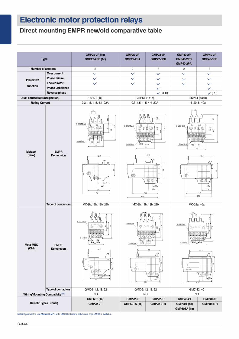
Electronic motor protection relays Direct mounting EMPR new/old comparative table
GMP60T (1c) GMP22-2T GMP22-3T GMP40-2T GMP40-3TRetrofit Type (Tunnel) GMP22-2T GMP60TA (1c) GMP22-3TR GMP60T (1c) GMP40-3TR
GMP60TA (1c)
Protective
function
Metasol(New)
EMPRDemension
Meta-MEC(Old)
EMPRDemension
Type of contactors MC-9b, 12b, 18b, 22b MC-9b, 12b, 18b, 22b MC-32a, 40a
Type of contactors GMC-9, 12, 18, 22 GMC-9, 12, 18, 22 GMC-32, 40
NO NO NOWiring/Mounting CompatibityNote)
GMP22-2P (1c) GMP22-2P GMP22-3P GMP40-2P GMP40-3PGMP22-2PD (1c) GMP22-2PA GMP22-3PR GMP40-2PD GMP40-3PR
GMP40-2PA
Number of sensors 2 2 3 2 3
(PR) (PR)
Aux. contact (at Energization) 1SPDT (1c) 2SPST (1a1b) 2SPST (1a1b)
Rating Current 0.3~1.5, 1~5, 4.4~22A 0.3~1.5, 1~5, 4.4~22A 4~20, 8~40A
Over current
Phase failure
Locked rotor
Phase unbalance
Reverse phase
Note) If you want to use Metasol EMPR with GMC Contactors, only tunnel type EMPR is avaliable.
Type
