electronic motor protection relays...gmp60t gmp60te gmp60ta. electronic motor protection relays...
TRANSCRIPT

Electronic motor protection relays Dimensions GMP Series
30
Screw
Screw
Screw
Screw
Screw
Screw
0.15kg
0.18kg
0.20kg/0.22kg
GMP22-2P (1c) Sol
GMP22-2PD (1c) Sol
GMP22-2P (1a1b) Sol
GMP22-3P Sol
GMP22-2PA (1a1b) Sol
GMP22-3PR Sol
GMP40-2P Sol
GMP40-2PD Sol
GMP40-2PA Sol
GMP40-3P Sol
GMP40-3PR Sol
Screw
Screw
Mounting hole
0.42kg/0.46kg
GMP80-2S
GMP80-3S
GMP80-3SR

Dimensions GMP Series
31
Screw
0.14kg/0.16kg
GMP22-2T
GMP22-3T
GMP22-3TR
GMP40-2T
GMP40-3T
GMP40-3TR
Screw
Screw
0.19kg/0.21kg
GMP22-2S
GMP22-3S
GMP22-3SR
GMP40-2S
GMP40-3S
GMP40-3SR
Screw
Screw
0.14kg
GMP60T
GMP60TE
GMP60TA

Electronic motor protection relays Dimensions GMP Series
32
Note) 1. Only for the GMP60-TZR modle.2. Aux. Contacts are operate when power applied.
Terminal arrangement
GMP22-2P (1c)GMP22-2PD (1c)GMP22-2PA (1c)
GMP22-2P (1a1b)GMP22-3PGMP40-2P/3P
GMP22-2/3SGMP40-3/3SGMP80-2/3S
GMP22-2/3TGMP40-2/3T
GMP60-T/TE/TA GMP60-TDGMP60-TDa
GMP60-3TZ, TZRGMP60-3TN, TNRGMP60-3T/3TR
Note)
GMP60-3TZ, TZR
GMP60-3TN, TNR
GMP60-3T, TR
Tunnel type Screw type - Terminal lug sticking
26.8
7422±
0.5
7.2 8.2
55.472.8
10
6175
5.8 47
12.5
55.4
74
R2.5
R2.5
62.25GMP60-TD
GMP60-TDa
0.25kg

Dimensions DMP Series
33
Note) 1. In extension type, the digital EMPR is calibrated with combining the display unit and mainbodyso, please cautious not to combine the display unit and mainbody with different part No.
2. The 07-08 contacts are the ZCT input terminal (Digital EMPR with ground fault function)
DMP�-S
DMP�-SZ
DMP�-Sa
DMP�-SZa
DMP�-S
DMP�-SZ
DMP�-Sa
DMP�-SZa
※Aux. contact wire size : below 8[mm2]※Torque : 0.5N
Mounting dimensions
0.7kg
Panel mounting0.64kg
Panel cutting size
Mounting dimensions

Electronic motor protection relays Dimensions DMP Series
34
Note) 1. In extension type, the digital EMPR is calibrated with combining the display unit and mainbodyso, please cautious not to combine the display unit and mainbody with different part No.
2. The 07-08 contacts are the ZCT input terminal (Digital EMPR with ground fault function)
DMP�-T
DMP�-TZ
DMP�-Ta
DMP�-TZa
DMP�-T
DMP�-TZ
DMP�-Ta
DMP�-TZa
※Wire size to penetrate a CT :below 22[mm2]
0.56kg
Panel mounting0.5kg
Panel cutting size
Mounting dimensions
Mounting dimensions

Dimensions IMP Series
35
Note) The cable should be purchased separately (1m/1.5m/2m/3m).
M4
64
90
26 445617 17
2022
22
U/2/T1 V/4/T2 W/6/T3
90
68
64
109.
3
53.5
∅1721
5
12
121.
3
4.2
82
25
One-Body Type
Separate BOdy Type
Panel mounting
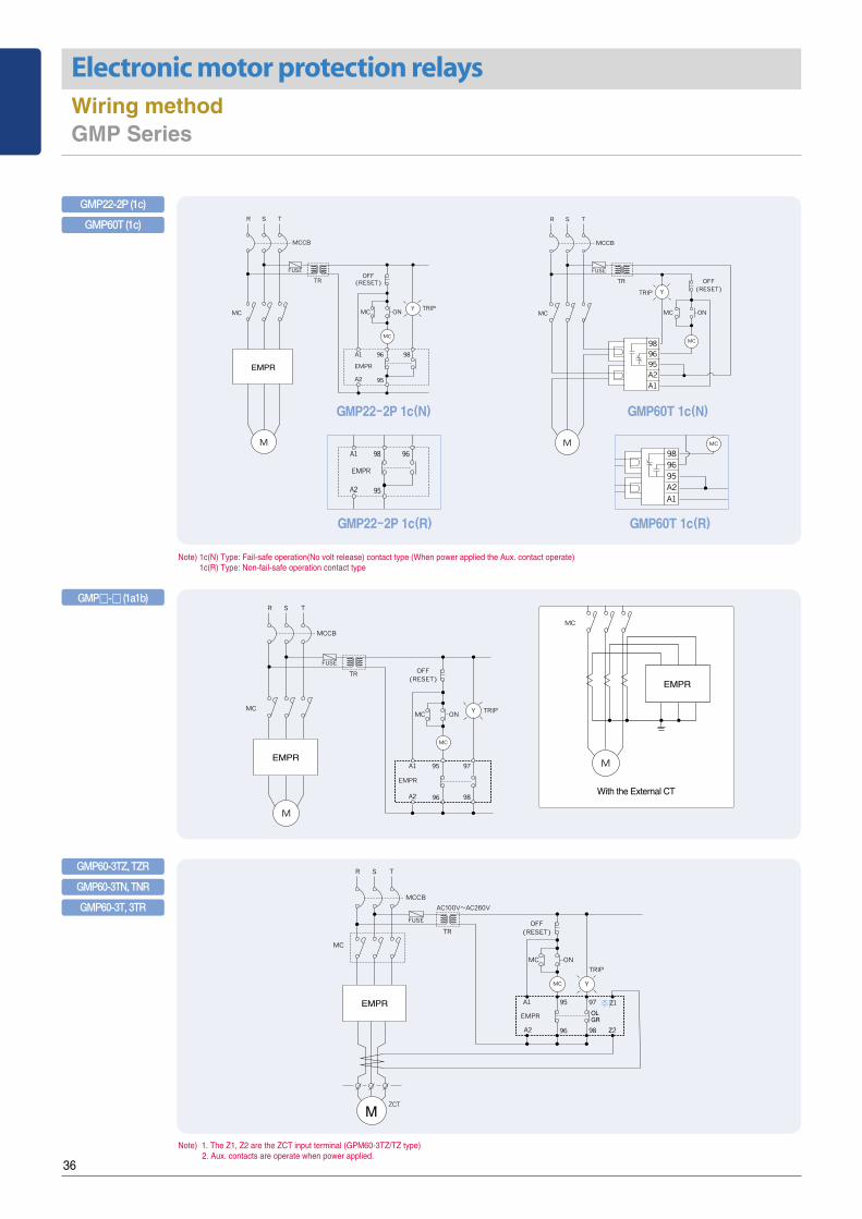
Electronic motor protection relays Wiring method GMP Series
36
Note) 1. The Z1, Z2 are the ZCT input terminal (GPM60-3TZ/TZ type)2. Aux. contacts are operate when power applied.
Note) 1c(N) Type: Fail-safe operation(No volt release) contact type (When power applied the Aux. contact operate)1c(R) Type: Non-fail-safe operation contact type
With the External CT
주)
GMP22-2P (1c)
GMP�-� (1a1b)
GMP60T (1c)
GMP60-3TZ, TZR
GMP60-3TN, TNR
GMP60-3T, 3TR
GMP22-2P 1c(N)
GMP22-2P 1c(R)
GMP60T 1c(N)
GMP60T 1c(R)

Wiring method DMP Series
37
DMP-S/Sa
DMP-T/Ta
With the External CT
Single phase
DMP-SZ/SZa
DMP-TZ/TZa
DMP-SI/TI
(2a)
DMP-TZ/TZa
Note) When the single-phase motor is used, reverse phases protection should be set off.
SR
MC
RUNSTOP
MCCBAUX
MCCBSHUNT
96 98 08
95 97 07
(1a1b) (2b)
96 98
95 97

Electronic motor protection relays Wiring method IMP Series
38
10A
100A
96 97 98 07 08 Z1 Z2
VT TRX(+) 05 06TRX(-)
ZCTA1 A2 95 96(+) (-)
VR VS VT
Note) 1. When the zero-phase-sequence current transformer is used to detect ground faults, connect the ZCT.2. When the single-phase motor is used, all phases are connected except the S phase, and open-phase, unbalance and ground fault should be set OFF.
Note) 1. The 3-phase voltage input terminal and 05-06 output terminal should be connected only for voltage protection models, which will be released in the future.2. For RS485 connection, the terminal resistance should be 120Ϊ .3. For 4~20mA current, the maximum burden should be less than 500Ϊ .
Engrave Description Remark
A1(+), A2(-) Input terminal for operation power AC/DC 85~245V, AC/DC 24~36V
95-96 When the power is ON (NC contact output) In case of an instantaneous trip, if 17.lo is ALT, it is NC, and if 17.lo is Trip, it is NO.
97-98 When the power is ON (NC contact output) In case of an instantaneous trip, regardless of 17 .1o setup, it is NC.
07-08 Converted to the NC mode only when an instantaneous trip occurs.
Z1, Z2 Output terminal for the zero-phase sequence current transformer Specific ZCT (for the EMPR)
TRX(+) RS485 terminal (TRX+) Or 4~20mA (+) outputM485, A420 Type
TRX(-) RS485 terminal (TRX-) Or 4~20mA (-) output
10A/100A Max. rated current change S/W 10A : 0.5~10A, 100A : 5~100A
VR/VS/VT 3-phase voltage input terminalN/A
05-06 Output terminal for voltage protection
10A
100A
96 97 98 07 08 Z1 Z2
VT TRX(+) 05 06TRX(-)
ZCTA1 A2 95 96(+) (-)
VR VS VT
ZCT
MC
OLTRIP
MCCBAUX
MCCB
RS485(4~20mA)
OFF(RESET)
SHT
Y
MC
A1 A2 95 97 07
Z1
TRX (+, -)
OLEMPR
96 98 08 Z2
SR
10A
100A
96 97 98 07 08 Z1 Z2
VT TRX(+) 05 06TRX(-)
ZCTA1 A2 95 96(+) (-)
VR VS VT
With the External CTNote 1)
Terminal Configuration
Terminal layout Communication specification
- Operation mode: Differential
- Distance: Max. 1.2km
- General RS-485 shielded twist 2-pair cable
- Baud rate: 9600/19200/38400bps
- Transmission method: half-Duplex
- Max. In/Output voltage: -7V~+12V