electromechanical matrix fully integrated … · passive inter-modulation (pim) test stands,...
TRANSCRIPT
SWITCHSOLUTIONS
ELECTROMECHANICAL MATRIX
SOLID STATE MATRIX
FIBER OPTIC MATRIX
FULLY INTEGRATED SYSTEMS
SWITCH MATRIX CATALOG
OUR EXPERTISE, YOUR SWITCH SOLUTION SINCE 1945

SWITCHMATRICES
Our ExperienceAs the world’s largest manufacturer of electromechanical switches, Dow-Key Microwave Corporation is committed to providing unparalleled customer service, competitive pricing, on-time delivery, and products that are distinguished by quality and reliability. Founded in 1945, we are the oldest continuously operating switch manufacturer in the United States. Today, we are part of Microwave Products Group, a subsidiary of Dover Corporation. Dover is a multi-billion dollar, NYSE-traded, diversified manufacturer of a wide range of proprietary electronic components and systems.
Quality AssuranceDow-Key Microwave is a world-class manufacturer with an unparalleled reputation for product quality. Indeed, our space-qualified switches have contributed to the mission success of nearly 100 satellite and launch vehicle programs since 1972. Our commitment to continuous improvement of our products and processes, along with our extensive series of internal and external assessments, ensures compliance with the AS9100 and ISO-9001:2000 standards requirements.
Advanced CapabilitiesDow-Key Microwave’s 36,000-square-foot, state-of-the-art manufacturing facility includes two Class 7 clean rooms in order to support our high-reliability space and military projects. To accomplish the engineering, manufacture, and test of our products and assemblies, we invest heavily in capital equipment. This advanced equipment includes a wide array of vector network analyzers and synthesized sources, noise figure measuring equipment, passive inter-modulation (PIM) test stands, thermal/vacuum chambers, RF power sources, and shock and vibration stations for environmental screening, to name just a few.
Your Switch SolutionThe best in the RF switch industry, Dow-Key Microwave’s engineering team is dedicated to supporting customers through product selection, custom-designed solutions, and RF system integration. Whether your organization needs electromechanical switches, automated test equipment, or space-qualified switching arrays, our engineering team works with your specific requirements to create the optimum RF switching solution. Backed by decades of industry experience, our highly skilled technical staff is continuously improving the quality and variety of our product offering based upon customer needs as well as advances in technology. We offer customers the best value solution for their applications, on budget and on time. Since 1945, our experience is your switch solution.
Rev. 0913
TABLE OF CONTENTS
Description PageOrdering Information i
Electromechanical Switch Matrices 1-1
MS-Series Multiple Switches 1-2
MS-Controller Build Your Own Solution 1-5
MS-Control Kit Build Your Own Solution 1-7
MP-Series Multiplexer 1-8
CB-Series Crossbar 1-10
Model 4141 2x32 Crossbar 1-12
Model 4169 10x10 Phase Matched Crossbar 1-13
Model 4601 4x4 to 8x8 Fan-Out 1-14
Model 4701 9x9 to 12x12 Fan-Out 1-15
Solid State Switch Matrices 2-1
Model 3202 L-band Fan-Out 2-2
Model 3203 VHF-band Fan-Out 2-3
Model 3204 IF-band Fan-Out 2-4
Model 3205 HF-band Fan-Out 2-5
Fiber Optic Switch Matrices 3-1
7001 8x14 C-band Crossbar with partial Fan-Out 3-2
7002 14x15 C-band Crossbar with partial Fan-Out 3-3
Switch System Capabilities - Integrated Systems 4-1
5096 16x32 expandable to 32x64 C-Band Fan-Out 4-2
5190/5191 12x48 Transmitter / 48x12 Receiver L-band 4-3
5230 4x48 /48x2 L-Band Fan-In/Fan-Out 4-4
Appendix - RF Data & Schematics 5-1
Appendix A Determine Enclosure Height 5-2
Appendix B MP-Series RF Data 5-3
Appendix C Switch Schematics 5-4
At Dow-Key you are not limited to the products in this catalog, as it is intended to be used as a guide in selecting a switch product or switch matrix for a given application. Requests for modification of standard items and their specifications in order to meet specific needs are always welcome. Inquiries regarding custom integrated components or switch assemblies are also always appreciated.
The catalog is subject to change without notification at any time and new product information is constantly being added in the form of press releases through the corporate website at www.dowkey.com. Please visit our website to request quotes, download product materials, for listing of our manufacturer’s representative and factory contact information.
OrderingThe information found in this catalog or on www.dowkey.com should be sufficient for you to select a particular Dow-Key product. In those cases where additional information is required, call Dow-Key directly or our local Dow-Key Sales Representative who will provide you with price and delivery information.
When placing your order, please include the part number, product name, quantity, and shipping instructions. In the case of a non-standard product, a full description of desired features must accompany your order to avoid any errors. Send orders to:
Dow-Key Microwave4822 McGrath StreetVentura, CA 93003 U.S.A.
Or send them in care of our Sales Representative in your area. A complete listing of our Representatives can be found at www.dowkey.com.
Orders will be accepted by way of U.S. mail, telephone, fax, or email. Confirmation of orders on your standard Purchase Order is required.
Telephone: 805.650.0260Fax: 805.650.1734Email: [email protected]
Domestic TermsNet 30 days, F.O.B. Dow-Key plant, Ventura, California, U.S.A. unless otherwise specified. Shipments made to firms are on a C.O.D. basis unless credit has been established or on receipt of advance payment. American Express, MasterCard and Visa are also accepted.
Export TermsUnless other terms have been agreed upon in advance, export terms are either payment in advance of shipment or against a confirmed irrevocable letter of credit. All prices are F.O.B Ventura, California, U.S.A.
ShippingOrders within the United States and Canada will be shipped via United Parcel Service Ground unless other instructions are received. Shipment to all other countries will be by customer direction.
PackagingAll products shipped from Dow-Key Microwave, Ventura, California are packaged in accordance with best commercial practices unless otherwise specified in the contract or purchase order.
DeliveryMost standard products are available from within our typical manufacturing lead-time of 4 to 12 weeks after receipt of order.
ORDERING INFORMATION
Source InspectionShould Customer Source Inspection of product be required, a charge of $300.00 per day per occurrence will apply.
Application and Technical AssistanceDow-Key provides a knowledgeable and experienced engineering staff to work closely with customers in product design and application development as well as minor modifications to existing standard products. This service is also available for the design of individual specialized switching components or complex switching systems.
WarrantyDow-Key Microwave Corporation warrants all switch products to be free of defects in material and workmanship for a period of one year after the date of initial shipment. The limit of liability under this warranty is to repair, replace or refund purchase price on any product or part thereof that is returned by the purchaser and proves to be defective after examination by Dow-Key. This warranty does not extend to any products mishandled, misused or subjected to abuse or neglect in storage, transportation or use. Repairs or alterations made without consent or knowledge of Dow-Key Microwave Corporation will invalidate this warranty. This warranty supercedes all others, either expressed or implied.
Return Material AuthorizationPlease contact Dow-Key to receive a Return Material Authorization (RMA) number prior to returning any item for service. Items returned to Dow-Key without a RMA number are subject to return without evaluation or any work being done. Dow Key will not accept COD freight charges for returned items.
Dow-Key Terms and ConditionsDow-Key Microwave Corporation Terms and Conditions apply to all orders unless other provisions have been previously agreed upon. A copy of Dow-Key’s Terms and Conditions can be found at www.dowkey.com.
Certificate of ComplianceIf requested at order placement, a certificate of compliance is available upon shipment.
Minimum Order AmountDow-Key’s minimum order amount is $300.00.
Product ChangesDow-Key Microwave Corporation continuously improves products as new technologies, materials and processes become available. We, therefore, reserve the right to alter, amend, discontinue, or replace any product and or specifications in this catalog at our sole discretion without prior notice. Jano_FSC Logo
Horizontal Format
FPOMinimum size is 11mm tall
AS9100/ISO-9001: 2008 Certified Dow-Key Microwave • www.dowkey.com • 800.266.3695 iDow-Key Microwave • www.dowkey.com • 800.266.3695 AS9100/ISO-9001: 2008 Certified
For our other product lines, see seperate Product Catalog and Space Product Brouchure for more details.

ELECTROMECHANICALSWITCH MATRICES
AS9100/ISO-9001: 2008 Certified Dow-Key Microwave • www.dowkey.com • 800.266.3695
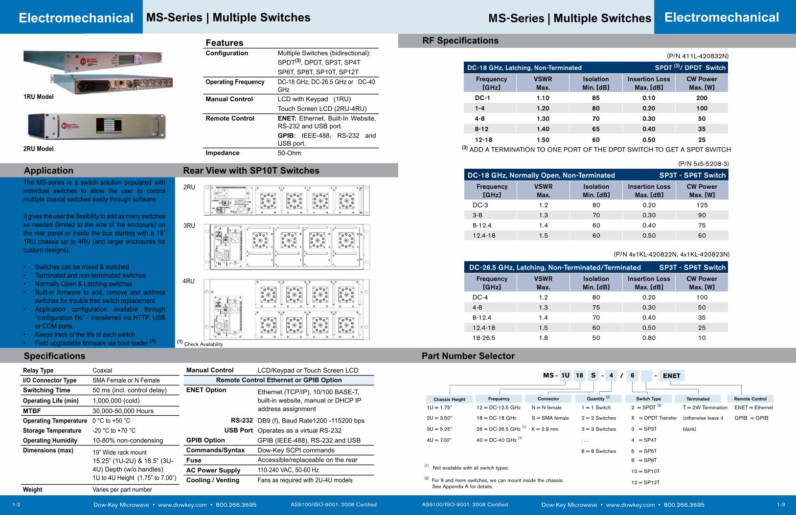
MS-Series | Multiple Switches
1-3
Electromechanical
DC-18 GHz, Normally Open, Non-Terminated SP3T - SP6T Switch
Frequency [GHz]
VSWRMax.
Isolation Min. [dB]
Insertion Loss Max. [dB]
CW Power Max. [W]
DC-3 1.2 80 0.20 125
3-8 1.3 70 0.30 90
8-12.4 1.4 60 0.40 75
12.4-18 1.5 60 0.50 60
DC-26.5 GHz, Latching, Non-Terminated/Terminated SP3T - SP6T Switch
Frequency [GHz]
VSWRMax.
Isolation Min. [dB]
Insertion Loss Max. [dB]
CW Power Max. [W]
DC-4 1.2 80 0.20 100
4-8 1.3 75 0.30 50
8-12.4 1.4 70 0.40 35
12.4-18 1.5 60 0.50 25
18-26.5 1.8 50 0.80 10
DC-18 GHz, Latching, Non-Terminated SPDT (3)/ DPDT Switch
Frequency [GHz]
VSWRMax.
Isolation Min. [dB]
Insertion Loss Max. [dB]
CW Power Max. [W]
DC-1 1.10 85 0.10 200
1-4 1.20 80 0.20 100
4-8 1.30 70 0.30 50
8-12 1.40 65 0.40 35
12-18 1.50 60 0.50 25
Part Number Selector
1U 18 S 4 6MS
1U = 1.75” 12 = DC-12.5 GHz N = N female 1 = 1 Switch 2 = SPDT (3) T = 2W Termination ENET = Ethernet
2U = 3.50” 18 = DC-18 GHz S = SMA female 2 = 2 Switches X = DPDT Transfer (otherwise leave it GPIB = GPIB
3U = 5.25” 26 = DC-26.5 GHz (1) K = 2.9 mm 3 = 3 Switches 3 = SP3T blank)
4U = 7.00” 40 = DC-40 GHz (1) . . . 4 = SP4T
8 = 8 Switches 6 = SP6T
8 = SP8T
10 = SP10T
12 = SP12T
ENET
Chassis Height Frequency Connector Quantity (2) Switch Type Terminated
/
Remote Control
(1) Not available with all switch types.
RF Specifications
Dow-Key Microwave • www.dowkey.com • 800.266.3695 AS9100/ISO-9001: 2008 Certified
MS-Series | Multiple Switches
1-2
Electromechanical
The MS-series is a switch solution populated with individual switches to allow the user to control multiple coaxial switches easily through software.
It gives the user the flexibility to add as many switches as needed (limited to the size of the enclosure) on the rear panel or inside the box starting with a 19” 1RU chassis up to 4RU (and larger enclosures for custom designs).
Switches can be mixed & matched• Terminated and non-terminated switches• Normally Open & Latching switches• Built-in firmware to add, remove and address • switches for trouble free switch replacementApplication configuration available through • “configuration file” - transferred via HTTP, USB or COM ports.Keeps track of the life of each switch• Field upgradable firmware via boot loader • (1)
FeaturesConfiguration Multiple Switches (bidirectional):
SPDT(3), DPDT, SP3T, SP4TSP6T, SP8T, SP10T, SP12T
Operating Frequency DC-18 GHz, DC-26.5 GHz or DC-40 GHz
Manual Control LCD with Keypad (1RU)Touch Screen LCD (2RU-4RU)
Remote Control ENET: Ethernet, Built-In Website, RS-232 and USB port.GPIB: IEEE-488, RS-232 and USB port.
Impedance 50-Ohm
Specifications
Application Rear View with SP10T Switches
1RU Model
2RU Model
2RU
3RU
4RU
Relay Type Coaxial Manual Control LCD/Keypad or Touch Screen LCDI/O Connector Type SMA Female or N Female Remote Control Ethernet or GPIB OptionSwitching Time 50 ms (incl. control delay) ENET Option Ethernet (TCP/IP), 10/100 BASE-T,
built-in website, manual or DHCP IP address assignment
Operating Life (min) 1,000,000 (cold)MTBF 30,000-50,000 HoursOperating Temperature 0 °C to +50 °C RS-232 DB9 (f), Baud Rate1200 -115200 bpsStorage Temperature -20 °C to +70 °C USB Port Operates as a virtual RS-232Operating Humidity 10-80% non-condensing GPIB Option GPIB (IEEE-488), RS-232 and USBDimensions (max) 19” Wide rack mount
15.25” (1U-2U) & 18.5” (3U-4U) Depth (w/o handles)1U to 4U Height (1.75” to 7.00”)
Commands/Syntax Dow-Key SCPI commands Fuse Accessible/replaceable on the rearAC Power Supply 110-240 VAC, 50-60 Hz Cooling / Venting Fans as required with 2U-4U models
Weight Varies per part number
(1) Check Availability
(3) ADD A TERMINATION TO ONE PORT OF THE DPDT SWITCH TO GET A SPDT SWITCH
(2) For 9 and more switches, we can mount inside the chassis. See Appendix A for details.
(P/N 411L-420832N)
(P/N 5x5-5208-3)
(P/N 4x1KL-420822N, 4x1KL-420823N)
AS9100/ISO-9001: 2008 Certified Dow-Key Microwave • www.dowkey.com • 800.266.3695
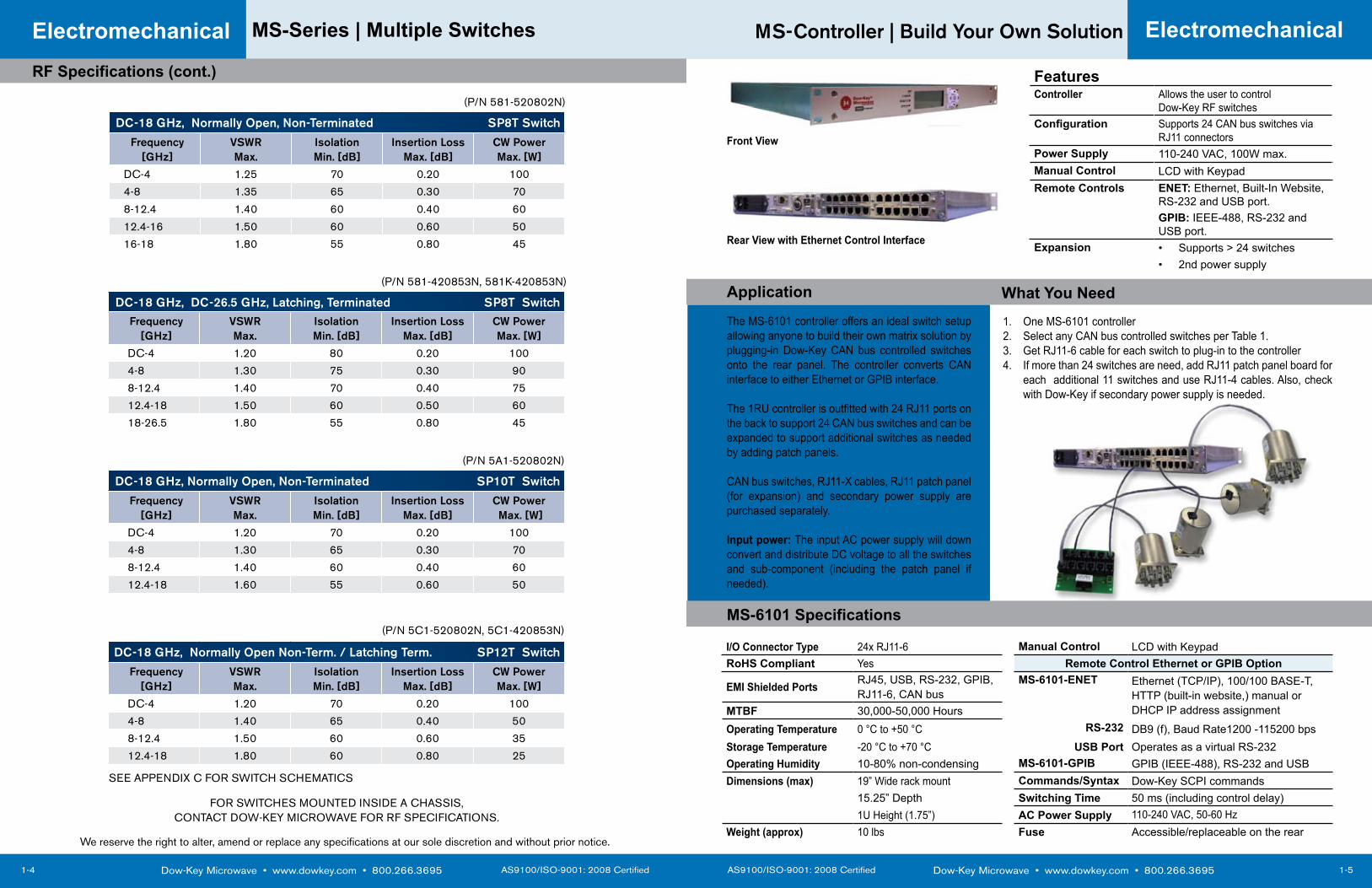
MS-Controller | Build Your Own Solution
1-5
MS-6101 Specifications
Application What You NeedThe MS-6101 controller offers an ideal switch setup allowing anyone to build their own matrix solution by plugging-in Dow-Key CAN bus controlled switches onto the rear panel. The controller converts CAN interface to either Ethernet or GPIB interface.
The 1RU controller is outfitted with 24 RJ11 ports on the back to support 24 CAN bus switches and can be expanded to support additional switches as needed by adding patch panels.
CAN bus switches, RJ11-X cables, RJ11 patch panel (for expansion) and secondary power supply are purchased separately.
Input power: The input AC power supply will down convert and distribute DC voltage to all the switches and sub-component (including the patch panel if needed).
Electromechanical
Dow-Key Microwave • www.dowkey.com • 800.266.3695 AS9100/ISO-9001: 2008 Certified
MS-Series | Multiple Switches
1-4
Electromechanical
DC-18 GHz, Normally Open, Non-Terminated SP10T Switch
Frequency [GHz]
VSWRMax.
Isolation Min. [dB]
Insertion Loss Max. [dB]
CW Power Max. [W]
DC-4 1.20 70 0.20 100
4-8 1.30 65 0.30 70
8-12.4 1.40 60 0.40 60
12.4-18 1.60 55 0.60 50
DC-18 GHz, Normally Open Non-Term. / Latching Term. SP12T Switch
Frequency [GHz]
VSWRMax.
Isolation Min. [dB]
Insertion Loss Max. [dB]
CW Power Max. [W]
DC-4 1.20 70 0.20 100
4-8 1.40 65 0.40 50
8-12.4 1.50 60 0.60 35
12.4-18 1.80 60 0.80 25
DC-18 GHz, Normally Open, Non-Terminated SP8T Switch
Frequency [GHz]
VSWRMax.
Isolation Min. [dB]
Insertion Loss Max. [dB]
CW Power Max. [W]
DC-4 1.25 70 0.20 100
4-8 1.35 65 0.30 70
8-12.4 1.40 60 0.40 60
12.4-16 1.50 60 0.60 50
16-18 1.80 55 0.80 45
DC-18 GHz, DC-26.5 GHz, Latching, Terminated SP8T SwitchFrequency
[GHz]VSWRMax.
Isolation Min. [dB]
Insertion Loss Max. [dB]
CW Power Max. [W]
DC-4 1.20 80 0.20 100
4-8 1.30 75 0.30 90
8-12.4 1.40 70 0.40 75
12.4-18 1.50 60 0.50 60
18-26.5 1.80 55 0.80 45
I/O Connector Type 24x RJ11-6 Manual Control LCD with KeypadRoHS Compliant Yes Remote Control Ethernet or GPIB Option
EMI Shielded Ports RJ45, USB, RS-232, GPIB, RJ11-6, CAN bus
MS-6101-ENET Ethernet (TCP/IP), 100/100 BASE-T, HTTP (built-in website,) manual or DHCP IP address assignmentMTBF 30,000-50,000 Hours
Operating Temperature 0 °C to +50 °C RS-232 DB9 (f), Baud Rate1200 -115200 bpsStorage Temperature -20 °C to +70 °C USB Port Operates as a virtual RS-232Operating Humidity 10-80% non-condensing MS-6101-GPIB GPIB (IEEE-488), RS-232 and USBDimensions (max) 19” Wide rack mount Commands/Syntax Dow-Key SCPI commands
15.25” Depth Switching Time 50 ms (including control delay)1U Height (1.75”) AC Power Supply 110-240 VAC, 50-60 Hz
Weight (approx) 10 lbs Fuse Accessible/replaceable on the rear
Front View
Rear View with Ethernet Control Interface
FeaturesController Allows the user to control
Dow-Key RF switchesConfiguration Supports 24 CAN bus switches via
RJ11 connectorsPower Supply 110-240 VAC, 100W max.Manual Control LCD with Keypad Remote Controls ENET: Ethernet, Built-In Website,
RS-232 and USB port.GPIB: IEEE-488, RS-232 and USB port.
Expansion Supports > 24 switches• 2nd power supply•
One MS-6101 controller1. Select any CAN bus controlled switches per Table 1.2. Get RJ11-6 cable for each switch to plug-in to the controller3. If more than 24 switches are need, add RJ11 patch panel board for 4. each additional 11 switches and use RJ11-4 cables. Also, check with Dow-Key if secondary power supply is needed.
RF Specifications (cont.)
FOR SWITCHES MOUNTED INSIDE A CHASSIS, CONTACT DOW-KEY MICROWAVE FOR RF SPECIFICATIONS.
(P/N 581-520802N)
(P/N 581-420853N, 581K-420853N)
(P/N 5A1-520802N)
(P/N 5C1-520802N, 5C1-420853N)
We reserve the right to alter, amend or replace any specifications at our sole discretion and without prior notice.
SEE APPENDIX C FOR SWITCH SCHEMATICS
AS9100/ISO-9001: 2008 Certified Dow-Key Microwave • www.dowkey.com • 800.266.3695
MS-Control Kit | Build Your Own Solution
1-7
Specifications / Part Numbers
Application / What you Need
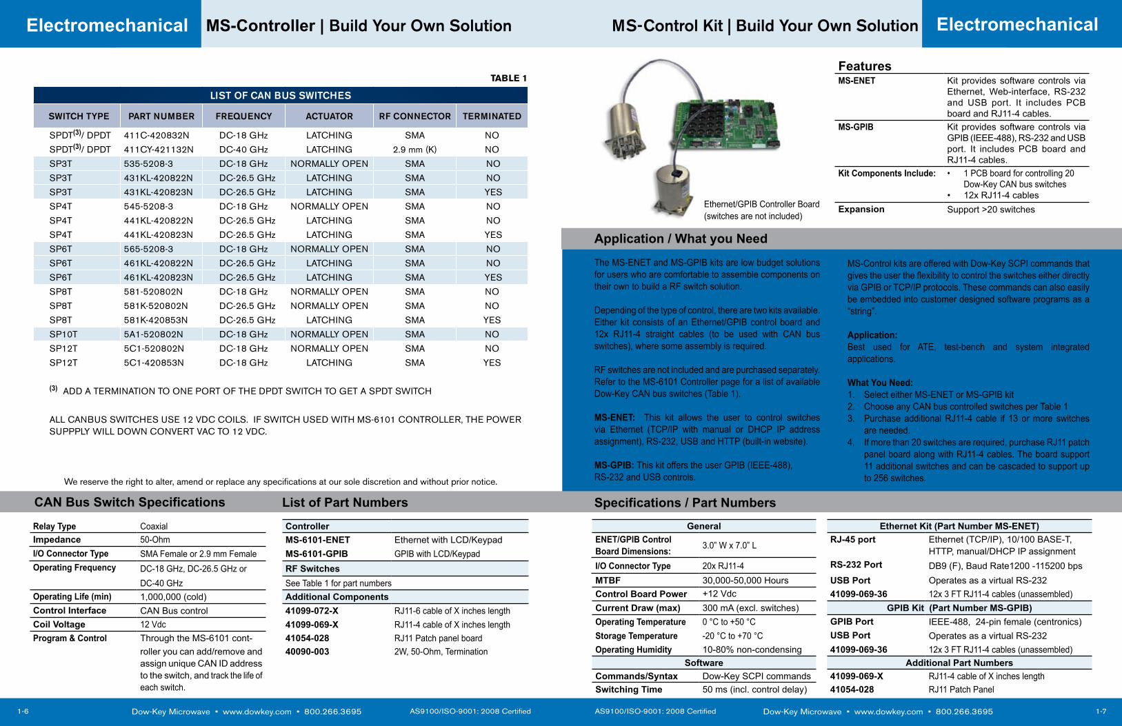
The MS-ENET and MS-GPIB kits are low budget solutions for users who are comfortable to assemble components on their own to build a RF switch solution.
Depending of the type of control, there are two kits available. Either kit consists of an Ethernet/GPIB control board and 12x RJ11-4 straight cables (to be used with CAN bus switches), where some assembly is required.
RF switches are not included and are purchased separately. Refer to the MS-6101 Controller page for a list of available Dow-Key CAN bus switches (Table 1).
MS-ENET: This kit allows the user to control switches via Ethernet (TCP/IP with manual or DHCP IP address assignment), RS-232, USB and HTTP (built-in website).
MS-GPIB: This kit offers the user GPIB (IEEE-488), RS-232 and USB controls.
Electromechanical
Dow-Key Microwave • www.dowkey.com • 800.266.3695 AS9100/ISO-9001: 2008 Certified
MS-Controller | Build Your Own Solution
1-6
Electromechanical
LIST OF CAN BUS SWITCHES
SWITCH TYPE PART NUMBER FREQUENCY ACTUATOR RF CONNECTOR TERMINATED
SPDT(3)/ DPDT 411C-420832N DC-18 GHz LATCHING SMA NO
SPDT(3)/ DPDT 411CY-421132N DC-40 GHz LATCHING 2.9 mm (K) NO
SP3T 535-5208-3 DC-18 GHz NORMALLY OPEN SMA NO
SP3T 431KL-420822N DC-26.5 GHz LATCHING SMA NO
SP3T 431KL-420823N DC-26.5 GHz LATCHING SMA YES
SP4T 545-5208-3 DC-18 GHz NORMALLY OPEN SMA NO
SP4T 441KL-420822N DC-26.5 GHz LATCHING SMA NO
SP4T 441KL-420823N DC-26.5 GHz LATCHING SMA YES
SP6T 565-5208-3 DC-18 GHz NORMALLY OPEN SMA NO
SP6T 461KL-420822N DC-26.5 GHz LATCHING SMA NO
SP6T 461KL-420823N DC-26.5 GHz LATCHING SMA YES
SP8T 581-520802N DC-18 GHz NORMALLY OPEN SMA NO
SP8T 581K-520802N DC-26.5 GHz NORMALLY OPEN SMA NO
SP8T 581K-420853N DC-26.5 GHz LATCHING SMA YES
SP10T 5A1-520802N DC-18 GHz NORMALLY OPEN SMA NO
SP12T 5C1-520802N DC-18 GHz NORMALLY OPEN SMA NO
SP12T 5C1-420853N DC-18 GHz LATCHING SMA YES
(3) ADD A TERMINATION TO ONE PORT OF THE DPDT SWITCH TO GET A SPDT SWITCH
ALL CANBUS SWITCHES USE 12 VDC COILS. IF SWITCH USED WITH MS-6101 CONTROLLER, THE POWER SUPPPLY WILL DOWN CONVERT VAC TO 12 VDC.
FeaturesMS-ENET Kit provides software controls via
Ethernet, Web-interface, RS-232 and USB port. It includes PCB board and RJ11-4 cables.
MS-GPIB Kit provides software controls via GPIB (IEEE-488), RS-232 and USB port. It includes PCB board and RJ11-4 cables.
Kit Components Include: 1 PCB board for controlling 20 • Dow-Key CAN bus switches12x RJ11-4 cables•
Expansion Support >20 switches
General Ethernet Kit (Part Number MS-ENET)ENET/GPIB Control Board Dimensions: 3.0” W x 7.0” L RJ-45 port Ethernet (TCP/IP), 10/100 BASE-T,
HTTP, manual/DHCP IP assignmentI/O Connector Type 20x RJ11-4 RS-232 Port DB9 (F), Baud Rate1200 -115200 bpsMTBF 30,000-50,000 Hours USB Port Operates as a virtual RS-232Control Board Power +12 Vdc 41099-069-36 12x 3 FT RJ11-4 cables (unassembled)Current Draw (max) 300 mA (excl. switches) GPIB Kit (Part Number MS-GPIB)Operating Temperature 0 °C to +50 °C GPIB Port IEEE-488, 24-pin female (centronics)Storage Temperature -20 °C to +70 °C USB Port Operates as a virtual RS-232Operating Humidity 10-80% non-condensing 41099-069-36 12x 3 FT RJ11-4 cables (unassembled)
Software Additional Part NumbersCommands/Syntax Dow-Key SCPI commands 41099-069-X RJ11-4 cable of X inches lengthSwitching Time 50 ms (incl. control delay) 41054-028 RJ11 Patch Panel
CAN Bus Switch Specifications
Relay Type Coaxial ControllerImpedance 50-Ohm MS-6101-ENET Ethernet with LCD/KeypadI/O Connector Type SMA Female or 2.9 mm Female MS-6101-GPIB GPIB with LCD/KeypadOperating Frequency DC-18 GHz, DC-26.5 GHz or RF Switches
DC-40 GHz See Table 1 for part numbersOperating Life (min) 1,000,000 (cold) Additional ComponentsControl Interface CAN Bus control 41099-072-X RJ11-6 cable of X inches lengthCoil Voltage 12 Vdc 41099-069-X RJ11-4 cable of X inches lengthProgram & Control Through the MS-6101 cont- 41054-028 RJ11 Patch panel board
roller you can add/remove and assign unique CAN ID address to the switch, and track the life of each switch.
40090-003 2W, 50-Ohm, Termination
List of Part Numbers
MS-Control kits are offered with Dow-Key SCPI commands that gives the user the flexibility to control the switches either directly via GPIB or TCP/IP protocols. These commands can also easily be embedded into customer designed software programs as a “string”.
Application:Best used for ATE, test-bench and system integrated applications.
What You Need:Select either MS-ENET or MS-GPIB kit1. Choose any CAN bus controlled switches per Table 1 2. Purchase additional RJ11-4 cable if 13 or more switches 3. are needed.If more than 20 switches are required, purchase RJ11 patch 4. panel board along with RJ11-4 cables. The board support 11 additional switches and can be cascaded to support up to 256 switches.
Ethernet/GPIB Controller Board (switches are not included)
TABLE 1
We reserve the right to alter, amend or replace any specifications at our sole discretion and without prior notice.
AS9100/ISO-9001: 2008 Certified Dow-Key Microwave • www.dowkey.com • 800.266.3695
MP-Series | Multiplexer
1-9
Electromechanical
Dow-Key Microwave • www.dowkey.com • 800.266.3695 AS9100/ISO-9001: 2008 Certified
MP-Series | Multiplexer
1-8
Electromechanical
Specifications
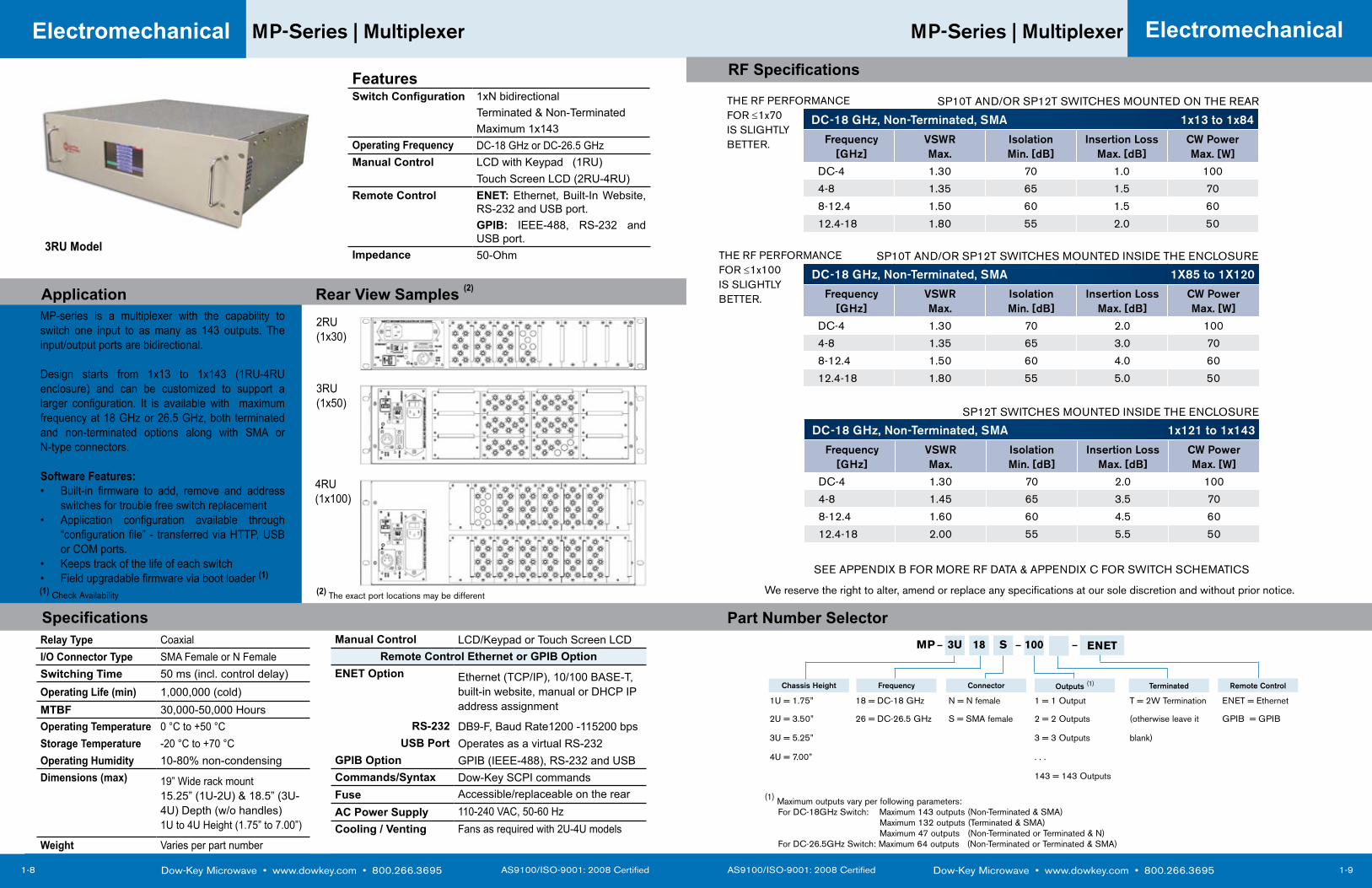
MP-series is a multiplexer with the capability to switch one input to as many as 143 outputs. The input/output ports are bidirectional.
Design starts from 1x13 to 1x143 (1RU-4RU enclosure) and can be customized to support a larger configuration. It is available with maximum frequency at 18 GHz or 26.5 GHz, both terminated and non-terminated options along with SMA or N-type connectors.
Software Features:Built-in firmware to add, remove and address • switches for trouble free switch replacementApplication configuration available through • “configuration file” - transferred via HTTP, USB or COM ports.Keeps track of the life of each switch• Field upgradable firmware via boot loader • (1)
FeaturesSwitch Configuration 1xN bidirectional
Terminated & Non-TerminatedMaximum 1x143
Operating Frequency DC-18 GHz or DC-26.5 GHzManual Control LCD with Keypad (1RU)
Touch Screen LCD (2RU-4RU)Remote Control ENET: Ethernet, Built-In Website,
RS-232 and USB port.GPIB: IEEE-488, RS-232 and USB port.
Impedance 50-Ohm
Application Rear View Samples (2)
2RU(1x30)
3RU(1x50)
4RU(1x100)
DC-18 GHz, Non-Terminated, SMA 1x13 to 1x84
Frequency [GHz]
VSWRMax.
Isolation Min. [dB]
Insertion Loss Max. [dB]
CW Power Max. [W]
DC-4 1.30 70 1.0 100
4-8 1.35 65 1.5 70
8-12.4 1.50 60 1.5 60
12.4-18 1.80 55 2.0 50
Part Number Selector3U 18 S 100MP
1U = 1.75” 18 = DC-18 GHz N = N female 1 = 1 Output T = 2W Termination ENET = Ethernet
2U = 3.50” 26 = DC-26.5 GHz S = SMA female 2 = 2 Outputs (otherwise leave it GPIB = GPIB
3U = 5.25” 3 = 3 Outputs blank)
4U = 7.00” . . .
143 = 143 Outputs
ENET
Chassis Height Frequency Connector Outputs (1) Terminated Remote Control
(1) Maximum outputs vary per following parameters: For DC-18GHz Switch: Maximum 143 outputs (Non-Terminated & SMA) Maximum 132 outputs (Terminated & SMA) Maximum 47 outputs (Non-Terminated or Terminated & N) For DC-26.5GHz Switch: Maximum 64 outputs (Non-Terminated or Terminated & SMA)
RF Specifications
DC-18 GHz, Non-Terminated, SMA 1X85 to 1X120
Frequency [GHz]
VSWRMax.
Isolation Min. [dB]
Insertion Loss Max. [dB]
CW Power Max. [W]
DC-4 1.30 70 2.0 100
4-8 1.35 65 3.0 70
8-12.4 1.50 60 4.0 60
12.4-18 1.80 55 5.0 50
(1) Check Availability
3RU Model
Relay Type Coaxial Manual Control LCD/Keypad or Touch Screen LCDI/O Connector Type SMA Female or N Female Remote Control Ethernet or GPIB OptionSwitching Time 50 ms (incl. control delay) ENET Option Ethernet (TCP/IP), 10/100 BASE-T,
built-in website, manual or DHCP IP address assignment
Operating Life (min) 1,000,000 (cold)MTBF 30,000-50,000 HoursOperating Temperature 0 °C to +50 °C RS-232 DB9-F, Baud Rate1200 -115200 bpsStorage Temperature -20 °C to +70 °C USB Port Operates as a virtual RS-232Operating Humidity 10-80% non-condensing GPIB Option GPIB (IEEE-488), RS-232 and USBDimensions (max) 19” Wide rack mount
15.25” (1U-2U) & 18.5” (3U-4U) Depth (w/o handles)1U to 4U Height (1.75” to 7.00”)
Commands/Syntax Dow-Key SCPI commands Fuse Accessible/replaceable on the rearAC Power Supply 110-240 VAC, 50-60 Hz Cooling / Venting Fans as required with 2U-4U models
Weight Varies per part number
(2) The exact port locations may be different
SP10T AND/OR SP12T SWITCHES MOUNTED ON THE REAR
SP10T AND/OR SP12T SWITCHES MOUNTED INSIDE THE ENCLOSURE
DC-18 GHz, Non-Terminated, SMA 1x121 to 1x143
Frequency [GHz]
VSWRMax.
Isolation Min. [dB]
Insertion Loss Max. [dB]
CW Power Max. [W]
DC-4 1.30 70 2.0 100
4-8 1.45 65 3.5 70
8-12.4 1.60 60 4.5 60
12.4-18 2.00 55 5.5 50
SP12T SWITCHES MOUNTED INSIDE THE ENCLOSURE
SEE APPENDIX B FOR MORE RF DATA & APPENDIX C FOR SWITCH SCHEMATICS
We reserve the right to alter, amend or replace any specifications at our sole discretion and without prior notice.
THE RF PERFORMANCEFOR ≤1x70 IS SLIGHTLYBETTER.
THE RF PERFORMANCEFOR ≤1x100 IS SLIGHTLYBETTER.
AS9100/ISO-9001: 2008 Certified Dow-Key Microwave • www.dowkey.com • 800.266.3695
CB-Series | Crossbar
1-11
Part Number Selector
Electromechanical
Dow-Key Microwave • www.dowkey.com • 800.266.3695 AS9100/ISO-9001: 2008 Certified
CB-Series | Crossbar
1-10
Electromechanical
FeaturesSwitch Configuration 2x2 up to 12x12
Terminated & Non-TerminatedConfiguration Non-Blocking CrossbarOperating Frequency DC-18 GHz or DC-26.5 GHzManual Control LCD with Keypad (1RU)
Touch Screen LCD (2RU-4RU)
Remote Control ENET: Ethernet, Built-In Website, RS-232 and USB port.GPIB: IEEE-488, RS-232 and USB port.
Impedance 50-Ohm
CAN Bus Specifications
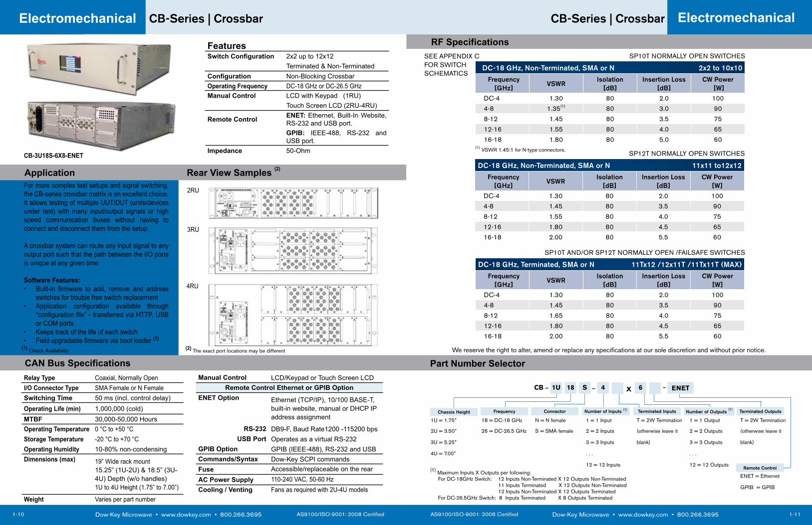
For more complex test setups and signal switching, the CB-series crossbar matrix is an excellent choice. It allows testing of multiple UUT/DUT (units/devices under test) with many input/output signals or high speed communication buses without having to connect and disconnect them from the setup.
A crossbar system can route any input signal to any output port such that the path between the I/O ports is unique at any given time.
Software Features:Built-in firmware to add, remove and address • switches for trouble free switch replacementApplication configuration available through • “configuration file” - transferred via HTTP, USB or COM ports.Keeps track of the life of each switch• Field upgradable firmware via boot loader • (1)
Application Rear View Samples (2)
2RU
3RU
4RU
CB-3U18S-6X8-ENET
Relay Type Coaxial, Normally Open Manual Control LCD/Keypad or Touch Screen LCDI/O Connector Type SMA Female or N Female Remote Control Ethernet or GPIB OptionSwitching Time 50 ms (incl. control delay) ENET Option Ethernet (TCP/IP), 10/100 BASE-T,
built-in website, manual or DHCP IP address assignment
Operating Life (min) 1,000,000 (cold)MTBF 30,000-50,000 HoursOperating Temperature 0 °C to +50 °C RS-232 DB9-F, Baud Rate1200 -115200 bpsStorage Temperature -20 °C to +70 °C USB Port Operates as a virtual RS-232Operating Humidity 10-80% non-condensing GPIB Option GPIB (IEEE-488), RS-232 and USBDimensions (max) 19” Wide rack mount
15.25” (1U-2U) & 18.5” (3U-4U) Depth (w/o handles)1U to 4U Height (1.75” to 7.00”)
Commands/Syntax Dow-Key SCPI commands Fuse Accessible/replaceable on the rearAC Power Supply 110-240 VAC, 50-60 Hz Cooling / Venting Fans as required with 2U-4U models
Weight Varies per part number
DC-18 GHz, Non-Terminated, SMA or N 2x2 to 10x10
Frequency [GHz]
VSWRIsolation
[dB]Insertion Loss
[dB]CW Power
[W]
DC-4 1.30 80 2.0 100
4-8 1.35(1) 80 3.0 90
8-12 1.45 80 3.5 75
12-16 1.55 80 4.0 65
16-18 1.80 80 5.0 60
1U 18 S 4 6CB
1U = 1.75” 18 = DC-18 GHz N = N female 1 = 1 Input T = 2W Termination 1 = 1 Output T = 2W Termination
2U = 3.50” 26 = DC-26.5 GHz S = SMA female 2 = 2 Inputs (otherwise leave it 2 = 2 Outputs (otherwise leave it
3U = 5.25” 3 = 3 Inputs blank) 3 = 3 Outputs blank)
4U = 7.00” . . . . . .
12 = 12 Inputs 12 = 12 Outputs
ENET = Ethernet
GPIB = GPIB
ENET
Chassis Height Frequency Connector Number of Inputs (1) Terminated Inputs Number of Outputs (1)
X
Terminated Outputs
(1) Maximum Inputs X Outputs per following: For DC-18GHz Switch: 12 Inputs Non-Terminated X 12 Outputs Non-Terminated 11 Inputs Terminated X 12 Outputs Non-Terminated 12 Inputs Non-Terminated X 12 Outputs Terminated For DC-26.5GHz Switch: 8 Inputs Terminated X 8 Outputs Terminated
Remote Control
DC-18 GHz, Non-Terminated, SMA or N 11x11 to12x12
Frequency [GHz]
VSWRIsolation
[dB]Insertion Loss
[dB]CW Power
[W]
DC-4 1.30 80 2.0 100
4-8 1.45 80 3.5 90
8-12 1.55 80 4.0 75
12-16 1.80 80 4.5 65
16-18 2.00 80 5.5 60
RF Specifications
(1) Check Availability (2) The exact port locations may be different
SP10T NORMALLY OPEN SWITCHES
SP12T NORMALLY OPEN SWITCHES
We reserve the right to alter, amend or replace any specifications at our sole discretion and without prior notice.
DC-18 GHz, Terminated, SMA or N 11Tx12 /12x11T /11Tx11T (MAX)
Frequency [GHz]
VSWRIsolation
[dB]Insertion Loss
[dB]CW Power
[W]
DC-4 1.30 80 2.0 100
4-8 1.45 80 3.5 90
8-12 1.65 80 4.0 75
12-16 1.80 80 4.5 65
16-18 2.00 80 5.5 60
SP10T AND/OR SP12T NORMALLY OPEN /FAILSAFE SWITCHES
SEE APPENDIX C FOR SWITCH SCHEMATICS
(1) VSWR 1.45:1 for N-type connectors.
AS9100/ISO-9001: 2008 Certified Dow-Key Microwave • www.dowkey.com • 800.266.3695
4169 | Crossbar
1-13
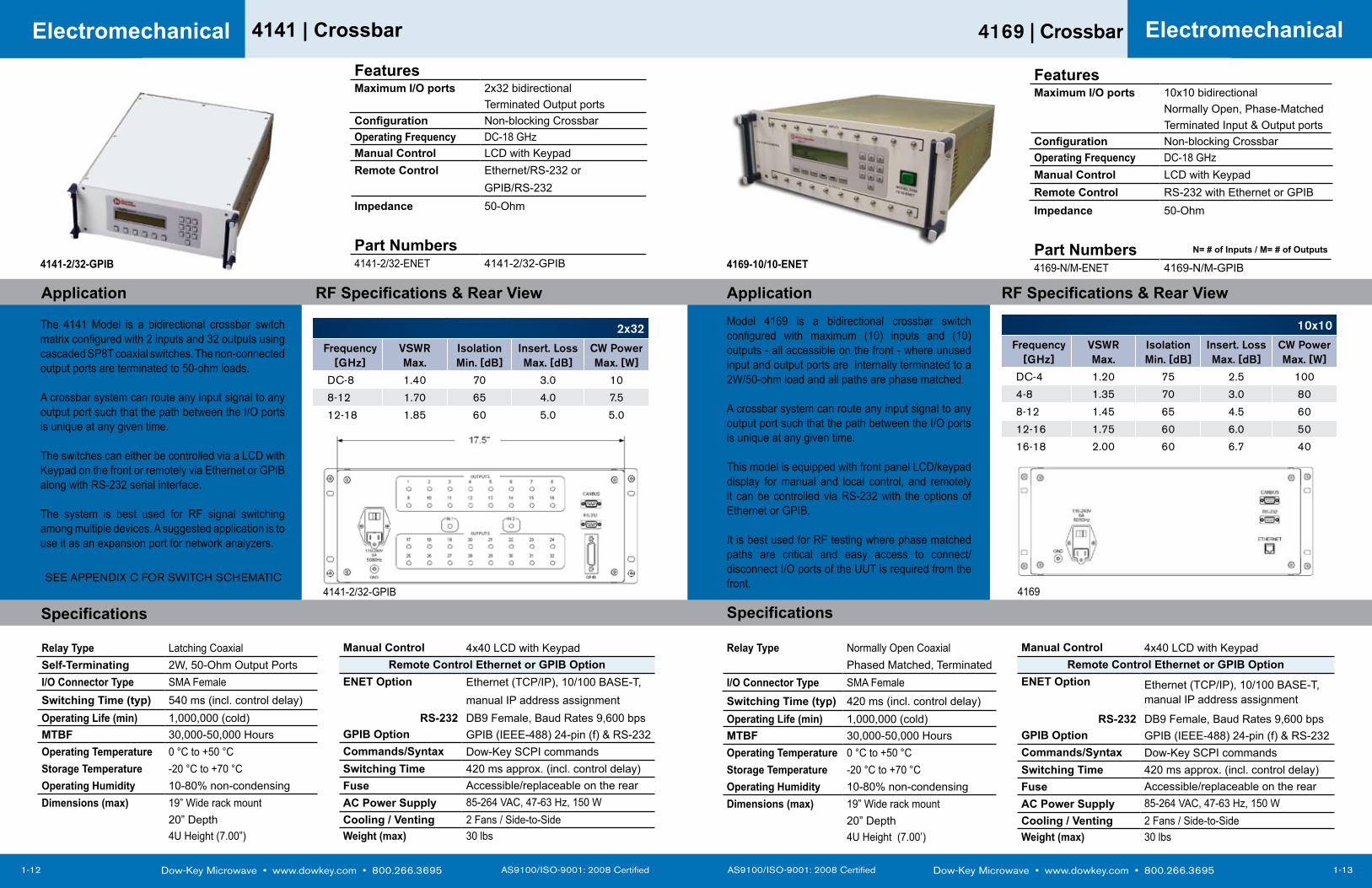
Application RF Specifications & Rear ViewModel 4169 is a bidirectional crossbar switch configured with maximum (10) inputs and (10) outputs - all accessible on the front - where unused input and output ports are internally terminated to a 2W/50-ohm load and all paths are phase matched.
A crossbar system can route any input signal to any output port such that the path between the I/O ports is unique at any given time.
This model is equipped with front panel LCD/keypad display for manual and local control, and remotely it can be controlled via RS-232 with the options of Ethernet or GPIB.
It is best used for RF testing where phase matched paths are critical and easy access to connect/disconnect I/O ports of the UUT is required from the front.
Electromechanical
Dow-Key Microwave • www.dowkey.com • 800.266.3695 AS9100/ISO-9001: 2008 Certified
4141 | Crossbar
1-12
Electromechanical
The 4141 Model is a bidirectional crossbar switch matrix configured with 2 inputs and 32 outputs using cascaded SP8T coaxial switches. The non-connected output ports are terminated to 50-ohm loads.
A crossbar system can route any input signal to any output port such that the path between the I/O ports is unique at any given time.
The switches can either be controlled via a LCD with Keypad on the front or remotely via Ethernet or GPIB along with RS-232 serial interface.
The system is best used for RF signal switching among multiple devices. A suggested application is to use it as an expansion port for network analyzers.
FeaturesMaximum I/O ports 2x32 bidirectional
Terminated Output portsConfiguration Non-blocking CrossbarOperating Frequency DC-18 GHzManual Control LCD with KeypadRemote Control Ethernet/RS-232 or
GPIB/RS-232Impedance 50-Ohm
Part Numbers4141-2/32-ENET 4141-2/32-GPIB
Specifications
Application RF Specifications & Rear View
Relay Type Latching Coaxial Manual Control 4x40 LCD with KeypadSelf-Terminating 2W, 50-Ohm Output Ports Remote Control Ethernet or GPIB OptionI/O Connector Type SMA Female ENET Option Ethernet (TCP/IP), 10/100 BASE-T, Switching Time (typ) 540 ms (incl. control delay) manual IP address assignmentOperating Life (min) 1,000,000 (cold) RS-232 DB9 Female, Baud Rates 9,600 bpsMTBF 30,000-50,000 Hours GPIB Option GPIB (IEEE-488) 24-pin (f) & RS-232 Operating Temperature 0 °C to +50 °C Commands/Syntax Dow-Key SCPI commands Storage Temperature -20 °C to +70 °C Switching Time 420 ms approx. (incl. control delay)Operating Humidity 10-80% non-condensing Fuse Accessible/replaceable on the rearDimensions (max) 19” Wide rack mount AC Power Supply 85-264 VAC, 47-63 Hz, 150 W
20” Depth Cooling / Venting 2 Fans / Side-to-Side4U Height (7.00”) Weight (max) 30 lbs
4141-2/32-GPIB
4141-2/32-GPIB
FeaturesMaximum I/O ports 10x10 bidirectional
Normally Open, Phase-MatchedTerminated Input & Output ports
Configuration Non-blocking CrossbarOperating Frequency DC-18 GHzManual Control LCD with KeypadRemote Control RS-232 with Ethernet or GPIBImpedance 50-Ohm
Part Numbers N= # of Inputs / M= # of Outputs
4169-N/M-ENET 4169-N/M-GPIB4169-10/10-ENET
Relay Type Normally Open Coaxial Manual Control 4x40 LCD with KeypadPhased Matched, Terminated Remote Control Ethernet or GPIB Option
I/O Connector Type SMA Female ENET Option Ethernet (TCP/IP), 10/100 BASE-T, manual IP address assignmentSwitching Time (typ) 420 ms (incl. control delay)
Operating Life (min) 1,000,000 (cold) RS-232 DB9 Female, Baud Rates 9,600 bpsMTBF 30,000-50,000 Hours GPIB Option GPIB (IEEE-488) 24-pin (f) & RS-232 Operating Temperature 0 °C to +50 °C Commands/Syntax Dow-Key SCPI commands Storage Temperature -20 °C to +70 °C Switching Time 420 ms approx. (incl. control delay)Operating Humidity 10-80% non-condensing Fuse Accessible/replaceable on the rearDimensions (max) 19” Wide rack mount AC Power Supply 85-264 VAC, 47-63 Hz, 150 W
20” Depth Cooling / Venting 2 Fans / Side-to-Side4U Height (7.00’) Weight (max) 30 lbs
10x10
Frequency [GHz]
VSWRMax.
Isolation Min. [dB]
Insert. Loss Max. [dB]
CW Power Max. [W]
DC-4 1.20 75 2.5 100
4-8 1.35 70 3.0 80
8-12 1.45 65 4.5 60
12-16 1.75 60 6.0 50
16-18 2.00 60 6.7 40
4169
2x32
Frequency [GHz]
VSWRMax.
Isolation Min. [dB]
Insert. Loss Max. [dB]
CW Power Max. [W]
DC-8 1.40 70 3.0 10
8-12 1.70 65 4.0 7.5
12-18 1.85 60 5.0 5.0
Specifications
SEE APPENDIX C FOR SWITCH SCHEMATIC
AS9100/ISO-9001: 2008 Certified Dow-Key Microwave • www.dowkey.com • 800.266.3695
4701 | Fan-Out
1-15
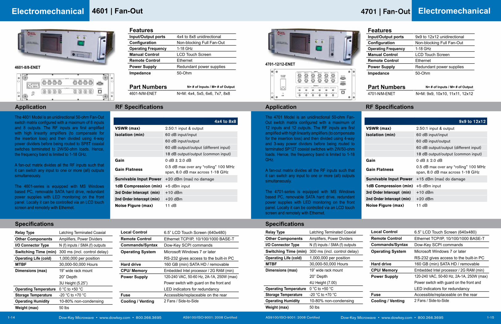
Application RF SpecificationsThe 4701 Model is an unidirectional 50-ohm Fan-Out switch matrix configured with a maximum of 12 inputs and 12 outputs. The RF inputs are first amplified with high linearity amplifiers (to compensate for the insertion loss) and then divided using 4-way and 3-way power dividers before being routed to terminated SP12T coaxial switches with 2W/50-ohm loads. Hence, the frequency band is limited to 1-18 GHz.
A fan-out matrix divides all the RF inputs such that it can switch any input to one or more (all) outputs simultaneously.
The 4701-series is equipped with MS Windows based PC, removable SATA hard drive, redundant power supplies with LED monitoring on the front panel. Locally it can be controlled via an LCD touch screen and remotely with Ethernet.
Electromechanical
Dow-Key Microwave • www.dowkey.com • 800.266.3695 AS9100/ISO-9001: 2008 Certified
4601 | Fan-Out
1-14
Electromechanical
The 4601 Model is an unidirectional 50-ohm Fan-Out switch matrix configured with a maximum of 8 inputs and 8 outputs. The RF inputs are first amplified with high linearity amplifiers (to compensate for the insertion loss) and then divided using 4-way power dividers before being routed to SP8T coaxial switches terminated to 2W/50-ohm loads. Hence, the frequency band is limited to 1-18 GHz.
A fan-out matrix divides all the RF inputs such that it can switch any input to one or more (all) outputs simultaneously.
The 4601-series is equipped with MS Windows based PC, removable SATA hard drive, redundant power supplies with LED monitoring on the front panel. Locally it can be controlled via an LCD touch screen and remotely with Ethernet.
FeaturesInput/Output ports 4x4 to 8x8 unidirectionalConfiguration Non-blocking Full Fan-OutOperating Frequency 1-18 GHzManual Control LCD Touch ScreenRemote Control EthernetPower Supply Redundant power suppliesImpedance 50-Ohm
Part Numbers N= # of Inputs / M= # of Output
4601-N/M-ENET N=M: 4x4, 5x5, 6x6, 7x7, 8x8
Specifications
Application RF Specifications
Relay Type Latching Terminated Coaxial Local Control 6.5” LCD Touch Screen (640x480)Other Components Amplifiers, Power Dividers Remote Control Ethernet TCP/IP, 10/100/1000 BASE-TI/O Connector Type N (f) inputs / SMA (f) outputs Commands/Syntax Dow-Key SCPI commands Switching Time (min) 300 ms (incl. control delay) Operating System Microsoft Windows 7 or laterOperating Life (cold) 1,000,000 per position RS-232 gives access to the built-in PCMTBF 30,000-50,000 Hours Hard drive 160 GB (min) SATA HD / removableDimensions (max) 19” wide rack mount CPU/ Memory Embedded Intel processor / 2G RAM (min)
20” Depth Power Supply 120-240 VAC, 50-60 Hz, 2A-1A, 250W (max) 3U Height (5.25”) Power switch with guard on the front and
Operating Temperature 0 °C to +50 °C LED indicators for redundancyStorage Temperature -20 °C to +70 °C Fuse Accessible/replaceable on the rearOperating Humidity 10-80% non-condensing Cooling / Venting 2 Fans / Side-to-SideWeight (max) 50 lbs
4x4 to 8x8VSWR (max) 2.50:1 input & output
Isolation (min) 60 dB input/input
60 dB input/output
60 dB output/output (different input)
18 dB output/output (common input)
Gain 0 dB ± 2.0 dB
Gain Flatness0.5 dB max over any “rolling” 100 MHz span, 8.0 dB max across 1-18 GHz
Survivable Input Power +20 dBm (max) no damage
1dB Compression (min) +5 dBm input
3rd Order Intercept (min) +10 dBm
2nd Order Intercept (min) +20 dBm
Noise Figure (max) 11 dB
4601-8/8-ENET
9x9 to 12x12VSWR (max) 2.50:1 input & output
Isolation (min) 60 dB input/input
60 dB input/output
60 dB output/output (different input)
18 dB output/output (common input)
Gain 0 dB ± 2.0 dB
Gain Flatness0.5 dB max over any “rolling” 100 MHz span, 8.0 dB max across 1-18 GHz
Survivable Input Power +15 dBm (max) do damage
1dB Compression (min) +5 dBm input
3rd Order Intercept (min) +10 dBm
2nd Order Intercept (min) +20 dBm
Noise Figure (max) 11 dB
FeaturesInput/Output ports 9x9 to 12x12 unidirectionalConfiguration Non-blocking Full Fan-OutOperating Frequency 1-18 GHzManual Control LCD Touch ScreenRemote Control EthernetPower Supply Redundant power suppliesImpedance 50-Ohm
Part Numbers N= # of Inputs / M= # of Output
4701-N/M-ENET N=M: 9x9, 10x10, 11x11, 12x12
4701-12/12-ENET
SpecificationsRelay Type Latching Terminated Coaxial Local Control 6.5” LCD Touch Screen (640x480)Other Components Amplifiers, Power Dividers Remote Control Ethernet TCP/IP, 10/100/1000 BASE-TI/O Connector Type N (f) inputs / SMA (f) outputs Commands/Syntax Dow-Key SCPI commands Switching Time (min) 300 ms (incl. control delay) Operating System Microsoft Windows 7 or laterOperating Life (cold) 1,000,000 per position RS-232 gives access to the built-in PCMTBF 30,000-50,000 Hours Hard drive 160 GB (min) SATA HD / removableDimensions (max) 19” wide rack mount CPU/ Memory Embedded Intel processor / 2G RAM (min)
20” Depth Power Supply 120-240 VAC, 50-60 Hz, 2A-1A, 250W (max) 4U Height (7.00) Power switch with guard on the front and
Operating Temperature 0 °C to +50 °C LED indicators for redundancyStorage Temperature -20 °C to +70 °C Fuse Accessible/replaceable on the rearOperating Humidity 10-80% non-condensing Cooling / Venting 2 Fans / Side-to-SideWeight (max) 50 lbs

SOLID STATEMATRICES
AS9100/ISO-9001: 2008 Certified Dow-Key Microwave • www.dowkey.com • 800.266.3695
3203 | VHF-band Fan-Out
2-3
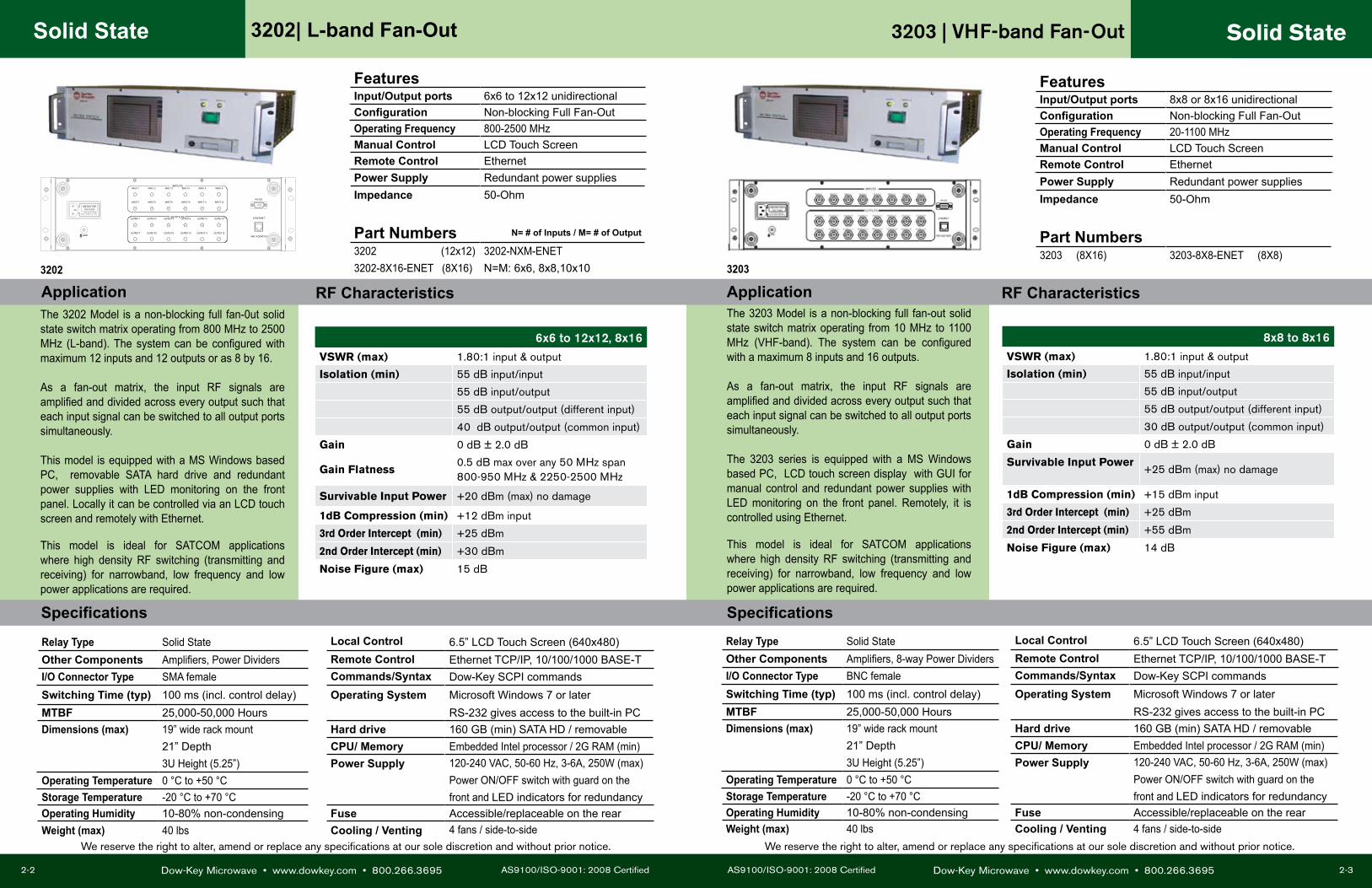
Application RF CharacteristicsThe 3203 Model is a non-blocking full fan-out solid state switch matrix operating from 10 MHz to 1100 MHz (VHF-band). The system can be configured with a maximum 8 inputs and 16 outputs.
As a fan-out matrix, the input RF signals are amplified and divided across every output such that each input signal can be switched to all output ports simultaneously. The 3203 series is equipped with a MS Windows based PC, LCD touch screen display with GUI for manual control and redundant power supplies with LED monitoring on the front panel. Remotely, it is controlled using Ethernet.
This model is ideal for SATCOM applications where high density RF switching (transmitting and receiving) for narrowband, low frequency and low power applications are required.
Solid State
Dow-Key Microwave • www.dowkey.com • 800.266.3695 AS9100/ISO-9001: 2008 Certified
3202| L-band Fan-Out
2-2
Solid State
The 3202 Model is a non-blocking full fan-0ut solid state switch matrix operating from 800 MHz to 2500 MHz (L-band). The system can be configured with maximum 12 inputs and 12 outputs or as 8 by 16.
As a fan-out matrix, the input RF signals are amplified and divided across every output such that each input signal can be switched to all output ports simultaneously. This model is equipped with a MS Windows based PC, removable SATA hard drive and redundant power supplies with LED monitoring on the front panel. Locally it can be controlled via an LCD touch screen and remotely with Ethernet.
This model is ideal for SATCOM applications where high density RF switching (transmitting and receiving) for narrowband, low frequency and low power applications are required.
Specifications
Application RF Characteristics
GND MAC ADDRESS:
ETHERNET
RS-232
D I SC O N N EC T PO WERBEFO R E R EPLAC I N G FU SES
OUTPUTSOUTPUT 1
OUTPUT 7
OUTPUT 2
OUTPUT 8
OUTPUT 3
OUTPUT 9
OUTPUT 4
OUTPUT 10
OUTPUT 5
OUTPUT 11
OUTPUT 6
OUTPUT 12
INPUT 1 INPUT 6INPUT 3INPUT 2 INPUT 4 INPUT 5
INPUT 12INPUT 9INPUT 7 INPUT 8 INPUT 10 INPUT 11
INPUTS
FeaturesInput/Output ports 6x6 to 12x12 unidirectionalConfiguration Non-blocking Full Fan-OutOperating Frequency 800-2500 MHzManual Control LCD Touch ScreenRemote Control EthernetPower Supply Redundant power suppliesImpedance 50-Ohm
Part Numbers N= # of Inputs / M= # of Output
3202 (12x12) 3202-NXM-ENET3202-8X16-ENET (8X16) N=M: 6x6, 8x8,10x10
6x6 to 12x12, 8x16VSWR (max) 1.80:1 input & output
Isolation (min) 55 dB input/input
55 dB input/output
55 dB output/output (different input)
40 dB output/output (common input)
Gain 0 dB ± 2.0 dB
Gain Flatness0.5 dB max over any 50 MHz span 800-950 MHz & 2250-2500 MHz
Survivable Input Power +20 dBm (max) no damage
1dB Compression (min) +12 dBm input
3rd Order Intercept (min) +25 dBm
2nd Order Intercept (min) +30 dBm
Noise Figure (max) 15 dB
Relay Type Solid State Local Control 6.5” LCD Touch Screen (640x480)Other Components Amplifiers, Power Dividers Remote Control Ethernet TCP/IP, 10/100/1000 BASE-TI/O Connector Type SMA female Commands/Syntax Dow-Key SCPI commands Switching Time (typ) 100 ms (incl. control delay) Operating System Microsoft Windows 7 or laterMTBF 25,000-50,000 Hours RS-232 gives access to the built-in PCDimensions (max) 19” wide rack mount Hard drive 160 GB (min) SATA HD / removable
21” Depth CPU/ Memory Embedded Intel processor / 2G RAM (min)3U Height (5.25”) Power Supply 120-240 VAC, 50-60 Hz, 3-6A, 250W (max)
Operating Temperature 0 °C to +50 °C Power ON/OFF switch with guard on theStorage Temperature -20 °C to +70 °C front and LED indicators for redundancyOperating Humidity 10-80% non-condensing Fuse Accessible/replaceable on the rearWeight (max) 40 lbs Cooling / Venting 4 fans / side-to-side
Relay Type Solid State Local Control 6.5” LCD Touch Screen (640x480)Other Components Amplifiers, 8-way Power Dividers Remote Control Ethernet TCP/IP, 10/100/1000 BASE-TI/O Connector Type BNC female Commands/Syntax Dow-Key SCPI commands Switching Time (typ) 100 ms (incl. control delay) Operating System Microsoft Windows 7 or laterMTBF 25,000-50,000 Hours RS-232 gives access to the built-in PCDimensions (max) 19” wide rack mount Hard drive 160 GB (min) SATA HD / removable
21” Depth CPU/ Memory Embedded Intel processor / 2G RAM (min)3U Height (5.25”) Power Supply 120-240 VAC, 50-60 Hz, 3-6A, 250W (max)
Operating Temperature 0 °C to +50 °C Power ON/OFF switch with guard on theStorage Temperature -20 °C to +70 °C front and LED indicators for redundancyOperating Humidity 10-80% non-condensing Fuse Accessible/replaceable on the rearWeight (max) 40 lbs Cooling / Venting 4 fans / side-to-side
8x8 to 8x16VSWR (max) 1.80:1 input & output
Isolation (min) 55 dB input/input
55 dB input/output
55 dB output/output (different input)
30 dB output/output (common input)
Gain 0 dB ± 2.0 dB
Survivable Input Power +25 dBm (max) no damage
1dB Compression (min) +15 dBm input
3rd Order Intercept (min) +25 dBm
2nd Order Intercept (min) +55 dBm
Noise Figure (max) 14 dB
FeaturesInput/Output ports 8x8 or 8x16 unidirectionalConfiguration Non-blocking Full Fan-OutOperating Frequency 20-1100 MHzManual Control LCD Touch ScreenRemote Control EthernetPower Supply Redundant power suppliesImpedance 50-Ohm
Part Numbers3203 (8X16) 3203-8X8-ENET (8X8)
Specifications
3202 3203
We reserve the right to alter, amend or replace any specifications at our sole discretion and without prior notice. We reserve the right to alter, amend or replace any specifications at our sole discretion and without prior notice.

AS9100/ISO-9001: 2008 Certified Dow-Key Microwave • www.dowkey.com • 800.266.3695
3205 | HF-band Fan-Out
2-5
Application RF CharacteristicsThe 3205 Model is a non-blocking full fan-out solid state switching system operating from 2 MHz to 32 MHz (HF-band). The system can be configured with a maximum 6 inputs and 12 outputs
As a fan-out matrix, the input RF signals are divided across every output such that each input signal can be switched to all output ports simultaneously. This model is equipped with a MS Windows based PC, removable SATA hard drive and redundant power supplies with LED monitoring on the front panel. Locally it can be controlled via an LCD touch screen and remotely with Ethernet.
This model is ideal for SATCOM applications where high density RF switching (transmitting and receiving) for narrowband, low frequency and low power applications are required.
Solid State
Dow-Key Microwave • www.dowkey.com • 800.266.3695 AS9100/ISO-9001: 2008 Certified
3204| IF-band Fan-Out
2-4
The 3204 Model is a non-blocking full fan-out solid state switching system operating from 20 MHz to 200 MHz (IF-band). The system can be configured to a maximum of 12 inputs and 12 outputs.
As a fan-out matrix, the input RF signals are divided across every output such that each input signal can be switched to all output ports simultaneously. This model is equipped with a MS Windows based PC, removable SATA hard drive and redundant power supplies with LED monitoring on the front panel. Locally it can be controlled via an LCD touch screen and remotely with Ethernet.
This model is ideal for SATCOM applications where high density RF switching (transmitting and receiving) for narrowband, low frequency and low power applications are required.
Specifications
Application RF Characteristics
GND MAC ADDRESS:
ETHERNET
RS-232
DISCONNECT POWERBEFORE REPLACING FUSES
OUTPUTSOUTPUT 1
OUTPUT 7
OUTPUT 2
OUTPUT 8
OUTPUT 3
OUTPUT 9
OUTPUT 4
OUTPUT 10
OUTPUT 5
OUTPUT 11
OUTPUT 6
OUTPUT 12
INPUTSINPUT 1 INPUT 6INPUT 3INPUT 2 INPUT 4 INPUT 5
INPUT 12INPUT 9INPUT 7 INPUT 8 INPUT 10 INPUT 11
Solid StateFeaturesInput/Output ports 6x6 to 12x12 unidirectionalConfiguration Non-blocking Full Fan-OutOperating Frequency 20-200 MHzManual Control LCD Touch ScreenRemote Control EthernetPower Supply Redundant power suppliesImpedance 50-Ohm
Part Numbers N= # of Inputs / M= # of Output
3204 (12x12) 3204-NXM-ENETN=M: 6x6, 8x8, 10x10
6x6 to 12x12
VSWR (max) 1.50:1 input & output
Isolation (min) 55 dB input/input
55 dB input/output
55 dB output/output (different input)
40 dB output/output (common input)
Gain 0 dB ± 1.0 dB
Gain Flatness 0.5 dB max over any 70 MHz span
Survivable Input Power +15 dBm (max) no damage
1dB Compression (min) +10 dBm input
3rd Order Intercept (min) +20 dBm
2nd Order Intercept (min) +35 dBm
Noise Figure (max) 15 dB
Relay Type Solid State Local Control 6.5” LCD Touch Screen (640x480)Other Components Amplifiers, Power Dividers Remote Control Ethernet TCP/IP, 10/100/1000 BASE-TI/O Connector Type SMA female Commands/Syntax Dow-Key SCPI commands Switching Time (typ) 100 ms (incl. control delay) Operating System Microsoft Windows 7 or laterMTBF 25,000-50,000 Hours RS-232 gives access to the built-in PCDimensions (max) 19” wide rack mount Hard drive 160 GB (min) SATA HD / removable
21” Depth CPU/ Memory Embedded Intel processor / 2G RAM (min)3U Height (5.25”) Power Supply 120-240 VAC, 50-60 Hz, 3-6A, 250W (max)
Operating Temperature 0 °C to +50 °C Power ON/OFF switch with guard on theStorage Temperature -20 °C to +70 °C front and LED indicators for redundancyOperating Humidity 10-80% non-condensing Fuse Accessible/replaceable on the rearWeight (max) 40 lbs Cooling / Venting 4 fans / side-to-side
FeaturesInput/Output ports 6x6 to 12x12 unidirectionalConfiguration Non-blocking Full Fan-OutOperating Frequency 2-32 MHzManual Control LCD Touch ScreenRemote Control EthernetPower Supply Redundant power suppliesImpedance 50-Ohm
Part Numbers3205 (6X12) 3205-6X6-ENET (6X6)
6x6 to 6x12VSWR (max) 1.80:1 input & output
Isolation (min) 50 dB input/input
50 dB input/output
50 dB output/output (different input)
30 dB output/output (common input)
Gain 0 dB ± 2.0 dB
Survivable Input Power +25 dBm (max) no damage
1dB Compression (min) +15 dBm input
3rd Order Intercept (min) +30 dBm
2nd Order Intercept (min) +60 dBm
Noise Figure (max) 10 dB
Relay Type Electromechanical Relay Local Control 6.5” LCD Touch Screen (640x480)Other Components Amplifiers, Power Dividers Remote Control Ethernet TCP/IP, 10/100/1000 BASE-TI/O Connector Type SMA female Commands/Syntax Dow-Key SCPI commands Switching Time (typ) 100 ms (incl. control delay) Operating System Microsoft Windows 7 or laterMTBF 25,000-50,000 Hours RS-232 gives access to the built-in PCDimensions (max) 19” wide rack mount Hard drive 160 GB (min) SATA HD / removable
21” Depth CPU/ Memory Embedded Intel processor / 2G RAM (min)3U Height (5.25”) Power Supply 120-240 VAC, 50-60 Hz, 3-6A, 250 W (max)
Operating Temperature 0 °C to +50 °C Power ON/OFF switch with guard on theStorage Temperature -20 °C to +70 °C front and LED indicators for redundancyOperating Humidity 10-80% non-condensing Fuse Accessible/replaceable on the rearWeight (max) 40 lbs Cooling / Venting 4 fans / side-to-side
Specifications
3204
3205
We reserve the right to alter, amend or replace any specifications at our sole discretion and without prior notice. We reserve the right to alter, amend or replace any specifications at our sole discretion and without prior notice.

FIBER OPTIC MATRICES

AS9100/ISO-9001: 2008 Certified Dow-Key Microwave • www.dowkey.com • 800.266.3695
7002 | C-band Crossbar/Fan-Out
3-3
Application RF Characteristics The 7002 models is a non-blocking 16x16 matrix with MEMS optical switches and splitters and it is configured as a 14x15 crossbar with a 1x2 fan-out switch segment. It switches input-to-output paths in pure optical domain with a operating wavelength of 1530-1565 nm in C-band.
The crossbar segment routes any input signal to any output port such that the path between the I/O ports is unique at any given time. Whereas the fan-out segment amplifies output 16 and re-routes it to input 15 & 16 to configure a 1x2 fan-out switch. See appendix C for more details.
This model is equipped with a MS Windows based PC, removable SATA hard drive and redundant power supplies with LED monitoring and guarded power switch on the front panel. Locally it can be controlled through an LCD touch screen with Graphical User Interface (GUI) and remotely through Ethernet.
Fiber Optic
Dow-Key Microwave • www.dowkey.com • 800.266.3695 AS9100/ISO-9001: 2008 Certified
7001 | C-band Crossbar/Fan-Out
3-2
The 7001 models is a non-blocking 16x16 matrix with MEMS optical switches and splitters and it is configured as a 8x14 crossbar with two 1x4 fan-out switch segments. It switches input-to-output paths in pure optical domain with a operating wavelength of 1530-1565 nm in C-band.
The crossbar segment routes any input signal to any output port such that the path between the I/O ports is unique at any given time. Whereas the fan-out configuration re-routes outputs 15 &16 back to inputs 9-to-12 & 13-to-16 respectively to make two 1x4 fan-out segments. See appendix C for more details.
This model is equipped with a MS Windows based PC, removable SATA hard drive and redundant power supplies with LED monitoring and guarded power switch on the front panel. Locally it can be controlled through an LCD touch screen with Graphical User Interface (GUI) and remotely through Ethernet.
Specifications
Application RF Characteristics
Fiber Optic
FeaturesInput/Output Configurations 16x16 Matrix
utilized as 8x14 Crossbarwith two 1x4 Fan-Out Segments
Operating Frequency 1530-1565 nm (C-band)Manual Control LCD Touch ScreenRemote Control Ethernet
Part Number7001
Crossbar Segment
Fan-Out Segment
Insertion Loss (1) (max) 2 dB 1.60 dB
Crosstalk (max) -70 dB -70 dB
Back Reflection (max) -50 dB -50 dB
TDL (2) (max) 0.30 dB 0.30 dB
WDL(3) (max) 0.25 dB 0.25 dB
PDL (4) (max) 0.05 dB 0.05 dB
Repeatability (max) ± 0.02 dB ± 0.02 dB
Stability (max) ± 0.02 dB ± 0.02 dB
Optical Power (max) 500 mW 500 mW
Relay Type Non-Latching MEMS Local Control 6.5” (640x480) LCD Touch Screen GUII/O Connector Type LC USB port for keyboard or mouseSwitching Time (max) 35 ms (excl. software delay) Remote Control Ethernet (TCP/IP)Fiber Type 9/125 mm single mode Fault & Error Reporting via Ethernet and LCD (visual)Lifetime (min) 109 cycles Commands/Syntax Dow-Key SCPI commands Dimensions (max) 19” wide full rack Operating System Microsoft Windows
20” Depth Hard drive (min) 120 GB SATA HD / removable3U Height (5.25”) Power Supply 120-240 VAC, 50-60 Hz, 250 W (max)
Operating Temperature 0 °C to +50 °C Power ON/OFF switch with guard on theStorage Temperature -20 °C to +65 °C front and LED indicators for redundancyOperating Humidity 10-80% non-condensing Fuse Accessible/replaceable on the rearWeight (typ) 30 lbs Cooling / Venting 2 fans / side-to-side
Specifications
FeaturesInput/Output Configurations 16x16 Matrix
utilized as 14x15 crossbarwith a 1x2 Fan-Out Segment
Operating Frequency 1530-1560 nm (C-band)Manual Control LCD Touch ScreenRemote Control Ethernet
Part Number7002
Crossbar Segment
Fan-Out Segment
Insertion Loss (1) (max) 2 dB 5.4 dB
Crosstalk (max) -70 dB -70 dB
Back Reflection (max) -47 dB -47 dB
TDL (2) (max) 0.40 dB 0.55 dB
PDL (3) (max) 0.20 dB 0.30 dB
Repeatability (max) ± 0.04 dB ± 0.04 dB
Optical Power (max) 500 mW 500 mW
Relay Type Non-Latching MEMS Local Control 6.5” (640x480) LCD Touch Screen GUII/O Connector Type FC/APC USB port for keyboard or mouseSwitching Time (max) 35 ms (excl. software delay) Remote Control Ethernet (TCP/IP)Filter Type 9 mm single mode Fault & Error Reporting via Ethernet and LCD (visual)Lifetime (min) 109 cycles Commands/Syntax Dow-Key SCPI commands Dimensions (max) 19” wide full rack Operating System Microsoft Windows
20” Depth Hard drive (min) 120 GB SATA HD / removable3U Height (5.25”) Power Supply 120-240 VAC, 50-60 Hz, 250 W (max)
Operating Temperature 0 °C to +50 °C Power ON/OFF switch with guard on theStorage Temperature -20 °C to +65 °C front and LED indicators for redundancyOperating Humidity 10-80% non-condensing Fuse Accessible/replaceable on the rearWeight (typ) 30 lbs Cooling / Venting 2 fans / side-to-side
70027001
SEE APPENDIX C FOR SWITCH SCHEMATIC SEE APPENDIX C FOR SWITCH SCHEMATIC
(1) Measured at 1550 nm(2) Time Dependent Loss(3) Wavelength Dependent Loss specified in ± 20nm range(4) Polarization Dependent Loss
(1) Measured at 1550 nm(2) Time Dependent Loss(3) Polarization Dependent Loss
INTEGRATED SWITCH SYSTEM
CAPABILITIES
AS9100/ISO-9001: 2008 Certified Dow-Key Microwave • www.dowkey.com • 800.266.3695
5190/5191 | L-band Fan-In/Fan-Out
4-3
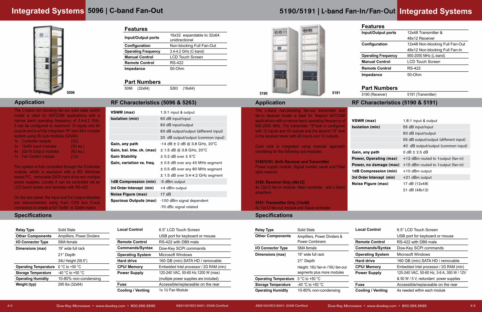
The L-band non-blocking fan-out transmitter and fan-in receiver model is ideal for Teleport SATCOM applications with a narrow band operating frequency of 950-2050 MHz. The transmitter 19”rack is configured with 12 inputs and 48 outputs and the second 19” rack is the receiver tower with 48 inputs and 12 outputs.
Each rack is integrated using modular approach consisting for the following sub-modules:
5190/5191: Both Receiver and Transmitter Power supply module, Signal monitor panel and Fiber optic receiver
5190: Receiver Only (48x12)4x 12x12 fan-in module, Main controller and L-Band amplifiers
5191: Transmitter Only (12x48)4x 12x12 fan-out module and Slave controller
Integrated Systems
FeaturesInput/Output ports 12x48 Transmitter &
48x12 ReceiverConfiguration 12x48 Non-blocking Full Fan-Out
48x12 Non-blocking Full Fan-InOperating Frequency 950-2050 MHz (L-band)Manual Control LCD Touch Screen
Remote Control RS-422Impedance 50-Ohm
Part Numbers5190 (Receiver) 5191 (Transmitter)
VSWR (max) 1.8:1 input & output
Isolation (min) 55 dB input/input
60 dB input/output
55 dB output/output (different input)
40 dB output/output (common input)
Gain, any path 0 dB ± 2.5 dB
Power, Operating (max) +12 dBm routed to 1output (fan-in)
Power, no damage (max) +15 dBm routed to 1output (fan-in)
1dB Compression (min) +10 dBm output
3rd Order Intercept (min) +21 dBm output
Noise Figure (max) 17 dB (12x48)
21 dB (48x12)
Relay Type Solid State Local Control 6.5” LCD Touch Screen Other Components Amplifiers, Power Dividers &
Power CombinersUSB port for keyboard or mouse
Remote Control RS-422 with DB9 male I/O Connector Type SMA female Commands/Syntax Dow-Key SCPI commands Dimensions (max) 19” wide full rack Operating System Microsoft Windows
21” Depth Hard drive 160 GB (min) SATA HD / removableHeight: 16U fan-in /16U fan-out segments plus more modules
CPU/ Memory Embedded Intel processor / 2G RAM (min)Power Supply 120-240 VAC, 50-60 Hz, 3-6 A, 350 W / 12V
Operating Temperature 0 °C to +50 °C & 50 W / 5 V, redundant power suppliesStorage Temperature -40 °C to +50 °C Fuse Accessible/replaceable on the rearOperating Humidity 10-80% non-condensing Cooling / Venting As needed within each module
51915190
Dow-Key Microwave • www.dowkey.com • 800.266.3695 AS9100/ISO-9001: 2008 Certified
5096 | C-band Fan-Out
4-2
The C-band non-blocking fan-out solid state switch model is ideal for SATCOM applications with a narrow band operating frequency of 3.4-4.2 GHz. It can be configured to maximum 16 inputs and 64 outputs and is a fully integrated 19” rack 34U modular system using (8) sub-modules (32x64):1x Controller module (3U)2x 16x64 Input modules (3U ea.)4x 32x16 Output modules (6U ea.)1x Fan Control module (1U)
The system is fully controlled through the Controller module, which is equipped with a MS Windows based PC, removable SATA hard drive and multiple power supplies. Locally it can be controlled via an LCD touch screen and remotely with RS-422.
On the rear panel, the Input and the Output Modules are interconnected using 9-pin CAN bus D-sub connectors to create a full 16x64 or 32x64 matrix.
Specifications
Application RF Characteristics (5096 & 5263)
Integrated Systems
FeaturesInput/Output ports 16x32 expandable to 32x64
unidirectionalConfiguration Non-blocking Full Fan-OutOperating Frequency 3.4-4.2 GHz (C-band)Manual Control LCD Touch ScreenRemote Control RS-422Impedance 50-Ohm
Part Numbers5096 (32x64) 5263 (16x64)
VSWR (max) 1.3:1 input & output
Isolation (min) 60 dB input/input
60 dB input/output
60 dB output/output (different input)
20 dB output/output (common input)
Gain, any path -14 dB ± 2 dB @ 3.8 GHz, 20°CGain, bal. btw. ch. (max) ± 1.5 dB @ 3.8 GHz, 20°CGain Stability ± 0.2 dB over ± 5°CGain, variation vs. freq. ± 0.5 dB over any 40 MHz segment
± 0.5 dB over any 80 MHz segment
± 1.5 dB over 3.4-4.2 GHz segment
1dB Compression (min) -5 dBm output
3rd Order Intercept (min) +4 dBm output
Noise Figure (max) 17 dB
Spurious Outputs (max) -100 dBm signal dependent
-70 dBc signal related
Relay Type Solid State Local Control 6.5” LCD Touch Screen Other Components Amplifiers, Power Dividers USB port for keyboard or mouseI/O Connector Type SMA female Remote Control RS-422 with DB9 male Dimensions (max) 19” wide full rack Commands/Syntax Dow-Key SCPI commands
21” Depth Operating System Microsoft Windows34U Height (59.5”) Hard drive 160 GB (min) SATA HD / removable
Operating Temperature 0 °C to +50 °C CPU/ Memory Embedded Intel processor / 2G RAM (min)Storage Temperature -40 °C to +50 °C Power Supply 120-240 VAC, 50-60 Hz,1200 W (max) Operating Humidity 10-80% non-condensing (multiple power supplies are included)Weight (typ) 295 lbs (32x64) Fuse Accessible/replaceable on the rear
Cooling / Venting 1x 1U Fan Module
5096
RF Characteristics (5190 & 5191)Application
Specifications

AS9100/ISO-9001: 2000 Certified Dow-Key Microwave • www.dowkey.com • 800.266.3695 ii
APPENDIXRF DATA & SCHEMATICS
Dow-Key Microwave • www.dowkey.com • 800.266.3695 AS9100/ISO-9001: 2008 Certified
5230 | L-band Fan-In/Fan-Out
4-4
The L-band non-blocking fan-out/fan-in solid state switch model is a compact 4x48 and 48x4 switch matrix solution integrated with a modular approach using (7) sub-modules:3x 16x4 Fan-in modules (1U ea.)1x Controller module (3U)3x 4x16 Fan-out modules (1U ea.)
The system is fully controlled through the Controller module, which is equipped with a MS Windows based PC and two removable and replaceable power supplies cartridges. Locally it can be controlled from an LCD touch screen and remotely via Ethernet with SNMP v1 protocol.
On the rear panel, the fan-in and the fan-out modules are interconnected using RJ11 CAN bus connectors to create a full 4x48 and 48x4 matrix. (The 8x2 switch resides inside the control module)
Specifications
Application RF Characteristics (4x48 & 48x4)
Integrated Systems
VSWR (max) 1.8:1 input & output
Isolation (min) 60 dB input/input
60 dB input/output
60 dB output/output (different input)
fan-in only 60 dB output/output (common input)
fan-out only 40 dB output/output (common input)
Gain +2 dB ± 2 dB
Power, Operating (max) +3 dBm routed to 1 output (fan-in)
+14 dBm routed to 1 output (fan-out)
1dB Compression (min) 1 dBm (fan-in)
8 dBm (fan-out)
3rd Order Intercept (min) +17 dBm (fan-in), -9 dBm input power
+24 dBm (fan-out), +6 dBm input power
Noise Figure (max) 20 dB (fan-in)
18 dB (fan-out)
Relay Type Solid State Local Control 6.5” LCD Touch Screen GUIOther Components Amplifiers, Power Dividers &
Power CombinersUSB port for keyboard or mouse
Remote Control Ethernet with SNMP v1 protocolI/O Connector Type SMA female 2x RJ-45 connectors availableDimensions (max) 19” Wide Operating System Microsoft Windows
21” Depth Hard drive 160 GB (min) SATA HD / removable9U Height (15.75”) CPU/ Memory Embedded Intel processor / 2G RAM (min)
Operating Temperature 0 °C to +40 °C Power Supply 120-240 VAC, 50-60 Hz, 2x 300 W (max) Storage Temperature -40 °C to +40 °C 2x power module cartridges, Power ON/OFFOperating Humidity 10-80% non-condensing switch with guard on the front panel
Fuse Accessible/replaceable on the rear
FeaturesInput/Output Configuration 4x48 Non-Blocking Full Fan-Out
48x4 Non-Blocking Full Fan-In8x2 Electromechanical Matrix(1)
Operating Frequency 950-2050 MHz (L-band)
Manual Control LCD Touch ScreenRemote Control 2x Ethernet ports, SNMPImpedance 50-Ohm
Part Number52305230
(1) not discussed on this data sheet
AS9100/ISO-9001: 2008 Certified Dow-Key Microwave • www.dowkey.com • 800.266.3695
MP-Series RF Data
5-3
Appendix B
Dow-Key Microwave • www.dowkey.com • 800.266.3695 AS9100/ISO-9001: 2008 Certified
Determine Enclosure Height
5-2
Appendix A
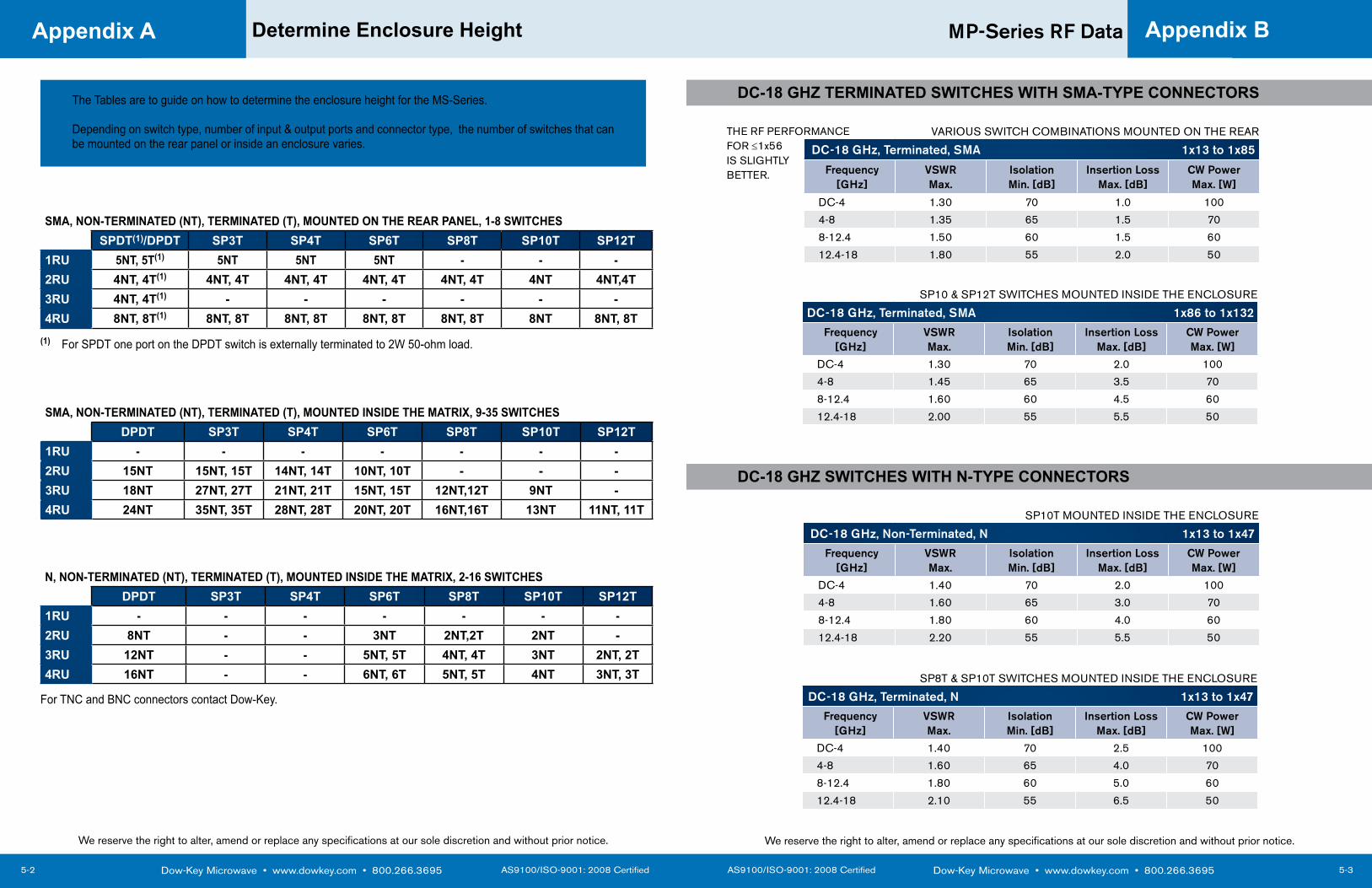
SMA, NON-TERMINATED (NT), TERMINATED (T), MOUNTED ON THE REAR PANEL, 1-8 SWITCHESSPDT(1)/DPDT SP3T SP4T SP6T SP8T SP10T SP12T
1RU 5NT, 5T(1) 5NT 5NT 5NT - - -2RU 4NT, 4T(1) 4NT, 4T 4NT, 4T 4NT, 4T 4NT, 4T 4NT 4NT,4T3RU 4NT, 4T(1) - - - - - -4RU 8NT, 8T(1) 8NT, 8T 8NT, 8T 8NT, 8T 8NT, 8T 8NT 8NT, 8T
SMA, NON-TERMINATED (NT), TERMINATED (T), MOUNTED INSIDE THE MATRIX, 9-35 SWITCHESDPDT SP3T SP4T SP6T SP8T SP10T SP12T
1RU - - - - - - -2RU 15NT 15NT, 15T 14NT, 14T 10NT, 10T - - -3RU 18NT 27NT, 27T 21NT, 21T 15NT, 15T 12NT,12T 9NT -4RU 24NT 35NT, 35T 28NT, 28T 20NT, 20T 16NT,16T 13NT 11NT, 11T
(1) For SPDT one port on the DPDT switch is externally terminated to 2W 50-ohm load.
N, NON-TERMINATED (NT), TERMINATED (T), MOUNTED INSIDE THE MATRIX, 2-16 SWITCHESDPDT SP3T SP4T SP6T SP8T SP10T SP12T
1RU - - - - - - -2RU 8NT - - 3NT 2NT,2T 2NT -3RU 12NT - - 5NT, 5T 4NT, 4T 3NT 2NT, 2T4RU 16NT - - 6NT, 6T 5NT, 5T 4NT 3NT, 3T
For TNC and BNC connectors contact Dow-Key.
The Tables are to guide on how to determine the enclosure height for the MS-Series.
Depending on switch type, number of input & output ports and connector type, the number of switches that can be mounted on the rear panel or inside an enclosure varies. DC-18 GHz, Terminated, SMA 1x13 to 1x85
Frequency [GHz]
VSWRMax.
Isolation Min. [dB]
Insertion Loss Max. [dB]
CW PowerMax. [W]
DC-4 1.30 70 1.0 100
4-8 1.35 65 1.5 70
8-12.4 1.50 60 1.5 60
12.4-18 1.80 55 2.0 50
VARIOUS SWITCH COMBINATIONS MOUNTED ON THE REAR
We reserve the right to alter, amend or replace any specifications at our sole discretion and without prior notice.
DC-18 GHz, Terminated, SMA 1x86 to 1x132
Frequency [GHz]
VSWRMax.
Isolation Min. [dB]
Insertion Loss Max. [dB]
CW PowerMax. [W]
DC-4 1.30 70 2.0 100
4-8 1.45 65 3.5 70
8-12.4 1.60 60 4.5 60
12.4-18 2.00 55 5.5 50
SP10 & SP12T SWITCHES MOUNTED INSIDE THE ENCLOSURE
DC-18 GHz, Non-Terminated, N 1x13 to 1x47
Frequency [GHz]
VSWRMax.
Isolation Min. [dB]
Insertion Loss Max. [dB]
CW PowerMax. [W]
DC-4 1.40 70 2.0 100
4-8 1.60 65 3.0 70
8-12.4 1.80 60 4.0 60
12.4-18 2.20 55 5.5 50
SP10T MOUNTED INSIDE THE ENCLOSURE
DC-18 GHz, Terminated, N 1x13 to 1x47
Frequency [GHz]
VSWRMax.
Isolation Min. [dB]
Insertion Loss Max. [dB]
CW PowerMax. [W]
DC-4 1.40 70 2.5 100
4-8 1.60 65 4.0 70
8-12.4 1.80 60 5.0 60
12.4-18 2.10 55 6.5 50
SP8T & SP10T SWITCHES MOUNTED INSIDE THE ENCLOSURE
DC-18 GHZ TERMINATED SWITCHES WITH SMA-TYPE CONNECTORS
DC-18 GHZ SWITCHES WITH N-TYPE CONNECTORS
We reserve the right to alter, amend or replace any specifications at our sole discretion and without prior notice.
THE RF PERFORMANCEFOR ≤1x56 IS SLIGHTLYBETTER.

AS9100/ISO-9001: 2008 Certified Dow-Key Microwave • www.dowkey.com • 800.266.3695
Switch Schematics
5-5
Appendix C
Dow-Key Microwave • www.dowkey.com • 800.266.3695 AS9100/ISO-9001: 2008 Certified
Switch Schematics
5-4
Appendix C
MS-SERIES: Exmaple of Individual Switches
We reserve the right to alter, amend or replace any specifications at our sole discretion and without prior notice.
CB-SERIES: Example of Crossbar Switch Configurations
MP-SERIES: Example of 1xN Switch Configurations
We reserve the right to alter, amend or replace any specifications at our sole discretion and without prior notice.
4x SP4T NON-TERMINATED SWITCH 4x SP8T TERMINATED SWITCH
1x16 NON-TERMINATED SWITCH 1x100 NON-TERMINATED SWITCH
1x20 NON-TERMINATED SWITCHMOUNTED ON THE REAR(OUTSIDE THE ENCLOSURE)
6X8 NON-TERMINATED SWITCH
4X4 NON-TERMINATED SWITCH
1x DPDT SWITCH

Dow-Key Microwave • www.dowkey.com • 800.266.3695 AS9100/ISO-9001: 2008 Certified
Switch Schematics
5-6
Appendix C
MP-SERIES: SWITCHES CASCADED 2-LEVELSMODEL 4141: 2X32 Switch Configuration
7001 Switch Configuration 7002 Switch Configuration
We reserve the right to alter, amend or replace any specifications at our sole discretion and without prior notice.
Dow-Key Microwave4822 McGrath Street, Ventura, CA 93003 USATel +1.805.650.0260Fax +1.805.650.1734Email [email protected]
BSC Filters Ltd.Jorvik House , Outgang Lane, York, YO19 5UP, EnglandTel +44.1904.438438 Fax +44.1904.438123Email [email protected]
K&L Microwave2250 Northwood Drive, Salisbury, MD 21801 USATel +1.410.749.2424Fax +1.443.260.2268Email [email protected]
Pole/Zero Corporation5558 Union Centre Drive, West Chester, OH 45069 USATel +1.513.870.9060Fax +1.513.870.9064Email [email protected]
Microwave Products Group (MPG) designs, manufactures and sells special electronic components and systems, including high-performance filters, switches, diplexers, duplexers, Integrated Cosite Equipments (ICE), EMI filters and Low PIM solutions. Our products are used in military, space, telecom infrastructure, medical and industrial applications where function and reliability are crucial.
MICROWAVE PRODUCTS GROUP
4822 McGrath Street | Ventura, CA 93003-5641Tel 805.650.0260 | Fax 805.650.1734 | www.dowkey.com