pim sparse mode for ipv6 (pim-smv6) - allied telesis · pim-smv6 embedded rp, rp and bsr candidate...
TRANSCRIPT
FEATURE OVERVIEW AND CONFIGURATION GUIDE
PIM Sparse Mode for IPv6 (PIM-SMv6)
IntroductionThis guide provides information about Protocol Independent Multicast-Sparse Mode for IPv6 (PIM-SMv6).
Products and software version that apply to this guide
This guide applies to AlliedWare Plus™ products that support PIM-SMv6, running version 5.4.4 or later.
To see whether your product supports PIM-SMv6, see the following documents:
The product’s Datasheet
The AlliedWare Plus Datasheet
The product’s Command Reference
These documents are available from the above links on our website at alliedtelesis.com.
Feature support may change in later software versions. For the latest information, see the above documents.
alliedtelesis.com xC613-22036-00 REV A
Related Documents
Related DocumentsThe following documents give more information about the IPv6 multicasting features on AlliedWare Plus products:
the Multicasting Feature Overview and Configuration Guide
the MLD Feature Overview and Configuration Guide
the Command Reference for each product
These documents are available from the links above or on our website at alliedtelesis.com.
ContentIntroduction............................................................................................................................................................................. 1
Products and software version that apply to this guide ....................................................................... 1
Related Documents............................................................................................................................................................ 2
PIM-SMv6 ................................................................................................................................................................................. 3
Characteristics of PIM-SMv6.......................................................................................................................................... 4
PIM-SMv6 Embedded RP, RP and BSR Candidate Configurations .......................................................... 4
Embedded RP configuration................................................................................................................................. 4
Verify embedded RP configuration................................................................................................................... 6
RP and BSR candidate configuration ............................................................................................................... 7
Verify RP and RP candidate configuration ................................................................................................. 10
PIM-SMv6 Static RP, DR, BSR Configurations ................................................................................................... 12
Static Rendezvous Point configuration......................................................................................................... 13
Verify static Rendezvous Point configuration ........................................................................................... 14
Dynamic Rendezvous Point configuration................................................................................................. 16
Verify PIM group-to-RP mappings.................................................................................................................. 17
Verify RP details ........................................................................................................................................................ 17
Boot Strap Router configuration .................................................................................................................... 18
Verify Boot Strap Router configuration ...................................................................................................... 19
Page 2 | PIM Sparse Mode for IPv6 (PIM-SMv6)
PIM-SMv6
PIM-SMv6Protocol Independent Multicast-Sparse Mode for IPv6 (PIM-SMv6) provides efficient communication between members of sparsely distributed groups—the type of groups that are most common in wide-area internetworks.
PIM-SMv6 helps geographically dispersed network nodes to conserve bandwidth and reduce traffic by simultaneously delivering a single stream of information to multiple locations. PIM-SMv6 uses the IPv6 multicast model of receiver-initiated membership, supporting both shared and shortest-path trees and uses mechanisms to adapt to changing network conditions. PIM-SMv6 uses a topology gathering approach to populate a multicast routing table with routes.
Note: IPv6 must be enabled on an interface with the ipv6 enable command, IPv6 forwarding must be enabled globally for routing IPv6 with the ipv6 forwarding command, and IPv6 multicasting must be enabled globally with the ipv6 multicast-routing command before using PIM-SMv6 commands. Static IPv6 multicast routes take priority over dynamic IPv6 multicast routes. Use the clear ipv6 mroute command to clear static IPv6 multicast routes and ensure dynamic IPv6 multicast routes can take over from previous static IPv6 multicast routes.
Note: The IPv6 Multicast addresses shown can be derived from IPv6 unicast prefixes as per RFC 3306.The IPv6 unicast prefix reserved for documentation is 2001:0db8::/32 as per RFC 3849. Using the base /32 prefix the IPv6 multicast prefix for 2001:0db8::/32 is ff3x:20:2001:0db8::/64. Where an RP address is 2001:0db8::1 the embedded RP multicast prefix is ff7x:120:2001:0db8::/96. For ASM (Any-Source Multicast) the IPV6 multicast addresses allocated for documentation purposes are ff0x::0db8:0:0/96 as per RFC 6676. This is a /96 prefix so that it can be used with group IDs as per RFC 3307. These addresses should not be used for practical networks (other than for testing purposes), nor should they appear in any public network.
Note: The IPv6 addresses shown use the address space 2001:0db8::/32, defined in RFC 3849 for documentation purposes. These addresses should not be used for practical networks (other than for testing purposes) nor should they appear on any public network.
PIM Sparse Mode for IPv6 (PIM-SMv6) | Page 3
Characteristics of PIM-SMv6
Characteristics of PIM-SMv6PIM Sparse Mode for IPv6 (PIM-SMv6) is defined by standards that are almost identical to those that define PIM for IPv4. For a description of the protocol, refer to the PIM-SM Feature Overview and Configuration Guide.
PIM-SMv6 Embedded RP, RP and BSR Candidate ConfigurationsThis section provides two PIM-SMv6 configuration examples:
Embedded RP configuration
RP and BSR candidate configuration
Embedded RP configuration
RFC 3956 describes a multicast address allocation policy, in which the address of the Rendezvous Point (RP) is encoded in the IPv6 multicast group address, and specifies a PIM-SMv6 group-to-RP mapping to use the encoding, leveraging and extending unicast-prefix-based addressing.
Embedded RP multicast group address format
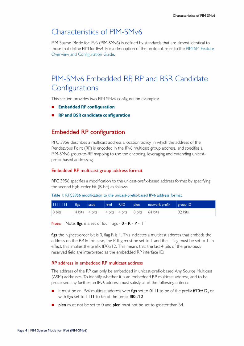
RFC 3956 specifies a modification to the unicast-prefix-based address format by specifying the second high-order bit (R-bit) as follows:
Note: Note: flgs is a set of four flags - 0 - R - P - T
flgs the highest-order bit is 0, flag R is 1. This indicates a multicast address that embeds the address on the RP. In this case, the P flag must be set to 1 and the T flag must be set to 1. In effect, this implies the prefix ff70::/12. This means that the last 4 bits of the previously reserved field are interpreted as the embedded RP interface ID.
RP address in embedded RP multicast address
The address of the RP can only be embedded in unicast-prefix-based Any Source Multicast (ASM) addresses. To identify whether it is an embedded RP multicast address, and to be processed any further, an IPv6 address must satisfy all of the following criteria:
It must be an IPv6 multicast address with flgs set to 0111 to be of the prefix ff70::/12, or with flgs set to 1111 to be of the prefix fff0::/12
plen must not be set to 0 and plen must not be set to greater than 64.
Table 1: RFC3956 modification to the unicast-prefix-based IPv6 address format
11111111 flgs scop rsvd RIID plen network prefix group ID
8 bits 4 bits 4 bits 4 bits 4 bits 8 bits 64 bits 32 bits
Page 4 | PIM Sparse Mode for IPv6 (PIM-SMv6)
PIM-SMv6 Embedded RP, RP and BSR Candidate Configurations
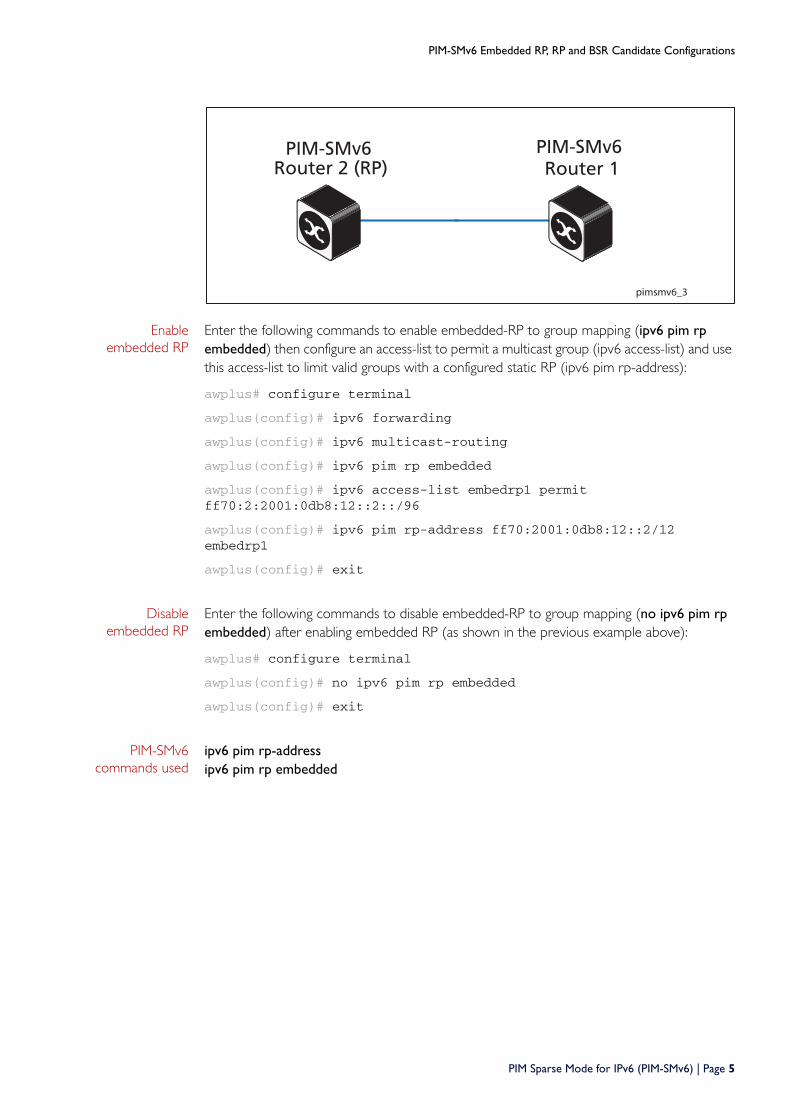
Enable embedded RP
Enter the following commands to enable embedded-RP to group mapping (ipv6 pim rp embedded) then configure an access-list to permit a multicast group (ipv6 access-list) and use this access-list to limit valid groups with a configured static RP (ipv6 pim rp-address):
awplus# configure terminal
awplus(config)# ipv6 forwarding
awplus(config)# ipv6 multicast-routing
awplus(config)# ipv6 pim rp embedded
awplus(config)# ipv6 access-list embedrp1 permit ff70:2:2001:0db8:12::2::/96
awplus(config)# ipv6 pim rp-address ff70:2001:0db8:12::2/12 embedrp1
awplus(config)# exit
Disable embedded RP
Enter the following commands to disable embedded-RP to group mapping (no ipv6 pim rp embedded) after enabling embedded RP (as shown in the previous example above):
awplus# configure terminal
awplus(config)# no ipv6 pim rp embedded
awplus(config)# exit
PIM-SMv6 commands used
ipv6 pim rp-addressipv6 pim rp embedded
pimsmv6_3
Router 2 (RP) Router 1PIM-SMv6 PIM-SMv6
PIM Sparse Mode for IPv6 (PIM-SMv6) | Page 5
PIM-SMv6 Embedded RP, RP and BSR Candidate Configurations
Verify embedded RP configuration
Use the following commands to verify the embedded-RP configuration. Note that the group-to-RP mapping for embedded-RP addresses is created when the group is first seen at a PIM-SMv6 router. This can be due to the MLD local receiver report, Join/Prune and Register message processing.
Verify RP-mapping in RP
Verify RP-mapping in non-RP
awplus#show ipv6 pim sparse-mode rp mappingPIM Group-to-RP MappingsGroup(s): ff7e:240:3ffe:172:31:12::/96, Static RP: 3ffe:172:31:12::2 Uptime: 00:04:12Embedded RP Groups:Group(s): ff7e:240:3ffe:172:31:12::/96 RP: 3ffe:172:31:12::2, Uptime: 00:00:33
mv66#show ipv6 pim sparse-mode rp mappingPIM Group-to-RP MappingsEmbedded RP Groups:Group(s): ff7e:240:3ffe:172:31:12::/96 RP: 3ffe:172:31:12::2, Uptime: 00:00:27
Page 6 | PIM Sparse Mode for IPv6 (PIM-SMv6)
PIM-SMv6 Embedded RP, RP and BSR Candidate Configurations
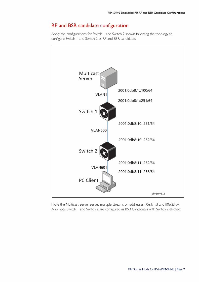
RP and BSR candidate configuration
Apply the configurations for Switch 1 and Switch 2 shown following the topology to configure Switch 1 and Switch 2 as RP and BSR candidates.
Note the Multicast Server serves multiple streams on addresses ff0e:1:1::3 and ff0e:3:1::4. Also note Switch 1 and Switch 2 are configured as BSR Candidates with Switch 2 elected.
pimsmv6_2
Switch 1
Switch 2
VLAN1
VLAN600
VLAN601
2001:0db8:1::100/64
2001:0db8:1::251/64
2001:0db8:10::251/64
2001:0db8:10::252/64
2001:0db8:11::253/64
PC Client
2001:0db8:11::252/64
MulticastServer
PIM Sparse Mode for IPv6 (PIM-SMv6) | Page 7
PIM-SMv6 Embedded RP, RP and BSR Candidate Configurations
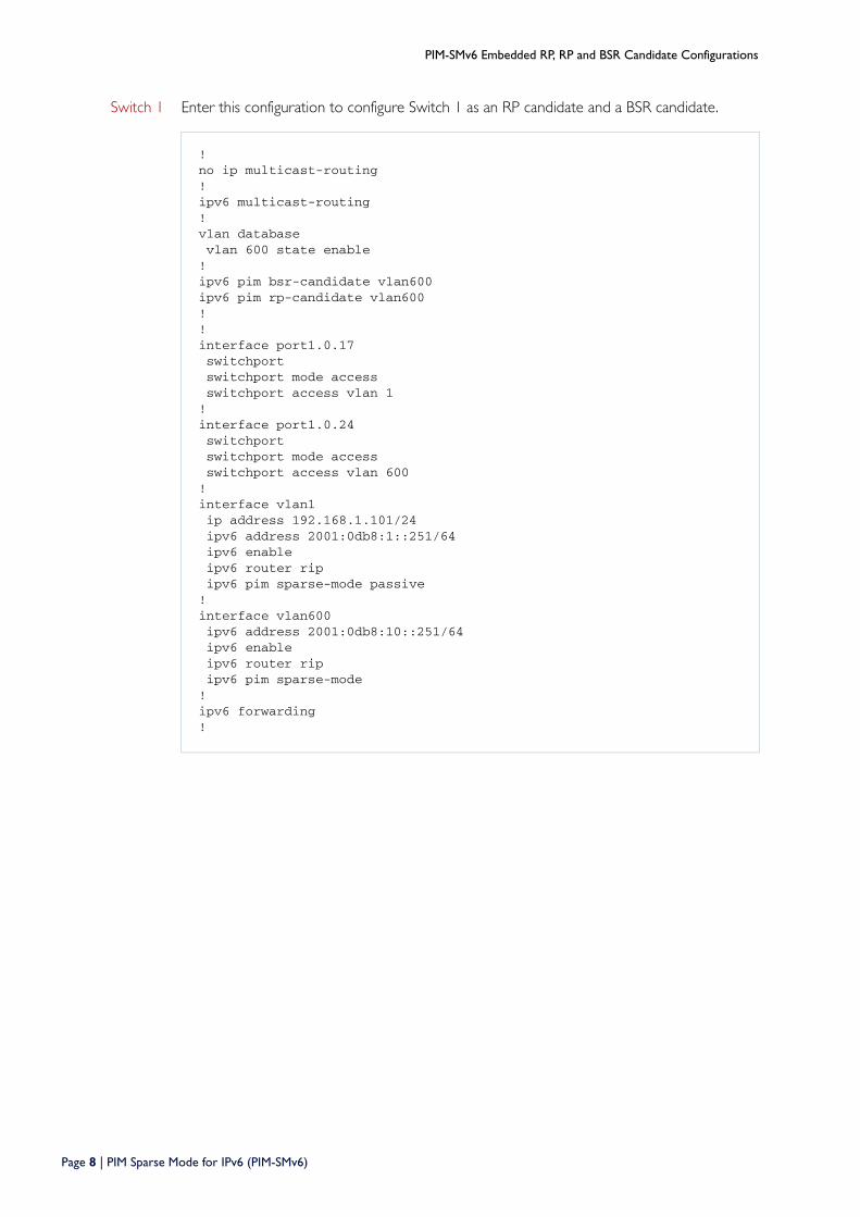
Switch 1 Enter this configuration to configure Switch 1 as an RP candidate and a BSR candidate.
! no ip multicast-routing ! ipv6 multicast-routing ! vlan database vlan 600 state enable ! ipv6 pim bsr-candidate vlan600 ipv6 pim rp-candidate vlan600 ! ! interface port1.0.17 switchport switchport mode access switchport access vlan 1 ! interface port1.0.24 switchport switchport mode access switchport access vlan 600 ! interface vlan1 ip address 192.168.1.101/24 ipv6 address 2001:0db8:1::251/64 ipv6 enable ipv6 router rip ipv6 pim sparse-mode passive ! interface vlan600 ipv6 address 2001:0db8:10::251/64 ipv6 enable ipv6 router rip ipv6 pim sparse-mode ! ipv6 forwarding !
Page 8 | PIM Sparse Mode for IPv6 (PIM-SMv6)
PIM-SMv6 Embedded RP, RP and BSR Candidate Configurations
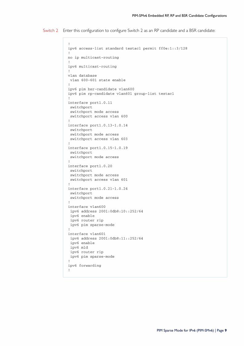
Switch 2 Enter this configuration to configure Switch 2 as an RP candidate and a BSR candidate:
! ipv6 access-list standard testacl permit ff0e:1::3/128 ! no ip multicast-routing ! ipv6 multicast-routing !vlan database vlan 600-601 state enable ! ipv6 pim bsr-candidate vlan600 ipv6 pim rp-candidate vlan601 group-list testacl ! interface port1.0.11 switchport switchport mode access switchport access vlan 600 ! interface port1.0.13-1.0.14 switchport switchport mode access switchport access vlan 603 ! interface port1.0.15-1.0.19 switchport switchport mode access ! interface port1.0.20 switchport switchport mode access switchport access vlan 601 ! interface port1.0.21-1.0.24 switchport switchport mode access ! interface vlan600 ipv6 address 2001:0db8:10::252/64 ipv6 enable ipv6 router rip ipv6 pim sparse-mode ! interface vlan601 ipv6 address 2001:0db8:11::252/64 ipv6 enable ipv6 mld ipv6 router rip ipv6 pim sparse-mode ! ipv6 forwarding !
PIM Sparse Mode for IPv6 (PIM-SMv6) | Page 9
PIM-SMv6 Embedded RP, RP and BSR Candidate Configurations
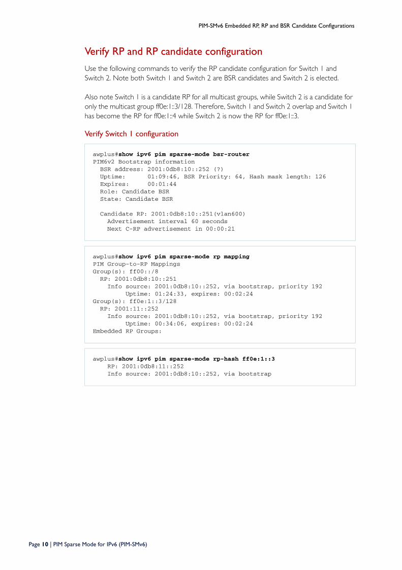
Verify RP and RP candidate configuration
Use the following commands to verify the RP candidate configuration for Switch 1 and Switch 2. Note both Switch 1 and Switch 2 are BSR candidates and Switch 2 is elected.
Also note Switch 1 is a candidate RP for all multicast groups, while Switch 2 is a candidate for only the multicast group ff0e:1::3/128. Therefore, Switch 1 and Switch 2 overlap and Switch 1 has become the RP for ff0e:1::4 while Switch 2 is now the RP for ff0e:1::3.
Verify Switch 1 configuration
awplus#show ipv6 pim sparse-mode bsr-router PIM6v2 Bootstrap information BSR address: 2001:0db8:10::252 (?) Uptime: 01:09:46, BSR Priority: 64, Hash mask length: 126 Expires: 00:01:44 Role: Candidate BSR State: Candidate BSR Candidate RP: 2001:0db8:10::251(vlan600) Advertisement interval 60 seconds Next C-RP advertisement in 00:00:21
awplus#show ipv6 pim sparse-mode rp mapping PIM Group-to-RP Mappings Group(s): ff00::/8 RP: 2001:0db8:10::251 Info source: 2001:0db8:10::252, via bootstrap, priority 192 Uptime: 01:24:33, expires: 00:02:24 Group(s): ff0e:1::3/128 RP: 2001:11::252 Info source: 2001:0db8:10::252, via bootstrap, priority 192 Uptime: 00:34:06, expires: 00:02:24 Embedded RP Groups:
awplus#show ipv6 pim sparse-mode rp-hash ff0e:1::3 RP: 2001:0db8:11::252 Info source: 2001:0db8:10::252, via bootstrap
Page 10 | PIM Sparse Mode for IPv6 (PIM-SMv6)
PIM-SMv6 Embedded RP, RP and BSR Candidate Configurations
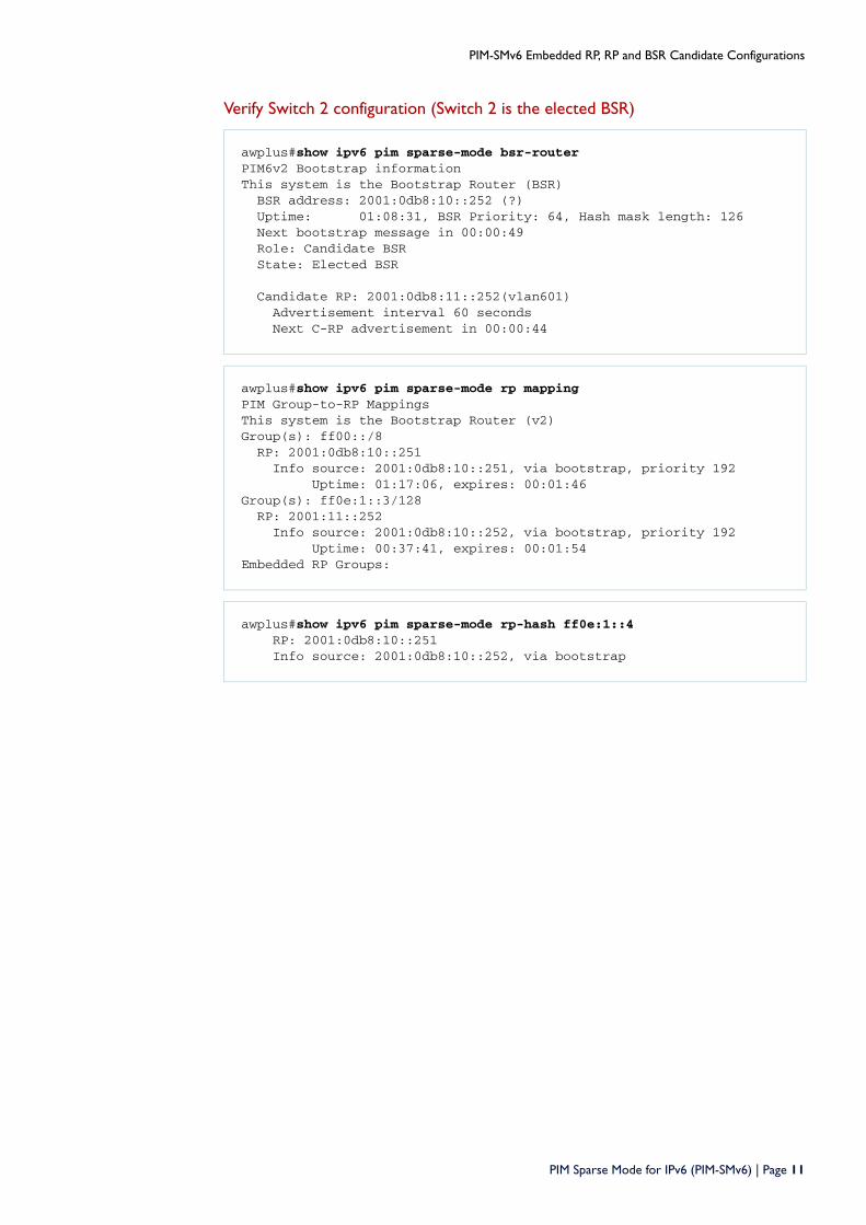
Verify Switch 2 configuration (Switch 2 is the elected BSR)
awplus#show ipv6 pim sparse-mode bsr-router PIM6v2 Bootstrap information This system is the Bootstrap Router (BSR) BSR address: 2001:0db8:10::252 (?) Uptime: 01:08:31, BSR Priority: 64, Hash mask length: 126 Next bootstrap message in 00:00:49 Role: Candidate BSR State: Elected BSR Candidate RP: 2001:0db8:11::252(vlan601) Advertisement interval 60 seconds Next C-RP advertisement in 00:00:44
awplus#show ipv6 pim sparse-mode rp mapping PIM Group-to-RP Mappings This system is the Bootstrap Router (v2) Group(s): ff00::/8 RP: 2001:0db8:10::251 Info source: 2001:0db8:10::251, via bootstrap, priority 192 Uptime: 01:17:06, expires: 00:01:46 Group(s): ff0e:1::3/128 RP: 2001:11::252 Info source: 2001:0db8:10::252, via bootstrap, priority 192 Uptime: 00:37:41, expires: 00:01:54 Embedded RP Groups:
awplus#show ipv6 pim sparse-mode rp-hash ff0e:1::4 RP: 2001:0db8:10::251 Info source: 2001:0db8:10::252, via bootstrap
PIM Sparse Mode for IPv6 (PIM-SMv6) | Page 11
PIM-SMv6 Static RP, DR, BSR Configurations
PIM-SMv6 Static RP, DR, BSR Configurations This section provides three PIM-SMv6 configuration examples:
Static Rendezvous Point configuration
Dynamic Rendezvous Point configuration
Boot Strap Router configuration
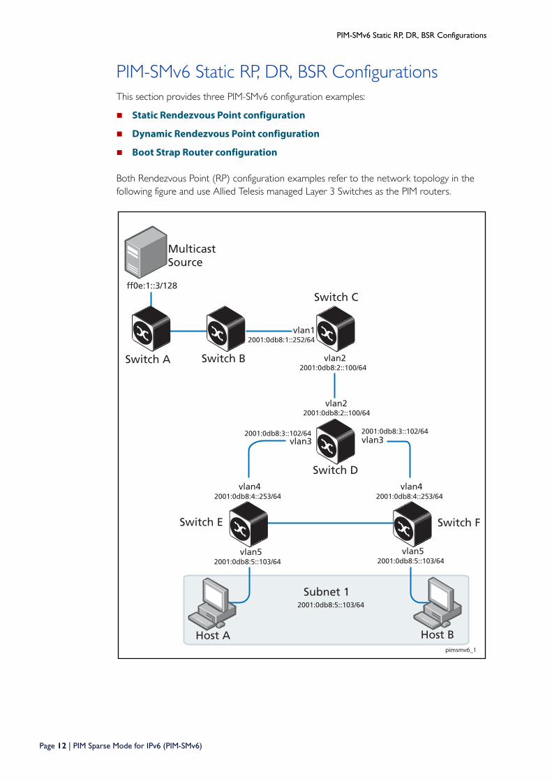
Both Rendezvous Point (RP) configuration examples refer to the network topology in the following figure and use Allied Telesis managed Layer 3 Switches as the PIM routers.
pimsmv6_1
Host A Host B
Switch E
Switch C
vlan22001:0db8:2::100/64
vlan52001:0db8:5::103/64
vlan52001:0db8:5::103/64
Switch F
vlan32001:0db8:3::102/64
Switch D
vlan2 2001:0db8:2::100/64
Switch BSwitch A
Subnet 12001:0db8:5::103/64
MulticastSource
vlan42001:0db8:4::253/64
vlan12001:0db8:1::252/64
ff0e:1::3/128
vlan32001:0db8:3::102/64
vlan42001:0db8:4::253/64
Page 12 | PIM Sparse Mode for IPv6 (PIM-SMv6)
PIM-SMv6 Static RP, DR, BSR Configurations
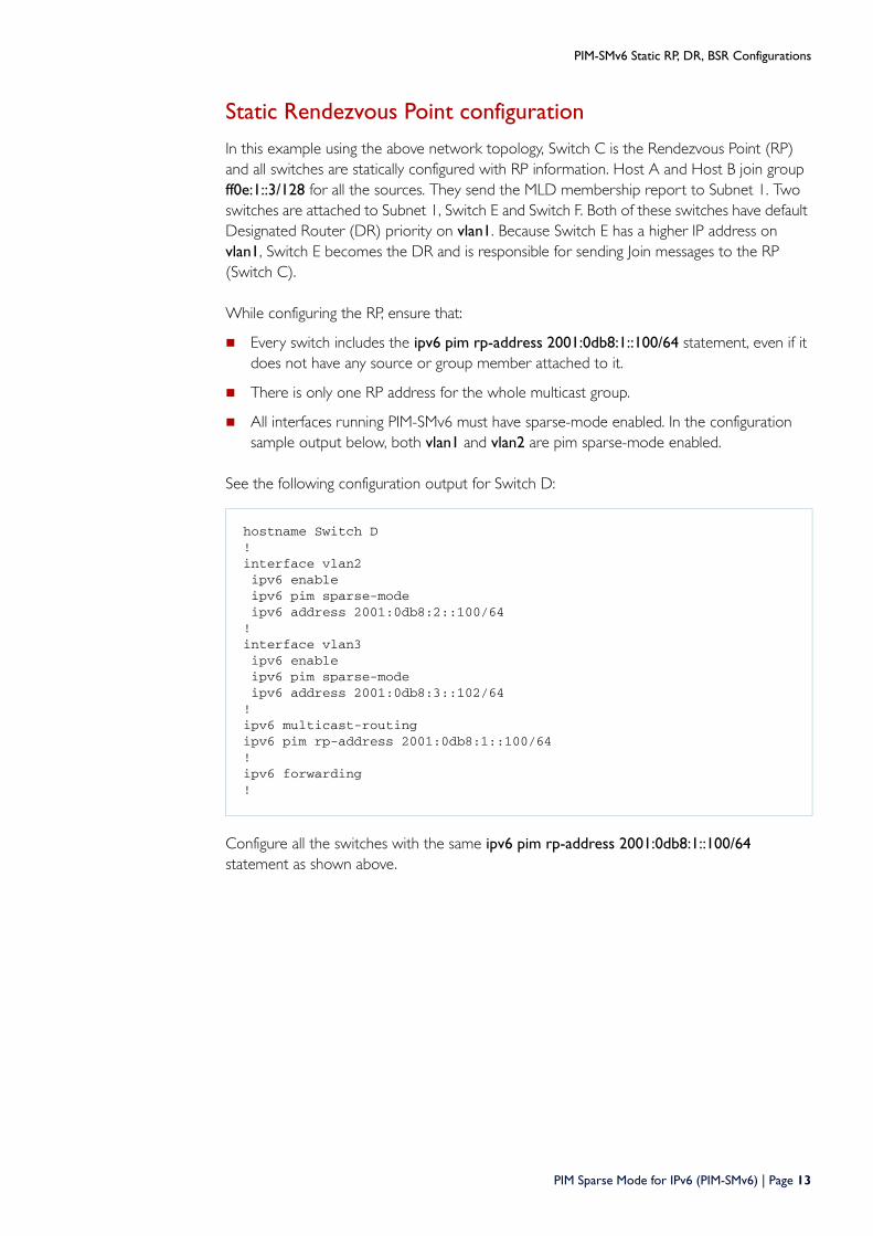
Static Rendezvous Point configuration
In this example using the above network topology, Switch C is the Rendezvous Point (RP) and all switches are statically configured with RP information. Host A and Host B join group ff0e:1::3/128 for all the sources. They send the MLD membership report to Subnet 1. Two switches are attached to Subnet 1, Switch E and Switch F. Both of these switches have default Designated Router (DR) priority on vlan1. Because Switch E has a higher IP address on vlan1, Switch E becomes the DR and is responsible for sending Join messages to the RP (Switch C).
While configuring the RP, ensure that:
Every switch includes the ipv6 pim rp-address 2001:0db8:1::100/64 statement, even if it does not have any source or group member attached to it.
There is only one RP address for the whole multicast group.
All interfaces running PIM-SMv6 must have sparse-mode enabled. In the configuration sample output below, both vlan1 and vlan2 are pim sparse-mode enabled.
See the following configuration output for Switch D:
Configure all the switches with the same ipv6 pim rp-address 2001:0db8:1::100/64 statement as shown above.
hostname Switch D!interface vlan2 ipv6 enable ipv6 pim sparse-mode ipv6 address 2001:0db8:2::100/64!interface vlan3 ipv6 enable ipv6 pim sparse-mode ipv6 address 2001:0db8:3::102/64!ipv6 multicast-routingipv6 pim rp-address 2001:0db8:1::100/64!ipv6 forwarding!
PIM Sparse Mode for IPv6 (PIM-SMv6) | Page 13
PIM-SMv6 Static RP, DR, BSR Configurations
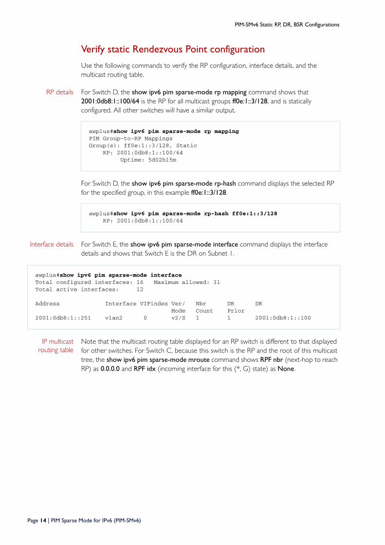
Verify static Rendezvous Point configuration
Use the following commands to verify the RP configuration, interface details, and the multicast routing table.
RP details For Switch D, the show ipv6 pim sparse-mode rp mapping command shows that 2001:0db8:1::100/64 is the RP for all multicast groups ff0e:1::3/128, and is statically configured. All other switches will have a similar output.
For Switch D, the show ipv6 pim sparse-mode rp-hash command displays the selected RP for the specified group, in this example ff0e:1::3/128.
Interface details For Switch E, the show ipv6 pim sparse-mode interface command displays the interface details and shows that Switch E is the DR on Subnet 1.
IP multicast routing table
Note that the multicast routing table displayed for an RP switch is different to that displayed for other switches. For Switch C, because this switch is the RP and the root of this multicast tree, the show ipv6 pim sparse-mode mroute command shows RPF nbr (next-hop to reach RP) as 0.0.0.0 and RPF idx (incoming interface for this (*, G) state) as None.
awplus#show ipv6 pim sparse-mode rp mapping PIM Group-to-RP MappingsGroup(s): ff0e:1::3/128, Static RP: 2001:0db8:1::100/64 Uptime: 5d02h15m
awplus#show ipv6 pim sparse-mode rp-hash ff0e:1::3/128 RP: 2001:0db8:1::100/64
awplus#show ipv6 pim sparse-mode interface Total configured interfaces: 16 Maximum allowed: 31Total active interfaces: 12
Address Interface VIFindex Ver/ Nbr DR DR Mode Count Prior2001:0db8:1::251 vlan2 0 v2/S 1 1 2001:0db8:1::100
Page 14 | PIM Sparse Mode for IPv6 (PIM-SMv6)
PIM-SMv6 Static RP, DR, BSR Configurations
For Switch E, the show ipv6 pim sparse-mode mroute command displays the IP multicast routing table.
On Switch E, port1.0.2 is the incoming interface of the (*, G) entry, and port1.0.1 is on the outgoing interface list of the (*, G) entry. This means that there is a group member through port1.0.1, and RP is reachable through port1.0.2.
awplus#show ipv6 pim sparse-mode mroute IP Multicast Routing Table
(*,*,RP) Entries: 0(*,G) Entries: 1(S,G) Entries: 0(S,G,rpt) Entries: 0(*, ff0e:1::3/128)RP: 2001:0db8:1::100/64RPF nbr: 0.0.0.0RPF idx: NoneUpstream State: JOINED Local ................................ Joined j............................... Asserted ................................ Outgoing o...............................
awplus#show ipv6 pim sparse-mode mroute IP Multicast Routing Table
(*,*,RP) Entries: 0(*,G) Entries: 1(S,G) Entries: 0(S,G,rpt) Entries: 0(*, ff0e:1::3/128)RP: 2001:0db8:1::100/64RPF nbr: 2001:0db8:1::100/64RPF idx: port1.0.2Upstream State: JOINED Local ................................ Joined j............................... Asserted ................................ Outgoing o...............................
PIM Sparse Mode for IPv6 (PIM-SMv6) | Page 15
PIM-SMv6 Static RP, DR, BSR Configurations
Dynamic Rendezvous Point configuration
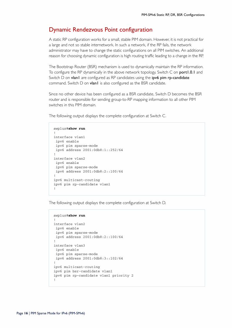
A static RP configuration works for a small, stable PIM domain. However, it is not practical for a large and not so stable internetwork. In such a network, if the RP fails, the network administrator may have to change the static configurations on all PIM switches. An additional reason for choosing dynamic configuration is high routing traffic leading to a change in the RP.
The Bootstrap Router (BSR) mechanism is used to dynamically maintain the RP information. To configure the RP dynamically in the above network topology, Switch C on port1.0.1 and Switch D on vlan1 are configured as RP candidates using the ipv6 pim rp-candidate command. Switch D on vlan1 is also configured as the BSR candidate.
Since no other device has been configured as a BSR candidate, Switch D becomes the BSR router and is responsible for sending group-to-RP mapping information to all other PIM switches in this PIM domain.
The following output displays the complete configuration at Switch C.
The following output displays the complete configuration at Switch D.
awplus#show run!interface vlan1 ipv6 enable ipv6 pim sparse-mode ipv6 address 2001:0db8:1::252/64!interface vlan2 ipv6 enable ipv6 pim sparse-mode ipv6 address 2001:0db8:2::100/64!ipv6 multicast-routingipv6 pim rp-candidate vlan1 !
awplus#show run!interface vlan2 ipv6 enable ipv6 pim sparse-mode ipv6 address 2001:0db8:2::100/64!interface vlan3 ipv6 enable ipv6 pim sparse-mode ipv6 address 2001:0db8:3::102/64!ipv6 multicast-routingipv6 pim bsr-candidate vlan1ipv6 pim rp-candidate vlan1 priority 2!
Page 16 | PIM Sparse Mode for IPv6 (PIM-SMv6)
PIM-SMv6 Static RP, DR, BSR Configurations
The highest priority switch is chosen as the RP. If two or more switches have the same priority, a hash function in the BSR mechanism is used to choose the RP to make sure that all devices in the PIM domain have the same RP for the same multicast group.
Use the <interface> priority <priority> parameters of the ipv6 pim rp-candidate command to change the default priority of any RP candidate.
Verify PIM group-to-RP mappings
The show ipv6 pim sparse-mode rp mapping command displays the group-to-RP mapping details. The output shows information about RP candidates. There are two RP candidates for the group range ff0e:1::3/128. RP candidate 2001:1::100/64 has a default priority of 192, whereas RP candidate 2001:1::251/64 has been configured to have a priority of 2. Since RP candidate 2001:1::251/64 has a higher priority, it is selected as the RP for the multicast group ff0e:1::3/128.
See the following configuration output for Switch D.
Verify RP details
The show ipv6 pim sparse-mode rp-hash command displays information about the RP router for a particular group. See the following configuration output for Switch D. This output shows that 2001:0db8:1::251/64 has been chosen as the RP for the multicast group ff0e:1::3/128.
After RP information reaches all PIM switches in the domain, various state machines maintain all routing states as the result of Join/Prune messages from members of the multicast group.
awplus#show ipv6 pim sparse-mode rp mapping This system is the Bootstrap Router (v2)Group(s): ff0e:1::3/128 RP: 2001:0db8:1::100/64 Info source: 2001:0db8:1::251/64, via bootstrap, priority 192 Uptime: 00:00:13, expires: 00:02:29
awplus#show ipv6 pim sparse-mode rp-hash ff0e:1::3/128 Group(s): ff0e:1::3/128 RP: 2001:0db8:1::251/64 Info source: 2001:0db8:1::251/64, via bootstrap
PIM Sparse Mode for IPv6 (PIM-SMv6) | Page 17
PIM-SMv6 Static RP, DR, BSR Configurations
Boot Strap Router configurationEvery PIM multicast group needs to be associated with the IP address of a Rendezvous Point (RP). This address is used as the root of a group-specific distribution tree, whose branches extend to all nodes in the domain that want to receive traffic sent to the group. For all senders to reach all receivers, all devices in the domain use the same mappings of group addresses to RP addresses. In order to determine the RP for a multicast group, a PIM device maintains a collection of group-to-RP mappings, called the RP-Set.
The BSR mechanism is one way that a multicast router can learn the set of group-to-RP mappings required in order to function.
Some of the PIM devices within a PIM domain are configured as RP candidates. A subset of the RP candidates will eventually be used as the actual RPs for the domain. An RP configured with a lower value in the priority field has higher a priority.
Some of the PIM devices in the domain are configured to be BSR candidates. One of these BSR candidates is elected to be the BSR for the domain, and all PIM devices in the domain learn the result of this election through Bootstrap messages (BSM). The BSR candidate with highest value in the priority field is the elected BSR.
The RP candidates then report their candidacy to the elected BSR, which chooses a subset of the RP candidates, and distributes corresponding group-to-RP mappings to all the devices in the domain through Bootstrap messages.
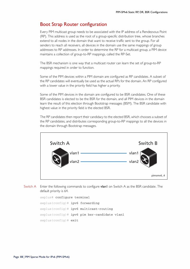
Switch A Enter the following commands to configure vlan1 on Switch A as the BSR candidate. The default priority is 64.
awplus# configure terminal
awplus(config)# ipv6 forwarding
awplus(config)# ipv6 multicast-routing
awplus(config)# ipv6 pim bsr-candidate vlan1
awplus(config)# exit
pimsmv6_4
Switch A Switch B
vlan1 vlan1
vlan2 vlan2
Page 18 | PIM Sparse Mode for IPv6 (PIM-SMv6)
PIM-SMv6 Static RP, DR, BSR Configurations
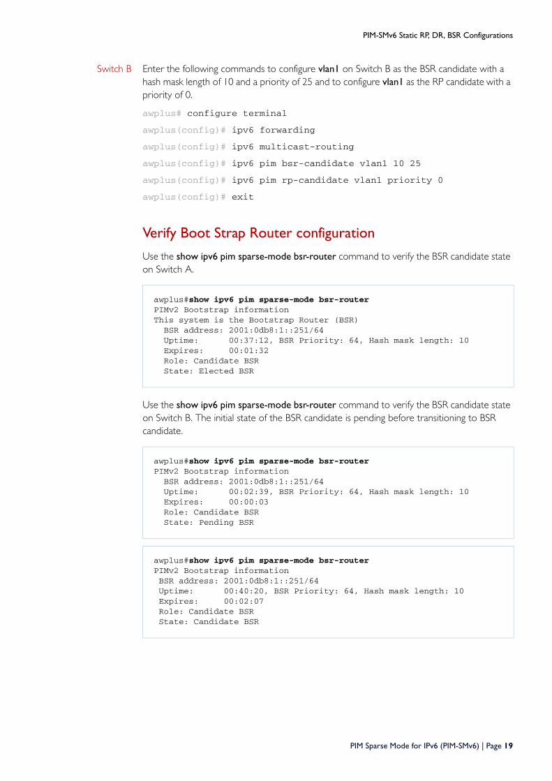
Switch B Enter the following commands to configure vlan1 on Switch B as the BSR candidate with a hash mask length of 10 and a priority of 25 and to configure vlan1 as the RP candidate with a priority of 0.
awplus# configure terminal
awplus(config)# ipv6 forwarding
awplus(config)# ipv6 multicast-routing
awplus(config)# ipv6 pim bsr-candidate vlan1 10 25
awplus(config)# ipv6 pim rp-candidate vlan1 priority 0
awplus(config)# exit
Verify Boot Strap Router configuration
Use the show ipv6 pim sparse-mode bsr-router command to verify the BSR candidate state on Switch A.
Use the show ipv6 pim sparse-mode bsr-router command to verify the BSR candidate state on Switch B. The initial state of the BSR candidate is pending before transitioning to BSR candidate.
awplus#show ipv6 pim sparse-mode bsr-routerPIMv2 Bootstrap informationThis system is the Bootstrap Router (BSR) BSR address: 2001:0db8:1::251/64 Uptime: 00:37:12, BSR Priority: 64, Hash mask length: 10 Expires: 00:01:32 Role: Candidate BSR State: Elected BSR
awplus#show ipv6 pim sparse-mode bsr-routerPIMv2 Bootstrap information BSR address: 2001:0db8:1::251/64 Uptime: 00:02:39, BSR Priority: 64, Hash mask length: 10 Expires: 00:00:03 Role: Candidate BSR State: Pending BSR
awplus#show ipv6 pim sparse-mode bsr-routerPIMv2 Bootstrap information BSR address: 2001:0db8:1::251/64 Uptime: 00:40:20, BSR Priority: 64, Hash mask length: 10 Expires: 00:02:07 Role: Candidate BSR State: Candidate BSR
PIM Sparse Mode for IPv6 (PIM-SMv6) | Page 19

Use the show ipv6 pim sparse-mode rp mapping command to verify RP-set information on Switch A.
Use the show ipv6 pim sparse-mode rp mapping command to verify RP-set information on Switch B.
awplus#show ipv6 pim sparse-mode rp mappingPIM Group-to-RP MappingsThis system is the Bootstrap Router (v2)Group(s): ff0e:1::3/128 RP: 2001:db8:1::251/64 Info source: 2001:db8:1::251/64, via bootstrap, priority 0 Uptime: 00:00:30, expires: 00:02:04
awplus#show ipv6 pim sparse-mode rp mappingPIM Group-to-RP MappingsGroup(s): ff0e:1::3/128 RP: 2001:db8:1::251/64 Info source: 2001:db8:1::251/64, via bootstrap, priority 0 Uptime: 00:00:12, expires: 00:02:18
C613-22036-00 REV A
North America Headquarters | 19800 North Creek Parkway | Suite 100 | Bothell | WA 98011 | USA | T: +1 800 424 4284 | F: +1 425 481 3895Asia-Pacifi c Headquarters | 11 Tai Seng Link | Singapore | 534182 | T: +65 6383 3832 | F: +65 6383 3830EMEA & CSA Operations | Incheonweg 7 | 1437 EK Rozenburg | The Netherlands | T: +31 20 7950020 | F: +31 20 7950021
alliedtelesis.com© 2015 Allied Telesis Inc. All rights reserved. Information in this document is subject to change without notice. All company names, logos, and product designs that are trademarks or registered trademarks are the property of their respective owners.