electromagnetic properties part i. electrical and magnetic properties electromagnetic fields are...
TRANSCRIPT
Electromagnetic properties
Part I
Electrical and magnetic properties
• Electromagnetic fields are propagated through and reflected by materials– Characterized as:
• Current flow at low frequencies
• Magnetism in metals
• Optical absorbance / reflectance in light
• etc.
• Frequency is a major factor in the primary characteristics– Low frequency – “electrical” properties– High frequency – “optical” properties
Fundamentals of high frequency electromagnetic waves (Light)
• Light = Energy (radiant energy)– Readily converted to heat
• Light shining on a surface heats the surface
• Heat = energy
• Light = Electro-magnetic phenomena– Has the characteristics of electromagnetic waves (eg. radio
waves)– Also behaves like particles (e.g.. photons)
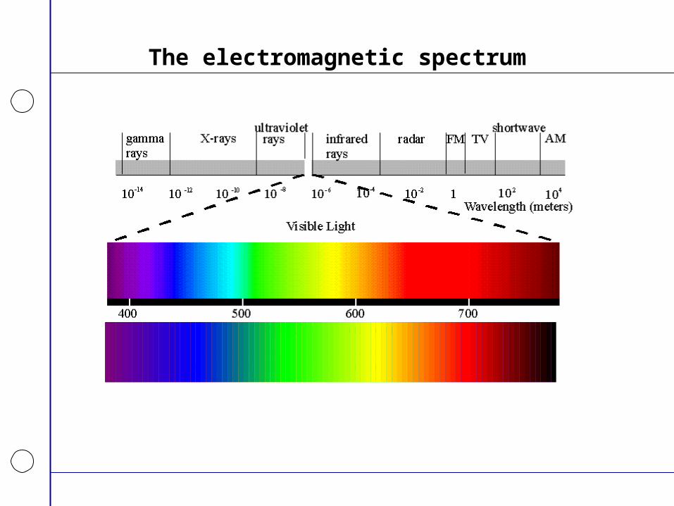
The electromagnetic spectrum
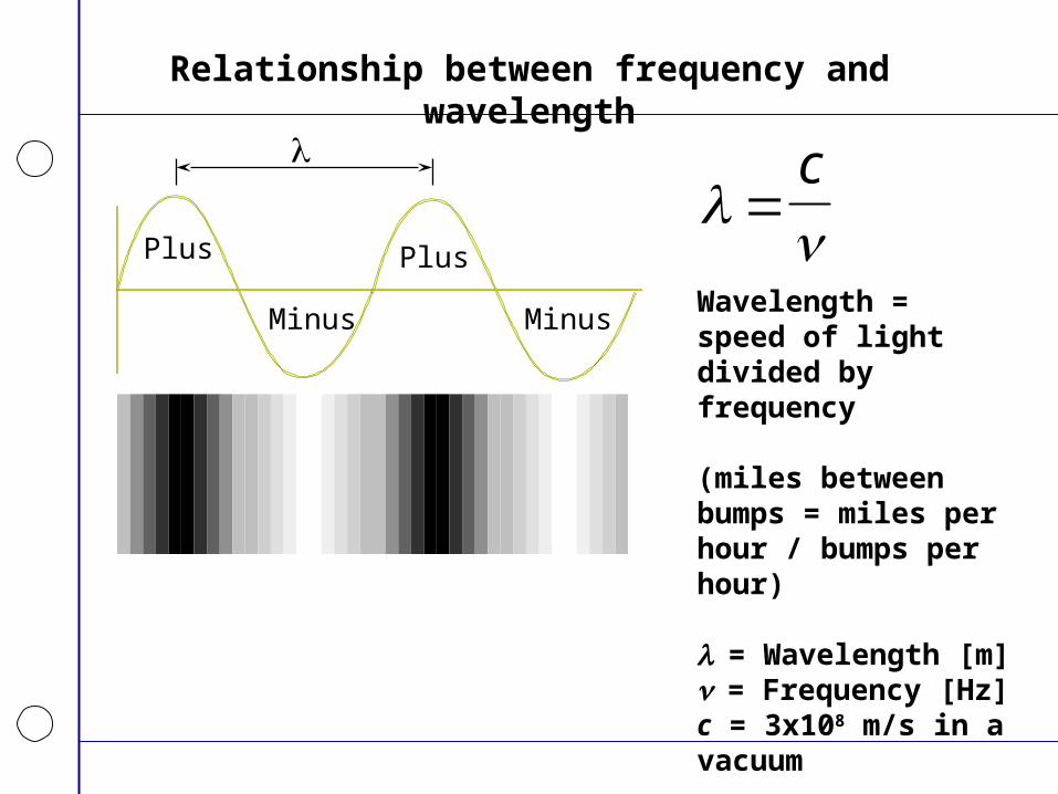
Relationship between frequency and wavelength
Plus
Minus Minus
Plus
Wavelength = speed of light divided by frequency
(miles between bumps = miles per hour / bumps per hour)
= Wavelength [m]= Frequency [Hz]c = 3x10⁸ m/s in a vacuum
c
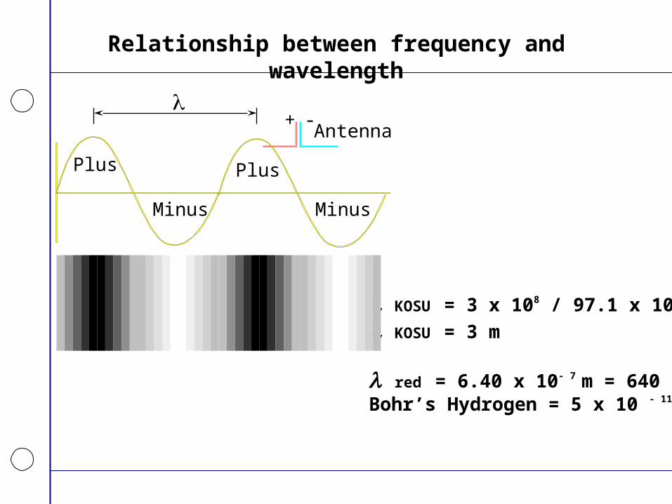
Relationship between frequency and wavelength
Plus
Minus Minus
Plus
Antenna
+ -
KOSU = 3 x 10⁸ / 97.1 x 10⁶
KOSU = 3 m
red = 6.40 x 10- 7 m = 640 nmBohr’s Hydrogen = 5 x 10 - 11 m
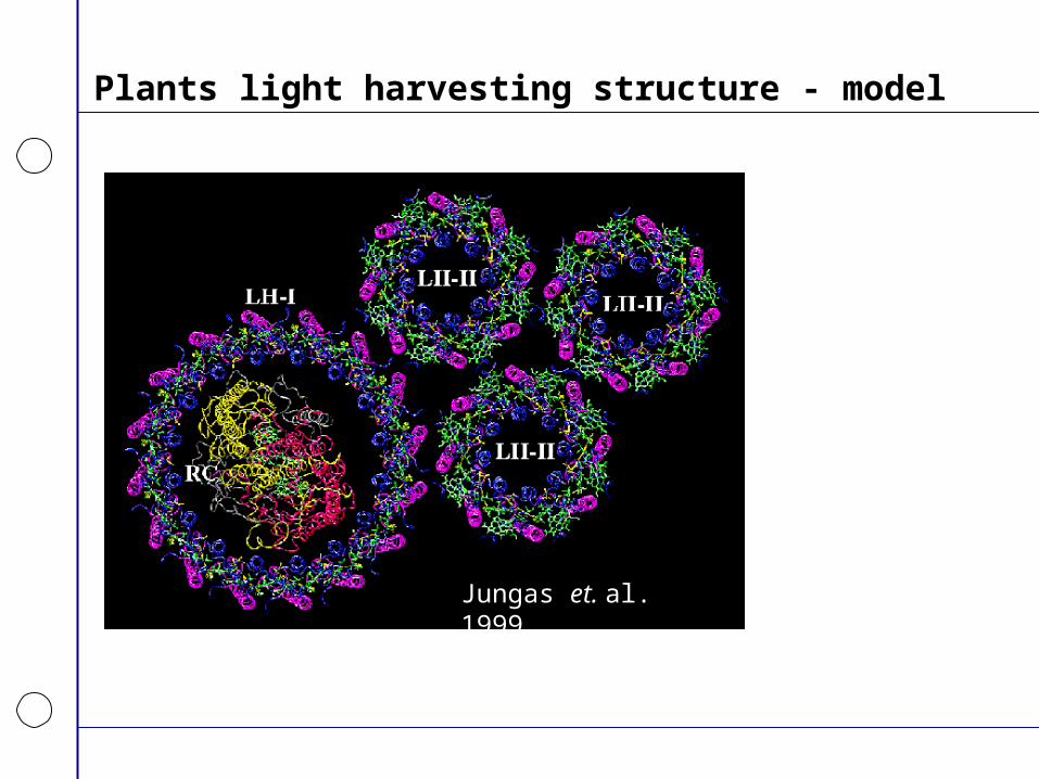
Plants light harvesting structure - model
Jungas et. al. 1999
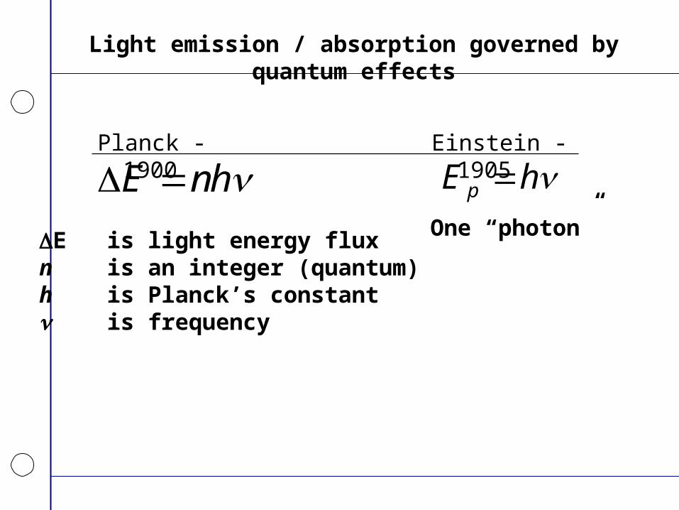
Light emission / absorption governed by quantum effects
Planck - 1900
E nh E is light energy fluxn is an integer (quantum)h is Planck’s constant is frequency
E hp Einstein - 1905
One “photon”
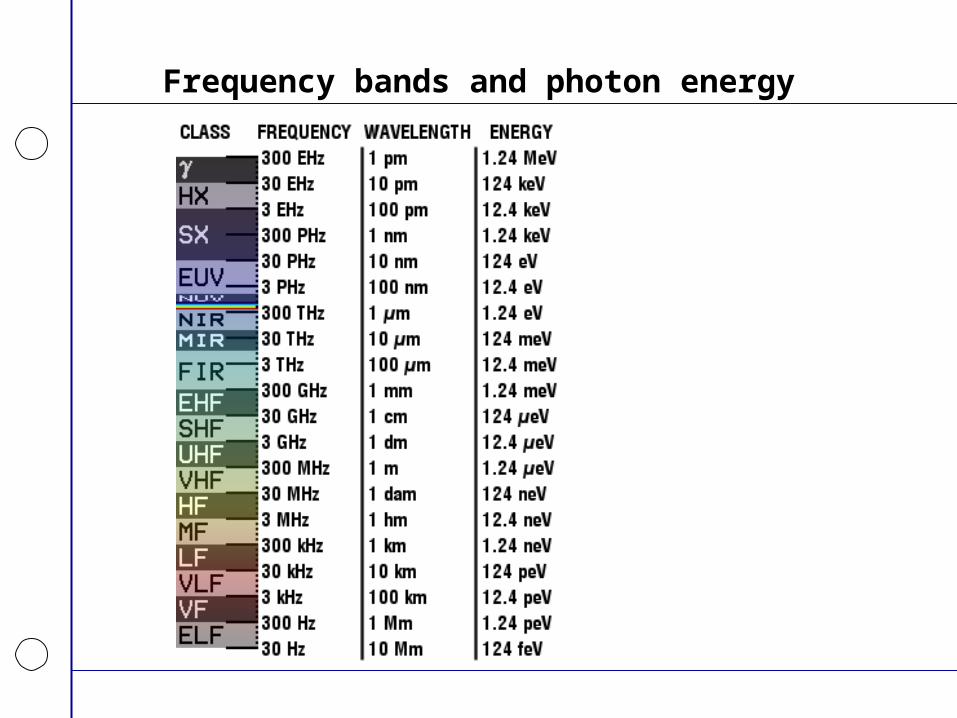
Frequency bands and photon energy
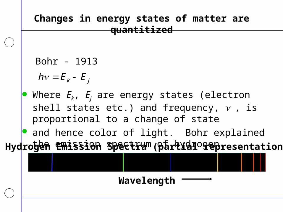
Changes in energy states of matter are quantitized
Bohr - 1913
h E Ek j
Where Ek, Ej are energy states (electron shell states etc.) and frequency, , is proportional to a change of state
and hence color of light. Bohr explained the emission spectrum of hydrogen.
Hydrogen Emission Spectra (partial representation)
Wavelength
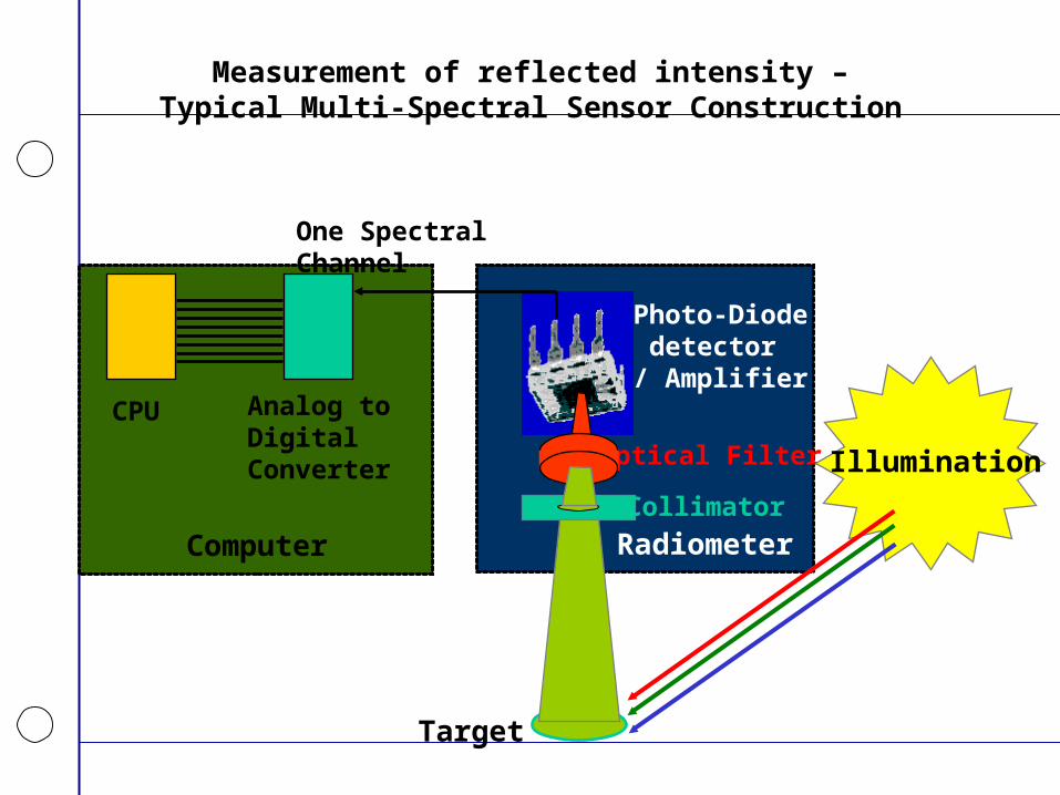
Measurement of reflected intensity –Typical Multi-Spectral Sensor Construction
Analog toDigitalConverter
Computer
One Spectral Channel
Photo-Diode detector/ Amplifier
Optical Filter
Collimator
Target
Illumination
CPU
Radiometer
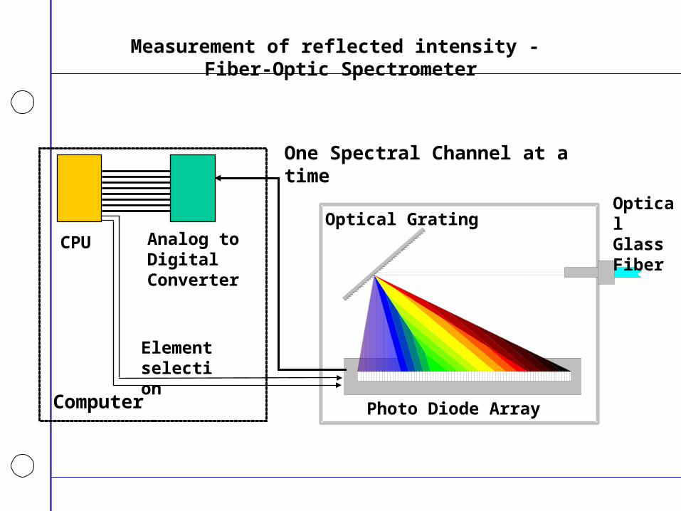
Measurement of reflected intensity - Fiber-Optic Spectrometer
OpticalGlass Fiber
Photo Diode Array
Optical GratingAnalog toDigitalConverter
Computer
CPU
Element selection
One Spectral Channel at a time
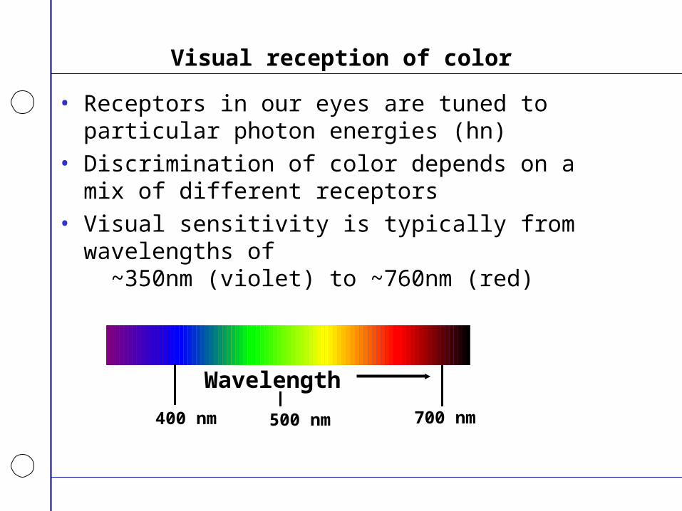
Visual reception of color
• Receptors in our eyes are tuned to particular photon energies (hn)
• Discrimination of color depends on a mix of different receptors
• Visual sensitivity is typically from wavelengths of ~350nm (violet) to ~760nm (red)
Wavelength
400 nm 700 nm500 nm
Quantification of color
• Spectral measurements can be used to quantify reflected light in energy and spectral content, but not very useful description of what we see.
• Tri-stimulus models – represent color as perceived by humans– Tri-stimulus models
• RGB - most digital work
• CYM - print
• HSI, HSB, or HSV - artists
• CIE L*a*b*
• YUV and YIQ - television broadcasts
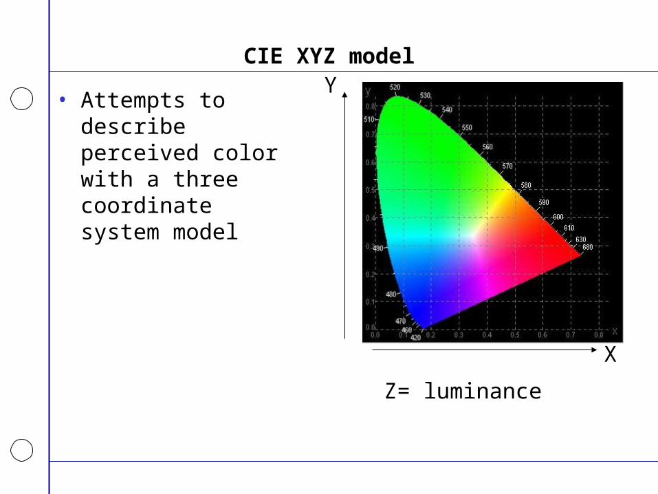
CIE XYZ model
• Attempts to describe perceived color with a three coordinate system model
X
Y
Z= luminance

CIE Lab model
• An improvement of the CIE XYZ color model.
• Three dimensional model where color differences correspond to distances measured colorimetrically
• Hue and saturation (a, b) – a axis extends from green (-a) to red (+a)– b axis from blue (-b) to yellow (+b)
• Luminance (L) increases from the bottom to the top of the three-dimensional model
• Colors are represented by numerical values
• Hue can be changed without changing the image or its luminance.
• Can be converted to or from RGB or other tri-stimulus models
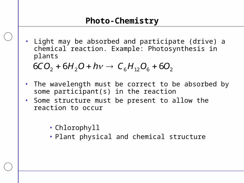
Photo-Chemistry
• Light may be absorbed and participate (drive) a chemical reaction. Example: Photosynthesis in plants
6 6 62 2 6 12 6 2CO H O h C H O O
• The wavelength must be correct to be absorbed by some participant(s) in the reaction
• Some structure must be present to allow the reaction to occur
• Chlorophyll• Plant physical and chemical structure
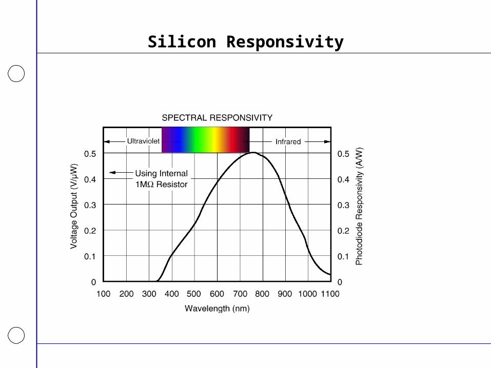
Silicon Responsivity
Primary and secondary absorbers in plants
• Primary– Chlorophyll-a– Chlorophyll-b
• Secondary– Carotenoids– Phycobilins– Anthocyanins
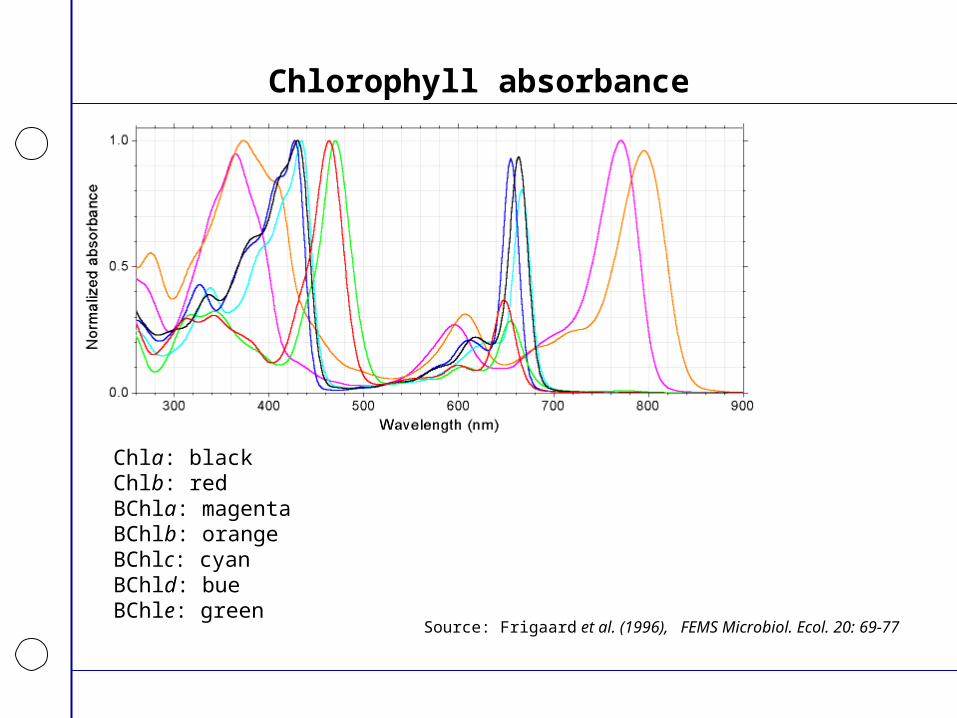
Chlorophyll absorbance
Chla: blackChlb: redBChla: magentaBChlb: orangeBChlc: cyanBChld: bueBChle: green
Source: Frigaard et al. (1996), FEMS Microbiol. Ecol. 20: 69-77
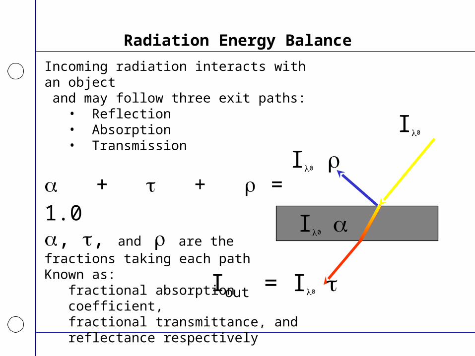
Radiation Energy Balance
Incoming radiation interacts with an object and may follow three exit paths:
• Reflection• Absorption• Transmission
+ + = 1.0, , and are thefractions taking each pathKnown as:
fractional absorption coefficient,fractional transmittance, andreflectance respectively
I0
I0 I0
Iout = I0
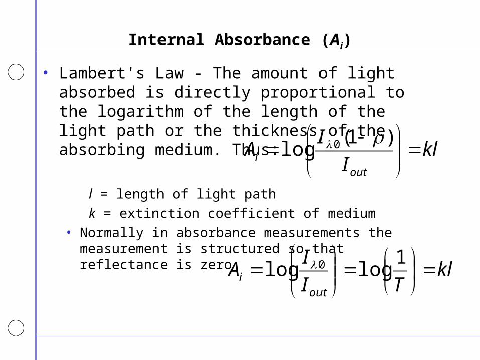
Internal Absorbance (Ai)
• Lambert's Law - The amount of light absorbed is directly proportional to the logarithm of the length of the light path or the thickness of the absorbing medium. Thus:
l = length of light path
k = extinction coefficient of medium• Normally in absorbance measurements the measurement is
structured so that reflectance is zero
klI
IA
outi
)1(log 0
klTI
IA
outi
1loglog 0
Reflectance
– Ratio of incoming to reflected irradiance– Incoming can be measured using a “white” reflectance target– Reflectance is not a function of incoming irradiance level or
spectral content, but of target characteristics
0
100
200
300
400
500
600
700
0 250 500 750 1000 1250 1500 1750 2000Wavelength (nm)
Sp
ectr
al Irr
adie
nce
(w
/m^2
nm
)
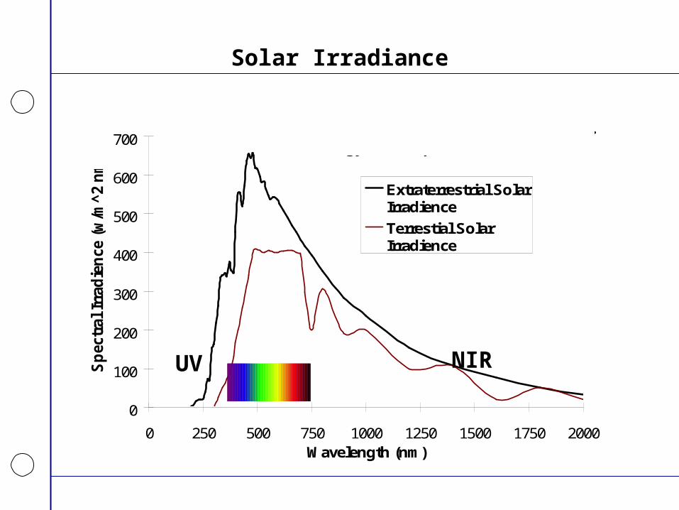
Extraterrestrial SolarIrradience
Terrestial SolarIrradience
Adapted from Thekaekara, M. P. 1973.Solar Energy Outside the Earth's Atmosphere.Solar Energy, Vol 14, p 109.
Solar Irradiance
NIRUV
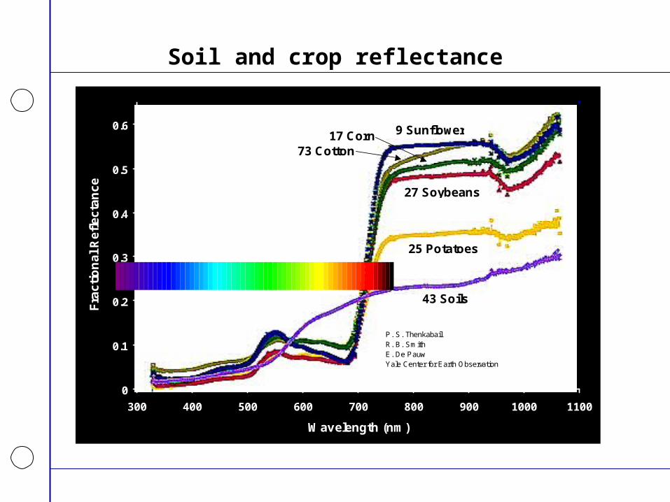
Soil and crop reflectance
0
0.1
0.2
0.3
0.4
0.5
0.6
300 400 500 600 700 800 900 1000 1100
Wavelength (nm)
Fra
cti
on
al
Re
fle
cta
nc
e
43 Soils
27 Soybeans
25 Potatoes
9 Sunflower
73 Cotton17 Corn
P. S. ThenkabailR. B. SmithE. De PauwYale Center for Earth Observation

Soil Reflectances - Oklahoma
0
0.2
0.4
0.6
0.8
1
350 400 450 500 550 600 650 700 750 800
Wavelength (nm)
Ref
lect
ance
(Fra
ctio
n)Tipton Stillwater
Perkins Mangum
Lahoma Haskell
Goodwell Ft. Cobb
Chickasha Altus
Agron. Stwr.
Electrical properties - Current and Voltage
• Current:– Flow of electrons
• The quantity of electrons per unit time flowing through a conducting medium
• Units Amperes (A), abbreviated “amps“ or fundamentally coulombs per second (coulomb=6.03x10²³ electrons)
• Voltage:– Electromotive force (EMF)
• A potential or “tension” between two points of a conducting medium that can drive the flow of electrons through the medium expressed as work per number of electrons
• Analogous to pressure in a fluid that can drive flow of fluid through a pipe
• Units of Volts (V) or fundamentally joules per coulomb, the energy (potential) per unit of electrons.
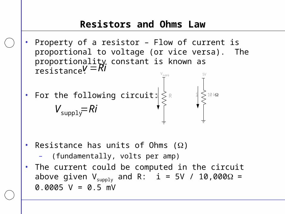
Resistors and Ohms Law
• Property of a resistor – Flow of current is proportional to voltage (or vice versa). The proportionality constant is known as resistance:
• For the following circuit:
• Resistance has units of Ohms ()– (fundamentally, volts per amp)
• The current could be computed in the circuit above given Vsupply and R: i = 5V / 10,000= 0.0005 V = 0.5 mV
Riv
RiV supply
5V
10 kii
Vsupply
R
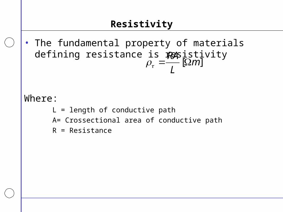
Resistivity
• The fundamental property of materials defining resistance is resistivity
Where:L = length of conductive path
A= Crossectional area of conductive path
R = Resistance
][ mL
RA