electromagnetic emissions compliance report intentional ... · trf no:fcc 15.247/a page 1 of 52...
TRANSCRIPT

TRF No:FCC 15.247/A Page 1 of 52 Report No ES140625234E1
ELECTROMAGNETIC EMISSIONS COMPLIANCE REPORT INTENTIONAL RADIATOR CERTIFICATION TO
FCC PART 15 SUBPART C REQUIREMENTS
OF
LIFX GU10 Wi-Fi Downlight
MODEL No.: BUL-11-GU10-G
FCC ID: 2AA53-LIFX02
Trade Mark: LIFX
REPORT NO: ES140625234E1
ISSUE DATE: July 31, 2014
Prepared for LIFI LABS INC
524 Union Street #309, San Francisco, CA,USA, 94133
Prepared by SHENZHEN EMTEK CO., LTD
Bldg 69, Majialong Industry Zone, Nanshan District, Shenzhen, Guangdong, China
TEL: 86-755-26954280 FAX: 86-755-26954282

TRF No:FCC 15.247/A Page 2 of 52 Report No ES140625234E1
VERIFICATION OF COMPLIANCE Applicant: LIFI LABS INC
524 Union Street #309, San Francisco, CA,USA, 94133 Manufacturer: LIFI LABS INC
524 Union Street #309, San Francisco, CA,USA, 94133
Product Description: LIFX GU10 Wi-Fi Downlight
Model Number: BUL-11-GU10-G
File Number: ES140625234E1
Date of Test: July 23, 2014 to July 31, 2014
We hereby certify that:
The above equipment was tested by SHENZHEN EMTEK CO., LTD. The test data, data evaluation, test procedures, and equipment configurations shown in this report were made in accordance with the procedures given in ANSI C63.4 (2009) and the energy emitted by the sample EUT tested as described in this report is in compliance with conducted and radiated emission limits of FCC Rules Part 15.247 REQUIREMENTS The test results of this report relate only to the tested sample identified in this report. Date of Test : July 23, 2014 to July 31, 2014
Prepared by :
King Kong Xia/Editor
Reviewer :
Jack Li/Supervisor
Approve & Authorized Signer :
Lisa Wang/Manager

TRF No:FCC 15.247/A Page 3 of 52 Report No ES140625234E1
Table of Contents
1. General Information .............................................................................................................................................. 5
1.1 Product Description.......................................................................................................................................... 5 1.2 Related Submittal(s) / Grant(s) ........................................................................................................................ 5 1.3 Test Methodology ............................................................................................................................................ 6 1.4 Special Accessories .......................................................................................................................................... 6 1.5 Equipment Modifications ................................................................................................................................. 6 1.6 Test Facility ...................................................................................................................................................... 6
2. System Test Configuration ..................................................................................................................................... 7
2.1 EUT Configuration .......................................................................................................................................... 7 2.2 EUT Exercise ................................................................................................................................................... 7 2.3 Test Procedure .................................................................................................................................................. 7 2.4 Configuration of Tested System ....................................................................................................................... 7
3. Description of Test Modes ...................................................................................................................................... 9
4. Summary of Test Results ..................................................................................................................................... 10
N/A ................................................................................................................................................................................. 10
5. Conducted Emissions Test ................................................................................................................................... 11
5.1 Measurement Procedure ................................................................................................................................. 11 5.2 Test SET-UP (Block Diagram of Configuration) ........................................................................................... 11 5.3 Measurement Equipment Used ...................................................................................................................... 11 5.4 Conducted Emission Limit ............................................................................................................................. 11 5.5 Measurement Result ....................................................................................................................................... 12
6. Radiated Emission Test ........................................................................................................................................ 14
6.1 Measurement Procedure ................................................................................................................................. 14 6.2 Test SET-UP (Block Diagram of Configuration) ........................................................................................... 14 6.3 Measurement Equipment Used ...................................................................................................................... 15 6.4 Radiated Emission Limit ................................................................................................................................ 16 6.5 Measurement Result ....................................................................................................................................... 17
7. 6dB Bandwidth Test ............................................................................................................................................. 26
7.1 Measurement Procedure ................................................................................................................................. 26 7.2 Test SET-UP (Block Diagram of Configuration) ........................................................................................... 26 7.3 Measurement Equipment Used ...................................................................................................................... 26 7.4 Measurement Results ..................................................................................................................................... 26
8. Maximum Peak Output Power Test .................................................................................................................... 33
8.1 Measurement Procedure ................................................................................................................................. 33 8.2 Test SET-UP (Block Diagram of Configuration) ........................................................................................... 33 8.3 Measurement Equipment Used ...................................................................................................................... 33 8.4 Peak Power output limit ................................................................................................................................. 33 8.5 Measurement Results ..................................................................................................................................... 33
9. Band Edge Test ..................................................................................................................................................... 35
9.1 Measurement Procedure ................................................................................................................................. 35 9.2 Test SET-UP (Block Diagram of Configuration) ........................................................................................... 35 9.3 Measurement Equipment Used ...................................................................................................................... 35 9.4 Measurement Results ..................................................................................................................................... 35
10. Power Density ................................................................................................................................................... 40
10.1 Test Equipment .............................................................................................................................................. 40 10.2 Measuring Instruments and Setting ................................................................................................................ 40
TRF No:FCC 15.247/A Page 4 of 52 Report No ES140625234E1
10.3 Test Procedures .............................................................................................................................................. 40 10.4 Block Diagram of Test Setup ......................................................................................................................... 40 10.5 Limit ............................................................................................................................................................... 40 10.6 Test Result ...................................................................................................................................................... 41
11. Antenna Port Emission .................................................................................................................................... 47
11.1 Test Equipment .............................................................................................................................................. 47 11.2 Measuring Instruments and Setting ................................................................................................................ 47 11.3 Test Procedures .............................................................................................................................................. 47 11.4 Block Diagram of Test setup .......................................................................................................................... 47 11.5 Test Result ...................................................................................................................................................... 47
12. Antenna Application ........................................................................................................................................ 51
12.1 Antenna Requirement .................................................................................................................................... 51 12.2 Result ............................................................................................................................................................. 51
13. Uncertainty ....................................................................................................................................................... 52

TRF No:FCC 15.247/A Page 5 of 52 Report No ES140625234E1
1. General Information
1.1 Product Description
A major technical descriptions of EUT is described as following: A). Standards: IEEE802.11b/g/n, IEEE802.15.4 B). Operation Frequency: Zigbee: 2405-2480MHz, WIFI: 2412-2462MHz; C). Modulation: QPSK for Zigbee
OFDM with BPSK/QPSK/16QAM/64QAM for 802.11g/n, DSSS with DBPSK/DQPSK/CCK for 802.11b for Wifi
D). Number of Channel: Wifi: 11Channels; Zigbee: 16 Channels; D). Channel spacing:5MHz E).Conducted Power:-3.42dBm for Zigbee, 16.12dBm for Wifi F) Antenna Gain: 1.1dBi for Zigbee, 1.5dBi for Wifi G). Antenna Type: Chip Antenna H). Power Supply: AC 100-240V 0.15A 12.5W 50/60Hz
Channel Frequency
Channel Frequency
Channel Frequency
(MHz) (MHz) (MHz) 1 2412 5 2432 9 2452 2 2417 6 2437 10 2457 3 2422 7 2442 11 2462 4 2427 8 2447
Note: 1. This device is included Wifi and Zigbee transceiver function. 2. Test of channel was included the lowest middle and highest frequency in lowest data
rate and to perform the test, then record on this report.
1.2 Related Submittal(s) / Grant(s)
This submittal(s) (test report) is intended for FCC ID: 2AA53-LIFX02 filing to comply with Section 15.247 of the FCC Part 15, Subpart C Rules, The composite system is compliance with Subpart B is authorized under a DOC procedure.

TRF No:FCC 15.247/A Page 6 of 52 Report No ES140625234E1
1.3 Test Methodology
All the test program has follow FCC new test procedure KDB558074 D01 v03r01, Both conducted and radiated testing was performed according to the procedures in ANSI C63.10(2009). Radiated testing was performed at an antenna to EUT distance 3 meters.
1.4 Special Accessories
Not available for this EUT intended for grant.
1.5 Equipment Modifications
Not available for this EUT intended for grant.
1.6 Test Facility
Site Description EMC Lab. : Accredited by CNAS, 2013.10.29
The certificate is valid until 2016.10.28 The Laboratory has been assessed and proved to be in compliance with CNAS/CL01: 2006(identical to ISO/IEC17025: 2005) The Certificate Registration Number is L2291 Accredited by TUV Rheinland Shenzhen 2010.5.25 The Laboratory has been assessed according to the requirements ISO/IEC 17025
Accredited by FCC, April 17, 2013 The Certificate Registration Number is 406365. Accredited by Industry Canada, March 05, 2010 The Certificate Registration Number is 46405-4480.
Name of Firm : SHENZHEN EMTEK CO., LTD. Site Location : Bldg 69, Majialong Industry Zone,
Nanshan District, Shenzhen, Guangdong, China
TRF No:FCC 15.247/A Page 7 of 52 Report No ES140625234E1
2. System Test Configuration
2.1 EUT Configuration
The EUT configuration for testing is installed on RF field strength measurement to meet the Commissions requirement and operating in a manner which intends to maximize its emission characteristics in a continuous normal application.
2.2 EUT Exercise
The Transmitter was operated in the normal operating mode. The TX frequency was fixed which was for the purpose of the measurements.
2.3 Test Procedure
2.3.1 Conducted Emissions
The EUT is a placed on as turn table which is 0.8 m above ground plane. According to the requirements in Section 13.1.4.1 of ANSI C63.4-2009 Conducted emissions from the EUT measured in the frequency range between 0.15 MHz and 30 MHz using CISPR Quasi-Peak and average detector mode.
2.3.2 Radiated Emissions
The EUT is a placed on as turn table which is 0.8 m above ground plane. The turn table shall rotate 360 degrees to determine the position of maximum emission level. EUT is set 3m away from the receiving antenna which varied from 1m to 4m to find out the highest emission. And also, each emission was to be maximized by changing the polarization of receiving antenna both horizontal and vertical. In order to find out the max. Emission, the relative positions of this hand-held transmitter (EUT) was rotated through three orthogonal axes according to the requirements in Section 13.1.4.1 of ANSI C63.4-2009.
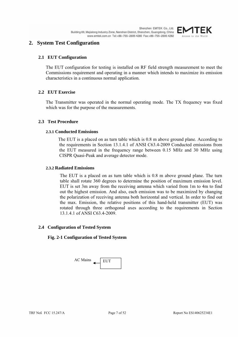
2.4 Configuration of Tested System
Fig. 2-1 Configuration of Tested System
AC Mains EUT

TRF No:FCC 15.247/A Page 8 of 52 Report No ES140625234E1
Table 2-1 Equipment Used in Tested System
Item Equipment Mfr/Brand Model/Type No. FCC ID Series No. Note
1.
LIFX GU10 Wi-Fi
Downlight
LIFX BUL-11-GU10-G 2AA53-LIFX02 N/A EUT
Note: (1) Unless otherwise denoted as EUT in『Remark』column, device(s) used in tested system is a
support equipment.
TRF No:FCC 15.247/A Page 9 of 52 Report No ES140625234E1
3. Description of Test Modes The Transmitter of EUT is an Mobile Internet Device and powered by host equipment; these is Digital Transmission system (DTS) and have modulation OFDM, DSSS, DBPSK, DQPSK, CCK, 16QAM, 64QAM. According exploratory test, EUT will have maximum output power in those data rate (802.11b: 1 Mbps; 802.11g: 6 Mbps; 802.11n: MCS0), so those data rate were used for all test. The equipment enables high-speed access without wires to network assets. This adapter uses the IEEE 802.11 protocol to enable wireless communications between the host and Wireless rooter. For 802.11b/g/n HT20: 1. For lowest channel : 2412MHz (Channel 1) 2. For middle channel : 2437MHz (Channel 6) 3. For highest channel : 2462MHz (Channel 11)

TRF No:FCC 15.247/A Page 10 of 52 Report No ES140625234E1
4. Summary of Test Results
FCC Rules Description Of Test Result §15.247(a)(2) 6dB bandwidth Pass §15.247(b)(3) Max Peak output Power test Pass
§15.247(e) Power density Pass §15.247(d) Band edge test Pass
§15.207 AC Power Conducted
Emission Pass
§15.247(d), §15.209 Radiated Emission Pass §15.247(d) Antenna Port Emission Pass
§15.247(b)&§15.203
Antenna Application Pass
N/A 99%dB Bandwidth Pass

TRF No:FCC 15.247/A Page 11 of 52 Report No ES140625234E1
EUT L.I.S.N
5. Conducted Emissions Test
5.1 Measurement Procedure
1. The EUT was placed on a table which is 0.8m above ground plane.
2. Maximum procedure was performed on the six highest emissions to ensure EUT compliance.
3. Repeat above procedures until all frequency measured were complete.
5.2 Test SET-UP (Block Diagram of Configuration)
5.3 Measurement Equipment Used
Conducted Emission Test Site EQUIPMENT
TYPE MFR MODEL
NUMBER SERIAL
NUMBER LAST CAL.
CAL DUE.
Test Receiver Rohde & Schwarz ESCS30 828985/018 05/17/2014 05/16/2015L.I.S.N. Schwarzbeck NNLK8129 8129203 05/17/2014 05/16/2015
50Ω Coaxial Switch
Anritsu MP59B M20531 N/A N/A
Pulse Limiter Rohde & Schwarz ESH3-Z2 100006 05/17/2014 05/16/2015Voltage Probe Rohde & Schwarz TK9416 N/A 05/17/2014 05/16/2015
I.S.N Rohde & Schwarz ENY22 1109.9508.02 05/17/2014 05/16/2015
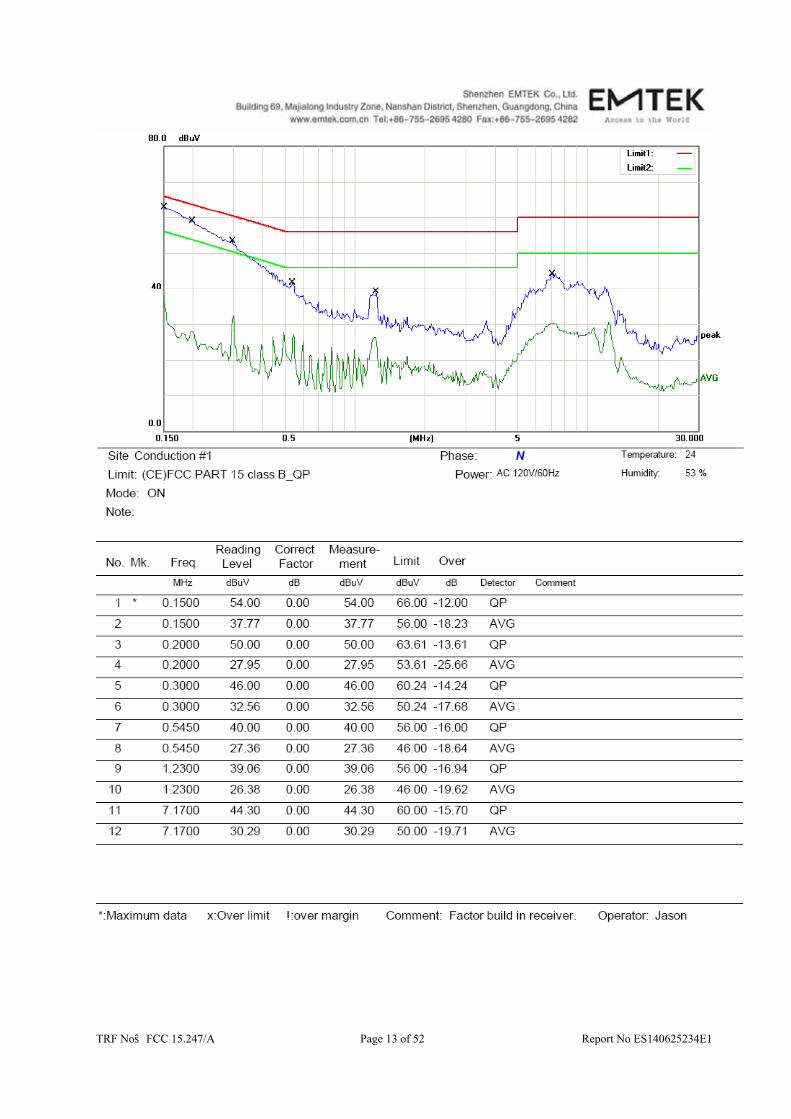
5.4 Conducted Emission Limit
Conducted Emission Frequency(MHz) Quasi-peak Average 0.15-0.5 66-56 56-46 0.5-5.0 56 46 5.0-30.0 60 50 Note: 1. The lower limit shall apply at the transition frequencies 2. The limit decreases in line with the logarithm of the frequency in the range of
0.15 to 0.50MHz.
AC Mains
Test Receiver

TRF No:FCC 15.247/A Page 12 of 52 Report No ES140625234E1
5.5 Measurement Result
TRF No:FCC 15.247/A Page 13 of 52 Report No ES140625234E1

TRF No:FCC 15.247/A Page 14 of 52 Report No ES140625234E1
6. Radiated Emission Test
6.1 Measurement Procedure When spectrum scanned from 30 MHz to 1GHz setting resolution bandwidth 120 kHz and video bandwidth 300kHz. EMI Test Receiver Setting Attenuation Auto RB 120kHz VB 300kHz Detector QP Trace Max hold
When spectrum scanned above 1GHz setting resolution bandwidth 1MHz, video bandwidth 3MHz. EMI Test Receiver Setting Attenuation Auto RB 1MHz VB 3MHz Detector Peak Trace Max hold
When spectrum scanned above 1GHz setting resolution bandwidth 1MHz, video bandwidth 10Hz. EMI Test Receiver Setting Attenuation Auto RB 1MHz VB 10Hz Detector Peak Trace Max hold
6.2 Test SET-UP (Block Diagram of Configuration)
(A) Radiated Emission Test Set-Up, Frequency Below 30MHz
Test
Receiver
EUT
3mTurntable
Coaxial Cable Ground Plane
0.8 m

TRF No:FCC 15.247/A Page 15 of 52 Report No ES140625234E1
(B) Radiated Emission Test Set-Up, Frequency Below 1000MHz
(C) Radiated Emission Test Set-Up, Frequency above 1000MHz
6.3 Measurement Equipment Used
EQUIPMENT
TYPE MFR MODEL
NUMBER SERIAL
NUMBER LAST CAL. CAL DUE.
EMI Test Receiver Rohde & Schwarz ESU 1302.6005.26 05/17/2014 05/16/2015Pre-Amplifier HP 8447D 2944A07999 05/17/2014 05/16/2015Bilog Antenna Schwarzbeck VULB9163 142 05/17/2014 05/16/2015Loop Antenna ARA PLA-1030/B 1029 05/17/2014 05/16/2015Horn Antenna Schwarzbeck BBHA 9170 BBHA9170399 05/17/2014 05/16/2015Horn Antenna Schwarzbeck BBHA 9120 D143 05/17/2014 05/16/2015
Cable Schwarzbeck AK9513 ACRX1 05/17/2014 05/16/2015Cable Rosenberger N/A FP2RX2 05/17/2014 05/16/2015Cable Schwarzbeck AK9513 CRPX1 05/17/2014 05/16/2015Cable Schwarzbeck AK9513 CRRX2 05/17/2014 05/16/2015
1m to 4m
Test
Receiver
EUT
3m
0.8m
Turntable
Coaxial Cable Ground Plane
3m
EUT
0.8m
Turntable 4m
1m Test
ReceiverAmplifier

TRF No:FCC 15.247/A Page 16 of 52 Report No ES140625234E1
6.4 Radiated Emission Limit The emissions from an intentional radiator shall not exceed the field strength levels specified in the following table 15.209(a):
15.205 Restricted bands of operation
Remark: 1. Emission level in dBuV/m=20 log (uV/m) 2. Measurement was performed at an antenna to the closed point of EUT distance of meters. 3. Only spurious frequency is permitted to locate within the Restricted Bands specified in provision of 15.205, and the emissions located in restricted bands also comply with 15.209 limit.
TRF No:FCC 15.247/A Page 17 of 52 Report No ES140625234E1
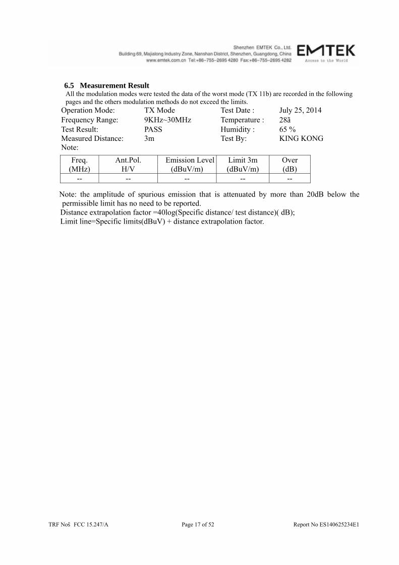
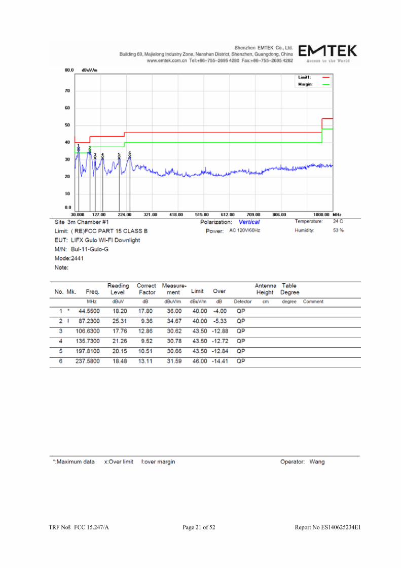
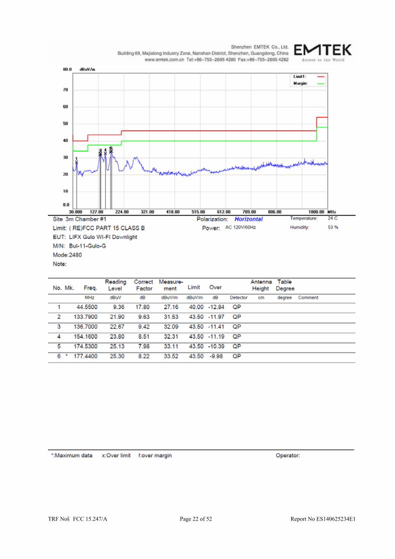
6.5 Measurement Result All the modulation modes were tested the data of the worst mode (TX 11b) are recorded in the following pages and the others modulation methods do not exceed the limits.
Operation Mode: TX Mode Test Date : July 25, 2014 Frequency Range: 9KHz~30MHz Temperature : 28 Test Result: PASS Humidity : 65 % Measured Distance: 3m Test By: KING KONG Note:
Freq. Ant.Pol. Emission Level Limit 3m Over
(MHz) H/V (dBuV/m) (dBuV/m) (dB) -- -- -- -- --
Note: the amplitude of spurious emission that is attenuated by more than 20dB below the
permissible limit has no need to be reported. Distance extrapolation factor =40log(Specific distance/ test distance)( dB); Limit line=Specific limits(dBuV) + distance extrapolation factor.

TRF No:FCC 15.247/A Page 18 of 52 Report No ES140625234E1

TRF No:FCC 15.247/A Page 19 of 52 Report No ES140625234E1

TRF No:FCC 15.247/A Page 20 of 52 Report No ES140625234E1
TRF No:FCC 15.247/A Page 21 of 52 Report No ES140625234E1
TRF No:FCC 15.247/A Page 22 of 52 Report No ES140625234E1

TRF No:FCC 15.247/A Page 23 of 52 Report No ES140625234E1

TRF No:FCC 15.247/A Page 24 of 52 Report No ES140625234E1
Operation Mode: 802.11b TX Channel 1 Test Date : July 25, 2014 Frequency Range: Above 1GHz Temperature : 28 Test Result: PASS Humidity : 65 % Measured Distance: 3m Test By: KING KONG
Freq.
(MHz) Ant.Pol. Emission Level(dBuV/m) Limit
3m(dBuV/m) Over(dB)
H/V PK AV PK AV PK AV 4823.75 V 54.59 41.19 74.00 54.00 -19.41 -12.81 7235.43 V 49.88 38.36 74.00 54.00 -24.12 -15.64 9748.12 V 50.28 37.06 74.00 54.00 -23.72 -16.94 4821.81 H 55.27 41.74 74.00 54.00 -18.73 -12.26 7235.51 H 49.68 38.28 74.00 54.00 -24.32 -15.72 9747.94 H 44.78 32.55 74.00 54.00 -29.22 -21.45
All emissions not reported were more than 20dB below the specified limit or in the noise floor.
Note: (1) All Readings are Peak Value and AV.
(2) Emission Level= Reading Level+Probe Factor +Cable Loss. (3) Data of measurement within this frequency range shown “ -- ” in the table above
means the reading of emissions are attenuated more than 20dB below the permissible limits or the field strength is too small to be measured.
Operation Mode: 802.11b TX Channel 6 Test Date : July 25, 2014 Frequency Range: Above 1GHz Temperature : 28 Test Result: PASS Humidity : 65 % Measured Distance: 3m Test By: KING KONG
Freq.
(MHz) Ant.Pol. Emission Level(dBuV/m) Limit
3m(dBuV/m) Over(dB)
H/V PK AV PK AV PK AV 4874.19 V 53.53 40.23 74.00 54.00 -20.47 -13.77 7310.59 V 49.47 37.75 74.00 54.00 -24.53 -16.25 9750.18 V 47.98 37.14 74.00 54.00 -26.02 -16.86 4873.62 H 56.94 42.92 74.00 54.00 -17.06 -11.08 7311.18 H 50.38 37.72 74.00 54.00 -23.62 -16.28 9748.33 H 43.22 31.21 74.00 54.00 -30.78 -22.79
All emissions not reported were more than 20dB below the specified limit or in the noise floor.
Note: (1) All Readings are Peak Value and AV.
(2) Emission Level= Reading Level+Probe Factor +Cable Loss. (3) Data of measurement within this frequency range shown “ -- ” in the table above
means the reading of emissions are attenuated more than 20dB below the permissible limits or the field strength is too small to be measured.

TRF No:FCC 15.247/A Page 25 of 52 Report No ES140625234E1
Operation Mode: 802.11b TX Channel 11 Test Date : July 25, 2014 Frequency Range: Above 1GHz Temperature : 28 Test Result: PASS Humidity : 65 % Measured Distance: 3m Test By: KING KONG
Freq. (MHz)
Ant.Pol. Emission Level(dBuV/m) Limit 3m(dBuV/m)
Over(dB)
H/V PK AV PK AV PK AV 4941.45 V 53.35 40.54 74.00 54.00 -20.65 -13.46 7460.37 V 50.55 38.48 74.00 54.00 -23.45 -15.52 9888.25 V 51.19 37.74 74.00 54.00 -22.81 -16.26 4941.57 H 55.43 41.67 74.00 54.00 -18.57 -12.33 7460.76 H 49.78 38.34 74.00 54.00 -24.22 -15.66 9887.91 H 44.92 32.55 74.00 54.00 -29.08 -21.45
No others harmonics emissions are higher than 20dB below the limits of 47 CFR Part 15.247.
Note: (1) All Readings are Peak Value and AV.
(2) Emission Level= Reading Level+Probe Factor +Cable Loss. (3) Data of measurement within this frequency range shown “ -- ” in the table above
means the reading of emissions are attenuated more than 20dB below the permissible limits or the field strength is too small to be measured.
TRF No:FCC 15.247/A Page 26 of 52 Report No ES140625234E1
7. 6dB Bandwidth Test
7.1 Measurement Procedure
1. The testing follows FCC KDB Publication No. 558074 DTS 001 Meas. Guidance v03r02
2. The RF output of EUT was connected to the spectrum analyzer by RF cable and attenuator. The path loss was compensated to the results for each measurement.
3. Set to the maximum power setting and enable the EUT transmit continuously 4. Make the measurement with the spectrum analyzer 's resolution bandwidth (RBW) = 100 kHz.Set the Video bandwidth (VBW) = 300 kHz. In order to make an accurate measurement The 6dB bandwidth must be greater than 500 kHz
5. Measure and record the results in the test report.
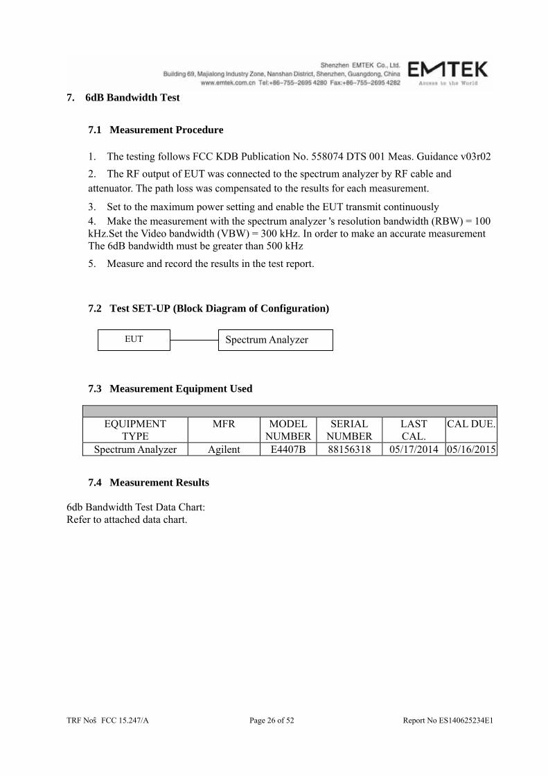
7.2 Test SET-UP (Block Diagram of Configuration)
7.3 Measurement Equipment Used
EQUIPMENT
TYPE MFR MODEL
NUMBERSERIAL
NUMBER LAST CAL.
CAL DUE.
Spectrum Analyzer Agilent E4407B 88156318 05/17/2014 05/16/2015
7.4 Measurement Results 6db Bandwidth Test Data Chart: Refer to attached data chart.
EUT Spectrum Analyzer
TRF No:FCC 15.247/A Page 27 of 52 Report No ES140625234E1
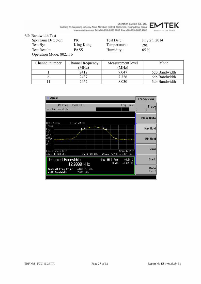
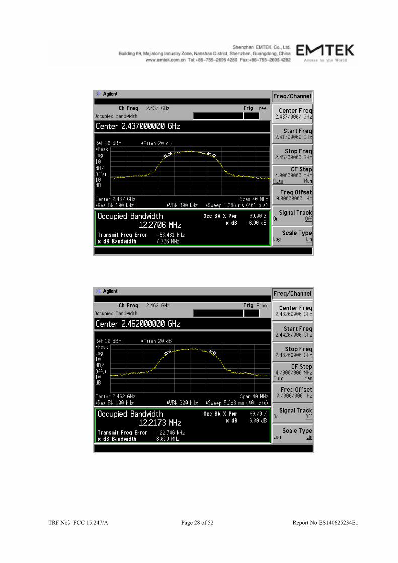
6db Bandwidth Test Spectrum Detector: PK Test Date : July 25, 2014 Test By: King Kong Temperature : 28 Test Result: PASS Humidity : 65 % Operation Mode: 802.11b
Channel number Channel frequency
(MHz) Measurement level
(MHz) Mode
1 2412 7.047 6db Bandwidth 6 2437 7.326 6db Bandwidth 11 2462 8.030 6db Bandwidth
TRF No:FCC 15.247/A Page 28 of 52 Report No ES140625234E1

TRF No:FCC 15.247/A Page 29 of 52 Report No ES140625234E1
Spectrum Detector: PK Test Date : July 25, 2014 Test By: King Kong Temperature : 28 Test Result: PASS Humidity : 65 % Operation Mode: 802.11 g
Channel number Channel frequency
(MHz) Measurement level
(MHz) Mode
1 2412 15.381 6db Bandwidth 6 2437 15.192 6db Bandwidth 11 2462 15.519 6db Bandwidth

TRF No:FCC 15.247/A Page 30 of 52 Report No ES140625234E1
TRF No:FCC 15.247/A Page 31 of 52 Report No ES140625234E1
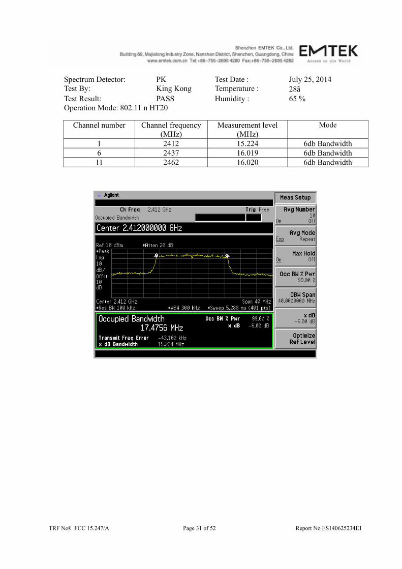
Spectrum Detector: PK Test Date : July 25, 2014 Test By: King Kong Temperature : 28 Test Result: PASS Humidity : 65 % Operation Mode: 802.11 n HT20
Channel number Channel frequency
(MHz) Measurement level
(MHz) Mode
1 2412 15.224 6db Bandwidth 6 2437 16.019 6db Bandwidth 11 2462 16.020 6db Bandwidth

TRF No:FCC 15.247/A Page 32 of 52 Report No ES140625234E1

TRF No:FCC 15.247/A Page 33 of 52 Report No ES140625234E1
8. Maximum Peak Output Power Test
8.1 Measurement Procedure
The maximum peak conducted output power can be measured using a broadband peak RF power meter. The power meter must have a video bandwidth that is greater than or equal to the DTS bandwidth and shall utilize a fast, average-responding diode type sensor.
a. The Transmitter output (antenna port) was connected to the power meter. b. Turn on the EUT and power meter and then record the peak power value. c. Repeat above procedures on all channels needed to be tested.
8.2 Test SET-UP (Block Diagram of Configuration) 10dB ATTENUATION
8.3 Measurement Equipment Used
EQUIPMENT TYPE
MODEL NUMBER
SERIAL NUMBER
LAST CAL. CAL DUE.
Power meter ML2495A 0824006 05/17/2014 05/16/2015
Power sensor MA2411B 0738172 05/17/2014 05/16/2015
8.4 Peak Power output limit
The maximum peak power shall be less 1Watt.
8.5 Measurement Results
Spectrum Detector: PK Test Date : July 25, 2014 Test By: King Kong Temperature : 28 Test Result: PASS Humidity : 65 % Operation Mode: 802.11b
Channel number
Channel Frequency(MHz)
Peak Power output(dBm)
Peak Power Limit(W)
Pass/Fail
1 2412 13.36 1W(30dBm) PASS 6 2437 13.60 1W(30dBm) PASS 11 2462 13.76 1W(30dBm) PASS
EUT Power meter

TRF No:FCC 15.247/A Page 34 of 52 Report No ES140625234E1
Spectrum Detector: PK Test Date : July 25, 2014 Test By: King Kong Temperature : 28 Test Result: PASS Humidity : 65 % Operation Mode: 802.11g
Channel number
Channel Frequency
(MHz)
Peak Power output(dBm)
Peak Power Limit(W)
Pass/Fail
1 2412.00 15.69 1W(30dBm) PASS 6 2437.00 15.88 1W(30dBm) PASS 11 2462.00 16.12 1W(30dBm) PASS
Spectrum Detector: PK Test Date : July 25, 2014 Test By: King Kong Temperature : 28 Test Result: PASS Humidity : 65 % Operation Mode: 802.11n H20
Channel number
Channel Frequency(MHz)
Peak Power output(dBm)
Peak Power Limit(W)
Pass/Fail
1 2412.00 15.73 1W(30dBm) PASS 6 2437.00 15.80 1W(30dBm) PASS 11 2462.00 15.94 1W(30dBm) PASS
Spectrum Detector: PK Test Date : July 25, 2014 Test By: King Kong Temperature : 28 Test Result: PASS Humidity : 65 % Operation Mode: Wifi+Zigbee
Max Wifi
Peak Power output(dBm)
Max Zigbee Peak Power output(dBm)
Combined Peak Power
output(dBm)
Peak Power Limit(W)
Pass/Fail
16.12 -3.42 16.17 1W(30dBm) PASS

TRF No:FCC 15.247/A Page 35 of 52 Report No ES140625234E1
9. Band Edge Test
9.1 Measurement Procedure
1. The EUT was Operating in hopping mode or could be controlled its channel. Printed out test result from the spectrum by hard copy function.
2. The EUT was placed on a turn table which is 0.8m above ground plane. 3. Maximum procedure was performed on the six highest emissions to ensure EUT
compliance. 4. And also, each emission was to be maximized by changing the polarization of receiving
antenna both horizontal and vertical. 5. Repeat above procedures until all frequency measured were complete.
When spectrum scanned above 1GHz setting resolution bandwidth 1MHz, video bandwidth 3MHz. EMI Test Receiver Setting Attenuation Auto RB 1MHz VB 3MHz Detector Peak Trace Max hold
When spectrum scanned above 1GHz setting resolution bandwidth 1MHz, video bandwidth 10Hz. EMI Test Receiver Setting Attenuation Auto RB 1MHz VB 10Hz Detector Peak Trace Max hold
9.2 Test SET-UP (Block Diagram of Configuration) As 6.2 Test set up (B) and (C)
9.3 Measurement Equipment Used Same as 6.3 Radiated Emission Measurement.
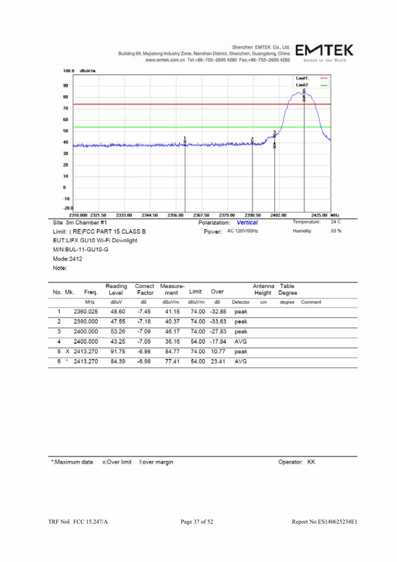
9.4 Measurement Results

TRF No:FCC 15.247/A Page 36 of 52 Report No ES140625234E1
TRF No:FCC 15.247/A Page 37 of 52 Report No ES140625234E1
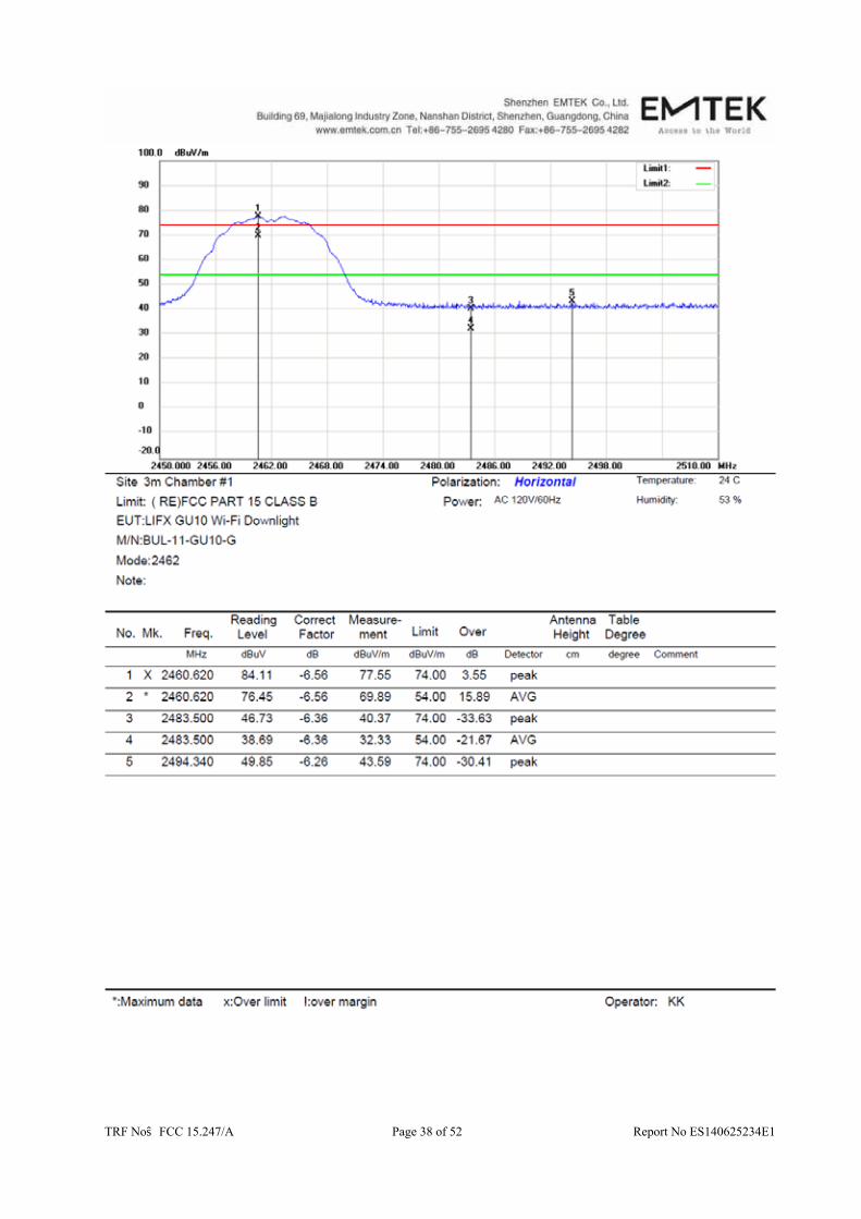
TRF No:FCC 15.247/A Page 38 of 52 Report No ES140625234E1
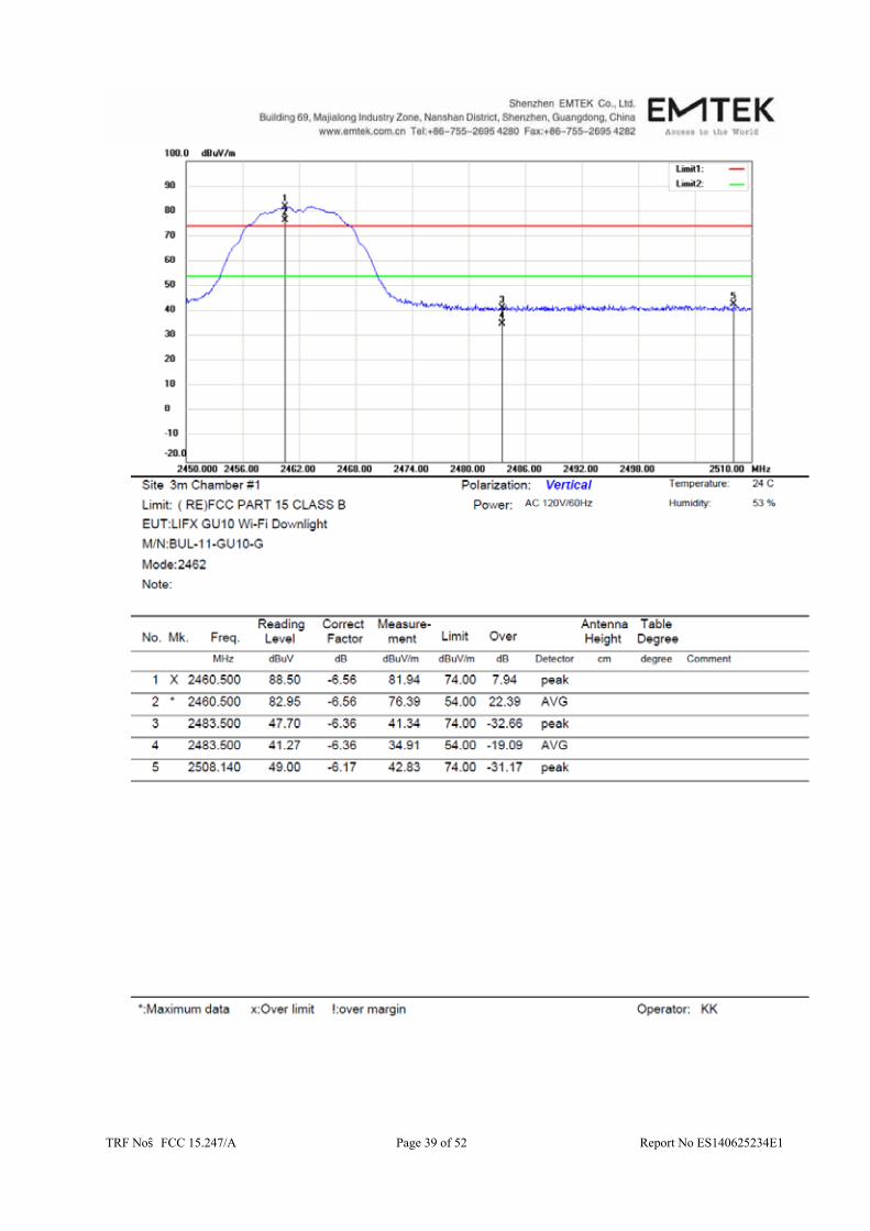
TRF No:FCC 15.247/A Page 39 of 52 Report No ES140625234E1
TRF No:FCC 15.247/A Page 40 of 52 Report No ES140625234E1
10. Power Density
10.1 Test Equipment
EQUIPMENT
TYPE MFR MODEL
NUMBERSERIAL
NUMBER LAST CAL.
CAL DUE.
Spectrum Analyzer Agilent E4407B 88156318 05/17/2014 05/16/2015
10.2 Measuring Instruments and Setting
The following table is the setting of spectrum analyzer. Spectrum analyzer Setting Attenuation Auto Span Frequency Set the span to 1.5 times the DTS bandwidth. RB 3kHz ≥RBW ≤100KHz VB 3 x RBW Detector Peak Trace Max hold Sweep Time Automatic
10.3 Test Procedures
a. The transmitter output (antenna port) was connected to the spectrum analyzer. b. Set analyzer center frequency to DTS channel center frequency. c. Set the analyzer span to a minimum of 1.5 times the DTS bandwidth. d. Set the RBW ≥ 3 kHz. Set the VBW ≥ 3 x RBW. e. Detector = peak. f. Sweep time = auto couple. g. Trace mode = max hold. h. Allow trace to fully stabilize. i. Use the peak marker function to determine the maximum amplitude level within the RBW.
10.4 Block Diagram of Test Setup
10.5 Limit
The transmitted power density averaged over any 1 second interval shall not be greater +8dBm in any 3 kHz bandwidth.
EUT Spectrum Analyzer

TRF No:FCC 15.247/A Page 41 of 52 Report No ES140625234E1
10.6 Test Result
Spectrum Detector: PK Test Date : July 25, 2014 Test By: King Kong Temperature : 28 Test Result: PASS Humidity : 65 % Operation Mode: 802.11 b
Channel Measurement Level
(dBm) Required Limit
(dBm) Result
1 -12.94 <8dBm PASS 6 -12.76 <8dBm PASS 11 -12.82 <8dBm PASS

TRF No:FCC 15.247/A Page 42 of 52 Report No ES140625234E1
TRF No:FCC 15.247/A Page 43 of 52 Report No ES140625234E1
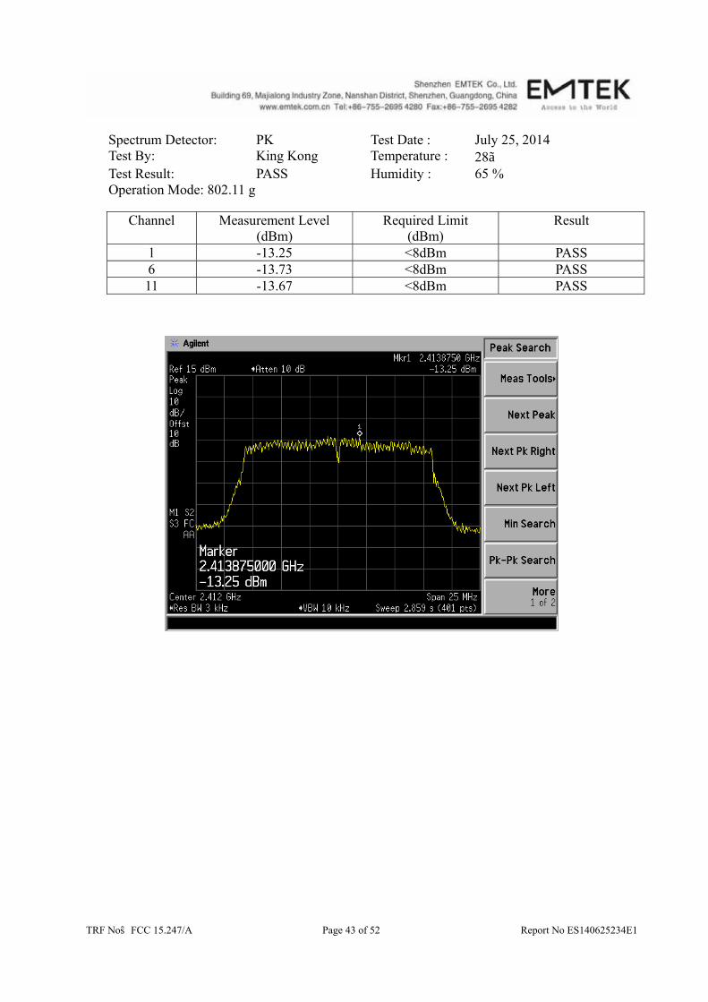
Spectrum Detector: PK Test Date : July 25, 2014 Test By: King Kong Temperature : 28 Test Result: PASS Humidity : 65 % Operation Mode: 802.11 g
Channel Measurement Level
(dBm) Required Limit
(dBm) Result
l -13.25 <8dBm PASS 6 -13.73 <8dBm PASS 11 -13.67 <8dBm PASS

TRF No:FCC 15.247/A Page 44 of 52 Report No ES140625234E1
TRF No:FCC 15.247/A Page 45 of 52 Report No ES140625234E1
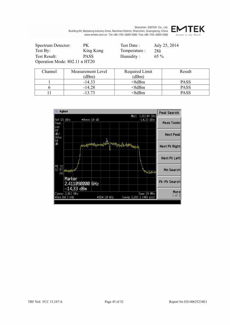
Spectrum Detector: PK Test Date : July 25, 2014 Test By: King Kong Temperature : 28 Test Result: PASS Humidity : 65 % Operation Mode: 802.11 n HT20
Channel Measurement Level
(dBm) Required Limit
(dBm) Result
l -14.33 <8dBm PASS 6 -14.28 <8dBm PASS 11 -13.73 <8dBm PASS

TRF No:FCC 15.247/A Page 46 of 52 Report No ES140625234E1
TRF No:FCC 15.247/A Page 47 of 52 Report No ES140625234E1
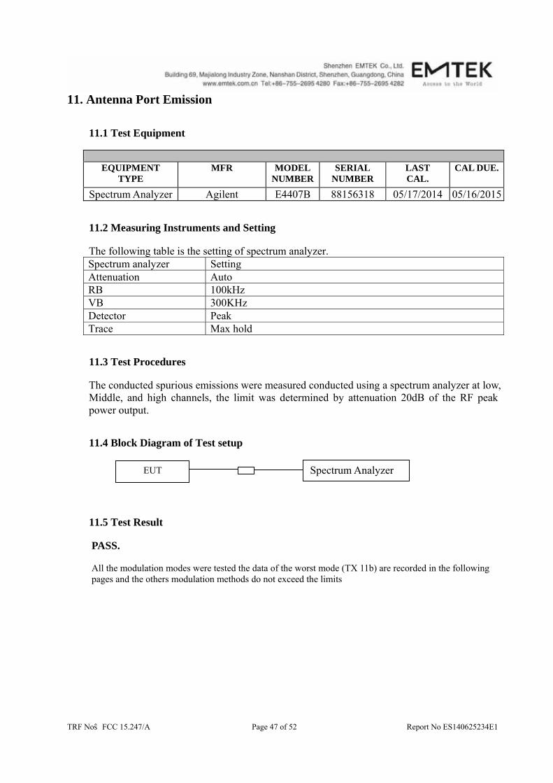
11. Antenna Port Emission
11.1 Test Equipment
EQUIPMENT
TYPE MFR MODEL
NUMBERSERIAL
NUMBER LAST CAL.
CAL DUE.
Spectrum Analyzer Agilent E4407B 88156318 05/17/2014 05/16/2015
11.2 Measuring Instruments and Setting
The following table is the setting of spectrum analyzer. Spectrum analyzer Setting Attenuation Auto RB 100kHz VB 300KHz Detector Peak Trace Max hold
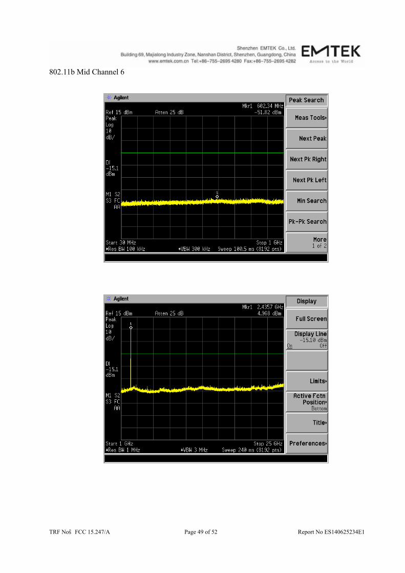
11.3 Test Procedures The conducted spurious emissions were measured conducted using a spectrum analyzer at low,
Middle, and high channels, the limit was determined by attenuation 20dB of the RF peak power output.
11.4 Block Diagram of Test setup
11.5 Test Result
PASS. All the modulation modes were tested the data of the worst mode (TX 11b) are recorded in the following pages and the others modulation methods do not exceed the limits
EUT Spectrum Analyzer

TRF No:FCC 15.247/A Page 48 of 52 Report No ES140625234E1
802.11b Low Channel 1
TRF No:FCC 15.247/A Page 49 of 52 Report No ES140625234E1
802.11b Mid Channel 6

TRF No:FCC 15.247/A Page 50 of 52 Report No ES140625234E1
802.11b High Channel 11

TRF No:FCC 15.247/A Page 51 of 52 Report No ES140625234E1
12. Antenna Application
12.1 Antenna Requirement
Standard Requirement
FCC CRF Part 15.203
An intentional radiator shall be designed to ensure that no antenna other than that furnished by the responsible party shall be used with the device. The use of a permanently attached antenna or of an antenna that uses a unique coupling to the intentional radiator shall be considered sufficient to comply with the provisions of this section. The manufacturer may design the unit so that a broken antenna can be replaced by the user, but the use of a standard antenna jack or electrical connector is prohibited. This requirement does not apply to carrier current devices or to devices operated under the provisions of §15.211, §15.213, §15.217, §15.219, or §15.221. Further, this requirement does not apply to intentional radiators that must be professionally installed, such as perimeter protection systems and some field disturbance sensors, or to other intentional radiators which, in accordance with §15.31(d), must be measured at the installation site. However, the installer shall be responsible for ensuring that the proper antenna is employed so that the limits in this part are not exceeded.
For intentional device, according to FCC 47 CFR Section 15.203, an intentional radiator shall be designed to ensure that no antenna other than that furnished by the responsible party shall be used with the device. And according to FCC 47 CFR Section 15.247 (b), if transmitting antennas of directional gain greater than 6dBi are used, the power shall be reduced by the amount in dB that the directional gain of the antenna exceeds 6dBi. The EUT has 2 antennas: a Chip antenna for 2.4G WIFI, the gain is 1.5 dBi;
a Chip antenna for Zigbee, the gain is 1.1 dBi; Note:Antenna use a permanently attached antenna which is not replaceable.
which in accordance to section 15.203, please refer to the internal photos.
12.2 Result
PASS.

TRF No:FCC 15.247/A Page 52 of 52 Report No ES140625234E1
13. Uncertainty Measurement Uncertainty for a level of Confidence of 95%
Parameter Uncertainty Radio Frequency ±1x10^-5
Maximum Peak Output Power Test ±1.0dB Conducted Emissions Test ±2.0dB
Radiated Emission Test ±2.0dB Power Density ±2.0dB
Occupied Bandwidth Test ±1.0dB Band Edge Test ±3dB
All emission, radiated ±3dB Antenna Port Emission ±3dB
Temperature ±0.5 Humidity ±3%